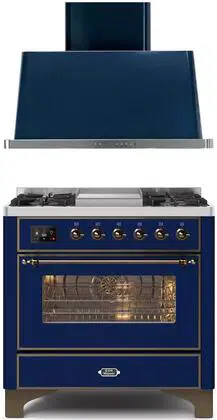

HOODS
NOBLESSE
UANB30 - UANB36 - UANB40 - UANB48 - UANB60 -
UANB72
USER – Use and Maintenance
INSTALLER - Installation manual
cod. EI33960360000
43/2022
EN


INDEX
USER (4-12)
4
6
8
10
12
12
13
15
24
26
USEFUL INFORMATION
IMPORTANT SAFETY WARNING
INSTRUCTIONS FOR USE
CLEANING AND MAINTENANCE
PERIODS OF INACTIVITY
ORDINARY MAINTENANCE - replacement of the spotlight
IMPORTANT SAFETY WARNINGS
INSTALLATION
IMPORTANT SAFETY WARNINGS
INSTALLATION
INSTALLER (13-28)

4
USEFUL INFORMATION
thank you for choosing our equipment!
Our hoods are capable of efciently extracting fumes
and steam generated by cooking food from domestic
environments.
This booklet contains all the necessary information for
using and maintaining the equipment.
It will guide you through starting using the hood quickly
and without difculty. We therefore recommend that you
read it carefully before use, and that you store it carefully
for futurereference.
We remain at your full disposal for any further information
that you may require, or if you have any
problems in understanding any contents of this booklet.
ILVE S.p.a.
Via Antoniana, 100
35011 Campodarsego (PD) Italy
tel. +39 049 9200990 - fax +39 049 9201010
SEND MAIL: [email protected]
DEAR CUSTOMER
5
USER
LEGEND
Read this manual carefully before installing or using the
equipment.
The manual contains some warning or danger symbols:
Danger! Situation of immediate danger or dangerous si-
tuation that might cause injuries or death.
Electrical shock hazard!
Earthing symbol
Equipotential symbol
Read the instruction manual
Useful advice and information
Reference to another chapter
The Manufacturer reserves the right to make improving
modications to the equipment or accessories at any
time. Partial reproduction without th.
Manufacturer’s authorization is forbidden. The measure-
ments given are indicative and not binding.
ICON
ATTENTION:
6
IMPORTANT SAFETY WARNINGS
- This booklet contains important information about the
use and maintenance of your equipment and is an in-
tegral and essential part of the product. Please read this
booklet carefully before proceeding with any operations,
in order to protect your safety and avoid damaging the
product.
- Store the booklet safely for further consultation, and give
it to the new owner if you sell the equipment, since the
information therein is addressed to the purchaser and all
the people that, one way or another, use and maintain
the product.
- ILVE S.p.a. (hereinafter referred to as “the Manufacturer”)
denies any and all liability due to the
failure to comply with the instructions below, including any
damage caused from misuse and unauthorized
changes in the product, as well as the use of non genu
ine spare parts supplied by ILVE S.p.a.
-The equipment is only intended for the extraction of co-
oking fumes from a domestic, non professional, environ-
ment. Any other use is considered improper use, can cau-
se damage to people, property and animals, and shall
relieve the
Manufacturer from all responsibility.
- If the equipment does not work, or functional or structural
alterations are noted, disconnect it from the power mains
and contact a service centre authorised by the
manufacturer. Do not attempt any repairs yourself. Always
request that original spare parts
are used.
- Do not touch the hood with wet or dirty hands, or while
barefoot.
- When not in use, check that all electric components
7
USER
IMPORTANT SAFETY WARNINGS
(lights, suction fan) are switched off.
- Check fryers during use: overheated oil may catch re.
- Do not ignite open ames or cook ambé foods under
the hood.
- Never use the hood without the anti-grease lters sup-
plied: this could lead to an accumulation of fat and dirt,
which could severely harm the operational parts of the
product, primarily the blower.
Guidelines for the routine maintenance of the range hood
- disconnecting the electric power supply;
- always wear appropriate personal protective equipment
(e.g. gloves, safety footwear, etc.);
- after the surfaces of the hood have COOLED DOWN;
- always wear appropriate personal protective equipment
(i.e., gloves, safety footwear, etc.).
- Failure to follow the instructions or the use of unsuitable
cleaning devices may pose a risk of re and/or damage
to the hood or the surrounding objects, so the
Manufacturer couldn’t be held responsible.
- egular daily cleaning and maintenance activities should
not be performed by children.
- The maximum weight of any objects placed on top of
the hood or attached to the same should not exceed 2
kg (4,4 lb).
- Do not pull, push or hang on the equipment, neither use
the hood as a support for heavy objects or cabinet and
other appliances.Interrompere l’alimentazione elettrica.
8
cappa ad
evacuazione
esterna
vapori
fumi e
fumi e
vapori
cappa
a ricircolo
interno
metallici
metallici
carbone
attivo
external
evacuation
hood
fumes and
steam
metal lters
Fig. 1.
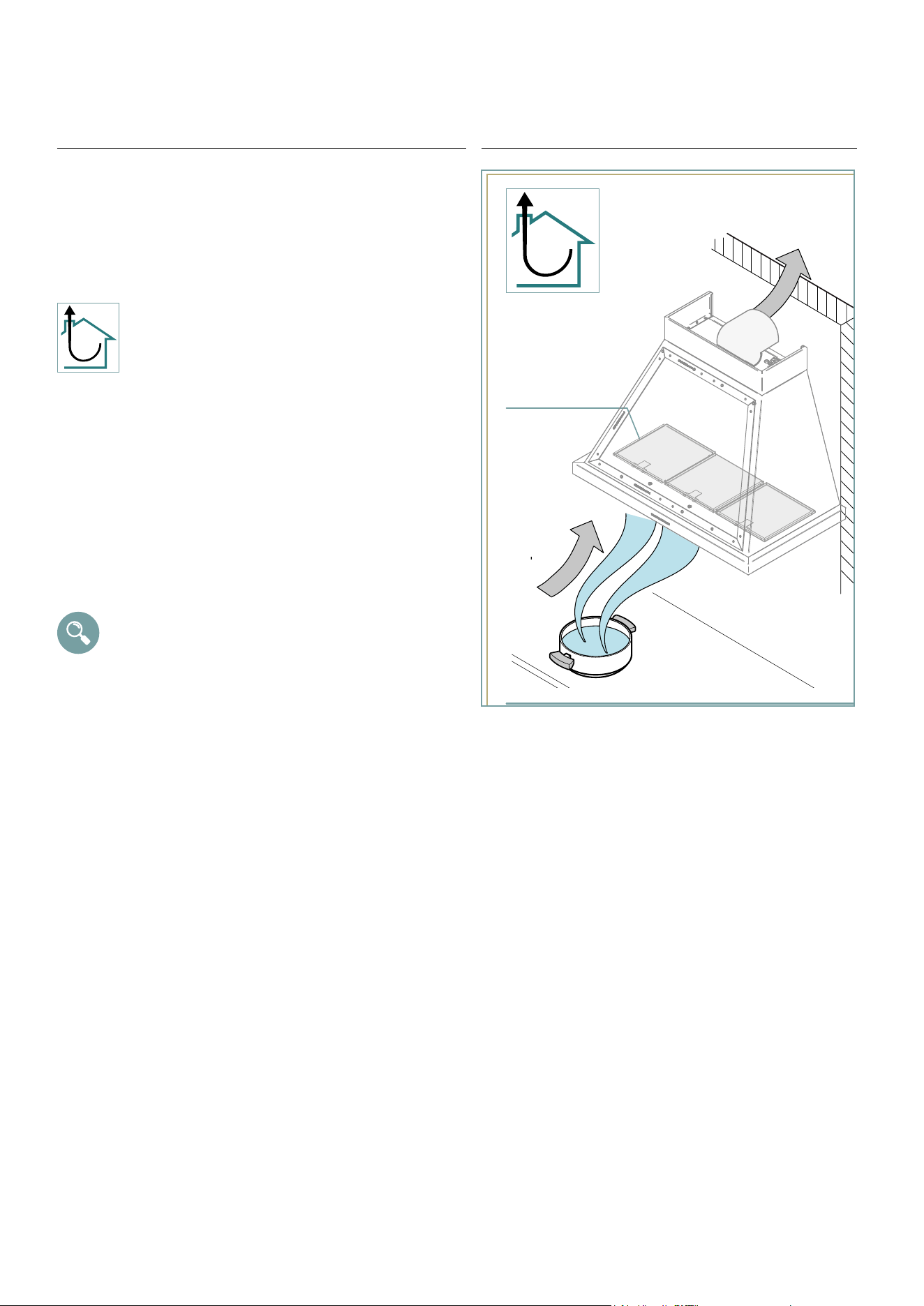
INSTRUCTIONS FOR USE
Product’s operation
The hood extract fumes and steam generated during
cooking from the environment, channelling them through
metal lters that must be regularly removed and washed.
And then, depending on the type of installation, fumes
and steam:
are driven outside from the building through a
drain pipe: this model does not require the use of
carbon lters (ducting or external drain cooker
hood - Fig. 1.);
Operating instructions
The hood must be switched on at least a couple of
minutes
before starting to cook, to promote the suction of fumes
and steam.
After nishing cooking, leave the hood in operation for an
extra few minutes: in this case, it may be appropriate to
activate the “Timer” function, which automatically switches
the hood off after 10 minutes.
The page that follows shows how to use the control
panel.
What speed should I use?
The unit operates at three different speeds:
speed 1: puries the air whilst limiting electricity consump-
tion;
speed 2: normal conditions of use (e.g. steam suction)
speed 3: for the elimination of particularly intense fumes
and smells (e.g: when frying or grilling).
When should the lters be washed or replaced?
metal lters: these must be removed and washed at least
once a month.
9
USER
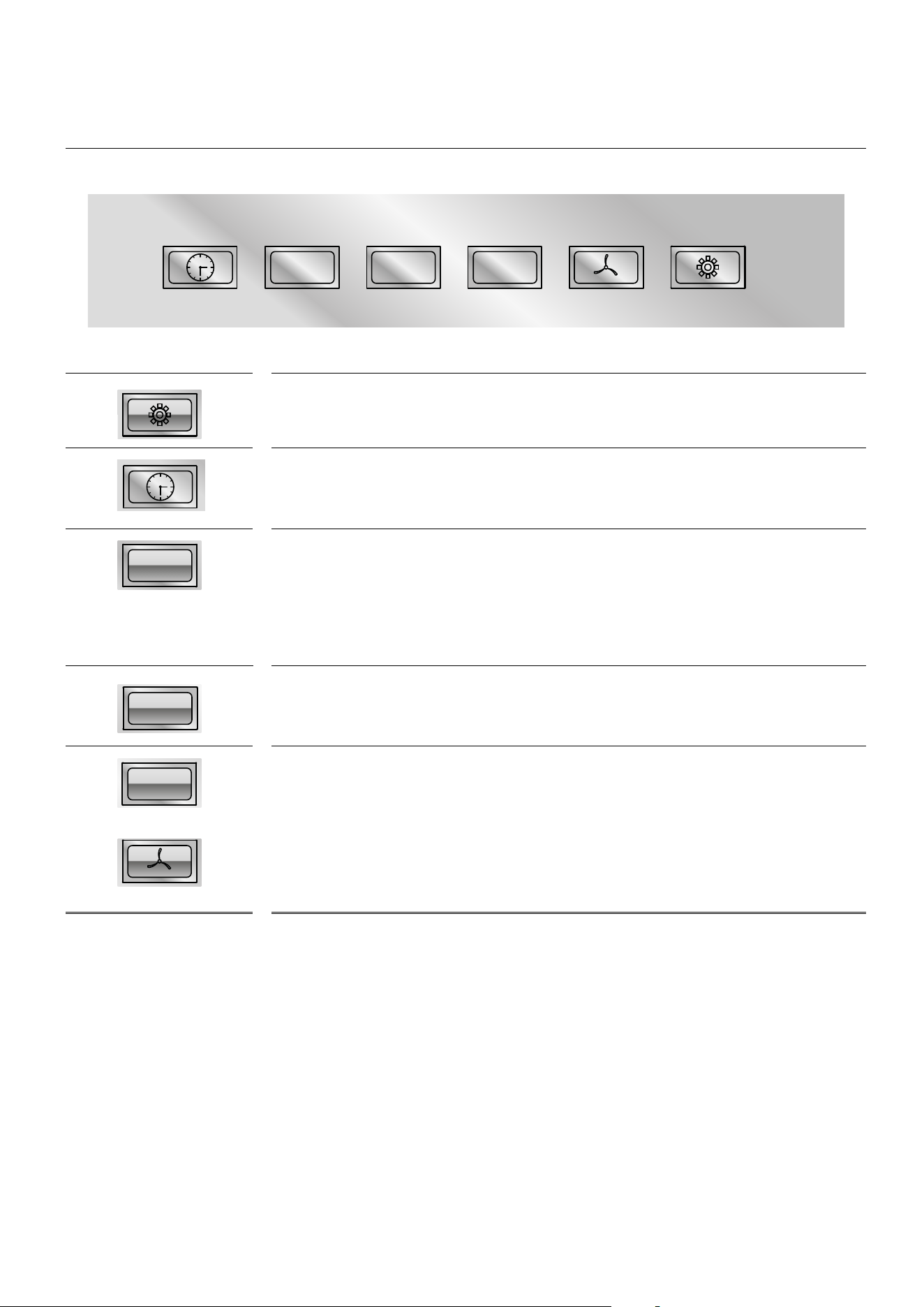
INSTRUCTIONS FOR USE
Fig. 2.
LIGHT SWITCH
lts function is to switch the light on and off.
TIMER BUTTON:
(Clock symbol). lts function is to enter the automatic switch off.
BUTTON 1: ON/ OFF (turns on and off the engine). lt adjusts the motor to the rst speed.
RECYCLING AIR 24 HOURS: By pushing button “0/1” for 7 seconds, the recycling air pro-
gram will be switched on or off (for 24 hours alternating functioning: switched off for 20
minutes and on for 5 minutes in rst speed).
BUTTON 2:
lt adjusts the motor at the second speed.
BUTTON 3:
lt adjusts the motor at the third speed.
BUTTON INTENSIVE FAN:
lt adjusts the motor at full speed for 5 minutes and after that, automaticalty returns to
the third speed.
TIMER FUNCTION:
By pressing the “TIMER” push button while the hood is working, the clock symbol will start
ashing.
Once the timer is set, the hood will continue working for about 10 minutes and then it
will automatically switch off. The timer can be switched off at any moment by pressing
its push button. In this case, the hood will continue working as previously set.
0/1
2 3
WORKING PAN EL
0/1
2 3
0/1
2 3
0/1
2
3
0/1
2
3
0/1
2 3
0/1
2 3
10
Fig. 4.
Fig. 2.
CLEANING AND MAINTENANCE
All ordinary maintenance operations must be
carried out:
• after disconnecting the electric power supply;
• always wearing appropriate personal protective equipment (e.g.: gloves, etc...).
Failure to follow the instructions, or use of unsuitable products, may pose a risk of re
and/or damage to the equipment or other objects, for which the Manufacturer
cannot be held responsible.
• When cleaning any of the components or accessories, NEVER use:
• abrasive or powder detergents;
• aggressive or corrosive detergents (e.g. hydrochloric/muriatic or sulphuric acid).
• abrasive or sharp tools (e.g. abrasive sponges, scrapers, steel brushes, etc.);
• water sprays
The INSIDE and the OUTSIDE of the hood should be cleaned solely by using a damp
cloth with little neutral soap. It is also possible to use a steel specic cleanser, paying
attention to the instructions written on the canister or bottle.
To conclude the cleaning operation, rinse using a clean wet sponge or cloth and then
use a rag to dry the surface (in case of satin steel, please rub according to the nish
pattern).
Please follow the instructions stated above for metal surfaces.
STAINLESS STEEL AND OTHER
METAL SURFACES
CONTROL PANEL
anti-grease metal lter
Fig.4
11
USER
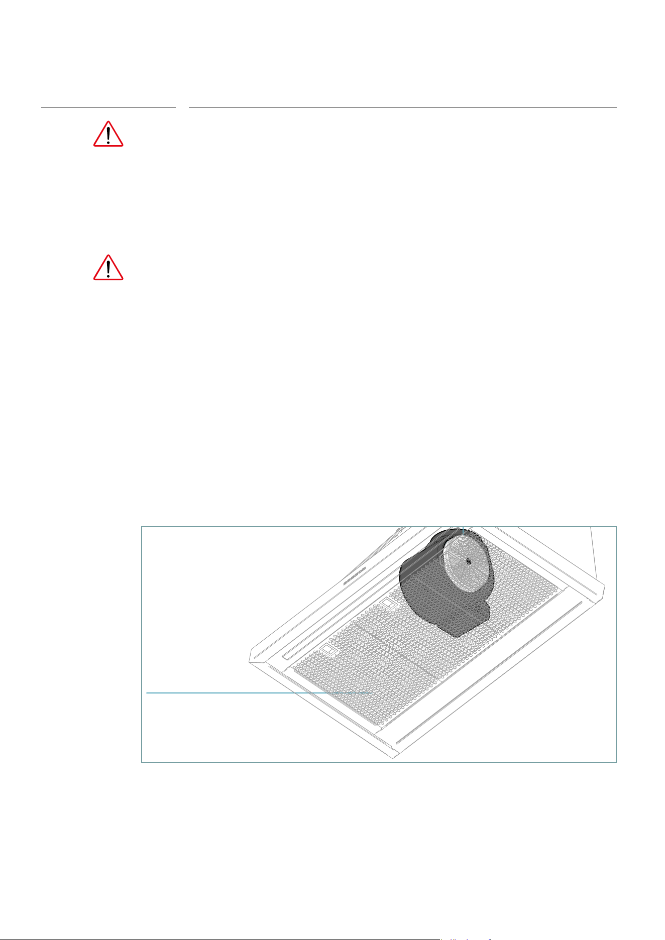
CLEANING AND MAINTENANCE
GREASE METAL FILTERS
These lters are usually made in aluminium or stainless
steel, and their main purpose is to block the particles of oil
and fat suspended in the cooking fumes.
An excessive accumulation of grease inside the lters
could cause unpleasant smells and decrease the suction
power of the hood. Please note that accumulated fat is
highly ammable: any re could lead to severe damage to
both users and the product.
For these reasons, the anti-grease lters should be washed
at least once a month, immersing them into hot water and
dish soap for at least one hour.
Rinse with plenty of water and wait for the lters to be fully
dry before putting them back in place.
Please note that the maximum temperature is 70°C/158°F:
higher temperature can cause darkening in the metal
(please note that this DOES NOT impair the operation of
the lter).
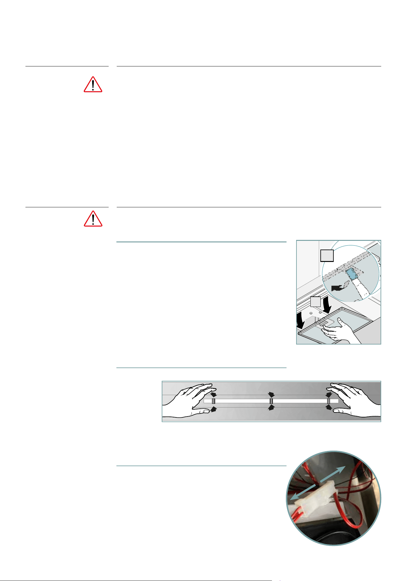
Fig.5
2
1
Fig. 5.
STEP 2
STEP 3
OK!
1
1
12
PERIODS OF INACTIVITY
When not using the equipment for extended periods of times:
• disconnect the equipment from the power supply.
• if possible, use a soft cloth to apply a thin layer of Vaseline oil to all stainless steel
surfaces.
At rst use:
• accurately clean the equipment;
• reconnect the power supply
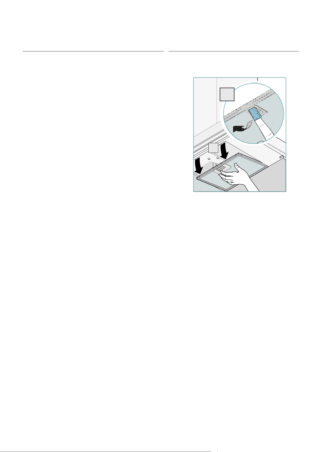
ALWAYS MAKE SURE THAT THE APPLIANCE IS DISCONNECTED FROM THE NETWORK
1-2 Remove the metal lters
3. Press the tabs and push the LED bar outwards
4. Disconnect and replace the led bar
PROCEDIMENTO
DA SEGUIRE
ORDINARY MAINTENANCE - LED bar replacement
2
1
Fig. 5.
STEP 2
STEP 3
OK!
1
1
13
INSTALLER
WARNING: This appliance must be grounded. In the event
of an electrical short circuit, grounding reduces the risk of
electric shock by providing an escape wire for the electric
current. This appliance is equipped with a cord having a
grounding wire with a grounding plug.
WARNING: Improper grounding can result in a risk of
electric shock.
Consult a qualied electrician if the grounding instructions
are not completely understood, or if doubt exists as to
whether the appliance is properly grounded.
Do not use an extension cord. If the power supply cord is
too short, have a qualied electrician install an outlet near
the appliance.
WARNING: “TO REDUCE THE RISK OF FIRE, USE ONLY METAL
DUCTWORK”.
WARNING: TO PROVIDE PROTECTION AGAINST ELECTRIC
SHOCK, CONNECT TO PROPERLY GROUNDED OUTLETS ONLY
WARNING: there shall be adequate ventilation of the
room when the range hood is used at the same time as
appliances burning gas or other fuels (not applicable to
appliances that only discharge the air back into the room);
there is a re risk if cleaning is not carried out in
accordance with the instructions;
CAUTION: Accessible parts may become hot when used
with cooking appliances.”
WARNING: lImproper bonding to ground can result in a risk
of electric shock.
IMPORTANT SAFETY WARNINGS

14
If the SUPPLY CORD is damaged, it must be replaced by
the manufacturer, its ervice agent or similarly qualied
persons in order to avoid a hazard.”
Before installing the equipment, carefully read the safety
instructions page 6 and the indications provided from
page 13.
IMPORTANT SAFETY WARNINGS
15
INSTALLER
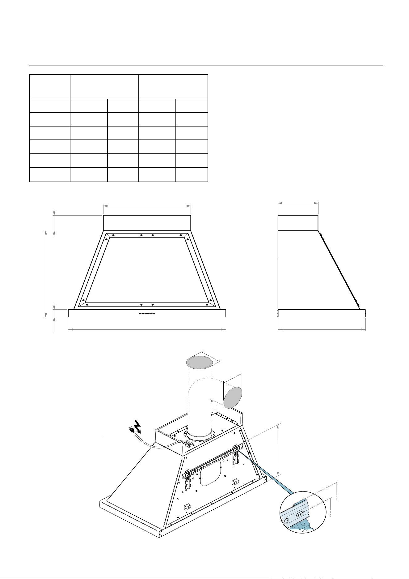
INSTALLATION
900 mm - 1000 mm - 1200 mm - 1500 mm
50 mm | 2 ”
19
3/4
” - 23
2/4
” - 31
2/4
”
100 mm | 4 ”
560 mm | 22 ”
230 mm | 9 ”
500 mm | 19
3/4
”
390 mm | 15
1/4
”
410 mm
| 16
1/4
”
ø150 mm |ø 6”
ø 200 mm | 7
3/4”
ø150 mm |ø 6”
ø 200 mm | 7
3/4”
120 V
60 Hz
35
1/2
” - 39
1/4
“ - 47
1/4
” - 59”
500 mm - 600 mm - 800 mm
MOD. Ø EXIT HOLE
(mm) (“)
SUCTION
(m
3/
h) (cfm)
UANB30
150 5
7/8”
1000 590
UANB36
150 5
7/8”
1000 590
UANB40
150 5
7/8”
1000 590
UANB48
150 5
7/8”
1000 590
UANB60
150 5
7/8”
1000 590
UANB72
150 5
7/8”
1000 590
16
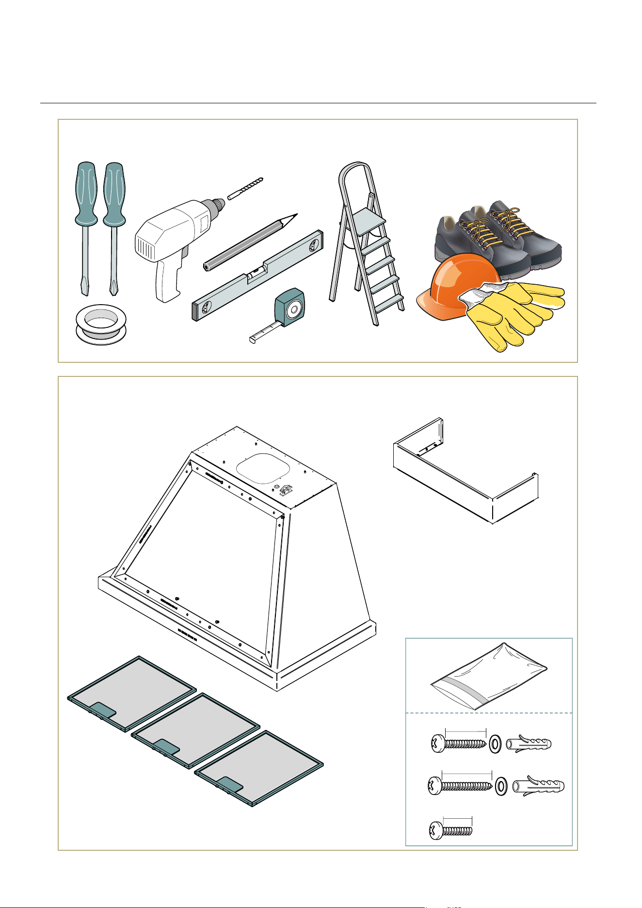
ø8 mm
UTENSILI NECESSARI
CONTENUTO IMBALLO
ø 0
5/16”
40 mm
45 mm
x2
x4
9 mm
x 7
INSTALLATION
NECESSARY TOOLS
PACKAGE CONTENT
x2
40 mm | 1
37/64”
45 mm | 1
49/64”
x2
x4
ø8 mm
UTENSILI NECESSARI
CONTENUTO IMBALLO
ø 0
5/16”
10 mm | 0
25 ⁄ 64”
x2
17
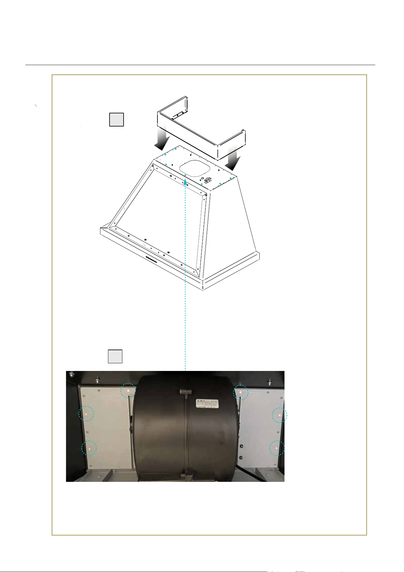
INSTALLER
cornice porta ltri (metallici)
motore con foro
d’uscita superiore
motore con foro d’uscita a parete
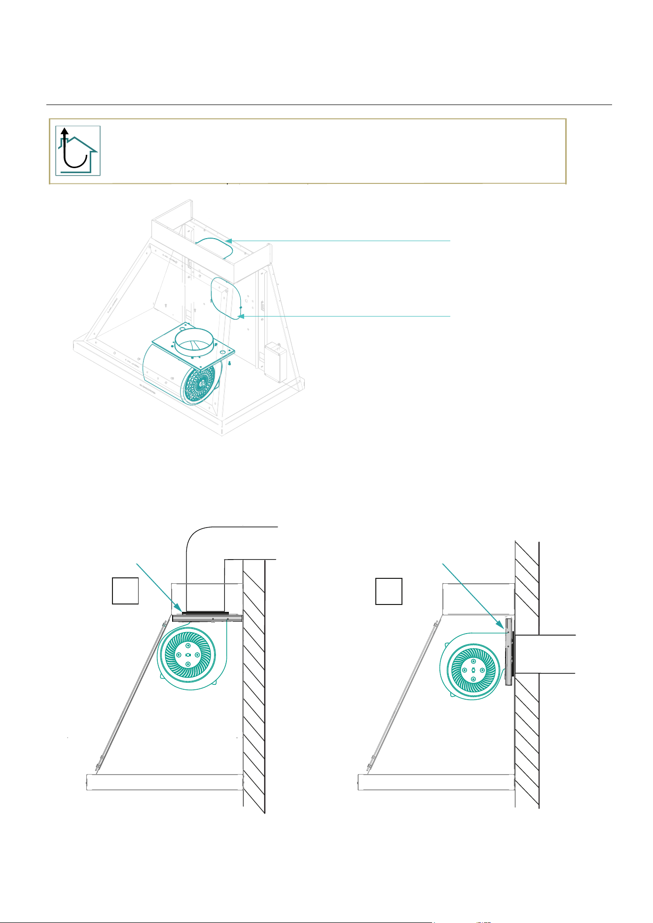
Cappa ad evaquazione esterna
cornice porta ltri (metallici)
STEP 1 - A
A B
STEP 1 - B
Rivolgere il foro d’uscita nella parte superiore
della cappa e ssare li motore (viti non fornite)
Rivolgere il foro d’uscita verso la parete
e ssare li motore (viti non fornite)
LATO SUPERIORE
LATO SUPERIORE
LATO PARETE LATO PARETE
A
B
ruotare il motore e
fissare nella parte
superiore
ruotare il motore e
fissare nella parte
posteriore della cappa
A - wall outlet hole
B - upper exit hole
INSTALLATION
rotate the motor and x
in the upper part of the
hood
faire tourner le moteur
et le xer dans la partie
arrière du capot
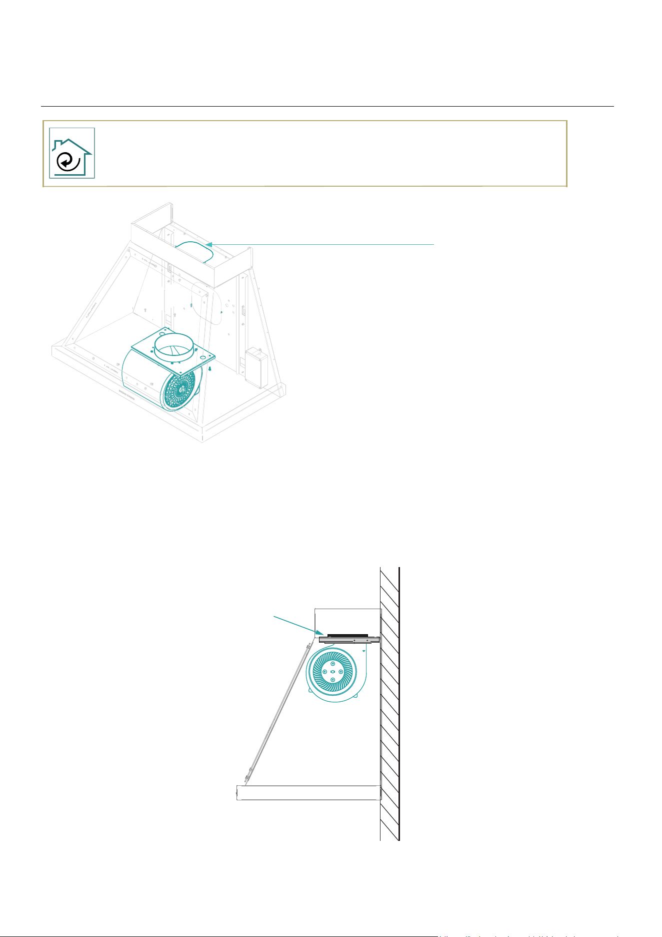
Hood with external evacuation
18
ruotare il motore e
fissare nella parte
superiore della cappa
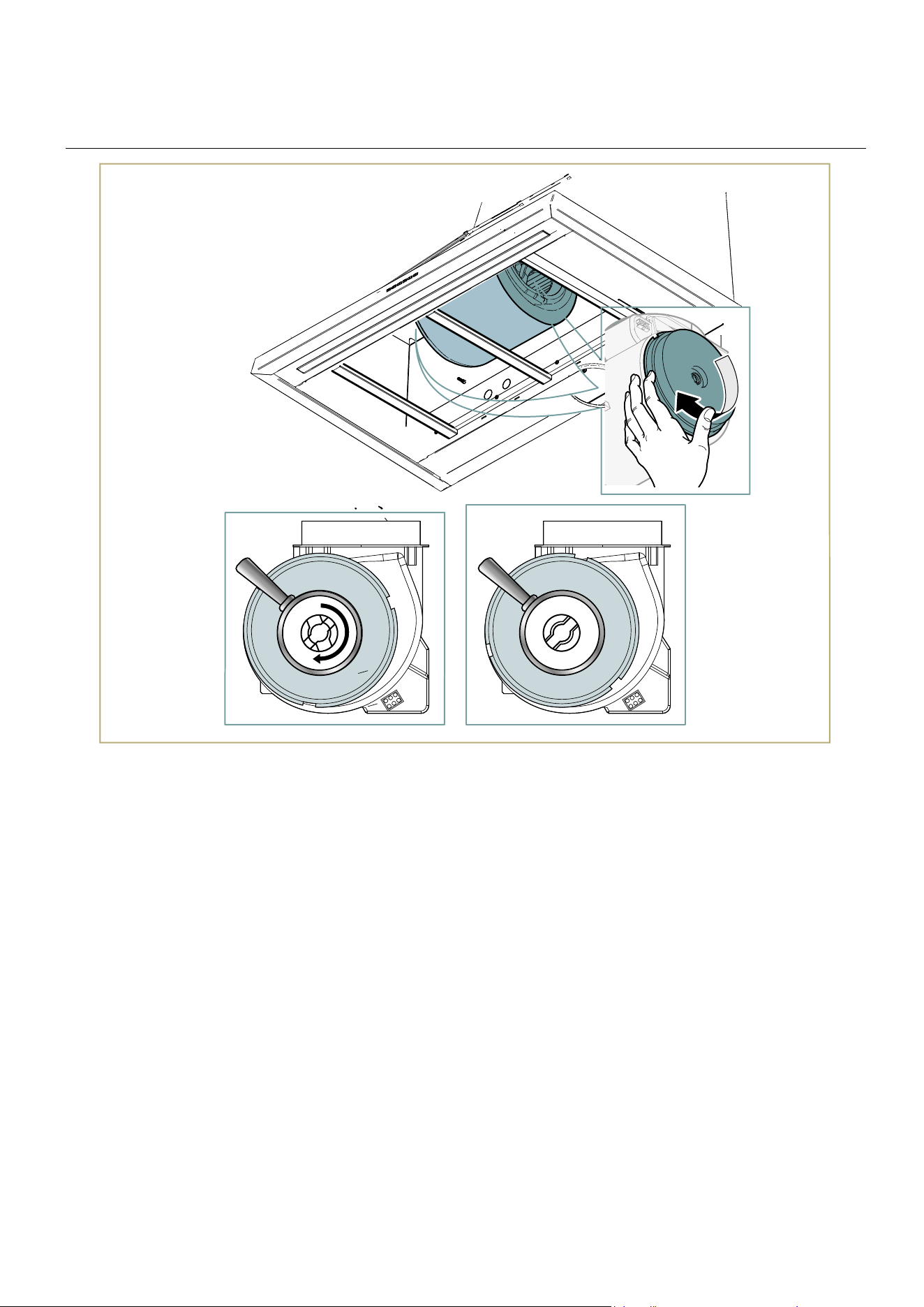
cornici porta ltri (metallici)
motore con ltri
ai carboni
Cappa a ricircolo interno
STEP 1
A
Fissare il motore con il foro d’uscita verso l’alto
(viti non fornite)
upper exit hole
INSTALLATION
rotate the motor and x
in the upper part of the
hood
Internal recirculation hood

19
INSTALLER
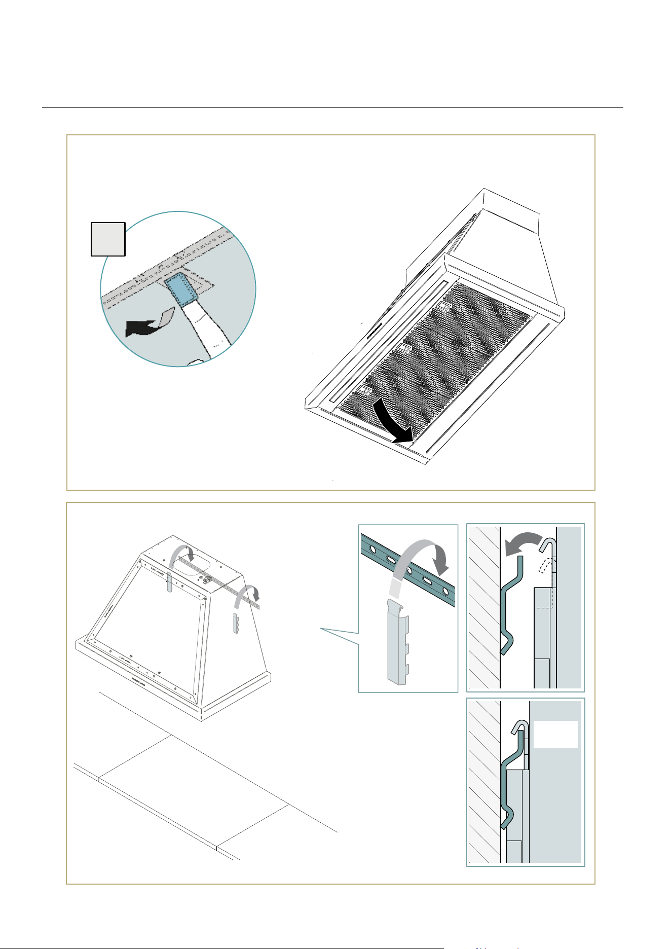
STEP 1
x2
2
3
=
=
1
1060 MM
1060 mm |
45 mm | 1
49/64”
ø8 mm
ø 0
5/16”
The fastening kit (screws and plugs) supplied with
the hood can only be used on masonry wall.
For installation on other types of walls consider
alternative fastening systems, taking into a
count the strength of the wall itself and the wei-
ght of the hood.
INSTALLATION
1060 mm
=
=
| 41
1/4
“
| 41
1/4
“
| 41
1/4
“
20
INSTALLATION
STEP 2
STEP 3
OK!
1
21
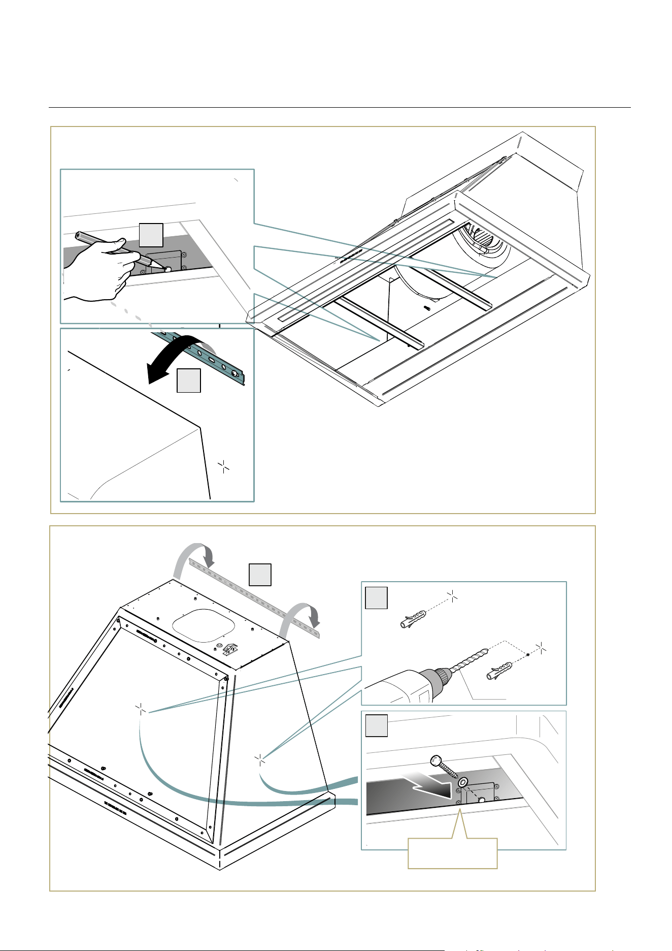
INSTALLER
INSTALLATION
STEP 4
STEP 5
1
2
3
2
1
NON FORNITA
NOT PROVIDED
ø8 mm
ø 0
5/16”
22
INSTALLATION
STEP 6
1
2
appoggiare la cornice
fissare con le apposite viti
dall’interno della cappa (x7)
place the frame
x with the appropriate screws
from inside the hood (x7)
23
INSTALLER
INSTALLATION
STEP 7

24
IMPORTANT SAFETY WARNINGS
The installation and extraordinary maintenance operations
must be carried out by qualied personnel, authorized by
the Manufacturer, having the necessary product
knowledge, and in compliance with the regulations in
force in the Country of use regarding the types of systems
involved and safety in the workplace.
Before connecting the device to the mains, please check
that all connection data on the product label (voltage
and frequency) match those of the mains (Refer to
chapter “How to read product label” on page 27 for
further information on the data plate). Please note that
any incompatibility could lead to serious damage to the
device, so always contact a qualied electrician before
installing your hood; check that the systems comply with
the regulations in force in the Country of use; always
compare the system data with that printed on the data
plate;
check all the components for integrity and functionality: in
case of fault, stop the installation and contact the
distributor.
Do no connect the product to the power main before any
other step of the installation is completed;
Any interventions, tampering or modications not
expressly authorised, not complying with the content of
this manual, will void the warranty, and may also cause
immediate danger or dangerous situations that may
result in injury or even death.
During the installation of the equipment, anyone not
responsible for carrying out installation
activities must refrain from transiting or stationing in or
nearby the installation area.
Being potentially hazardous, packaging materials must
be kept out of reach of children or animals, and must be
correctly disposed of, in accordance with local
regulations.
During the installation activities, always use the required
personal protective equipment (e.g. safety shoes) and
act with the due level of care and attention.

25
INSTALLER
The fastening kit (screws and plugs) supplied with the hood
can only be used on masonry wall. For installation on other
types of walls consider alternative fastening systems,
taking into account the strength of the wall itself and the
weight of the hood.
To perform the installation and ensure the best solidity of
the whole framework, always use the the securing devices
and the components (e.g. screws, bolts, brackets, etc.)
provided with the packaging;
In order to prevent any loss in the product efciency and
safety of use, the hood should be installed indoor only,
sheltered from weathering (i.e., rain, wind) and harsh
environmental conditions (dried salt, extreme thermal
excursion);
Do not change the electrical, mechanical and functional
structure of the equipment.
The electric connection socket must be easy to reach
even after installation of the equipment.
Should this not be the case, a general switch must be
installed, in order to disconnect the
hood from the power supply in case of need.
The maximum weight of any objects placed on top of the
hood or attached to the same should not exceed 2 kg
(4,4 lb).
The air must not be discharged into a ue that is used for
exhausting fumes from appliances burning gas or other
fuels.
Do not hang on the equipment, and do not use it as a
support for other objects or cabinets.
Any variation or operation in the electrical system should
be performed exclusively by a qualied electrician;
Do not repair the hood by yourself nor replace any of its
components, except for the antigrease and the carbon
lters. Repairs and other work performed by unqualied
personnel will nullify any warranty right on the product, and
could lead to product failure and damage to people or
property.
IMPORTANT SAFETY WARNINGS
26
PRELIMINARY
INSPECTION
After opening the package, please inspect the equipment
for any possible damage that could have occurred during
transport. If the product is damaged, please take note of
the data printed on the product label (Fig. 3.) and promptly
notify the data to your Supplier.
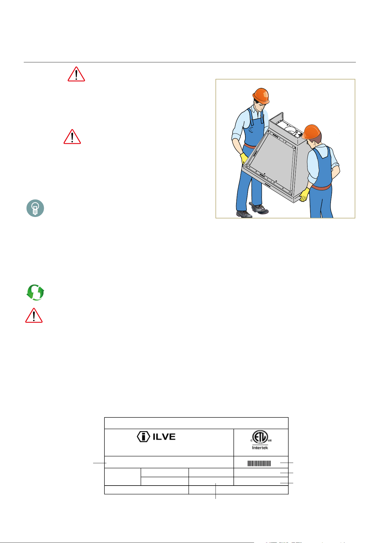
TRANSPORT
The transportation, loading and unloading of the product
should be performed by personnel wearing all the neces-
sary protections (Fig. 1.). When handling the equipment,
implement all the necessary precautions to avoid damage
to the same or to people and property, complying with the
instructions found on the packaging.
When handling the equipment, always use clean
cotton gloves to avoid ngerprints.
FIRST-USE PREPARATION
After the hood installation, please remove the protective
lm and carefully clean the external surface (Fig. 2.). Please
note that the use of acid-based cleansers could damage the
hood surface, so use a neutral or a steel-specic cle-
anser only.
All packaging and the protective lm must be
disposed of in accordance with the regulations of the
country of use. Always make sure that nothing is
disposed of in the environment.
Packaging materials may be potentially dangerous
for children and animals.
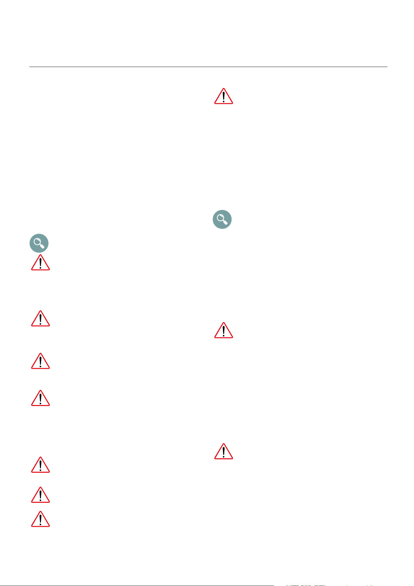
HOW TO READ PRODUCT LABEL
The product label is located inside the hood, usually
attached on its bottom, being visible after the removal of the
anti-grease lters. The label shows essential data and informa-
tion about the product regarding installation, customer service
and warranty-related repair, as well as instructions to determine
the correct spare parts for the specic model. Please do not
remove, damage or alter in any way the product label, since
this could impede the Manufacturer from identifying the pro-
duct in case of need.
INSTALLATION
Fig. 1.
Fig. 2.
Manufacturer:
Via Antoniana, 100
Fabricant:
35011 Campodarsego (PD) Italy
Tel. +39 049 9200990
Fax. +39 049 9201010
Model
Modèle
UANB36
Serial N° CC040030
Electric rate Voltage: 110-120 V Frequency: 60 Hz Max electric power: 368W
:xaM ecnassiuP:ecneuqèrF:noisneTerbilaC
Max electric current: 3,2 A
Motor: 1000m
3
/h
Lamp: 1x15W
Courant èlectrique Max: Moteur: Lampe:
Conforms to UL STD 507 Certied to CSA STD C22.2 # 60335-1
13-2-53306 # 2.22C DTS ASC à éifitreC emron al à emrofnoC
5023161
Electric range hoods
Hottes de cuisine
Hood model
Total power
Type of illumination
Hood serial number
Type of motor
27
INSTALLER
CORRECT POSITIONING
The hood should be placed at a minimum distance of
65 cm for the wall-mounted models and 75 cm
for the island/roof models. It could be that Your
specic hob requires the range hood to be placed at a
greater distance: always refer to the manufacturer’s in-
structions handbook for further information.
The installation site must:
- be well ventilated and not exposed to weather condi-
tions;
- Have a temperature between +16 e i +32 °C
(90°F) and an humidity below 60% (any variation from
the aforementioned values could accelerate the usual
decay time of the carbon lters decay or limit the overall
performance of the hood);
- comply with all the applicable regulation from the User’s
country in terms of indoor air quality, electrical system
security and work safety;
- be suitable for the preparation of food.
For correct installation, refer to the drawings on
page 16 to 24.
The equipment must be installed in a way that
ensures easy access to electric connections.
Do not use any electric wire or other electric devices
to extend the original power cord. Please inspect the
existing wall sockets or power cords of your kitchen and
place the hood accordingly;
The fastening kit (screws and plugs) supplied with
the hood can only be used on masonry wall. For
installation on other types of walls consider alter-
native fastening systems, taking into account the
strength
of the wall and the weight of the hood.
Do not place the equipment near ammable
materials or ammable substance containers
(e.g. partition walls, gas cylinders, etc.), to
avoid re hazards.
All the installation operations, assembly, con-
nection to the electric power supply and extraor-
dinary maintenance must only be carried out by
qualied personnel, authorised by the Distributor
or Manufacturer, in accordance with the legal
requirements of the country of installation and in
compliance with equipment and workplace sa-
fety regulations.
The equipment must only be installed by respon-
sible and experienced adults, without physical
impairment and in perfect psychological and
physical condition.
During installation, anyone and any objects not
involved in the assembly operations must be kept
away from the area.
Before starting the assembly operations, make
sure that all the necessary tools are available
and in good working order.
ELECTRIC CONNECTION
The electric connection can only be carried
out by qualied personnel (electrician).The
cable and the internal hood cables must
not be replaced or modied.
Before connecting the equipment to the power
mains:
- read the safety instructions provided at the
beginning of this manual;
- make sure that the electric system installed complies
with the local regulations of the country of installation;
- make sure that the electric system installed is suitable
for the characteristics of the equipment being installed
(see the details on the data plate).
Refer to chapter “How to read product label” on
page 27 for further information on the data plate.
The equipment is supplied with the power supply cable
already attached: connect a suitable plug for the load to
the cable (the plug must comply with current standards).
Remember the following:
- yellow- green cable: earth;
- blue cable: neutral;
- brown cable: phase.
Always install a circuit breaker for quick discon-
nection.The earth cable must be not interrupted
by the circuit breaker.
If the power cord is faulty, it should be replaced with
another one with identical features. To prevent all kinds of
risks, such replacement must be carried out by the Ma-
nufacturer, its technical support service, or in any case
by a similarly qualied individual. The Manufacturer is not
liable for any damage resulting from the use of unautho-
rized or aftermarket spares.
Before any interventions inside the hood, disconnect the
electric power supply.
Avoid winding the cable on itself if too long. Make
sure that the cable is not in contact with liquids,
sharp or hot objects (temperatures exceeding
>70°C ), or corrosive substances.
INSTALLATION
28
cappa ad
evacuazione
esterna
vapori
fumi e
fumi e
vapori
cappa
a ricircolo
interno
metallici
metallici
carbone
attivo
fumes and
steam
INSTALLATION
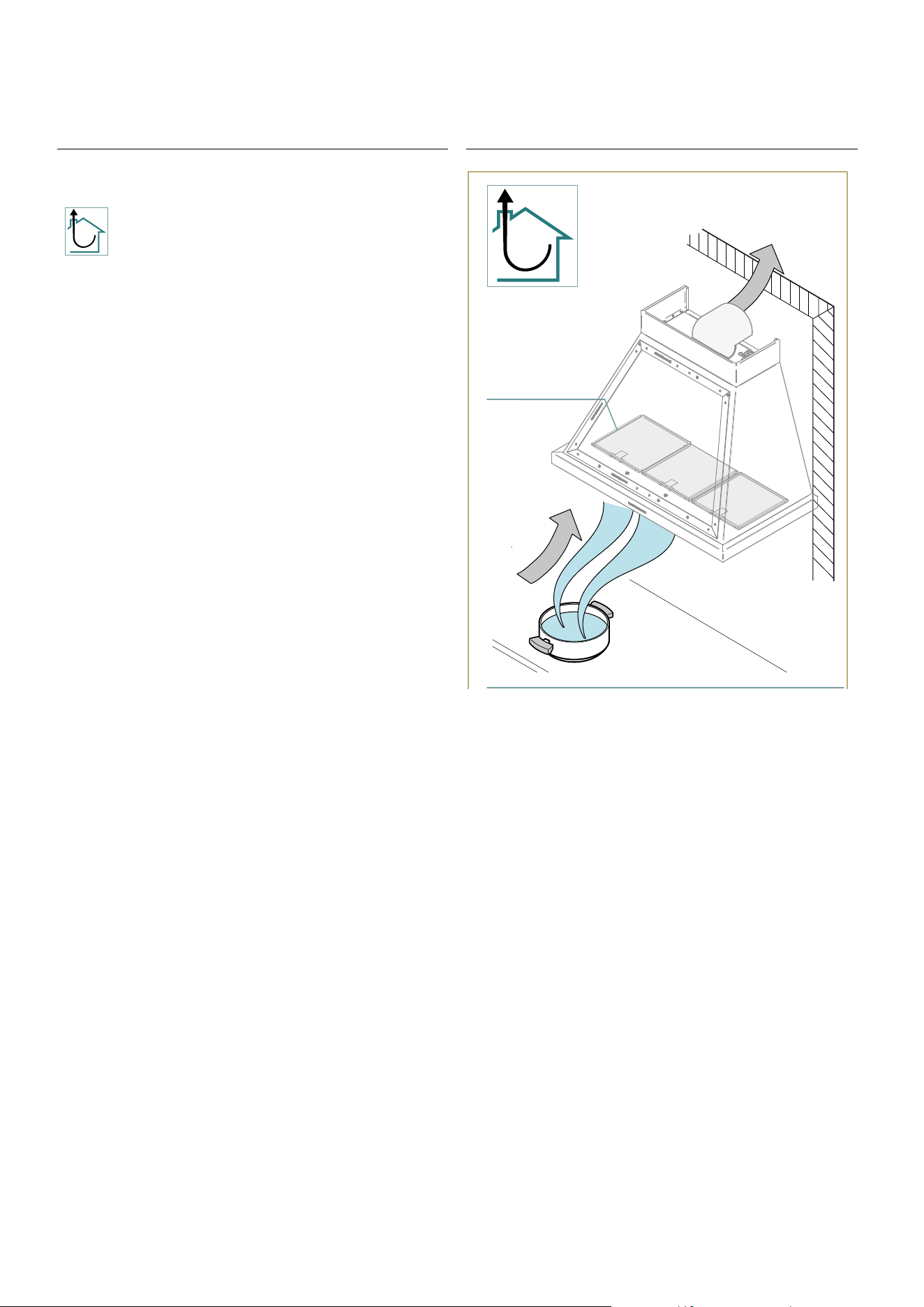
FUME EXHAUST CONNECTION
DUCTING/SUCTION VERSION
This type of hood is equipped with a top air outlet for
discharge
of fumes outside the house, which has to be connected
with the inlet of the building chimney, commonly
through a hose (not provided).
Horizontal tube sections must be slightly tilted upwards,
to help channelling of the air to the outside. Fume di-
scharge tubes crossing particularly cold environments
(e.g. attics) should be insulated, to prevent condensation
caused by temperature differences.
Suction type hoods DO NOT require carbon lters, which,
on the contrary, can limit their performance.
Any changes to the tube, sudden diameter reductions,
and bends, may prevent the hood from reaching opti-
mum suction capabilities, and may jeopardise the ope-
ration of the motor, relieving the Manufacturer from all
responsibility.
Make sure that the ue is in perfect working order, and
that a square (concrete) or round (metal) static wind
break ventilation tower with useful output section not less
than double the diameter of the ue (UNI 7129) is instal-
led at the top of the ue itself.
external
evacuation
hood
metal
lters

NOTE

30
NOTE