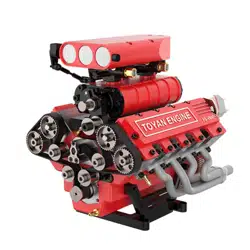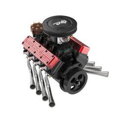
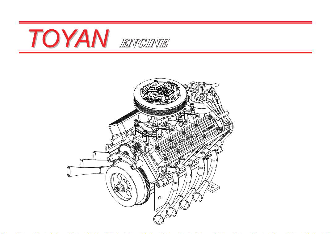
FS-V800WGPC
OPERATING MANUAL
Thank you for Choosing our products,Model
FS-
V800WGPC is one accessories kit with Precise
Eight Cylinder Four-stroke model engine,. Before assemblying and operating your engine, please
read the "safety instructions and warnings" section on pages 2-3 of this booklet and contents of
accessories assemblyl,to strictly adhere to the advice contained therein
>Also,Please study the entire contents of this instruction manual,so as to familiarize yourself with
engine controls and other functions.
>Furthermore,
Keep these instructions in a safe place so that you may readily refer to them
whenever Necessary
13~43
04~12
02~03
46~48
44~45
49~52
53~54
54
55
56
58
59
60~62
57
Three Views
Multi-view
Safety Introduction and Warnings
Product Introduction
Product Assembly Steps
Wiring Diagram
Precautions for Startup
Stable Operation and Adjustment
Regular Cleaning and Maintenance
Replacement of Operating Components
Troubleshooting Methods for Engine Failure to Start Normally
Exploded View
Commitment
Part List
CATALOGUE
SAFETY INSTRUCTIONS AND WARNING
2
S
Remember that your engine is not a "toy", but a high-efficiency internal combustion engine, the
output power may cause you harm, or other effects, do not change or disassemble
The advice which follows for all production engines ,Incorrect operation or Ignore safety can
lead to engine damage or dange
As a professional user, please make sure the engine runs safely and carefully.
If at some future date, your
FS-V800WGPC
is acquired by another person, we would respectfully
request that these instructions are also passed on to its new owner.
r
Warning: These cover events which might involve serious (in extreme circumstances, even fatal )injury.
Model engine fuel is poisonous. Do not allow it to come into contact with the eyes or mouth.
Always store it in a clearly marked container and out of the reach of children.
Model engine fuel is also highly flammable. Keep it away from an open flame, excessive heat, sources
of sparks, or anything else which might ignite it. Do not smoke or allow anyone else to smoke, nearto it.
Never operate your engine in an enclosed space. Model engines, like automobile engines, exhaust
deadly carbon-monoxide. Run your engine only in an open area.
Model engines generate considerable heat. Do not touch any part of your engine until it has cooled.
Contact with the muffler,cylinder head or exhaust header pipe, in particular, may result in a serious burn.
3
This engine was designed for science experiments, model demonstrations, model car drives. Do not
attempt to use it for any other purpose.
Mount the engine in your model securely, following the manufacturers' recommendations, using
appropriate screws and locknuts.
Noise will happen when starts, please buy our matching muffler exhaust pipe or run away from the
living environment, because the noise of the operation may irritate others.
Safety glasses are strongly recommended.
Please note that the electric plug or battery wire should not touch the rotating parts. Also check
whether the connection of the throttle rocker arm is firm.
Tobe safe, keep all spectators (especially children) at least 3 meters away from engine when start the
engine.
If you want to stop engin, shut off the throttle completely. In an emergency, clamp the fuel line in front
of the carburetor to cut off the fuel supply
Do not attempt to remove the flywheel and start the synchronous pulley
Do not extend the starting battery wire by more than 20cm. Otherwise, the starting current will be
insufficient due to the resistance voltage drop inside the battery line
When starting the engine, please do not press the start button for a long time. The maximum starting
time is 5 seconds. If it does not start, please stop for 15 seconds and press the button to start again,
so as not to burn the starting motor and ignition circuit due to the long starting
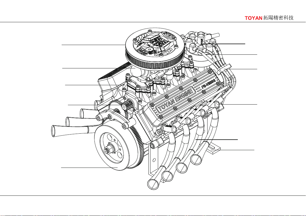
Intake duct
Air filter
Power distributor
Cable
Cable buckle
Spark plug
Driving gear
Exhaust pipe (left)
Bracket
Carburetor
Flywheel
4
INTRODUCTION
engine structure and components
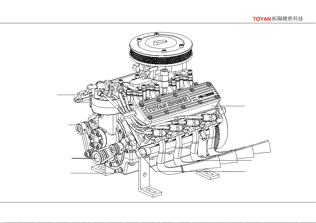
Cylinder head cover
Cable buckle
Water pump pulley
Crankshaft pulley
Waste oil nozzle
Exhaust pipe (right)
Water pipe connector
5
INTRODUCTION
engine structure and components
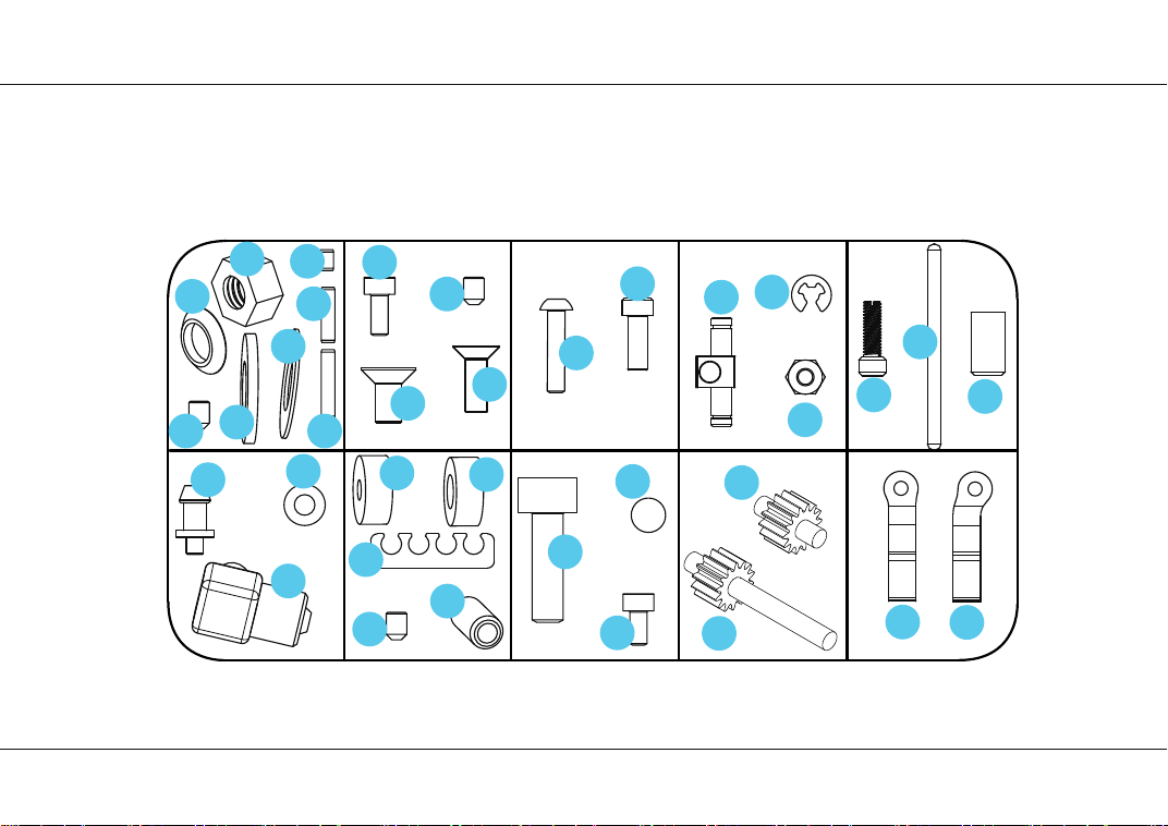
Φ3×6×0.5
M3×4
M5×16
8
20
M3×4
8
M3×4
8
3
4
5
27
17
32
33
2
1
21
M2.5×6
M4×6
M3×8
M2.5×10
9
小头
M3×8
13
12
M2.5×5
29
6
7
10
11
26
23
24
22
25
28
18
19
15
16
14
31
30
TOYAN
拓陽精密科技
6
Distribution diagram of parts packaging
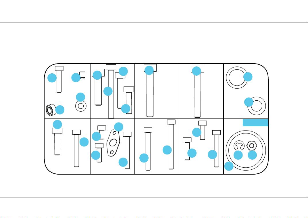
M3×4
8
M2.5×16
45
M4×16
37 M4×20
41
M4×20
41
M2.5×12
M2.5×16
34
M3×12
44
M3×12
40
39
38
Φ3×5×0.5
36
35
备用零件
M2.5×8
47
M2.5×16
M2.5×8
47
M2.5×10
50
M2.5×5
29
46
45
M3×30
M3×20
42
43
15
16
51
45
M2.5×25
49
M2.5×20
48
TOYAN
拓陽精密科技
7
Distribution diagram of parts packaging

TOYAN
拓陽精密科技
8
52
55
57
54
56
58
60
61
62
63
64
65
66
67
68
69 70
71
72
59
53
Distribution diagram of parts packaging

TOYAN
拓陽精密科技
9
73
74 75 76 77
85
86
87
88
89
90
78
79
80
81
82
83
84
Distribution diagram of parts packaging

TOYAN
拓陽精密科技
10
91 92
93
94
95
96
111
Distribution diagram of parts packaging

TOYAN
拓陽精密科技
11
98
97
99
Distribution diagram of parts packaging

TOYAN
拓陽精密科技
12
100 101 102 103
104
105
106
107
108
110
109
Distribution diagram of parts packaging
13
Completion
diagram
Pay attention to using lubricating oil during installation
52
45
54
55
59
77
Product assembly steps
14
Attention!
When disassembling, it
is necessary to maintain
the original pairing and
not confuse it. During
installa-tion, the
concave points at the
arrow should also be
kept corresponding.
Step two
Product assembly steps
Step one
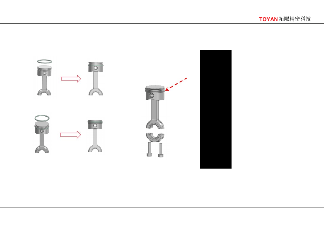
The openings of the two piston rings
should be separated by 180 degrees,
and the opening of the
piston ring
should not be in the position
corresponding to the piston pin.
The piston ring is inside the cylinder liner; when installing, do
not use force and do not deform the piston ring; after the
piston ring is installed, it should be installed in the
corresponding cylinder liner. It is matched one-on-one. Please
don't make a mess!
5
58
97
Cylinder
identification
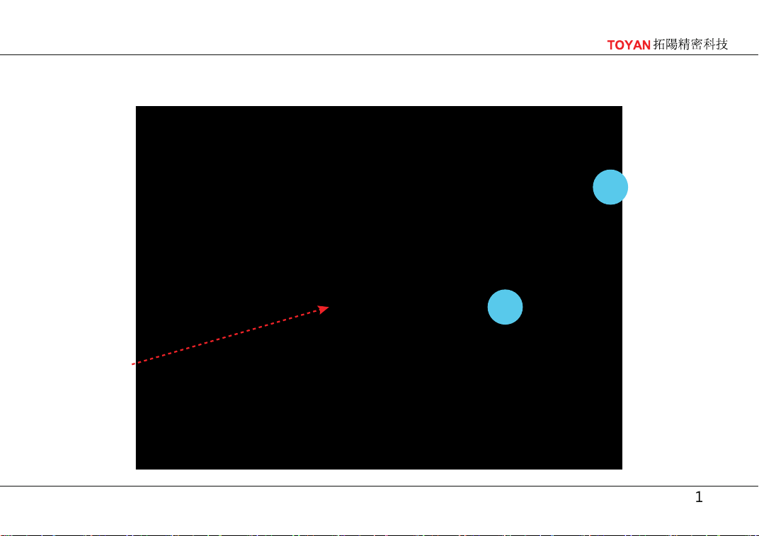
Use the piston ring sleeve to install
the upper half of the connecting
rod with the piston into the cylinder
block, paying attention to the use of
lubricating oil
Product assembly steps
Completion
diagram
16
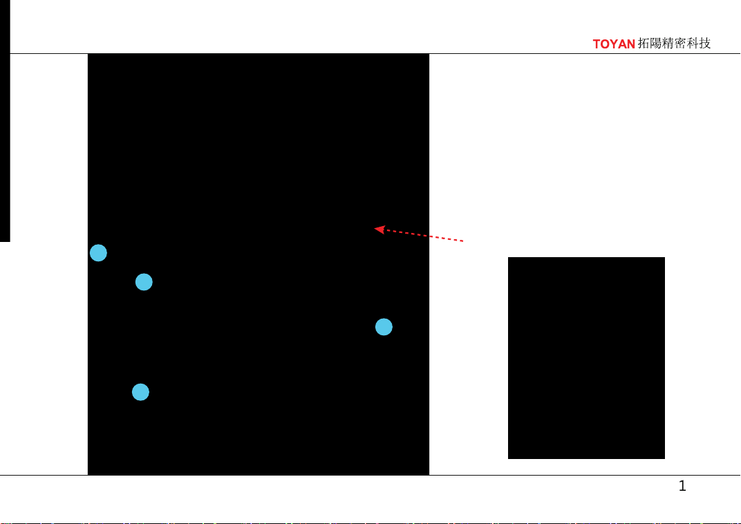
Install the remaining
lower half. Pay atten-
tion to the correspon-
dence between
convex points. Pay
attention to using
lubricating oil
Product assembly steps
Seal the groove position with glue
7
20
44
53
21
Product assembly
steps
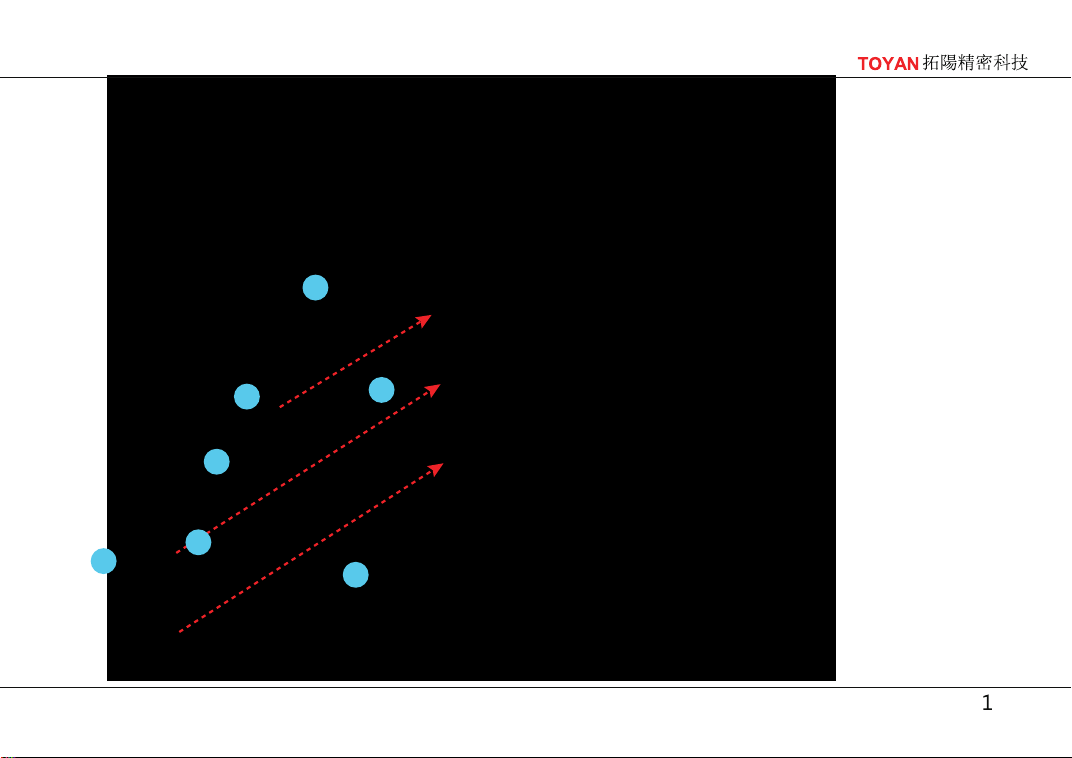
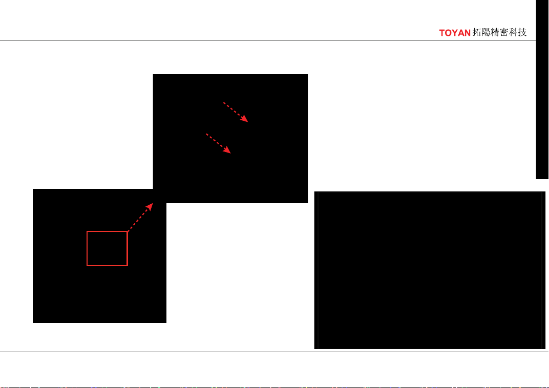
*After installing the 82 # oil seal into the
73 # cylinder cover plate, press down on
the 108 # gasket in the direction of the
arrow and secure it with 10 11 # screws
*Press the 78 # motor bracket
against the 107 # gasket in the
direction of the arrow and
secure it with 4 10 # screws
8
11
82
73
10
78
107
108
Product assembly steps
50
71
19
Product assembly steps
75
3
20
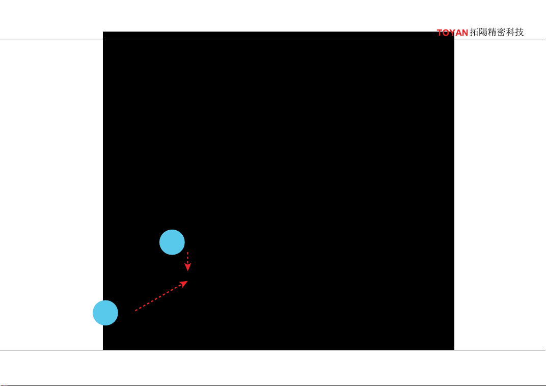
*Place the 3 # cylindrical pin
in the groove in the direction
of the arrow, and then install
the 75 # gear, paying atten-
tion to installing the side with
dots on the outside
Product assembly steps
93
8
76
24
62
21
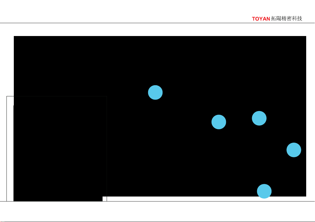
*First install the 24 # bearing, then install the 76 # gear, paying attention
to the side with dots being installed on the outside and in the direction
of the camshaft D-groove. Then install the 62 # gear and the 8 # screw,
using screw glue for the 8 # screw
Direction of camshaft D-groove
Product assembly steps

22
*Insert the camshaft into the
cylinder block, use lubricating oil
during installation, and pay
attention to the gear meshing
state after installing the camshaft
*At this time, the first
cylinder is in a
working state
Product assembly steps
47
45
82
6
23
109
*Insert the 82 # gasket onto the
crankshaft, press the 47 # distributor
housing against the 109 # gasket in
the direction of the arrow, and
secure it with 9 47 # screws
*2 45 # screws on
the opposite side
Product assembly steps
28
19
18
24
Product assembly steps
41
92
25
101
41
91
100
Product assembly steps
完成图
26
12
79
17
16
32
32
33
33
15
14
*First, install 17 # on the 32 # intake
rocker arm and 33 # exhaust rocker
arm respectively. After installing the
16 # nut, install the rocker arm on the
14 # rocker arm frame, and then
install the 15 # retaining spring
Product assembly steps
27
13
*Fix the rocker arm bracket assembly with 13
# screws and adjust the valve clearance with
16 # nuts, ensuring that there is at least
0.1mm clearance between each rocker arm
and valve
Product assembly steps
28
57
8
*After inserting the 57
# component, tighten
it with the 8 # screw.
Lubricating oil is
required for the gear
during installation
Product assembly steps
29
30
31
Product assembly steps
70
69
34
34
30
110
30
31
110
30
31
Product assembly steps
31
106
47
26
23
74
Product assembly steps
32
87
9
8
64
Product assembly steps
33
64
37
66
36
36
65
39
6
4
67
*First, place the 36 # gasket and 66 #
gear above, while installing the 6 #
gasket and 4 # pin on the crankshaft.
Then, install the 67 # gear. The outer
gear of 66 # meshes with the 64 #
gear, and the smaller inner gear
meshes with the 67 # gear
*The 39 # screw passes through the
65 # part, 36 # gasket, 66 # gear, and
36 # gasket in sequence. Two 37 #
screws pass through the 65 # part and
are finally fixed on the cylinder block
Product assembly steps
34
1
7
5
68
2
Product assembly steps
45
47
80
84
81
86
43
35
103
104
*2 45 # screws on
the opposite side
Product assembly steps
72
60
61
8
36
*Pay attention to distin-
guishing between the 60
# and 61 # directions,
and use 8 # screws to fix
the pulleys,using screw
glue for the 8 # screw
Product assembly steps
90
89
40
38
36
63
37
35
83
Product assembly steps
27
56
38
105
Product assembly steps
42
29
85
39
*
Disassemble the 85 #
component, fix it to the
carburetor with two 29 #
screws, and then reassemble
it, being careful not to miss
the 42 # O-ring
Product assembly steps
49
42
48
40
102
*Before perform-
ing this step, add
lubricating oil to
the rocker arm,
tappet, and other
parts, and fix the
cylinder head
cover on the other
side using the
same operation
Product assembly steps
22
*Use the same
operation to fix
the water pipe
connector on the
other side
41
Product assembly steps
96
46
29
95
42
Product assembly steps

43
111
25
*Install the cables and cable
buckle, and assemble them
Product assembly steps
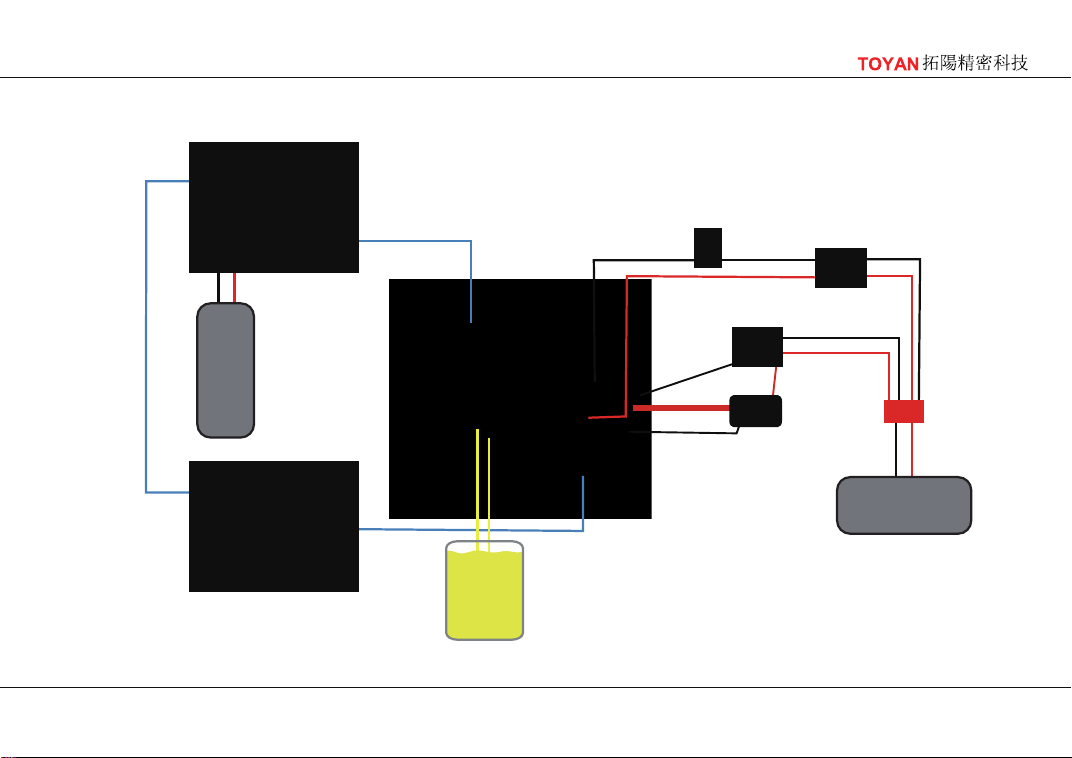
Wiring diagram
44
*Connect the cable corresponding to
the number on the distributor to the
corresponding cylinder。
*Firing Order 1-5-4-3-6-8-7-2
*To avoid affecting the discharge
effect, solder the ignition wire with
a soldering iron.
Attention!
Switch
Water inlet
Water outlet
Li
11.1V-3S
Row output
transformer
Relay
CDI
Li
11.1V-3S
Water cooled
radiator
Water tank
Fuel
Wiring diagram
45

TOYAN
拓陽精密科技
46
INSTALL THE BASE
Make sure the surface of engine mounting is flush and in the same flat. Improper
installation may lead to deformation of crankcase, bearing, etc. Unstable operation and
performance degradation will happen. The 4.0mm hexagon socket screws are recom-
mended when fixed engine. If installed on other engine platforms, please purchase
adjustment pads to fit between the engine bracket and the engine.
ATTENTION ABOUT STARTING
For the sake of safety, it is strongly recommended not to disassemble the engine and start the
mechanism. If any starting problems, please contact your local dealer or
TOYAN
TOYAN
technician to solve
them. If return to the factory for testing, will provide you with high-quality after-sales service.
If any problem caused by unauthorized disassembly, you will bear the corresponding responsibilities
and expenses
1 Spark Plug
Model FS-V800WGPC requires 8 special spark plugs for a four-stroke gasoline engine.The spark
plugs require a special CDI for ignition control. when hall detects display the piston running to the
TDC, spark plug will be ignited, fuel will be ignition,then generate will acting.

TOYAN
拓陽精密科技
47
2.Fuel
Please use gasoline engine fuel with guaranteed quality. Self-matching or fake fuel will greatly
reduce the performance and life of the engine. As it is a four-stroke engine, in order to ensure
the normal operation of the primer, please adjust the ratio of gasoline and fuel in the range of
1:25 to 1:30, and the oil uses 2T internal combustion engine oil.
Remind!
3.Fuel tank
If the engine is running at very high speeds and on high nitro fuel,The life of the spark plug
does not last long. Please note that engine fuel is toxic. Keep it out of contact with eyes or
mouth and always store it in a clearly marked container and place, and keep out of reach of
children. It is highly flammable. Keep away from open fires, overheating or any source of
ignition
It is recommended to use a 100cc tank. The tank should be installed on the same flat as the engine.
The gap between the fuel inlet & outlet of the fuel tank and carburetor should be kept within 1 cm
(the carburetor must be higher than the fuel inlet & outlet of the fuel tank). If the gap is too high,
the carburetor's working efficiency will be reduced and the engine will be started adversely. To
ensure clean fuel supply, pls use standard 5mm silicone tubing and properly install oil filters. Since
the engine itself relies on negative pressure to absorb oil, it is recommended the muffling exhaust
pipe can be used to pressurize the fuel tank

TOYAN
拓陽精密科技
48
4.Start power supply
5.Environment for starting
Model FS-V800WGPC requires a standard 11.1V 3S lithium battery, which can be quickly started
after connected. Too low or too high voltage of starting battery will not guarantee the service life
of the starting motor.
Please start the engine in an open, airy environment to avoid discomfort from burning gases
6.Platform for Starting
Since the engine will produce some vibration after starting, please place it on a stable and flat
platform

TOYAN
拓陽精密科技
49
OPERATION AND ADJUSTMENT
Note
Four-stroke engines have stronger torque output than two-stroke engines, so the
corresponding measures should be taken during operation
1. Check the timing belt and CAM axle box
Please make sure that the marking points on the two pulley can be down at the same time,see P43.
Open the hood and add the grease. Since the mounted CAM is used, please add the solid grease to ensure
stable operation and avoid dry friction of the CAM.
In order to extend the service life and improve the performance, each engine has been tested at
the factory. You need to do proper running-in and cleaning after receiving the engine. After
continuous running in, the cylinder pressure will be gradually strengthened. Due to the high
simulation degree of this engine and the large number of various parts, we do not recommend
you to fully disassemble the engine, we will provide a variety of effective sales to help you
maintain and stable use
2. Check the power supply
Please confirm that the voltage of 11.1v universal ignition power supply is normal, and full
of electricity
3. Initial Oil Needle Setting
The prerequisite is adequate lubrication and cooling. The engine is run with very important oil
needle settings: The excess oil not only provides rich lubrication, but also conducts heat from
the surrounding metal and further assisted by the fuel nitro methane. the two-stroke model

TOYAN
拓陽精密科技
50
engines in pre-heating into the cylinder through the crankcase on a longer trip. But The
four-stroke engine, with its intake pipe and carburetor mounted high on the cylinder cap, means
that the rich mixture of cooling fuel and air will flow directly into the cylinder directly.With the
help of fan cooling, it can provide excellent operation experience for every enthusiasts. You can
also buy the
TOYAN series of water cooling accessories, so that your engine will be able to
maintain stable operation for a long time.
Remind!
When leaving the factory, each engine has completed the oil needle setting. If you have
misadjusted the oil needle during the use, it is recommended to adjust the main oil needle
to 2.0 laps and the auxiliary oil needle to 1.5 laps. Since the methanol engine needs to
maintain the temperature of the spark plug filament to achieve ignition, when the engine is
in the oil rich state for a long time at low speed, the temperature of the filament will
gradually reduce, resulting in ignition difficulty. Therefore, it is necessary to up the speed
for cleaning oil at intervals to avoid oil enrichment at low speed

TOYAN
拓陽精密科技
51
4. Start
Remind!
It is important to put the throttle in the right position before starting the engine. It is
recommended that the throttle be opened at 30% to start, the engine is not allowed to open
the throttle too far under "no load" conditions, which can quickly overheat and can seriously
damage the engine piston ring and cylinder sleeve.
Connect the spark plug battery and press the start button. Once the engine starts,
disconnect the spark plug battery and keep the engine running slowly under the oil-rich
needle setting. (If necessary, gently adjust the throttle lever to keep the engine idle steady.)
If the engine stops, cooling it for 15 seconds before restarting. Please hold down the start key
within 5 seconds for each start, so as to protect the start motor life. Allow the engine to warm
up for 30 seconds after starting so that the oil in the fuel can be fully lubricated to each working
part. When the engine rapidly drops from high speed to low speed, or when low speed rapidly
rises to high speed, the engine is unstable or the throttle control is slow or flashover, please
confirm the carburetor working status

TOYAN
拓陽精密科技
52
Rich oil
Lean oil
Idling Stop
When the engine has more fuel , smoke is emitted or accelerates slowly, indicating that the
engine has excessive oil, please turn the main oil needle clockwise, 15° as a unit, gradually
reduce the main oil needle, until the sound of engine exhaust is soft and strong, and the
exhaust pipe slightly smokes and the lubricates fuel spray out
If the sound of the engine is too sharp, like the sound of dry friction between metals, the
temperature rises rapidly, and the engine is stopped immediately after acceleration, indicating
that the engine has low oil, please turn the main oil needle counterclockwise, 15° as a unit,
gradually reduce the main oil needle, until the sound of engine exhaust is soft and strong, and
the exhaust pipe slightly smokes and the lubricates fuel spray out
When the engine speed changes rapidly, suddenly adjust from the high speed to the low
speed, the flameout occurs, please confirm whether the throttle is closed less than 1.5mm, or
gradually reduce the auxiliary oil needle, (clockwise rotation) gradually adjust the auxiliary oil
needle, 20°as units, until the engine maintains a steady idle speed. In the debugging process,
the auxiliary oil needle should not be excessively reduced, so as not to cause engine have lean
oil, we recommend that the minimum value of auxiliary oil needle should not be less than 1
turn.

TOYAN
拓陽精密科技
53
CARE AND MAINTENANCE
The series of FS-V800WGPC is a very precise machine that you need to clean timely. Due to the
impact of environment and the fuel when using, the engine parts have a certain amount of wear
and corrosion.So, TOYAN will also provide you with long-term maintenance services. You can
also complete the basic cleaning and maintenance
Carefully clean the carburetor and remove dirt and grease from the inlet
If an air filter is used, make sure the filter is clean and free from blockage
Recommended that the air core used for more than one hour should be replaced in time.
Be careful to remove contaminated filter elements to ensure that dirt does not enter the
carburetor
Do not remove timing synchronous belt, you can use alcohol as a cleaning agent to wipe the belt. Do
not use corrosive detergent to clean synchronous belt, to avoid damage
Glow Plug must be treated as consumables. Long running glow plug will not ensure the normal operation
of the engine and you can extend its life maintain the performance of the engine if you use it carefully,
Use appropriate tools for disassembly
Use fuels containing a moderate percentage of nitromethane
Do not overtilt the engine and do not connect the battery while adjusting
The time to replace the glow plug. expect burned, It also need to be replaced on these situations because
it no longer provides optimal performance,
For example:
a.The surface of the filament becomes rough and white
b.Filament curl deformation

TOYAN
拓陽精密科技
54
c.External material adhered to the filament or plug corrosion
d.The engine will power off when idling
e.The power went out after the engine started
Note!
These maintenance programs will be stored after a period of time, and there is a risk of
corrosion or startup difficulties, if you need someone to deal with, please contact us
Replacement of running parts
At the end of each operation, empty the fuel tank, energize the glow plug, and try to
restart the engine to burn the possible left fuel in the fuel tank. Repeat this process until
the fuel is cleared from the engine.
Inject some antiseptic oil and briefly start the motor to distribute the oil to the working
parts. Do not inject this oil into the lubricator nozzles, as this may cause the O ring of the
carburetor to deteriorate Add solid lubricant to camshaft and valve tappet to ensure that
the CAM axle box has enough lubricant for each operation
After long-term operation, the friction between the engine components will cause wear and
too large gap, the replacement of related parts will help you maintain your engine better.
When you are in the process of use, there is not flexible start, power reduction, idle speed
instability and so on, please feedback your usage process and poor performance of the
engine to the local dealer or , we will serve you wholeheartedly. Parts replacement, we
will provide professional equipment and experienced team. Please do not disassemble the
engine without professional tools to avoid the risk of uncontrollable damage to the engine
TOYAN
TOYAN
拓陽精密科技
55
BUG CHECKING
If the engine fails to start, check the following carefully:
Whether the battery voltage is normal, whether the power is full
Whether the glow plug has failed
Whether the fuel can reach the carburetor smoothly
Do not start the engine when it is flooded. Remove the glow plug, close the oil needle and
press the start button to drain the excess fuel. (Cover the plug hole with a piece of woolen
cloth so that the fuel doesn't spill on you.) If forced to start without removing the excess
fuel, it may cause irreversible damage to the starting system, as well as the connecting
rod and crankshaft to strain and deformation
Timing belt adjustment
All TOYAN Motor have been tested for timing belt position before they leave the factory.
After several hours of execution, the operating power loss or engine running instability is
found, the timing belt needs to be tested and adjusted to get the correct ignition information
for the engine. Please check against page 11 of "timing belt timing diagram"
When Turn off at low speed, do not keep it at too low speed a long time. Since the methanol
engine needs to maintain the temperature of the spark plug filament to achieve ignition,
when the engine is in a rich state for a long time at a low speed, the temperature of the
filament will gradually decrease, resulting shutdown. Therefore, it is necessary wait a while to
up the speed oil and clean the oil to keep the temperature of the filament
56
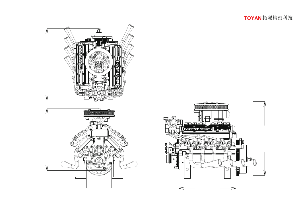
FS-V800WGPC Specification
·Displacement:3.5cc×8
·Bore: 16.60mm
·Stroke: 17.00mm
·Practical rpm: 2500-10000rpm
·Output: 3.80ps(30%Nitro)
·Weight: 2.4kg
Three
Views
177.50
118.0058.00
140.50
152.10
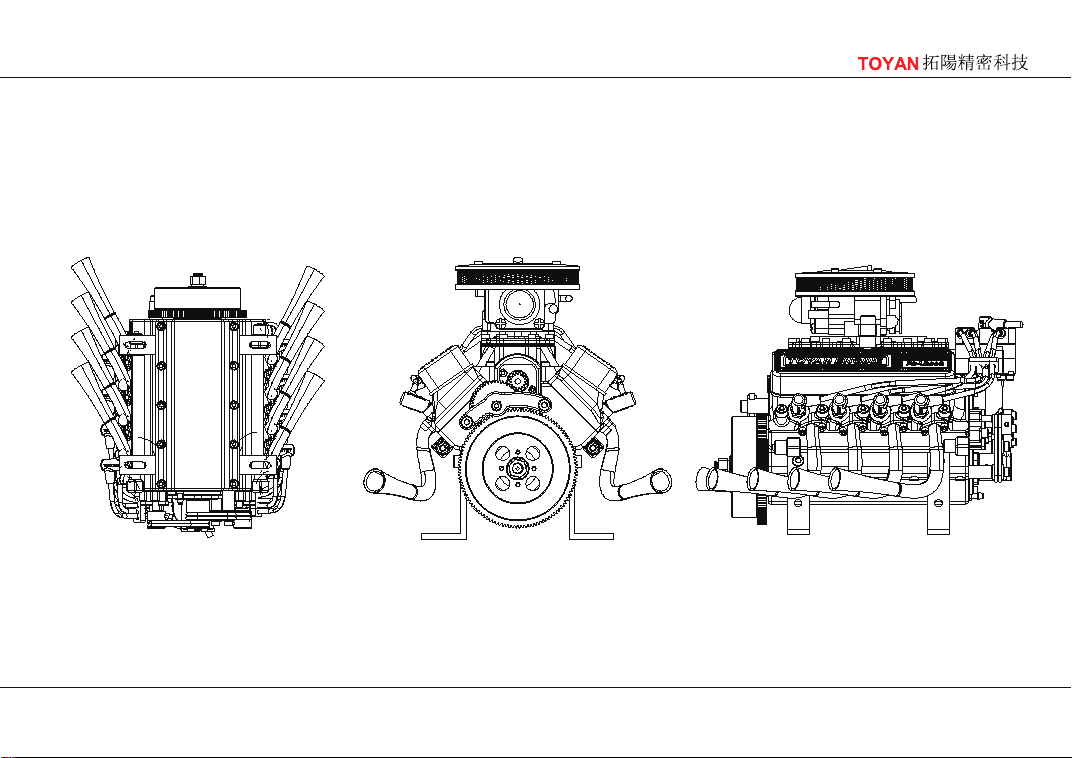
57
Multi-view
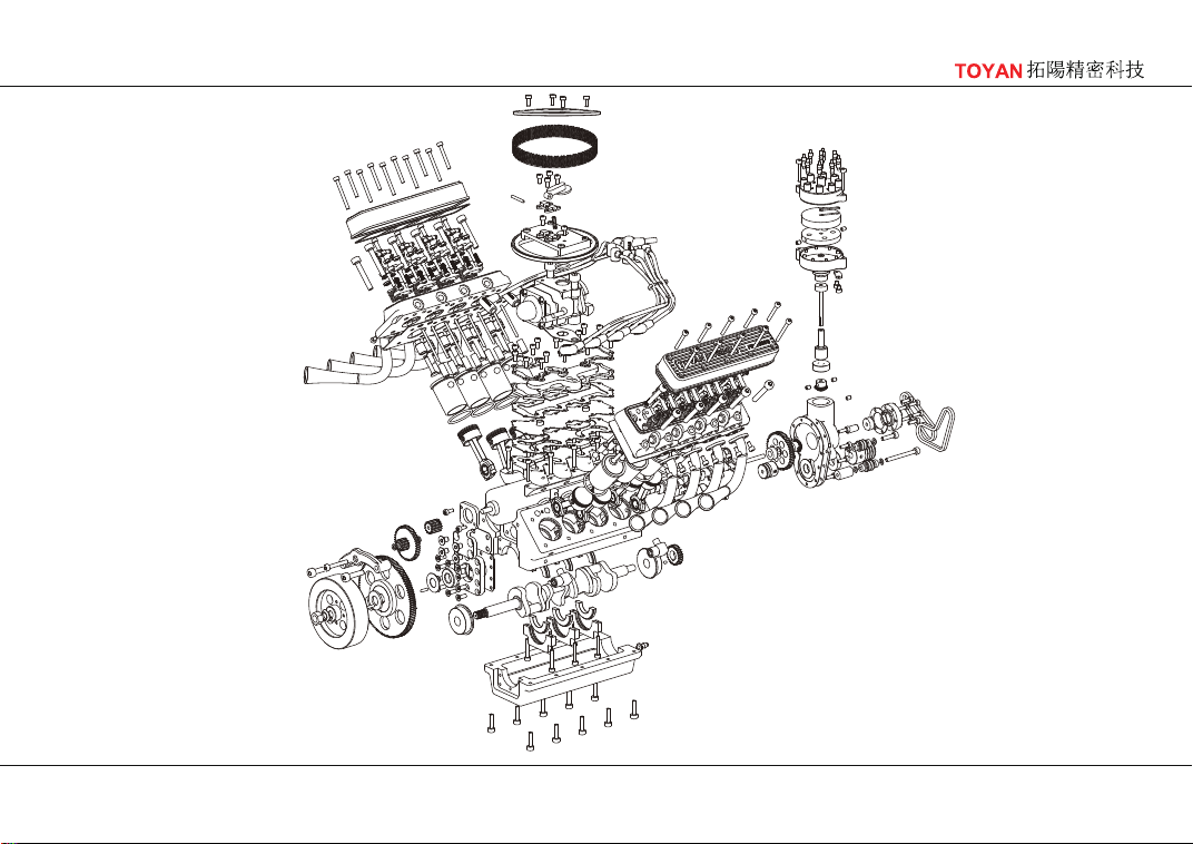
58
Exploded view
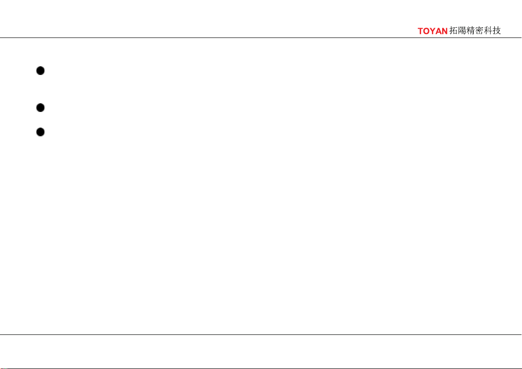
59
Our Commitment
Please contact a TOYAN dealer in your country or location. If you buy through the Internet,
you can also get various parts and complete services through the Internet. Detailed information
about each part can be obtained from the dealer
In the process of use, we have a professional team to answer your technical or usage
questions online for free.
If your distributor is unable to perform its technical services, we will provide you with direct
technical support
60
M6 Nut01
02
03
04
05
06
07
08
09
10
11
12
13
14
15
16
17
18
19
20
21
22
23
24
25
26
27
28
29
30
31
32
33
34
35
36
37
38
39
40
41
42
43
44
45
1 Gear shaft 2 2
Intake rocker arm 8
Exhaust rocker arm 8
Screw M2.5×12 10
Bearing 3*6*2.5 4
Spacer Φ3*5*0.5 6
Screw M4×16 2
Screw M3×30
(Half spiral tooth)
1
Screw M3×20
(Half spiral tooth)
1
Screw M3×12
(Half spiral tooth)
1
Screw M4×20 20
Outer diameter 12x1.5 O ring 1
Outer diameter 10x2 O ring 8
Screw M2.5×16 18
Screw M3×12 10
1
1
Butterfly gasket
Cylindrical pinΦ2×3
1
Cylindrical pinΦ2×8
1
Cylindrical pinΦ2×10
2
Spacer M8*16*0.5
1
Spacer M8*16*1.5
8
Screw M3×4
2
Screw M2.5×6
4
Countersunk M4×6
8
Small Screw head M3×8
8
Rocker arm frame
16
E type circlip 2.5mm
16
M2.5 Nut
16
Rocker arm screw
16
Tappet pin
16
Tappet
1
Nozzle
1
Spacer Φ3*6*0.5
4
Water pipe connector
1
Bearing 3*10*4
1
Bearing 5*10*4
2
Cable buckle
1
Shaft sleeve 3*5*11
2
Screw M5×16
16
Steel ball
18
Screw M2.5×5
2
Gear shaft 1
10
Countersunk M3×8
16
Screw M2.5×10
PART LIST
Name Name Name
61
Exhaust pipe gasket46
47
48
49
50
51
52
53
54
55
56
57
58
59
60
61
62
63
64
65
66
67
68
69
70
71
72
73
74
75
76
77
78
79
80
81
82
83
84
85
86
87
88
89
90
8 Water pump pulley (right) 1 Gear 4 1
Flange bearing 8*22*7 2
Motor bracket 1
Rocker arm seat 8
Intake duct cover 1
Intake duct
metal gasket
1
Oil seal 2
Pulley 2
Intake duct cover
insulation pad
2
Air filter 1
Intake duct 1
Start Motor 1
Distributor housing 1
Short O-ring belt 2
Long O-ring belt 2
Gear 5 1
Shaft sleeve 3*8*13.5 1
Gear 3 1
Gear cover 1
Gear 2 1
Gear 1 1
Flywheel 1
Water pump cover (right) 1
Water pump cover (left) 1
Distributor housing
bracket
1
Crankshaft pulley 1
Cylinder cover plate 1
Distributor housing
cover
1
Gear 6 1
Screw M2.5×8 33
Screw M2.5×20 10
Screw M2.5×25 10
Screw M2.5×10 2
Outer diameter 22x1.5 O ring 1
Cylinder block 1
Bottom of casing 1
Brace 3
Copper collar 6
Carburetor 1
Power distributor 1
Piston connecting
rod component
8
Crankshaft 1
Water pump pulley (left) 1
PART LIST
Name Name Name
62
Cylinder head(right)91
92
93
94
95
1
Cylinder head(left) 1
Camshaft 1
Cylinder head cover 2
Exhaust pipe (right) 4
96
Exhaust pipe (left) 4
97
Piston ring kit 1
98
8.1 aluminium set 1
99
5.1 aluminium set 1
100
Cylinder head
gasket(right)
1
101
Cylinder head
gasket(left)
1
106
Distributor housing
cover gasket
1
107
Motor bracket gasket 1
108
Cylinder gasket 1
109
Distributor housing
gasket
1
110
Water pump
cover gasket
2
111
Cable 1
102
Cylinder head cover
gasket
2
103
Intake duct
gasket 1
1
104
Intake duct
gasket 2
1
105
Carburetor gasket 1
PART LIST
Name Name Name