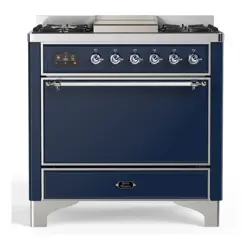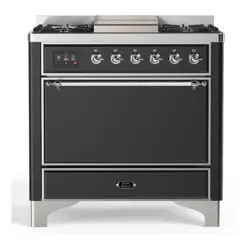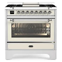

COOKERS
PROFESSIONAL
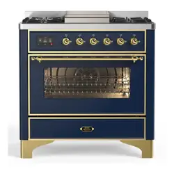
U (P/N) 30
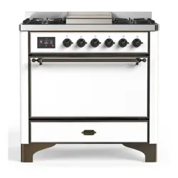
U (P/N) 36
U (P/N) 361
U (P/N) D36
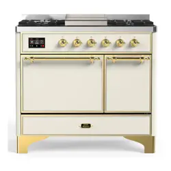
U (P/N) D40
U (P/N) 48
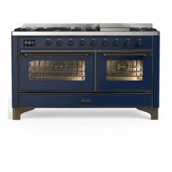
U (P/N) 60
U (P/N) I304
U (P/N) I366
U (P/N) I3616
U (P/N) ID366
U (P/N) DI406
U (P/N) I486
29 7/8” (W) x 25 19/32” (D) x 36 1/2” (H)
35 7/8” (W) x 25 19/32” (D) x 35 55/64”- 36 7/32”] (H)
35 7/8” (W) x 25 19/32” (D) x 35 55/64”- 36 7/32”] (H)
35 7/8” (W) x 25 19/32” (D) x 35 55/64”- 36 7/32”] (H)
39 7/8” (W) x 25 19/32” (D) x 35 55/64”- 36 7/32”] (H)
47 7/8” (W) x 25 19/32” (D) x 35 55/64”- 36 7/32”] (H)
59 7/8” (W) x 25 19/32” (D) x 35 55/64”- 36 7/32”] (H)
29 7/8” (W) x 25 19/32” (D) x 35 55/64” (H)
35 7/8” (W) x 25 19/32” (D) x 35 55/64”- 36 7/32”] (H)
35 7/8” (W) x 25 19/32” (D) x 35 55/64”- 36 7/32”] (H)
35 7/8” (W) x 25 19/32” (D) x 35 55/64”- 36 7/32”] (H)
39 7/8” (W) x 25 19/32” (D) x 35 55/64”- 36 7/32”] (H)
47 7/8” (W) x 25 19/32” (D) x 35 55/64”- 36 7/32”] (H)
EN
User’s manual
Cookers characteristics
These warnings refer to dierent models of cookers.
Be sure that you have correctly identied the model that you possess
(see the rating plate).
2
- Before beginning, please read these instructions
completely and carefully.
- Do not remove permanently axed labels, warnings, or
plates from the product. This may void the warranty.
- Please observe all local and national codes and ordinances.
- Please ensure that this product is properly grounded.
- The installer should leave these instructions with the
consumer who should retain them for local inspector’s use
and for future reference.
WARNING
Tipping hazard
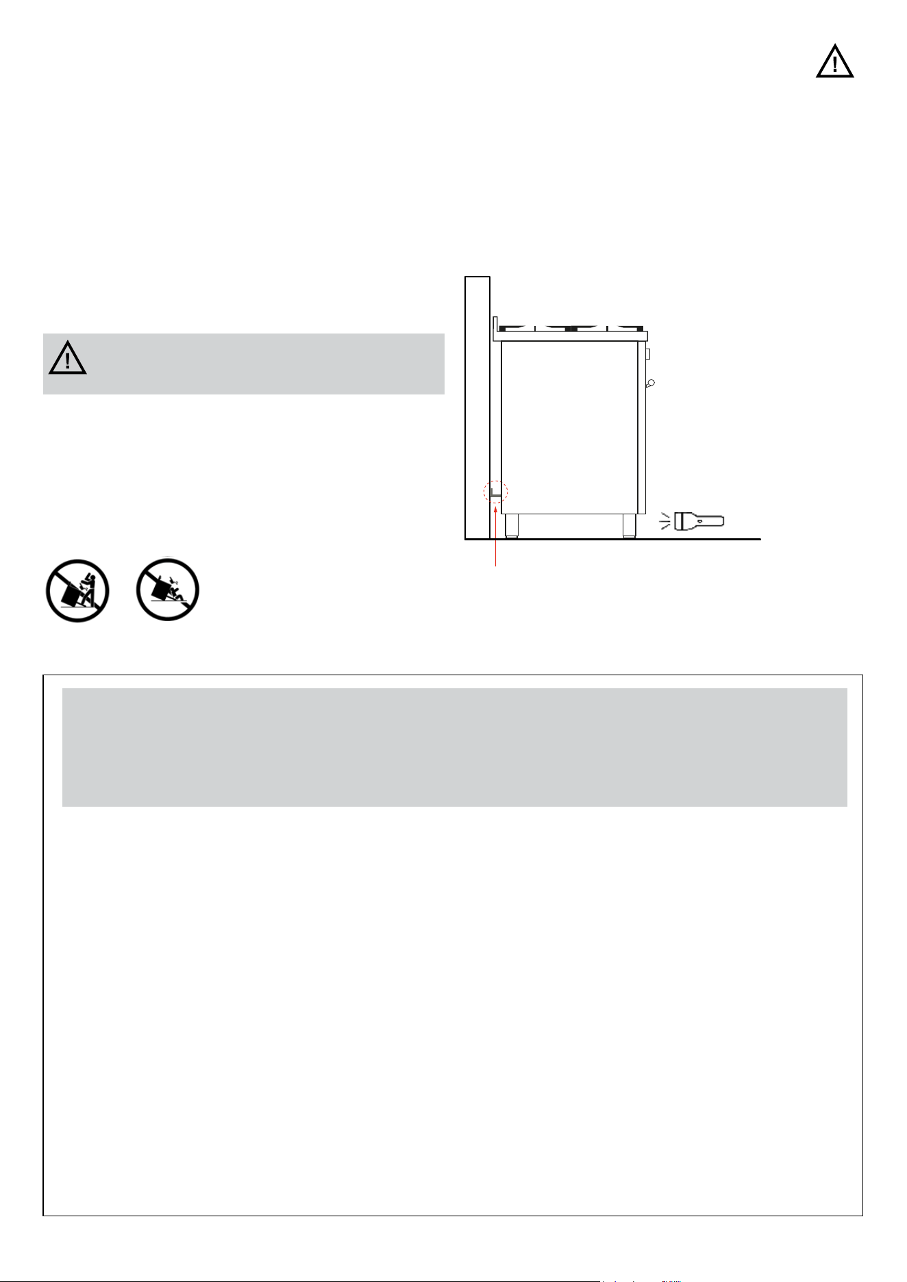
To reduce the risk of the appliance tipping, it must besecured
by a properly installed anti-tip bracket(s). Verify that the anti-
tip bracket has been properly attached to the oor or wall as
directed in the installation instructions. Aer removing the
drawer, or the panel under the door, using a ashlight, verify
that the anti-tip bracket has been installed properly.
- THIS RANGE CAN TIP
- INJURIES TO PERSONS CAN RESULT
- INSTALL ANTI-TIP DEVICE PACKED
- WITH RANGE
- SEE INSTALLATION INSTRUCTIONS
Anti-tip bracket
IMPORTANT - PLEASE READ AND FOLLOW
WARNING If the informations in this instructions is not
followed exactly, a re or explosion may result causing
property damage, personal injury or death.
— Do not store or use gasoline or other ammable vapors and liquids in the
vicinity of this or any other appliance.
— WHAT TO DO IF YOU SMELL GAS:
- Do not try to light any appliance.
- Do not touch any electrical switch.
- Do not use any phone in your building.
- Immediately call your gas supplier from a neighbor’s phone.
- Follow the gas supplier’s instructions.
- If you cannot reach your gas supplier, call the re department.
— Installation and service must be performed by a qualied installer, service
agency or the gas supplier.

3
IMPORTANT - PLEASE READ AND FOLLOW
- NEVER use this appliance as a space heater to heat or
warm the room. Doing so may result in carbon monoxide
poisoning (only for GAS cooking).
- IF YOU OR SOMEONE IN YOUR FAMILY HAS A
PACEMAKER, PLEASE CONSULT WITH A PHYSICIAN
BEFORE USING. Due to high operating frequencies,
a pacemaker may not function properly due to
electromagnetic transmissions.
- Keep appliance area clear and free from combustible
materials, gasoline and other ammable vapors and
liquids.
- A child or adult can tip the range and be killed.
- Install the anti-tip device to the structure and/or the
range. Verify the anti-tip device has been properly
installed and engaged [2 options are available: please
refer to the pictures at page 10].
- Engage the range to the anti-tip device by [2 options
are available: please refer to the pictures at page 10].
Ensure the anti-tip device is re-engaged when the range
is moved.
- Re-engage the anti-tip device if the range is moved. Do
not operate the range without the anti-tip device in place
and engaged.
- See installation instructions for details.
- If the enclosed hardware cannot be utilized, please refer
to a qualied installer to properly fasten the appliance so
that it does not tip over.
- Failure to do so can result in death or serious burns to
children or adults.
- Installation must conform with local codes or in absence
of codes, the National Fuel Gas Code ANSIZ223.1/
NFPA 54 latest edition. Electrical installation must be
in accordance with the National Electrical Code, ANSI/
NFPA70 latest edition and/or local codes. IN CANADA:
Installation must be in accordance with the current CAN/
CGA-B149.1 National Gas.
- Installation Code or CAN/CGA-B 149.2, Propane.
Installation Code and/or local codes. Electrical
installation must be in accordance with the current CSA
C22.1 Canadian Electrical Codes Part 1 and/or local
codes.
- Installation of any gas –red equipment should be made
by a licensed plumber . A manual gas shut-o valve must
be installed in the gas supply line ahead of the oven in the
gas stream for safety and ease of service.
- In Massachusetts: All gas products must be installed by
a “Massachusetts” licensed plumber or gastter . A “T”
handle type manual gas valve must be installed in the gas
supply line to this appliance. The manufacturer will not
be responsible for any damage to property or to persons
caused by incorrect installation or improper use of the
appliance.
- The manufacture reserves the right to make changes
to its products when considered necessary and useful,
without aecting the essential safety and operating
characteristics.
- This appliance has been designed for non-professional,
domestic use only.
- This appliance must be used only for the purposes for
which it was intended. Any other use is incorrect and
therefore dangerous.
- Possible hazards may result from using this appliance for
storage space.
- Appliances are not intended for manufactured (mobile)
home installation .
- Misuse of appliance doors or drawers such as stepping,
leaning or sitting on them can result in damage or
personal hazards or injuries.
- DO NOT TOUCH HEATING ELEMENTS OR INTERIOR
SURFACES OF OVEN – Heating elements may be hot
even though they are dark in color. Interior surfaces of
an oven become hot enough to cause burns. During and
aer use, do not touch, or let clothing or other ammable
materials contact heating elements or interior surfaces
of oven until they have had sucient time to cool. Other
surfaces of the appliance may become hot enough to
cause burns – among these surfaces are (identication of
surfaces – for example, oven vent openings and surfaces
near these openings, oven doors, and windows of oven
doors).
- Care must be taken to prevent aluminum foil and meat
probes from contacting the heater elements.
WARNING
WARNING
Never Operate the Top Surface Cookìng Section of this Appliance Unattended
- Failure to follow this warning statement could result in re, explosion, or burn
hazard thai could cause property damage, persona! injury, or death.
- lf a re should occur, keep away from the ap plìance and immediately call your
re department.
DO NOT ATTEMPT TO EXIT AN OIL / GREASE FIRE WITH WATER.

4
IMPORTANT INSTRUCTION
All Appliances:
CAUTION: Do Not Leave Children Alone - Children should
not be le alone or unattended in area where appliance is in
use. They should never be allowed to sit or stand on any part
of the appliance. Do not store items of interest to children
above or at the back of this appliance, as they could climb on
the appliance to reach items and be injured.
Wear Proper Apparel - Loose-tting or hanging garments
should never be worn while using the appliance.
User Servicing - Do not repair or replace any part of the
appliance unless specically recommended in the manual.
All other servicing should be referred to a qualied technician.
Storage in or on Appliance – Flammable materials should
not be stored in an oven or near surface units.
Do Not Use Water on Grease Fires - Smother re or ame or
use dry chemical or foam type extinguisher .
Use Only Dry Potholders - Moist or damp potholders on hot
surfaces may result in burns from steam. Do not
let potholder touch hot heating elements. Do not use a towel
or other bulky cloth.
When using this appliance, do not touch grates, burner caps,
burner bases or any other parts in proximity to the ame.
These components may be hot enough to cause burns.
Never leave this appliance unattended when in use. Boilovers
and greasy spills may smoke or ignite Do not heat unopened
food containers, such as baby food jars and cans. Pressure
build-up may cause the container to burst and cause injury.
Before performing service, shut o gas by closing the gas
shut-o valve and shut o electricy to this appliance For
safety when cooking, set burner controls so ame does not
extend beyond the bottom of pan.
- Wear proper apparel. Loose-tting or hanging garments
should never be worn while using this appliance.
- Use extreme caution when moving a grease kettle or
disposing of hot grease.
- Clean only those parts listed in this guide.
- Do not repair or replace any part of this appliance unless
specically recommended in literature accompanying
this appliance.
- Do not obstruct the ow of air to ensure proper
combustion and ventilation.
- IMPORTANT: Do not install a ventilation system that
blows air downward toward this gas cooking appliance.
This type of ventilation system may cause ignition and
combustion problems with this gas cooking appliance
resulting in personal injury or unintended operation.
- Proper Installation – Be sure your appliance is properly
installed and grounded by a qualied technician.
- Never Use Your Appliance for Warming or Heating the
Room.
Ovens:
1. Use Care When Opening Door - Let hot air or steam
escape before removing or replacing food.
2. Do Not Unopened Food Containers - Build up of pressure
may cause container to burst and results in injury.
3. Keep Oven Vent Ducts Unobstructed.
4. Placement Of Oven Racks - Always place oven racks
in desired location while oven is cool. If rack must be
moved while oven is hot, do not let potholder contact hot
heating element in oven.
5. Do Not Leave Children Alone – Children should not be
le alone or unattended in area where appliance is in
use. They should never be allowed to sit or stand on any
part of the appliance.
6. Wear Proper Apparel – Loose-tting or hanging garments
should never be worn while using the appliance.
CALIFORNIA PROPOSITION 65
WARNING : this product can expose you to chemicals
including lead and cadmium, which are known to the State
of California to cause cancer and birth defects or other
reproductive harm. For more information go to:
www.P65Warnings.ca.gov
WARNING
This equipment complies with part 18 of the FCC Rules.
Person with a pacemaker or similar medical device should exercise caution when using or standing near an induction unit
while it is in operation. The electromagnetic eld may aect the working of the pacemaker or similar medical device. It is
advisable to consult your doctor or the pacemaker manufacturer about your particular situation.
Supplier’s Declaration of Conformity
47 CFR § 2.1077 Compliance Information
Responsable Party -ILVE USA
2215 EAST 5TH STREET
BROOKLYN, NY 11223
0018008294933
WWW.ILVE.COM
FCC Compliance Statement
This device complies with Part 18 of the FCC Rules

5
- Use Proper Pan Size – This appliance is equipped with
one or more surface units of dierent size. Select utensil
shaving at bottoms large enough to cover the surface
unit heating element. Proper ratio of utensil to cooking
zone will also improve eciency.
- Protective Liners – Do not use aluminum foil to line oven
bottom, installation of these liners may result in a risk of
electric shock, or re.
- Avoid spilling water or other liquids onto the Induction
Cooker, and never immerse the unit in water.
- Do not touch the Ceramic Plate immediately aer
cooking - it may be hot from residual heat from the
utensil.
- Do not place or store very heavy objects on the ceramic
plate.
- The heating area is warmed up from the heat of the pan.
To avoid injuries (burning) do not touch the heating
- area.
- Do not insert any piece of paper, cardboard, cloth, etc.
Between the pan and the heating area, as this might
initiate a re.
- As metallic objects are heated up very quickly when
placed on the operating heating area, do not place
any otherobjects (closed cans, aluminium foil, cutlery,
jewelry, watches etc.) on the induction cooker.
- Aluminium foil and plastic vessels are not to be placed on
the hot surface.
- The surface must not be used for storage.
- Do not place credit cards, phone cards, cassette tapes,
or other objects that are sensitive to magnetism on the
ceran plate.
- Do not use pans with an uneven bottom. This might
cause internal damage.
- If the supply cord is damaged, it must be replaced by the
manufacturer, its service agent or a similarly qualied
person in order to avoid a hazard.
- Do Not Cook on Broken Cook-Top- Il cook-top should
break, deaning sotutioos and spillovers may penetrate
the broken cook-top and aeate a risi< of electric shock.
Cootact a qualied technician immediately.
- Clean cook-top with caution — if a wet sponge or cloth
is used to wipe spills on a hot cooking area, be careful to
avoid steam burn. some cleaners can produce noxious
fumes if applied to a hot surface.
- Do not place metallic objects such as knives, forks,
spoons, and lids on the cooktop surface since they can
get hot
- DO NOT TOUCH SURFACE UNITS OR AREAS NEAR
UNITS – Surface units may be hot even though they
are dark in color. Areas nearsurface units may become
hot enough to cause burns. During and aer use, do
not touch, or let clothing or other ammable materials
contact surface units or areas near units until they have
had sucient time to cool. Among these areas is the
glass surface of the cooktop.
INSTRUCTIONS FOR USE
Induction appliance
6
- This appliance shall only be installed by an authorized
person. This appliance shall be installed in accordance
with the manufactures installation instructions,
IMPORTANT: this appliance must be installed in
accordance with the norms in force of the country
concerned.
- The installation of this appliance must conform to local
codes and ordinances. In the absence of local codes.
- Installations must conforms to American National
Standards, National Fuel Gas Code ANSI Z223.1-
NFPA54.
- If local codes permit, a exible metal appliance
connection with the new AGA or CGA certi ed design,
max. 5 feet (1,5m) long, ½” I.D. recommended for
connecting this cooktop to the gas supply line. Do not
bend or damage the exible connector when moving
the cooktop. The pressure regulator has ½” female pipe
thread. You will need to determine the tting required,
depending on the size of your gas supply line, the exible
metal connector and the shuto valve.
- The appliance , when installed, must be electrically
grounded in accordance with local codes or, in absence
of local codes, with the National Electrical Code, ANSI/
NFPA 70, CSA C22.1-02.
- The appliance and its individual shut o valve must be
disconnected from the gas supply piping system during
any pressure testing of that system at test pressure in
excess of ½psi (3,5kPa).
- The appliance must be isolated from the gas supply
piping system by closing its individual manual shuto
valve during any pressure testing of the gas supply
piping system at test pressure equal to or less than ½psi
(3,5kPa).
- For use with a pressure regulator. The regulator supplied
must be used with this appliance; it shall be properly
installed in order to be accessible when appliance is
installed in denitive position.
- The gas appliance pressure regulator must be set for the
gas with which the appliance is used.
- This appliance can be used with Natural gas and
Propane. It is shipped from the factory adjusted for use
with Natural gas: CONVERSION FIXED ORIFICES ARE
LOCATED IN THE LITERATURE PACK SUPPLIED WITH
THE UNIT.
- Injectors kit for the change of type of gas are contained
inside the package jointly with the hob installation kit
and Instruction booklet. The maximum inlet gas supply
pressure incoming to the gas appliance pressure
regulator is 14” water column (5kPa). The minimum
gas supply pressure for checking the regulator setting
shall be at least 1”w.c.(249Pa) above the inlet speci
ed manifold pressure to the appliance (this operating
pressure is 5”w.c. for Natural Gas and 10”w.c. for
Propane.All opening and holes in the wall and oor,
back and under the appliance shall be sealed before
installation of the appliance.
INSTALLATION INSTRUCTIONS
- ATTENTION: A manual valve shall be installed in an
accessible location in the gas line external to the
appliance for the purpose of turning on or shutting o
gas to the appliance.
- WARNING: Do not use aerosol sprays in the vicinity of
this appliance while it is in operation.
- The appliances should not be installed with a ventilation
system that blows air downward toward the range.
WARNING
Before removing the appliance disconnect the electric
power supply cable and close the relevant shut o valve.
Make sure that the electric power supply cable is not
damaged during cleaning/maintenance operations. When
repositioning the appliance make sure that the anti-tip
device is correctly tted again as before removal.
NOTE 1:possible risks may result from abnormal usage,
including excessive
loading of the oven door.
NOTE 2: reinstall the appliance in accordance with the
manufacturer’s
instructions to avoid the risk of tip-over
WARNING
An air curtain or other overhead range hood, which
operates by blowing a downward airown onto a range,
shall not be used in conjunction whit this gas range.
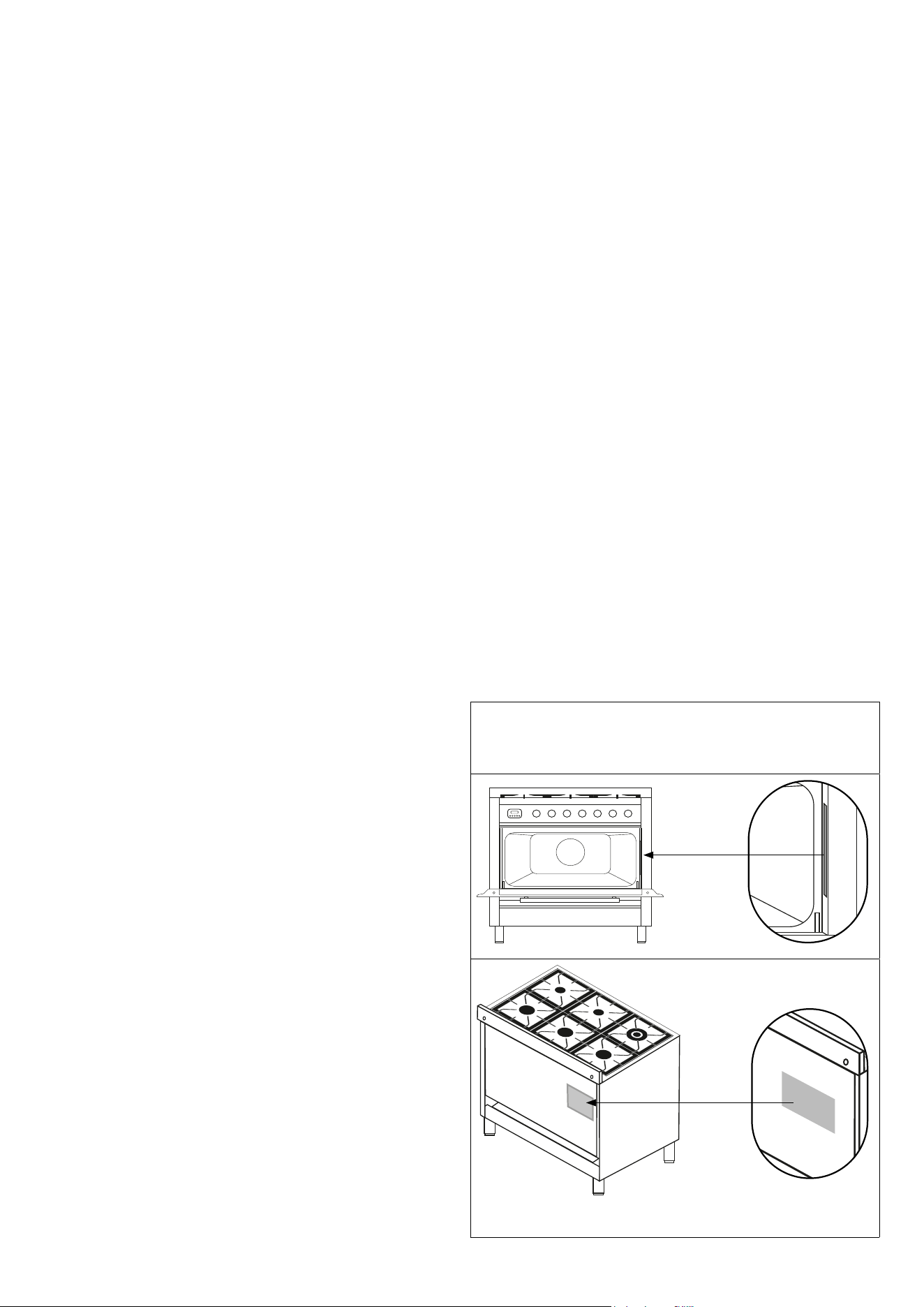
Product Model/Serial Label
and Rating Label Locations
7
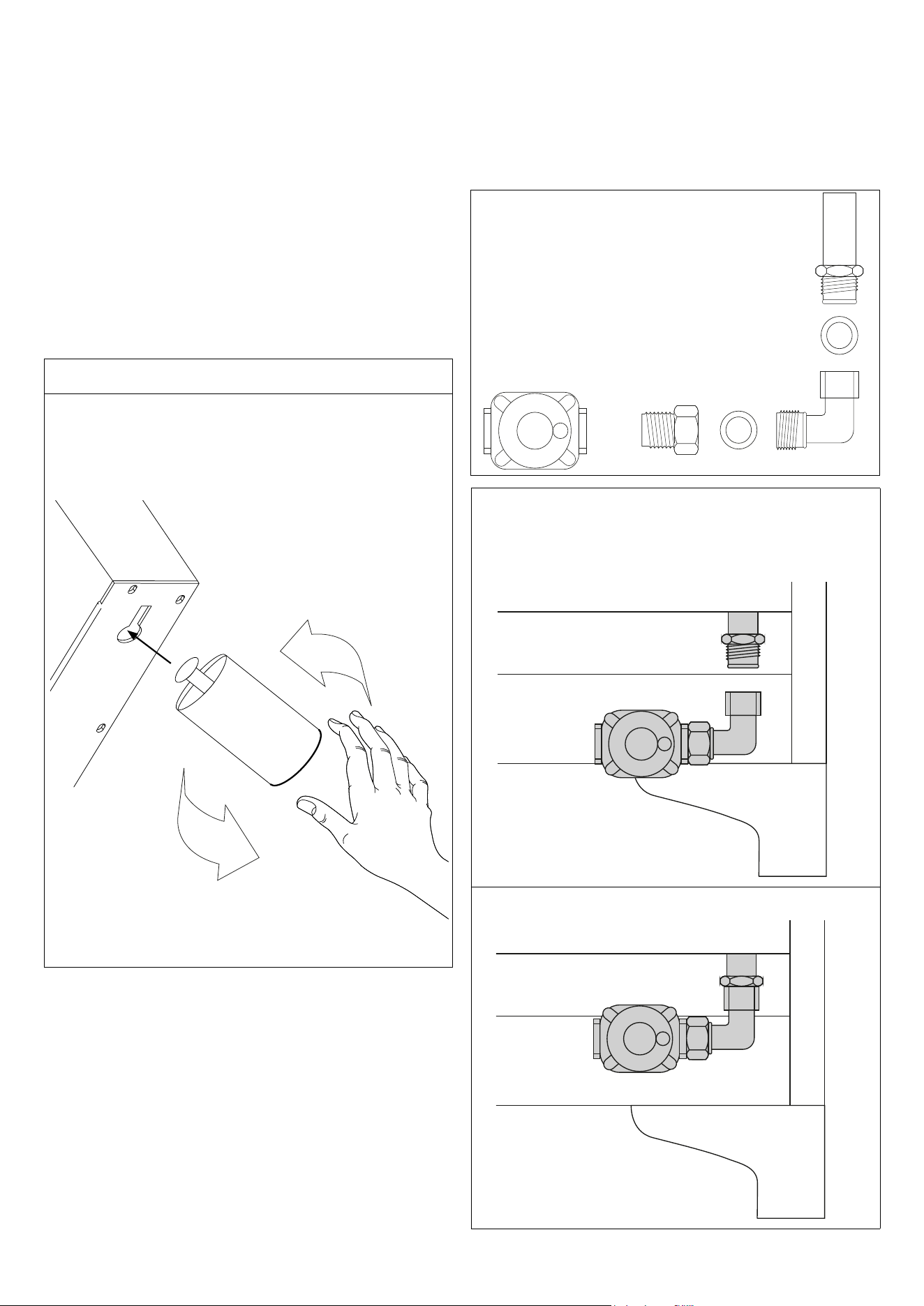
Legs are packed in carton box. Legs should be installed
near to where the appliance is to be used, as they are
not secure for long transit. Aer unpacking the range,
raise it about a foot to remove the bottom shipping skid.
Keep the unit raised to allow legs to be screwed into their
couplings and lower it gently to keep any undue strain from
the legs and internal mounting hardware. It is strongly
recommended that a pallet or li jack be used rather than
tilting.
Professional
1. Screw partially bolt (E) into the base foot (F).
2. Insert base foot (G) into the hole (Ga), move in to the slot
(Gb) and screw completely bolt (E).
F
E
Ga
Gb
INSTALLATION INSTRUCTIONS
Instruction for base feet assembly
PRESSURE GAS REGULATOR
INSTALLATION INSTRUCTION
A
B
E
CE
D
1. Unscrew part “B” from part “C”.
2. Screw part “C” into part “D”. Use a suitable gasket for this
connection.
3. Screw part “D” into part “A”.
A
D
B
C
4. Screw “A”+”D”+”C” part into “B” part.
A
D
B
C
NOTE: Tor connection “B”+”C”+”D” PART USE “E” GASKET
Pressure gas regulator is supplied with the appliance. It is
stored in the oven.
8
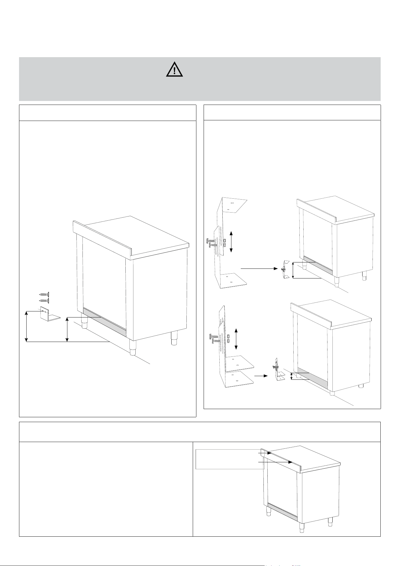
OPTION 1: wall bracket
1. DUnpack the kitchen, mount the feet and adjust the
height.
2. Measure the height from the oor to the top edge of the
rear cross bar and add 15 mm.
3. Mark the total height on the back wall in the center of
the width of the kitchen. Drill two holes and install the
mounting bracket.
4. CAUTION: Make sure the stove is leaning against the
back wall to prevent it from tipping over.
HOW TO INSTALL THE ANTI-TIP BRACKET
OPTION 2: oor mounted bracket
1. ATTENTION: in this case 2 brackets are needed
2. Hook the apparatus onto the anti-tip device as explained
in the picture.
3. Reinsert the anti-tip device if the apparatus is moved.
4. See pictures for details.
5. Failure to follow this procedure may result in death or
serious burns to children or adults..
WARNING
A child or adult may tip over the device and be killedInstall the anti-tip device on the structure and/or polygon
(see pictures for details).
BACKGUARD INSTALLATION INSTRUCTION
Please follow the following installation instructions in
sequence:
- Place the backguard and fasten it with the two screws
as shown in gure.
- Please refer to a qualied installer in case the enclosed
hardware cannot be utilized.
Fix backguard using two
screws
9
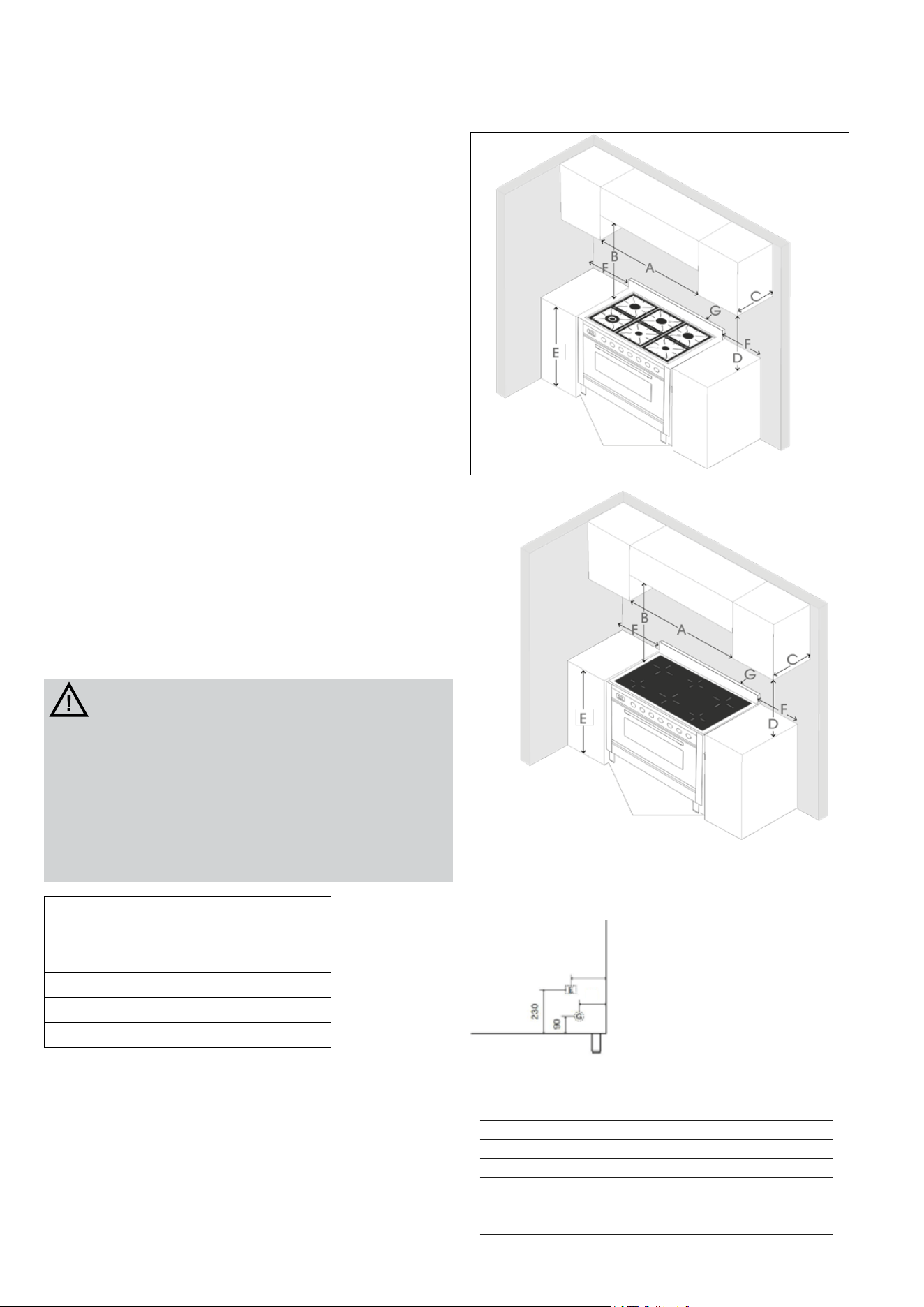
MINIMUM SPACING FROM COMBUSTIBLE CONSTRUCTION
1. This range shall be installed directly adjacent to existing
[33 15/32” - 36 20/32”] high base cabinets.
2. IMPORTANT: The top border of the worktop should be at
the same level of the adjacent cabinets counter top. This
may be accomplished by raising using the adjustment
spindles on the legs.
3. The range CANNOT be installed directly adjacent to
sidewall, as cabinets, appliances, or other side vertical
surface above 36 20/32” high. There must be a minimum
of 5” side clearance.
4. Within the side clearance to combustible vertical surfaces
above 36 20/32”, the maximum wall cabinet depth must be
13” and wall cabinets within this side clearance within this
side clearance must be 18” above the 36” high countertop.
5. Distance A cannot be less than width of the appliance.
6. Distance G this range shall be installed directly adjacent to
back wall ( zero clearance).
7. 36’’ minimum clearance between the top of the cooking
surface and the bottom of an unprotected wood or metal
cabinet (B).
8. Minimum horizontal distance between overhead cabinets
installed to either side of the appliance shall not be less
than the nominal width of the appliance.
9. This appliance is for zero clearance between adjacent
combustible construction below the cooking surface and
back and sides of the appliancde.
CAUTION
Burn hazard
To avoid risk of personal injury; the use of cabinets for storage
above the appliance may result in a potential burn hazard.
Combustible items may ignite, metallic items may become
hot and cause burns. If a cabinet storage is to be provided the
risk can be reduced by installing a range hood that projects
horizontally a minimum 5” (12.7 cm) beyond the bottom of
cabinets. 390mm= 1523⁄64in
A ≥ [35 7/8” – 47 7/8”]
B 36” (91,5cm)
C 13” (33cm)
D 18” (45,7cm)
E 36
1/2
” (92,5cm)
F 5” (12,7cm)
ADJUSTABLE FEET
ADJUSTABLE FEET
Electrical and gas connection
Rear view
Mod. / mm A B
UP30 5
3/64
26
27/64
UP36
7
23/64
6
31/32
4
9/16
UPD36
4
1/16
UP361
7
23/64
6
21/32
UPD40 4
3/8
3
55/64
UP48
5
43/64
5
5/32
7
9/16
UP60
6
27/32
C (230) D (90)
7
3/32
4
49/64
6
47/64
4
13/32
6
47/64
4
13/32
6
47/64
4
13/32
6
47/64
4
13/32
6
47/64
4
13/32
6
47/64
4
13/32
C
D
B
A
Mod. / mm A B
UP30 5
3/64
26
27/64
UP36
7
23/64
6
31/32
4
9/16
UPD36
4
1/16
UP361
7
23/64
6
21/32
UPD40 4
3/8
3
55/64
UP48
5
43/64
5
5/32
7
9/16
UP60
6
27/32
C (230) D (90)
7
3/32
4
49/64
6
47/64
4
13/32
6
47/64
4
13/32
6
47/64
4
13/32
6
47/64
4
13/32
6
47/64
4
13/32
6
47/64
4
13/32
C
D
B
A
10
The appliance shall be connected to a single phase electric line
rated at 120/240Vac and 60Hz frequency.
The appliance is equipped at the factory with a exible hose .
Inside the exible hose you have 4 cables: green cable must
be connected to the ground, white cable (NEUTRAL), red and
black cables: supply wire (F – F1). Check the electrical sketch
available at the end in our instructions booklet.Electric power
absorption values for each model are shown in the Electrical
and Gas Power Table enclosed.
Before connecting the appliance to the electric network, follow
the instructions below:
1. fuse and electric supply installation of your home must
bear the load of the appliance (see registration label).
2. the power supply system must have an ecient earth
connection.
3. the outlet or multiple-switch, with a minimum1/8” (3mm)
contact opening, has to be easily reached once the
appliance has been installed.
Induction appliance
The connection of the electrical supply must be done by
approved installation contractors in accordance with specic
National and Local installation standards in conformity with all
safety regulations. The warning signs and rating plates on the
appliances must strictly be followed.
This unit is manufactured for a polarized, grounded 120/240
volt 60Hz (2 phases 6 AWG, 1 neutral 8 AWG, 1 ground 8 AWG
0with plug).
Check and ensure that the supply voltage and the line current
matches the specications given on the rating plate.
Before connecting the appliance to the electric network, follow
the instructions below:
4. fuse and electric feeding installation of your home must
support the load of the appliance (see registration label);
5. power supply system must be properly grounded;
6. the outlet or multiple-switch, with 1”3/8 inch diameter
connection opening, has to be easily reached once the
appliance has been installed;
7. the power supply cable should not reach a 120°F
temperature.
ELECTRICAL CONNECTION
WARNING
If the voltage is wrong, the cooker can
be damaged.
WARNING
Dangerous electric voltage inside!
DO NOT OPEN induction unit.
CAUTION
Risk of Electric Shock. If the cord or
plug becomes damaged, disconnect
the appliance from the power supply
and replace only with a cord or plug
of the same type
WARNING
Electrical Grounding Instructions
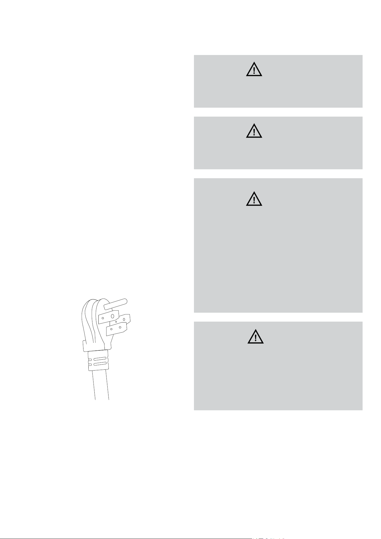
This appliance is equipped with a
(four-prong) grounding plug for your
protection against shock hazard and
should be plugged directly into a
properly grounded receptacle. Do not
cut or remove the grounding prong
from this plug

11
All gas connections must be made according to national and
local codes. This gas supply (service) line must be the same
size or greater than the inlet line of the appliance. This range
uses a ½”NPT inlet. Sealant on all pipe joints must be resistant
to Propane.
1. Manual Shut-o Valve:
- This installer-supplied valve must be installed in the gas
service line ahead of the appliance in the gas stream and
in a position where it can be reached quickly in the event of
an emergency. The manual shut-o valve shall be installed
properly in order to be accessible when appliance is
installed in its nal position. In Massachusetts: A ‘T’ handle
type manual gas valve must be installed in the gas supply
line to this appliance.
2. Pressure Regulator:
- All heavy duty, commercial type cooking equipment must
have a pressure regulator on the incoming service line
for safe and ecient operation, since service pressure
may uctuate with local demand. The pressure regulator
is supplied separately with the appliance; regulator has
two female threads ½” NPT ; it shall be installed properly
in order to be accessible when appliance is installed in its
nal position position.
- This range can be used with Natural or Propane gas. It is
shipped from the factory adjusted for use with natural gas.
The orice hoods must be screwed snug when Propane
gas is used(see Propane conversion).
- The appliance, its individual shut-o valve, and pressure
regulator must be disconnected from the gas supply
piping system during any pressure testing of that system at
pressure in excess of 1/2psig(3.45kPa).
- The appliance must be isolated from the gas supply piping
system by closing its individual manual shut-o valve
during any pressure testing of gas supply piping system at
test pressures equal to or less than 1/2psig(3.45kPa).
3. Flexible Connections:
- If the unit is to be installed with exible couplings and/or
quick disconnect ttings, the installer must use heavy duty,
AGA design-certi +ed commercial exible connector of
at least ½”(1.3cm)ID NPT(with suitable strain relieves) in
compliance with ANSI Z21.41 and Z21.69 standards.
- In Massachusetts: The unit must be installed with a 36” (3-
foot) long exible gas connector.
- In Canada: CAN 1-6.10-88 metal connectors for gas
appliances and CAN 1-6.9M79 quick disconnect device
for use with gas fuel.
CAUTION: Leak testing of the device should be performed
in accordance with the manufacturer’s instructions. Before
turning on the oven, always check for leaks with a soapy
water solution of another acceptable method.
DO NOT USE AN OPEN FLAME TO CHECK FOR LEAKS!
All burners are tested before leaving the factory. There are no
adjustments for the burners if connected according to the
information on the rating plate. Check each burner for proper
operations. Flames should be blue in all settings. If service is
required, contact your dealer for the name of their authorized
service agency. Gas conversions and initial installation are not
responsibility of the manufacturer.
The installer should carry out the following performance
checks. Refer to instructions below.
1. Check surface burner ignition.
2. Check low ame adjustment
3. Check for gas leaks (odors) at all gas connections.
REQUIREMENTS
Room ventilation – Location and venting.
ATTENTION: A exhaust fan may be used with the appliance;
in each case it shall be installed in conformity with the
national standards in force.
ATTENTION: Exhaust hood operation may aect other
vented appliances; in each case it shall be installed in
conformity with the national standards in force.
CONVERSION TO DIFFERENT TYPES OF GAS
Any conversion required must be performed by your dealer
or a qualied licensed plumber or gas service company.
Please provide the service person with this manual before
work is started on the range.(Gas conversions are the
responsibility of the dealer or end user.)
CAUTION
Before proceeding with the conversion, shut o the gas
supply to the appliance prior to disconnecting the electr
ical power.
The appliance is supplied for use with a certain type of
gas; if this has to be varied, you must change the burner
injectors, adjust the minimum gas ow.
Before carrying out these operations you must disconnect
the electric power supply of the cooker to avoid accidental
contacts.
Before carrying out any maintenance work, disconnect the
appliance from the gas and electric supply.
GAS CONNECTION PERFORMANCE CHECKLIST
12
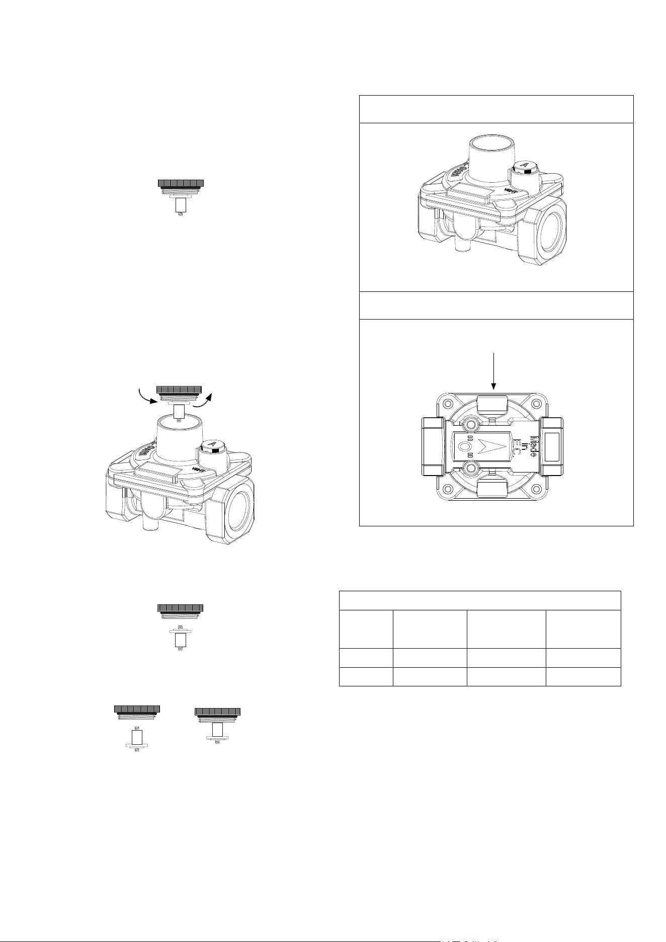
The pressure regulator supplied with the appliance is a
convertible type pressure regulator, suitable for use with
natural gas at a nominal outlet pressure of 5” water column or
with propane at a nominal outlet pressure of 10” water column.
It is factory pre-arranged to operate with natural gas.
If converting from natural gas to propane, it is also necessary to
adjust the bypass orice. The bypass orice adjustment screw
must be fully screwed in.
To convert the regulator for use with the other gas (dierent
from the one for which it is pre-arranged), simply perform the
following steps:
1. Unscrew the upper metal stopper of the regulator.
2. Unscrew by hand the white plastic piece screwed under
the above mentioned metal stopper.
3. For propane screw it back in the opposite direction under
the metal stopper.
4. Screw the metal stopper back into its original position on
the regulator. In this way, the gas regulator is converted for
use with the other gas/pressure.
See the table below for gas supply pressure requirements.
Gas supply specications
Gas type
Manifold
pressure * (WC)
Min. Gas Supply
Pressure (WC)
Max. Imput
Pressure
Natural 5 6 1/2 psi
Propane 10 11 1/2 psi
If the line pressure is in excess of that amount, a step down
regulator will be required.
The appliance must be disconnected from the GAS supply
piping system during any pressure testing of that system.
ADJUSTMENT OF THE PRESSURE REGULATOR FOR USE WITH
DIFFERENT TYPE OF GAS
PRESSURE REGOLATOR
PRESSURE REGOLATOR
Pressure test poit
stopper (1/8“NPT)

13
CHANGING THE INJECTORS
BURNER GAS IMPUT RATE
[Btu/h]
ORIFICE SIZE
(1/100) mm
SIMMER RATE
[Btu/h]
BY-PASS ORIFICE
SIZE (1/100) mm
SR NATURAL (A) 7000 120 1400 Adj.*
R NATURAL (A) 10500 145 2000 Adj.*
DUAL NATURAL (A) 25000 75+220 6000 Adj.*
DUAL
(only AUX)
NATURAL (A) 2800 75 900 Adj.*
P NATURAL (A) 10500 145 3100 Adj.*
CDF NATURAL (A) 5500 110 / /
SR PROPANE (E) 7000 7000 75 32
R PROPANE (E) 10500 10500 90 40
DUAL PROPANE (E) 25000 25000 44+135 27+60
DUAL
(only AUX)
PROPANE (E) 2800 2800 44 27
P PROPANE (E) 10500 10500 92 52
CDF PROPANE (E) 5500 5500 65 /
CAUTION: The gas supply shall be shut o prior to
disconnecting the electrical power, before proceeding with
the conversion. The kit for the gas conversion of the burners
is relevant to the model of the appliance indicated on the label
sti-cking to the rst page of this booklet. The kit contains the
number and type of orices necessary for the conversion, all
the necessary instructions, a label to stick onto the old one to
show the new setting and the label to be completed by the
technician who performs the conversion. The appliance is pre-
adjusted in factory for the gas indicated on the label put on
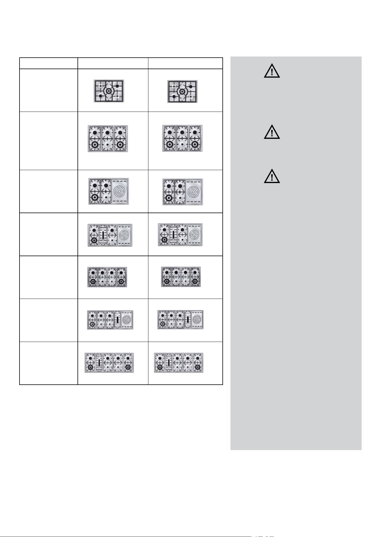
the gas inlet pipe. For the conversion to another gas refer to
table.The positions, types of burner and relevant orices for the
models included in this booklet are depicted in table. The only
operation to perform aer conversion to a gas dierent from
that shown on the rating plate/label is the adjustment of the
minimum gas ow. Aer conversion remember to put the new
gas indication label (supplied in the conversion kit) as close
as possible to the existing rating plate, then check the regular
ignition of the burners.
If the appliance is installed at an altitude exceeding 2,000 ,
a new set of orices can be requested from the supplier or an
authorised service parts distributor.
NOTE: Due to the lower atmospheric pressure at higher
altitudes, foods tend to take longer to cook. Therefore, recipe
adjustments should be made in some cases. In general, no
recipe adjustment is necessary for yeast-risen baked goods,
although allowing the dough or batter to rise twice before
the nal pan rising develops a better avor. Try making the
adjustments below for successful recipes. Take note of the
changes that work best and mark your recipesaccordingly.
You may also consult a cookbook on highaltitude cooking for
specic recommendations.
WARNING: aer rst installation of the appliance, aer gas
conversion kit installation or aer any service intervention
concerning main gas parts of the appliance, make the leak test
using water with soap on the gas connections in order to verify
the correct installation. Do not use re for gas leak testing.
The test is valid if there is no bubble or foam build-up during a
period of one minute.
14
CONVERSION KIT INSTALLATION INSTRUCTIONS
WARNING
Save the orices removed
from the appliance for future
use
WARNING
To go back to the original set
replace old orices as shown
WARNING
This conversion kit shall
be installed by a qualied
service agency in accordance
with the manufacturer’s
instructions and all applicable
codes and requirements
of the authority having
jurisdiction. If the information
in these instructions is
not followed exactly, a re,
explosion or production of
carbon monoxide may result
causing property damage,
personal injury or loss of life.
The qualied service agency
is responsible for the proper
installation of this kit. The
installation is not proper and
complete until the operation
of the converted appliance is
checked as specied in the
manufacturer’s instructions
supplied with the kit.
CCOODDEE NNAATTUURRAALL GGAASS PPRROOPPAANNEE GGAASS
UUPP3300((WW//NN//QQ))((MMPP//SS33))
UUNN3300((WW//QQ//NN//QQNN))((MMPP//
SS33)) UUTT3300((WW))((SS33))
UUPP3366((66//FF))((WW//NN//QQ))((MMPP//SS33))
UUNN3366((66//FF))((WW//QQ//NN//QQNN))((MMPP//
SS33)) UUTT3366((66//FF))((WW))((SS33))
UUPP336611((66//FF))((WW//NN//QQ))((MMPP//SS33))
UUNN336611((66//FF))((WW//QQ//NN//QQNN))((MMPP//
SS33)) UUTT
336611((66//FF))((WW))((SS33))
UUPPDD3366((66//FF))((WW//NN//QQ))((MMPP//SS33))
UUNNDD3366((66//FF))((WW//QQ//NN//QQNN))((MMPP//
SS33)) UUTTDD3366((66//FF))((WW))((SS33))
UUPPDD4400((66//FF))((WW//NN//QQ))((MMPP//SS33))
UUNNDD4400((66//FF))((WW//QQ//NN//QQNN))((MMPP//
SS33)) UUTTDD4400((66//FF))((WW))((SS33))
UUPPDD4400((SS))((WW//NN//QQ))((MMPP//SS33))
UUNNDD4400((SS))((WW//QQ//NN//QQNN))((MMPP//
SS33)) UUTTDD4400((SS))((WW))((SS33))
UUPP4488((SS))((WW//NN//QQ))((MMPP//SS33))
UUNN4488((SS))((WW//QQ//NN//QQNN))((MMPP//
SS33)) UUTT4488((SS))((WW))((SS33))
UUPP4488((88//FF))((WW//NN//QQ))((MMPP//SS33))
UUNN4488((88//FF))((WW//QQ//NN//QQNN))((MMPP//
SS33)) UUTT4488((88//FF))((WW))((SS33))
UUPP6600((SS//FFSS))((WW//NN//QQ))((MMPP//SS33))
UUNN6600((SS//FFSS))((WW//QQ//NN//QQNN))((MMPP//
SS33))
UUTT6600((SS//FFSS))((WW))((SS33))
UUPP6600((99//FF))((WW//NN//QQ))((MMPP//SS33))
UUNN6600((99//FF))((WW//QQ//NN//QQNN))((MMPP//
SS33)) UUTT6600((99//FF))((WW))((SS33))
120
75
145
145 145 90 90
90
220+75
135+44
220+75
135+44
145
145 110
90 90
65
135+44 75
220+75 120
145
145
120
220+75 120
75
75
90
90 135+44
145
145
110
120
145
220+75
90
90
65
75
92
135+44
145 145 145 145
90
90
9090
220+75 120 120 220+75
135+44 75 75 135+44
145 145 145 145
110
220+75 120 120
90 90 90 92
65
135+44 75 75
145 145 145 145
120 120 220+75
220+75
90
909092
75 75 135+44
135+44
145
90
15
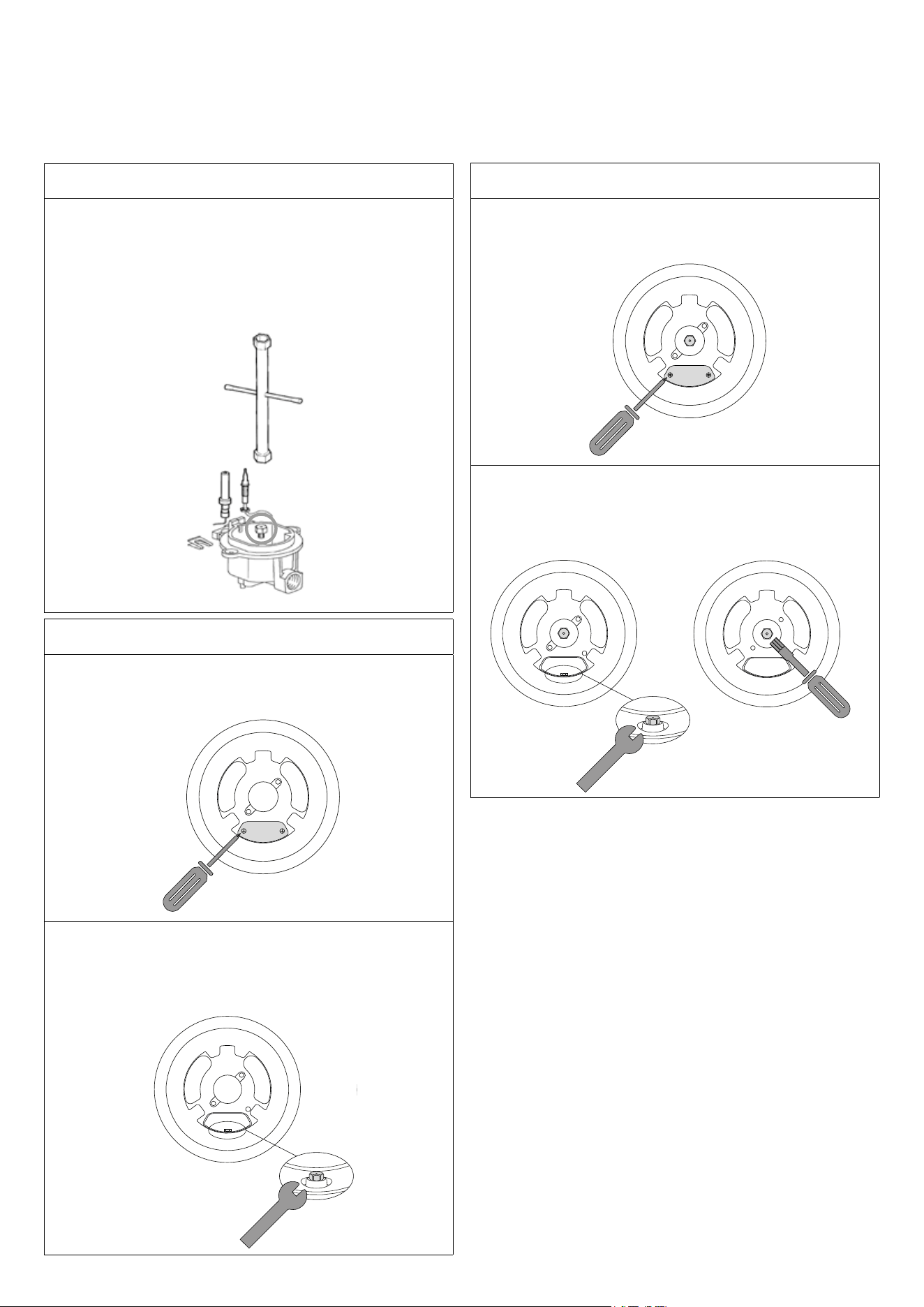
Replacement of the injectors
Procedure: SR - R - P - small solid top burner
1. Remove the grill and the burners from the hob.
2. Bruciatori SR – R – P :
SR – R – P burners: unscrew injectors “U” using a 7-mm
spanner and replace them with those for the newgas
according to table on page 15.
U
Procedure: DCC
1. Remove the grill and the burners from the hob.
2. DCC - Dual burners: unscrew the 2 screws and remove
cover
3. Unscrew the injectors with a 7 mm wrench and replace
them with those for the new gas according to the table
on page 15. Keep the removed injectors from the unit for
future use.
BURNERS OF THE TOP
Procedure: DCC
1. Remove the grill and the burners from the hob.
2. Unscrew the 2 screws and remove cover
3. Unscrew the injectors with a 7 mm wrench and replace
them with those for the new gas according to the table
on page 15. Keep the removed injectors from the unit for
future use.
16
BURNERS OF THE TOP SERVICE & MAINTENANCE
INSTRUCTIONS
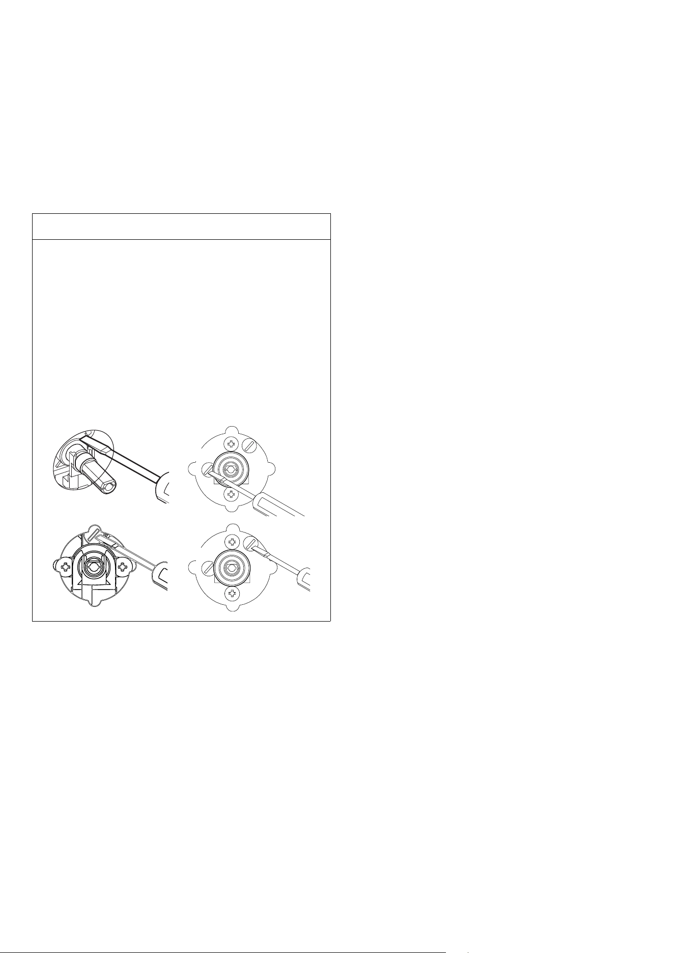
Adjustments minimun GAS flow
Adjustments
When installing the cooker, you must check that the minimum
gas ow of the burners on the hob and in the oven is correctly
regulated. If the type of gas is changed it is indispensable to
adjust the minimum ow. The regulating procedure is as
follows.
Procedure
1. Light one burner at a time and turn the ame up
tomaximum.
2. Remove the knob of the corresponding gas tap andinsert
a screwdriver in the end part of the tap or in thescrew.
3. Turn the tap to minimum position.
4. Unscrew, turning to the le, to increase the ame,
orscrew to the right to decrease it.
5. ATTENTION If a liquid gas is used (Butane - Propane),
theregulating screw must be fully screwed in.
By-pass
regulating
Figure 14b (DUAL)
AUX
AUX
Figure 13 Figure 14a
DUALSR - R - P - DCC
AUX
AUX
Replacement Parts.
Authorized replacement parts may be used in performing
service on the appliance. Replacement parts are available from
factory authorized part distributors.
Service and maintenance only to be carried out by an
authorised person.
To replace parts such burners, valves and electric components,
the hotplate must be removed from the bench top by releasing
the attachment hooks, loosening the attachment screws of
each burner, unscrewing the hotplate attachments nuts which
are visible at the bottom of the surface, removing the hotplate
top and nally replacing the defective parts.
Note 1: if the valves must be replaced, rst disassemble the
ignitions switches wires.
It is recommended to replace the valve gaskets each time the
valve is replaced.
Note 2: if the main gas pipe needs replacement, make sure it
has the correct welded metal supports for assembly.
WARNING: aer rst installation of the appliance, aer gas
conversion kit installation or aer any service intervention
concerning main gas parts of the appliance , make the leak test
using water with soap on the gas connections in order to verify
the correct installation. Do not use re for gas leak testing.
The test is valid if there is no bubble or foam build-up during a
period of one minute.
NON WORKING APPLIANCES
Before calling the Aer Sales Service, check that the appliance
is connected or that the main switch is activated.
Aer, call the Aer Sales Service. The faults must be checked
by an experienced technician.
Remark: the appliance is equipped with a safety thermostat,
adjusted at a certain temperature. In case it reaches a higher
temperature, the appliance switches o
17
CLEANING AND MAINTENANCE
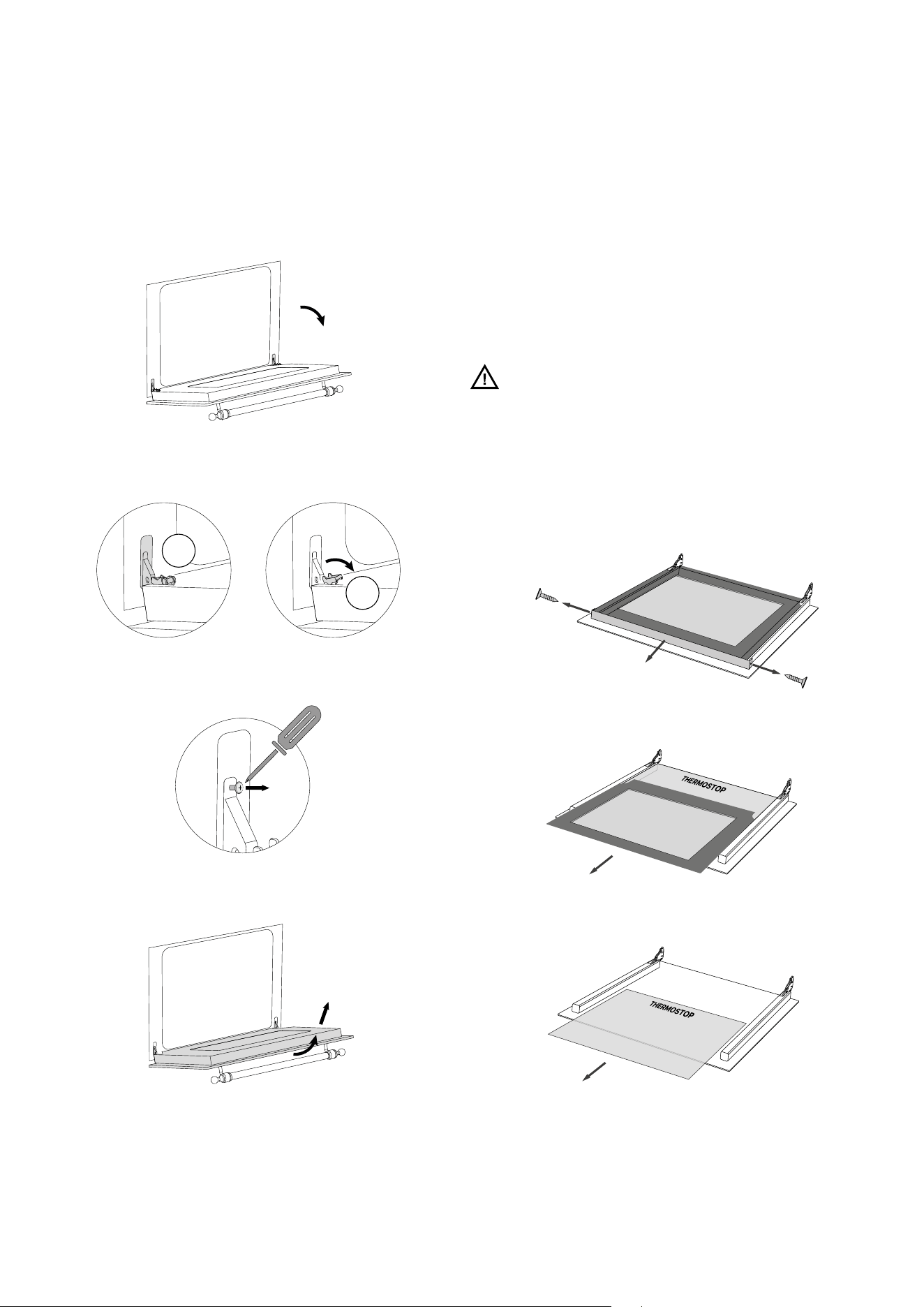
Removing the door
To facilitate intensive cleaning of the oven, it is practical to
remove the door by following these instructions:
1. Open the door:
2. Move the latch C to the hinge section D following the steps:
C
D
- Only on UM30:
3. Remove the door:
Disassembly and cleaning of the glass
The oven door is made up of three glass panels. The cleaning
of the glass parts is done using non-abrasive kitchen paper
and a common detergent. Do not use rough abrasive materials
or sharp metal scrapers to clean the oven glass doors as they
may scratch the surface and cause the glass to break. The
inner glass panels are removable (the middle glass should be
correctly repositioned with the THERMOSTOP writing readable,
as shown in gure 3) to make cleaning easier. To do this, it is
necessary to disassemble the oven door.
ATTENTION: Any operation should always be carried out with
the door removed from the oven and placed on a suitable
surface to avoid damaging the front of the door. The middle
glass must be correctly inserted with the THERMOSTOP label
readable, as shown in the following images:
1. Unscrew the 2 screws on the right/l
eft side of the top strip
2. Li the top glass and slide it out
3. Slide out the middle glass
18
CLEANING AND MAINTENANCE
Procedure
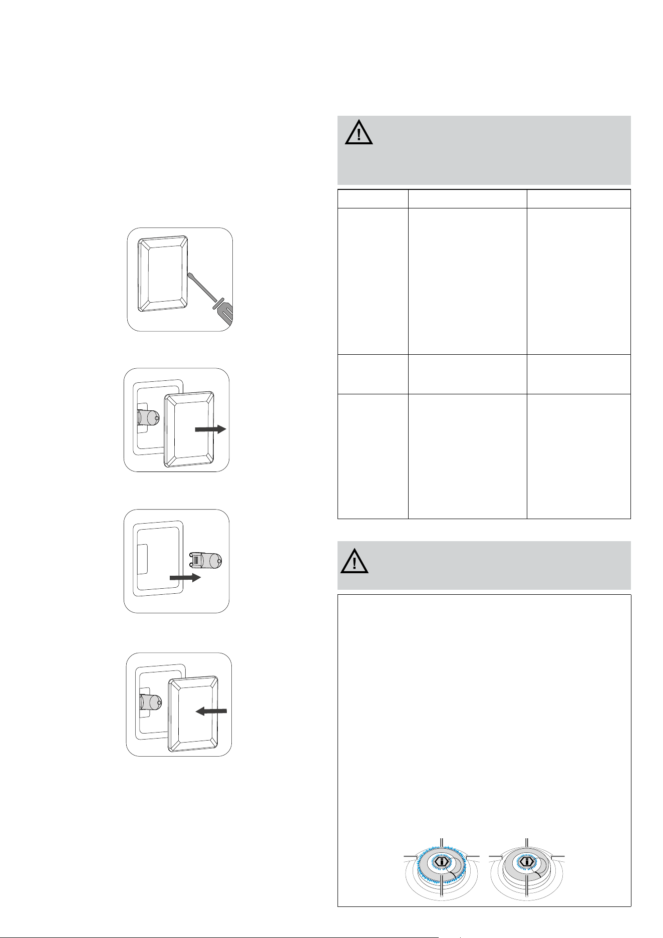
If the oven light is not working, disconnect the appliance from
the power supply, remove the protective glass of the lamp, and
replace the bulb. It is important to ensure that the replacement
bulb is suitable for high-temperature use and has the necessary
specications for such an application.
1. Loosen with a athead screwdriver:
2. Remove the lamp cover glass:
3. Remove the lamp:
4. Replace and close it:
Cleaning the oven
ATTENTION! Before carrying out any cleaning
operations, disconnect the appliance from the mains and
close the gas valve. The cooktop must be cleaned aer it
has been let cooling down.
COMPONENT CLEANING METHOD WARNINGS
Oven inside
It is recommended to clean
the oven aer every use.
Dirt is cleaned more easily
avoiding to let it burn several
times at high temperatures.
Remove every removable
part and clean it separately
with hot water and non-
abrasive detergent. The
cavity is cleaned with a so
cloth soaked with a solution
made of water and ammonia.
Rinse and dry.
Do not use vapor cleaner
to clean the interior of
the oven. Do not use
abrasive/corrosive
detergents or sharp
tools to clean the glass
of the door as they could
damage and break the
surface.
Tray
Immerse in a solution made
of water and neutral soap.
Dry aerwards.
Remove residual food
immediately aer use.
Grills N-acidic detergent.
Acidic substances such
as lemon juice or other
acidic detergents may
permanently damage
the enamel of the grills.
Carefully dry the grills
with a cloth right aer
the cleansing. It is not
recommended to wash
them in the washing
machine.
Cleaning the burners
ATTENTION! Some cleaning and washing methods are
recommended in order to preserve the quality of the coating.
- Allow the product to cool down at room temperature before cleaning it.
It is recommended not to dip it in cold water when it is still hot.
- Wash with warm water and a minimum of neutral detergent. Rub with a
cloth, better if in natural cellulose, or non-abrasive sponge.
- Do not use dust, iron wool, cloths and abrasive sponges.
- Do not let food be charred on the burner. In case stains/colorations may
appear on the surface. These traces do not alter the functionality of
the product, and in some cases can be eliminated with this procedure:
immerse the product in hot water, with detergent, wipe gently with
a cloth, better if in natural cellulose; in any case, do not use abrasive
cloths or sponges. For the most resistant stains, it is advisable to warm
white vinegar and rub as indicated above.
- Avoid leaving the burners in contact with food for a long time, especially
if acidic, such as tomato sauce.
- Avoid contact with metal objects; if really needed, use wooden or
plastic objects.
- Avoid washing in the dishwasher, a part of the product is not coated and
would get irreparably damaged.
- In case of malfunction, make sure that the holes in the outer crown are
perfectly clean.
- For proper operation of the DUAL burner, keep the inter-ignition
channel highlighted in the image below clean.
19
Telescopic guides
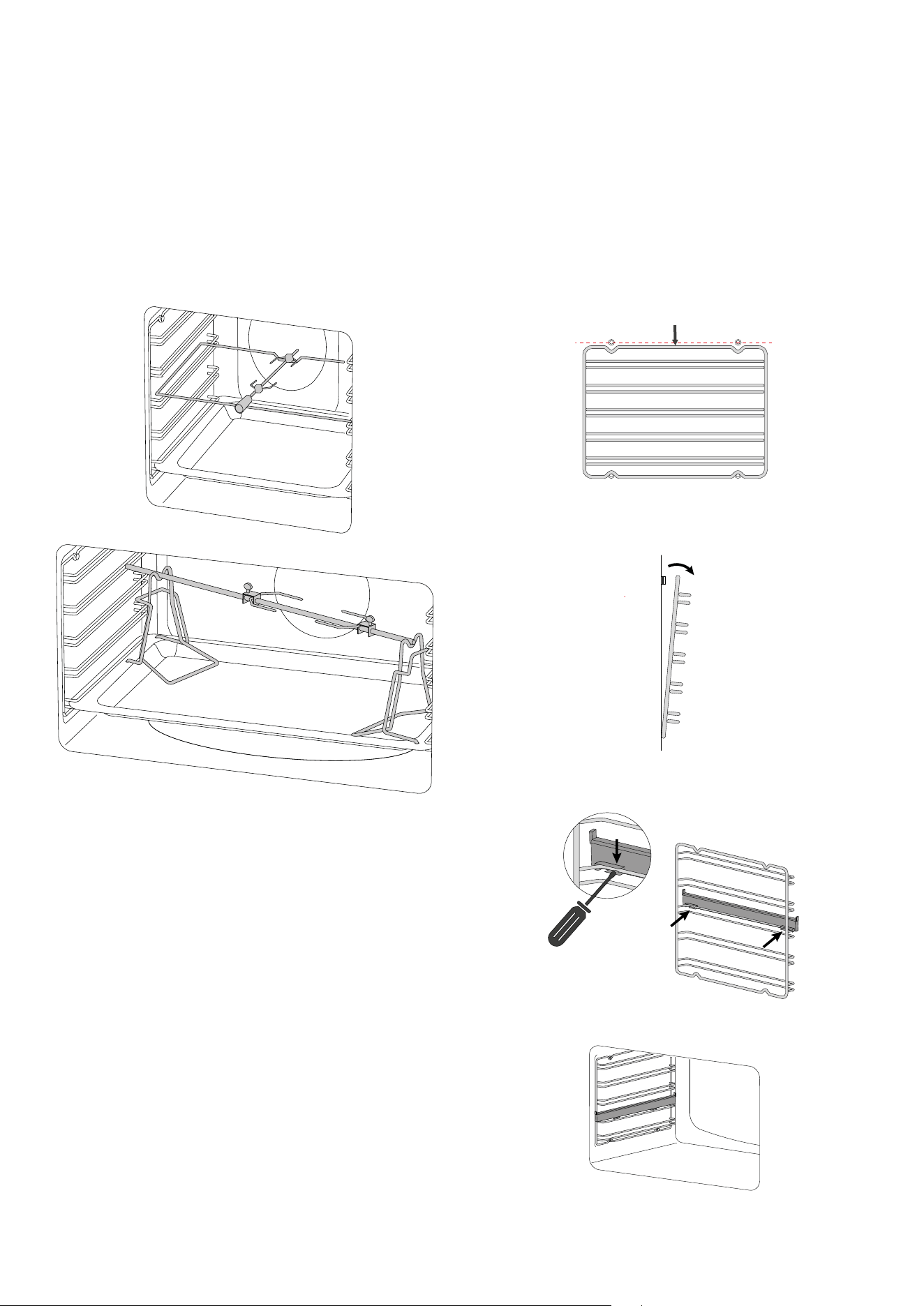
(available only in some models)
This solution is designed to enhance ergonomics, practicality,
and safety when handling trays and pans in the oven. The kit
consists of fully extendable side rails that slide on ball bearings
to facilitate the removal and placement of trays. The rails are
anti-tip for added safety. They can be removed for cleaning or
repositioned, as shown in the photos below.
Pull down the part highlighted in red to remove it from the
oven wall..
Turn them over and place them on a at surface with the
sliding guide side facing down..
To release the clip, loosen it with a athead screwdriver..
Repeat the steps in reverse to reposition the guide..
INSTRUCTIONS FOR USE
Accessories
Use of the rotisserie spit (available only in
some models)
Slide the meat onto the spit rod, securing it with the appropriate
forks. Place the rod onto the rotisserie supports previously
inserted into the drip tray, and insert it into the rotisserie motor
sha. Turn on the static grill function with the door closed. To
remove the spit along with the drip tray, pull it out just enough to
allow for complete extraction.
20
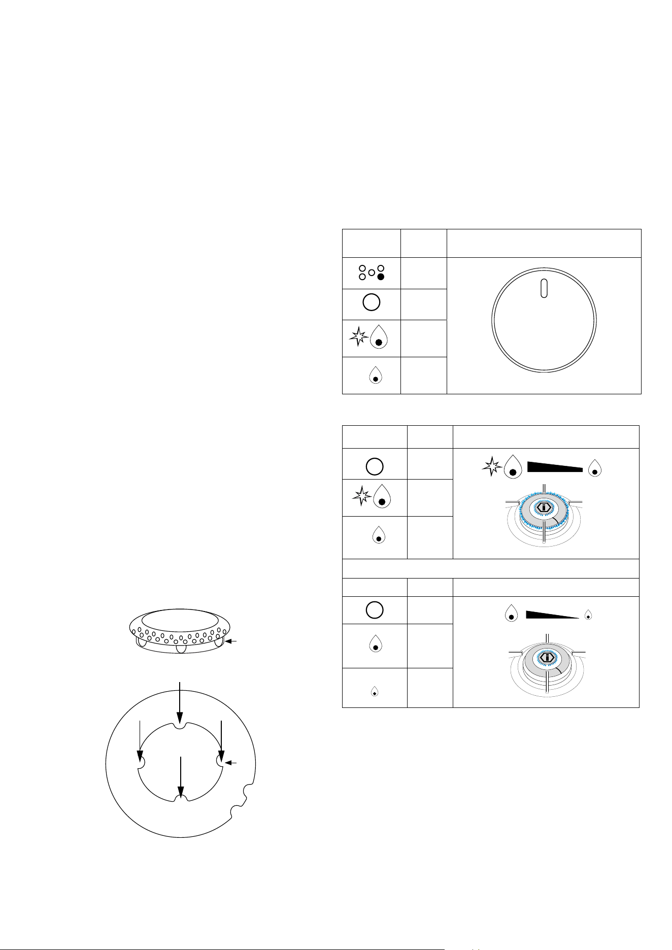
Lighting the burners
The index above the knobs will help you to find the corresponding
burner. Press the knob by turning it anti- clockwise and bring
it to the ignition position; keep the knob pressed for about 5
seconds so that upon its release the flame remains alight. In
case of unsuccessful ignition wait 5 minutes before relighting
and repeat the operation. By turning the knob, the outer
ring lights up red to indicate the GAS burner in operation
Symbol Function Knob
index
o
OFF
max
OFF
min
DUAL
Symbol Function
Knob
o
OFF
OFF
max
OFF
min
AUX
Symbol Function Knob
o
OFF
OFF
max
OFF
min
IGNITION OF THE “DUAL” BURNER
Identify the knob with the help of the index near the knobs. Press
and turn the knob to the symbol (maximum) for 5 seconds.
Once the burner is on, by turning the knob coun-terclockwise
it gets to its first block that corresponds to the middle one By
applying a bit of force, the first block is exceeded and the outer
ring goes out leaving only the little central burner turned on
called AUXILIARY. To adjust the auxiliary burner on minimum,
rotate the knob counterclockwise until it stops. At this point, to
turn the burner back on, rotate the knob clockwise up to the
desired value.
INSTRUCTIONS FOR USE
Burners
IMPORTANT: keep children away from the appliance when
it operates. The oven door becomes very hot. Safety rules do
not always cover any type of accident. The appliance must not
be used for heating purposes. If other electric appliances are
connected to outlets placed near the appliance, make sure that
the connection cables will not be trapped in the oven door while
operating.
GENERAL NOTES: for safety reasons and to ensure proper
functioning of the appliance, any required maintenance
must be undertaken by skilled technicians or aer sales service
in warranty period. Clean the oven regularly aer the use. The
dirt can be easily removed, in this way it will not burn at high
temperatures. Choose heat-resisting pans
according to the quantity of food you want to cook. Stainless
steel containers are not recommended as they re ect
heat. Shelf height should be adjusted as necessary according
to the food to be cooked and the recipe.
FIRST SYSTEM STARTUP: all removable parts of the oven,
should be washed with detergent and then reassembled.
Start the oven for about 60 minutes and set the thermostat to
440°F. During this initial heating period some unpleasant
smell will be experienced, which is unavoidable and quite
normal. When the oven has completely cooled down, clean it
referring to the paragraph «Cleaning and care».
IMPORTANT: be sure that you have correctly identied the
model that you possess (see the data plate).The various
operations are described below, one aer the other. Not all
concern the cooker you have bought, select the ones
that do.
Position the ame divider “B” correctly. To do this, align the
4 teeth “C” of the ame divider with the recess “D” of the
aluminium Cup “A”.
A
B
C
D
IMPORTANT: when you are using the oven for the fi rst time,
let it work empty for one hour, leaving possibly the windows
of the kitchen open. The oven will emanate bad smells due to
production residuals such as greases, oils or resins. Aer that
the oven is ready for the first cooking.
21
INSTRUCTIONS FOR USE
Burners
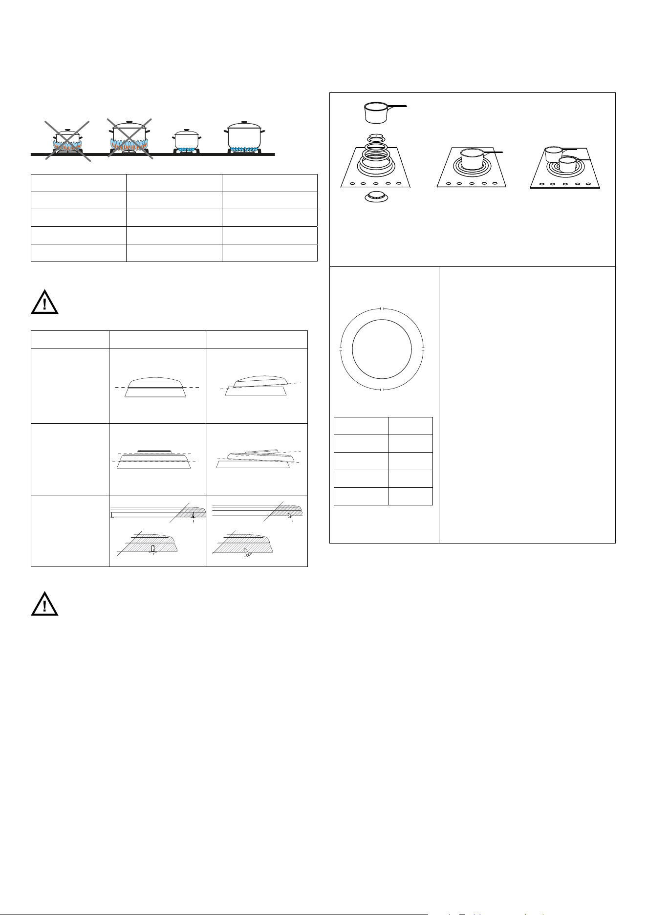
Recommended pans according to burner size:
Burners ID Diameter Ø
Meduim SR 4
3/4
÷ 7
3/4
Large R 4
3/4
÷ 9
2</4
Fish burner P oval pans 380 x 185
Dual - Ring DUAL 4
3/4
÷11
3/4
Positioning of the burners
Always check that the burners are properly positioned), with
a uniform ame that is not noisy.
Burners Right Wrong
Medium
Large
Dual Ring
Fish burner
Always check that
the screws below
the burner are
xed
WARNING
Burners should be operated only when covered by cookware.
Burner flames not covered by cookware present a risk of
fire or clothing ignition. Never let flames extend beyond the
sides of the cookware. Failure to comply may result in serious
injury. Make sure all burners are in their correct locations and
fullly assembled before attempting to operate any burner
Use of the coup feu
The “Coup feu” solid cast iron plate made of concentric rings allows you to
rest the pan (or even several pans) directly on the surface.
It is heated by means of a gas burner.
The plate is designed to provide a moderately intense heat which is well
distributed over the surface.
O
F
F
1
2
•
1
0
•
8
•
•
•
4
•
•
1
3
7
5
°
F
5
2
0
°
F
5
6
5
°
F
6
0
0
°
F
SETTING °F
1 ÷ 4 375 °F
4 ÷ 8 520 °F
8 ÷ 10 565°F
10 ÷ 12 600 °F
To use the appliance, light the ame below
the plate by means of the corresponding
knob and ensure that there is a ame.
This is ideal for slow cooking and particularly
for sauces, browning and grilling, heating
dishes or keeping them warm.
Switch the burner on 15/20 minutes before
use to allow the cast iron plate to accumulate
heat.You will then be able to use the plate
even when switched o for a further 10/15
minutes. The middle of the plate is the area
where the highest temperatures are reached
whereas the outer part is cooler.
By simply moving the pan from the middle
to the outside of the plate, you can obtain
dierent cooking intensities without regulat-
ing the ame. Pan dimensions permitting,
several dishes can be cooked at the same
time . If necessary it can be used as a handy
top, providing ample space for resting pots
and pans.
When the center surface of the plate reaches
the temperature set with the control knob,
the burner ame begins to cycle on and o to
maintain a stable temperature.
Cleaning the Coup feu plate
The hotplate should be cleaned while still warm using the
products normally used in the kitchen for metal surfaces.
Rub with a wire pad, following the direction of the satin finish.
Dry well immediately. If you want to give the plate a better
appearance, after cleaning, apply a coat of a specialist cleaning
paste / cream.
If you do not intend to use the hotplate for long periods, after
normal cleaning apply a thin film of liquid paraffin (Vaseline oil)
with a wad of cotton wool This treatment is
necessary to prevent any formation of surface oxides.
When next turning on the plate you will notice the evaporation
of the paraffin oil used. This phenomenon will disappear in a
few seconds.
The hotplate may sometimes present phenomena of surface
oxidation due to the presence of humidity, but above all due
to lack of use. You are therefore advised to use it frequently to
prevent any oxidation. Never leave the hotplate damp. If the
oxidation phenomenon still appears, use lightly abrasive paper
to remove the oxidation, taking care to rub gently, always in the
direction of the plate satin finish.
Do not cook food directly on the plate surface. Always use
suitable containers.
22
INSTRUCTIONS FOR USE
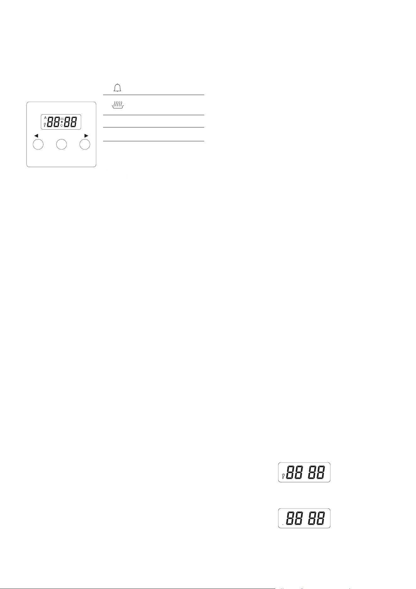
Use of the electronic programmer
Display
Symbols relative to the functions in progress:
MENU
1 32
A
A
[–]/[+]
Timer
A
[–]/[+]
Duration and manual
function
A
Automatic cooking icon
•
Dot icon
MENU
(1) Functio selection
button
A
[–]/[+]
A
[–]/[+]
2 - 3
Press button “3” to
increase and button “2”
decrease
SETTING THE TIME (12-HOUR CLOCK AM/PM)
Aer connecting the appliance or aer a power outage, “0.00”
and “A” will ash on the display.
- Press button 1 for 2 seconds: the dot icon starts ashing.
Set the current time using buttons 2 and 3. Seven seconds
aer nishing the adjustment, the new data will be saved.
- Time correction can be carried out later:
Press buttons 2 and 3 for 2 seconds: the dot icon starts
ashing. You can now set the current time.
CHANGE OF TONE (using buttons 2 and 3):
The tone of the acoustic signals can be changed as follows:
- Press buttons 2 and 3 simultaneously.
- Press button 1 to display the current tone (“ton.1”).
- Press button 2 to select the desired tone from 1 to 3 (ton1 –
ton2 – ton3).
WARNING! If the time is not set correctly, the oven may not
operate.
MANUAL OPERATION
If the programmer is not in semi-automatic or fully automatic
mode, the oven functions can be used in manual mode.
CLEARING THE SETTINGS
To clear the automatic function settings:
- Press buttons 2 and 3 simultaneously.
SETTING THE TIMER
The timer can be activated at any time, regardless of the status
of the other programmer functions. The measurable time ranges
from 1 minute to 23 hours and 59 minutes.
- Press button 1 until the timer icon starts ashing and the
display shows “0.00”.
To clear the timer settings:
- Press button 1 to select the timer.
- Press buttons 2 and 3.
COOKING TIMER
Press the OK button for 2 seconds to enter the programming If
you want the oven to switch o at a specic time, you can set the
cooking timer (semi-automatic mode).
- Press button 1 until “dur” and “0.00” ash, together with
the automatic cooking icon A.
- Set the cooking time using buttons 3 and 2, from 1 minute
to 10 hours.
Aer 7 seconds, the time will be saved and the current time will
reappear. The automatic cooking icon (A) remains on the display.
Select the oven temperature and function.
At the end of the cooking time, an acoustic signal will sound
for about 7 minutes and the automatic cooking icon will start
ashing.
Turn the control knobs and the thermostat knob to OFF. Press
button 1, 2, or 3 to stop the signal and return to manual operation.
COOKING TIME WITH DELAYED START
If you want the oven to turn on for a specied cooking time and
switch o at a set time, you can set both the cooking time and
the end-of-cooking time (fully automatic mode).
- Press button 1 until “dur” and “0.00” ash, together with
the automatic cooking icon A. (Example: current time 5:30
PM)
- Set the cooking time using buttons 3 and 2 (from 1 minute
to 10 hours). (Example: 1 hour)
- Press button 1 until “End” and “6.30 PM” (end time) ash.
- Set the switch-o time using buttons 3 and 2, up to a
maximum of 23 hours and 59 minutes. (Example: 7:30 PM)
- Set the thermostat and oven function knobs. The
cooking icon disappears from the display. The oven will
automatically turn on at the appropriate time (example:
6:30 PM), corresponding to the dierence between the
end time and the cooking time. When cooking ends (7:30
PM), an acoustic signal will sound for 7 minutes and the
automatic cooking icon (A) will start ashing. Turn the
knobs to OFF.
- Press button 1, 2, or 3 to stop the signal and return to
manual mode.
CHILD LOCK
- All buttons are locked and the oven becomes inactive.
This prevents children from accidentally operating the
appliance.
- Note: To deactivate the child lock, press and hold the MENU
buttons for 3 seconds until the key symbol disappears.
MENU
1 32
A
- To activate the child lock function, press and hold the
MENU buttons for 3 seconds.
MENU
1 32
A
- The key symbol will appear on the display (child lock active).
23
INSTRUCTIONS FOR USE
Use of the electric oven multifunction / static
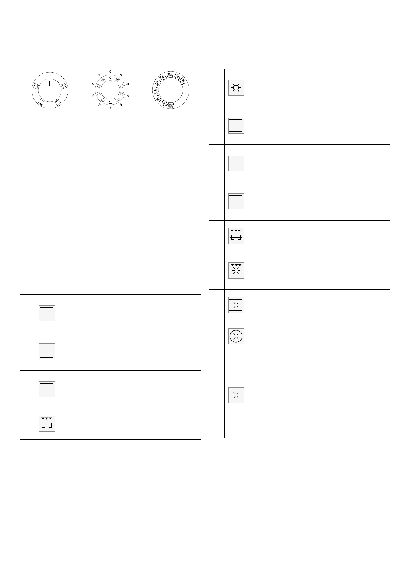
S. Selector S. Selector T. Thermostat
0
OFF
Command of the oven multifunction
S. Multifunction / static electric oven selector
T. Temperatures, from 100°F to 500°F, can be selected by
using this knob.
Turning on and o
Choose one of the cooking operations by turning the selector
(S) and adjust the
temperature with the thermostat (T).
We recommend putting into the oven aer preheating.
Function oven
Choose one of the cooking functions pag.35-36 by turning
the selector (S) and adjust the temperature (100°F to 500°F)
with the thermostat (T). If your model is equipped with a
programmer, prepare it for cooking.OVEN static
Function oven static
2
Normal static cooking
It is the oven’s classic function particularly suited to cooking
the following foods: pork chops, sausages, cod, braised
beef, game, roast veal, meringues and biscuits, baked fruit,
etc.
3
Cooking from underneath
This is the most suitable mode to nish the food cooking,
in particular confectionery (biscuits, meringues, leavened
cakes, fruit desserts, etc.) and other foods. Max temperature
F°430
4
Cooking from above
Especially suitable for browning and to give the nal touch
of colour to many foods; it is recommended for ham-
burgers, pork chops, veal steaks, sole, cuttlesh, etc. Max
temperature F°355
5
Closed door grill cooking
The suitable function for fast and deep grilling, to brown
and roast meats in general, llet steaks, Florentine steaks,
grilled sh and also grilled vegetables..
Function oven multifunction
1
Pizza cooking
This function is particularly suitable for cooking pizza,
focaccia and bread. The main source of heat is from the
bottom heating element that works in combination with the
oven’s other resistances.
2
Normal static cooking
It is the oven’s classic function particularly suited to cooking
the following foods: pork chops, sausages, cod, braised
beef, game, roast veal, meringues and biscuits, baked fruit,
etc.
3
Cooking from underneath
This is the most suitable mode to nish the food cooking,
in particular confectionery (biscuits, meringues, leavened
cakes, fruit desserts, etc.) and other foods. Max temperature
F°430
4
Cooking from above
Especially suitable for browning and to give the nal touch
of colour to many foods; it is recommended for ham-
burgers, pork chops, veal steaks, sole, cuttlesh, etc. Max
temperature F°355
5
Closed door grill cooking
The suitable function for fast and deep grilling, to brown
and roast meats in general, llet steaks, Florentine steaks,
grilled sh and also grilled vegetables.
6
Fan grill cooking
Particularly fast and deep with signicant energy savings,
this function is suitable for many foods such as pork chops,
sausages, pork or mixed spits, game, gnocchi alla romana,
etc.
7
Intensive cooking
Is the quick and intense cooking function for various
dishes; best for: baked sh, braised vegetables, spits, duck,
chicken, etc.
8
Multiple fan cooking
It is the function that allows simultaneous cooking of
dierent dishes without the smells blending; you can cook
lasagne, pizza, croissants and brioches, tarts, cakes, etc.
9
•
•
•
•
•
•
•
•
•
•
•
•
Quick Start
This function speeds up your oven’s pre-heating. We
suggest you use this function when you set a cooking
temperature from between 400 and 575 ° F. Use of the
QuickStart function for temperatures under 400 ° F is not
advantageous.
Once the oven has reached the temperature, select the
desired cooking function and the temperature.
WARNING: the Quick Start function is not suitable for
cooking foods, it is only for quickly pre-heating the oven.
DO NOT USE THE QUICK START FUNCTION FOR MORE
THAN TWENTY MINUTES.
24
Before the first use
Clean your hob with a damp cloth, and then dry the surface
thoroughly. Do not use detergent which risks causing bluetinted
colour on the glass surface.
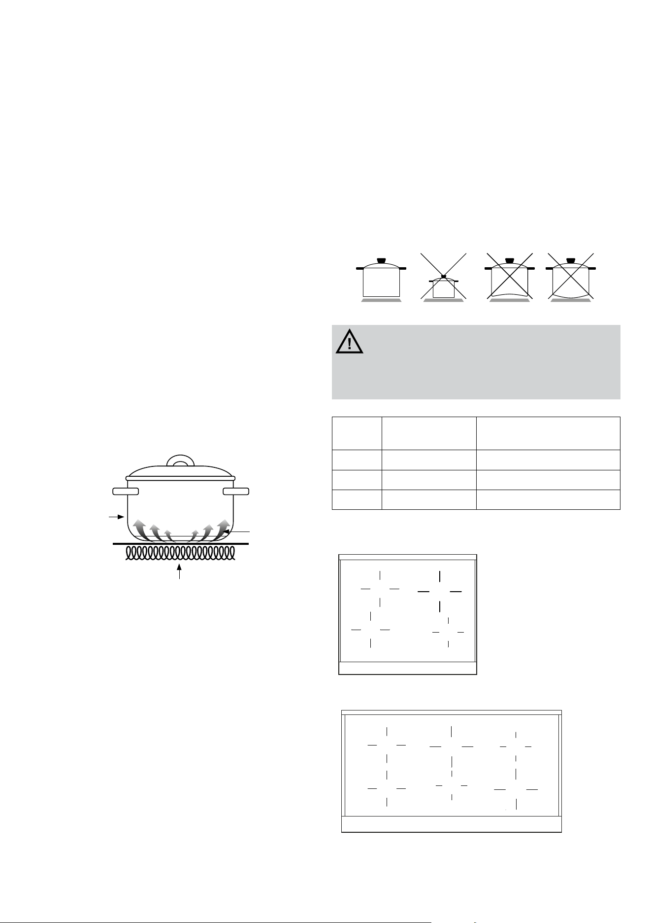
INDUCTION PRINCIPLE
An induction coil is located under each heating zone. When it
is engaged, it produces a variable electromagnetic field which
produces inductive currents in the ferromagnetic bottom plate
of the pan. The result is a heating-up of the pan located on the
heating zone.
Of course the pan has to be suitable:
- All ferromagnetics pans are recommended (please verify it
thanks a little magnet): cast iron and steel pans, enamelled
pans, stainless-steel pans with ferromagnetic bottoms…
- Are excluded : copper, pure stainless-steel, aluminium,
glass, wood, ceramic, stoneware,…
The induction heating zone adapts automatically the size of
the pan. With a too small diameter the pans doesn’t work. This
diameter is varying in function of the heating zone diameter.If
the pan is not suitable to the induction hob the display will show
[ U ].
Induction based
cookware
Induction
current/energy
Glass
ceramic plate
Electromagnetic coil
IMPORTANT
The ceramic hob remains hot for a long time after use. Do
not touch the hob with your hands or let children near it. The
residual heat indicator will remain lit until the hob has cooled
down.
If any cracks appear in the ceramic hob, disconnect the
appliance immediately from the mains and call an authorized
technical service centre.
The hob has cooking areas with different power values and
diameters.
The positions are clearly indicated by the rings during operation,
heat is located exclusively within these rings and the remaining
area stays cold.
Each cooking area is designed to operate with specific pans
for induction cooking, having a diameter just smaller than
the diameter of the chosen cooking area. The bottom of the
pan must be thick and flat. Its diameter must be as similar as
possible to that of the cooking ring. The surface of the hob and
the bottom of the pan must be kept clean.
Do not wet or overheat the plates.
- Avoid sudden changes of temperature on the ceramic hob.
For example, do not pour cold water onto the hot hob.
- Do not leave the pan handles sticking out as they could be
ipped accidentally.
- It is preferable not to cook on the ceramic hob with pans
that have been used on gas burners The ames will have
deformed the bottom of the pans.
WARNING
The glass ceramic cooking zone is warmed up from the heat of
the pan. To avoid injuries (burning) do not touch this area.
Burners Cooking area
(inch)
Electric power (watt)
A
ø 5”
3/4
1400W / Booster 1800W
B
ø 7”
1/4
1850W / Booster 2500W
C
ø 8”
11/16
2300W / Booster 3200W
B
C
B
A
B
C
A
B
A
C
INSTRUCTIONS FOR USE
Induction appliance
25
SWITCHING ON A COOKING AREA
A cooking area is switched on by pushing and turning the
relevant knob clockwise. The set power level appears on the
hob display (from 1 to 9).
SWITCHING OFF A COOKING AREA
A cooking area is switched o by turning the relevant knob
anticlockwise. The symbol [0] appears on the hob display for
3 seconds, then it disappears from the display changes to
the symbol [H], if the cooking area is still hot.
AUTOMATIC SWITCHING OFF OF THE DEVICE
The device switches o automatically if any conditions of
excess temperature (185°F) or errors in power supply occur.
BRIDGE function for the induction hob:
Place the pan in the middle of the two heating zones that will
be connected (the two equal-sized zones).
Turn the knobs of the two aected zones clockwise and until
the end of the stroke.
Hold them for 3 seconds to activate the function.
Adjust the power of the bridge with the front le area knob.
BOOSTER FUNCTION
The purpose of the booster function is to give more power to
a determined area in order to reduce the necessary cooking
time.
This function is activated by pushing and turning the knob
clockwise from position 0 (o) to the fi nal position (* fig. 13).
The symbol [P] appears on the display, meaning that the
booster function is activated.
The Booster function has a maximum duration of 10 minutes.
The area concerned then returns to level [9].
The Booster function ends before this time when:
- a lower power level is set
- the pan is removed
- there is overheating of the appliance or of the heating area
The Booster function has precedence over the “Heat-up”
function. This means that, if the heat-up function has been
activated in an area at the time of activating the Booster
function, the heat-up function will be interrupted.
RECOGNIZING THE PRESENCE OF A PAN
Each cooking area is designed to operate with specic pans
for induction cooking, having a diameter just smaller than the
diameter of the chosen cooking area. If the pan is not suitable,
the display for the area shows the symbol indicating absence
of the pan (U) and the appliance does not start up. This
prevents the appliance being switched on until a container is
placed on the coo king area, or until a container suitable for
induction is used. If the container used on the cooking area is
removed during this time, the area is switched o.
RESIDUAL HEAT INDICATION
If the cooking area is still very hot, even though it is switched
o, the symbol H appears on the display.
“HEAT-UP” FUNCTION
The Heat-up function, or quick heating, is available on each
cooking area. This means that for a well dened time the
cooking area works at maximum power and at the end of this
time the power is automatically brought to the set level. In this
case the duration depends on the set power level. The Heat-
up function is activated by pushing and turning the knob
anticlockwise from position 0 to the nal position. As soon
as the control is turned to the le, a letter [A] is shown on the
display for the area. Aer it has been activated you must set a
power level to continue cooking within 3 to 5 seconds; if this
is not done, the Heat-up function is interrupted.
KEY-LOCK FUNCTION
The Key-lock function is useful if there are children at home.
However, it is always advisable for an adult to be present
when the appliance is in operation. When the Key-lock
function is activated all the cooking areas are switched o
and they cannot be switched on accidentally.
The Key-lock function is activated, with the knobs in position
0, by turning the controls 1 and 2 simultaneously in an
counterclockwise direction.
INSTRUCTIONS FOR USE
Induction appliance
CAUTION
DO NOT TOUCH SURFACE UNITS OR
AREAS NEAR UNITS – Surface units
may be hot even though they are dark in
color. Areas near surface units may become
hot enough to cause
burns. During and aer use, do not touch,
or let clothing or other ammable materials
contact surface units or areas near units
until they have had sucient time to cool.
Among these areas is the glass surface of
the cooktop.
26
INSTRUCTIONS FOR USE
Induction appliance
Heating function 108°F AND 149°F
Turn the knob (A) clockwise. Between the o position (0) and
the power position (1) there is the position (u) which identies
the function for heating food at 108°F. Only for 4 and 6-zone
models: turn the knob (A) clockwise again.
Between the (u) position and the power position (1) there
is the position (U) which identies the function for heating
food at 149°F. The maximum time of use for both functions
is limited to 120 minutes. Both functions are prioritized over
the ‘HEAT-UP’ mode.
The Key-lock function is activated, with the knobs in position
0, by turning the controls 2 and 3 in a counterclockwise
direction. The letters [L][L][L][L] appear on the display. The
Key-lock function is deactivated by repeating the same
operation. The letters [O][F] appear on the display. If a knob is
turned when the key-lock function is active, the letters [L][L]
[L][L] appear on the disp.
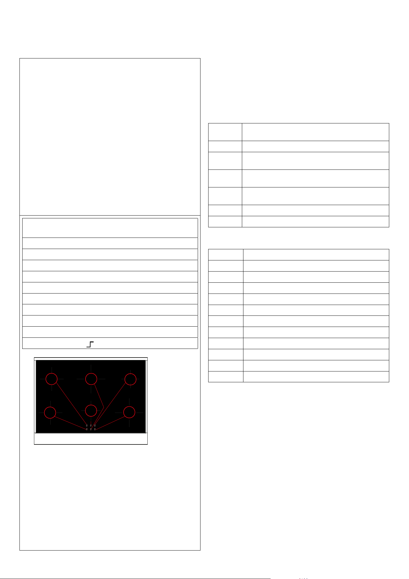
DISPLAY
A display is associated with each cooking area
Set power level: (1-9)
Food heating 108°F 149°F (U)
Booster: (P)
Heat-up: (A)
Residual heat: (H)
Pan absent or not suitable: (U)
External error: (E)
Fault: (F)
Key-lock function: [L][L][L][L]
Knob permanent rotation:
B
C
A
B
A
C
B
A
B
A
C
C
induction
Limit of the duration of operation
A maximum time of continuous operation is associated with
each cooking area.
This depends on the set power level. If the limit of the duration
of operation is reached, the respective area is switched o
Operating tablE (purely indicative values)
Knob
position
Type of cooking
1-2 melting butter, chocolate, etc.
2-4 heating small amounts of liquids, keeping food warm,
preparing sauces.
4-5 heating solid foods, thawing frozen foods, omelettes with 2-3
eggs, fruit and vegetables.
5-6 cooking meat and sh, pulses in sauces, dishes with water,
making jam.
6-7 roasting meat or sh, steaks, liver, eggs.
8-9 boiling large amounts of water, frying chips, etc.
Time limit operation table
Power Level Approximate limit of the duration of operation (hours)
U 2
1 6
2 6
3 5
4 5
5 4
6 1,5
7 1.5
8 1,5
9 1,5
P (10 min. [P], later 80 min. [9])
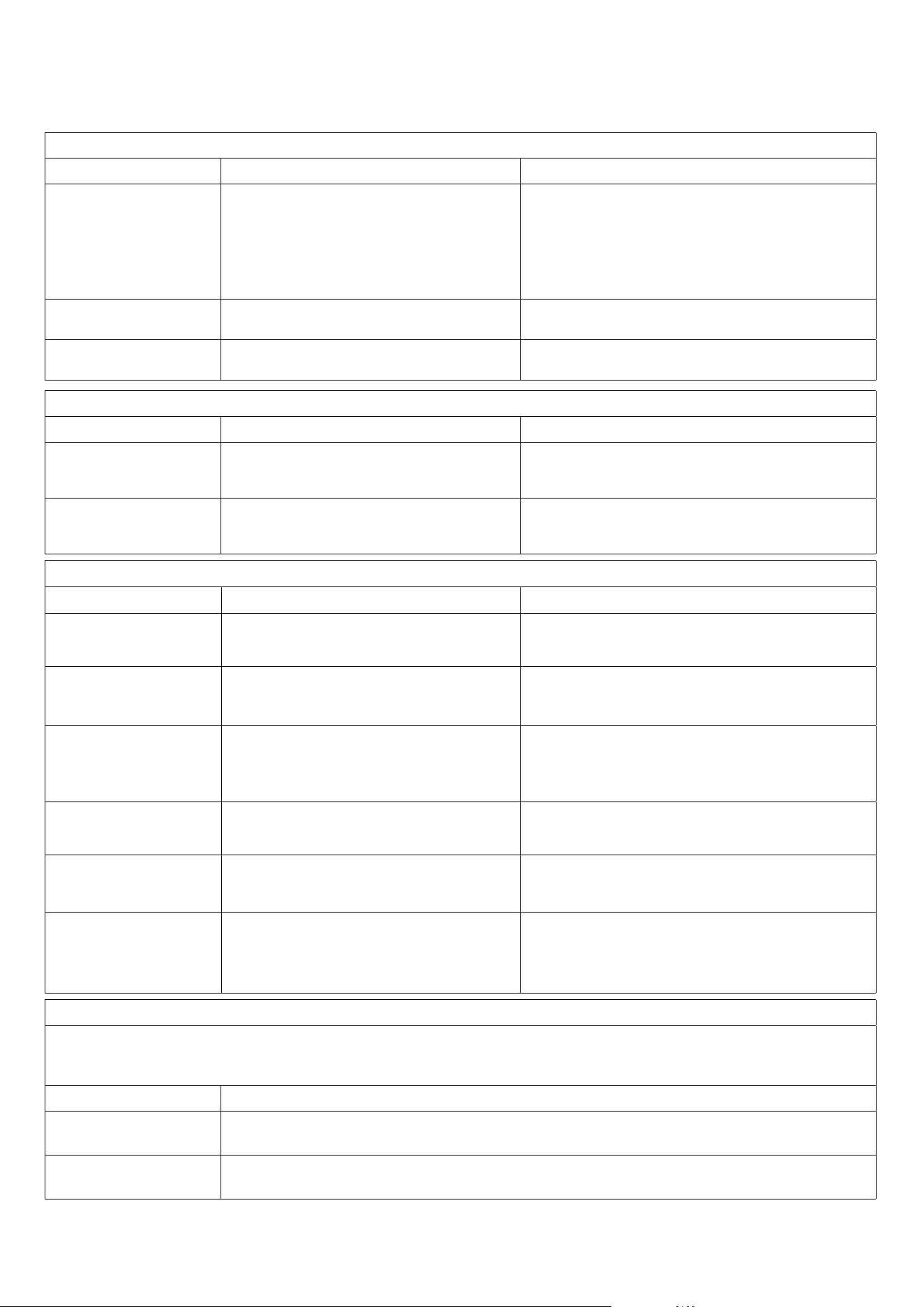
27
CLEANING AND MAINTENANCE
Recommendations for cleaning
OVEN
COMPONENT CLEANING METHOD WARNINGS
Oven interior
It is recommended to clean the oven aer each use. Dirt
is easier to clean if it is prevented from burning at high
temperatures repeatedly. Remove all removable parts
and wash them separately with warm water and non
abrasive detergent. Clean the cooking cavity with a so
cloth soaked in a solution of warm water and ammonia,
then rinse and dry.
Do not use steam cleaners for cleaning the oven interior. Do not
use abrasive/corrosive detergents or sharp metal tools to clean the
oven’s glass door, as they may damage the surface and cause it to
break.
Tray
Soak in a solution of warm water and mild soap. Dry
aer washing.
Remove food residues immediately aer use.
Racks
Clean with hot water and non-abrasive detergents or
with a suitable degreaser.
In case of baked-on and hardened dirt, it is recommended to soak
the racks for a few hours before cleaning.
FRONT PANEL
COMPONENT CLEANING METHOD WARNINGS
Stainless steel/glass surface
Clean the details with lukewarm water and non
corrosive liquid detergent, then dry them with a so
cloth or microber cloth.
Shine is maintained through periodic cleaning with specic
products typically available on the market. Never use abrasive
powders.
Painted surfaces
To maintain the characteristics of the painted parts,
it is necessary to clean them frequently with soapy
water.
Avoid leaving acidic or alkaline substances (vinegar, lemon
juice, salt, tomato juice, etc.) on the painted parts, and do not
wash the painted surfaces while they are still hot.
COOKTOP
COMPONENT CLEANING METHOD WARNINGS
Steel surfaces
Clean the details with warm water and non-abrasive
detergent. Dry with a so microber cloth.
Brilliance is maintained through regular cleaning with specic
products which can be found in commerce. Never use abrasive
powders.
Enameled surfaces
To maintain the characteristics of the enameled
surfaces it is necessary to regularly clean them with
soapy water.
Avoid leaving acidic or alkaline substances (vinegar, lemon juice,
salt, tomato juice, etc.) on enameled parts and washing them
when are still hot.
Cooktop grills
Remove the grills and wash them with warm water
and non-abrasive detergent. Carefully remove every
encrustation. Dry before placing them back on the
cooktop.
Acidic substances such as lemon juice or other acidic detergents
may permanently damage the enamel of the grills. Carefully
dry the grills with a cloth right aer the cleansing. It is not
recommended to wash them in the washing machine.
Spark plugs and
thermocouples
Clean with a humid cloth. If necessary, remove dry
dirt with a toothpick or a needle.
Spark plugs and thermocouples must be cleaned and checked
regularly.
Crowns, gas rings, and caps
Gas rings and caps are removable to allow easy
cleaning. Wash them with hot water and non-abrasive
detergent.
Carefully remove every encrustation and wait that they are
completely dried o. In the case of malfunctioning, make sure
that the holes in the external crown are always perfectly cleaned.
Induction or berglass
Remove light stains with a humid cloth and dry with a
so cloth.
Don’t clean with abrasive products. Don’t use any object that
could ruin the berglass top. Make sure that the bottom of the
pan is dry and clean, and that glass surface has no dust. Moving
the pan may scratch the glass. Immediately remove residual
sugar, jam and jelly to prevent damaging the glass.
DRAWER
Cleaning is the only maintenance that is required. Warning! Cleaning must be performed with the cooker disconnected from the power supply.
Do not use aggressive or abrasive cleaning products, abrasive sponges or sharp objects that can leave marks of abrasion. Do not use steam
cleaners for internal cleaning of the drawer.
COMPONENT CLEANING METHOD
Front panel
To clean the front panel, use specic cleaning products such as warm water and non-abrasive detergents. Apply a small
amount of product on a so cloth and rub on the surface..
Painted surfaces
Clean the inside of the drawer with a damp cloth. If it is very dirty, add a few drops of detergent (non-aggressive universal
degreaser) to the wash water. Clean the surface with a dry cloth to dry. Reuse the drawer only when it is completely dry.

28
CLEANING AND MAINTENANCE
Recommendations for cleaning
List with common types of soiling and recommendations
how to treat them:
Type of soiling Treatment
Slight soiling,
no burned residues
Wipe with a moist cloth (scotch), without
cleaning agent
Sticky soiling Remove with a scraper. Then wipe the heating
area with a moist cloth
Lime deposits, caused by
water which has boiled
over (induction hob)
Immediately scrape o the sugar, plastic or
aluminum foil residues thoroughly from the
hot cooking area, e.g. with a razor blade. Aer
removal of the residues, clean it with a cleaning
agent. If the heating area is soiled with residues
of sugar, plastic or aluminum foil cools down
without prior cleaning, the ceramic surface
might become deformed by pinheadsized pits.
List with common types of soiling and recommendations
how to treat them:
The cleaning of the Ceran glass is identical to other similar
surfaces like glass. Do not use corrosive or abrasive cleaning
agents, such as grill and oven-sprays, stain- and rust-removers,
scouring powder and rough sponges.
Before being cleaned, the Ceran glass must be cooled down.
Other maintenance and servicing work other than cleaning as
described here, must be done by authorized service
personnel.
Make sure that no liquid can enter in the induction unit.
A good maintenance of the induction cooker requires a regular
cleaning, care and servicing.
The operator has to ensure that all components relevant for
safety are in perfect working order at all times.
The cooker should be examined at least once a year by an
authorized technician.
CAUTION Do not open the induction unit, dangerous electric
voltage inside
The cookers may only be opened by authorized personnel.
29
4
3
2
1
5
Convection oven (indicative values)
DISH TEMP (°F)
4
3
2
1
5
TIME (MIN)
MEATS
Roast beef 680 / 360 2/3 40/50
Roast ox 340 / 370 2/3 40/60
Roast veal 320 / 360 2/3 65/90
Roast lamb 280 / 320 2 100/130
Rare roast beef 360 / 370 2/3 40/45
Roast hare 340 / 360 2/3 80/100
Roast rabbit 320 / 340 2 80/100
Roast turkey 320 / 340 2 160/240
Roast goose 320 / 360 2/3 120/160
Roast duck 340 / 360 2/3 100/160
Roast chicken 360 2/3 90/120
FISH 320 / 360 2/3 15/25
PATISSERIE
Fruit cake 360 / 390 2 40/50
Margherita cake 360 / 370 2 40/45
Brioches 340 / 360 2 40/60
Sponge cake 370 / 390 2 25/35
Donuts 320 / 360 2 35/45
Sweet pu pastry 360 / 390 2 20/30
Grape atbread 370 / 390 2 30/40
Strudel 320 2 25/35
Savoiardi biscuits 300 / 360 2 50/60
Apple fritters 360 / 390 2 18/25
Savoiardi pudding 340 / 360 2 30/40
BAKERY
Bread 360 / 390 3 45
Pizza 480 3 10/20
Toast 370 / 380 2 7
IMPORTANT: Introduce the food when the oven is preheated.
Grill cooking
For appliances with an electric grill, cooking is done with the door closed at
360°F. The food to be grilled should be placed on the corresponding grill,
preferably on the fourth rack.
COOKING CHART
Static oven (indicative values)
DISH TEMP (°F)
4
3
2
1
5
TIME (MIN)
MEATS
Roast beef 440 2/3 60/80
Roast ox 480 2/3 50/60
Roast veal 440 2/3 60/80
Roast lamb 440 2 40/50
Rare roast beef 450 2/3 50/60
Roast hare 490 2/3 40/50
Roast rabbit 490 2 40/50
Roast turkey 490 2 50/60
Roast goose 440 2/3 60/70
Roast duck 490 2/3 45/60
Roast chicken 490 2/3 40/45
FISH 390/440 1/2 15/25
PATISSERIE
Fruit cake 440 2 35/40
Margherita cake 350/390 2 50/60
Brioches 350/390 2 25/30
Sponge cake 430/480 2 20/30
Donuts 360/390 2 30/40
Sweet pu pastry 390/420 2 15/20
Grape atbread 490 2 25/35
Strudel 360 2 20/30
Savoiardi biscuits 360/390 2 40/50
Apple fritters 390/430 2 15/20
Savoiardi pudding 390/430 2 20/30
BAKERY
Bread 430 3 30
Pizza 480 3 10/20
Toast 480 3 5
IMPORTANT: Introduce the food when the oven is preheated.
Grill cooking
For appliances with an electric grill, cooking is done with the door closed at
360°F. The food to be grilled should be placed on the corresponding grill,
preferably on the fourth rack.
Position of cooking grids
There are 5 shelf position - 1 is the lowest and 5 is the highest near to the grill.
If cooking one dish use shelf position 3, if cooking more than one tray depending on the height
of the tray or food is suggested to cook on shelf positions 2 and 4.
Use the 4 and 5 shelf position for grilling and the grill pan in the botton shelf 1 to cath any drips.
The lower shelp position 1 can be used to slow cooking down or the temperature can be reduced.
30
INSTALLATION
Key
00 Black
11 Brown
22 Red
33 White
44 Yellow
45 Yellow-green
55 Grey
66 Blue
AA Electrical ignition transformer
C Commutator
CA Capacitor 1,05 µF
CCDF Fry-Top switch
CP Cooking probe
DM Dumper microonde
DV Dumper vapore
DS1 Burner control
DU Wax thermal actuator discharging steam
DY Display
EL Solenoid valve
EN Encoder
F Phase
F1 Phase 1
FLC LC Filter
FUSE Fuse 10A
HVD High voltage diode
K1 Earth wire terminal block
K2 Earth wire lower resistance
K3 Earth wire oven fan
K4 Earth wire circulating resistance
K5 Earth wire upper resistance
K6 Earth wire oven light 1
K7 Earth wire oven light 2
K8 Earth wire roaster
K9 Earth wire cooling fan.
K10 Earth wire commutator
K11 Earth wire oven thermostat
K12 Earth wire programmer/timer
K13 Earth wire grill resistance
K14 Earth wire piastra elettrica
K15 Earth wire frame
K16 Earth wire barbecue resistance
K17 Earth wire resistenza friggitrice
L1
Oven light
L2 Oven light
M Terminal block
MA Electrical ignition microswitch
MD Grill microswitch
MG Rotisserie
MGT Magnetron
MP Door microswitch
MMO Monitor microswitch for microwave
MPR Primary microswitch for microwave
MSEC Secondary microswitch for microwave
MT Micro cooling fan
MTK Water loading tank microswitch
MVT Cooling fan microswitch
N Neutral
NTC Temperature probe
P Timer\Clock - Timer\Programmer
PB Power board
PD Pump
PE Electric hotplate
PT1000 Temperature probe
R1 Upper resistance
R2 Lower resistance
R3 Grill resistance
R4 Circulating resistance
R5 Barbecue resistance
R6 Fryer resistance
RC Boiler heating element
RE Energy controller
RL Limit resistance
S1 Oven warning light
S2 Mains power warning light
S3 Grill warning light
S4 Cooling fan warning
S5 Barbecue warning light
S6 Electric hotplate warning light
S7 Rotisserie warning light
S8 Residual heat warning light
S9 Fryer warning light
SA Power supply board
SD Display board
SE Auxiliary power board
SI Interface board
SL Water level detector
SP Power board
SR Safety Relay
SWD Warming drawer control board
T Grill thermostat
TCO\TC1 Safety thermostat 318 °C (TCO)
TSPO Safety thermostat 90 °C
TF Oven thermostat
TR Fryer thermostat\ High voltage transformer
TS\TS1\
TS2
Safety thermostat
TST Tangential motor safety thermostat
TT Tangential thermostat
V\VR Oven fan
VT Cooler fan
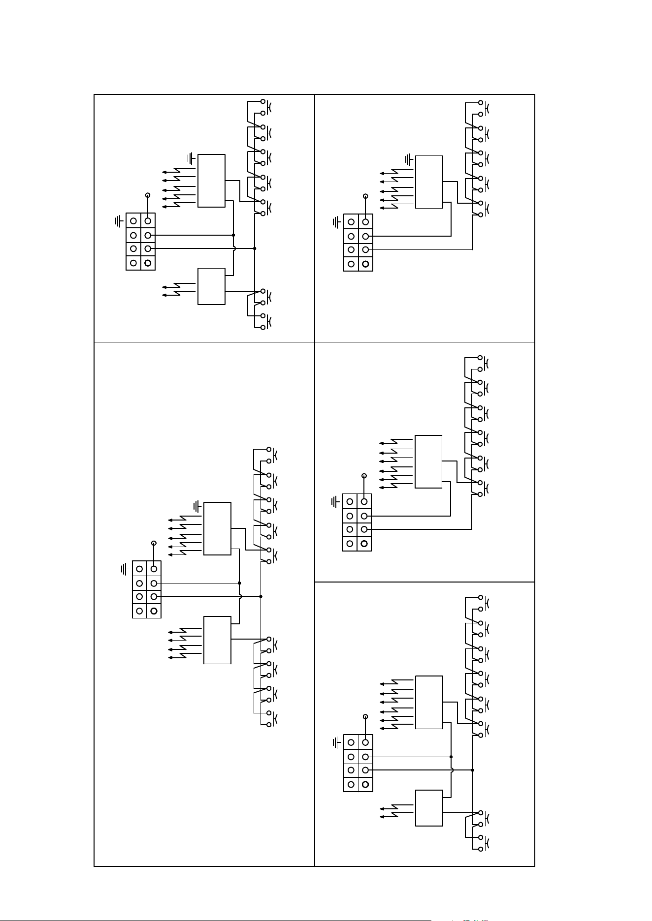
31
M
45
K14
33 22
AA
MA MA
SP
22
33
22
22
MA MA
2222
222222
MA
22
22
F1
N
33 22
AA
MA MA
SP
22
33
22
22
MA MA
2222
222222
MA MA
2222
2222
F
5 BURNERS
6 BURNERS
33 22
AA
MA MA
SP
22
33
22
22
MA MA
2222
222222
MA
22
22
AA
MA MA
SP
22
22
22
22
7 BURNERS
33 22
AA
MA MA
SP
22
33
22
22
MA MA
2222
222222
MA
22
22
AA
MA MA
SP
22
22
22
22
8 BURNERS
MA
22
22
33 22
AA
MA MA
SP
22
33
22
22
MA MA
2222
222222
MA
22
22
AA
MA MA
SP
22
22
22
22
9 BURNERS
MA
22
MA
22
M
45
K14
F1
N
F
M
45
K14
F1
N
F
22
33
33
M
45
K14
F1
N
F
M
45
K14
F1
N
F
33
22
ELECTRICAL SKETCHES
GAS HOB
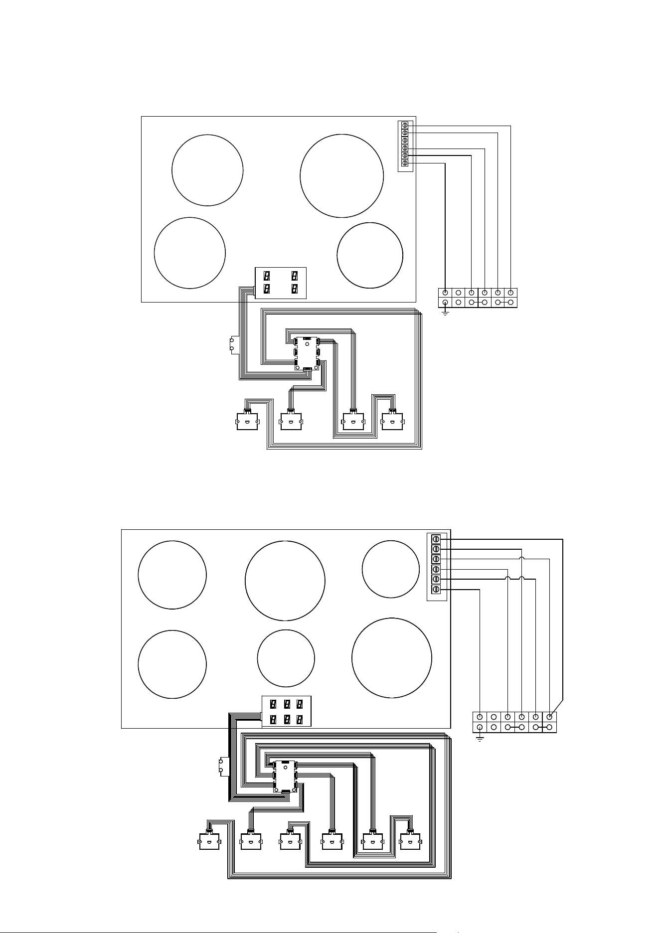
32
ELECTRICAL SKETCHES
4 INDUCTION ZONES
ELECTRICAL SKETCHES
6 INDUCTION ZONES
PE1
PE2
(1850 W)
(1850 W)
PE6
(1400 W)
PE5
(2300 W)
PE3
(2300 W)
PE4
(1400 W)
SI
5ER1ER 6ER2ER
RE3
RR
RC
RL
FR
FC
FL
RE4
1
2
3
4
5
M
22
00
00
22
45
N F F
F1
F1
22
22
22
22
00
00
0000
45
45
22
22
22
00
00
22 22
22
TS
M
22
22
00
00
45
PE1
PE2
PE4
PE3
(1850 W)
(1850 W)
(2300 W)
(1400 W)
1
2
3
4
5
SI
4ER1ER 3ER2ER
RR
RC
RL
FR
FC
FL
N F F
F1
F1
22
22
22
22
00
00
0000
45
45
TS
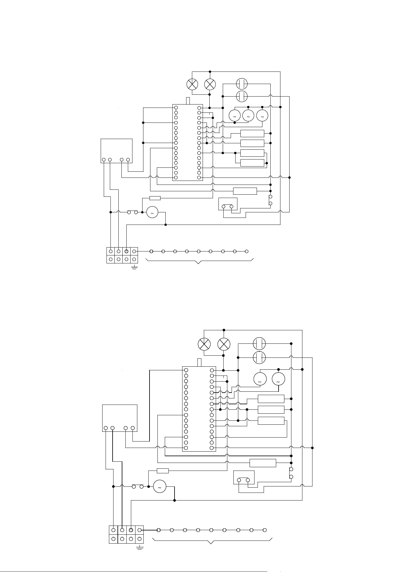
33
ELECTRICAL SKETCHES
U (P/N) 30...MP
U (P/N) I 30...MP
ELECTRICAL SKETCHES
U(P/N) 36MP - U(P-N) 361MP
U(P/N) I 36MP - U(P-N) I 361MP
C
5
4
8
6
7
11
9
10
C
E
G
M
I
L
3
12
N
D
F
H
O
13
2
A1
B
P
14
K1
45
K3 K5 K6
F F1
M
K7 K9 K13 K15K8
22
22
M
VT
22
P
IN
OUT
00
00
R4
11
55
R1
R2
11
00
00
00
R3
22
T
S1
S2
00
M
M
MG
VR
L1
L2
00
00
22
22
00
66
66
66
44
11
33
33
22
00
Q
15
N
TT
33
33
33
33
33
33
33
00
66
00
11
11
11
11
55
RL
TS
22
55
55
C
5
4
8
6
7
11
9
10
C
E
G
M
I
L
3
12
N
D
F
H
O
13
2
A 1
B
P
14
K1
45
K3 K5 K6
F F1
M
K7 K9 K13 K15K8
22
22
M
VT
22
P
IN
OUT
00
00
R4
11
55
R1
R2
11
00
00
00
R3
22
T
S1
S2
00
M
M
MG
VR
L1
L2
00
00
22
22
00
66
66
66
44
11
33
33
22
00
Q
15
N
TT
33
33
33
33
33
33
33
00
66
00
11
11
11
11
55
RL
TS
22
55
55
M
VR
R4
22
22
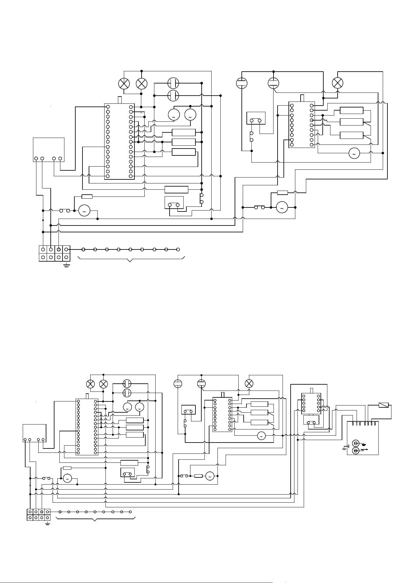
34
C mf
5
4
8
6
7
11
9
10
C
E
G
M
I
L
3
12
N
D
F
H
O
13
2
A1
B
P
14
K1
45
K3 K5 K6
F F1
M
K7 K9 K13 K15K8
22
22
M
VT
22
P
IN
OUT
00
00
R4 mf
11
55
R1 mf
R2 mf
11
00
00
00
R3 mf
22
T
S1
S2
00
M
M
MG
VR
L1
L2
00
00
22
22
00
66
66
66
44
11
33
33
22
00
Q
15
11
M
33
66
3
2
R1
R2
00
00
66
66
00
00
00
6
4
5
9
7
8
A
B
F
D
I
G
H
1
R3
11
66
00
11
22
00
66
00
11
11
00
22
22
00
00
M
VT
11
S1
S2
L1
C st
MG
TT
N
TT
33
33
33
33
33
33
33
00
66
00
11
11
11
11
55
RL
22
22
22
22
00
00
00
22
TS
22
33
33
33
33
33
TS
RL
22
55
55
55
55
55
55
T
C mf
5
4
8
6
7
11
9
10
C
E
G
M
I
L
3
12
N
D
F
H
O
13
2
A 1
B
P
14
K1
45
K3 K5 K6
F F1
M
K7 K9 K13 K15K8
22
22
M
VT
22
P
IN
OUT
00
00
R4 mf
11
55
R1 mf
R2 mf
11
00
00
00
R3 mf
22
T
S1
S2
00
M
M
MG
VR
L1
L2
00
00
22
22
00
66
66
66
44
11
33
33
22
00
Q
15
11
M
33
66
3
2
R1
R2
00
00
66
66
00
00
00
6
4
5
9
7
8
A
B
F
D
I
G
H
1
R3
11
66
00
11
22
00
66
00
11
11
00
22
22
00
00
M
VT
S1
S2
L1
C st
MG
TT
N
TT
33
33
33
33
33
33
33
00
66
00
11
11
11
11
55
RL
22
22
22
22
00
00
00
22
TS
22
33
33
33
33
TS
22
55
55
55
11
55
55
T
C cdf
S2SCS1NH2H1A
J3
TF2
TF1
EL
DS1
45
SP
T
55
55
22
22
22
22
33
33
33
22
11
11
11
11
11
00
00
00
00
RL
55
55
55
22
11
11
11
11
4
3
5
B
C
E
2
D
A
1
ELECTRICAL SKETCHES
U (P/N) 48...MP
U (P/N) I 48...MP
ELECTRICAL SKETCHES
U (P/N) 48...S MP
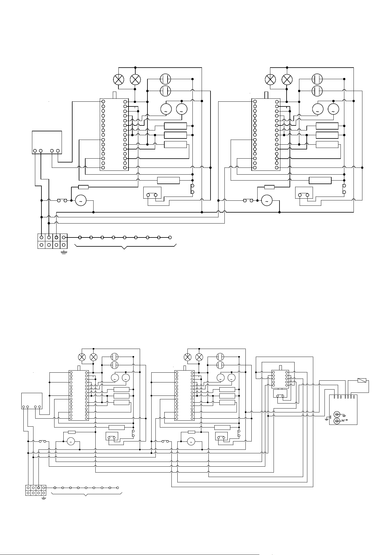
35
ELECTRICAL SKETCHES
U (P/N) 60...MP
ELECTRICAL SKETCHES
U (P/N) 60... S MP
C
5
4
8
6
7
11
9
10
C
E
G
M
I
L
3
12
N
D
F
H
O 13
2
A1
B
P
14
K1
45
K3 K5 K6
F F1
M
K7 K9 K13 K15K8
22
22
M
VT
22
P
IN
OUT
00
00
R4
11
55
R1
R2
11
00
00
00
R3
22
T
S1
S2
00
M
M
MG
VR
L1
L2
00
00
22
22
00
66
66
66
44
11
33
33
22
00
Q
15
N
TT
33
33
33
33
33
33
33
00
66
00
11
11
11
11
55
RL
TS
22
55
55
C mf
5
4
8
6
7
11
9
10
C
E
G
M
I
L
3
12
N
D
F
H
O 13
2
A1
B
P
14
22
M
VT
00
R4
11
55
R1
R2
11
00
00
00
R3
22
T
S1
S2
00
M
M
MG
VR
L1
L2
00
00
22
22
00
66
66
66
44
11
33
33
Q
15
TT
33
33
33
33
33
33
33
66
00
11
11
11
11
55
RL
TS
22
55
55
22
22
00
00
C
5
4
8
6
7
11
9
10
C
E
G
M
I
L
3
12
N
D
F
H
O 13
2
A 1
B
P
14
K1
45
K3 K5 K6
F F1
M
K7 K9 K13 K15K8
22
22
M
VT
22
P
IN
OUT
00
00
R4
11
55
R1
R2
11
00
00
00
R3
22
T
S1
S2
00
M
M
MG
VR
L1
L2
00
00
22
22
00
66
66
66
44
11
33
33
22
00
Q
15
N
TT
33
33
33
33
33
33
33
00
66
00
11
11
11
11
55
RL
TS
22
55
55
C mf
5
4
8
6
7
11
9
10
C
E
G
M
I
L
3
12
N
D
F
H
O 13
2
A 1
B
P
14
22
M
VT
00
R4
11
55
R1
R2
11
00
00
00
R3
22
T
S1
S2
00
M
M
MG
VR
L1
L2
00
00
22
22
00
66
66
66
44
11
33
33
Q
15
TT
33
33
33
33
33
33
33
66
00
11
11
11
11
55
TS
22
11
55
22
22
00
00
C cdf
S2SCS1NH2H1A
J3
TF2
TF1
EL
DS1
45
SP
T
55
55
22
22
22
22
33
33
33
11
11
11
00
00
00
00
22
22
11
11
11
55
55
55
11
11
11
11
4
3
5
B
C
E
2
D
A
1
22
55
55
55
11
11
11
11
11
11
11
11
11
11
22
22
22
22
RL
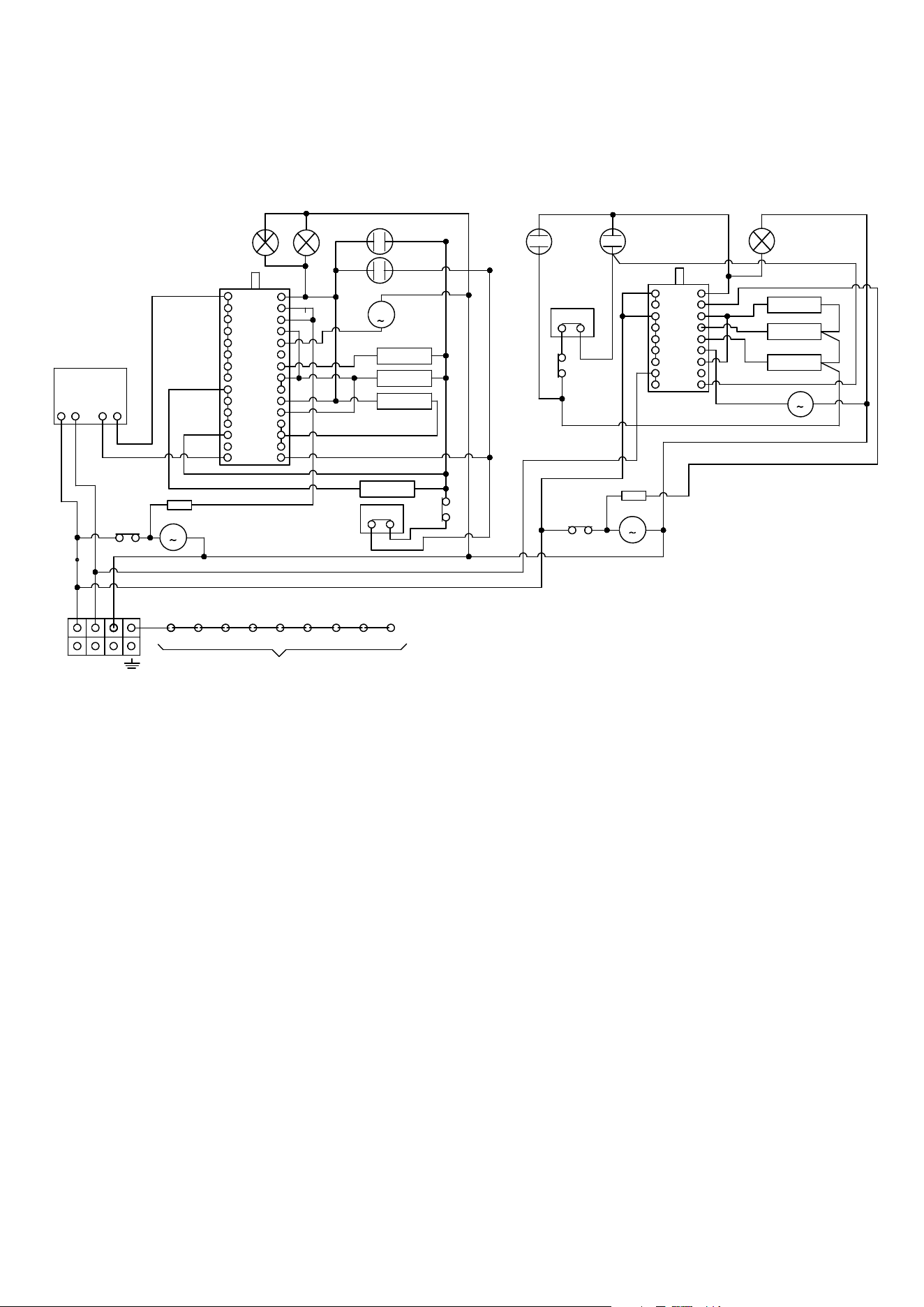
36
C mf
5
4
8
6
7
11
9
10
C
E
G
M
I
L
3
12
N
D
F
H
O
13
2
A1
B
P
14
K1
45
K3 K5 K6
F F1
M
K7 K9 K13 K15K8
22
22
M
VT
22
P
IN
OUT
00
00
R4 mf
11
55
R1 mf
R2 mf
11
00
00
00
R3 mf
22
T
S1
S2
00
M
VR
L1
L2
00
00
22
22
00
66
66
66
44
11
33
33
22
00
Q
15
11
M
33
66
3
2
R1
R2
00
00
66
66
00
00
00
6
4
5
9
7
8
A
B
F
D
I
G
H
1
R3
11
66
00
11
22
00
66
00
11
11
00
22
22
00
00
M
VT
11
S1
S2
L1
C st
MG
TT
N
TT
33
33
33
33
33
33
00
66
00
11
11
11
11
55
RL
22
22
22
22
00
00
00
22
TS
22
33
33
33
33
33
TS
RL
22
55
55
55
55
55
55
T
ELECTRICAL SKETCHES
U (P/N/) D 36...MP - U (P/N) D I 36...MP
U (P/N/) D 40...MP - U (P/N) D I 40...MP
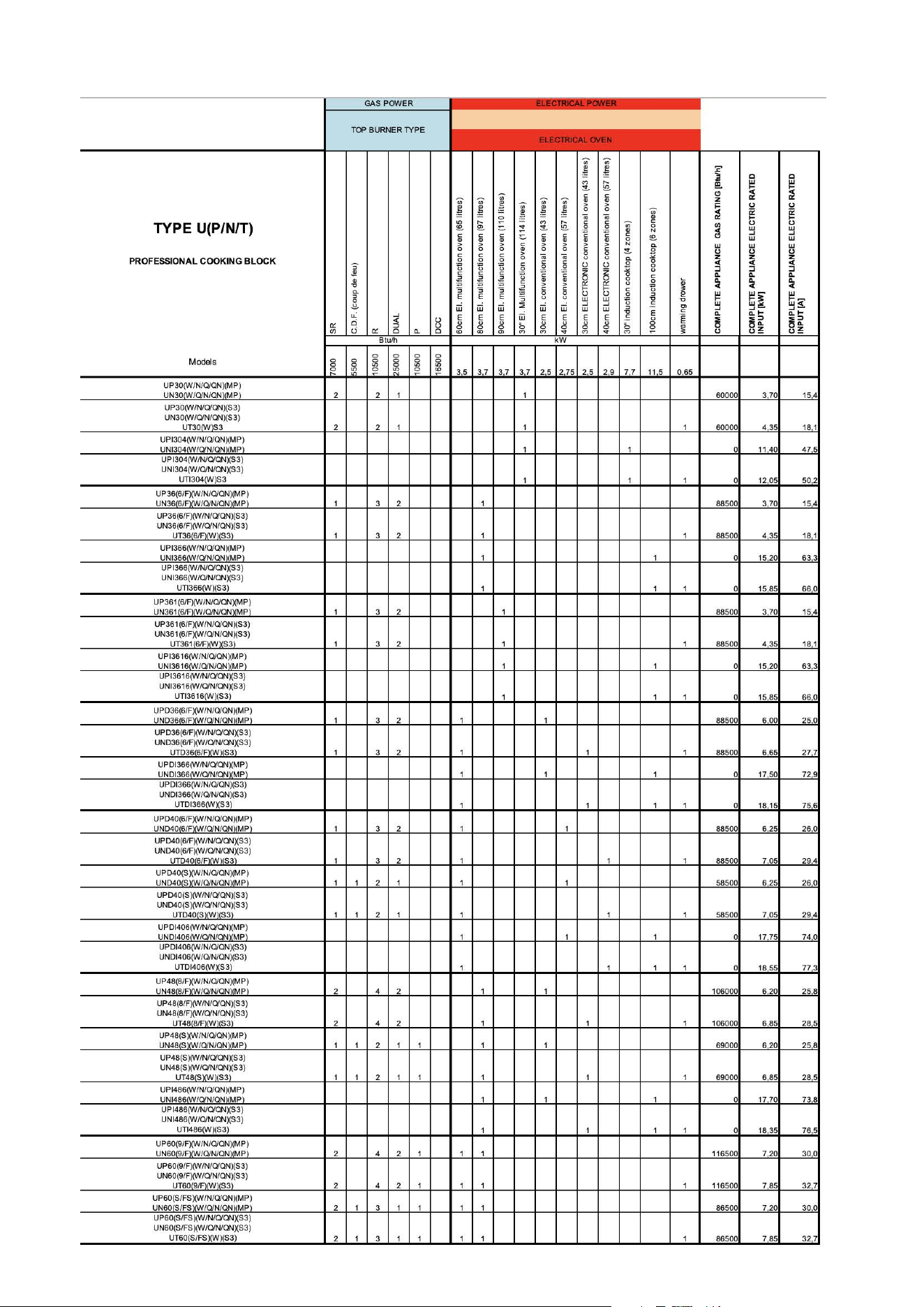
37
ELECTRICAL AND GAS POWER TABLE
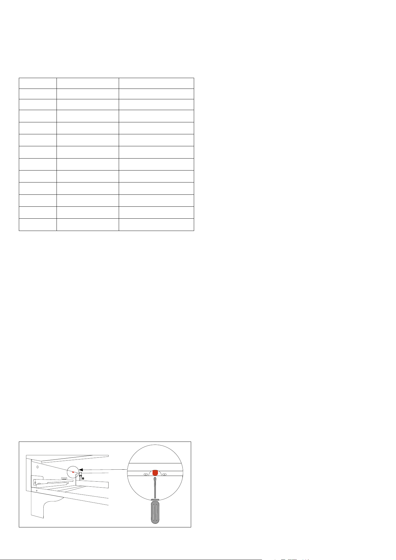
38
NOTE
Injectors for a device installed at an altitude above 2000 ft
List with common types of soiling and recommendations
how to treat them:
BURNERS GAS ORIFICE SIZE (1/100) mm
SR NATURAL (A) 117
R NATURAL (A) 141
DCC NATURAL (A) 185
DUAL NATURAL (A) 74+215
P NATURAL (A) 141
CDF NATURAL (A) 108
SR PROPANE (E) 74
R PROPANE (E) 87
DCC PROPANE (E) 112
DUAL PROPANE (E) 43+130
P PROPANE (E) 88
CDF PROPANE (E) 62
Safety Warnings - Thermostat
The cooker is tted with a safety thermostat that stops the ope-
ration in case the oven temperature rises too high. Each oven
has its own device. Aer the appliance has cooled down, it is
possible to try to restart it (if the safety thermostat tripped) by
manually resetting the contact. To perform the manual reset
follow this procedure:
First of all, disconnect the appliance from the mains by pulling
the plug from the wall socket or switching OFF the bipolar swi-
tch in the house wiring.
Open and remove the drawer under the ovens (pull outwards
and li), or remove the front panel (pull outwards to disengage
the spring pins).
Locate the safety thermostat, screwed to the chassis on the
side and in backward position (for cookers with only one oven it
is on the le side). See picture A
Insert from underneath upwards the point of a sharp object
(e.g. a pen) into the thermostat recess until a click is heard. See
picture B
Reassemble the drawer or the front panel and connect again
the appliance to the mains.
Check if the oven works. (If not, it is necessary to call the
Customer Service).

39

ilve.com
ILVE S.p.A Via Antoniana, 100 — 35011 — Campodarsego (PD) Italy
T. +39 049 9200990 / Email: [email protected]
cod. EI33960440000EN 48/2025