1
PRINTED 1120 100338053_2000536201C
ALL TECHNICAL AND WARRANTY QUESTIONS: SHOULD BE DIRECTED TO THE LOCAL DEALER FROM WHOM THE WATER HEATER WAS
PURCHASED. IF YOU ARE UNSUCCESSFUL, CALL THE TECHNICAL SUPPORT PHONE NUMBER SHOWN ON THE WATER HEATER LABELING.
KEEP THIS MANUAL IN THE POCKET ON HEATER FOR FUTURE REFERENCE WHENEVER MAINTENANCE
ADJUSTMENT OR SERVICE IS REQUIRED.
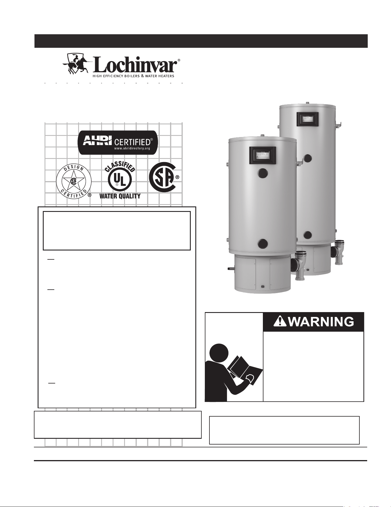
Instruction Manual
COMMERCIAL GAS WATER HEATERS COMMERCIAL GAS WATER HEATERS
Phone: 1-800-722-2101 • Fax: 615-547-1000
Technical Service email: [email protected]
www.Lochinvar.com
300 Maddox Simpson Parkway
Lebanon, TN 37090
LOW LEAD
CONTENT
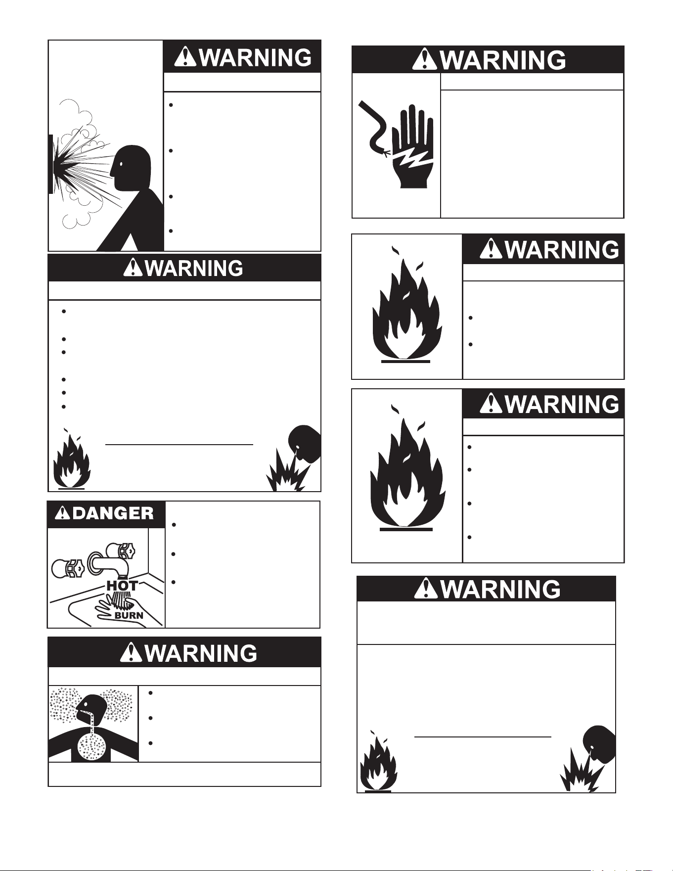
WARNING: If the information in these
instructions is not followed exactly, a fire
or explosion may result causing property
damage, personal injury or death.
Do not store or use gasoline or other
flammable vapors and liquids in the
vicinity of this or any other appliance.
WHAT TO DO IF YOU SMELL GAS:
Do not try to light any appliance.
Do not touch any electrical switch; do
not use any phone in your building.
Immediately call your gas supplier
from a neighbor’s phone. Follow the
gas supplier’s instructions.
If you cannot reach your gas supplier,
call the fire department.
Installation and service must be
performed by a qualified installer,
service agency or the gas supplier.
•
•
•
•
Thank you for buying this energy ecient water
heater. We appreciate your condence in our
products.
POWER DIRECT VENT GAS MODELS
WITH DIRECT SPARK IGNITION
MODELS
SC(N,L)(130,150)-035
SC(N,L)(130,150,175,199)-050
NATURAL GAS & PROPANE
Read and understand this instruction
manual and the safety messages
herein before installing, operating or
servicing this water heater.
Failure to follow these instructions and
safety messages could result in death
or serious injury.
This manual must remain with the
water heater.
• For Your Safety •
AN ODORANT IS ADDED TO THE GAS USED
BY THIS WATER HEATER.

2
CONTENTSCONTENTS
SAFE INSTALLATION, USE AND SERVICE ............................ 3
APPROVALS ............................................................................... 3
GENERAL SAFETY INFORMATION .........................................4
Precautions ..............................................................................4
Grounding Instructions .............................................................4
Limiting the Risk of Scalding ....................................................4
INSTALLATION REQUIREMENTS FOR THE
COMMONWEALTH OF
MASSACHUSETTS .................................................................... 7
INTRODUCTION ........................................................................8
Abbreviations Used ..................................................................8
Qualications ............................................................................8
Preparing For The Installation .................................................. 8
DIMENSIONS AND CAPACITY DATA ....................................... 9
Rough In Dimensions: All Models ............................................9
DIMENSIONS AND CAPACITY DATA ..................................... 10
FEATURES AND COMPONENTS ........................................... 11
34 Gallon Unit ........................................................................ 11
50 Gallon Unit ........................................................................12
Blocked Outlet Switch ...........................................................13
Blocked Intake Switch ...........................................................13
Water Heating Enable/Disable Switch....................................14
Spark Igniter ........................................................................... 14
Conguration Key ...................................................................14
INSTALLATION CONSIDERATIONS ......................................15
Locating the Water Heater .....................................................15
Insulation Blankets .................................................................16
Combustion Air And Ventilation ..............................................16
Corrosion and Water Quality .................................................. 17
INSTALLATION REQUIREMENTS .........................................18
Gas Supply Systems .............................................................. 18
Supply Gas Regulator ............................................................18
Power Supply .........................................................................18
Dedicated Power Wiring and Breakers ..................................19
Power Fluctuations and Electrical Noise ................................ 19
Mixing Valves .........................................................................19
Circulation Pumps ..................................................................19
Dishwashing Machines ..........................................................19
Space Heating And Potable Water System ............................ 19
Storage Tank Installation ........................................................ 20
Solar Installation .....................................................................20
Closed Water Systems ........................................................... 20
Thermal Expansion ................................................................20
Temperature-Pressure Relief Valve .......................................21
T&P Valve Discharge Pipe Requirements: ............................. 21
Condensate DRAIN ................................................................22
VENTING INSTALLATION .......................................................23
Vent Installation Considerations ............................................. 23
General Venting Instructions ..................................................23
Approved Vent/Intake Material ...............................................23
Polypropylene Installations ....................................................24
Vent Pipe Installation ..............................................................24
Integrated Filter Installation .................................................... 26
Direct Vent Air Intake Moisture Protection ..............................26
Horizontal Vent Terminal Installation ...................................... 27
Vertical Vent Terminal Installation .......................................... 27
Flat Roof Installation ..............................................................28
Concentric Vent Installation ....................................................31
Venting Multiple Units .............................................................31
WATER HEATER INSTALLATION ...........................................33
Condensate Drain Installation ................................................33
Supply Gas Line Installation ...................................................33
Gas Line Leak Testing ............................................................ 35
Purging ................................................................................... 35
Electrical Wiring .....................................................................35
Enable/Disable Circuit
(For Building Management Systems) ..................................... 35
Water Line Connections ......................................................... 36
T&P Valve Discharge Pipe ..................................................... 37
TEMPERATURE REGULATION .............................................. 38
High Temperature Limit Control (ECO) .................................. 38
Thermostat Control ................................................................38
CONTROL SYSTEM OPERATION ..........................................39
Limiting the Risk of Scalding ..................................................39
Overview ................................................................................39
Control System Navigation .....................................................39
Lockout Function .................................................................... 39
The Desktop Screen ..............................................................39
START UP .................................................................................49
Start Up Conditions ................................................................49
Prior To Start up .....................................................................49
Filling The Water Heater ........................................................49
Initial Start Up .........................................................................49
Checking The Firing Rate ......................................................52
To Turn O Gas Supply .......................................................... 52
Gas Input Rate .......................................................................52
High Altitude Installations ....................................................... 52
TROUBLESHOOTING .............................................................53
Installation Checklist ..............................................................53
Condensate Drain ..................................................................53
Electrical Connections ............................................................53
Sequence Of Operation .........................................................53
Operational Problems ............................................................55
Rough Starting, Rough Operation .......................................... 55
Momentary Ignition .................................................................55
Not Enough Or No Hot Water .................................................55
Water Is Too Hot .....................................................................55
Replacement Parts .................................................................56
Fault And Alert Conditions ......................................................56
LEAKAGE CHECKPOINTS .....................................................58
Water Leak Detection .............................................................58
PERIODIC MAINTENANCE.....................................................59
Venting System Inspection ..................................................... 59
Integrated Filter Preventative Maintenance ...........................59
Temperature-Pressure Relief Valve Test ................................ 60
Draining and Flushing ............................................................60
Sediment and Lime Scale Removal .......................................61
Burner Operation And Inspection ........................................... 61
Burner Flame Inspection ........................................................61
Anode Rod Inspection ............................................................ 62
DIAGRAMS ...............................................................................63
3
SAFE INSTALLATION, USE AND SERVICESAFE INSTALLATION, USE AND SERVICE
The proper installation, use and servicing of this water heater is
extremely important to your safety and the safety of others.
Many safety-related messages and instructions have been provided
in this manual and on your own water heater to warn you and others
of a potential injury hazard. Read and obey all safety messages
and instructions throughout this manual. It is very important that the
meaning of each safety message is understood by you and others
who install, use, or service this water heater.
DANGER
WARNING
CAUTION
CAUTION
DANGER indicates an imminently
hazardous situation which, if not avoided,
will result in injury or death.
This is the safety alert symbol. It is used to alert you to
potential personal injury hazards. Obey all safety
messages that follow this symbol to avoid possible
injury or death.
WARNING indicates a potentially hazardous
situation which, if not avoided, could result
in injury or death.
CAUTION indicates a potentially hazardous
situation which, if not avoided, could result in
minor or moderate injury.
CAUTION used without the safety alert
symbol indicates a potentially hazardous
situation which, if not avoided, could result in
property damage.
All safety messages will generally tell you about the type of hazard,
what can happen if you do not follow the safety message, and how
to avoid the risk of injury.
APPROVALSAPPROVALS
LOW LEAD
CONTENT
4
GENERAL SAFETY INFORMATIONGENERAL SAFETY INFORMATION
PRECAUTIONS
DO NOT USE THIS water heater IF ANY PART HAS BEEN
EXPOSED TO FLOODING OR WATER DAMAGE. Immediately call
a qualied service technician to inspect the water heater and to make
a determination on what steps should be taken next.
If the unit is exposed to the following, do not operate heater until all
corrective steps have been made by a qualied service technician.
1. External re.
2. Damage.
3. Firing without water.
GROUNDING INSTRUCTIONS
This water heater must be grounded in accordance with the National
Electrical Code and/or local codes. These must be followed in all cases.
Failure to ground this water heater properly may also cause erratic
control system operation.
This water heater must be connected to a grounded permanent
wiring system; or an equipment grounding conductor must be run
with the circuit conductors and connected to the equipment grounding
terminal or lead on the water heater.
LIMITING THE RISK OF SCALDING
For a variety of reasons, water heaters can produce water that is
much hotter than its temperature setting. Take precautions to prevent
this higher temperature water from reaching the water xtures.
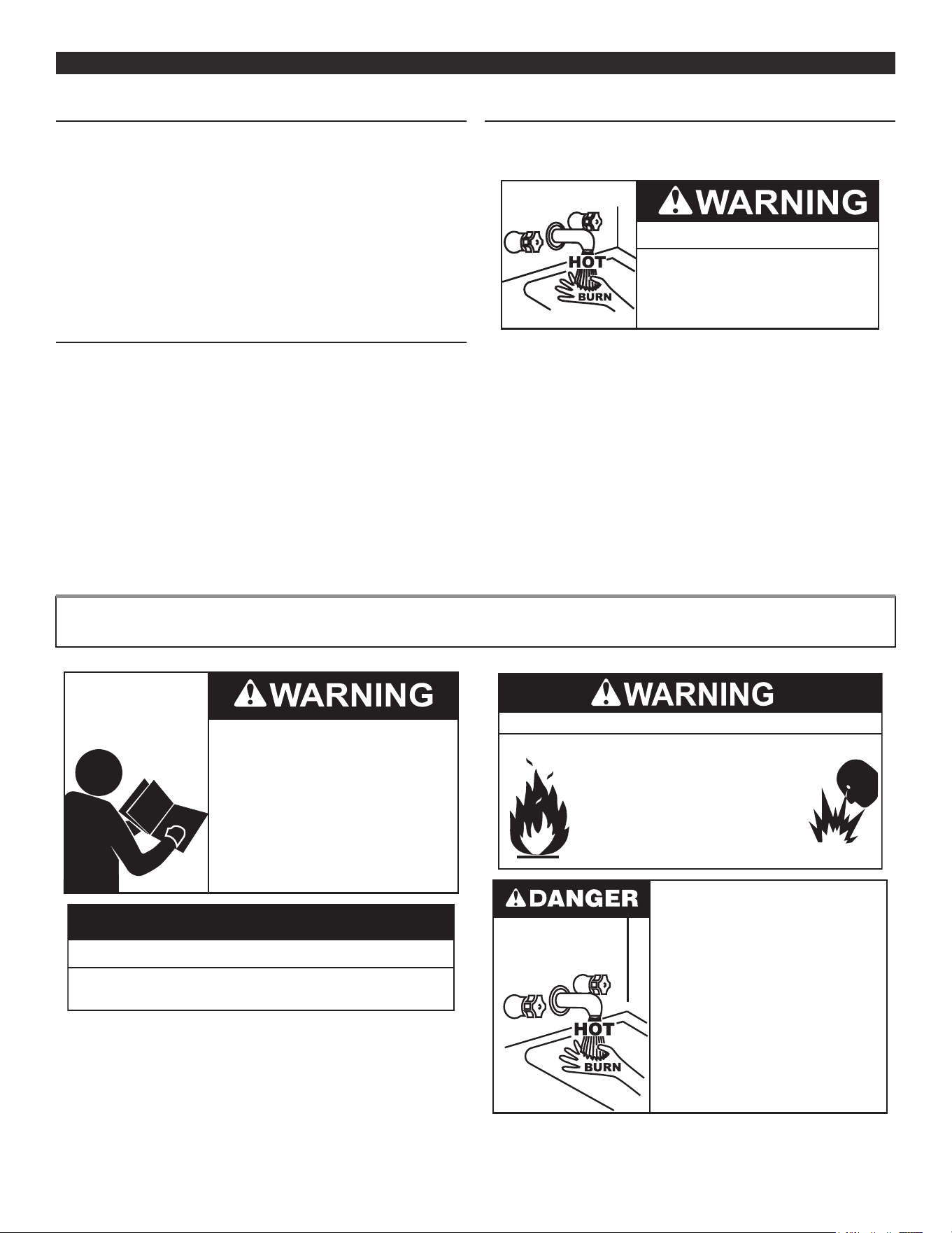
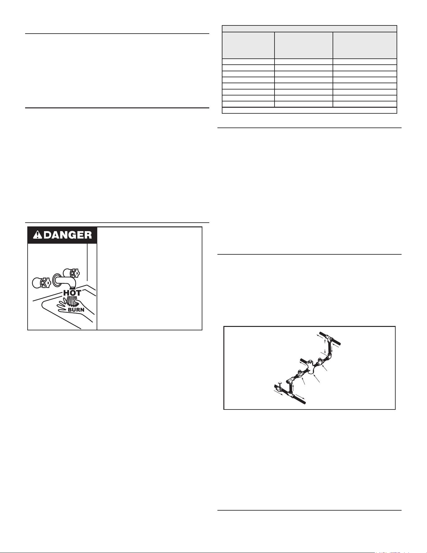
Burn Hazard
To reduce the risk of unusually hot
water reaching the fixtures in the
house, install thermostatic mixing
valves at each point of use.
According to a national standard (ASSE 1070) and many local
plumbing codes, the water heater’s gas control valve should not be
used as the sole means to regulate water temperature and avoid
scalds.
A properly adjusted thermostatic mixing valve at each point of use
allows you to set the tank temperature to a higher setting without
increasing risk of scalds. A higher temperature setting allows the
tank to provide much more hot water and can help provide proper
water temperatures for appliances such as dishwashers and washing
machines.
Higher tank temperatures (140°F) also kill bacteria that cause a
condition known as “smelly water” and can reduce the levels of
bacteria that cause water-borne diseases.
VERIFY THE POWER TO THE WATER HEATER IS TURNED OFF BEFORE PERFORMING ANY SERVICE PROCEDURES. THE ENABLE/DISABLE
SWITCH AT THE BASE OF THE WATER HEATER DISABLES THE 24 VOLT GAS CONTROL VALVE. ELECTRICAL SUPPLY MUST BE TURNED OFF AT
CIRCUIT BREAKER SERVING WATER HEATER.
Read and understand this instruction
manual and the safety messages
herein before installing, operating or
servicing this water heater.
Failure to follow these instructions and
safety messages could result in death
or serious injury.
This manual must remain with the
water heater.
Property Damage Hazard
All water heaters eventually leak.
•
Do not install without adequate drainage.
•
CAUTION
Fire and Explosion Hazard
•
Improper use can result in fire or
explosion.
Read the instruction manual before
installing, using, or servicing the water
heater.
•
Maintain required clearances to
combustibles.
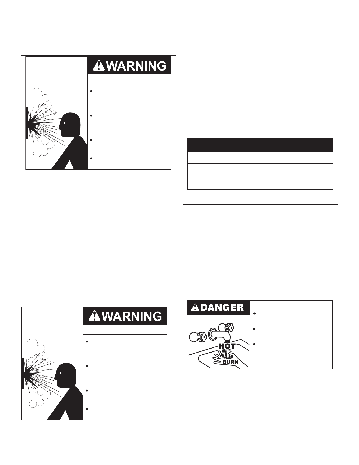
Water temperature over 125°F (52°C)
can cause severe burns instantly
resulting in severe injury or death.
Children, the elderly and the
physically or mentally disabled are at
highest risk for scald injury.
Feel water before bathing or
showering.
Temperature limiting devices such as
mixing valves must be installed
when required by codes and to
ensure safe temperatures at fixtures.
5
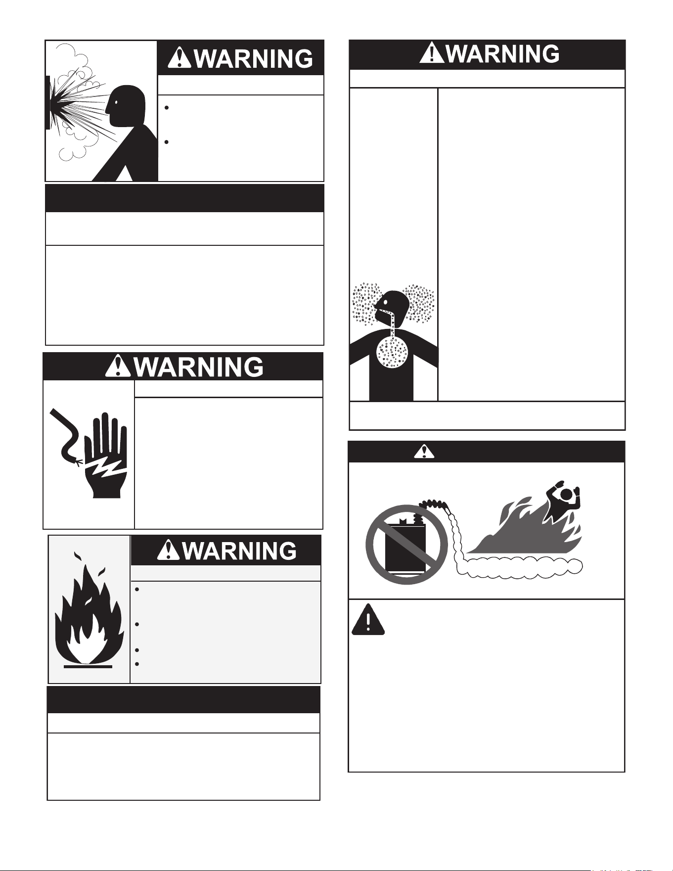
Explosion Hazard
Overheated water can cause
water tank explosion.
Properly sized Temperature -
Pressure Relief Valve must be
installed in the opening provided.
Improper installation, use and service may result
in property damage.
Do not operate water heater if exposed to flooding or water
damage.
•
Install in location with drainage.
•
Fill tank with water before operation.
•
Properly sized thermal expansion tanks are required on all
closed water systems.
•
Refer to this manual for installation and service.
CAUTION
Turn off power at the branch circuit
breaker serving the water heater
before performing any service.
Electrical Shock Hazard
•
Label all wires prior to disconnecting
when performing service. Wiring errors
can cause improper and dangerous
operation.
•
Verify proper operation after servicing.
•
Failure to follow these instructions can
result in personal injury or death.
•
Fire and Explosion Hazard
Turn off gas lines during installation.
Contact a qualified installer or service
agency for installation and service.
Excessive gas pressure to gas valve can
cause serious injury or death.
Do not use water heater with any gas
other than the gas shown on the rating
label.
Property Damage Hazard
● Avoid water heater damage.
● Install thermal expansion tank if necessary.
● Do not apply heat to cold water inlet.
● Contact qualified installer or service agency.
CAUTION
Breathing Hazard - Carbon Monoxide Gas
•
Install vent system in accordance with codes.
•
Do not operate water heater if any part has been
exposed to flooding or water damage.
•
High altitude models should be installed at
elevations
above
5,300
feet
(
1,615 m
).
For operation above
10,100
feet (3,079 m), a high altitude orifice must be installed.
•
Do not operate if soot buildup is present.
•
Do NOT elevate any portion of the field supplied
drain line beyond the 1/2” adaptor above the
adaptor. This must be true for the entire length
of the drain line including the exit into an
appropriate drain.
•
Condensate lines must be free and clear of debris
and must not allow back flow through the hose.
The condensate lines must be able to flow freely
to an appropriate drain.
•
Do not obstruct water heater air intake with
insulating jacket.
•
Do not place chemical vapor emitting products
near water heater.
•
Do not allow condensate lines to become
crimped closed.
•
Analyze the entire vent system to make sure
that condensate will not become trapped in a
section of vent pipe and therefore reduce the open
cross sectional area of the vent.
•
Gas and carbon monoxide detectors are available.
•
No vent damper installation is compatible with
this power vented water heater.
Breathing carbon monoxide can cause brain damage or
death. Always read and understand instruction manual.
Flammable Vapors
FLAMMABLES
DANGER
Vapors from flamable
liquids may explode
and catch fire causing
death or sever burns.
Water heater has a main
burner and ignition device.
The ignition device:
1. Can come on at any time.
2. Will ignight flammable
vapors.
Do not use or store flammable
products, such as gasoline,
solvents, or adhesives in the
same room or area near the
water heater.
Keep flamable products:
1. Fare away from heater.
2. In approved containers.
3. Tightly closed and
4. Out of children’s reach
Vapors:
1. Cannot be seen.
2. Are Heavier than air.
3. Go a long way on the floor.
4. Can be carried from other
rooms to the ignition
device by air currents.
6
Explosion Hazard
Temperature-Pressure Relief Valve
must comply with ANSI Z21.22-
CSA 4.4 and ASME code.
Properly sized temperature-
pressure relief valve must be
installed in opening provided.
Can result in overheating and
excessive tank pressure.
Can cause serious injury or death.
Fire or Explosion Hazard
Read instruction manual before
installing, using or servicing
water heater.
Avoid all ignition sources if you smell gas.
Do not store or use gasoline or other flammable vapors and
liquids in the vicinity of this or any other appliance.
Use only the gas shown on the water heater rating label.
Keep ignition sources away from faucets after extended
periods of non-use.
Maintain required clearances to combustibles.
Do not expose water heater controls to excessive gas
pressure.
Burn hazard.
Hot water discharge.
Keep clear of Temperature-
Pressure Relief Valve
discharge outlet.
Do not obstruct water heater air intake
with insulating blanket.
Gas and carbon monoxide detectors
are available.
Install water heater in accordance with
the instruction manual.
Breathing carbon monoxide can cause brain damage or
death. Always read and understand instruction manual.
Breathing Hazard - Carbon Monoxide Gas
Turn off power at the branch circuit
breaker serving the water heater
before performing any service.
Electrical Shock Hazard
•
Label all wires prior to disconnecting
when performing service. Wiring errors
can cause improper and dangerous
operation.
•
Verify proper operation after servicing.
•
Failure to follow these instructions can
result in personal injury or death.
•
Fire Hazard
Do not install water heater on
carpeted floor.
Do not operate water heater if
exposed to flooding or water
damage.
For continued protection against
risk of fire:
Fire and Explosion Hazard
Leak test gas connections
before placing the water heater in
operation.
Disconnect gas piping at main
gas shutoff valve before leak
testing.
Install sediment trap in accordance
with NFPA 54 or CAN/CSA B149.1.
Use joint compound or Teflon tape
compatible with propane gas.
Jumping out control circuits or components can
result in property damage, personal injury or death.
Service should only be performed by a qualified service
technician using proper test equipment.
•
Altering the water heater controls and/or wiring in any way
could result in permanent damage to the controls or water
heater and is not covered under the limited warranty.
•
Any bypass or alteration of the water
heater controls and/or wiring will result
in voiding the appliance warranty.

7
For all side wall terminated, horizontally vented power vent, direct vent, and power direct vent gas fueled water heaters installed
in every dwelling, building or structure used in whole or in part for residential purposes, including those owned or operated by the
Commonwealth and where the side wall exhaust vent termination is less than seven (7) feet above nished grade in the area of the
venting, including but not limited to decks and porches, the following requirements should be satised:
INSTALLATION OF CARBON MONOXIDE DETECTORS At the time of installation of the side wall horizontal vented gas
fueled equipment, the installing plumber or gastter should observe that a hard wired carbon monoxide detector with an alarm
and battery back-up is installed on the oor level where the gas equipment is to be installed. In addition, the installing plumber
or gastter should observe that a battery operated or hard wired carbon monoxide detector with an alarm is installed on each
additional level of the dwelling, building or structure served by the sidewall horizontal vented gas fueled equipment. It should
be the responsibility of the property owner to secure the services of qualied licensed professionals for the installation of hard wired
carbon monoxide detectors.
In the event that the side wall horizontally vented gas fueled equipment is installed in a crawl space or an attic, the hard wired carbon
monoxide detector with alarm and battery back-up may be installed on the next adjacent oor level.
In the event that the requirements of this subdivision can not be met at the time of completion of installation, the owner should have
a period of thirty (30) days to comply with the above requirements provided that during said thirty (30) day period, a battery operated
carbon monoxide detector with an alarm should be installed.
APPROVED CARBON MONOXIDE DETECTORS Each carbon monoxide detector as required in accordance with the above
provisions should comply with NFPA 720 and be ANSI/UL 2034 listed and CSA certied.
SIGNAGE A metal or plastic identication plate should be permanently mounted to the exterior of the building at a minimum height
of eight (8) feet above grade directly in line with the exhaust vent terminal for the horizontally vented gas fueled heating appliance
or equipment. The sign should read, in print size no less than one-half (1/2) inch in size, GAS VENT DIRECTLY BELOW. KEEP
CLEAR OF ALL OBSTRUCTIONS.
INSPECTION The state or local gas inspector of the side wall horizontally vented gas fueled equipment should not approve the
installation unless, upon inspection, the inspector observes carbon monoxide detectors and signage installed in accordance with
the provisions of 248 CMR 5.08(2)(a) 1 through 4.
EXEMPTIONS: The following equipment is exempt from 248 CMR 5.08(2)(a)1 through 4:
1. The equipment listed in Chapter 10 entitled Equipment Not Required To Be Vented in the most current edition of NFPA 54 as
adopted by the Board; and
2. Product Approved side wall horizontally vented gas fueled equipment installed in a room or structure separate from the dwelling,
building, or structure used in whole or in part for residential purposes.
MANUFACTURER REQUIREMENTS - GAS EQUIPMENT VENTING SYSTEM PROVIDED When the manufacturer of Product
Approved side wall horizontally vented gas equipment provides a venting system design or venting system components with
the equipment, the instructions provided by the manufacturer for installation of the equipment and the venting system should
include:
1. Detailed instructions for the installation of the venting system design or the venting system components; and
2. A complete parts list for the venting system design or venting system.
MANUFACTURER REQUIREMENTS - GAS EQUIPMENT VENTING SYSTEM NOT PROVIDED When the manufacturer of
a Product Approved side wall horizontally vented gas fueled equipment does not provide the parts for venting the ue gases, but
identies special venting systems, the following requirements should be satised by the manufacturer:
1. The referenced special venting system instructions should be included with the appliance or equipment installation
instructions; and
2. The special venting systems should be Product Approved by the Board, and the instructions for that system should include a
parts list and detailed installation instructions.
A copy of all installation instructions for all Product Approved side wall horizontally vented gas fueled equipment, all venting
instructions, all parts lists for venting instructions, and/or all venting design instructions should remain with the appliance or
equipment at the completion of the installation.
INSTALLATION REQUIREMENTS FOR THE COMMONWEALTH OF INSTALLATION REQUIREMENTS FOR THE COMMONWEALTH OF
MASSACHUSETTSMASSACHUSETTS

8
INTRODUCTIONINTRODUCTION
Thank You for purchasing this water heater. Properly installed and
maintained, it should give you years of trouble free service.
ABBREVIATIONS USED
Abbreviations found in this Instruction Manual include :
• ANSI - American National Standards Institute
• ASME - American Society of Mechanical Engineers
• AHRI - Air-Conditioning, Heating and Refrigeration Institute
• NEC - National Electrical Code
• NFPA - National Fire Protection Association
• UL - Underwriters Laboratory
• CSA - Canadian Standards Association
QUALIFICATIONS
QUALIFIED INSTALLER OR SERVICE AGENCY
Installation and service of this water heater requires ability equivalent
to that of a Qualied Agency (as dened by ANSI below) in the eld
involved. Installation skills such as plumbing, air supply, venting,
gas supply and electrical supply are required in addition to electrical
testing skills when performing service.
ANSI Z223.1: “Qualied Agency” - “Any individual, rm, corporation
or company that either in person or through a representative is
engaged in and is responsible for (a) the installation, testing or
replacement of gas piping or (b) the connection, installation, testing,
repair or servicing of appliances and equipment; that is experienced
in such work; that is familiar with all precautions required; and that has
complied with all the requirements of the authority having jurisdiction.”
If you are not qualied (as dened by ANSI above) and licensed or
certied as required by the authority having jurisdiction to perform a
given task do not attempt to perform any of the procedures described
in this manual. If you do not understand the instructions given in
this manual do not attempt to perform any procedures outlined in
this manual.
PREPARING FOR THE INSTALLATION
1. Read the entire manual before attempting to install or operate the
water heater. Pay close attention to the General Safety Information
(page 4). If you don’t follow the safety rules, the water heater
may not operate safely. It could cause property damage, injury
and/or death.
This manual contains instructions for the installation, operation,
and maintenance of the water heater. It also contains warnings
throughout the manual that you must read and be aware of.
All warnings and all instructions are essential to the proper
operation of the water heater and your safety. Detailed
installation diagrams are also found in this manual. These
diagrams will serve to provide the installer with a reference. It
is essential that all venting, water piping, gas piping and wiring
be installed as shown.
Particular attention should be given to the installation of
thermometers at the locations indicated in the piping diagrams
as these are necessary for checking the operation of the water
heater.
The principal components of the water heater are identied in
Features and Components (page 11) in this manual. Use this
reference to locate and identify various components on the
water heater.
See Installation Checklist (page 53) and Troubleshooting (page
53). By using this checklist the user may be able to make
minor operational adjustments and avoid unnecessary service
calls. However, service and diagnostic procedures should only
be performed by a Qualied Service Agency.
Note: Costs to correct installation errors are not covered under
the limited warranty.
2. Be sure to turn o power when working on or near the electrical
system of the water heater. Never touch electrical components
with wet hands or when standing in water.
3. The installation must conform to all instructions contained in
this manual and the local code authority having jurisdiction.
These shall be carefully followed in all cases. Authorities having
jurisdiction should be consulted before installation begins if
there are any questions regarding compliance with local, state
or national codes.
In the absence of local codes, the installation must comply
with the current editions of the National Fuel Gas Code, ANSI
Z223.1/NFPA 54 and the National Electrical Code, NFPA 70 or CAN/
CSA-B149.1, the Natural Gas and Propane Installation Code and CSA
C22.1, the Canadian Electrical Code. All documents are available
from the Canadian Standards Association, 8501 East Pleasant
Valley Road, Cleveland, OH 44131. NFPA documents are
also available from the National Fire Protection Association, 1
Batterymarch Park, Quincy, MA 02269.
4. If after reading this manual you have any questions or do not
understand any portion of the instructions, call the toll free number
on the back cover of this manual for technical assistance. In order
to expedite your request, please have the full Model, Serial and
Series number of the water heater you are working with available
for the technician. This information is located on the water heater’s
rating plate.
5. Carefully plan the placement of the water heater. Examine the
location to ensure that it complies with the requirements in Locating
the Water Heater (page 15) and the Rough In Dimensions: All Models
(page 9).
RECOMMENDED ACCESSORIES:
• A metal drain pan.
• Automatic water leak detection and shut-o device.
• Pressure Reducing Valve.
• Thermal Expansion Tank.
• Thermostatic mixing valves at each point of use.
• Fuel gas and carbon monoxide detector.
9
DIMENSIONS AND CAPACITY DATADIMENSIONS AND CAPACITY DATA
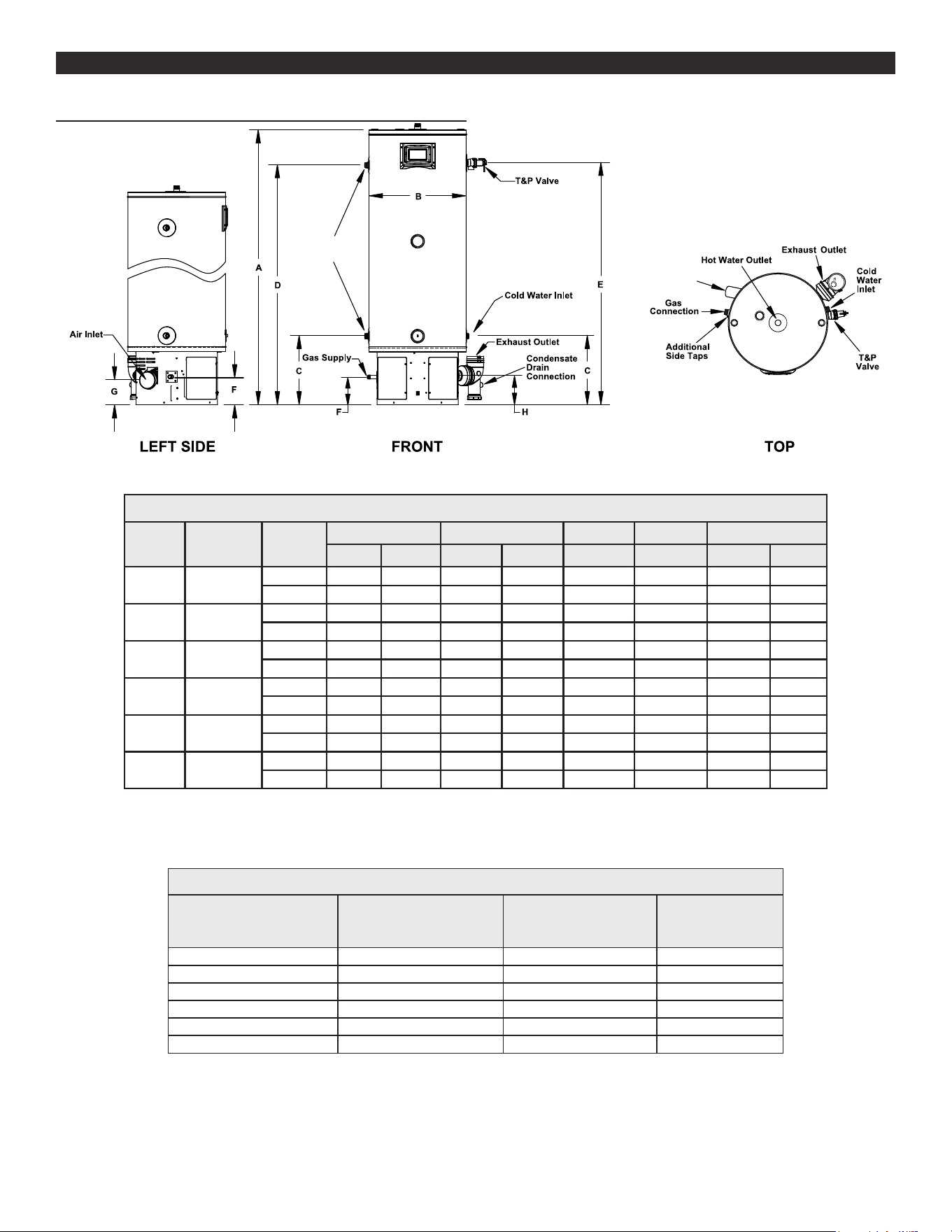
ROUGH IN DIMENSIONS: ALL MODELS
Additional
Side Taps
Air Inlet
Figure 1. Dimensions for All Models
Table 1. Rough-In-Dimension A
U.S.
Gallons
Input
(KBTU/HR) Units
Exterior Water Connections T&P Hot Gas Supply Air Inlet/Exhaust
A B C D E F G H
34 130
Inches 48-1/2 22 15-3/4 40-1/2 41 6-3/8 5-1/2 6-5/8
cm 123.19 55.88 40 102.87 104.14 16.19 13.97 16.82
34 150
Inches 48-1/2 22 15-3/4 40-1/2 41 6-3/8 5-1/2 6-5/8
cm 123.19 55.88 40 102.87 104.14 16.19 13.97 16.82
50 130
Inches 62-3/8 22 15-3/4 54-1/2 55 6-3/8 5-1/2 6-5/8
cm 165.7 55.88 40 138.43 139.7 16.19 13.97 16.82
50 150
Inches 63-3/4 22 15-3/4 55-3/4 56-1/4 6-3/8 5-1/2 6-5/8
cm 161.925 55.88 40 141.605 142.875 16.19 13.97 16.82
50 175
Inches 63-3/4 22 15-3/4 55-3/4 56-1/4 6-3/8 5-1/2 6-5/8
cm 161.925 55.88 40 141.605 142.875 16.19 13.97 16.82
50 199
Inches 63-3/4 22 15-3/4 55-3/4 56-1/4 6-3/8 5-1/2 6-5/8
cm 161.925 55.88 40 141.605 142.875 16.19 13.97 16.82
Top Outlet: 1” NPT
Side Inlet: 1” NPT
Gas Inlet: 1/2” NPT
Condensate drain outlet: 1/2” NPT
Table 2. Rough-In-Dimensions B
U.S. Gallons
Input
(KBTU/HR)
Vent
Diameter
(in.)
Approx Ship.
Weight
(lbs.)
34 130 2 OR 3 150
34 150 2 OR 3 150
50 130 2 OR 3 176
50 150 2 OR 3 180
50 175 3 180
50 199 3 180
10
DIMENSIONS AND CAPACITY DATADIMENSIONS AND CAPACITY DATA
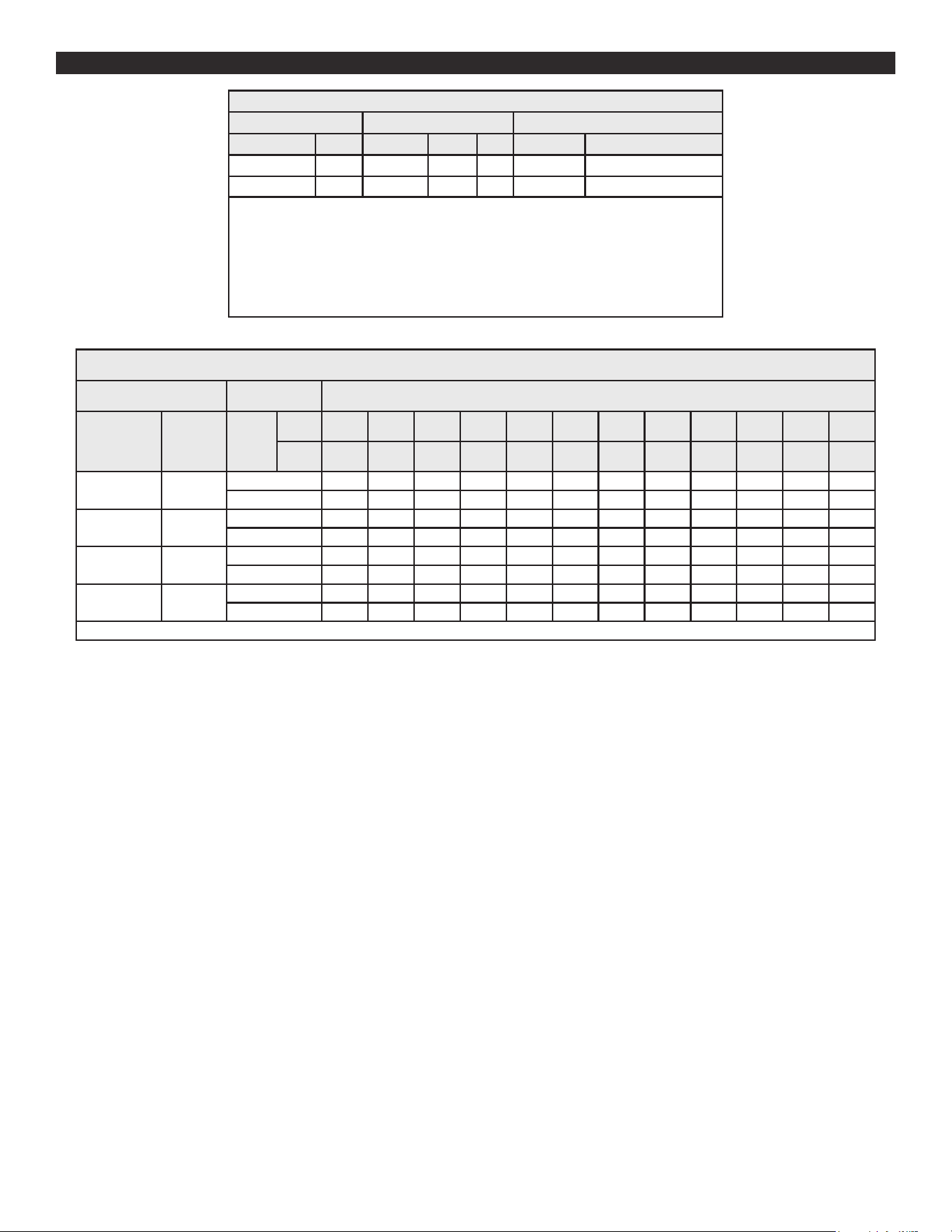
Table 3. Capacity, Gas and Electrical Characteristics
Approximate Capacity *Manifold Pressure Electrical Characteristics
U.S. Gals. Liters Gas Type “WC kPA Volts/Hz Amperes
34 129 Nat./LP 0 0 120/60 <7
50 189 Nat/LP 0 0 120/60 <7
* The manifold pressure is the factory setting and is not adjustable. A negative pressure will be
seen with just the blower running without the Gas Control Valve open.
All models - Maximum Supply Pressure: 14 inches W.C. (3.48kPa)
Minimum Supply Pressure for Natural Gas: 3.50” (.87kPa)
Minimum Supply Pressure for Propane Gas: 8.00” (1.99kPa)
Minimum pressure must be maintained under both load and no load (dynamic and static)
conditions.
Table 4. Recovery Capacities
Input Recovery Capacities
Rating
(Btu/hr)
Rating
(kW)
Temp.
Rise
F 30 40 50 60 70 80 90 100 110 120 130 140
C 17 22 28 33 39 44 50 56 61 67 72 78
130000 38.1
GPH 495 371 297 248 212 186 165 149 135 124 114 106
LPH 1875 1406 1125 937 803 703 625 562 511 469 433 402
150000 44.0
GPH 571 429 343 286 245 214 190 171 156 143 132 122
LPH 2163 1622 1298 1082 927 811 721 649 590 541 499 464
175000 51.3
GPH 667 500 400 333 286 250 222 200 182 167 154 143
LPH 2524 1893 1514 1262 1082 946 841 757 688 631 582 541
199000 58.3
GPH 758 569 455 379 325 284 253 227 207 190 175 162
LPH 2870 2152 1722 1435 1230 1076 957 861 783 717 662 615
Recovery capacity based on 95% thermal eciency.
11
* CAUTION HARNESS HAS 120 VAC. IN OPERATION.
** See Venting Installation (page 23) and Condensate Piping
for more information.
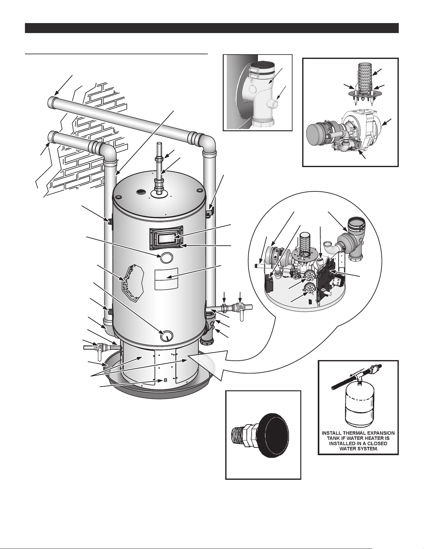
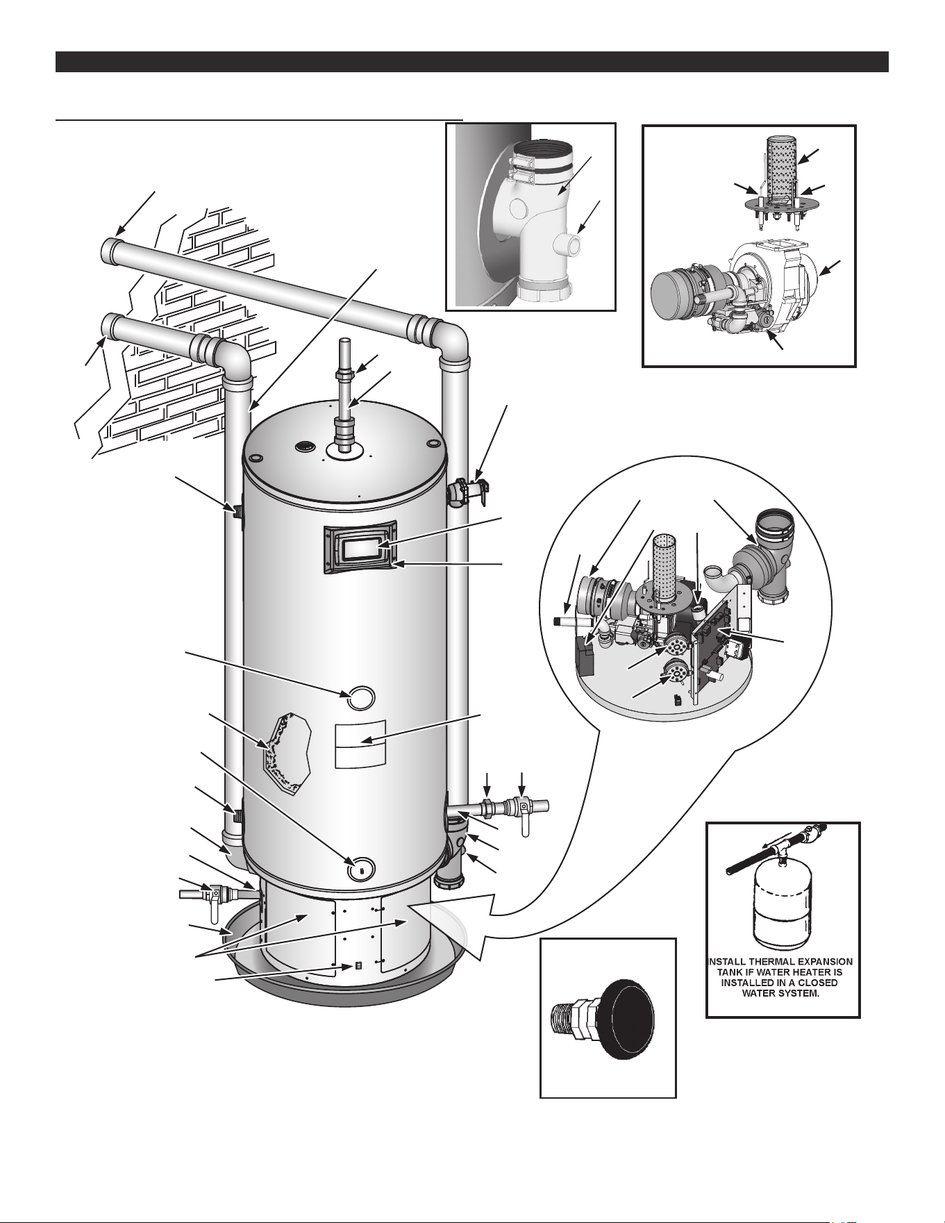
FEATURES AND COMPONENTSFEATURES AND COMPONENTS
34 GALLON UNIT
15
32
27
**33
29
32
24
31
26
20
19
**12
**11
**25
13
28
9
10
21, 22
17
17
18
14
16
This is a view of the area
at the bottom of
heater behind the
Access Doors.
1
30
11
15
2
3
23
**34
33
Figure 2. 34 Gallon Unit
8
4
6
7
5
VACUUM RELIEF
VALVE
*INSTALL PER
LOCAL CODES
**11
**12
12
* CAUTION HARNESS HAS 120 VAC. IN OPERATION.
** See Venting Installation (page 23) and Condensate Piping
for more information.
FEATURES AND COMPONENTS (CONT.)FEATURES AND COMPONENTS (CONT.)
50 GALLON UNIT
This is a view of the area
at the bottom of
heater behind the
Access Doors.
1
2
3
15
32
27
**33
29
32
24
26
20
19
**12
**11
**25
13
28
9
10
21, 22
17
18
16
30
11
15
23
33
**34
31
17
14
Figure 3. 50 Gallon Unit
8
4
6
7
5
VACUUM RELIEF
VALVE
*INSTALL PER
LOCAL CODES
**11
**12
13
FEATURES AND COMPONENTS (CONT.)FEATURES AND COMPONENTS (CONT.)
1: Control Assembly
2: Blocked Outlet Switch
3: Blocked Intake Switch
4: Blower Assembly
5: Burner Assembly
6: Flame Sensor
7: Igniter Assembly
8: Gas Control Valve Assembly
9: Display Board
10: Display Enclosure
** 11: Exhaust Elbow Assembly
** 12: Condensate Drain Outlet
13: Enable / Disable Switch
14: Hot Water Outlet
15: Gas Supply
16: Main Manual Gas Shuto Valve
17: Union
18: Inlet Water Shuto Valve
19: Cold Water Inlet
20: T & P Relief Valve
21: Rating Plate
22: Labels
23: Drain Valve
24. Upper Temperature Probe (ECO)
** 25: Exhaust Vent Terminal
26: Drain Pan
27: Insulation
28: Lower Temperature Probe
29: Access Door
30: Spark Module
31. Air Intake Pipe
32. Additional Side Taps
33. Intake Air Connection
**34. Intake Vent Terminal
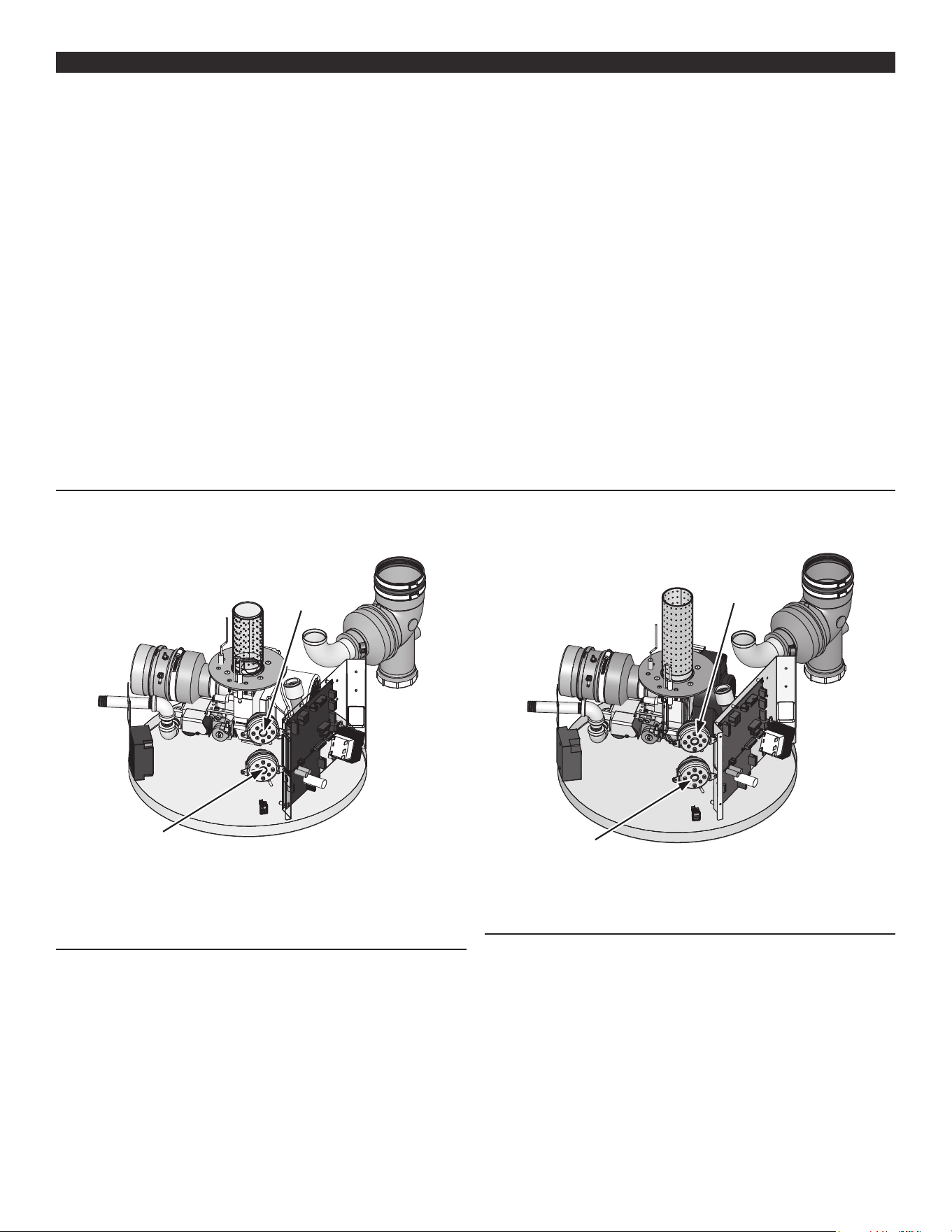
CONTROLS AND SWITCHES
This model is provided with two pressure switches. These switches are essential to the safe and proper operation of the unit. All switches
are wired in series. The controller is set up to shut the unit down whenever there is a failure of any of the switches. It is important to
understand the purpose of each switch.
Blocked Outlet
Switch
Blocked Intake
Switch
Figure 4. 34 Gallon Unit
BLOCKED OUTLET SWITCH
The Blocked Outlet Switch is set up to shut the unit o when a build-
up of positive pressure in the exhaust vent pipe occurs. This switch
is a positive pressure switch that requires an increase in pressure to
change the electrical contacts from normally closed to open. When
this switch prevents the unit from igniting, most likely the exhaust is
blocked by some means. Check to see if the condensate is allowed
to ow freely from the exhaust elbow and for obstructions in the
exhaust venting and exhaust vent terminal. Also verify that the vent
length does not exceed the maximum allowed as shown in Planning
The Vent System (page 25).
Blocked Outlet
Switch
Blocked Intake
Switch
Figure 5. 50 Gallon Unit
BLOCKED INTAKE SWITCH
The Blocked Intake Switch is set up to shut the unit o when a build-
up of negative pressure in the intake air pipe occurs. This switch
is a negative pressure switch that requires an increase in negative
pressure to change the electrical contacts from normally closed to
open. The switch is connected to the pressure tap on the PVC pipe
connected to the inlet of the blower. When this switch prevents the
unit from igniting, most likely the intake is blocked. Verify that the
integrated lter on the intake air connection, the intake air pipe, and
the intake air termination are free of obstructions that may prevent
air from entering the unit. Also Verify the intake air pipe length does
not exceed the maximum allowed in Planning the Planning The Vent
System (page 25).

14
WATER HEATING ENABLE/DISABLE SWITCH
Important: The Enable/Disable switch listed in this manual is NOT
an “on/o” switch and does not disconnect 120 volt
power to the CCB and other heater components.
When in the “Disabled” position the switch removes electrical power
from the gas control valve so that water heating is disabled. The
display, CCB, and other electrical components will still be energized
and the display will read “Water Heating Disabled”.
SPARK IGNITER
The Spark Igniter is a device that ignites the main burner by spark.
When high voltage is applied to the igniter, spark is generated to
ignite the main burner.
CONFIGURATION KEY
The conguration key is located inside the control box. It provides
for the ability of the heater to retain information collected over its
lifetime, even if the control board is replaced because of failure.
The conguration key should stay with the heater.
15
INSTALLATION CONSIDERATIONSINSTALLATION CONSIDERATIONS
LOCATING THE WATER HEATER
Property Damage Hazard
All water heaters eventually leak.
•
Do not install without adequate drainage.
•
CAUTION
Carefully choose a location for the new water heater. The placement
is a very important consideration for the safety of the occupants in
the building and for the most economical use of the water heater.
Whether replacing an existing water heater or installing the water
heater in a new location observe the following critical points:
1. The water heater must be located indoors.
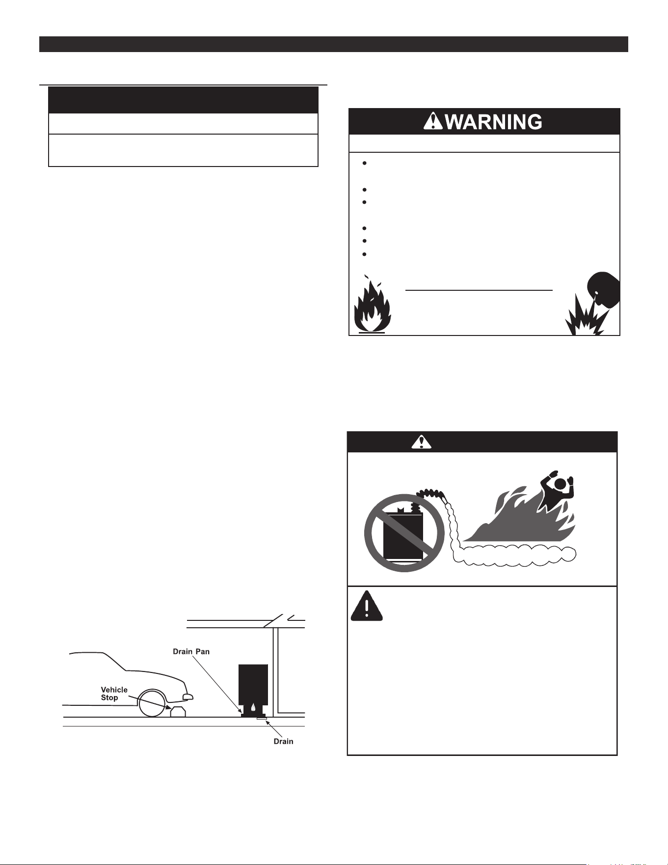
2. The water heater must not be located in an area where it will be
subject to freezing temperatures.
3. Locate the water heater so it is protected and not subject to
physical damage by a moving vehicle. In garage installation
avoid damage to your water heater by installing a vehicle stop as
shown in Figure 5. Check state and local codes for requirements
prior to installation.
4. Locate the water heater on a level surface.
5. Locate the water heater near a oor drain. The water heater
should be located in an area where leakage of the tank or
connections will not result in damage to the area adjacent to
the water heater or to lower oors of the structure. When such
locations cannot be avoided, it is recommended that a metal
drain pan, piped to adequate drain, be installed under the water
heater. Drain pan should be fabricated with sides at least 1-3/4”
deep with diameter at least 2” greater than diameter of heater.
Pan must not restrict combustion air ow.
6. Locate the water heater close to the point of major hot water
usage.
7. Locate the water heater close to a 120 VAC power supply. See
Power Supply (page 18) for requirements.
8. Locate the water heater where an adequate supply of fresh air
for combustion and ventilation can be obtained. See Combustion
Air And Ventilation (page 16).
9. Locate the water heater where the vent and intake air piping,
when installed, will remain within the maximum equivalent lengths
allowed. See Planning The Vent System (page 25).
Figure 6. Garage installation
10. Do not locate the water heater where noise (such as the
Combustion Blower) during normal operation will be objectionable
in adjacent areas.
11. Do not locate the water heater where the subsequent installation
of the vent (exhaust) or intake air terminations would be
objectionable due to noise at the termination(s). This includes
locations close to or across from windows and doors. See Venting
Installation (page 23).
Fire or Explosion Hazard
Read instruction manual before
installing, using or servicing
water heater.
Avoid all ignition sources if you smell gas.
Do not store or use gasoline or other flammable vapors and
liquids in the vicinity of this or any other appliance.
Use only the gas shown on the water heater rating label.
Keep ignition sources away from faucets after extended
periods of non-use.
Maintain required clearances to combustibles.
Do not expose water heater controls to excessive gas
pressure.
Do not locate water heater areas where ammable liquids (vapors)
are likely to be present or stored (garages, storage and utility areas,
etc.): Flammable liquids (such as gasoline, solvents, propane (LP or
butane, etc.) and other substances (such as adhesives, etc.) emit
ammable vapors which can be ignited by a gas water heater’s
ignition device or main burner. The resulting ashback and re can
cause death or serious burns to anyone in the area.
Flammable Vapors
FLAMMABLES
DANGER
Vapors from flamable
liquids may explode
and catch fire causing
death or sever burns.
Water heater has a main
burner and ignition device.
The ignition device:
1. Can come on at any time.
2. Will ignight flammable
vapors.
Do not use or store flammable
products, such as gasoline,
solvents, or adhesives in the
same room or area near the
water heater.
Keep flamable products:
1. Fare away from heater.
2. In approved containers.
3. Tightly closed and
4. Out of children’s reach
Vapors:
1. Cannot be seen.
2. Are Heavier than air.
3. Go a long way on the floor.
4. Can be carried from other
rooms to the ignition
device by air currents.
When the water heater is installed directly on carpeting, the water
heater shall be installed on a metal or wood panel extending beyond
the full width and depth of the water heater by at least 3″ (7.62 cm) in
any direction or, if the water heater is installed in an alcove or closet,
16
the entire oor shall be covered by the panel. The panel must be
strong enough to carry the weight of the heater when full of water.
Fire and Explosion Hazard
•
Improper use can result in fire or
explosion.
Read the instruction manual before
installing, using, or servicing the water
heater.
•
Maintain required clearances to
combustibles.
Minimum clearances from combustible materials are stated on
the data plate located on the front of the water heater. Standard
clearances are 0” (0 cm) at the sides and rear, 0” (0 cm) from the
front, and 0” (0 cm) from the top. If the clearances from combustible
material stated on the water heater differ from the standard
clearances, install the water heater according to the clearances
stated on the water heater.
Adequate clearance for inspection and service should be considered
before installation. A minimum of 24” (61 cm) of front clearance
and 4” (10.2 cm) on each side should be provided for access to
replaceable and/or serviceable parts such as thermostats, drain
valve, condensate drain, temperature-pressure relief valve, and the
vent connection (exhaust elbow).
Figure 6 may be used as a reference guide to locate the specic
clearance locations. When installing the water heater, consideration
must be given to proper location. The location selected should be
as close to the wall as practicable and as centralized with the water
piping system as possible.
CEILING
FRONT VIEW
0"
MIN.
0" MIN.
*4" MIN.
*For service access
LEFT
WALL
RIGHT
WALL
TOP VIEW
OF CLOSET
WITHOUT DOOR
WATER
HEATER
0" MIN.
0" MIN.
*24" MIN. (61 cm)
TOP VIEW
OF CLOSET
WITHOUT DOOR
WATER
HEATER
Figure 7. Minimum Clearance Locations
INSULATION BLANKETS
Do not obstruct water heater air intake.
Gas and carbon monoxide detectors
are available.
Install water heater in accordance with
the instruction manual.
Breathing carbon monoxide can cause brain damage or
death. Always read and understand instruction manual.
Breathing Hazard - Carbon Monoxide Gas
Insulation blankets are available to the general public for external
use on gas water heaters but are not necessary with these products.
The purpose of an insulation blanket is to reduce the standby heat
loss encountered with storage tank heaters. Your water heater
meets or exceeds the Energy Policy Act standards with respect
to insulation and standby loss requirements, making an insulation
blanket unnecessary.
Should you choose to apply an insulation blanket to this heater, you
should follow these instructions (For identication of components
mentioned below. See Figure 1 (page 9), Figure 2 (page 11),
Figure 3 (page 12), and Figure 4 (page 13). Failure to follow these
instructions can restrict the air ow required for proper combustion,
potentially resulting in re, asphyxiation, serious personal injury or
death.
• DO NOT cover the control system LCD on top of the water heater.
• DO NOT cover the outer door, thermostat or temperature-
pressure relief valve.
• DO NOT cover the instruction manual. Keep it on the side of the
water heater or nearby for future reference.
• DO obtain new warning and instruction labels from the
manufacturer for placement on the blanket directly over the
existing labels.
• DO inspect the insulation blanket frequently to make certain it
does not sag, thereby obstructing combustion air ow.
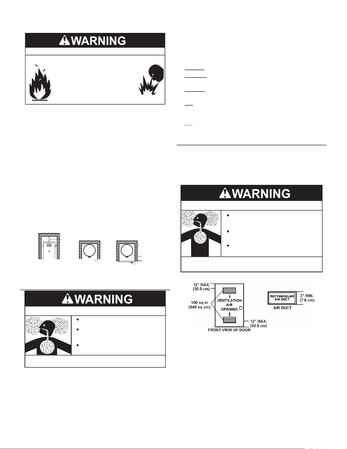
COMBUSTION AIR AND VENTILATION
A gas water heater cannot operate properly without the correct
amount of air for combustion. Never obstruct the ow of ventilation
air. If you have any doubts or questions at all, call your gas supplier.
Failure to provide the proper amount of combustion air can result in
a re or explosion and cause death, serious bodily injury, or property
damage.
Breathing Hazard - Carbon Monoxide Gas
Install water heater in accordance with
the Instruction Manual and CAN/C-
SA-B149.1.
To avoid injury, combustion and ventilation
air must be taken from outdoors.
Do not place chemical vapor emitting
products near water heater.
Breathing carbon monoxide can cause brain damage or
death. Always read and understand instruction manual.
Figure 8. Combustion Air and Ventilation
It is imperative that the water heater(s) be installed direct vent so
that all air for combustion and ventilation is taken from outdoors.
Propellants of aerosol sprays and volatile compounds, (cleaners,
chlorine based chemicals, refrigerants, etc.) in addition to being
highly ammable in many cases, will also react to form corrosive
acids when exposed to the combustion products of the water heater.
The results can be hazardous, and also cause product failure. Air
for combustion and ventilation must not come from a corrosive
atmosphere. Any failure due to corrosive elements in the atmosphere
is excluded from warranty coverage.

17
CORROSION AND WATER QUALITY
Water quality will vary from location to location and may contain
contaminates that may reduce the life or performance of the water
heater.
Contaminates which can reduce the life or performance of the water
heater if present in high quantities include those which contribute
to hardness (dissolved minerals such as sodium, calcium and
magnesium); plus chlorides and sulfates. Additionally, water that
is too acidic or basic (measured as pH) can reduce the life of the
water heater. Water treatment systems (such as water softeners for
hardness) should be used and maintained properly if the contaminate
levels exceed the following:
WARRANTY IS VOID IN APPLICATIONS WHICH EXCEED THE
WATER QUALITY REQUIREMENTS LISTED BELOW.
Total Hardness: 12 grains per gal. (205 mg/liter) max.
Chloride: 200 mg/liter max.
pH: 6.5-8.0
Alkalinity: 200 mg/liter max.
18
INSTALLATION REQUIREMENTSINSTALLATION REQUIREMENTS
GAS SUPPLY SYSTEMS
Fire and Explosion Hazard
Turn off gas lines during installation.
Contact a qualified installer or service
agency for installation and service.
Excessive gas pressure to gas valve can
cause serious injury or death.
Do not use water heater with any gas
other than the gas shown on the rating
label.
Low pressure building gas supply systems are dened as those
systems that cannot under any circumstances exceed 14” W.C.
(1/2 PSI Gauge). These systems do not require pressure regulation.
Measurements should be taken to insure that gas pressures are
stable and fall within the requirements stated on the water heater
rating plate. Readings should be taken with all gas burning equipment
o (static pressure) and with all gas burning equipment running at
maximum rate (dynamic pressure). The gas supply pressure must
be stable within 1.5” W.C. from static to dynamic pressure to provide
good performance. Pressure drops that exceed 1.5” W.C. may cause
rough starting, noisy combustion or nuisance outages. Increases or
spikes in static pressure during o cycles may cause failure to ignite
or in severe cases damage to water heater gas control valves. If
your low pressure system does NOT meet these requirements, the
installer is responsible for the corrections.
High pressure building supply systems use pressures that exceed
14” W.C. (1/2 PSI Gauge). These systems must use eld supplied
regulators to lower the gas pressure to less than 14” W.C. (1/2 PSI
Gauge). Water heaters require gas regulators that are properly
sized for the water heater input and deliver the rating plate specied
pressures. Gas supply systems where pressure exceeds 5 PSI often
require multiple regulators to achieve desired pressures. Systems in
excess of 5 PSI building pressure should be designed by gas delivery
professionals for best performance. Water heaters connected to gas
supply systems that exceed 14” W.C. (1/2 PSI Gauge) at any time
must be equipped with a gas supply regulator.
All models require a minimum gas supply pressure of 3.5” W.C.(0.87
kPa) for natural gas and 8.0” W.C. (1.99 kPa) for propane. The
minimum supply pressure is measured while gas is not owing
(static pressure) AND while gas is owing (dynamic pressure). The
supply pressure (static and dynamic) should never fall below 3.5”
W.C.(0.87 kPa) for natural gas or 8.0” W.C. (1.99 kPa) for propane.
The supply pressure should be measured with all gas red water
heaters connected to the common main ring at full capacity. If the
supply pressure drops more than 1.5” W.C. (0.37 kPa) as gas begins
to ow to the water heater then the supply gas system including the
gas line and/or the gas regulator may be restricted or undersized.
See Supply Gas Regulator (page 18) and Supply Gas Line Installation
(page 33). The gas control valve on all models has a maximum
gas supply pressure limit of 14” W.C.(3.48 kPa) The maximum supply
pressure is measured while gas is not owing (static pressure) AND
while gas is owing (dynamic pressure).
SUPPLY GAS REGULATOR
The maximum allowable gas supply pressure for this water heater
is 14 inches W.C. (3.5 kPa). Install a positive lock-up gas pressure
regulator in the gas supply line if inlet gas pressure can exceed 14
inches W.C. (3.5 kPa) at any time. Regulators must be sized/used
according to manufacturer’s specications.
If a positive lock-up regulator is required follow these instructions:
1. Positive lock-up gas pressure regulators must be rated at or above
the input Btu/hr rating of the water heater they supply.
2. Supply gas regulators shall have inlet and outlet connections not
less than the minimum supply gas line size for the water heater
they supply
3. Positive lock-up gas pressure regulator(s) should be installed no
closer than 3 feet (1 meter) and no farther than 8 feet (2.4 meters)
from the water heater’s inlet gas connection.
4. After installing the positive lock-up gas pressure regulator(s) an
initial nominal supply pressure setting of 7.0” W.C.(1.74 kPa) for
Natural Gas and 11.0” W.C. (2.74 kPa) for Propane (LP) while
the water heater is operating is recommended and will generally
provide good water heater operation. Some additional adjustment
may be required later to maintain a steady gas supply pressure.
5. When installing multiple water heaters in the same gas supply
system it is recommended that individual positive lock-up gas
pressure regulators be installed at each unit.
All gas piping must comply with local codes and ordinances or with
the current editions National Fuel Gas Code (ANSI Z223.1/ NFPA-54) or the
Natural Gas and Propane Installation Code (CAN/CSA B149.1) whichever
applies. Copper or brass tubing and ttings (except tin lined copper
tubing) shall not be used.
If the gas control valve is subjected to pressures exceeding 1/2 psi
(3.5 kPa), the damage to the gas control valve could result in a re
or explosion from leaking gas.
If the main gas line Shut-o serving all gas water heaters is used,
also turn o the gas at each water heater. Leave all gas appliances
shut o until the water heater installation is complete.
A gas line of sucient size must be run to the water heater. Consult
the current edition of National Fuel Gas Code ( Z223.1/NFPA 54) or the
Natural Gas and Propane Installation Code (CAN/CSA B149.1) and your gas
supplier concerning pipe size.
There must be:
• A readily accessible manual shut o valve in the gas supply line
serving the water heater, and
• A sediment trap ahead of the gas control valve to help prevent
dirt and foreign materials from entering the gas control valve.
• A ground joint union of proper size between the manual shut o
valve and gas control valve to permit servicing of the unit.
Be sure to check all the gas piping for leaks before lighting the water
heater. Use a soapy water solution, not a match or open ame. Rinse
o soapy solution and wipe dry.
POWER SUPPLY
The water heaters covered in this manual require a 120 VAC,
1Ø (single phase), 60Hz, 7 amp power supply and must also be
electrically grounded in accordance with local codes or, in the
absence of local codes, with the National Electrical Code, ANSI/NFPA 70
or the Canadian Electrical Code, CSA C22.1.
If any of the original wire as supplied with the water heater must
be replaced, it must be replaced with 105°C rated wiring or its
equivalent, except in the burner housing. In this case 200°C rated
wire must be used.
19
DEDICATED POWER WIRING AND BREAKERS
Dedicated power supply wires, ground wiring and dedicated circuit
breakers often prevent electrical line noise and should be considered
when installing the water heater.
Note: This water heater should not be connected to an electrical
supply with a ground fault circuit interrupter (GFCI) or arc
fault circuit interrupter (AFCI) with integral GFCI protection
as dened in NFPA70, CSA C22.1 and UL 943.
POWER FLUCTUATIONS AND ELECTRICAL NOISE
The water heater’s control system requires a source of stable
clean electricity for proper operation. Connecting the water heater
to a branch circuit that is subject to uctuations in voltage level or
electrical line noise such as EMI (electro magnetic interference) or
RFI (radio frequency interference) may cause erratic control system
operation and malfunction.
A high quality power supply lter/suppressor must be installed if the
above conditions exist. Call the technical support phone number for
more information.
Note: Malfunctions caused by the power supply and the costs to
install power supply lters are not covered under the limited
warranty.
MIXING VALVES
Water temperature over 125°F (52°C)
can cause severe burns instantly
resulting in severe injury or death.
Children, the elderly and the
physically or mentally disabled are at
highest risk for scald injury.
Feel water before bathing or
showering.
Temperature limiting devices such as
mixing valves must be installed
when required by codes and to
ensure safe temperatures at fixtures.
Water heated to a temperature which will satisfy clothes washing,
dish washing, and other sanitizing needs can scald and cause
permanent injury upon contact. Short repeated heating cycles caused
by small hot water uses can cause temperatures at the point of use to
exceed the water heater’s temperature setting by up to 20°F (11°C).
Some people are more likely to be permanently injured by hot water
than others. These include the elderly, children, the inrm and the
physically/mentally disabled. Table 5 shows the approximate time-
to-burn relationship for normal adult skin. If anyone using hot water
provided by the water heater being installed ts into one of these
groups or if there is a local code or state law requiring a certain
water temperature at the point of use, then special precautions
must be taken.
In addition to using the lowest possible temperature setting that
satises the demand of the application a Mixing Valve should be
installed at the water heater or at the hot water taps to further reduce
system water temperature. See Figure 9 (page 19) and Figure 56
through Figure 57 in Piping Diagrams (page 65).
Mixing valves are available at plumbing supply stores. Consult
a Qualified Installer or Service Agency. Follow mixing valve
manufacturer’s instructions for installation of the valves.
In all cases, the following burn table must be used.
Table 5. Burn Time at Various Temperatures
Water
Temperature
°F (°C)
Time for 1st Degree
Burn
(Less Severe Burns)
Time for Permanent
Burns
2nd & 3rd Degree
(Most Severe Burns)
110 (43.3) (normal shower temp.)
116 (46.7) (pain threshold)
116 (46.7) 35 minutes 45 minutes
122 (50) 1 minute 5 minutes
131 (55) 5 seconds 25 seconds
140 (60) 2 seconds 5 seconds
149 (65) 1 second 2 seconds
154 (67.8) instantaneous 1 second
(U.S. Government Memorandum, C.P.S.C., Peter L. Armstrong, Sept. 15, 1978)
CIRCULATION PUMPS
A circulating pump is used when a system requires a circulating
loop or there is a storage tank used in conjunction with the water
heater. The tank is provided with a 1” NPT recirculation loop return
connection. See Piping Diagrams (page 65) for the installation
location of circulating pumps.
See Circulation Pump Wiring Diagrams (page 65) for electrical
hookup information. Install in accordance with the current edition
of the National Electrical Code, NFPA 70 or the Canadian Electrical Code,
CSA C22.1.
Stainless Steel circulating pumps are recommended for use with
commercial water heaters.
See the circulating pump manufacturer’s instructions for its operation,
lubrication and maintenance instructions.
DISHWASHING MACHINES
All dishwashing machines meeting the National Sanitation
Foundation requirements are designed to operate with water ow
pressures between 15 and 25 pounds per square inch (103 kPa and
173 kPa). Flow pressures above 25 pounds per square inch (173
kPa), or below 15 pounds per square inch (103 kPa), will result in
improperly sanitized dishes. Where pressures are high, a water
pressure reducing or ow regulating control valve should be used
in the 180°F (82°C) line to the dishwashing machine and should be
adjusted to deliver water pressure between these limits. See Figure 9.
HOT WATER
OUTLET
TO TANK
INLET
CHECK
VALVE
MIXING
VALVE
COLD
WATER
INLET
TEMPERED WATER
OUTLET
12” TO 15”
(30-38 cm)
CHECK
VALVE
Figure 9. Mixing Valve
The National Sanitation Foundation also recommends circulation of
180°F (82°C) water. The circulation should be just enough to provide
180°F (82°C) water at the point of take-o to dishwashing machine.
Adjust ow by throttling a full port ball valve installed in the circulating
line on the outlet side of the pump. Never throttle ow on the suction
side of a pump.
Note: To comply with NSF Standard 5 installation requirements the
bottom of the water heater must be sealed to the oor with a
silicone based sealant or elevated 6 inches above the oor.
SPACE HEATING AND POTABLE WATER SYSTEM
Your water heater is equipped with additional side taps for use in
space heating applications. See Features and Components (page 11)
20
for locations. If this water heater is to be used to supply both space
heating and potable (drinking) water, the instructions listed below
must be followed:
• Be sure to follow the manual(s) shipped with the air handler or
other type heating system.
• This water heater cannot be used in space heating applications
only.
• This water heater is not to be used as a replacement for an
existing boiler installation.
• Do not use with piping that has been treated with chromates,
boiler seal or other chemicals and do not add any chemicals to
the water heater piping
• If the space heating system requires water temperatures in
excess of 120°F, a mixing valve must be installed per the
manufacturer’s instructions in the potable hot water supply to limit
the risk of scald injury. See Mixing Valves (page 19).
• Pumps, valves, piping and ttings must be compatible with
potable water.
• A properly installed ow control valve is required to prevent
thermosiphoning. Thermosiphoning is the result of a continuous
ow of water through the air handler circuit during the o cycle.
Weeping (blow o) of the temperature-pressure relief valve (T &
P relief valve) or higher than normal water temperatures are the
rst signs of thermosiphoning.
• The hot water line from the water heater should be vertical past
any mixing valve or supply line to the heating system to remove
air bubbles from the system. Do not connect the water heater
to any system or components previously used with non-potable
water heating appliances when used to supply potable water.
STORAGE TANK INSTALLATION
When installing the water heater with a storage tank. See Figure 58
(page 66) for suggestions.
Note: If tank temperature is set above 120°F and water is supplied
for domestic use (hand washing, showering, etc.) a mixing
valve should be installed in the hot water line to domestic
xtures. Installation must conform to local code requirements.
If a check valve is installed in the cold water supply line, an
expansion tank must be installed between the check valve
and the water heater’s cold water inlet. Set storage tank
temperature ve degrees lower than the water heater’s
temperature setting. Using the plug valve, adjust the ow in
the recirculating line to ve gallons per minute.
SOLAR INSTALLATION
If this water heater is used as a solar storage heater or as a backup
for the solar system, the water supply temperatures to the water
heater tank may be in excess of 120°F (48.9°C). A mixing valve must
be installed in the water supply line to limit the supply temperature
to 120°F (48.9°C).
Note: Solar water heating systems can often supply water with
temperatures exceeding 180°F (82.2°C) and may result in
water heater malfunction.
CLOSED WATER SYSTEMS
Water supply systems may, because of code requirements or such
conditions as high line pressure, among others, have installed
devices such as pressure reducing valves, check valves, and back
ow preventers. Devices such as these cause the water system to
be a closed system.
THERMAL EXPANSION
As water is heated, it expands (thermal expansion). In a closed
system the volume of water will grow when it is heated. As the
volume of water grows there will be a corresponding increase in
water pressure due to thermal expansion. Thermal expansion can
cause premature tank failure (leakage). This type of failure is not
covered under the limited warranty. Thermal expansion can also
cause intermittent temperature-pressure relief valve operation:
water discharged from the valve due to excessive pressure build
up. This condition is not covered under the limited warranty. The
temperature-pressure relief valve is not intended for the constant
relief of thermal expansion.
A properly sized thermal expansion tank should be installed on all
closed systems to control the harmful eects of thermal expansion.
Contact a local plumbing service agency to have a thermal expansion
tank installed.
Property Damage Hazard
● Avoid water heater damage.
● Install thermal expansion tank if necessary.
● Do not apply heat to cold water inlet.
● Contact qualified installer or service agency.
CAUTION
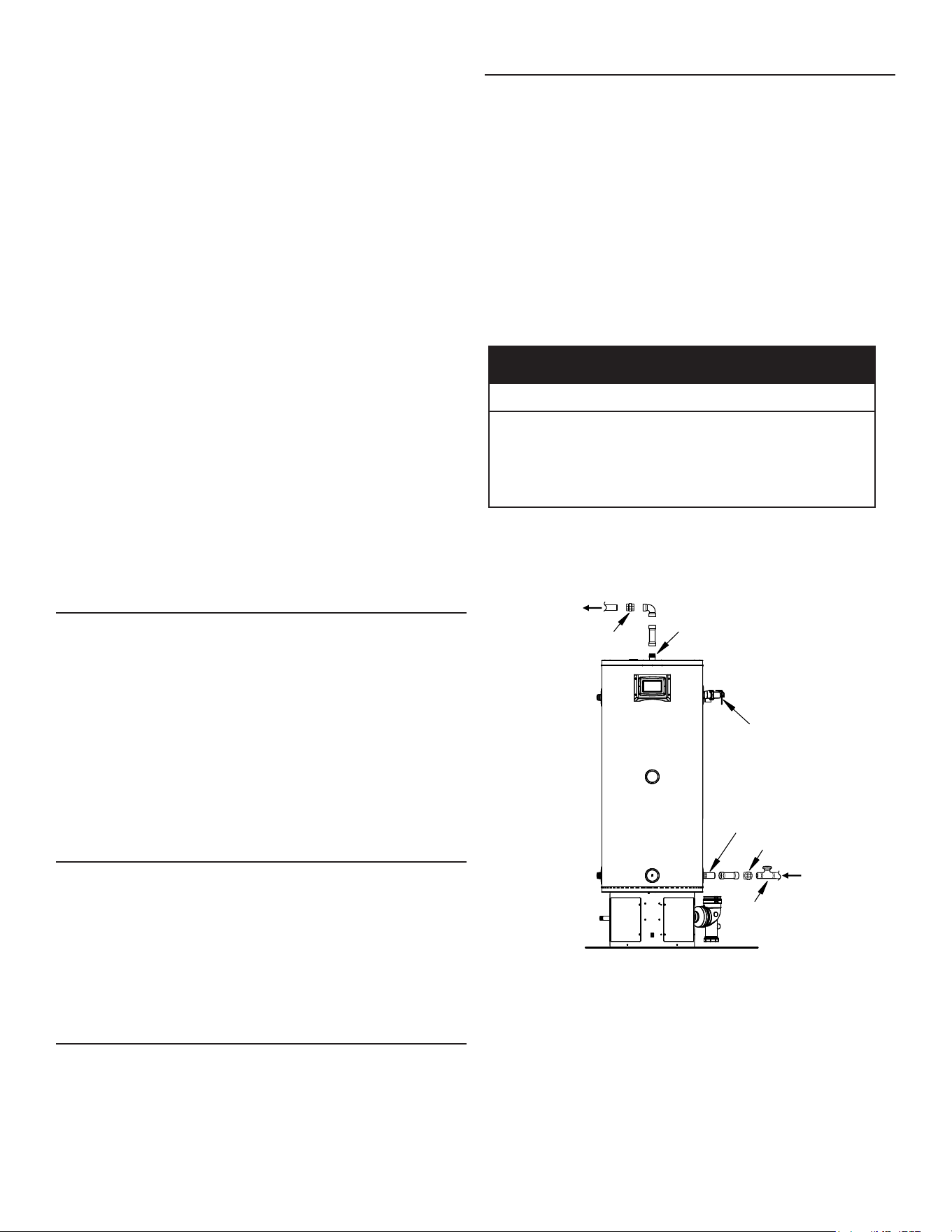
Note: To protect against untimely corrosion of hot and cold water
ttings, it is strongly recommended that di-electric unions or
couplings be installed on this water heater when connected
to copper pipe. See Figure 10.
Sweat
Fittings
Sweat
Fittings
Temperature -
Pressure
Relief Valve
Union
Union
Cold
Water
Inlet
Shutoff
Valve
Hot
Water
Outlet
Figure 10. Typical Water Heater Installation
Figure 10 also shows the typical attachment of the water piping to the
water heater. The water heater is equipped with 1” NPT connections
for all models.
Note: If using copper tubing, solder tubing to an adapter before
attaching the adapter to the water heater connections. Do not
solder the water lines directly to the water heater connections.
It will damage the tank, T & P Valve and Pipe Insulation (if
supplied).
Fit pipe insulation over the incoming cold water line and the hot
water line. Make sure that the insulation is against the top cover of
21
the heater. Fit T & P valve insulation over valve. Make sure that the
insulation does not interfere with the lever of the T & P valve.
Secure all insulation using tape.
TEMPERATURE-PRESSURE RELIEF VALVE
Explosion Hazard
Temperature-Pressure Relief Valve
must comply with ANSI Z21.22-
CSA 4.4 and ASME code.
Properly sized temperature-
pressure relief valve must be
installed in opening provided.
Can result in overheating and
excessive tank pressure.
Can cause serious injury or death.
This water heater is provided with a properly rated/sized and certied
combination Temperature-Pressure Relief Valve (T&P relief valve) by
the manufacturer. The valve is certied by a nationally recognized
testing laboratory that maintains periodic inspection of production of
listed equipment of materials as meeting the requirements for Relief
Valves for Hot Water Supply Systems, ANSI Z21.22 • CSA 4.4, and the code
requirements of ASME.
If replaced, the new T&P valve must meet the requirements of local
codes, but not less than a combination Temperature-Pressure Relief
Valve rated/sized and certied as indicated in the previous paragraph.
The new valve must be marked with a maximum set pressure not to
exceed the marked hydrostatic working pressure of the water heater
(150 psi = 1,035 kPa) and a discharge capacity not less than the
water heater Btu/hr or kW input rate as shown on the water heater’s
model rating plate.
Note: In addition to the factory installed Temperature-Pressure
Relief Valve on the water heater, each remote storage tank
that may be installed and piped to a water heating appliance
must also have its own properly sized, rated and approved
Temperature-Pressure Relief Valve installed.
Explosion Hazard
Temperature-Pressure Relief Valve
must comply with ANSI Z21.22-
CSA 4.4 and ASME code.
Properly sized temperature-
pressure relief valve must be
installed in opening provided.
Can result in overheating and
excessive tank pressure.
Can cause serious injury or death.
For safe operation of the water heater, the Temperature-Pressure
Relief Valve must not be removed from its designated opening
nor plugged. The Temperature-Pressure Relief Valve must be
installed directly into the tting of the water heater designed for the
Temperature-Pressure Relief Valve. Install discharge piping so that
any discharge will exit the pipe within 6 inches (15.2 cm) above an
adequate oor drain, or external to the building. In cold climates it is
recommended that it be terminated at an adequate drain inside the
building. Be certain that no contact is made with any live electrical
part. The discharge opening must not be blocked or reduced in size
under any circumstances. Excessive length, over 30 feet (9.14 m),
or use of more than four elbows can cause restriction and reduce
the discharge capacity of the valve.
No valve or other obstruction is to be placed between the
Temperature-Pressure Relief Valve and the tank. Do not connect
discharge piping directly to the drain unless a 6” (15.2 cm) air gap is
provided. To prevent bodily injury, hazard to life, or property damage,
the temperature-pressure relief valve must be allowed to discharge
water in adequate quantities should circumstances demand. If the
discharge pipe is not connected to a drain or other suitable means,
the water ow may cause property damage.
Water Damage Hazard
Temperature-Pressure Relief Valve discharge
pipe must terminate at adequate drain.
•
CAUTION
T&P VALVE DISCHARGE PIPE REQUIREMENTS:
• Shall not be smaller in size than the outlet pipe size of the valve,
or have any reducing couplings or other restrictions.
• Shall not be plugged or blocked.
• Shall not be exposed to freezing temperatures.
• Shall be of material listed for hot water distribution.
• Shall be installed so as to allow complete drainage of both the
Temperature-Pressure Relief Valve and the discharge pipe.
• Must terminate a maximum of six inches (15.2 cm) above a
oor drain or external to the building. In cold climates, it is
recommended that the discharge pipe be terminated at an
adequate drain inside the building.
• Shall not have any valve or other obstruction between the
temperature-pressure relief valve and the drain.
Burn hazard.
Hot water discharge.
Keep clear of Temperature-
Pressure Relief Valve
discharge outlet.
The Temperature-Pressure Relief Valve must be manually operated
at least twice a year. Caution should be taken to ensure that (1) no
one is in front of or around the outlet of the Temperature-Pressure
Relief Valve discharge line, and (2) the water manually discharged
will not cause any bodily injury or property damage because the
water may be extremely hot. If after manually operating the valve, it
fails to completely reset and continues to release water, immediately
close the cold water inlet to the water heater, follow the draining
instructions in this manual, and replace the Temperature-Pressure
Relief Valve with a properly rated/sized new one.
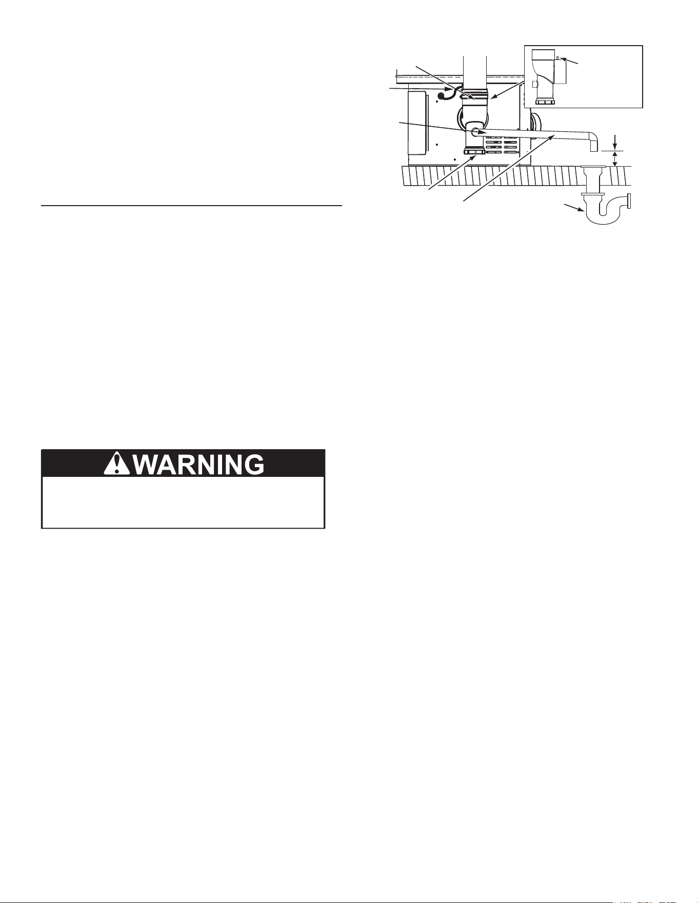
22
Note: The purpose of a Temperature-Pressure Relief Valve is to
prevent excessive temperatures and pressures in the storage
tank. The T&P valve is not intended for the constant relief of
thermal expansion. A properly sized thermal expansion tank
must be installed on all closed systems to control thermal
expansion. See Closed Water Systems and Thermal Expansion
(page 20).
If you do not understand these instructions or have any questions
regarding the Temperature-Pressure Relief Valve call the toll
free number listed on the back cover of this manual for technical
assistance.
CONDENSATE DRAIN
The water heaters covered in this manual are condensing water
heaters and require a building drain to be located in close proximity
to allow the condensate to drain safely.
Condensate drains from the water heater at the exhaust elbow
located at the bottom. The eld installed condensate drain line
must not be elevated above the condensate drain connection on
the condensate trap. See Figure 11. If the condensate does not drain
properly it will build up in the exhaust (vent) elbow. This will restrict the
ow of ue gases and cause the Blocked Exhaust pressure switch to
open its contacts. The control system monitors all pressure switches,
if the Blocked Exhaust Switch contacts are open the control system
will lock out and disable heating operation. The “Blocked Exhaust”
Fault message will be displayed on the control system’s LCD.
The Condensate Cleanout Cap must be on and tight when unit is
in operation.
Note: If the “Blocked Exhaust “ Fault message is ever displayed on
the control system LCD, check the condensate drain rst and
ensure it is not blocked.
OLD TRAP PIPING IS NOT COMPATIBLE WITH NEW
TRAP PIPING.
Building
Drain
Condensate
Cleanout Cap
Condensate Drain
Line - Field Installed
Condensate
Drain Line
Connection
Drain Line To Terminate No
More Than 6 Inches (15.2
cm)
Above Drain
Exhaust (Vent)
Elbow
This Side View
Of Exhaust
Elbow And
Arrow Indicate
The Location Of
The Pressure
Port
Pressure
Switch
Hose
Figure 11. Condensate Drain Conguration
DO NOT remove the factory installed exhaust/condensate elbow
for any reason. See Figure 11. The water heater’s vent pipe is under
a slight positive pressure while unit is in operation. The water trap
inside of the exhaust/condensate elbow prevents ue gases from
escaping into the installed space.
Do not install any external condensate trap. The exhaust elbow
assembly has an internal condensate trap.
Installation must conform with these instructions and local building
codes.
Field supplied materials required for installation include:
• Approved PVC cement and PVC primer.
• 1/2 inch PVC pipe - minimum length to equal the distance
between the water heater and a suitable building drain.
• 1/2 inch PVC fittings (elbows, couplings, and adapters)
necessary to install a condensate drain line between the Exhaust/
Condensate Elbow Assembly and a suitable building drain.
• Floor mounted standos to brace the drain line.
NOTES:
The condensate drains from the water heater’s covered by this
instruction have pH levels between 4.3 and 5.0. Install a commercially
available neutralizing kit if required by local codes. Lower pH levels
are acidic.
1. Do not connect a metal condensate drain line, such as copper
pipe, to the water heater for this reason.
2. The eld installed condensate drain line must not be less than
1/2 inch PVC in size.
3. DO NOT remove, modify or alter the factory condensate trap.
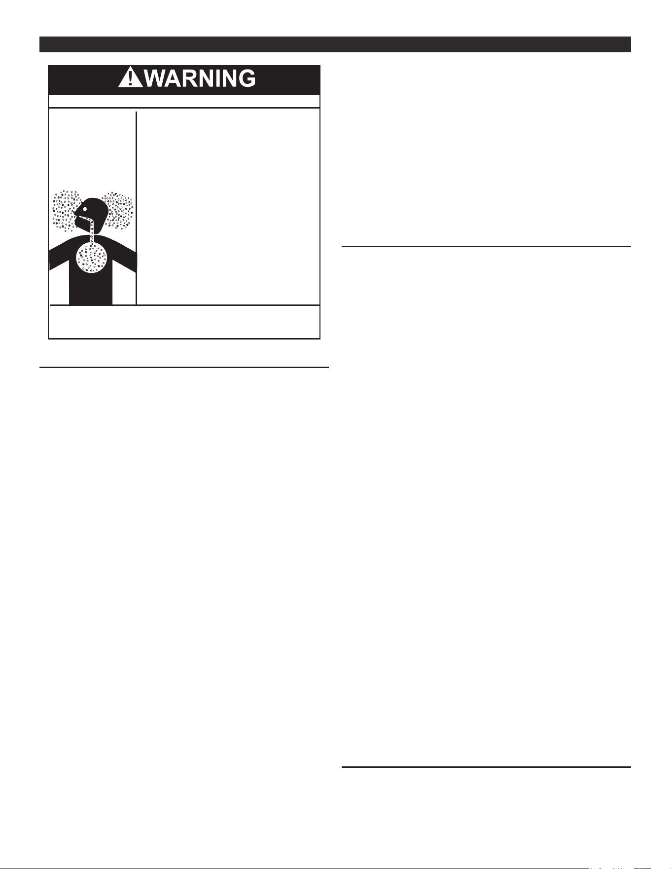
23
VENTING INSTALLATIONVENTING INSTALLATION
Breathing Hazard - Carbon Monoxide Gas
•
Install vent system in accordance with codes.
•
Do not operate water heater if any part has been
exposed to flooding or water damage.
•
Do not operate if soot buildup is present.
•
Never operate the heater unless it is vented to
the outdoors and has and has adequate air
supply to avoid risks of improper operation,
fire, explosion, or asphyxiation.
•
Do not obstruct water heater air intake with
insulating jacket.
•
Do not place chemical vapor emitting products
near water heater.
•
Analyze the entire vent system to make sure
that condensate will not become trapped in a
section of vent pipe and therefore reduce the open
cross sectional area of the vent.
•
Gas and carbon monoxide detectors are available.
Breathing carbon monoxide can cause brain damage or
death. Always read and understand instruction manual.
VENT INSTALLATION CONSIDERATIONS
This water heater has a direct vent system in which all air for
combustion is taken from the outside atmosphere and all combustion
products are discharged to the outdoors.
This water heater must be properly vented for removal of exhaust
gases to the outside atmosphere. Correct Installation of the vent
pipe system is mandatory for the safe and ecient operation of this
water heater and is an important factor in the life of the unit.
Vent pipe installation must be performed in accordance with state
and local codes, or in the absence of such, the National Fuel Gas Code,
NFPA 54, ANSI Z223.1-current edition. Canadian installations must be
performed in accordance with CAN/CSA-B149.1-current edition.
Either 2 inch or 3 inch pipe may be used on the vent termination
for 130,000 & 150,000 Btu/hr models. When concentric venting
130,000 & 150,000 Btu/hr, use only 2 inch concentric vent on the
vent termination. When concentric venting 130,000 & 150,000 Btu/
hr models, 3 inch pipe must be reduced to 2 inch concentric vent at
the termination. Use only 3 inch pipe or 3 inch concentric vent on
the vent termination for 175,000 & 199,000 Btu/hr models.
When replacing an existing water heater, it is recommended
that the venting system be reviewed for compliance with the
requirements contained in this instruction manual. If the venting is
not in compliance, it is recommended that the appropriate changes
be made to bring it into compliance. Never operate the water heater
unless it is vented to the outdoors.
Note: It is important that the factory-installed air inlet lter be
inspected periodically and cleaned if necessary. See Integrated
Filter Preventative Maintenance (page 59).
Note: If vent system is not in compliance with the current installation
manual, the manufacturer reserves the right to evaluate
installation prior to granting any warranty on service claims.
Important: Check to make sure the vent pipe is not blocked in
any way.
Note: Do not common vent this water heater with any other
appliance. Do not install in the same chase or chimney with
a metal or high-temperature plastic from another gas or fuel
burning appliance.
In cold climates any water vapor remaining in the ue gases will
condense into a cloud of vapor at the point where the vent system
exits the building. Special consideration is recommended, before
locating the vent termination near walkways, windows and building
entrances.
Direct venting into dead spaces such as alleys, atriums, and inside
corners can cause recirculation of ue gases. Recirculation of ue
gases will cause sooting, and icing of the combustion air intake
during severe cold weather. To prevent the recirculation of ue gases,
maintain as much distance as possible between the combustion
air intake and the exhaust vent terminal. Refer to Horizontal Vent
Terminal Installation (page 27) and Vertical Vent Terminal Installation
(page 27).
GENERAL VENTING INSTRUCTIONS
The following guidelines should be followed when installing the air
inlet and exhaust outlet piping:
• Venting should be as direct as possible with a minimum number
of pipe ttings.
• Vent diameter must not be reduced unless specically noted in
the installation instructions.
• All 2” horizontal inlet vent piping must be sloped downward 1/4
inch per foot (3” Piping must slope downward 1/8” per foot) toward
the water heater so that moisture in the inlet air will exit through
the air intake moisture drain trap.
• All 2” horizontal exhaust vent piping must be sloped upward 1/4
inch per foot (3” Piping must slope upward at 1/8” per foot) so
that condensate will run back to the heater and exit through the
condensate trap.
• Support all horizontal pipe runs every four feet and and all vertical
pipe runs every six feet or according to local codes.
• An air intake lter is included with the unit and must be installed
according to the installation instructions supplied with the lter.
• It is important to select the proper pipe cement for the type
of plastic pipe being used. All joints in the vent system piping
(except Polypropylene vent systems) must be properly cemented.
Polypropylene vent systems do not use cement to connect the
pipe and elbow sections but use a push together gasket seal
method. Do not attempt to connect Polypropylene with sealant
cement.
• Piping must be sized and cut before cementing. Cut the pipe
end square and remove all ragged edges and burrs. Make sure
the inside of the pipe is clean and free of cuttings and loose dirt.
Chamfer the end and apply primer to the tting and pipe. Apply
a moderate even coat of pipe cement inside the tting. Apply
a liberal amount of cement to the outside of the pipe to socket
depth. Assemble the parts quickly while cement is still wet. Twist
the pipe 1/4 turn during insertion and hold for 30 seconds.
• All pipe, ttings, pipe cement, primers and procedures must
conform to American National Standard Institute and American Society
for Testing and Materials (ANSI/ASTM) standards in the United States.
This water heater has been design certied by the Canadian
Standards Association for use with the specied (CSA) listed plastic
vent pipe.
APPROVED VENT/INTAKE MATERIAL
Approved vent and intake air pipe materials that may be used in
the United States:
PVC pipe materials:
• DWV ASTM-D2665 or CSA B181.2
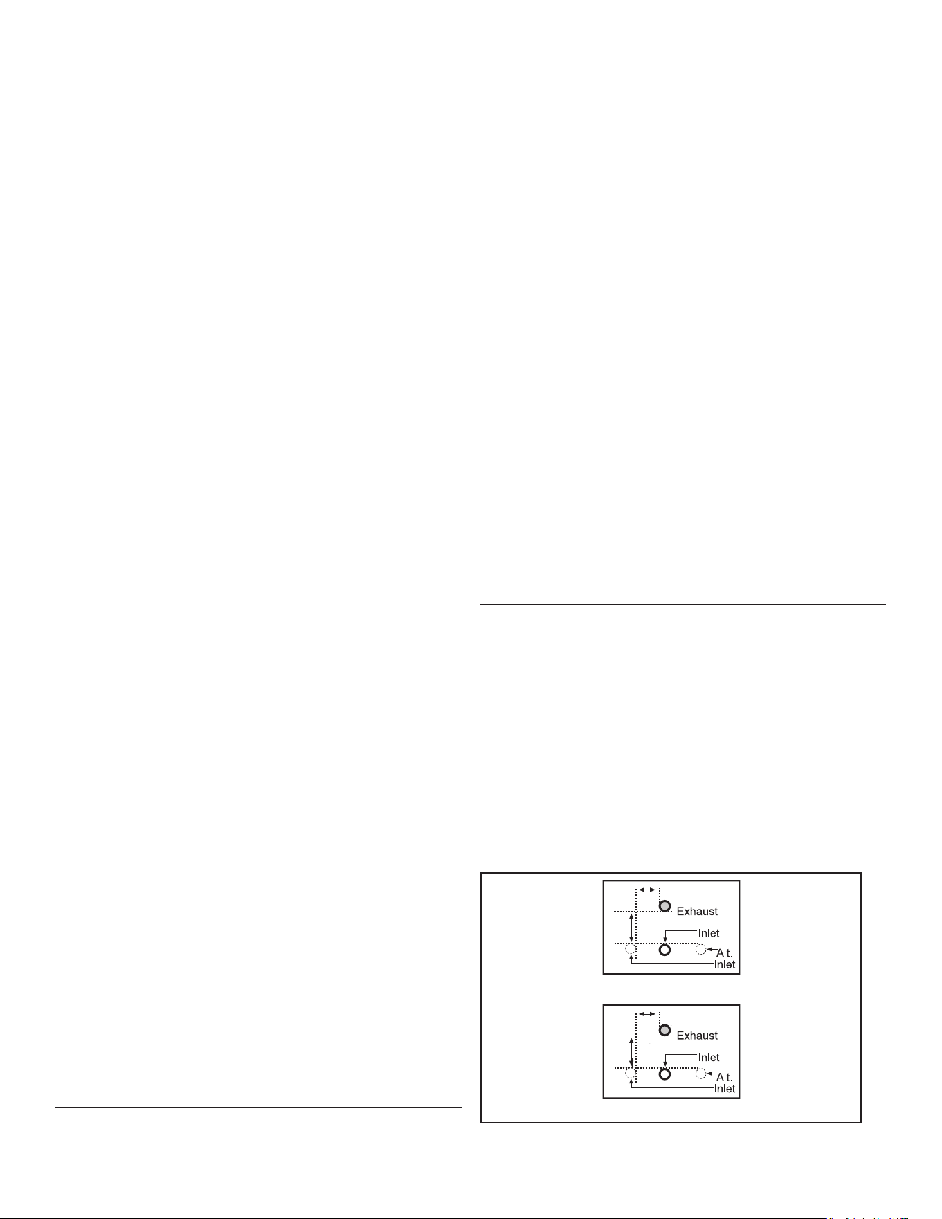
24
• Schedule 40, 80, 120 ASTM-D1785 or CSA B137.3
• SDR Series ASTM-2241 or CSA B137.3
CPVC pipe materials:
• CPVC 41 ASTM-D2846 or CSA B137.6
• Schedule 40, 80 ASTM-F441 or CSA B137.6
• SDR Series ASTM-F442
Polypropylene - See Polypropylene Installations.
• M & G Duravent PolyPro vent system
• Centrotherm InnoFlue vent system
Approved vent pipe materials that must be used in Canada:
• ULC S636 PVC / CPVC
• ULC S636 Polypropylene - See Polypropylene Installations.
Approved intake air pipe materials that must be used in Canada:
PVC pipe materials:
• DWV ASTM-D2665 or CSA B181.2
• Schedule 40, 80, 120 ASTM-D1785 or CSA B137.3
• SDR Series ASTM-D2241 or CSA B137.3
CPVC pipe materials:
• CPVC 41 ASTM-D2846 or CSA B137.6
• Schedule 40, 80 ASTM-F441 or CSA B137.6
• SDR Series ASTM-F442
Polypropylene - See Polypropylene Installations.
• M & G Duravent PolyPro vent system
• Centrotherm InnoFlue vent system
Where applicable, the installation of the venting system should
be done in accordance with the venting system manufacturer’s
instructions.
Note: The use of cellular core PVC (ASTM F891), cellular core
CPVC, or Radel
®
(polyphenolsulfone) in non-metallic venting
systems is prohibited. Covering non-metallic vent pipe and
ttings with thermal insulation is prohibited. If the water heater
is being installed as a replacement for an existing power
vented heater in pre-existing venting, a thorough inspection
of existing venting system must be performed prior to any
installation work. Verify that correct material as detailed
above has been used, and that the minimum or maximum
vent lengths and terminal location as detailed in this manual
have been met. Carefully inspect the entire venting system
for any signs of cracks or fractures, particularly at joints
between elbows and other ttings and straight runs of vent
pipe. Check system for signs of sagging or other stresses in
joints as a result of misalignment of any components in the
system. If any of these conditions are found, they must be
corrected in accordance with the venting instructions in this
manual before completing installation and putting the water
heater into service.
Note: For water heaters in locations with high ambient temperatures
above 100°F (38°C) it is recommended that CPVC or
Polypropylene pipe and ttings be used.
Note: Use only solid (not foam core) piping. Plastic pipe and ttings
are available through most plumbing suppliers. Always check
the marking on the pipe to make sure you are using the
correct material.
POLYPROPYLENE INSTALLATIONS
The water heater has been approved to be installed with
Polypropylene vent material as shown in Table 6 and Table 7 (page
25). The approved application of single wall, non-flexible,
non-concentric Polypropylene vent material is offered by two
specic manufacturers (Centrotherm ECO Systems and DuraVent
Polypropylene). These listed products must be installed by following
the vent manufacturer’s instructions. See Table 8 and Table 9 (page
25) to determine the maximum pipe length and number of elbows
that can be used.
Insulation should not be used on Polypropylene venting materials.
The use of insulation will cause increased vent wall temperatures,
which could result in vent pipe failure.
Use only the adapters and vent system listed in Table 6 and Table
7 (page 25). DO NOT mix vent systems of different types or
manufacturers. Failure to comply could result in severe personal
injury, death, or substantial property damage.
Installations must comply with applicable national, state, and local
codes. For Canadian installation, Polypropylene vent must be listed
as a ULC-S636 approved system. If Polypropylene vent is not required
by your local code, you may use either PVC or CPVC pipes for your
water heater that allows non-metallic venting material installations.
Polypropylene vent systems do not use cement to connect the pipe
and elbow sections but use a push together gasket seal method.
Do not attempt to connect Polypropylene with sealant cement. All
vent connections MUST be secured by the vent manufacturer’s joint
connector. The installer must use a specic vent starter adapter at
the ue connection. The adapter is supplied by the vent manufacturer
to adapt to its vent system.
In order to be in full compliance with UL 1738 or ULC-S636 and to meet
the requirements of the water heater manufacturer, you must use
the metal joint connector rings, available from the Polypropylene
vent manufacturer, to stien the joints of 2”, and 3” diameter pipes.
VENT PIPE INSTALLATION
The rst step is to determine where the inlet and exhaust vent pipes
will terminate. The combustion air inlet and exhaust outlet piping
and terminations may be installed in one of the following termination
types:
1. Standard Horizontal (2 Pipe) - See Figure 26 (page 30).
2. Alternate Horizontal (2 Pipe) - See Figure 21 (page 27).
3. Vertical (2 Pipe) - See Figure 22 (page 28), Figure 23 (page
28), & Figure 26 (page 30).
4. Concentric Vent Through the Wall - See Figure 31 (page 31).
5. Concentric Vent Through the Roof - See Figure 30 (page 31).
When venting one water heater, locate the inlet and exhaust
terminations according to Figure 12 (page 24). When installing
more than one water heater. See Venting Multiple Units (page 31).
4"
Max.
3" Max.
5"
Max.
4" Max.
Termination Dimensions: 2" Pipe
Termination Dimensions: 3" Pipe
Figure 12. Two- and Three-Inch Pipe Termination Dimensions

25
The vent system must terminate so that proper clearances are
maintained as cited in local codes or the current edition of the National
Fuel Gas Code, ANSI Z223.1 or the Natural Gas and Propane Installation
Code, CAN/CSA-B149.1. See Figure 25 (page 30).
Instructions on proper installation through a sidewall are provided in
Figure 19 (page 27) and Figure 20 (page 27). Plan the vent system
layout so that proper clearances are maintained from plumbing and
wiring.
Vent pipes serving power vented water heaters are classied by
building codes as vent connectors. Required clearances from
combustible materials must be provided in accordance with
information in this manual under Locating the Water Heater (page 15)
and Installation Requirements (page 18), and with the National Fuel
Gas Code and local codes.
PLANNING THE VENT SYSTEM
For water heater installations at elevations up to 2000 ft (610 m),
size the exhaust and combustion air inlet pipes as specied in Table
8. For water heater installations at elevations from 2000 ft (610 m) to
7,700 ft (2,347 m), size the exhaust and combustion air inlet pipes
as specied in Table 9. Table 8 and Table 9 list the maximum allowable
length in feet of the exhaust outlet and combustion air inlet pipes
as related to the number of required elbows and the termination
type. The specied maximum lengths are for the separate inlet and
exhaust pipe systems and not the combined length of both systems.
The minimum pipe length is 6 feet with one elbow per side.
Table 6. M & G Duravent PolyPro
Nominal Pipe
Diameter
Flue Outlet
Adapter
Adapter
Connector
Ring
Connector
90 Degree
Elbow
Vent Material Terminal(s)
2” 2PPS-AD PPS-PAC 2PPS-LB 2PPS-E90 2PPS
2PPS & 2PPS-BG for Exhaust;
2PPS-E90 & 2PPS-BG for Intake (Direct Vent only)
3” 3PPS-AD PPS-PAC 3PPS-LB 3PPS-E90 3PPS
3PPS & 3PPS-BG for Exhaust;
3PPS-E90 & 3PPS-BG for Intake (Direct Vent only)
Table 7. Centrotherm InnoFlue SW
Nominal Pipe
Diameter
Flue Outlet
Adapter
Adapter
Connector
Ring
Connector
90 Degree
Elbow
Vent Material Terminal(s)
2”
ISAGL
0202
IAFC02 IANS02 ISELL0287 ISVL02
ISVL02 & IASPP02 for Exhaust;
ISELL0287 & IASPP02 for Intake (Direct Vent only)
3”
ISAGL
0303
IAFC03 IANS03 ISELL0387 ISVL03
ISVL03 & IASPP03 for Exhaust;
ISELL0387 & IASPP03 for Intake (Direct Vent only)
Table 8. Elevations up to 2000 Ft.
Pipe Size
(In)
Maximum Allowable Length in Feet of Exhaust and Air Inlet Pipe
Number of 90° Elbows (See Note 4.)
Termination Option
0 1 2 3 4 5 6
*2 N/A 52 48 44 40 36 32 Standard Horizontal
*2 N/A 44 40 36 32 28 24 Alternative Horizontal
*2 52 48 44 40 36 32 28 Vertical
*2 N/A 52 48 44 40 36 32 Concentric
3 N/A 125 120 115 110 105 100 Standard Horizontal
3 N/A 115 110 105 100 95 90 Alternative Horizontal
3 130 120 115 110 105 100 95 Vertical
3 N/A 125 120 115 110 105 100 Concentric
Notes:
1. N/A: Not Applicable
2. Use only Schedule 40 CPVC, PP or PVC.
3. The above maximum lengths are for the separate inlet and outlet pipe
systems and not the combined length of both systems.
4. Maximum of 6 elbows many be used per pipe. Use only short or long sweep
elbows. See Figure 13 for details.
5. Two 45° elbows are considered equivalent to one 90° elbow.
6. Minimum length is 6 ft. per pipe with one elbow per side.
7. Two-inch pipe many be used with 100,000, 130,000, & 150,000 BTU/Hr
input models only.
8. Three-inch pipe must be used for 199,000 & 175,000 BTU/Hr..
Table 9. Elevations From 2000 ft. To 7,700 ft.
Pipe Size
(In)
Maximum Allowable Length in Feet of Exhaust and Air Inlet Pipe
Number of 90° Elbows (See Note 4.)
Termination Option
0 1 2 3 4 5 6
*2 N/A 42 38 34 30 26 22 Standard Horizontal
*2 N/A 34 30 26 22 18 14 Alternative Horizontal
*2 42 38 34 30 26 22 18 Vertical
*2 N/A 42 38 34 30 26 22 Concentric
3 N/A 105 100 95 90 85 80 Standard Horizontal
3 N/A 95 90 85 80 75 70 Alternative Horizontal
3 110 100 95 90 85 80 75 Vertical
3 N/A 105 100 95 90 85 80 Concentric
Notes:
1. N/A: Not Applicable
2. Use only Schedule 40 CPVC, PP or PVC.
3. The above maximum lengths are for the separate inlet and outlet pipe
systems and not the combined length of both systems.
4. Maximum of 6 elbows many be used per pipe. Use only short or long sweep
elbows. See Figure 13 for details.
5. Two 45° elbows are considered equivalent to one 90° elbow.
6. Minimum length is 6 ft. per pipe with one elbow per side.
7. Two-inch pipe many be used with 100,000, 130,000, & 150,000 BTU/Hr
input models only.
8. Three-inch pipe must be used for 199,000 & 175,000 BTU/Hr.
Do not locate the vent termination over public walkways or a public
area where condensate or vapor can cause a nuisance or ice hazard.
1. Determine termination type and pipe size.
2. Determine number of elbows in exhaust pipe. Do not include the
elbows in the termination or the condensate trap. Corresponding
number in Table 8 and Table 9 indicate the maximum length of
exhaust pipe.
3. Determine number of elbows in inlet pipe. Do not include the
elbows in the termination. The corresponding number in Table 8
and Table 9 indicate the maximum length of inlet pipe.
Note: Use Table 8 at elevations up to 2000 ft (610 m) and use Table
9 at elevations from 2000 ft (610 m) to 7,700 ft (2,347 m).
Important: Do not use vent elbows in this vent pipe installation.
See Figure 13.
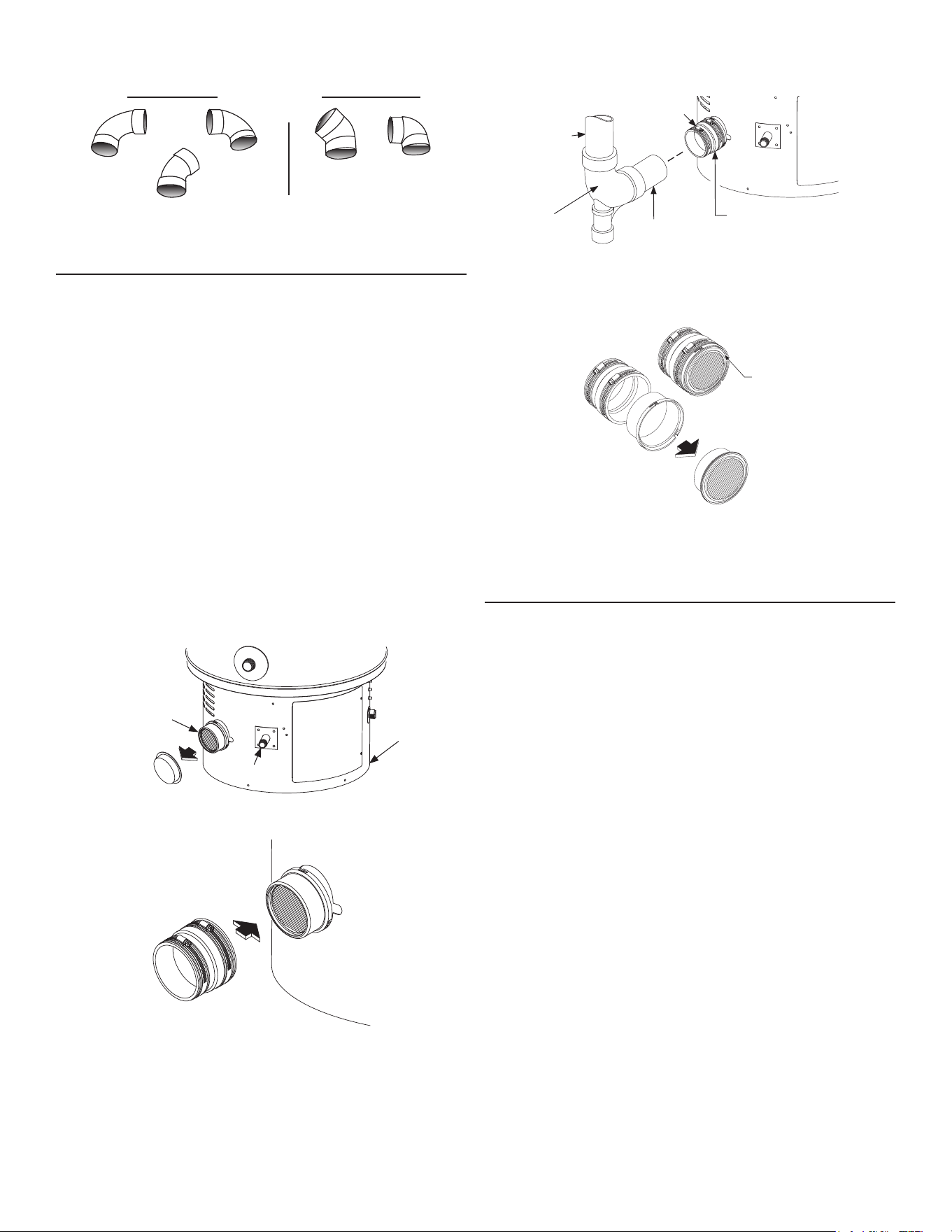
26
90° Short
Sweep
Elbow
90° Long Sweep
Elbow
45° Sweep Elbow
Correct Fittings Incorrect Fittings
45° Vent
Elbow
90° Vent
Elbow
Figure 13. Correct and Incorrect Pipe Fittings
INTEGRATED FILTER INSTALLATION
The air intake lter included with the unit must be installed according
to the installation instructions supplied with the lter. Installation
steps are shown in Figure 14-Figure 17.
When installing the adaptor rubber boot, note the following:
• Remove and discard the plastic cap from the outer clamshell
housing. See Figure 14.
• To connect heater to the air inlet, use the vent adaptor rubber boot
provided in the base skirt. The adaptor rubber boot is designed
for 3” venting (Figure 15).
Note: if there is a need for 2” venting, then use plastic pipe
ttings to transition down.
• Loosen the hose clamp at the adaptor rubber boot and slide the
plastic piping into the adaptor rubber boot. With piping in place,
tighten the hose clamp. Install a 3” x 3” x 2” drain/waste/vent
tting to trap airborne particulates. See Figure 15.
Note: If piping has been previously cut with a saw, be sure to remove
all burrs and plastic shavings from the piping before installing.
Note: The heater must never be operated without the lter media
installed.
Outer Clamshell
Housing With Filter
Base Skirt
Gas Piping
Remove
Plastic Cap
Figure 14. Remove Plastic Cap
Push On &
Tighten Clamp
Adaptor Rubber
Boot
Outer Clamshell
Housing
Figure 15. Adapter Rubber Boot
Hose Clamp
3" Plastic Pipe
Adaptor Rubber Boot
Outer Clamshell Housing
3" x 3" x 2"
DWV Fitting
Piped To
External Air
Supply
Figure 16. Air Inlet Piping
Adaptor
Rubber Boot
Remove
Filter Media
Filter Media shown inside
the Outer Clamshell Housing
Outer Clamshell
Housing
NOTE: if found difficult to
reattach the outer clamshell
housing to the internal clamshell
housing - apply a thin layer of silicone
grease to the surface of the black rubber
support of the Filter Media.
Figure 17. Filter Media
DIRECT VENT AIR INTAKE MOISTURE PROTECTION
The air intake piping in a direct vent system will normally not have
any moisture accumulation in it. However, in certain cases, moisture
may build up and needs to be drained. Typical situations include,
but are not limited to:
• Cold outdoor temperature, particularly if the air inlet is short,
• Heater being used mostly for space heating,
• Air inlet pipe has vertical rise near the heater and,
• High outdoor humidity.
Installations with any of these conditions are required to provide a
moisture drain with a trap that ows to a waste drain. See Figure 18
(page 27). Install a drain tee assembly and a trap in the inlet vent
as close to the water heater as possible. This is to drain any water
that may be in the combustion air pipe and prevent it from entering
the blower. The drain tubing in any installation should have a loop trap
and ow to an appropriate waste drain. The air intake drain line must
be entirely separate from the exhaust vent outlet condensate line.
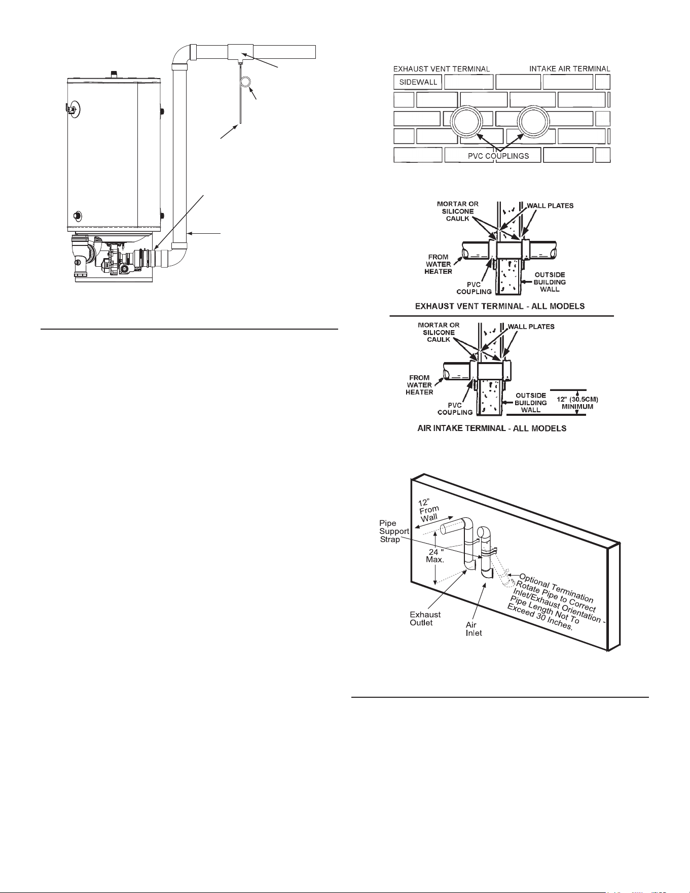
27
INSTALL TEE FITTING AS CLOSE TO
WATER HEATER INTAKE AIR
CONNECTION AS POSSIBLE
INTAKE AIR CONDENSATE TEE INSTALLATION
FIELD SUPPLIED
3" x 3" x 1/ 2" TEE
WITH HOSE BARB
FITTING INSTALLED
FACTORY
INTAKE AIR
CONNECTION
INTAKE
AIR
PIPING
CONNECT FIELD
SUPPLIED FLEXIBLE
DRAIN HOSE TO BARB
FITTING AND FORM A
LOOP WATER TRAP IN
DRAIN HOSE
RUN DRAIN HOSE
TO SUITABLE FLOOR
DRAIN SEPARATELY FROM
OTHER CONDENSATE DRAINS
Figure 18. Intake Air Condensate Tee Installation
HORIZONTAL VENT TERMINAL INSTALLATION
Note: If you are installing your system so that it vents through the
roof, please refer to Vertical Vent Terminal Installation (page
27).
1. After the points of termination have been determined (see Vent
Pipe Installation (page 24)use the cover plates as templates to
mark the holes for the vent pipes to be inserted through the wall.
BEWARE OF CONCEALED WIRING AND PIPING INSIDE
OF WALL. If the vent terminals are being installed on the outside
of a nished wall, it may be easier to mark both the inside and
outside wall. Align the holes by drilling a hole through the center of
the template from the inside through to the outside. The template
can now be positioned on the outside wall using the drilled holes
as a centering point for the template.
a. MASONRY SIDE WALLS Chisel an opening approximately
1/2” (1.3 cm) larger than the marked circle.
b. WOODEN SIDE WALLS Drill a pilot hole approximately one
quarter inch outside of the marked circle. This pilot hole is
used as a starting point for a saws-all or sabre saw blade. Cut
around the marked circle staying approximately one quarter
inch outside of the line. (This will allow the vent pipe to easily
slide through the opening. The resulting gap will be covered
by the vent terminal cover plates.) Repeat this step on the
inside wall if necessary.
2. Cut a length of pipe about 3.5” (8.9 cm) longer than the wall
thickness at the opening.
3. Glue the air intake terminal to the section of the pipe.
4. Slide the wall plate over pipe to stop against air intake terminal.
5. Place a bead of caulking (not supplied) around the gap between
the pipe and the wall. Place some of the caulking on the back of
the plate to hold it against the wall after installation.
6. If the air intake pipe is installed up to the wall, with a coupling
on the end against the wall opening, the pipe with the air intake
terminal can be prepared for gluing before inserting through the
wall. Slide the pipe through the wall and insert into coupling on
the other side of the wall. See Figure 19 and Figure 20.
7. See Figure 12 in Vent Pipe Installation (page 24) for standard and
alternate vent termination dimensions.
8. Refer to Figure 21 below for the Alternate Horizontal Termination
installation.
Figure 19. Installing Air Intake Pipe and Coupling
Figure 20. Standard Horizontal Termination- All Models
*Refer to Figure 11 for Inlet /Outlet Location Dimensions
Figure 21. Alternate Horizontal Termination
VERTICAL VENT TERMINAL INSTALLATION
The vertical inlet air termination requires a return bend or two short or
long sweep radius 90 elbows to keep the inlet downward and prevent
entry of rain. These elbows are considered part of the termination and
should not be included when calculating the maximum allowable vent
pipe length. See Figure 22 and Figure 23 (page 28) for the proper
location of the air inlet with respect to the exhaust outlet termination.
The air inlet and exhaust outlet terminations must be at least 12
inches above the roof line or anticipated snow levels.
WHEN TERMINATING THROUGH A ROOF, THE FOLLOWING
SPECIFICATIONS PERTAINING TO TERMINAL LOCATION
MUST BE FOLLOWED.
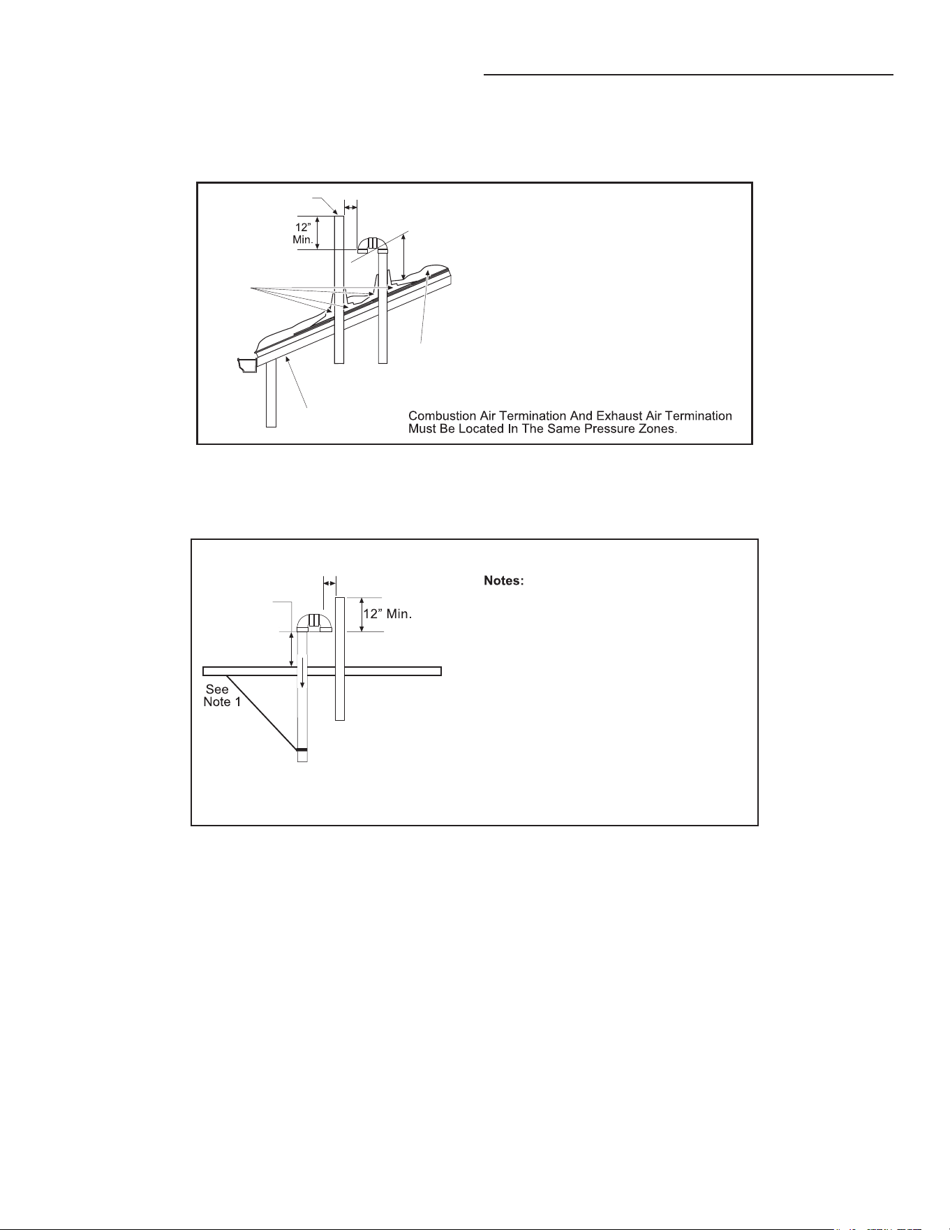
28
1. Support horizontal pipe every four feet. Support vertiocal pipe
every six feet.
2. Increase the 12 inch minimum above grade to keep terminal
openings above anticipated snow levels.
FLAT ROOF INSTALLATION
On flat roof installations the air intake and the exhaust vent
terminations must be a minimum of 24 inches (60 cm) above any
parapet, vertical wall or structure within 10 feet (3 m) horizontally.
PITCHED ROOF INSTALLATION (ALL MODELS)
Exhaust
Vent
See Note 3
12” Min.
See Note 2
Flashing
Roof Line
Anticipated
Snow Level
Notes:
1. Support Horizontal Pipe Every
Four Feet. Support Vertical Pipe
Every Six Feet.
2. Increase The 12 Inch Minimum
Above Grade To Keep Terminal
Openings Above Anticipated
Snow Levels.
3. See Figure 11 from "Vent Pipe
Termination" on page 23 to prop
erly
locate the inlet and exhaust
terminals.
Figure 22. Pitched Roof Installation (All Models)
FLAT ROOF INSTALLATION (ALL MODELS)
Combustion Air Termination and Exhaust Air Termination
Must Be Located in the Same Pressure Zones.
1
2" Min.
See Note 2.
See Note 3.
1. Support Horizontal Pipe Every
Four Feet. Support Vertical Pipe
Every Six Feet.
2. Increase The 12 Inch Minimum
Above Grade To Keep Terminal
Openings Above Anticipated
Snow Levels.
3. See Figure 11 from "Vent Pipe
Termination" on page 23 to prop
erly
locate the inlet and exhaust
terminals.
Figure 23. Flat Roof Installation (All Models)
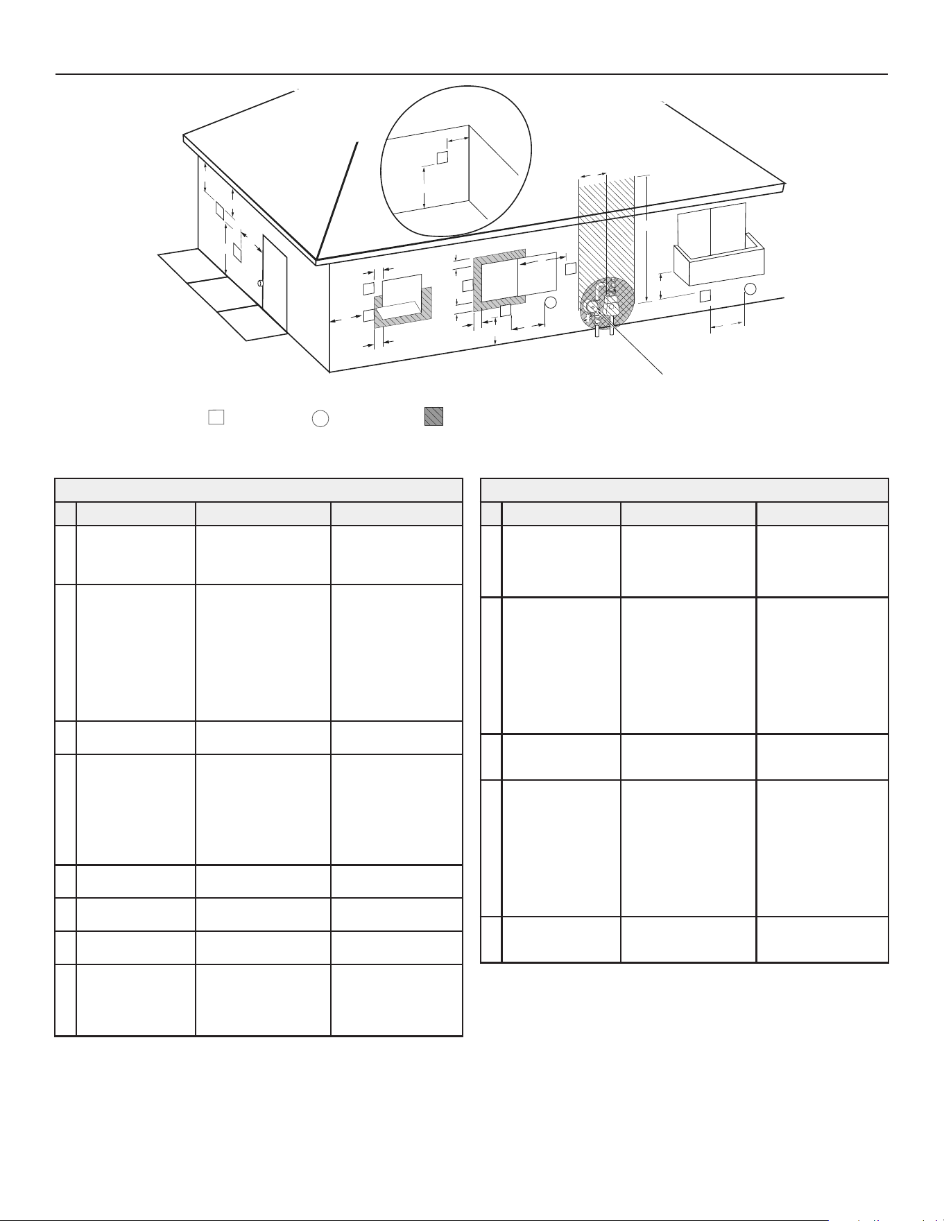
29
TERMINATION CLEARANCES SIDEWALL DIRECT VENT
Fixed
Closed
Operable
Fixed
closed
Operable
B
V
V
V
V
V
V
V
V
C
B
B
X
A
M
K
Regulator vent outlet
In the event no
regulator is present,
H and I can be
disregarded
.
V
Legend:
= Vent terminal
X
= Air supply inlet
= Area where terminal is not permitted
B
B
J
F
X
B
L
E
D
Inside
corner detail
V
A
G
H
15 ft
I
Figure 24. DOther Than Direct Vent Using Outdoor Air for Combustion
Termination Clearances for Sidewall Direct Vent
Type of Clearance
Canadian Installations
1
US Installations
2
A
Clearance above
grade, veranda,
porch, deck or
balcony
12 inches (30 cm) 12 inches (30 cm)
B
Clearance to window
or door that may be
opened
• 6 in (15 cm) for appli-
ances ≤ 10,000 Btuh
(3 kW)
• 12 in (30 cm) for appli-
ances > 10,000 Btuh
(3 kW) and ≤ 100,000
Btuh (30 kW),
• 36 in (91 cm) for appli-
ances > 100,000 Btuh
(30 kW)
• 4 feet (1.2 m) below or
to side of opening;
• 1 foot (30 cm) above
opening
C
Clearance to perma-
nently closed window
6 inches (15 cm)* 6 inches (15 cm)*
D
Vertical clearance
to ventilated sot
located above the
terminal within a
horizontal distance of
2 feet (61 cm) from
the center line of the
terminal
12 inches (30 cm) 12 inches (30 cm)
E
Clearance to unventi-
lated sot
12 inches (30 cm) 12 inches (30 cm)
F
Clearance to outside
corner
2 feet (60 cm)* 2 feet (60 cm)*
G
Clearance to inside
corner
18 inches (45 cm)* 18 inches (45 cm)*
H
Clearance to each
side of center line ex-
tended above meter/
regulator assembly
3 ft (91 cm) within a
height 15 ft (4.6 m)
Clearance in accordance
with local installa-
tion codes and the
requirements of the gas
supplier
Termination Clearances for Sidewall Direct Vent
Type of Clearance
Canadian Installations
1
US Installations
2
I
Clearance to service
regulator vent outlet
3 ft (1.83 m)
Clearance in accordance
with local installa-
tion codes and the
requirements of the gas
supplier
J
Clearance to a non
mechanical air supply
inlet into building or
combustion air inlet to
any other appliance
• 6 in (15 cm) for appli-
ances ≤ 10,000 Btuh
(3 kW)
• 12 in (30 cm) for appli-
ances > 10,000 Btuh
(3 kW) and ≤ 100,000
Btuh (30 kW)
• 36 in (91 cm) for appli-
ances >100,000 Btuh
(30 kW)
• 4 feet (1.2 m) below or
to side of opening;
• 1 foot (30 cm) above
opening
K
Clearance to a
mechanical air supply
inlet
6 feet (1.83 m)
3 feet (91 cm) above
if within 10 feet (3 m)
horizontally
L
Clearance above
paved sidewalk or
paved driveway
located on public
property
7 feet (2.13 m)†
7 ft (2.13 m) for me-
chanical draft systems
(Category I appliances);
vents for Category II and
IV appliances cannot
be located above public
walkways or other areas
where condensate
or vapor can cause a
nuisance or hazard
M
Clearance under
veranda, porch, deck,
or balcony
12 inches (30 cm) ‡ 12 inches (30 cm) ‡
1 In accordance with the current Natural Gas and Propane Installation Code, CSA B149.1.
2 In accordance with the current National Fuel Gas Code ANSI Z223.1/NFPA 54
† A vent shall not terminate directly above a sidewalk or paved driveway that is
located between two single family dwellings and serves both dwellings.
Where it may cause hazardous frost or ice accumulations on adjacent property
surfaces.
‡ Permitted only if veranda, porch, deck, or balcony is fully open on a minimum of
two sides beneath the oor.
* Clearance in accordance with local installation codes and the requirements of the
gas supplier and the manufacturer’s installation instructions.
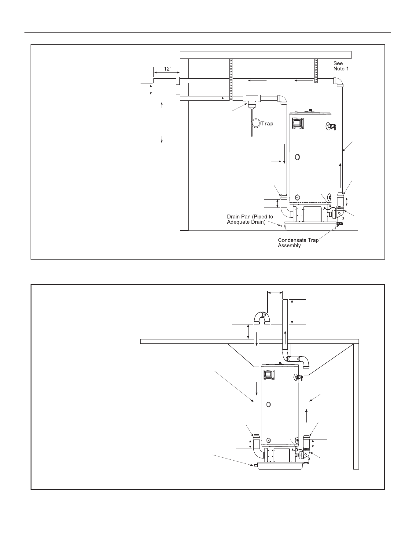
30
DIRECT VENT INSTALLATION DIAGRAMS
See
Note 6
See Note 5
See
Note 7
Tee with
Drain Tap
See
Note 5
See Note 4
See Note 4
3" x 2"
Reducer
3" x 2"
Reducer
Exhaust
Elbow
Assembly
To Drain*
See Note 3
Notes:
1. Support Horizontal Pipe Every
Four Feet. Support Vertical
Pipe Every Six Feet.
2. Increase the 12" minimum
above grade to keep terminal
openings above anticipated snow levels.
3. Slope all piping 1/8" per foot down
toward water heater.
4.
When venting with 2" pipe, a sufficient
length of 3" pipe (6" minimum) must be
inserted into the exhaust and inlet elbow
assembly before transitioning down to 2" pipe
with a 3" x 2" reducer.
5. For units with inputs of 150,000 BTU/hr and
below, use 2" or 3" pipe. For units with inputs
of 175,000 BTU/hr and above, use only 3" pipe.
6. See
Figure 12 from "Vent Pipe Termination"
(page 22) to properly locate the inlet and
exhaust terminals.
7. Connect blocked pressure switch hose to
condensate trap.
12" Min. Above
Grade or
Anticipated
Snow Level.
See Note 2.
*Direct vent combustion air intake drains are required in certain situations.
See the section on Direct Vent Air Intake Moisture Protection on page 24.
Figure 25. Sidewall Vent Installation (All Models)
See
Note 3
See
Note 6
See
Note 3
Drain Pan
(Piped To Adequate Drain)
See
Note 1
See
Note 1
See Note 1
See Note 5
12" Min.
12" Min. Above
Roof or Anticipated
Snow Level.
See Note 2.
Notes:
1. Support Horizontal Pipe Every Four Feet.
Support Vertical Pipe Every Six Feet.
2. Increase The 12 Inches Minimum Above
Grade To Keep Terminal Openings Above
Anticipated Snow Levels.
3. For units with inputs of 150,000 BTU/hr and
below, use 2" or 3" pipe. For units with inputs
of 175,000 BTU/hr and above, use only 3" pipe.
4. When venting with 2" pipe, a sufficient length of
3" pipe (6" minimum) must be inserted into the exhaust and
inlet elbow assembly before transitioning down to
2" pipe with a 3" x 2" reducer.
5. See
Figure 12 from "Vent Pipe Termination" on (page 22)
to properly locate the inlet and exhaust terminals.
6. Connect blocked pressure switch hose to
condensate trap.
*Direct vent combustion air intake drains are required in certain situations.
See the section on Direct Vent Air Intake Moisture Protection on page 24
See Note 4
3" x 2"
Reducer
Exhaust
Elbow
Assembly
See Note 4
3" x 2"
Reducer
Figure 26. Roof Vent Installation (All Models)
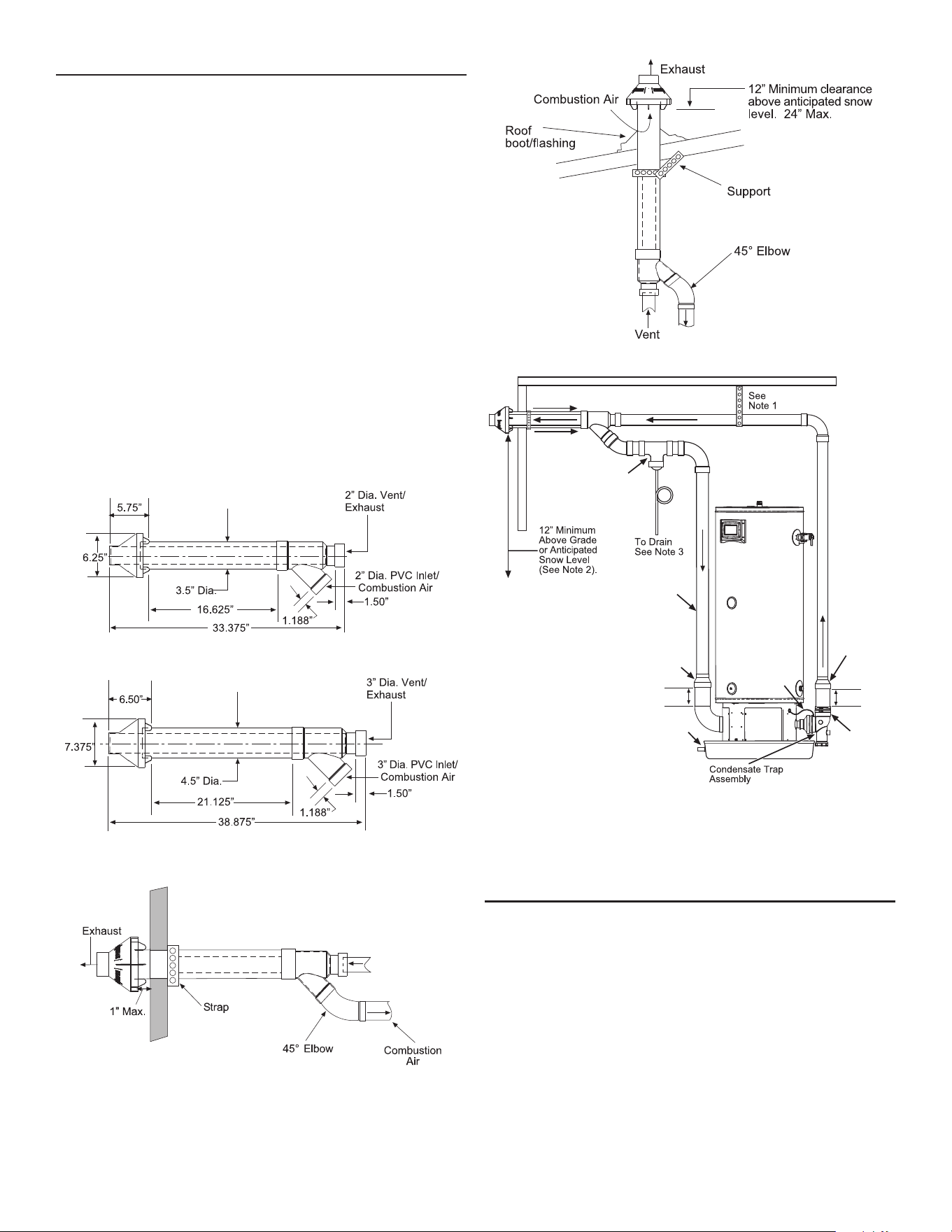
31
CONCENTRIC VENT INSTALLATION
For new installations of 130,000 & 150,000 btu/hr units, install 2”
Concentric vent kit model KGAVT0501CVT, part number 100093946.
For new installations of 175,000 & 199,000 btu/hr units, install 3”
Concentric vent kit model KGAVT0601CVT, part number 100093947.
See the manufacturer’s instructions for complete installation or call
the technical support number listed on the back cover of this manual.
For planning purposes, see Figure 27 through Figure 31 below for vent
terminal specications.
Note: When terminating concentric vents for additional units (all
models). See Venting Multiple Units (page 31).
Field-supplied pipe and fittings are required to complete the
installation.
SAFETY CONSIDERATIONS
Installing and servicing water heating equipment can be hazardous
due to gas and electrical components. Installation and service of
the concentric vent termination requires ability equivalent to that of
a qualied installer or qualied service technician. See Qualications
(page 8). All precautions in the literature, on tags, and labels
attached to the unit must be observed.
Follow all safety codes. Wear safety glasses and work gloves.
Figure 27. Two-Inch Concentric Vent
Figure 28. Three- Inch Concentric Vent
Figure 29. Through-the-Wall Termination
Figure 30. Through-the-Roof Termination
Tee with
Drain Trap
See Note 4
Trap
NOTES:
1. Support Horizontal Pipe Every Four Feet.
Support Vertical Pipe Every Six Feet.
2. Increase The 12” Minimum Above
Grade To Keep Inlet Opening
Above Anticipated
Snow Levels.
3. Slope All Piping 1/8” Per
Foot
Down Toward The
Water Heater.
4. For units with inputs of
150,000 BTU/hr
and below,
use 2" or 3" pipe. For units
with
inputs of
175,000 BTU/hr
and above,
use only 3" pipe.
5. When venting with 2" pipe, a sufficient
length of 3" pipe (6" minimum) must be
inserted into the exhaust and inlet elbow
assembly before transitioning down to
2" pipe with a 3" x 2" reducer.
6. Connect blocked pressure switch hose
to condensate trap.
See Note 5
See
Note 6
Drain Pan
(Piped to
Adequate
Drain)
3" x 2"
Reducer
Exhaust
Elbow
Assembly
See Note 5
3" x 2"
Reducer
Figure 31. Concentric Vent Piping Installation
VENTING MULTIPLE UNITS
VENTING ADDITIONAL WATER HEATERS
(130,000 & 150,000 BTU/HR MODELS)
When using two water heaters with inputs of 150,000 BTH/HR or
below, install vent terminations using either Method A or Method B
below:
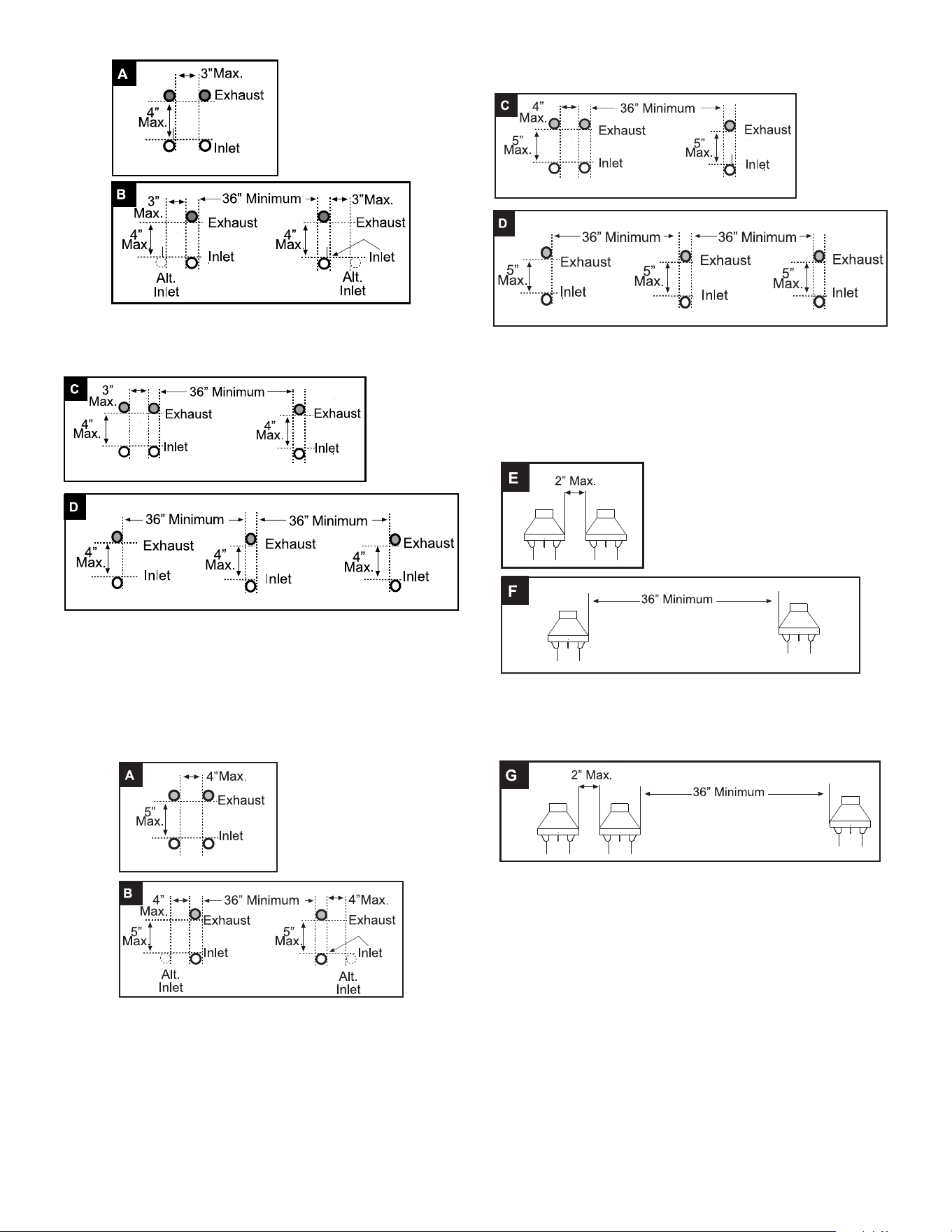
32
Figure 32. Multi-Unit Venting Methods A and B
When using three or more water heaters with inputs of 150,000 BTH/
HR or below, install vent terminations per Method C or Method D:
Figure 33. Multi-Unit Venting Methods C and D
VENTING ADDITIONAL WATER HEATERS (175,000 & 199,000
BTU/HR MODELS)
When using two water heaters with inputs of 175,000 BTH/HR or
above, install vent terminations using either Method A or Method
B below:
Figure 34. Multi-Unit Venting Methods A and B
When using three or more water heaters with inputs of 175,000 BTH/
HR or above, install vent terminations per Method C or Method D:
Figure 35. Multi-Unit Venting Methods C and D
CONCENTRIC VENTING MULTIPLE WATER HEATERS
(ALL MODELS)
When concentric venting two water heaters, install vent terminations
using either Method E or Method F below:
Figure 36. Multiple-Concentric-Unit Venting Methods E and F
When concentric venting three or more water heaters, install vent
terminations using Method G below:
Figure 37. Multiple-Concentric-Unit Venting Method G
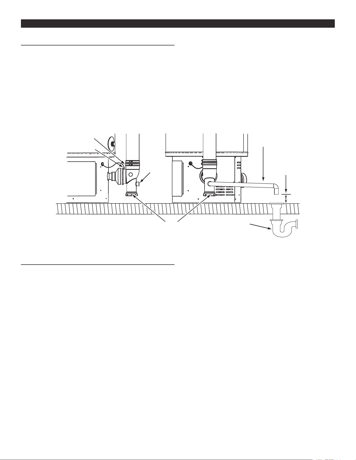
33
WATER HEATER INSTALLATIONWATER HEATER INSTALLATION
CONDENSATE DRAIN INSTALLATION
1. Ensure the water heater’s enable/disable switch is in the “disable”
position.
2. Install a 1/2 inch PVC condensate drain line between condensate
drain connection on the Exhaust/Condensate Elbow and a
suitable building drain with a slight downward slope to drain. The
exhaust elbow has a “built in” condensate trap. Do not install
an additional trap in the condensate drain piping. See Figure 38.
3. Terminate the condensate drain piping with an elbow above the
drain. Ensure that any discharge will exit the condensate drain
line no more than 6 inches (15.2 cm) above a suitable building
drain, or external to the building. See Figure 38.
Note: In cold climates it is recommended the condensate drain
be terminated at a suitable drain inside the building.
4. Ensure the condensate drain line is not elevated above the
condensate drain connection on the Exhaust/Condensate Elbow.
See Figure 38.
5. Brace the condensate drain line with oor mounted standos
every three feet.
6. Ensure the condensate drains freely during start up and the
condensate clean out cap is on and tight when unit is in operation.
7. Condensate clean out cap must be on and tight when unit is in
operation.
8. Connect blocked pressure switch hose to condensate trap
(pressure port).
DRAIN LINE TO
TERMINATE NO
MORE THAN 6
INCHES (15.2 cm
)
ABOVE DRAIN
BUILDING
DRAIN
1/2” NPT
CONDENSATE
DRAIN
CONNECTION
CONDENSATE
CLEANOUT
EXHAUST/CONDENSATE
(VENT) ELBOW
PRESSURE PORT
CONDENSATE DRAIN
LINE - FIELD
INSTALLED
Figure 38. Condensate Drain Installation
SUPPLY GAS LINE INSTALLATION
Contact your local gas utility company to ensure that adequate gas
service is available and to review applicable installation codes for
your area.
Be sure that the gas meter has sucient capacity to supply the
rated gas input of the water heater as well as the requirements of
all other gas red equipment supplied by the meter. If the gas meter
is undersized, the gas company will have to install a properly sized
gas meter.
Make sure the gas supplied is the same type listed on the water
heaters rating label.
The gas piping must be installed according to all local and state codes
or in absence of local and state codes with the National Fuel Gas Code,
ANSI Z223.1 (NFPA 54)-current edition. Canadian installations must be
performed in accordance with CAN/CSA-B149.1-current edition.
Schedule 40 Steel or Wrought Iron Pipe is the preferred material for
the gas line of this water heater. It is imperative to follow the sizing
recommendations in the latest version of the National Fuel Gas Code
if Corrugated Stainless Steel Tubing (CSST) is used as the gas line
for this water heater.
Table 10, Table 11, and Table 12 (page 34) are provided as a sizing
reference for commonly used gas pipe materials. Consult the National
Fuel Gas Code for the recommended gas pipe size of other materials.
Follow the instructions below and reference Figure 39 (page 34)
for gas piping installation.
1. Apply thread sealing compounds (pipe dope/ Teflon tape)
sparingly and only to the male threads of the pipe joints. Do not
apply sealing compound to the rst two threads. Use pipe dope
or Teon tape marked as being resistant to the action of liquid
petroleum (LP/propane) gases.
2. Install a readily accessible manual shut-o valve in the gas supply
line as recommended by the local utility. Know the location of this
valve and how to turn o the gas to this unit.
3. Install a sediment trap as shown. The sediment trap must be
no less than 3 inches long for the accumulation of dirt, foreign
material and water droplets.
4. Install a ground union between the water heater and the manual
shut-o valve. This is to allow easy servicing. See Figure 39 (page
34).
5. Turn the gas supply on and check for leaks. See Gas Line Leak
Testing (page 35). Use a chloride-free soap and water solution
(bubbles forming indicate a leak) or other approved method.
Note: Units with inputs of 175,000 BTU/HR or above must have a
minimum of 3/4” NPT gas pipe supplied to the water heater.
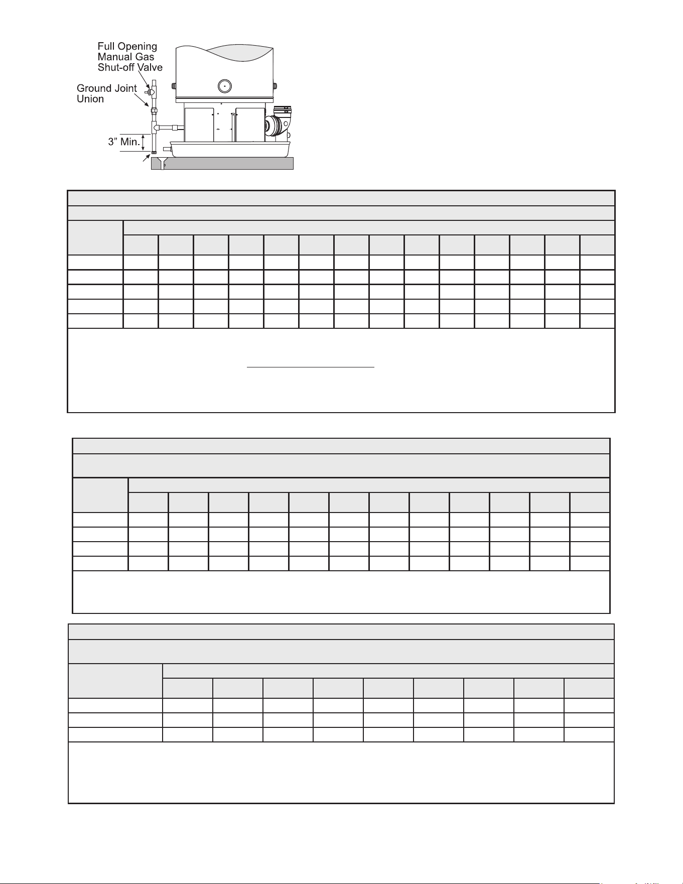
34
Sediment Trap
Figure 39. Supply Gas Line Installation
Table 10. Natural Gas Capacity (Cu. ft/hr)
Capacity of gas pipe of dierent diameters and lengths in cu. ft. per hr. with pressure drop of 0.3 in. and specic gravity of 0.60 (natural gas).
Nominal Iron
Pipe Size (in.)
Length of Pipe (feet)
10 20 30 40 50 60 70 80 90 100 125 150 175 200
1/2 132 n/a n/a n/a n/a n/a n/a n/a n/a n/a n/a n/a n/a n/a
3/4 278 190 152 130 115 105 96 n/a n/a n/a n/a n/a n/a n/a
1 520 350 285 245 215 195 180 170 160 150 130 120 110 100
1-1/4 1050 730 590 500 440 400 370 350 320 305 275 250 220 210
1-1/2 1600 1100 890 760 670 610 560 530 490 460 410 380 350 320
After the length of pipe has been determined, select the pipe size which will provide the minimum cubic feet per hour required for the
gas input rating of the water heater. By formula:
Cu. Ft. Per Hr. Required = Gas Input of Water Heater (BTU/HR)
Heating Value of Gas (BTU/FT
3
)
The gas input of the water heater is marked on the water heater data plate. The heating value of the gas (BTU/FT3) may be determined
by consulting the local natural gas utility.
Table 11. LP Gas Capacity - Iron Pipe
Maximum capacity of pipe in thousands of BTU per hour of undiluted liqueed petroleum gases (at 11 inches water column pressure).
Based on a Pressure Drop of 0.5 Inch Water Column.
Nominal Iron
Pipe Size (in.)
Length of Pipe (feet)
10 20 30 40 50 60 70 80 90 100 125 150
1/2 275 189 152 n/a n/a n/a n/a n/a n/a n/a n/a n/a
3/4 576 393 315 267 237 217 196 185 173 162 146 132
1 1071 732 590 504 448 409 378 346 322 307 275 252
1-1/4 2205 1496 1212 1039 913 834 771 724 677 630 567 511
Source: Natural Gas Propane Installation Code CAN/CSA B149.1
Example: Input BTU requirement of the water heater, 199,000 BTUH
Total pipe length, 80 feet = 1” IPS required.
Table 12. LP Gas Capacity - Copper Tubing
Maximum capacity of pipe in thousands of BTU per hour of undiluted liqueed petroleum gases (at 11 inches water column pressure).
Based on a Pressure Drop of 0.5 Inch Water Column.
Copper Tubing O.D. Size
(in.)
Length of Pipe (feet)
10 20 30 40 50 60 80 100 125
5/8 206 141 n/a n/a n/a n/a n/a n/a n/a
3/4 348 239 192 164 146 132 n/a n/a n/a
7/8 536 368 296 253 224 203 174 154 137
Source: Natural Gas Propane Installation Code CAN/CSA B149.1
Example: Input BTU requirement of the water heater, 199,000 BTUH
Total pipe length, 50 feet = 7/8” IPS required.
Additional tables are available in the current edition of the Natural Gas Propane Installation Code CAN/CSA B149.1.
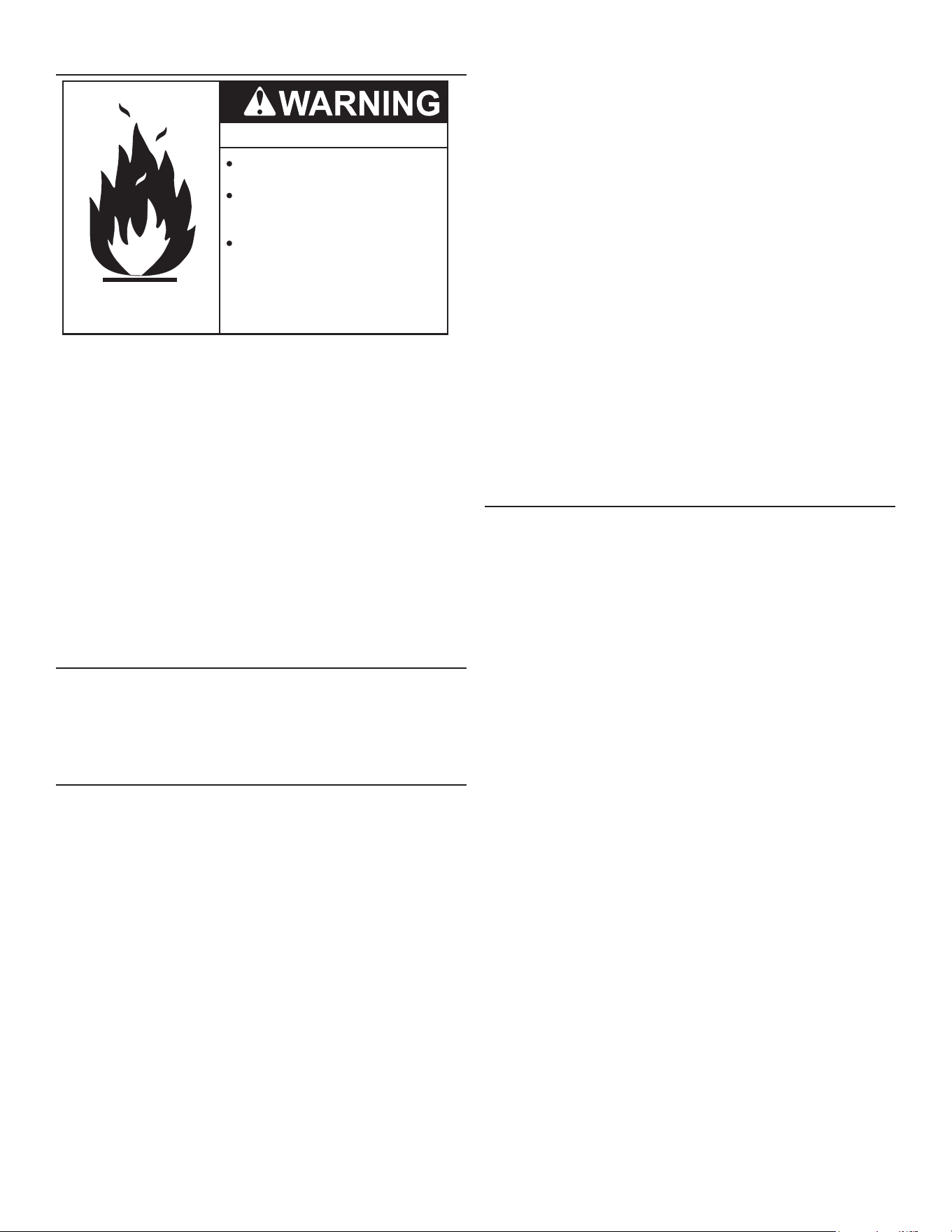
35
GAS LINE LEAK TESTING
Fire and Explosion Hazard
Leak test gas connections
before placing the water heater in
operation.
Disconnect gas piping at main
gas shutoff valve before leak
testing.
Use joint compound or Teflon tape
compatible with propane gas.
● Install sediment trap in
accordance with
NFPA54 and
CAN/CSA B149.1.
Any time work is done on the gas supply system perform a leak test
to avoid the possibility of re or explosion.
1. For test pressures exceeding 1/2 psi (3.45 kPa) disconnect
the water heater and its Main Gas Shuto Valve from the gas
supply piping system during testing. See Figure 39 (page 34).
The gas supply line must be capped when disconnected from
the water heater.
2. For test pressures of 1/2 psi (3.45 kpa) or less, the water heater
need not be disconnected, but must be isolated from the supply
gas line by closing the Main Gas Shuto Valve during testing.
3. Paint all supply gas line joints and connections upstream of the
water heater with a rich soap and water solution to test for leaks.
Bubbles indicate a gas leak. Do not use matches, candles, ame
or other sources of ignition for this purpose.
4. Repair any leaks before placing the water heater in operation.
PURGING
Gas line purging is required with new piping or systems.
Purging should be performed per the current edition of NFPA 54
the National Fuel Gas Code or CAN/CSA B149.1 Natural Gas and Propane
Installation Code.
ELECTRICAL WIRING
If you lack the necessary skills required to properly install the
electrical wiring to this water heater, do not proceed but have a
qualied electrician perform the installation. See Power Supply (page
18) for additional requirements.
When making the electrical connections, always make sure:
• The voltage and frequency must correspond to that specied
on the water heater data plate on the front of the water heater.
• The electrical supply has the proper overload fuse or breaker
protection. The heater draws less than 7 amps.
• Wire sizes, connections and conduits comply with all applicable
codes.
• The water heater and electrical supply are properly grounded.
• This water heater must be “hard-wired” do not use an extension
cord to supply electrical power to this water heater.
Note: The wiring diagram can be found in Figure 53 (page 64).
Always reference the wiring diagram(s) for the correct
electrical connections.
When installing the electrical wiring to the water heater:
1. Shut o the power at the electrical service box.
2. Loosen the screws securing the access panel to the electrical
compartment. (The electrical wiring diagram for all models can
be found on the inside of the access panel at the base of the
water heater. Set the access panel aside.
3. Connect the electrical supply to the water heater in accordance
with local utility requirements and codes. Use only a dedicated
electrical circuit containing a properly sized fuse or circuit breaker.
Maximum overload protection should not exceed 15 amperes.
4. Connect this circuit (directly from the electrical service box) to an
electrical disconnect switch.
5. Ground the water heater by connecting the electrical service
ground wire to the green ground wire (provided).
Note: The power supply to this water heater must be properly
polarized, [120 volts from the hot lead (black) to ground and
0 volts from the neutral lead (white) to ground] otherwise, the
unit will not operate.
6. After making all electrical connections, completely ll the tank with
water and check all connections for leaks. Open the nearest hot
water faucet and let it run for 3 minutes to purge the water lines
of air and sediment and to ensure complete lling of the tank.
The electrical power may then be turned on. See Start Up (page
49) for the complete instructions.
ENABLE/DISABLE CIRCUIT
(FOR BUILDING MANAGEMENT SYSTEMS)
The water heaters covered in this manual are equipped with an
enable/disable circuit for use with eld supplied external supervisory
controls such as time clocks or building management systems. The
enable/disable circuit may be used to disable heating operation
during periods when the building is unoccupied or there is no demand
for hotwater.
To use the enable/disable circuit it must rst be activated by selecting
the “Use External Enable” from the UIM. Field-supplied wiring is then
installed between the water heater’s CCB and a set of “dry contacts”
(no voltage or load) on the eld supplied external control.
Note: The water heater’s enable/disable circuit is a switching circuit
only: Do not apply external voltage or connect any load (IE:
relay coil) to this circuit. This will damage the CCB circuit board
and is not covered under the limited warranty.
CONNECTING AN EXTERNAL SUPERVISORY CONTROL
The enable/disable circuit is accessed from the CCB’s J17 plug inside
the CCB enclosure. See Figure 3 and Figure 4 (page 13)to locate
the CCB enclosure and Figure 52 (page 63) for the CCB layout.
Install eld wiring to the enable/disable circuit:
1. Turn o power at the water heater’s enable/disable switch and
the breaker that supplies power to the water heater.
2. Locate the CCB enclosure.
3. Carefully remove the Temperature Probe connectors and CCB
enclosure cover.
4. Locate pins 1 and 2 on the CCB J17 plug. See Figure 52 (page
63).
5. Connect the two eld supplied control wires to pins 1 and 2 on
the CCB J17 plug.
6. Thread the control wires out of the CCB enclosure with the other
wiring and carefully replace the CCB enclosure cover. Ensure
all wiring is routed through the intended area provided for strain
relief. Ensure no wiring is being pinched.
7. Reinstall the CCB enclosure cover.
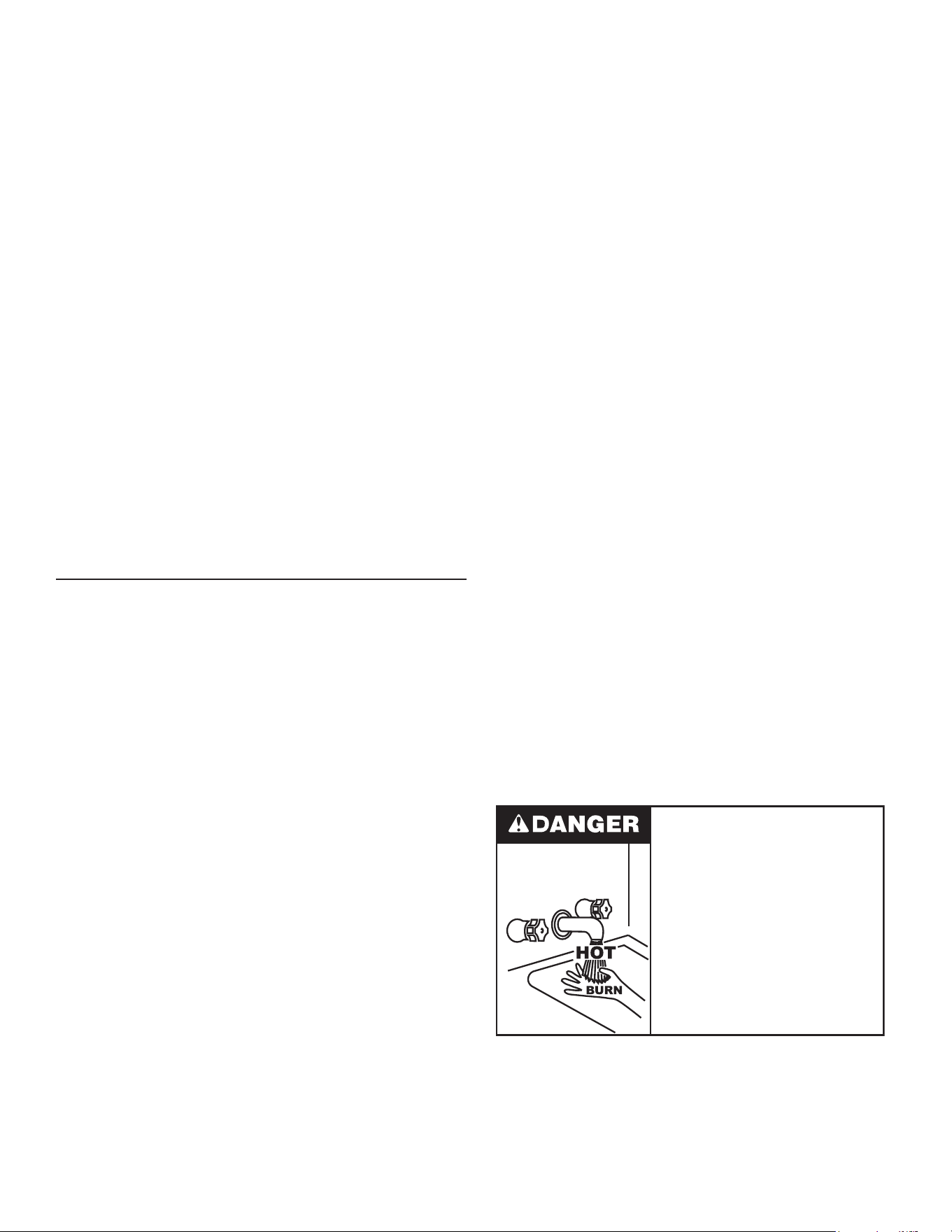
36
8. Route the control wires inside the junction box on the top of the
water heater. See Figure 3 (page 12) to locate the junction
box. Use an available knock-out to route the wires inside the
junction box.
9. Install eld supplied control wiring and conduit as required by
national and local codes between the water heater’s junction box
and the external supervisory control. Connect the wiring from the
external control to the control wires inside the junction box using
wire nuts and electrical tape.
10. Connect the control wiring to a set of dry contacts on the external
control. Follow the control manufacturer’s instructions for making
connections.
11. Restore power to the water heater.
12. From the water heaters UIM “Heater Information Screen” select
“Use External Enable” and change to “Yes”. See Figure 3 (page
12) to locate the UIM.
Note: Whenever the external control opens the set of dry contacts
used, water heating operation will be disabled. Whenever the
external control closes the set of dry contacts used, water
heating operation will be enabled. A diagonal line and circle
appears over the thermometer icon on the UIM when water
heating operation is disabled. See the status icon descriptions
in Table 14 (page 40).
Note: Ensure the water heater is protected from freezing
temperatures when water heating operation is disabled.
Damage to the water heater caused by freezing temperatures
is not covered under the limited warranty.
WATER LINE CONNECTIONS
The water piping installation must conform to these instructions and
to all local and national code authority having jurisdiction. Good
practice requires that all heavy piping be supported.
Read and observe all requirements in the following sections before
installation of the water piping begins:
1. Mixing Valves (page 19).
2. Dishwashing Machines (page 19).
3. Temperature-Pressure Relief Valve (page 21).
4. Closed Water Systems and Thermal Expansion (page 20).
WATER PIPING DIAGRAMS
This manual provides detailed water piping diagrams for typical
methods of application for the water heaters. See Piping Diagrams
(page 65).
The water heater may be installed by itself, or with a separate storage
tank. When used with a separate storage tank, the circulation may
be either by gravity or by means of a circulating pump. When a
circulating pump is used, it is important to note that the ow rate
should be slow so that there will be a minimum of turbulence inside
the water heater storage tank.
Adjust ow by throttling a full port ball valve installed in the circulating
line on the outlet side of the pump. Never throttle ow on the suction
side of a pump. See Figure 58 (page 66).
Note: In addition to the factory installed Temperature-Pressure
Relief Valve (T&P valve) on the water heater, each remote
storage tank that may be installed and piped to a water heating
appliance must also have its own properly sized, rated and
approved Temperature-Pressure Relief Valve installed. See
Temperature-Pressure Relief Valve (page 21).
Call the toll free technical support phone number listed on the back
cover of this manual for further assistance in sizing a T&P valve for
remote storage tanks.
THERMOMETERS (NOT SUPPLIED)
Thermometers are installed in the water piping system as a means
of detecting the temperature of the hot water supply at critical points
in the system. Field supplied thermometers should be obtained and
installed. See Piping Diagrams (page 65).
WATER (POTABLE) HEATING AND SPACE HEATING
1. All water piping components connected to the water heater that
are for space heating applications shall be suitable for use with
potable water.
2. Toxic chemicals, such as those used for boiler treatment, must
NEVER be introduced into this system.
3. The water heaters covered in this manual may never be
connected to any existing heating system or component(s)
previously used with non-potable water heating appliance.
4. When the system requires water for space heating that exceed
safe temperatures at domestic water xtures, a mixing valve
must be installed. See Mixing Valves (page 19).
5. These water heaters cannot be used in space heating
applications only.
HOTTER WATER CAN SCALD:
Water heaters are intended to produce hot water. Water heated to
a temperature which will satisfy space heating, clothes washing,
dish washing, cleaning and other sanitizing needs can scald and
permanently injure you upon contact. Some people are more likely
to be permanently injured by hot water than others. These include
the elderly, children, the physically or developmentally disabled. If
anyone using hot water ts into one of these groups or if there is a
local code or state law requiring a certain temperature water at the
hot water tap, then you must take special precautions. In addition
to using the lowest possible temperature setting that satises your
hot water needs, a means such as a mixing valve should be used at
the hot water taps used by these people or at the water heater. See
Figure 9 (page 19). Valves for reducing point of use temperature
by mixing cold and hot water are also available:
Water temperature over 125°F (52°C)
can cause severe burns instantly
resulting in severe injury or death.
Children, the elderly and the
physically or mentally disabled are at
highest risk for scald injury.
Feel water before bathing or
showering.
Temperature limiting devices such as
mixing valves must be installed
when required by codes and to
ensure safe temperatures at fixtures.
Consult a Qualied Installer or Service Agency. Follow manufacturer’s
instructions for installation of the valves. Before changing the factory
setting on the thermostat, read Temperature Regulation (page 38).
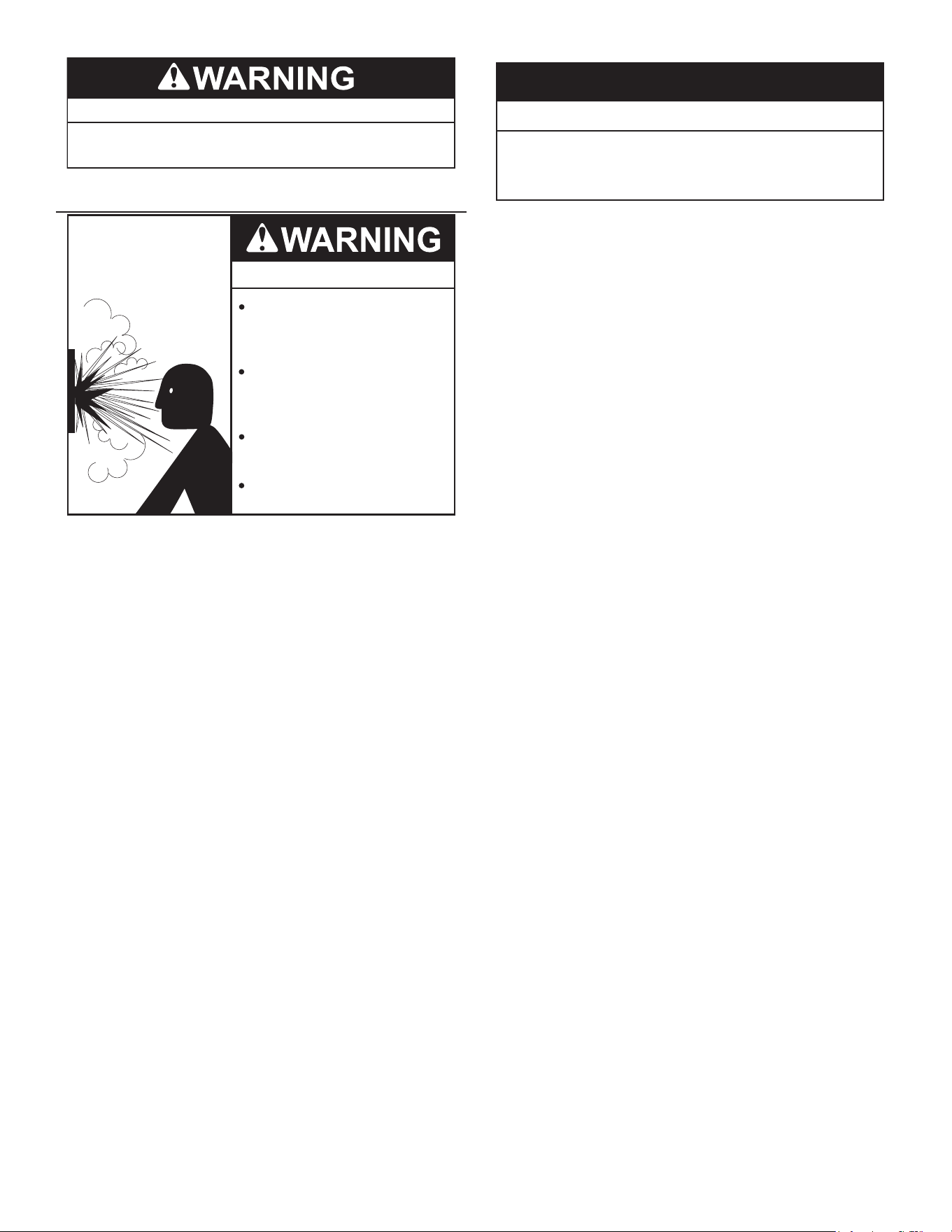
37
Toxic Chemical Hazard
•
Do not connect to non-potable water system.
T&P VALVE DISCHARGE PIPE
Explosion Hazard
Temperature-Pressure Relief Valve
must comply with ANSI Z21.22-
CSA 4.4 and ASME code.
Properly sized temperature-
pressure relief valve must be
installed in opening provided.
Can result in overheating and
excessive tank pressure.
Can cause serious injury or death.
This water heater is provided with a properly rated/sized and
certied combination temperature - pressure (T&P) relief valve by
the manufacturer. See Temperature-Pressure Relief Valve (page 21)
for information on replacement and other requirements.
Water Damage Hazard
Temperature-Pressure Relief Valve discharge
pipe must terminate at adequate drain.
•
CAUTION
Install a discharge pipe between the T&P valve discharge opening
and a suitable oor drain. Do not connect discharge piping directly to
the drain unless a 6” (15.2 cm) air gap is provided. To prevent bodily
injury, hazard to life, or property damage, the Temperature-Pressure
Relief Valve must be allowed to discharge water in adequate
quantities should circumstances demand. If the discharge pipe is
not connected to a drain or other suitable means, the water ow may
cause property damage.
T&P VALVE DISCHARGE PIPE REQUIREMENTS:
• Shall not be smaller in size than the outlet pipe size of the valve,
or have any reducing couplings or other restrictions.
• Shall not be plugged or blocked.
• Shall not be exposed to freezing temperatures.
• Shall be of material listed for hot water distribution.
• Shall be installed so as to allow complete drainage of both the
Temperature-Pressure Relief Valve and the discharge pipe.
• Must terminate a maximum of six inches above a oor drain or
external to the building. In cold climates, it is recommended that
the discharge pipe be terminated at an adequate drain inside
the building.
• Shall not have any valve or other obstruction between the
Temperature-Pressure Relief Valve and the drain.
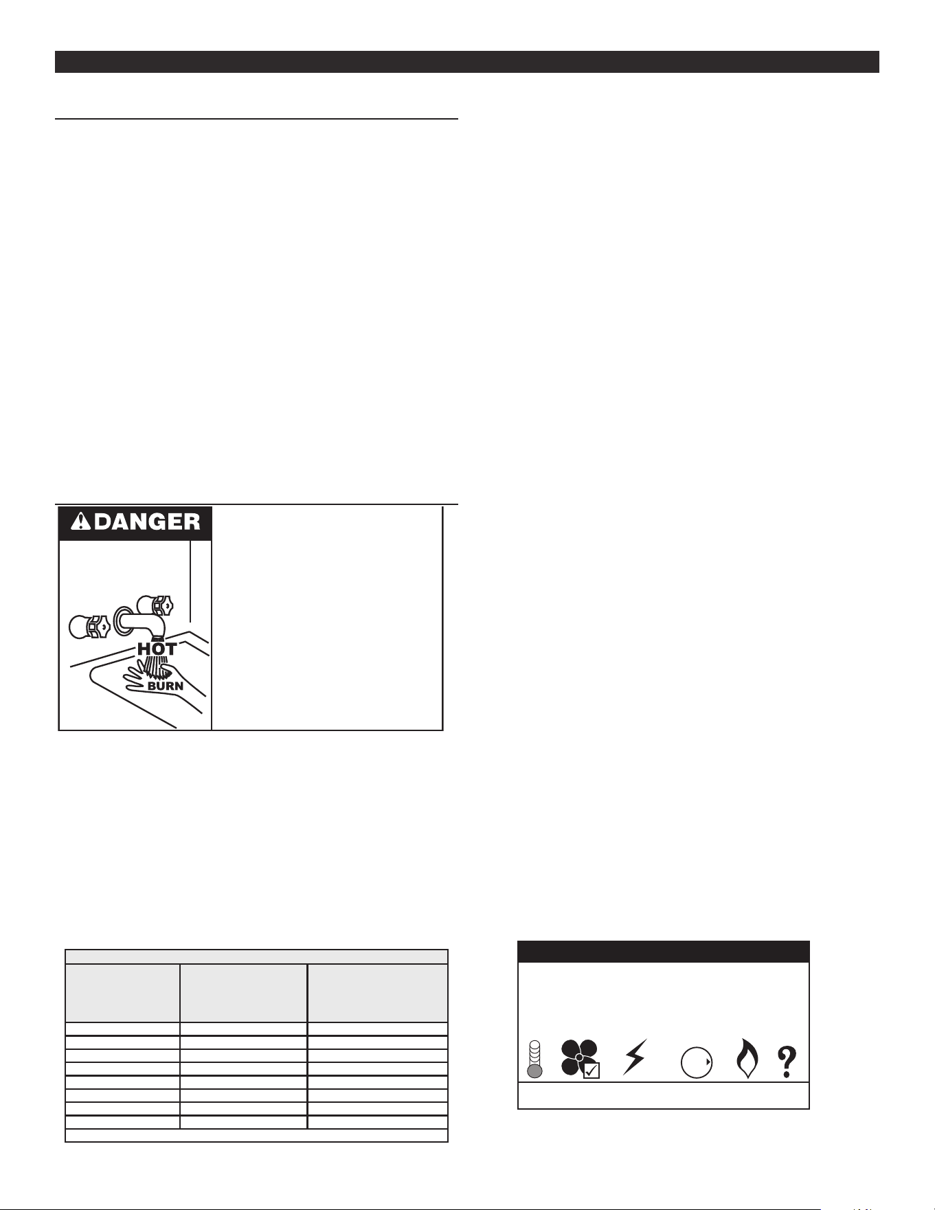
38
TEMPERATURE REGULATIONTEMPERATURE REGULATION
HIGH TEMPERATURE LIMIT CONTROL (ECO)
This water heater is equipped with an ECO (energy cut out) non
adjustable high temperature limit switch. The ECO is a normally
closed switch that opens (activates) on a rise in temperature. The
ECO is located inside the Temperature Probe (two red wires).
The ECO switch contacts will open when the water temperature
reaches approximately 202°F (94°C) and close at approximately
140°F (49°C).
If the ECO activates (contacts open) due to abnormally high water
temperatures in the storage tank, the control system will immediately
de-energize the 24 VAC Gas Control Valve and end current heating
cycle. The control system will lock out disabling further heating
operation. The control system will display the Energy Cut Out (ECO)
Fault message on the LCD screen. It is important that a Qualied
Service Technician be contacted to determine the reason for ECO
activation before resetting the ECO. Once the reason has been
determined and corrected the ECO can be reset as follows:
Should the ECO activate, water temperature must drop below
140°F (49°C) before the control system can be reset. Once water
temperature has cooled below this point the power supply to water
heater must be turned o and on again to reset the control system.
THERMOSTAT CONTROL
Water temperature over 125°F (52°C)
can cause severe burns instantly
resulting in severe injury or death.
Children, the elderly and the
physically or mentally disabled are at
highest risk for scald injury.
Feel water before bathing or
showering.
Temperature limiting devices such as
mixing valves must be installed
when required by codes and to
ensure safe temperatures at fixtures.
Hot water temperatures required for automatic dishwasher and
laundry use can cause scald burns resulting in serious personal
injury and/or death. Table 13 shows the approximate time-to-burn
relationship for normal adult skin.
The temperature at which injury occurs varies with the person’s age
and duration of exposure. The slower response time of children,
the elderly or disabled persons increases the hazards to them. If
anyone using hot water provided by the water heater being installed
ts into one of these groups or if there is a local code or state law
requiring a certain water temperature at the point of use, then special
precautions must be taken.
Table 13. Burn Time at Various Temperatures
Water
Temperature
°F (°C)
Time for 1st Degree
Burn
(Less Severe Burns)
Time for Permanent
Burns
2nd & 3rd Degree
(Most Severe Burns)
110 (43.3) (normal shower temp.)
116 (46.7) (pain threshold)
116 (46.7) 35 minutes 45 minutes
122 (50) 1 minute 5 minutes
131 (55) 5 seconds 25 seconds
140 (60) 2 seconds 5 seconds
149 (65) 1 second 2 seconds
154 (67.8) instantaneous 1 second
(U.S. Government Memorandum, C.P.S.C., Peter L. Armstrong, Sept. 15, 1978)
In addition to using the lowest possible temperature setting that
satises the demand of the application, a mixing valve can be
installed at the water heater or at the hot water taps to further reduce
system water temperature. See Figure 9 (page 19).
Never allow small children to use a hot water tap or draw their own
bath water. Never leave a child or disabled person unattended in a
bathtub or shower.
The water heater should be located in an area where the general
public does not have access to set temperatures.
Setting the Operating Set Point at 120°F (49°C) will reduce the risk of
scalds. Some States require settings at specic lower temperatures.
Check with the code authority having jurisdiction..
The water heaters covered in this manual are equipped with an
electronic control system to regulate water temperature inside the
storage tank. The control system senses temperature from two
factory installed temperature probes, one installed in the top of the
storage tank and one installed near the bottom. See Figure 2 and
Figure 3 in Features and Components (page 11).
The “Operating Set Point” is adjusted to regulate water temperature
inside the tank. This is an adjustable user setting in the control
system’s “Temperature Menu.” This and all control system menus
are accessed through the UIM (user interface module) located on
the front of the water heater. See Figure 38 (page 33).
The “Operating Set Point” is adjustable from 90°F (32°C) to 181°F
(83°C). The factory setting is 120°F (49°C). See Operating Set Point
And Differential Adjustment (page 42) for instructions on how to
adjust the Operating Set Point and other settings.
Set the Operating Set Point at the lowest setting which produces
acceptable hot water supply. This will always provide the most
ecient operation.
MODULATION
The water heaters covered by this manual are capable of modulating
their ring rate. The CCB monitors water temperature in the tank and
regulates the ring rate to achieve the target temperature setpoint.
The ring rate is dictated by the hot water draw, proximity to the tank
temperature setpoint, and various other temperature limitations.
HIGH TEMPERATURE APPLICATIONS
Higher operating temperatures cause more wear on all water heaters
and will decrease the life span of the water heater. Consider installing
a small booster water heater for high temperature applications, such
as commercial dishwashers, to raise the outlet temperature from the
larger primary water heater to the desired point of use temperature.
Contact your local distributor or call technical support phone number
listed on back cover of this manual for further technical assistance.
Tank Temperature 103°F
Operating Set Point 120°F
Status: Heating
MENU HELP
GAS
OFF
O
N
Figure 40. Control Desktop Screen
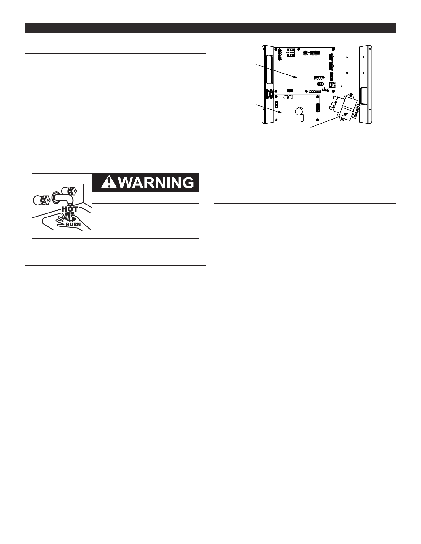
39
CONTROL SYSTEM OPERATIONCONTROL SYSTEM OPERATION
LIMITING THE RISK OF SCALDING
This water heater can make water hot enough to cause severe burns
instantly, resulting in severe injury or death.
• Feel water before bathing or showering
• To reduce the risk of scalding, install thermostatic mixing valves
(temperature limiting valves) at each point of use. These valves
automatically mix hot and cold water to limit the temperature at
the tap. Follow manufacturer’s instructions for installation and
adjustment of the valves.
• The gas control valve on this water heater has been factory
set to its lowest setting to reduce the risk of scalding. Higher
temperatures increase the risk of scalding, but even at 120°F,
hot water can scald.
• If you chose a higher temperature setting, install thermostatic
mixing valves at each point-of-use to help avoid scalding.
Burn Hazard
To reduce the risk of unusually hot
water reaching the fixtures in the
house, install thermostatic mixing
valves at each point of use.
OVERVIEW
The water heaters covered in this manual are equipped with an
electronic control system that regulates water temperature inside the
storage tank. Heating cycles and ignition are managed by the control
system. The ECO (energy cut out), ame sensor, pressure switches
and temperature probes are monitored by the control system. The
Combustion Blower, Spark Ignition Transformer, 24 Volt Gas Control
Valve are all powered by the control system.
The main components of the control system are a UIM (user interface
module) and a CCB (central control board). The UIM is located on
the top front side of the water heater. The CCB is mounted on the
base of the water heater inside a protective enclosure. See Figure
41 (page 39). This unit is equipped with an Enable/Disable switch.
To operate unit, make sure the switch is set to Enable. See Features
and Components (page 11) for location of these and other water
heater components.
POWER
SUPPLY
BOARD
TRANSFORMER
CCB
BOARD
Figure 41. CCB in Protective Enclosure
CONTROL SYSTEM NAVIGATION
All operational information and user settings are displayed and
accessed from the UIM. The UIM houses the control system’s LCD
Touch Display (liquid crystal display). See Figure 42 below.
LOCKOUT FUNCTION
The water heaters covered in this manual feature a lockout
functionality that is disabled at the factory. If the lockout functionality
is required by the end user, the initial installer/contractor can access
this functionality and enable it through the UIM module.
THE DESKTOP SCREEN
During normal operation the control system will display the “Desktop”
screen on the LCD Touch Display which is the default screen. The
control system will return to the Desktop screen when there are no
active Fault or Alert conditions or when there has been no user input
for several minutes.
• Manufacturer and water heater model information is displayed
in Title Bar at the top of the Desktop screen. Menu titles are
displayed in the Title Bar when navigating the control system
menus.
• The first temperature shown on the Desktop screen, Tank
Temperature, is the temperature of the water inside the water
heater’s storage tank.
• The second temperature shown on the Desktop screen is the
Operating Set Point. The Operating Set Point is the temperature
at which the control system will maintain the water inside the
storage tank.
• Beneath the Operating Set Point is the “Status” line. The Status
line shows the current operational state of the control system
in real time. See Table 15 (page 41) for a description of the
various operational states.
• The Desktop screen also displays animated “Status Icons” to
convey operational information. See Table 14 (page 40) for
descriptions of the Status Icons.
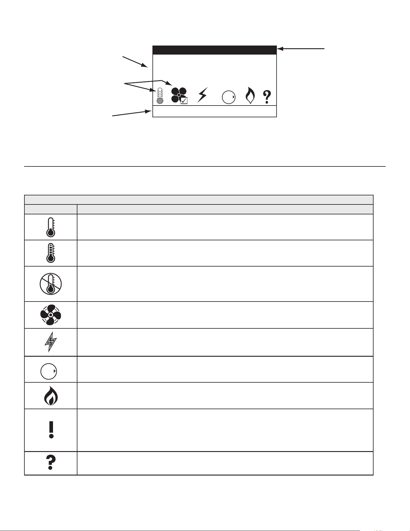
40
LCD Touch Display
Information
Display
Status Icons
Title Bar
Operational menus are
multi functional.
Tank Temperature 103°F
Operating Set Point 120°F
Status: Heating
MENU HELP
GAS
OFF
O
N
Figure 42. User Interface Module - Desktop Screen
STATUS ICONS
Status Icons are displayed on the Desktop screen and convey operational and diagnostic information. Icons are described in the table
below. See Figure 42 (page 40). Ensure the water heater is properly grounded. Flame sensing requires an adequate earth ground. If the
water heater is not properly grounded it will cause Ignition Failure. See Electrical Wiring (page 35).
Table 14. Status Icons
Icon
Description
Water temperature in the tank has fallen. Shaded area of the animated thermometer icon will rise and fall in
response to water temperature in the storage tank as sensed from the Upper and Lower Temperature Probes.
See Features and Components (page 11) for location of Temperature Probes.
Water temperature in the tank has reached the Operating Set Point. The control system enters the Standby mode.
The control is unable to initiate a heating cycle. This will happen whenever a Fault condition is detected by the
control system or when the Enable/Disable switch (located at the base of the water heater) is in disable position.
Note: When the water heater is in disabled mode, a text message appears next to this icon identifying the
reason that it went into disabled mode.
The Combustion Blower is being energized.
The Spark Igniter is being energized. See Spark Igniter (page 14) in Features and Components (page 11) .
GAS
OFF
O
N
The 24 Volt Gas Control Valve is being energized.
The control system has sensed ame at the Main Burner from the ame sensor. See the Sequence Of Operation
Flow Chart (page 54) and Figures 2 &3 in Features and Components (page 11).
The control system has declared a Fault condition and must be inspected/serviced by a Qualied Service Agent.
Fault message details can be viewed in the Current Fault menu. Heating operation is disabled (lock out) until
the condition that caused the Fault is corrected. Power to the water heater must be cycled o and on at the
breaker to reset the control system.
Note: Cycling power will not reset the control system if the condition that caused the Fault has not been corrected.
The control system has declared an Alert condition and must be inspected/serviced by a Qualied Service
Agent. The water heater will continue to operate during an Alert condition.
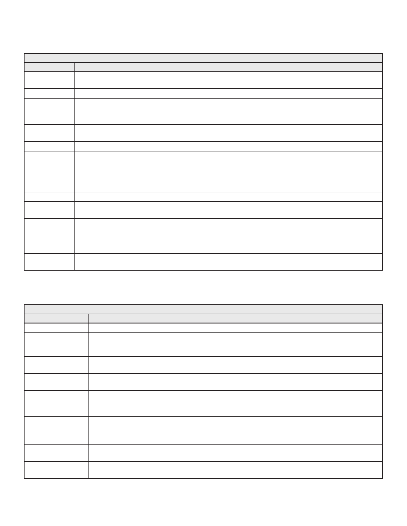
41
OPERATING STATES
The current operational state of the water heater is displayed on the Desktop screen as the Status. The common operational states are
described in the table below.
Table 15. Operating States
State Description
Standby
The water heater is not in an active heating cycle. IE: the Tank Temperature is at or above the Operating Set Point
minus temperature dierential.
Input Verication The control system is conducting a diagnostic check at the beginning of a heating cycle.
Water Heating
Disabled
A Fault condition is detected by the control or when the Enable/Disable switch at the base of the water heater is an
open circuit.
Pre-Purge The Combustion Blower is energized to ush residual ue gases from the combustion chamber prior to ignition.
Spark Igniter
Energized
The Igniter is energized and is ready to ensure proper ignition.
Igniter Activation The 24 Volt Gas Control Valve is energized and opens to allow fuel gas to ow to the Main Burner.
Ignition
Verication
The control System is monitoring the ame sensor for the required minimum ame sensing current. Ensure the water
heater is properly grounded. Flame sensing Requires an adequate earth ground. If the water heater is not properly
grounded it will cause ignition failure.
Inter-Purge
The Combustion Blower is energized to ush residual fuel gas from the combustion chamber after a failed ignition
attempt.
Heating Ignition was successful, ame sensing current has been established. The water in the storage tank is being heated.
Post-Purge
The Combustion Blower is energized to ush residual ue gases from the combustion chamber at the end of a
heating cycle.
Fault
The control system has detected a Fault condition. Heating operation is disabled (control system lock out) until the Fault
condition is corrected. Water Heating Enable/Disable Switch must be cycled o and on to reset the control system.
Note: Cycling Water Heating Enable/Disable Switch will not reset the control system if the condition that caused the
Fault has not been corrected.
Heating
Disabled
The heating is disabled by the Enable/Disable switch located at the base of the water heater.
CONTROL SYSTEM MENUS
From the Desktop screen pressing the Operational button directly
below Menu on the LCD will display the Main Menu. This is where
all control system menus are located. The table below describes the
control system menus.
Table 16. Control System Menus
Menu Description
Temperatures Most commonly accessed menu. Contains the Operating Set Point and Dierential user settings.
Heater Status
This menu displays the current state of all pressure switches and the ECO (open/closed). The on/o status of
the Combustion Blower, 24 Volt Gas Control Valve, Igniter, Flame Sensor and other monitored water heater
components are displayed in this menu.
Display Settings
Temperature units (°F or °C), the LCD appearance (brightness/contrast) and backlight delay user adjustable
settings are located in this menu.
Heater Information
Elapsed time of operation, total heating cycle time, heating cycle count, heating on time along with UIM and
CCB software revisions can be viewed in this menu.
Current Fault Displays any current Alert or Fault messages.
Fault History
This control system menu retains a list of the last nine (9) Fault and Alert messages with a time stamp. The
newest event will replace the oldest. Fault history memory is cleared after 30 days.
Fault Occurrence
This control system menu retains a running total of how many times each Fault condition has occurred since
the water heater was rst installed. This data does not clear and cannot be reset.
Note: If the CCB is replaced during service the fault occurrence historical information for the water heater is lost.
Restore Factory
Defaults
This control system feature allows the user to restore control system user settings to their factory default settings.
Display Settings preferences ARE NOT changed when factory defaults are restored.
Help Screens
Text based operational and user information explaining how to change user settings, navigate the control system
menus and icon descriptions.
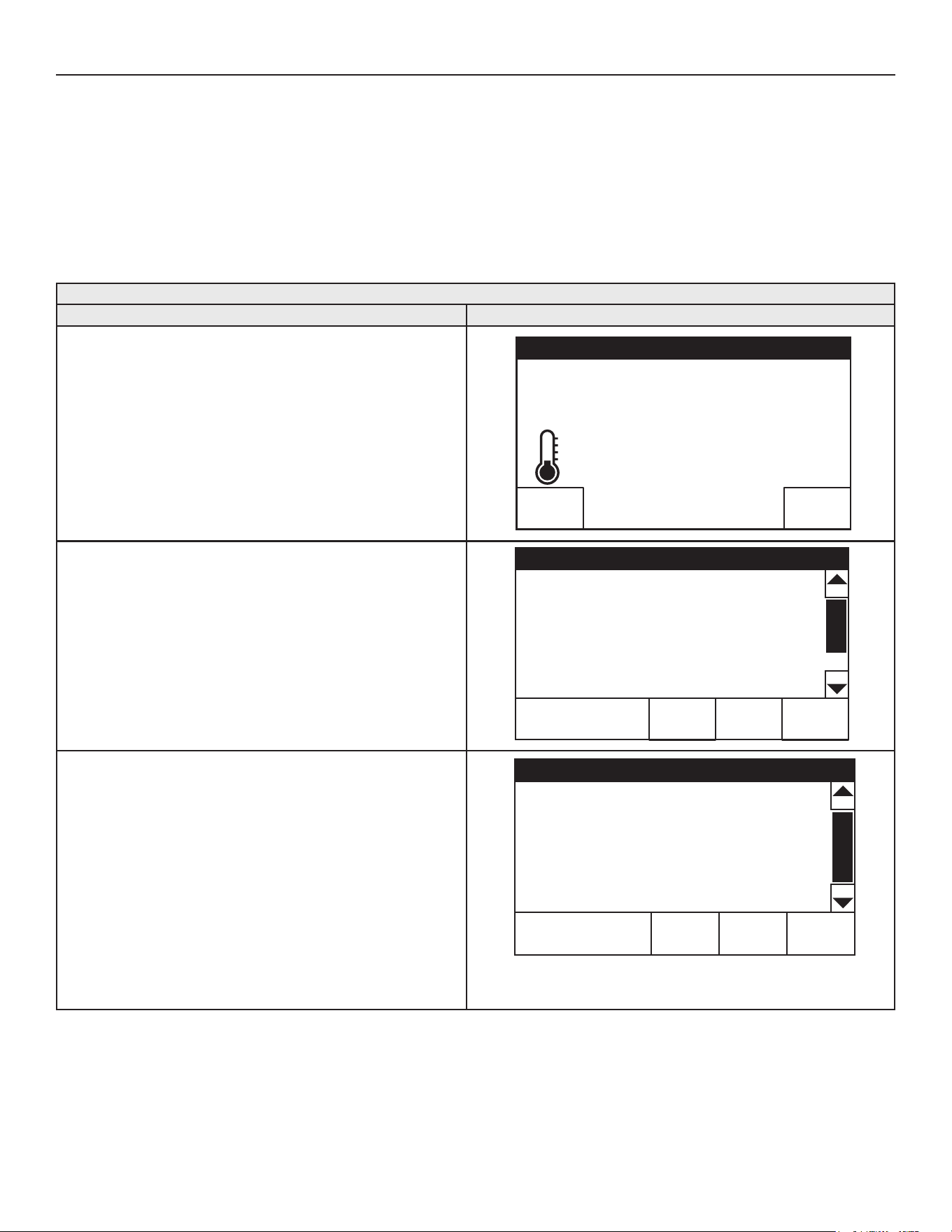
42
USER SETTINGS & CONTROL SYSTEM MENUS
TEMPERATURES MENU
Operating Set Point And Dierential Adjustment
The Operating Set Point is adjustable from 90°F (42°C) to 181°F
(83°C). The factory setting is 120°F (49°C). The Dierential is
adjustable from 2° to 20°F. The factory setting is 8°F. These
user settings are accessed from the Temperatures menu. These
instructions explain how to adjust these settings and navigate the
control system.
When the water temperature sensed by the control system from
the Temperature Probe reaches the Operating Set Point the control
system will end the heating cycle. A heating cycle will be activated
again when the sensed water temperature drops below the Operating
Set Point minus the Dierential setting.
Note: Set the Operating Set Point to the lowest setting which
produces an acceptable hot water supply for most ecient
use. Lower Dierential settings may cause excessive heating
cycles (short-cycling) which can cause premature failure of
components such as the Igniter. Set the Dierential at the
highest setting which produces an acceptable hot water
supply to prevent short cycling.
Temperatures Menu
Description/Action Display
From the Desktop screen, press MENU. The "Main Menu" screen
will be displayed.
Tank Temperature 71°F
Operating Setpoint 120°F
Status: Standby
HELP
MANUFACTURER /MODEL INFORMATION
MENU
The Main Menu is where all control system menus are listed. See
Table 16 (page 41) for a complete list and description of control
system menus. Use the Up and Down slidebar to view all control
system menus from the Main Menu.
Press “Temperatures” to access the Temperature menu.
Main Menu
HELPBACK
Temperatures >
Heater Status >
Display Settings >
Heater Information >
Current Fault >
With the Operating Set Point selected in the Temperatures menu,
press “CHANGE” to activate the adjustment mode for this menu
item.
Press the "Operating Set Point" menu if it is not selected
(highlighted in black).
Note: Higher Temperature settings increase wear and operating
costs. Set the Operating Set Point to the lowest setting
which produces an acceptable hot water supply. This will
always provide the most energy ecient operation and
longer life.
Temperatures
HELPBACK
Operating Setpoint 120°F >
Differential 8°F >
Tank Temperature 120°F
Tank Probe Offset 0°F >
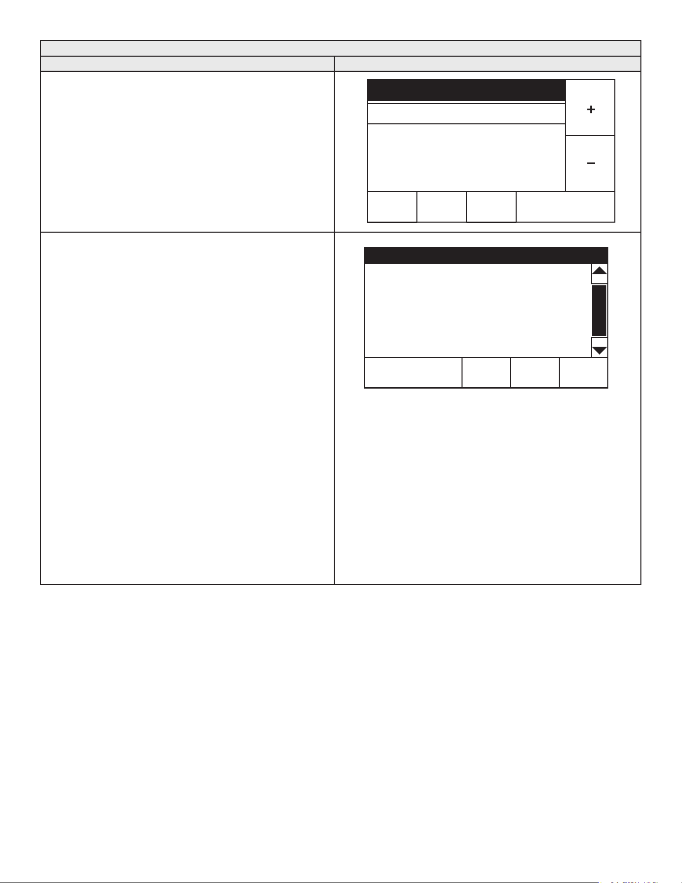
43
Temperatures Menu
Description/Action Display
Use the "+" and "-" Buttons to change the current setting.
Press "ACCEPT" to save the new setting. Press "BACK" to discard
changes and return to the previously saved setting.
Note: Use this same procedure to change the Dierential setting
and other adjustable user settings in the control system
menus.
ACCEPT BACK
Operating Setpoint
MIN
90
°
F
MAX
180
°
F
120
°
F
• Dierential - Adjustable user setting that changes the tank
temperature dierential with a range of 2° to 20°F. The factory
setting is 8°F.
• Tank Temperature - non adjustable - control system sensed
temperature (averaged from upper and lower temperature
probes).
• Tank Probe Oset - adjustable user setting, range -5° to +5°F
(factory setting 0°F).
Note: These settings should only be used if the hot water
supply temperature varies greatly from the Operating
Set Point setting.
The Tank Probe Oset is used to calibrate control system
temperature sensing. This can improve the precision of
temperature control in the storage tank and at points of use.
This feature can also be used to compensate for building
recirculation loops (hot water returning to the storage tank)
that may cause the heating cycles to terminate prematurely.
Example: If the current sensed temperature from a
temperature probe is 120°F (49°C) and the Oset setting is
adjusted to a value other than 0°F, the control system would
calibrate or “oset” the sensed temperature from the probe
and the averaged tank temperature. Heating cycles would
be activated and deactivated based on the calibrated (oset)
temperature. A -5°F setting results in +5°F hotter water.
These settings are adjusted in the same way described for
Operating Set Point And Differential Adjustment (page 42).
Temperatures
HELPBACK
Operating Setpoint 120°F >
Differential 8°F >
Tank Temperature 120°F
Tank Probe Offset 0°F >
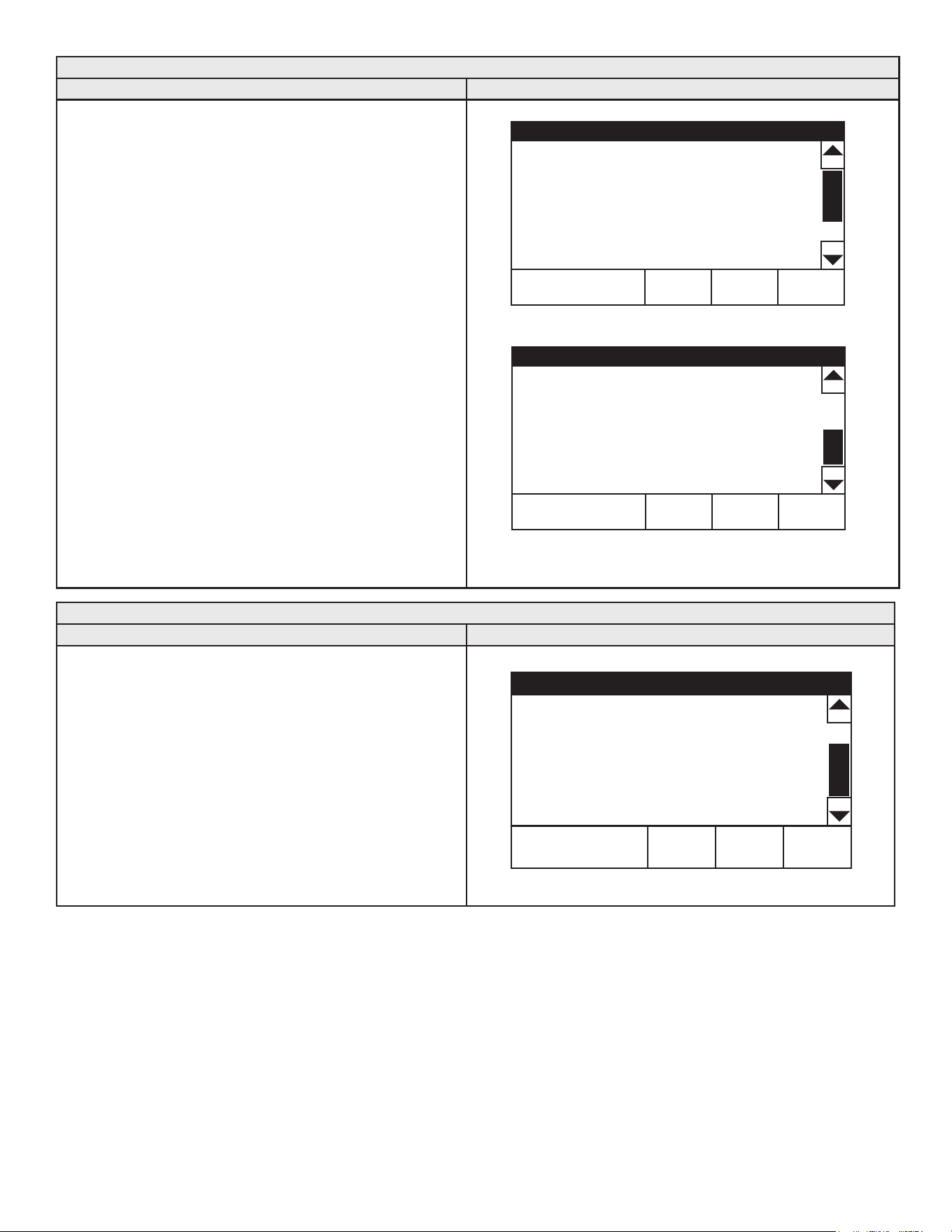
44
Heater Status Menu
Description/Action Display
Press Heater Status from the Main Menu to enter this menu. This
menu contains non adjustable operational information. Use the
slidebar to navigate the menu.
• Status - displays the current Operating State. See Table 15
(page 41).
• ECO Contact, Blocked Inlet PS, Blocked Outlet PS - displays
the current state of the switch contacts; open or closed.
• Igniter On, Gas Valve On - displays whether or not the control
system is currently energizing these water heater components;
yes = energized, no = de-energized.
• Flame Detected - displays whether or not the control system
has detected Main Burner ame during ignition from the ame
sensor.
• Blower RPM CMD - displays the controls commanded blower
RPM.
• Blower RPM - displays the actual blower RPM.
Note: The menu display is shown with the Enable/Disable switch
in Enabled position and the water heater is in Standby
mode. When the Enable/Disable switch is in the Disabled
position, the water heater will be in “Water Heating
Disabled” mode.
Note: The menu displays shown are for informational purposes
only. The actual heater display will vary dependent upon
the operational state of the water heater.
Top of Menu
Heater Status
HELPBACK
Status: Standby
ECO Contact Closed
Blocked Inlet PS Closed
Blocked Outlet PS Closed
Igniter On No
Bottom of Menu
Heater Status
HELPBACK
Gas Valve On No
Flame Detected No
Blower RPM CMD 0
Blower RPM 0
Display Settings
Description/Action Display
Press Display Settings from the Main Menu to enter this menu. This
menu contains adjustable display options for viewing information
on the UIM’s LCD screen. Use the Slidebar to navigate the menu.
• Temperature Units - Adjustable user setting that changes
temperature units display to Celsius °C or Fahrenheit °F.
• Backlight Delay - Adjustable user setting that determines how
long the UIM’s LCD backlight remains illuminated after a key
has been pressed. Available settings are; Always O, 10, 30
or 60 seconds and Always On.
• Contrast - Adjustable user setting to adjust the UIM’s LCD
screen contrast between text and background.
Note: These settings are adjusted in the same way described for
the Operating Set Point And Differential Adjustment (page 42).
Display Settings
HELPBACK
Temperature Units °F >
Brightness 5 >
Backlight Delay 30s >
Language English
>
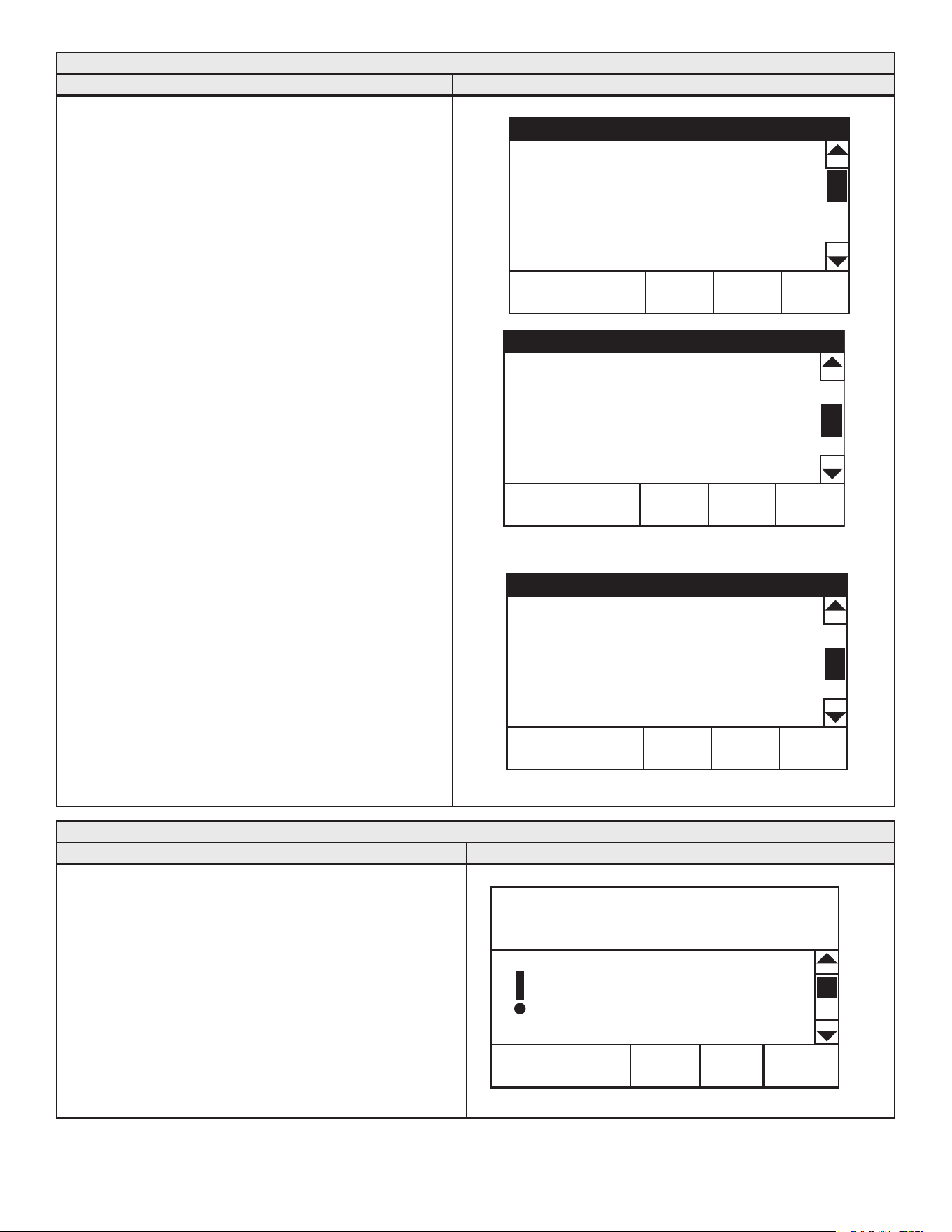
45
Heater Information
Description/Action Display
Press Heater Information from the Main Menu to enter this menu.
This menu contains non adjustable operational information.
• Elapsed Time - Total accumulated time the control system
(water heater) has been energized.
• Burner On Time - Total accumulated time the control system
has been in the heating operating state; burner run time.
• Total Cycle Count - Total accumulated count of heating
cycles.
• CCB Version - Software version for central control board.
• Cong CRC - Veries the conguration key matches the
CCB programming.
• UIM Version - Software version for user interface module.
• Use External Enable - Enables/Disables the external
enable circuit.
• External Enable Status - Displays whether or not the
external enable circuit has been activated.
• Ignition Trials - Displays the number of ignition trials
allowed.
Note: Historical data is stored in the conguration key. If
this "key" is replaced during servicing the historical
data will be lost. The data stored in the new
conguration key will no longer reect the entire
history of the water heater.
The Elapsed Time, Burner On Time and Cycle Count
indicate age, usage and wear.
If the Cycle Count per day is high (divide cycle count by
days to determine cycles per day) or the cycle duration is
short (determine burner on time total minutes, divide burner
on time total minutes by cycle count) consider rasing the
Dierential setting to avoid short cycling and excessive
component wear. See Operating Set Point And Differential
Adjustment (page 42).
This historical data can also be used to assist facilities
managers in forecasting planned replacement of equipment
to help avoid lengthy and costly hot water supply
interruptions.
Top of Menu
Heater Information
HELPBACK
Elapsed Time 0days 0hrs 43mins >
Burner On Time 0days 0hrs 1mins
Use External Enable No >
External Enable Status No >
Ignition Trials 3 tries >
Modulation Enabled >
Heater Information
HELPBACK
Ignition Trials 3 tries >
Modulation Enabled >
Total Cycles Counter 2 >
Ignition Failure Count 1 >
Flame Loss Count 0 >
CCB Version 3.17 >
Bottom of Menu
Heater Information
HELPBACK
Ignition Failure Count 1 >
Flame Loss Count 0 >
CCB Version 3.17 >
Config CRC 0xD7A7 >
UIM Version 2.58 >
Configuration Raw 0x510C >
Current Fault
Description/Action Display
Press Current Fault from the Main Menu and press the Operational
Button under "SELECT" to enter this menu. This menu contains
non adjustable operational information. Use the Slidebar to
navigate the menu.
This menu contains the current Fault or Alert error message. The
time the Fault or Alert message occurred appears directly below.
A brief description of what causes the particular Fault or Alert
condition appears below that. Pressing "ADVANCED" will give
more detailed service information and a list of possible causes
for the Fault or Alert condition. See Fault And Alert Conditions (page
56) for more detailed information and diagnostic procedures.
If there is no Fault or Alert condition active this menu will not
contain any information, "(none)" will be shown next to Current
Fault in the Main menu.
ADVANCEDBACK
0 days 0 hr 0 min ago
Error Code: A8-1201
Blocked Exhaust
Restriction in exhaust pipe.
Check exhaust pipe and
termination for blockage.
Press the Advanced button for
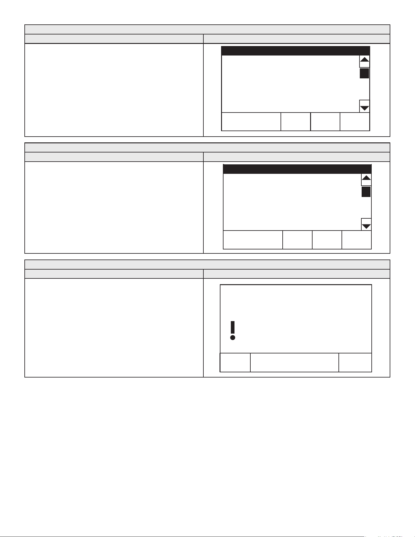
46
Fault History
Description/Action Display
Press "Fault History" from the Main Menu to enter this menu. This
menu contains non adjustable operational information. Use the
Slidebar to navigate the menu.
This menu contains a list of the last nine (9) Fault and Alert
messages with a time stamp. The newest event will replace the
oldest.
Press the Fault to view details for each Fault or Alert message
stored.
Fault History
HELPBACK
1: Upper Temp Probe (Open) (47) >
0 days 2 hrs 37 mins ago >
2: Hardware Failure (1A) >
0 days 2 hrs 37 mins ago >
3: Upper Temp Probe (Open) (47) >
0 days 2 hrs 40 mins ago >
Fault Occurrence
Description/Action Display
Press Fault Occurrence from the Main Menu to enter this menu.
This menu contains non adjustable operational information. Use
the Slidebar to navigate the menu.
This menu contains a running total of how many times each Fault
condition has occurred since the water heater was rst installed.
Note: Historical data is stored in the conguration key. If this "key"
is replaced during servicing the historical data will be lost.
The data stored in the new conguration key will no longer
reect the entire history of the water heater.
Fault Occurrence
HELPBACK
Ignition Failure 0 >
ECO 0
>
Blocked Intake Air 1 >
Blocked Exhaust 1 >
External Input 0 >
Restore Factory Defaults
Description/Action Display
Press Restore Factory Defaults from the Main Menu to enter this
menu.
To restore the adjustable user settings to their factory default
settings press “YES.” The display will show text conrming the
factory default settings have been restored.
Press NO to exit the Restore Factory Defaults menu.
NoYe s
Restore Defaults
Are you sure you want to restore
the system to the factory
defaults?
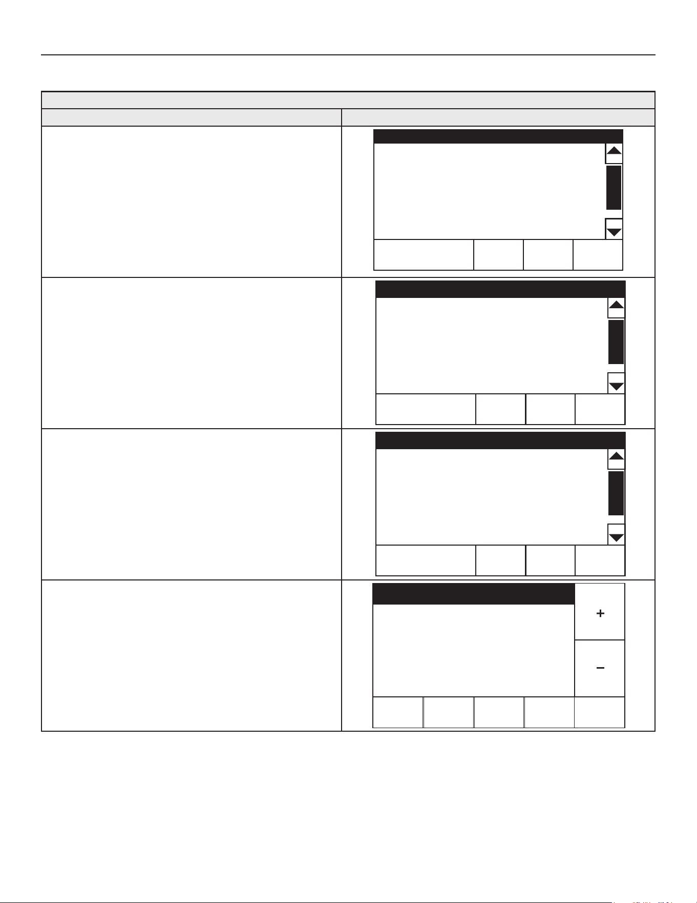
47
SERVICE CONTACT INFORMATION
The control system has a discrete menu that Installing contractors and/or service agents can access to enter contact information for their
customers. This contact information will be displayed with all Fault and Alert messages.
Service Contact Information
Description/Action Display
From the Desktop Screen press and hold down the middle
(unmarked) Operational Button for 30 seconds and then release it.
It is located between the "MENU" and "HELP" buttons. See Figure
42 (page 40).
This will launch a discrete menu where personalized contact
information can be entered.
Using the Slidebar select (highlighted in black) the "Show Contact"
menu item.
Press "ACCEPT" to activate the adjustment mode for this parameter.
Contact Information
HELPBACK
Show Contact No >
Change Contact Name >
Change Contact Phone >
Current Contact Info:
(000) 000-0000
Press the "+" and "-" Buttons to change the setting from "No" to
"Yes" and press "ACCEPT" to save the new setting.
Note: The Access Code at the bottom of the Service Contact
Information screen is for manufacturing engineering purposes
only. There are no user settings or information accessed
through this menu item.
Contact Information
HELPBACK
Show Contact Yes >
Change Contact Name >
Change Contact Phone >
Current Contact Info:
(000) 000-0000
Press the "Change Contact Name" to enter this menu.
Contact Information
HELPBACK
Show Contact Yes >
Change Contact Name >
Change Contact Phone >
Current Contact Info:
(000) 000-0000
Press the "+", "-", "<", and ">" icons to enter your name or the name
of your company.
When nished press "ACCEPT" to save the new Contact Name.
The control system will return to the discrete menu.
Follow these same instructions to change the Contact Phone
Number.
ACCEPT
<
>
>
BACK
Change Contact Name
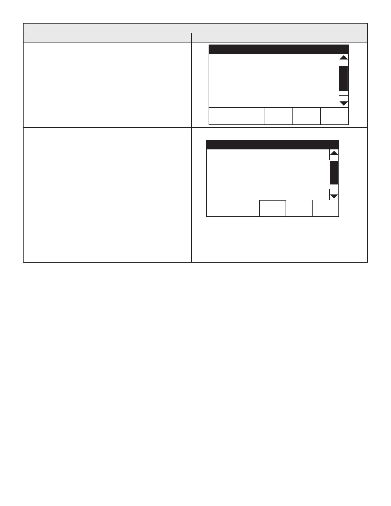
48
Service Contact Information
Description/Action Display
When the new Contact Name and Contact Phone number have
both been updated, press "BACK" to return to the Desktop screen.
Contact Information
HELPBACK
Show Contact Yes >
Change Contact Name >
Change Contact Phone >
Current Contact Info:
YOURCOMPANYNAMEHERE
(123) 456-7890
Access Code - Displays access code utilized to enable/disable
screen lock.
Enable Screen Lock - Factory default set to No. When enabled,
prevents access to any screen but the home screen and the
Contact Information screen. This feature restricts access code to
secure the water heater.
Calibration Mode -Used by service agent to adjust the gas valve for
minimum and maximum re rate.
Calibration Speed - Used by service agents to adjust blower speed
to minimum re rate if required.
Calibration mode will reset back to No when the contact information
screen is exited either by pressing the Back button or when the
display times out. To be practical, the installer/eld service agent
should rst go to the Display Setting screen from the Main Menu
and set the Backlight Delay to 240 (On) before setting Calibration
mode.
Bottom of Menu
Contact Information
HELPBACK
(000) 000-0000
Access Code >
Enable Screen Lock No >
Calibration Mode No >
Calibration Speed Min >
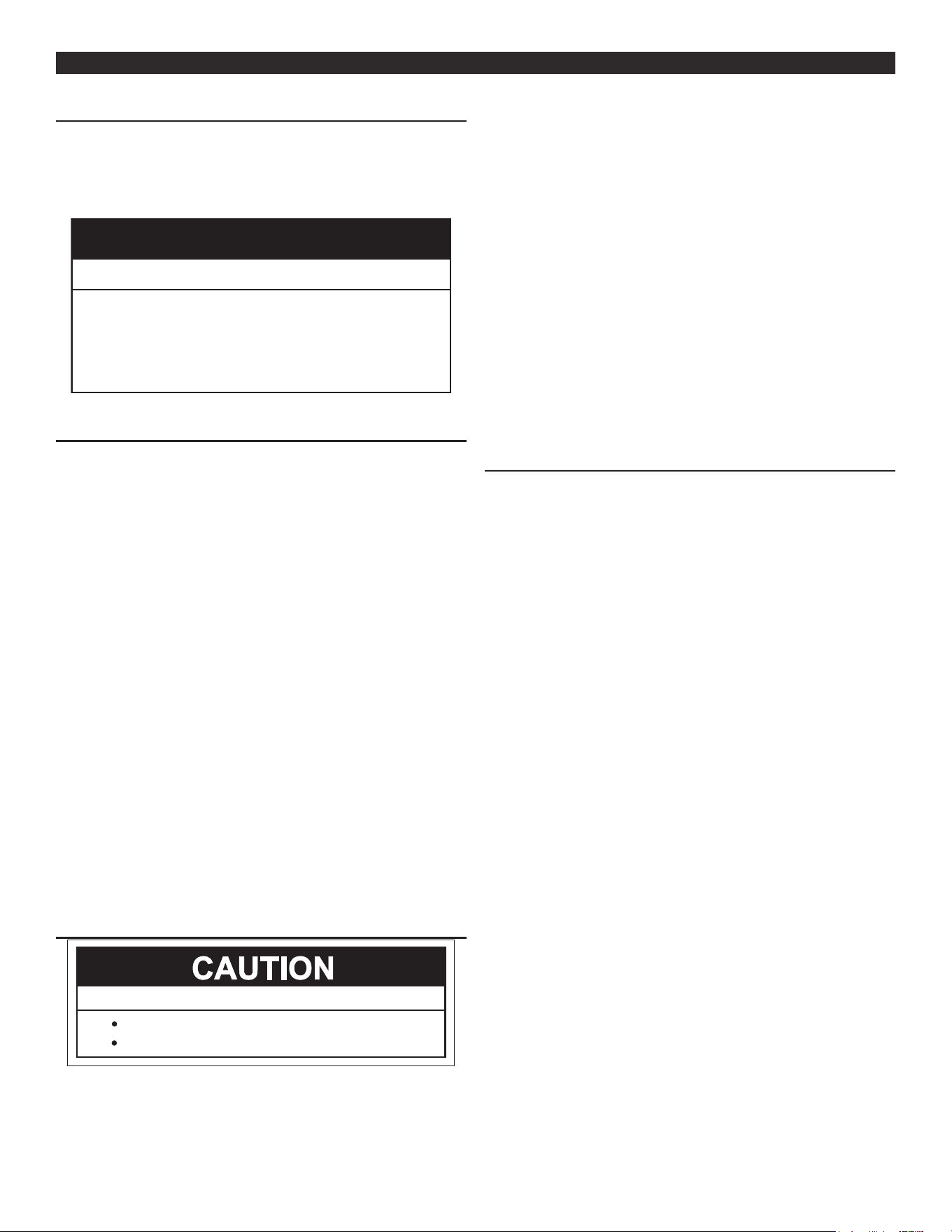
49
START UPSTART UP
START UP CONDITIONS
SMOKE/ODOR
It is not uncommon to experience a small amount of smoke and odor
during the initial start-up. This is due to burning o of oil from metal
parts, and will disappear in a short while.
Property Damage Hazard
● Avoid water heater damage.
● Install thermal expansion tank if necessary.
● Do not apply heat to cold water inlet.
● Contact qualified installer or service agency.
CAUTION
PRIOR TO START UP
Installation and start up of this water heater requires abilities and
skills equivalent to that of a licensed tradesman in the eld involved.
See Qualications (page 8).
DO NOT USE THIS APPLIANCE IF ANY PART HAS BEEN
EXPOSED TO FLOODING OR WATER DAMAGE. Immediately
call a qualied service technician to inspect the water heater and to
make a determination on what steps should be taken next.
Light the water heater in accordance with the Lighting & Operation
Labels on the water heater and in this manual (page 51).
The water heaters covered by this manual are equipped with
an electronic control system, which automatically sequences
the Combustion Blower, pre and post purging of the combustion
chamber, the spark transformer, the 24 Volt Gas Control Valve, Main
Burner Ignition, and ame sensing. The control system will lock
out after three unsuccessful ignition attempts. See Control System
Operation (page 39).
Before attempting start up, thoroughly study and familiarize yourself
with the exact Sequence of Operation. See the Sequence Of Operation
Flow Chart (page 54). Ensure the water heater is properly grounded.
Flame sensing requires an adequate earth ground. If the water heater
is not properly grounded it will cause Ignition Failure. See Electrical
Wiring (page 35).
Be certain that the water heater is full of water, that air is purged
from the gas and water lines and that there are no leaks in the gas
and water lines. Ensure all inlet water valves are open.
FILLING THE WATER HEATER
Avoid water heater damage.
Property Damage Hazard
Fill tank with water before operating.
Never use this water heater unless it is completely full of water.
To prevent damage to the tank, the tank must be lled with water.
Water must ow from the hot water faucet before turning ON gas
to the water heater.
To ll the water heater with water:
1. Locate the drain valve at the base of the water heater behind the
access panel. See Features and Components (page 11).
2. Close the water heater drain valve by turning the handle to the
right (clockwise).
3. Open the cold water supply valve to the water heater.
Note: The cold water supply valve must be left open when the
water heater is in use.
4. To ensure complete lling of the tank, allow air to exit by opening
the nearest hot water faucet. Allow water to run until a constant
ow is obtained. This will let air out of the water heater and piping.
5. Check all water piping and connections for leaks. Repair as
needed. See Gas Line Leak Testing (page 35).
INITIAL START UP
REQUIRED TEST EQUIPMENT
• One U-tube manometer, recommended ranges; 0-14” W.C. (0-3.5
kPa) and 0-35” W.C. (0-8.7 kPa) or pressure gauges.
• One digital manometer can be used in place of U-tube
manometers or pressure gauges. Recommended ranges; -14.00
to +14.00” W.C. (0-3.5 kPa) resolution 0.01” W.C. and 0-35” W.C.
(0-8.7 kPa) resolution 0.10” W.C.
Note: All test equipment must be acclimated to ambient temperature
before calibration and use.
PREPARATION
1. Using the control system menus, change the Operating Set Point
to the lowest temperature setting. See Operating Set Point And
Differential Adjustment (page 42).
2. Turn the water heater’s Enable/Disable switch to the “Disabled”
position.
3. Close the manual gas shut-o valve. See Figure 39 (page 34).
4. Wait ve (5) minutes for any residual gas to clear.
5. Connect the manometer to the supply gas pressure port on the
gas control valve. See Figure 43 and Figure 44 (page 50).
6. On the water heaters covered by this manual there are test ports
for supply and manifold gas pressure readings on the gas control
valve. Using a small at tip pocket screw driver - open the needle
valve inside the supply gas pressure test port one full turn only;
turn the needle valve screw counter-clockwise to open the valve.
Slide the manometer sensing tube over the top of the test port,
see Figure 43 and Figure 44 (page 50).
7. Open the Main Gas Shuto Valve.
8. Measure and record the supply gas pressure, this is a “static”
supply gas pressure reading; while the water heater is not ring.
Adjust supply gas pressure as necessary. See Gas Supply Systems
(page 18).
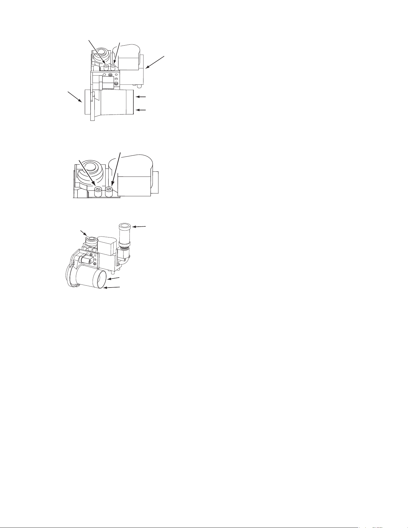
50
MANIFOLD GAS
PRESSURE
TEST PORT
(Non-Adjustable)
SUPPLY GAS
PRESSURE
TEST PORT
GAS CONTROL VALVE / VENTURI ASSEMBLY TOP VIEW
VENTURI
COMBUSTION
AIR INLET
GAS CONTROL
VALVE
COMBUSTION
BLOWER
CONNECTION
Figure 43. Gas Control Valve/Venturi Assembly Top View
MANIFOLD GAS
PRESSURE
TEST PORT
(Non-Adjustable)
SUPPLY GAS
PRESSURE TEST PORT
GAS CONTROL VALVE TOP DETAIL VIEW
Figure 44. Gas Control Valve Top Detail View
GAS CONTROL VALVE / VENTURI ASSEMBLY SIDE VIEW
VENTURI
SUPPLY GAS
CONNECTION
GAS
VALVE
COMBUSTION
AIR INLET
Figure 45. Gas Control Valve/Venturi Assembly Side View
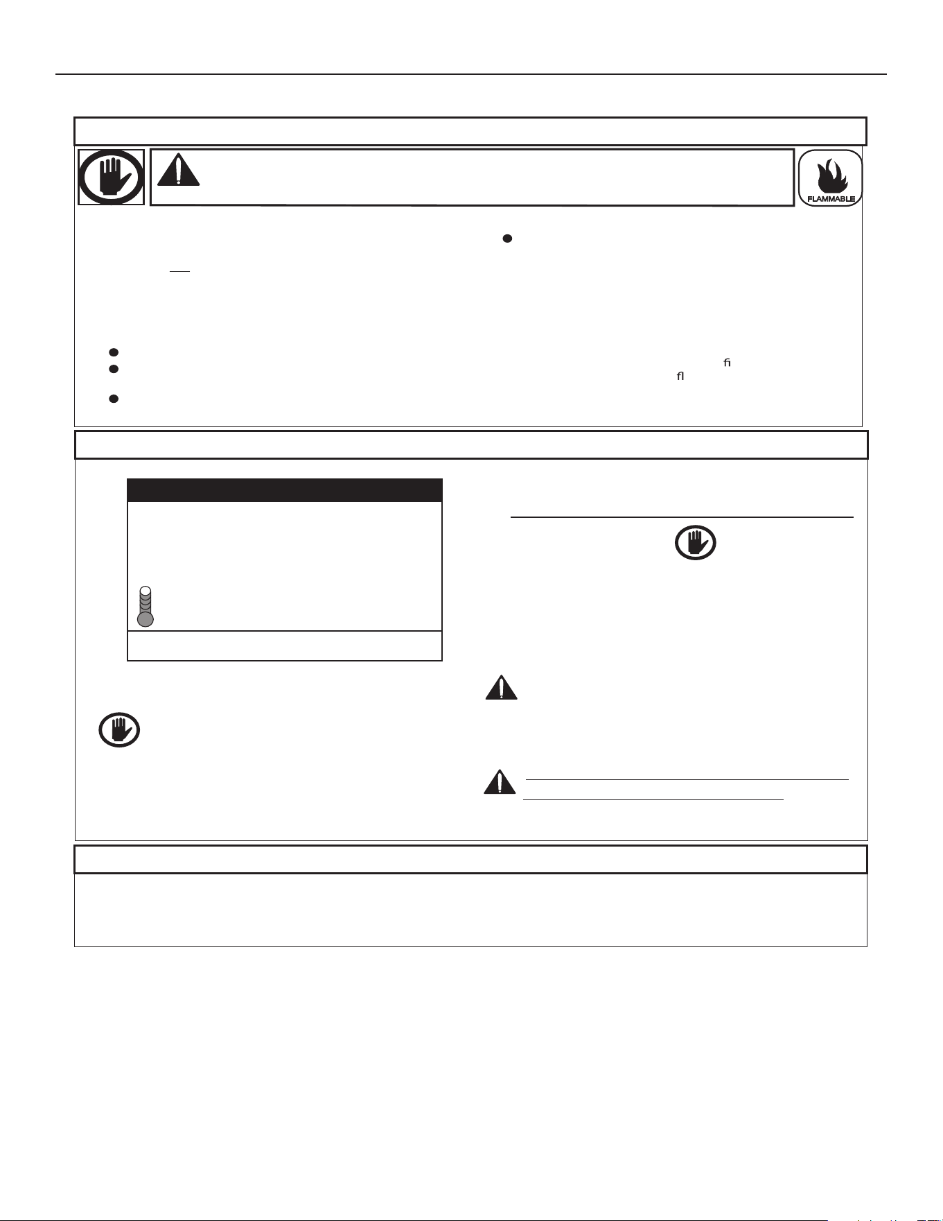
51
LIGHTING & OPERATION LABELS
The instruction label below is axed to the water heater's covered by this manual at the factory and must be followed when lighting and
operating the water heater..
SNOITCURTSNI GNITAREPO
ECNAILPPA OT SAG FFO NRUT OT
ELBAMMALF
FOR YOUR SAFETY READ BEFORE LIGHTING
WARNING:
If you do not follow these instructions exactly, a fire or
explosion may result causing property damage, personal injury
or loss of life.
.1
.1
2. Set the Enable / Disable switch at the base of
the water heater to the Enable position.
4. Set the Enable / Disable switch at the base of
the water heater to the Disable position.
2. Set the Enable / Disable switch at the base of
the water heater to the Disable position.
8. Set the Enable / Disable switch at the base of
the water heater to the Enable position.
3. Set the thermostat to the lowest setting.
!POTS
evobanoitamrofniytefasehtdaeR
.lebalsihtno
.ecnailppaehtotrewoplacirtcelellanonruT
foksirehtsesaercniretawrettoH:NOITUAC
noitcurtsniehttlusnoC.yrujnidlacs
.erutarepmetgnignahcerofeblaunam
CIRTCELELLAFFONRUT:GNINRAW
.GNICIVRESEROFEBREWOP
.5
.6
.7
fiecnailppaehtotrewoplacirtcelellaffonruT
.demrofrepebotsiecivres
.3
.01
ecivedahtiwdeppiuqesiecnailppasihT
.renrubehtsthgilyllacitamotuahcihw
.DNAHYBRENRUBEHTTHGILOTYRTTONOD
-curtsniehtwollof,etarepotonlliwecnailppaehtfI
dna"ECNAILPPAOTSAGFFONRUTOT"snoit
.reilppussagronaicinhcetruoyllac
gnittestsewolehtottatsomrehtehtteS
.
.9
.gnittesderisedehtottatsomrehtehtteS
otsetunim)5(eviftiaW
.sagynatuoraelc
,sagllemsnehtuoyfI
ni"B"wolloF!POTS
uoyfI.lebalsihtnoevobanoitamrofniytefaseht
.petstxenehtotog,sagllemst'nod
.SENILLLAMORFDEGRUPRIADNARETAWHTIWDELLIFEBTSUMMETSYSERITNE:GNITAREPOEROFEB
.A
.B
.C
.D
htiwdeppiuqesitI.tolipaevahtonseodecnailppasihT
ehtsthgilyllacitamotuahcihwecivednoitingina
.renrub .dnahyb
renrubehtthgilotyrttonoD
ecnailppaehtdnuorallallemsGNITAREPOEROFEB
esuacebroolfehtottxenllemsoteruseB.sagrofaera
.roolfehtnoeltteslliwdnarianahtreivaehsisagemos
SAGLLEMSUOYFIODOTTAHW
.ecnailppaynathgilotyrttonoD
s'robhgienamorfreilppussagruoyllacyletaidemmI
.snoitcurtsnis'reilppussagehtwolloF.enohp
ehtllac,reilppussagruoyhcaertonnacuoyfI
.tnemtrapederif
;hctiwscirtceleynahcuottonoD
.gnidliubruoynienohpynaesutonod
ehtnihsupotdnahruoyylnoesU
lortnoc
lortnocehtfI.slootesureveN.snottub
lliwsnottub
llac,mehtriaperotyrtt'nod,nihsupton
detpmettaroecroF.naicinhcetecivresdeifilauqa
.noisolpxeroerifanitluseryamriaper
rednuneebsahtrapynafiecnailppasihtesutonoD
rorellatsnideilauqatcatnocyletaidemmI.retaw
.retaehretawdedooaecalperotycnegaecivres
!decalperebtsumtI.tinuehtriaperottpmettatonoD
Tank Temperature 120°F
Operating Set Point 120°F
Status: Standby
MENU HELP
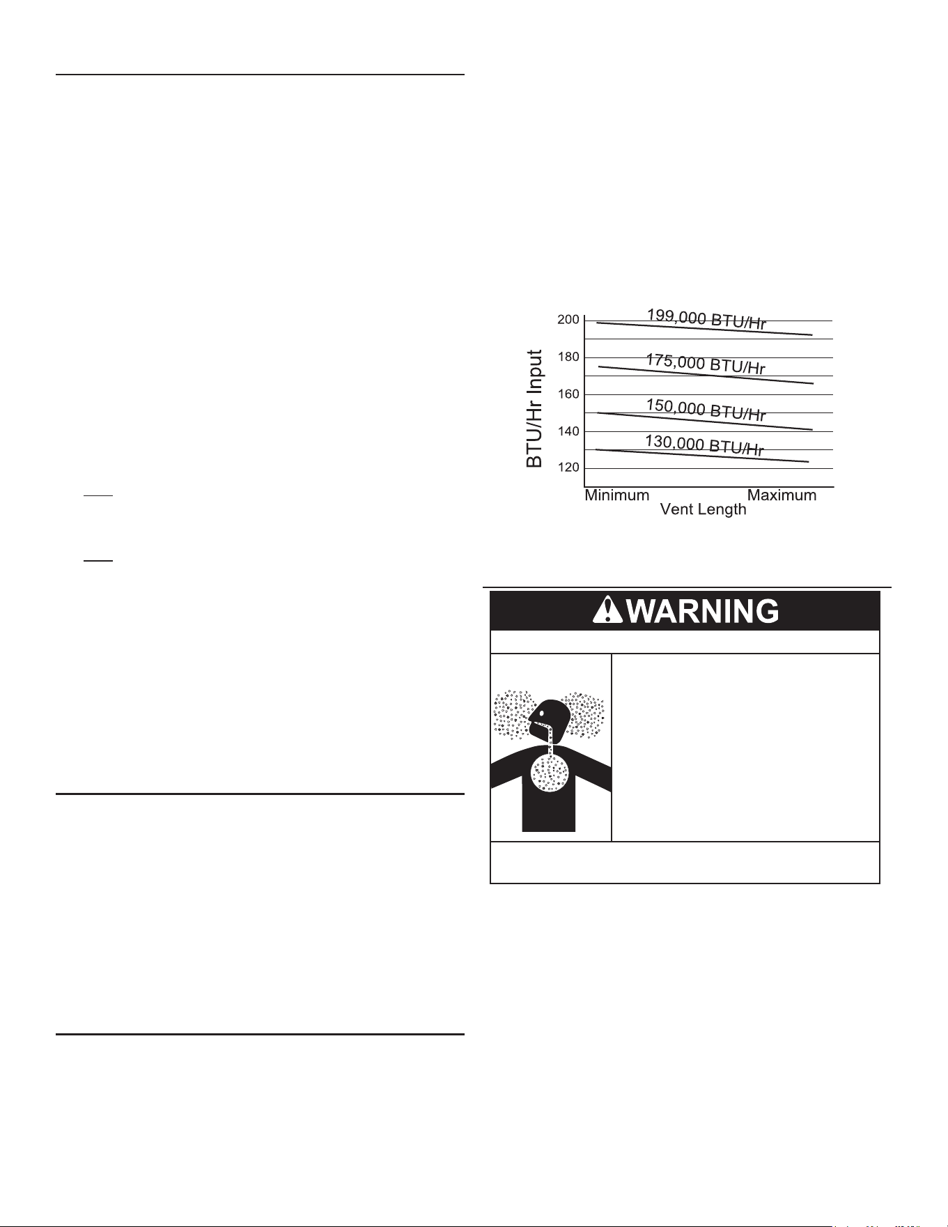
52
CHECKING THE FIRING RATE
Follow these instructions to determine the actual ring rate of the
water heater:
Note: The heaters covered by this manual are capable of modulating
their ring rate. The ring rate should be checked with the
heater operating at it's full ring rate.
1. Ensure there are no other gas red appliances connected to
the gas meter ring during this test.
2. Contact the gas supplier to determine the heating value, in Btu
per cubic foot, of the gas supply.
3. Connect a manometer to the supply gas pressure tap. Follow
the instructions for Start Up (page 49).
4. Start the water heater and ensure it is ring.
5. Check the supply gas pressure, refer to Gas Supply Systems (page
18) for correct pressure.
6. Locate the gas meter serving the water heater.
7. Time how long (in seconds) it takes for one cubic foot of gas
to be used while the water heater is ring with a stop watch.
8. Use the formula below to “clock” the gas meter and determine
the actual ring rate of the water heater based on the heating
value (Btu per cubic foot) of the gas supply:
x H = Btu/hr
3600
T
x 1050 = 300,000 Btu/hr (87.9 kW)
3600
12.6
Example:
• 3600 = seconds in one hour.
• T = time, in seconds, to burn one cubic foot of gas.
• H = heating value of gas in Btu per cubic foot.
• Btu/hr = actual ring rate of the water heater.
Note: 1050 Btu per cubic foot is a standard value for natural gas.
Standard propane gas Btu content is 2500 Btu per cubic foot.
Btu values may change in certain areas and at high elevations.
Check with the local gas utility company.
TO TURN OFF GAS SUPPLY
1. Change the Operating Set Point to the lowest temperature
setting. See Operating Set Point And Differential Adjustment (page
42).
2. When the water heater has completed its shut down sequence
and enters the standby mode, turn the water heater’s Enable/
Disable switch to the “Disable” position. When in the "Disable"
position the switch only removes electrical power from the gas
control valve so that water heating is disabled. The display, CCB,
and other electrical components will still be energized and the
display will read "Water Heating Disabled".
3. Close Main Gas Shuto Valve. See Figure 39 (page 34).
GAS INPUT RATE
The gas input rate of this water heater is aected by several
environmental factors such as:
• The heating value of the gas
• The air and gas densities (which vary widely due to barometric
pressure and temperature changes)
• Venting installations (pipe diameter, length and ttings)
• Altitude
When measuring the input rate these factors should be incorporated
into the calculations. Also measure the gas consumption over a
suciently long time to obtain an accurate gas consumption rate
(e.g. 3-5 minutes, not one revolution of the meter needle).
Long vents and each additional elbow, inherently reduce the gas
input rate due to increased resistance to moving combustion air and
ue gases. The approximate maximum/minimum input for all PGC,
SPC, BSS, and BTS models is show in Figure 46.
Figure 46. BTU/Hr Input by Vent Length
HIGH ALTITUDE INSTALLATIONS
Breathing carbon monoxide can cause brain damage or death.
Always read and understand the instruction manual.
Special considerations must be taken with
installations above 7,700 feet (2,347 m).
Please contact an A. O. Smith qualified
service agent to obtain the proper setupt
and instructions before lighting.
Breathing Hazard - Carbon Monoxide Gas
•
Failure to implement the proper setup will
result in improper and inefficient operation
of the appliance, resulting in production of
increased levels of carbon monoxide gas
in excess of the safe limits which could
result in serious personal injury or death
.
•
•
This high efficiency water heater is certified for use without
modication for an altitude of 7,700 feet (2,347 m). Consult the factory
for installation at altitudes over 7,700 feet (2,347 m).
Some gas utility companies derate their gas for altitude, making
it unnecessary to install high altitude orices. Call the local gas or
utility company to verify BTU content.
Due to the input rate reduction at high altitudes, the output rating of
the water heater is also reduced and should be compensated for in
the sizing of the equipment for applications. See Planning The Vent
System (page 25).

53
TROUBLESHOOTINGTROUBLESHOOTING
INSTALLATION CHECKLIST
The list below represents some of the most critical installation
requirements that, when overlooked, often result in operational
problems, down time and needless parts replacement. This is not
a complete list. Before performing any troubleshooting procedures
use the list below to check for installation errors. Costs to correct
installation errors are not covered under the limited warranty. Ensure
all installation requirements and instructions in this manual have
been maintained and followed.
WATER HEATER LOCATION
1. Ensure proper clearances to combustibles are maintained and
there is sucient room to service the water heater. See Locating
the Water Heater (page 15).
2. Ensure the area is free of corrosive elements and ammable
materials. See Combustion Air And Ventilation (page 16).
VENTING
3. Ensure the intake air and/or vent (exhaust) piping is the correct
size for the installed length. See Vent Pipe Installation (page 24).
4. Ensure the maximum equivalent feet of pipe has not been
exceeded for the intake air and/or vent pipe. See Vent Pipe
Installation (page 24).
5. Ensure the maximum number of elbows has not been exceeded
in the intake air and/or vent pipe. See Vent Pipe Installation (page
24).
6. Ensure all exterior clearances for the intake air, vent and
concentric terminations are maintained. These clearances and
those cited by local and national codes must be maintained. See
Horizontal Vent Terminal Installation (page 27), Vertical Vent Terminal
Installation (page 27), and Concentric Vent Installation (page 31).
7. Ensure the integrated lter in air intake at the water heater is clean
and free of debris. See Integrated Filter Preventative Maintenance
(page 59).
GAS SUPPLY AND PIPING
8. Ensure a supply gas regulator has been installed for each water
heater. See Supply Gas Regulator (page 18).
9. Ensure the supply gas line to each water heater meets the
minimum supply gas line size requirements. See Gas Supply
Systems (page 18) and Supply Gas Line Installation (page 33).
CONDENSATE DRAIN
10. Ensure the condensate drain is properly connected to the exhaust
elbow on the water heater and draining freely to a suitable oor
drain. See Condensate Drain Installation (page 33).
ELECTRICAL CONNECTIONS
11. Ensure the power supply connections to the water heater are
polarity correct. See the requirements for the Power Supply (page
18) and Electrical Wiring (page 35).
12. Ensure the water heater is properly grounded. Flame sensing
requires an adequate earth ground. If the water heater is not
properly grounded it will cause Ignition Failure. See Electrical
Wiring (page 35).
SEQUENCE OF OPERATION
Read the Sequence of Operation below before attempting to correct
any operational problems. Refer to the Features and Components (page
11) for the location of various water heater components described
below. Also, see the Sequence Of Operation Flow Chart (page 54).
1. When the control system is rst powered, during boot up, the
blower will run momentarily and stop, and the control system will
display water heater model information during initialization. After
a few moments the control system LCD which is part of the UIM
(user interface module) will display the default screen known as
the Desktop screen.
2. If the control system determines that the actual water temperature
inside the tank is below the programmed Operating Set Point
minus the Dierential setting, a heating cycle is activated.
3. The control system then performs selected diagnostic system
checks. This includes conrming the blocked exhaust, blocked
intake and ECO (energy cut out) switch contacts are closed.
4. If all diagnostic checks are successfully passed, the control
system energizes the Combustion Blower for pre-purge.
5. The control system energizes the Spark Ignition Transformer.
6. After a few seconds, the control system energizes the 24V Gas
Control Valve allowing gas to ow to the Main Burner.
7. The control system monitors the ame sensor to conrm a ame
is present at the Main Burner. If a ame is not veried during the
ignition trial period the control system will try for ignition up to
two more times. If ame can not be veried after three trials for
ignition, the control system will lock out and display the Ignition
Failure Fault message.
8. If a ame is veried, the control system will enter the heating
mode where it will continue heating the water until the Operating
Set Point is reached. At this point, the control system will de-
energize the 24 V Gas Control Valve and enter the post-purge
cycle (approximately 30 seconds).
9. The water heaters covered by this manual are capable of
modulating their ring rate. The ring rate is dictated by the hot
water draw and various other temperature limitations.
10. The Combustion Blower will run for the duration of the post-purge
cycle to purge the water heater of all combustion gases. When
the post-purge cycle is complete, the blower is de-energized and
will coast to a stop.
11. The control system now enters the standby mode while continuing
to monitor the internal storage tank water temperature and the
state of other system devices. If the tank temperature drops below
the Operating Set Point minus the Dierential setting, the control
will automatically return to Step 2 and repeat the operating cycle.
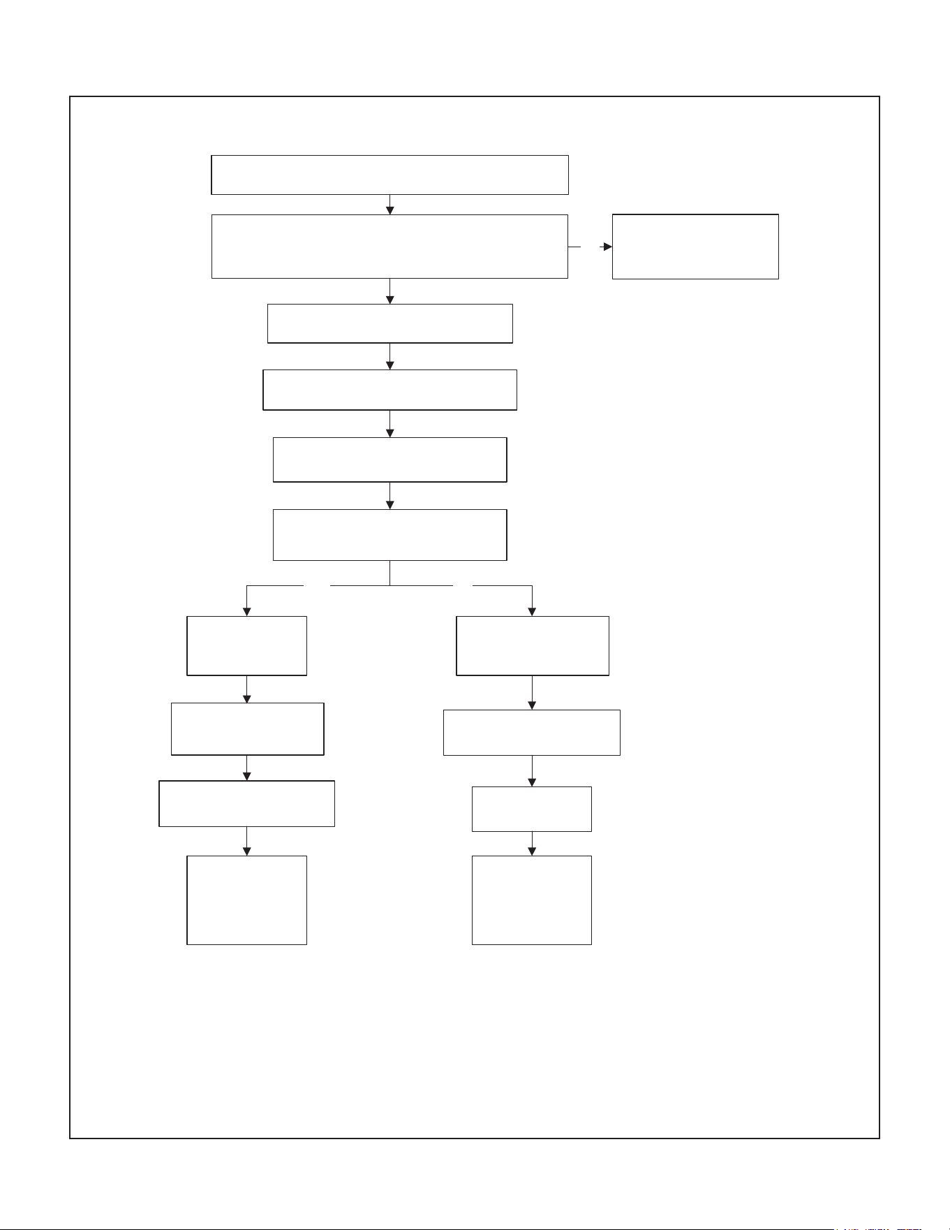
54
SEQUENCE OF OPERATION FLOW CHART
YES NO
Water is heated to
set point
60 second Inter-Purge cycle
Retries up to
two more times
60 second Post Purge cycle
Control System
Locks Out
“Ignition Failure”
Fault Msg is
displayed
Water heater goes
into standby mode
If tank temperature drops below Operating Set Point minus
Differential setting a heating cycle is activated
Igniter is energized
24 V Gas Control Valve is energized
gas flows to Main Burner
24 V Gas Control Valve
de-energized
24 V Gas Control Valve
de-energized
Is flame sensed at the Main Burner?
(control system monitors the flame sensor)
Control System Locks Out
Displays Fault Msg
NO
Combustion Blower is energized
30 Second Pre-Purge cycle
Control System performs diagnostic checks
Normal State of all pressure switches and ECO are checked
Pressure Switches and ECO are verified closed
Figure 47. Sequence of Operation
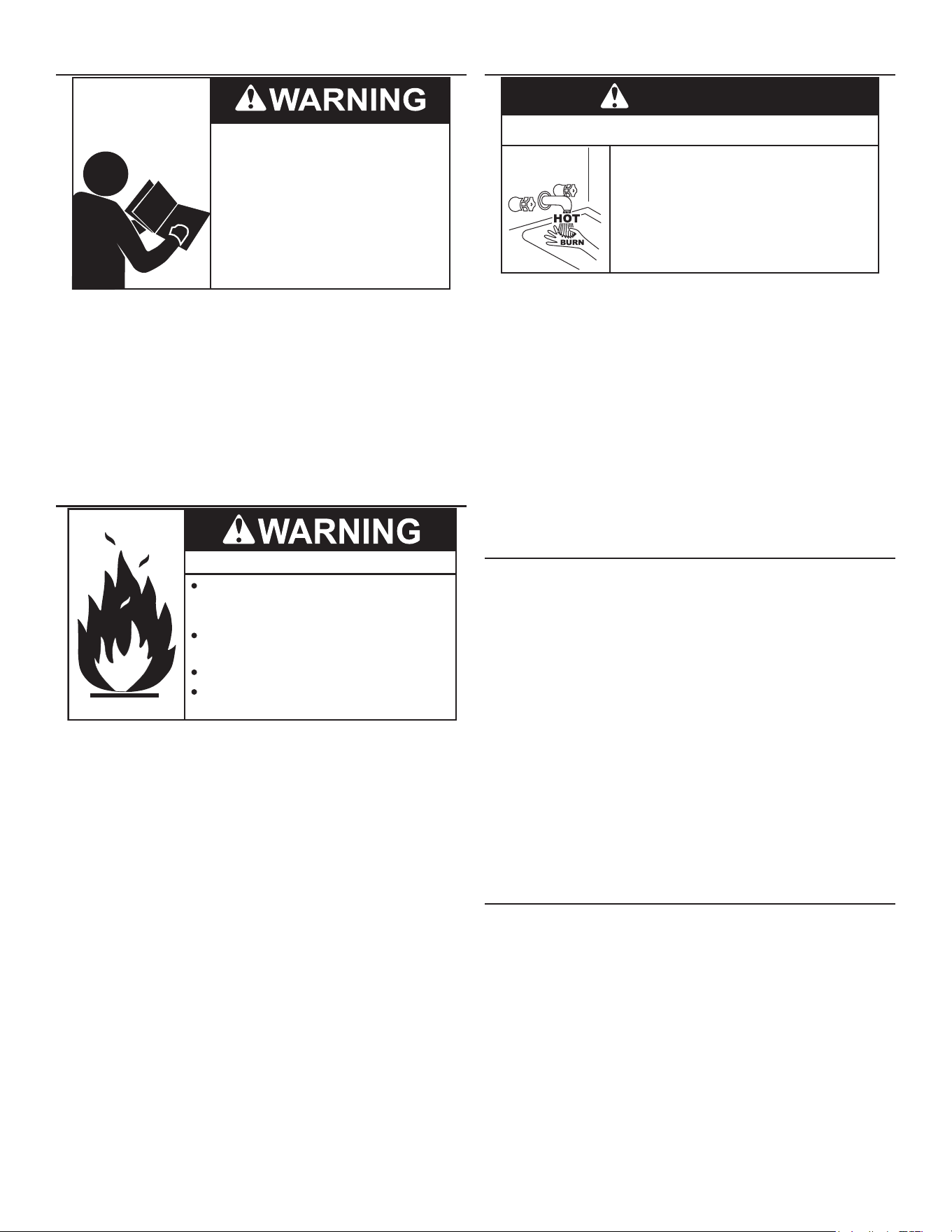
55
OPERATIONAL PROBLEMS
Read and understand this instruction
manual and the safety messages
herein before installing, operating or
servicing this water heater.
Failure to follow these instructions and
safety messages could result in death
or serious injury.
This manual must remain with the
water heater.
This section of the manual is intended to be an aid in correcting
common operational problems, it is not all inclusive. The installer
may be able to observe and correct certain problems which might
arise when the water heater is rst put into operation or when it is
re-red after a prolonged shutdown. However, only qualied service
technician should perform any service procedures on the water
heater.
Note: Call the technical support phone number listed on the back
cover of this manual for further technical assistance or to
locate a qualied service technician in your area.
ROUGH STARTING, ROUGH OPERATION
Fire and Explosion Hazard
Turn off gas lines during installation.
Contact a qualified installer or service
agency for installation and service.
Excessive gas pressure to gas valve can
cause serious injury or death.
Do not use water heater with any gas
other than the gas shown on the rating
label.
• Undersized supply gas line (low volume of supply gas).
• Low Gas Pressure.
• Excessive supply gas pressure.
• Excessive manifold (oset) gas pressure.
• Incorrect Fuel Type
• Vent (exhaust) gas recirculation at the vent and intake air pipe
terminations on Direct Vent installations.
• Excessive equivalent lengths of intake air and/or vent (exhaust)
piping installed.
• Clogged/blocked air intake integrated lter.
• Clogged/blocked the Main Burner.
MOMENTARY IGNITION
Burn Hazard
Do not reach into the burner housing or
combustion chamber if the water heater
is still hot.
•
Allow the water heater to cool and always use
gloves when handling the main burner.
•
•
The combustion chamber and burner sleeve
and housing become very hot during operation.
CAUTION
If the Main Burner ignites momentarily but does not sustain ignition
allow the water heater to try to ignite up to two more times until
control system locks out and the Ignition Failure Fault message
is displayed on the control system's LCD. If the water heater is
experiencing rough starts - see Rough Starting, Rough Operation on
this page. For momentary ignition problems without rough starting
check the following:
• Undersized supply gas line (low volume of supply gas).
• Low Gas Pressure
• See the list of possible causes and things to check and repair
for the Ignition Failure Fault message.
• Clogged/blocked air intake integrated lter.
• Clogged/blocked Main Burner.
NOT ENOUGH OR NO HOT WATER
• No power to the water heater, check breaker, fuses.
• Enable/Disable switch in “disabled” position. Set to enable to
allow unit to operate.
• Hot water supply valve(s) to xtures closed.
• Operating Set Point is set too low, Dierential setting is set too
high.
• Temperature Probe Oset setting are causing the heating cycles
to terminate prematurely.
• The heating capacity of the water heater has been exceeded,
the water heater is unable to meet demand.
• Colder incoming water temperature lengthening the time required
to heat water to desired temperature.
• Hot water piping leaks, open faucets, water heater drain valve
leaking or open. See Leakage Checkpoints (page 58).
• Sediment or lime scale accumulation may be aecting water
heater operation.
WATER IS TOO HOT
• Operating Set Point is set too high. See Operating Set Point And
Differential Adjustment (page 42).
• Temperature Probe Oset settings improperly set. See Operating
Set Point And Differential Adjustment (page 42).
• If installed check Thermostatic Mixing Valve settings. See Mixing
Valves (page 19).
• Lime build-up on temperature probes.
NOISY OPERATION
• Normal operating noise of electrical components; Combustion
Blower, transformer hum, relay contact closure.
56
REPLACEMENT PARTS
Replacement parts may be ordered from the manufacturer,
authorized service agencies or distributors. When ordering parts
be sure to have the complete water heater Model Number, Serial
Number and Series Number available. This information can be found
on the rating plate axed to the water heater.
For more information or technical support call the technical support
phone number listed on the back cover of this manual.
FAULT AND ALERT CONDITIONS
FAULT CONDITIONS
When the control system declares a Fault condition it will display a
Fault message on the control system's LCD with an exclamation "!"
mark. The control system will lock out and disable heating operation
until the condition is corrected. The water heater must be serviced
by a qualied service technician before operation can be restored.
ALERT CONDITIONS
When the control system declares an Alert condition it will display an
Alert message on the control system's LCD with a question "?" mark.
The water heater will continue to operate during an Alert condition but
the water heater must be serviced by a qualied service technician
as soon as possible.
RESETTING CONTROL SYSTEM LOCK OUTS
To reset the control system from a lock out condition; turn the Enable/
Disable switch at the base of the unit to the “Disable” position for
approximately 20 seconds and then back to the “Enable” position.
Keep in mind: if the condition that caused the Fault has not been
corrected, the control system will continue to lock out.
DIAGNOSTIC CHECKS
Turn off power at the branch circuit
breaker serving the water heater
before performing any service.
Electrical Shock Hazard
•
Label all wires prior to disconnecting
when performing service. Wiring errors
can cause improper and dangerous
operation.
•
Verify proper operation after servicing.
•
Failure to follow these instructions can
result in personal injury or death.
•
The following section, Fault And Alert Messages lists some of the
messages the control system will display on the LCD when there
are operational problems. This is not a complete list. Along with
each of the Fault and Alert messages described there will be a list
of possible causes and things to check and repair.
Only qualied service technician, as dened in Qualications (page
8) using appropriate test equipment, should perform any service
procedures on the water heater.
Note: If you are not qualied and licensed or certied as required
by the authority having jurisdiction to perform a given task
do not attempt to perform any of the diagnostic or service
procedures described in the following section.
If you do not understand the instructions in the following section do
not attempt to perform any procedures.
Call the technical support phone number listed on the back cover of
this manual for further technical assistance or to locate a qualied
service technician in your area.
Jumping out control circuits or components can
result in property damage, personal injury or death.
Service should only be performed by a qualified service
technician using proper test equipment.
•
Altering the water heater controls and/or wiring in any way
could result in permanent damage to the controls or water
heater and is not covered under the limited warranty.
•
Any bypass or alteration of the water
heater controls and/or wiring will result
in voiding the appliance warranty.
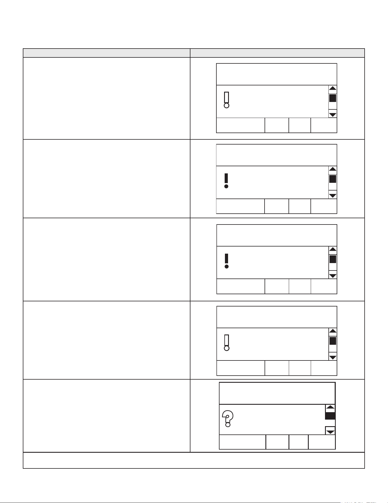
57
FAULT AND ALERT MESSAGES
Call the technical support phone number listed on the back cover for further technical assistance or to locate a qualied service technician
in your area.
Possible Causes - Check/Repair Displayed Fault/Alert Message
• Using a manometer, ensure that gas supply pressure is above
minimum requirement listed on heater’s data plate and does
not drop more than 1.5” W.C. when unit res.
• Ensure wire connections to gas control valve are clean and
tight.
• Ensure wire connections to ame sensor are clean and tight.
• Ensure wire connections to spark igniter are clean and tight.
• Inspect ame sensor, clean/replace as needed.
• Inspect spark igniter, realign igniter gap as needed
• Ensure adequate electrical ground to heater.
ADVANCEDBACK
0 days 0 hrs 0 mins ago
Error Code: B2-70
Ignition Failure
Flame not detcted. Clean flame
rod. Check gas supply.
Press the Advanced button for
more information
• If Blocked Exhaust error occurs when blower is running, check
for restrictions in exhaust pipe, including exhaust elbow,
condensate drain, and outside termination. Also check exhaust
pipe installation (size/length) per manual.
• If Blocked Exhaust error occurs before blower runs, make
sure pressure switch connections are clean and tight. Check
pressure switch continuity/resistance. Switch should be closed
(continuity/0 ohms). Replace switch if open (no continuity).
• High wind conditions may be another possible cause.
ADVANCEDBACK
0 days 0 hr 0 min ago
Error Code: A8-1201
Blocked Exhaust
Restriction in exhaust pipe.
Check exhaust pipe and
termination for blockage.
Press the Advanced button for
• If Blocked Intake error occurs before blower runs, make sure
pressure switch connections are clean and tight.
• If Blocked Intake error occurs when blower is running, check
for restrictions in intake pipe, including intake air connection,
intake air lter, outside termination, and inlet moisture drains.
• Other possible causes: High wind conditions, excessive
negative air pressure in building.
• Use a multi-meter to check the continuity / resistance of inlet air
pressure switch. Switch should be open (no continuity) when
the blower is o and closed (shorted) when the blower is on.
Replace the switch if necessary.
ADVANCEDBACK
0 days 0 hrs 0 mins ago
Error Code: A7-1201
Blocked Air Intake
Restriction in air intake.
Check intake pipe and
termination for blockage.
Press the Advanced button for
• Ensure wire connections to upper temperature probe are clean
and tight.
• Using a thermometer, check the water temperature of the
heater.
• Use a multi-meter and check for continuity between the two
red wires of the upper temperature probe.
• If the two red wires are open (no continuity) and water
temperature is below 160°F, replace upper temperature probe.
• If the water temperature exceeds 195°F, turn o electric power
and gas supply and call Tech Support for further instructions.
ADVANCEDBACK
0 days 0 hrs 0 mins ago
Error Code: A5 - 401
High Temp Limit Exceeded
Energy Cut Off has shut off
water heater due to high tank
temperature.
Press the Advanced button for
• Conrm that the lower probe cable is plugged into the CCB
and the lower probe connector.
• Measure resistance of probe to check for an open or shorted
circuit.
• Inspect lower probe cable for damage.
• Inspect the lower probe. Replace as needed.
ADVANCEDBACK
Lo wer Te m p Pro be (Open)
0 days 0 hrs 0 mins ago
Error Code: 48-
0
The indicated temperature Probe
may be shorted or open. Check
connector and resistance of
Probe.
Call the technical support phone number listed on the back cover for further technical assistance or to locate a qualied service technician
in your area.
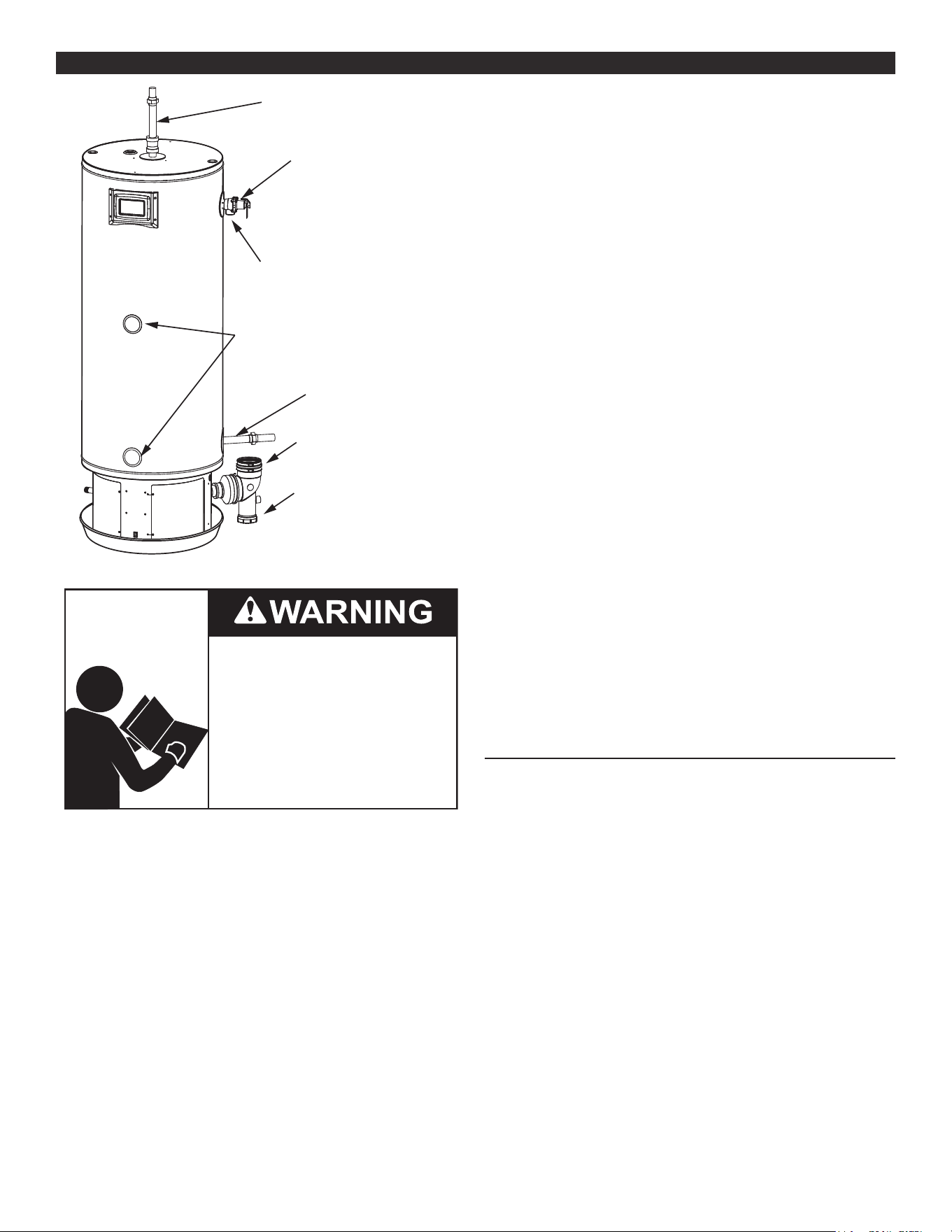
58
LEAKAGE CHECKPOINTSLEAKAGE CHECKPOINTS
A. Hot Water Outlet
E. Cold Water Inlet
B. T&P Connection
C. T&P Outlet
D. Temperature
Probe Connections
I. Exhaust Outlet
J. Condensate
Clean-Out Cap
Figure 48. Leakage Checkpoints
Read and understand this instruction
manual and the safety messages
herein before installing, operating or
servicing this water heater.
Failure to follow these instructions and
safety messages could result in death
or serious injury.
This manual must remain with the
water heater.
Never use this water heater unless it is completely lled with water.
To prevent damage to the tank, the tank must be lled with water.
Water must ow from the hot water faucet before turning “ON” gas
to the water heater.
A *Condensation may be seen on the hot water outlet pipe in
humid weather or the hot water outlet connection may be
leaking.
B. *Condensation may be seen on the cold water inlet pipe in
humid weather or the cold water inlet connection may be
leaking.
C. Small amounts of water from temperature-pressure relief valve
may be due to thermal expansion or high water pressure in
your area.
D. *The temperature-pressure relief valve may be leaking at the
tank tting.
E. Water from a drain valve may be due to the valve being slightly
opened. (Not shown in Figure 48).
F. *The drain valve may be leaking at the tank tting. (Not shown
in Figure 48).
G. Leakage from recirculation plug or pipe connection. (Not
shown in Figure 48.
H. Leakage from the temperature probe connections.
I. Condensate from the exhaust connection.
J. Condensate Clean Out Cap
Leakage from other water heaters, water lines, or ground seepage
should also be checked.
* To check where threaded portion enters tank, insert cotton
swab between jacket opening and tting. If cotton is wet,
follow the draining instructions in Draining and Flushing (page
60) and then remove the tting. Put pipe dope or teon
tape on the threads and replace. Then, follow the instructions
in Filling The Water Heater (page 49).
WATER LEAK DETECTION
The water heaters covered by this manual have a water leak
detection feature that senses the buildup of water in vicinity of the
appliance, setting o an alarm to alert the end user.
To use this feature, you must install a kit. To obtain the appropriate kit,
contact your local distributor or call Technical Support for assistance.
Kit number 100302557
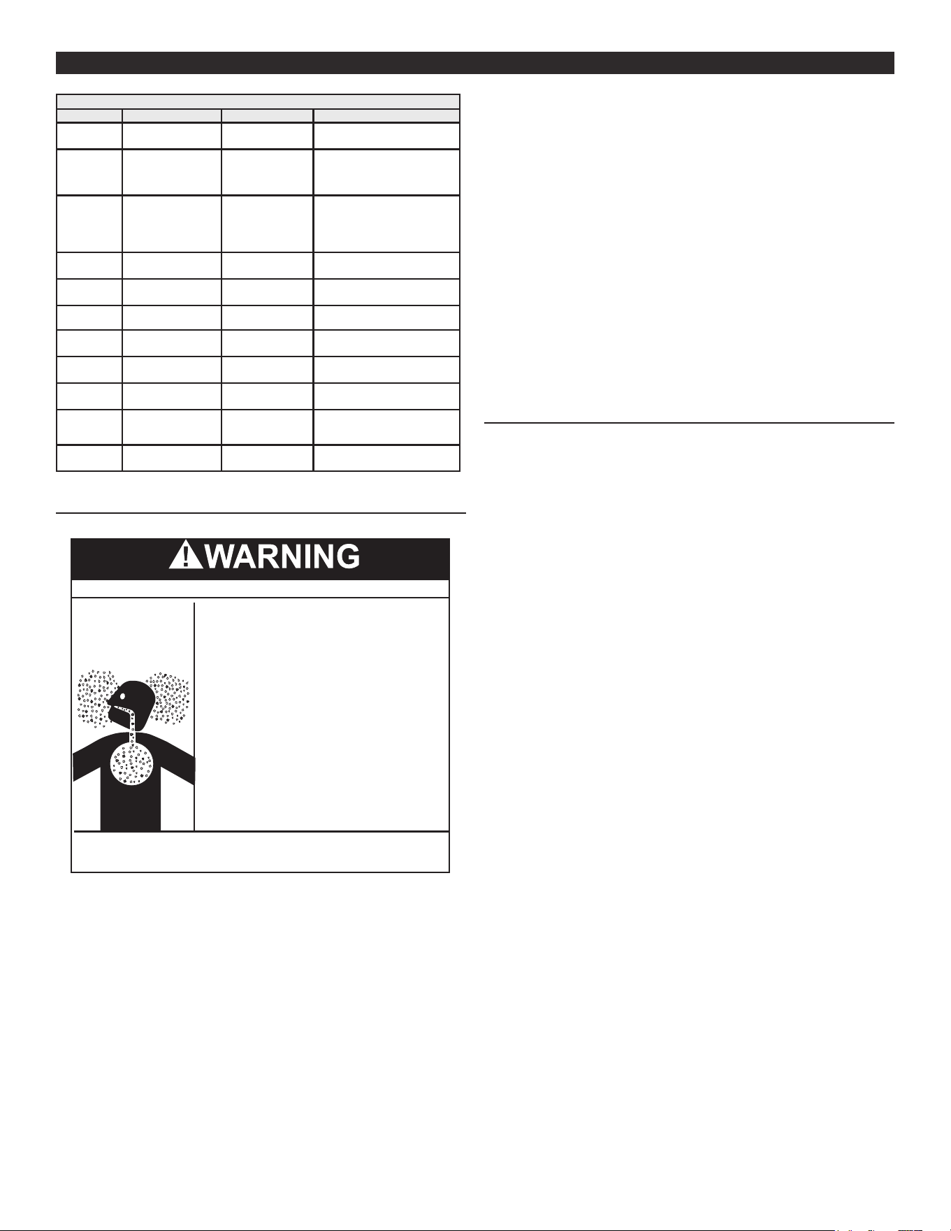
59
PERIODIC MAINTENANCEPERIODIC MAINTENANCE
Table 17. Maintenance Schedule
Component Operation Interval Reference
Tank Drain and Flush Every 6 Months
See Draining and Flushing
(page 60).
Tank
Lime Scale Re-
moval
(Water Less Than
25 Grains Hard)
Not Required N/A
Tank
Lime Scale Re-
moval
(Water Greater
Than 25 Grains
Hard)
Annually
See Sediment and Lime Scale
Removal (page 61).
Burner
Flames
Inspection Every 3 Months
See Burner Flame Inspection
(page 61).
Burner
Inspection/Clean-
ing
As Needed
Contact qualied agency or
professional.
Moving
Parts
Lubrication Not Required N/A
Powered
Anodes
Inspection/Clean-
ing
Annually
See Anode Rod Inspection
(page 62).
T&P Valve Test Operation Semi Annually
See Temperature-Pressure
Relief Valve Test (page 60).
Vent Sys-
tem
Inspection Annually
See Venting System Inspection
(page 59).
Condensate
Neutraliza-
tion
Inspection Annually
See manual for the conden-
sate neutralization kit.
Condensate
Collection
Cleaning Annually
See Venting System Inspection
(page 59).
VENTING SYSTEM INSPECTION
Breathing Hazard - Carbon Monoxide Gas
•
Flue gases may escape if vent pipe is not
connected
•
Be alert for obstructed, sooted, or deteriorated
vent system to avoid serious injury or death.
•
Do not store corrosive chemicals in the
vicinity of the water heater
.
•
Chemical corrosion of the flue and vent system
can cause serious injury or death
.
•
Analyze the entire vent system to make sure that
condensate will not become trapped in a section
of vent pipe and therfore recuce the open cross
sectional area of the vent.
Breathing carbon monoxide can cause brain damage or
death. Always read and understand instruction manual.
At least once a year examine the vent system. Points of inspection
are as follows:
1. Check for obstructions and/or deterioration of the intake air and/
or vent piping and the intake air and vent terminations. Replace
immediately where needed.
Note: Do not reach inside the vent termination when the heater
is in operation.
2. Check all vent system connections for leakage and repair or
reseal as necessary.
Be sure the vent piping is properly connected to prevent escape
of dangerous ue gasses which could cause deadly asphyxiation.
Obstructions and deteriorated vent systems may present serious
health risk or asphyxiation.
Chemical vapor corrosion of the ue and vent system may occur
if air for combustion contains certain chemical vapors. Spray can
propellants, cleaning solvents, refrigerator and air conditioner
refrigerants, swimming pool chemicals, calcium and sodium chloride,
waxes, bleach and process chemicals are typical compounds which
are potentially corrosive.
If after inspection of the vent system you found sooting or
deterioration, something is wrong. Call the local gas utility to correct
the problem and clean or replace the ue and venting before
resuming operation of the water heater.
INTEGRATED FILTER PREVENTATIVE MAINTENANCE
The heater is designed to shut down if the pressure switch senses
that the air inlet vent or the exhaust vent is restricted. In this case,
the pressure switch will open and the heater will generate the
“Blocked Air Intake” fault. See Fault And Alert Conditions (page 56).
If the troubleshooting section of this manual indicates that there is a
blockage at the air inlet integrated lter, note the following:
• Turn o the gas supply to the water heater at the manual gas
shut-o valve and disconnect power to the water heater. See
Figure 39 (page 34) and Electrical Wiring (page 35).
• To inspect the lter, loosen the hose clamp at the adaptor rubber
boot and slide the plastic pipe out and away from the adaptor
rubber boot. See Figure 15 (page 26).
• Remove the adaptor rubber boot containing the outer clamshell
housing by turning clockwise approximately 1/2” (30.5 cm) and
pulling o of the internal clamshell housing. See Figure 15 (page
26).
• Using your ngers or a small at blade screwdriver, remove the
lter media from the outer clamshell housing, handle carefully.
See Figure 17 (page 26).
• To clean lter, lightly tap the back of the lter support to dislodge
any large debris. Smaller debris may be removed by using a
vacuum cleaner. the lter media may be cleaned by dipping the
lter media into a solution of warm soapy water and rinsing in
clean water. Do not scrub. Allow to air dry before reinstalling.
• Filter media may be cleaned on an average 2 to 3 times before
replacing with a new lter media is required.
• Reinstall lter media by doing the above steps in reverse order.
• Turn on the gas supply and reconnect power. See Electrical Wiring
(page 35), Control System Operation (page 39), and Start Up
(page 49). Verify proper operation of the water heater before
leaving.
The water heater must never be operated without the lter media
installed. Damages or service calls associated with operating the
heater without the lter media installed are not covered under the
limited warranty.
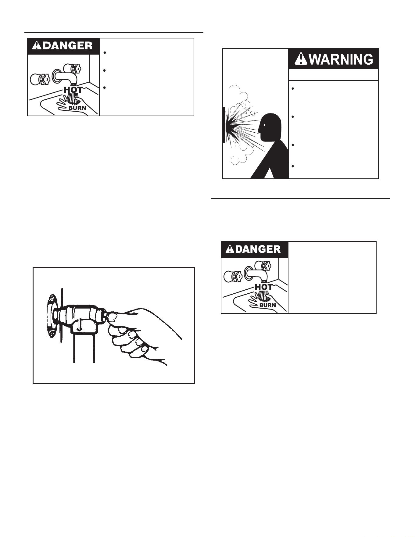
60
TEMPERATURE-PRESSURE RELIEF VALVE TEST
Burn hazard.
Hot water discharge.
Keep clear of Temperature-
Pressure Relief Valve
discharge outlet.
It is recommended that the Temperature-Pressure Relief Valve
should be checked to ensure that it is in operating condition every
6 months.
When checking the Temperature-Pressure Relief Valve operation,
make sure that (1) no one is in front of or around the outlet of the
Temperature-Pressure Relief Valve discharge line, and (2) that the
water discharge will not cause any property damage, as the water
may be extremely hot. Use care when operating valve as the valve
may be hot.
To check the temperature-pressure relief valve, lift the lever at the
end of the valve several times. See Figure 49 (page 60). The valve
should seat properly and operate freely.
If after manually operating the valve, it fails to completely reset and
continues to release water, immediately close the cold water inlet to
the water heater and drain the water heater. See Draining and Flushing
(page 60). Replace the Temperature-Pressure Relief Valve with
a properly rated/sized new one. See Temperature-Pressure Relief Valve
(page 21) for instructions on replacement.
DISCHARGE PIPE
TEMPERATURE-PRESSURE
RELIEF VALVE
Figure 49. Testing the Temperature-Pressure Relief Valve
If the Temperature-Pressure Relief Valve on the water heater weeps
or discharges periodically, this may be due to thermal expansion.
Note: Excessive water pressure is the most common cause of
Temperature-Pressure Relief Valve leakage. Excessive
water system pressure is most often caused by “thermal
expansion” in a “closed system.” See Closed Water Systems and
Thermal Expansion (page 20). The Temperature-Pressure
Relief Valve is not intended for the constant relief of thermal
expansion.
Temperature-Pressure Relief Valve leakage due to pressure build
up in a closed system that does not have a thermal expansion
tank installed is not covered under the limited warranty. Thermal
expansion tanks must be installed on all closed water systems.
DO NOT PLUG THE TEMPERATURE-PRESSURE RELIEF
VALVE OPENING. THIS CAN CAUSE PROPERTY DAMAGE,
SERIOUS INJURY OR DEATH.
Explosion Hazard
Temperature-Pressure Relief Valve
must comply with ANSI Z21.22-
CSA 4.4 and ASME code.
Properly sized temperature-
pressure relief valve must be
installed in opening provided.
Can result in overheating and
excessive tank pressure.
Can cause serious injury or death.
DRAINING AND FLUSHING
It is recommended that the water heater storage tank be drained and
ushed every 6 months to reduce sediment buildup. The water heater
should be drained if being shut down during freezing temperatures.
See Figure 2 and Figure 3 in Features and Components (page 11) for
the location of the water heater components described below.
• Burn hazard.
• Hot water discharge.
• Keep hands clear of drain
valve discharge.
TO DRAIN THE WATER HEATER STORAGE TANK:
1. Switch the Enable/Disable switch, located at the base of the water
heater, to the “Disable” position and then turn o the electrical
supply to the water heater.
2. Turn o the gas supply at the Main Gas Shuto Valve if the water
heater is going to be shut down for an extended period. See
Figure 39 (page 34).
3. Ensure the cold water inlet valve is open.
4. Open a nearby hot water faucet and let the water run until the
water is no longer hot.
5. Close the cold water inlet valve to the water heater.
6. Connect a hose to the water heater drain valve and terminate it
to an adequate drain.
7. Open the water heater drain valve and allow all the water to drain
from the storage tank.
8. Close the water heater drain valve when all water in the storage
tank has drained.
9. Close the hot water faucet opened in Step 4.
10. If the water heater is going to be shut down for an extended
period, the drain valve should be left open.
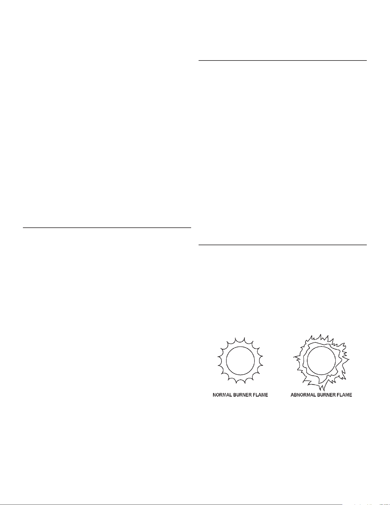
61
TO FLUSH THE WATER HEATER STORAGE TANK:
1. Switch the Enable/Disable switch, located at the base of the water
heater, to the “Disable” position and then turn o the electrical
supply to the water heater.
2. Ensure the cold water inlet valve is open.
3. Open a nearby hot water faucet and let the water run until the
water is no longer hot. Then close the hot water faucet.
4. Connect a hose to the drain valve and terminate it to an adequate
drain.
5. Ensure the drain hose is secured before and during the entire
ushing procedure. Flushing is performed with system water
pressure applied to the water heater.
6. Open the water heater drain valve to ush the storage tank.
7. Flush the water heater storage tank to remove sediment and
allow the water to ow until it runs clean.
8. Close the water heater drain valve when ushing is completed.
9. Remove the drain hose.
10. Fill the water heater - see Filling The Water Heater (page 49).
11. Turn on the electrical supply to place the water heater back in
operation and switch the Enable/Disable switch to the “Enable”
position.
12. Allow the water heater to complete several heating cycles to
ensure it is operating properly.
SEDIMENT AND LIME SCALE REMOVAL
Waterborne impurities consist of the particles of soil and sand which
settle out and form a layer of sediment on the bottom of the tank.
For convenience, sediment removal and lime scale removal should
be performed at the same time.
When water is heated dissolved minerals in the water such as
calcium and magnesium carbonate (lime scale) become less soluble.
As the water temperature rises these minerals will precipitate or “fall
out” of solution.
The amount of lime scale released from water is in direct proportion
to water temperature and usage. The higher the water temperature
or water usage, the more lime deposits are dropped out of the water.
Water hardness also aects lime scale accumulation. With the
temperature and usage being the same, hard water will release
more lime scale than softer water.
Lime scale reduces heating eciency as it accumulates inside a
water heater. Heating transfer surfaces become coated with lime
scale deposits which increases fuel costs to operate the water heater.
Lime scale deposits can also cause rumbling and pounding noises
as air molecules trapped in the lime scale escape when heated. Lime
scale accumulation also reduces the life span of water heaters. For
these reasons a regular schedule for deliming should be set up.
The depth of lime accumulation in the bottom of the water heater
should be measured periodically. Inspect by removing the cleanout
cover once every 6 months at rst. Deliming maintenance should
then be performed based on the time it takes for 1 inch (2.5 cm) of
lime to accumulate in the bottom of the water heater.
CHEMICAL LIME SCALE REMOVAL
To dissolve and remove more stubborn lime scale deposits, UN-
LIME
®
Professional Delimer should be used.
UN-LIME
®
Professional Delimer is an easy to handle patented food
grade acid formulated specically for lime scale removal from all
types of water using equipment. Hydrochloric base acids must not
be used to delime the water heaters covered in this manual.
Follow the instructions on the UN-LIME
®
to delime the water heater.
Note: Contact Technical Support for assistance in ordering the UN-
LIME
®
Professional Delimer.
BURNER OPERATION AND INSPECTION
Flood damage to a water heater may not be readily visible or
immediately detectable. However, over a period of time a ooded
water heater will create dangerous conditions which can cause
DEATH, SERIOUS BODILY INJURY, OR PROPERTY DAMAGE.
Contact a qualied installer or service agency to replace a ooded
water heater. Do not attempt to repair the unit! It must be replaced!
At least once a year a visual inspection should be made of the
main burner and the hot surface igniter assembly for proper ame
characteristics and ignition sequences. This can be done by removing
the Outer Door and viewing the main burner operation through the
Viewport on the Inner Door. See Figure 2 (page 11) and Figure
3 (page 12) for the location. The main burner should provide
complete combustion of gas, ignite rapidly, give reasonably quiet
operation, and cause no excessive ame lifting from the burner ports.
If the proper ame characteristics are not evident, make sure that
the ow of combustion and ventilation air is not blocked.
You should also check for sooting. Soot is not normal and will impair
proper combustion. A visual inspection of the main burner and HSI
igniter assembly should also be done at least once a year.
Soot build-up indicates a problem that requires correction before
further use. Turn “OFF” gas to water heater and leave o until repairs
are made, because failure to correct the cause of the sooting can
result in a re causing death, serious injury, or property damage.
BURNER FLAME INSPECTION
Check main burner every three months for proper flame
characteristics. You can see the burner ame through the access
door. See Figure 2 (page 12) and Figure 3 (page 13) for the
location of the access door.
The main burner should display the following characteristics:
• Provide complete combustion of gas.
• Cause rapid ignition and carry over of ame across entire burner.
• Give reasonably quiet operation during initial ignition, operation
and extinction.
• Cause no excessive lifting of ame from burner ports. See Figure
50.
Figure 50. Normal and Abnormal Burner Flames
If the preceding burner characteristics are not evident, check for
accumulation of lint or other foreign material that restricts or blocks
the air intake tting or air intake terminal. See Figure 2 (page 11)
and Figure 3 (page 12) for the location of the air intake tting.
To ensure continued good performance, keep the area around the
water heater clean and free from lint and debris. Sweep the oor
around the water heater regularly. This will reduce the dust and dirt
which can enter the burner and heat exchanger, causing improper
combustion and sooting.
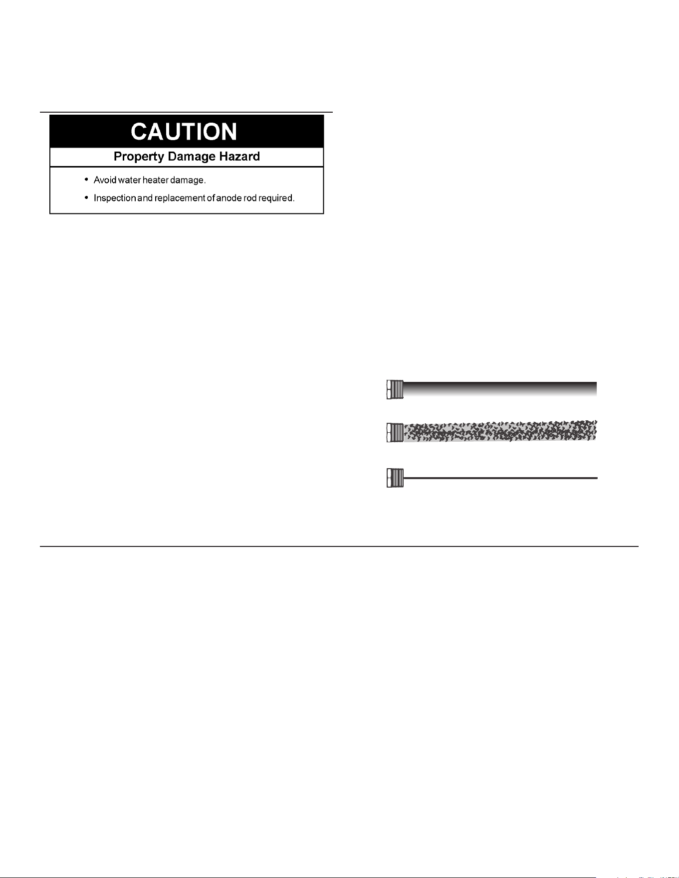
62
If the air intake tting and air intake terminal are clear and the burner
continues to exhibit abnormal ames, contact a qualied service
agency or have a qualied service professional inspect and clean
the burner.
ANODE ROD INSPECTION
Each water heater contains at least one anode rod, which will slowly
deplete (due to electrolysis) prolonging the life of the water heater
by protecting the glass-lined tank from corrosion. Adverse water
quality, hotter water temperatures, high hot water usage, hydronic
heating devices, and water softening methods can increase the rate
of anode rod depletion. Once the anode rod is depleted, the tank
will start to corrode, eventually developing a leak.
Certain water conditions will cause a reaction between the anode
rod and the water. The most common complaint associated with
the anode rod is a “rotten egg smell” produced from the presence
of hydrogen sulde gas dissolved in the water.
Important: Do not remove this rod permanently as it will void any
warranties. A special anode rod may be available if water
odor or discoloration occurs.
Note: This rod may reduce but not eliminate water odor problems.
The water supply system may require special filtration
equipment from a water conditioning company to successfully
eliminate all water odor problems.
Articially softened water is exceedingly corrosive because the
process substitutes sodium ions for magnesium and calcium ions.
The use of a water softener may decrease the life of the water
heater tank.
The anode rod should be inspected annually until the condition of
the anode rod dictates its replacement.
The following are typical (but not all) signs of a depleted anode rod:
• The majority of the rods diameter is less than 3/8”.
• Signicant sections of the support wire (approx. 1/3 or more of
the anode rod’s length) are visible.
If the anode rod show signs of either or both it should be replaced.
Note: Whether re-installing or replacing the anode rod, check for
any leaks and immediately correct if found.
To replace the anode, do the following:
1. Turn o gas supply to the water heater.
2. Shut o the water supply and open a nearby hot water faucet to
depressurize the water tank.
3. Drain approximately 5 gallons of water from tank. See Draining and
Flushing (page 60) for proper procedures. Close drain valve.
4. Remove old anode rod.
5. Use Teon
®
tape or approved pipe sealant on threads and install
new anode rod.
6. Turn on water supply and open nearby hot water faucet to purge
air from water system. Check for any leaks and immediately
correct any if found.
7. Restart the water heater as directed.
New Unused Anode Rod
Partially-Consumed Anode Rod
Fully-Depleded Anode Rod
Figure 51. Anode Rod Depletion
SERVICE
If a condition persists or you are uncertain about the operation of the
water heater contact a qualied service technician.
Use this guide to check a leaking water heater. Many suspected
leaks are not leaking tanks. Often the source of the water can be
found and corrected.
If you are not thoroughly familiar with gas codes, your water heater,
and safety practices, contact your gas supplier or qualied installer
to check the water heater.
Read this manual rst. Then before checking the water heater make
sure the gas supply has been turned “OFF”, and never turn the gas
“ON” before the tank is completely full of water.
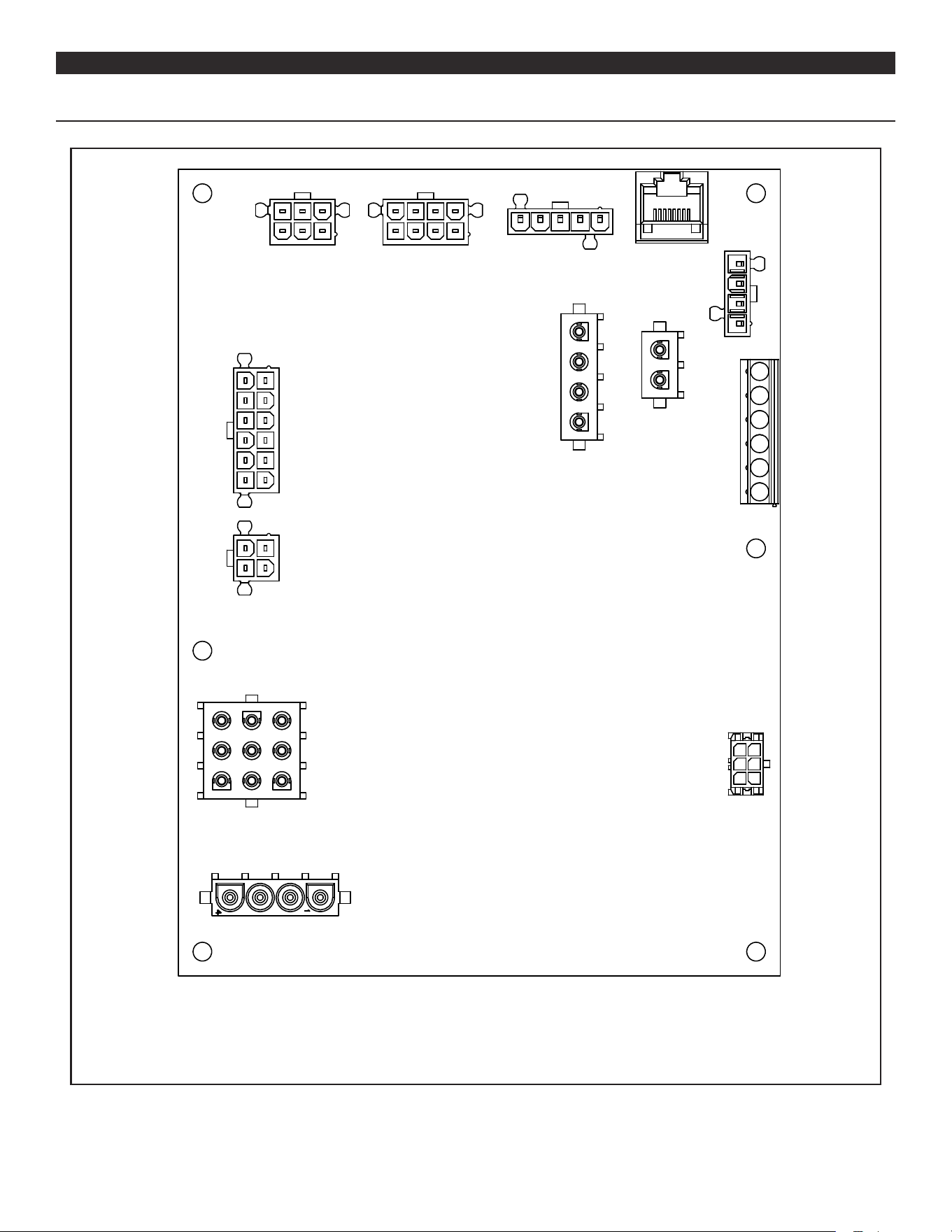
63
DIAGRAMSDIAGRAMS
CCB - CENTRAL CONTROL BOARD LAYOUT
11
12
1
J16
J5
J3
J13
J4
J17
J10
J9
J14
J15
J1
J6
J12
1
1
1
1
1
1
1
1
1
1
1
1
2
2
2
2
2
2
2
2
2
2
2
2
3
3
3
3
3
3
3
3
3
3
3
4
4
4
4
4
4
4
4
4
4
4
5
5
5
5
5
5
6
6
6
6
6
6
7
78
8
8
9
9
7
10
8
Figure 52. Central Control Board Layout
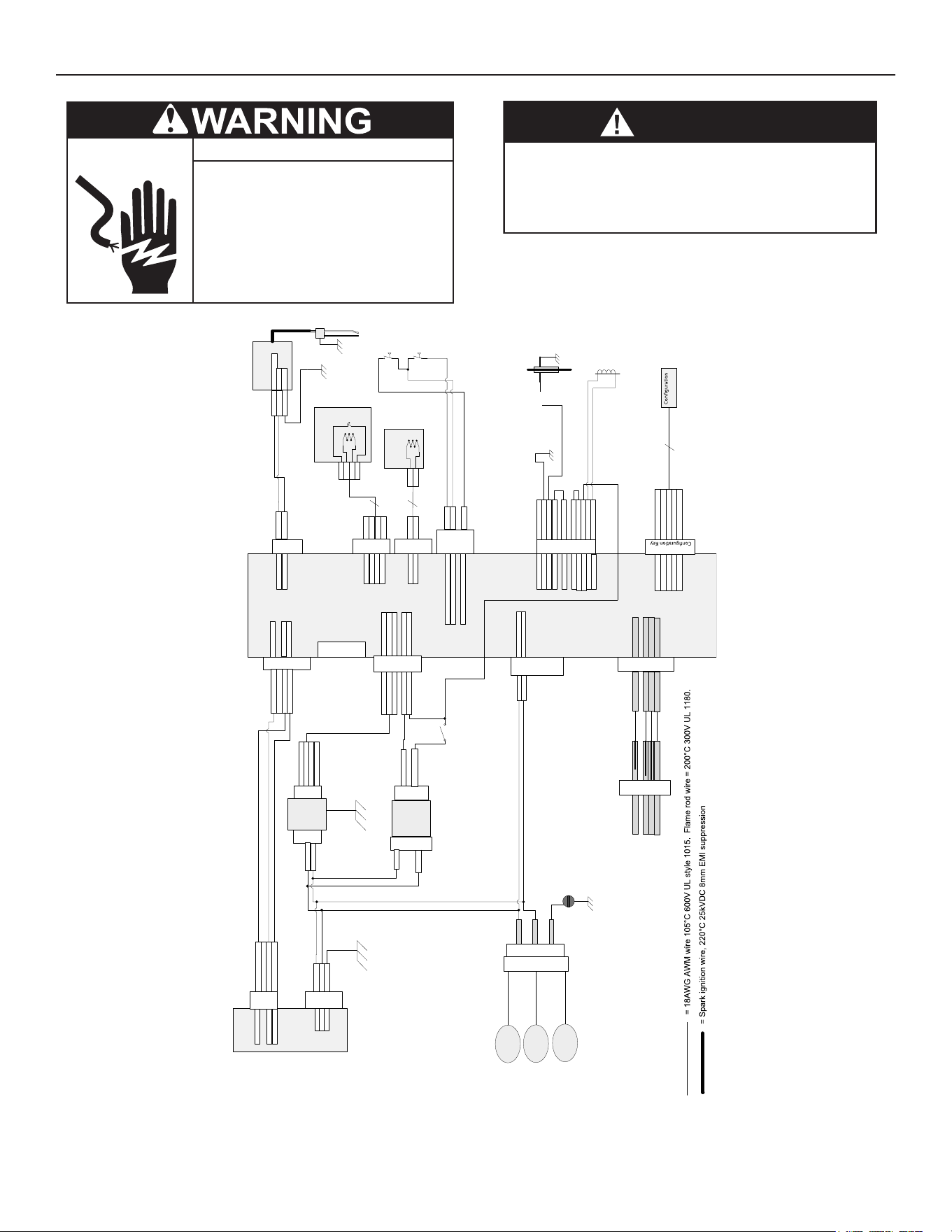
64
WIRING DIAGRAM
● Disconnect from electrical supply before
servicing unit. Replace all doors and
panels before operating heater.
Electrical Shock Hazard
● If any of the original wires supplied with
the appliance must be replaced, it must
be replaced with appliance wire material
with minimum temperature rateing of
105°C and a minimum size of No. 18 AWG.
CAUTION
Label all wires prior to disconnection when servicing controls.
Wiring errors can cause improper and dangerous operation. Verify
proper operation after servicing
.
5
4
Blower
L1
Neutral
PE
PWM Signal
Speed f-back
Dgnd
Blower
Speed
2 White / Orange
4 White / Blue
5 White / Green
1 Black
2 White
3 Green
Blower Power
Power
Supply J1
2 White
3 Black
Power
Supply J2
Power
Supply
1 Blue
3 Orange
4 White/Green
2 White/Blue
4 White/Orange
5 White/Green
CCB J5
Blower Logic
PWM Signal
Speed f-back
Dgnd
No factory
connections
CCB J17
Low Voltage Field
Central Control Board
(CCB)
Neutral
Line to Spark
CCB J6
Power Out
1 Blue
2 Brown
1 Brown
2 White/Blue
4 Blue
5 Orange
6 White/Green
CCB J16
Low Voltage In
24VAC
24VAC
12VDC
5VDC
Dgnd
1 Red
2 Black
CCB J9
Upper Probe
ECO
Thermistor
4 Red
3 Black
ECO
Thermistor
1 Black
2 Black
CCB J10
Lower Probe
Thermistor
Thermistor
2
Inlet return
Outlet return / Inlet power
Outlet power
1 White
2 Red
CCB J15
Pressure
Switches
4 Green
Neutral
L1
9 White
CCB J1
HIGH Voltage In
8 Black
1 Blue
3 Yellow
4 Orange
5 Violet
CCB J3
+5V
Data +
Data -
D gnd
SDA (data)
SCL (data)
Write protect
+5V
Dgnd
CCB J12
2 Red
3 Green
4 White/Brown
5 White/Blue
6 White/Orange
Key
Gas Valve
L1
Neutral
Protective
Earth
MAIN INPUT
3 CIRCUIT BARRIER
TERMINAL BLOCK
Metal Oxide Varistors
White
Black
Green
GROUND SCREW
CCB J14
Limit String
1 Blue
2 Green
3 Yellow
4 Black
6 Black
8 Black
9 Red
10 Brown
11 Violet
12 Gray
Anode
Dgnd
Flame Rod
Condensate
Gas V Switch
Gas V 24V
24V Rtn
Condensate
Gas PS
Gas V Switch
Yellow
Flame
Rod
Spark
Module
Switched L1
Neutral
1 Brown
2 Blue
3 Green
Ground
Red
Black
Red
Black
Upper Temperature
Probe / ECO
Spark
Rod
Black
Black
Lower
Temperature
Probe
Outlet
Pressure
Switch
Inlet Pressure
Switch
Enable/Disable
Transformer
Secondary
White / Red
White / Blue
Transformer
Primary
Black
White
Transformer
1 Blue
3 Yellow
4 Orange
Display J1
5 Violet
+5V
Data +
Data -
D gnd
Figure 53. Wiring Schematic (All Models)
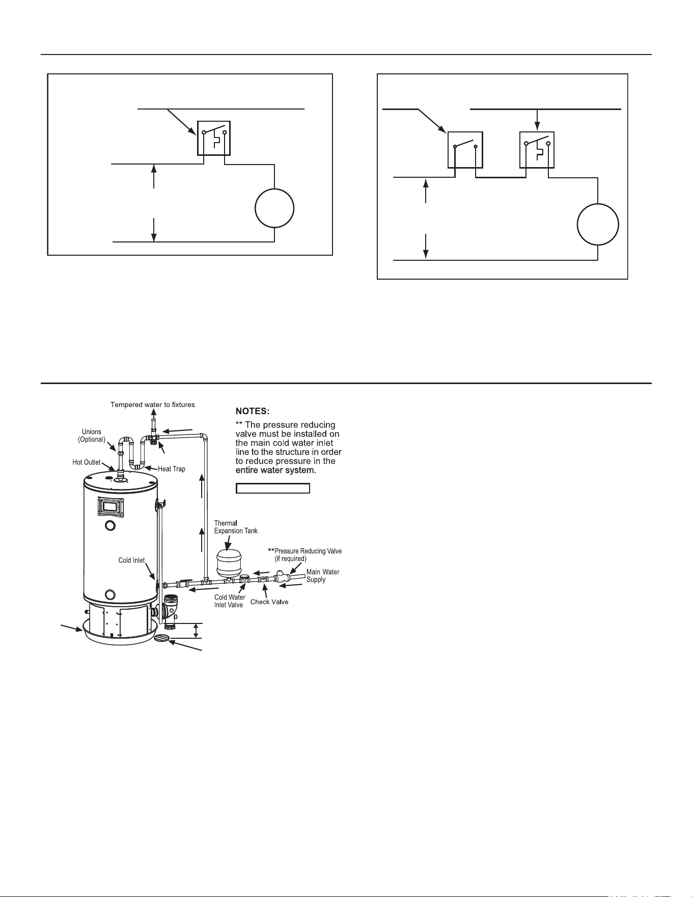
65
CIRCULATION PUMP WIRING DIAGRAMS
FIELD SUPPLIED TEMPERATURE CONTROL
INSTALLED IN THE STORAGE TANK
OR CIRCULATING LOOP RETURN LINE
CIRC
PUMP
MOTOR
L1 HOT
L2 NEUTRAL
120 VAC
POWER
Figure 54. Circulating Pump Wiring Diagram - Storage Tank or
Building Recirculation
Note: Use separate 120 vac power supply for pump circuit. Do not
share power with appliance as this may cause electrical line
noise and lead to erratic control system operation.
FIELD SUPPLIED TEMPERATURE
CONTROL INSTALLED IN THE
CIRCULATING LOOP RETURN LINE
DISHWASHER
TOGGLE
SWITCH
CIRC
PUMP
MOTOR
L1 HOT
L2 NEUTRAL
120 VAC
POWER
Figure 55. Circulating Pump Wiring Diagram Dishwasher Loop with
Toggle Switch
Note: Use separate 120 vac power supply for pump circuit. Do not
share power with appliance as this may cause electrical line
noise and lead to erratic control system operation.
PIPING DIAGRAMS
Check local codes.
Mixing Valve
Metal
Drain
Pan
6" (15.2cm)
Air Gap Max.
Adequate Drain
Figure 56. Typical One-Temperature System Piping Installation (All
Models)
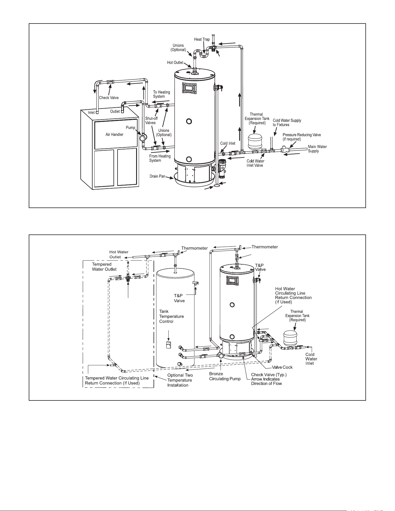
66
Drain
6" Max.
Above Drain
Mixing Valve
Figure 57. Air Handler Piping Installation (All Models)
Manual Shut Off Valve (Typ)
Mixing
Valve
(180°F Max.)
Figure 58. Water Heater With Auxiliary Storage Tank,
One or Two Temperature System (With or Without Building Recirculation)

67
NOTESNOTES

68
300 Maddox Simpson Parkway
Lebanon, TN 37090
Phone: 1-800-722-2101 • Fax: 615-547-1000
Technical Service email: 2tech@lochinvar.com
www.Lochinvar.com
Copyright © 2020 Lochinvar, LLC. All rights reserved.