
Varex Imaging
1678 South Pioneer Road
Salt Lake City, UT 84104-4298
USA
tel 801 973 5000 650 493 4000
fax 801 973 5050
Proprietary and Confidential Information
Radio Module Manual
A. General Description
The WNFQ268AXI(BT) is a Qualcomm Atheros WCN6856-based Wi-Fi 6E (IEEE 802.11ax)
radio module in an M.2 2230 E-key form factor. The module interfaces via PCI Express
(PCIe) and is integrated into Varex Imaging wireless X-ray detector systems
The FCC and IC identiers for the WNFQ268AXI(BT) radio module integrated into Varex
Imaging products are listed below:
▪ FCC ID: ZZ6-WNFQ268AXIBT
▪ IC: 9909A-WNFQ268AXIB
This transmitter module is approved exclusively for use within Varex Imaging Corporation
products and is not authorized for standalone sale or third-party integration.
B. Key Feature
▪ Compliant with IEEE 802.11 ax/ac/n
▪ Supports 2x2 Multi-User Multiple-Input Multiple Output (MU-MIMO)
▪ 5 GHz/6 GHz support
▪ 20 MHz/40 MHz/80 MHz/160 MHz channel bandwidth for 5 GHz/6 GHz
▪ Supports STA mode and Soft AP Mode
▪ Antenna Connector: 2 x IPEX MHF4
▪ Data rate:
o 802.11n: MCS0~15
o 802.11ac: MCS0~9
o 802.11ax: HE0~11
▪ Frequency:
o 5.150GHz~5.850GHz
o 5.925~7.125GHz
▪ Modulation:
o 802.11n: OFDM (BPSK, QPSK, 16-QAM, 64-QAM)
o 802.11ac: OFDM (BPSK, QPSK, 16-QAM, 64-QAM, 256-QAM)
o 802.11ax: OFDMA (BPSK, QPSK, 16-QAM, 64-QAM, 256-QAM, 1024-QAM
▪ Security: WPA2, WPA3
Varex Imaging
1678 South Pioneer Road
Salt Lake City, UT 84104-4298
USA
tel 801 973 5000 650 493 4000
fax 801 973 5050
Proprietary and Confidential Information
▪ Operating Voltage DC 3.3V
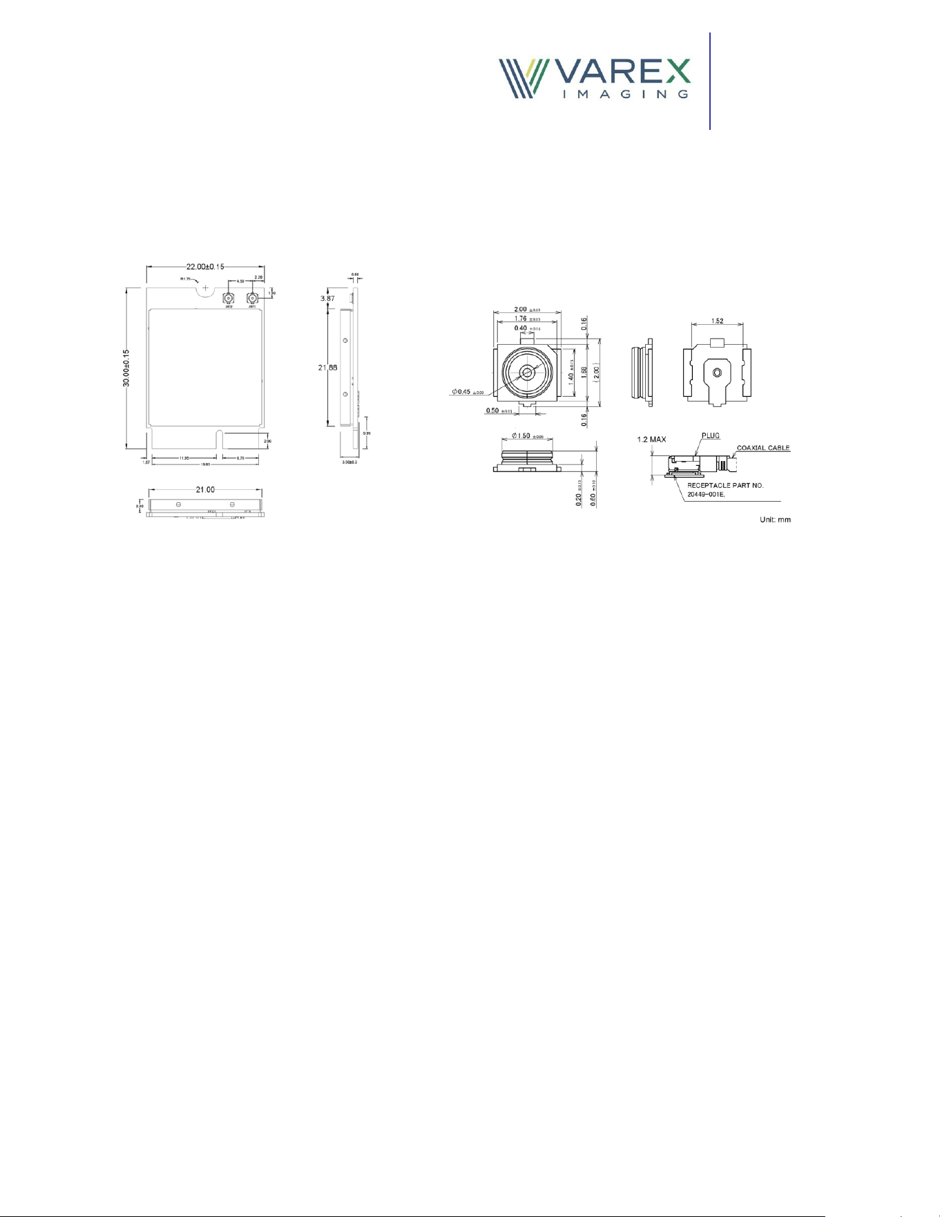
C. Mechanical Dimension (mm)
D. Installation
▪ Connect the Radio module to the PCIe slot of the host
▪ Install Wi-Fi driver
▪ Connect the antennas to the MHF4 ports of the radio module using coaxial cables
▪ Connect to the Wireless Network
E. FCC and ISED Applicable Rules
This radio module has been tetsed and found complient with the following standards:
▪ FCC 47 CFR PART 15 SUBPART E
▪ ISED RSS-247 ISSUE 4
▪ ISED RSS-248 ISSUE 3
▪ ISED RSS-GEN ISSUE 5+A1+A2
The FCC and ISED applicable rules must be included in the host manual for any host
device that incorporates this radio module.
Varex Imaging
1678 South Pioneer Road
Salt Lake City, UT 84104-4298
USA
tel 801 973 5000 650 493 4000
fax 801 973 5050
Proprietary and Confidential Information
F. Operational Use Condition
This radio module has been tested and found to comply with emissions limits for a Class B,
part 15 of the FCC Rules. These limits are designed to provide reasonable protection
against harmful interference. This equipment generates, uses and can radiate radio
frequency energy and, if not installed and used in accordance with the instructions, may
cause harmful interference to radio communications. If this equipment does cause
harmful interference to radio or television reception, which can be determined by turning
the equipment o and on, the user is encourage to try to correct the interference by one or
more of the following measures:
▪ Reorient or relocate the receiving antenna
▪ Increase the separation between the equipment and receiver
G. RF Exposure Statements
This transmitter must not be co-located with, or operated in conjunction with, any other
antenna or transmitter.
This equipment complies with the FCC RF exposure limits set forth for an uncontrolled
environment. This radio module should be installed and operated with a minimum distance
of 20cm between the radiator and your body or nearby persons.
This radio module has been approved by Federal Communications Commission to operate
with the antenna listed below.
The RF exposure statements must be included in the host manual for any host device that
incorporates this radio module.
H. Host Product Compliance Verication Requirements
When this radio module is integrated into a host device, the nal host product must be
evaluated to conrm continued compliance with FCC requirements. The host
manufacturer is responsible for performing verication testing with all transmitter(s) in the
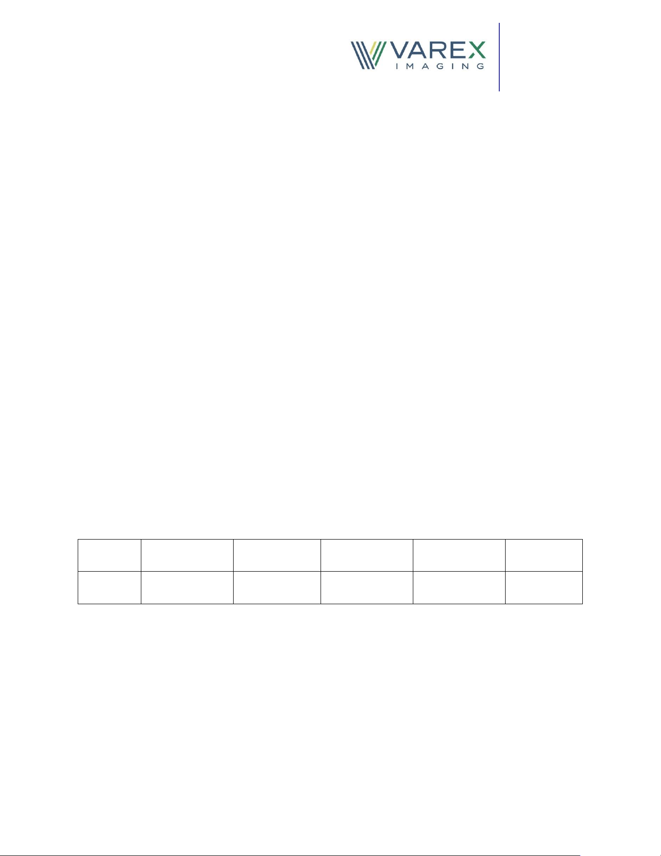
Antenna
Type
Brand
Antenna
Part Number
Maximum
Gain at 5GHz
Maximum
Gain at 6 GHz
Antenna
Connector
CBSA-
PCB
Varex Imaging
Corporation
171434
5.84 dBi
7.87 dBi
MHF4L
Varex Imaging
1678 South Pioneer Road
Salt Lake City, UT 84104-4298
USA
tel 801 973 5000 650 493 4000
fax 801 973 5050
Proprietary and Confidential Information
host operating simultaneously. This may be accomplished by spot-checking emissions
from the fully assembled host device while it is congured in typical operational modes.
Testing should conrm that both fundamental-frequency emissions and spurious
emissions comply with all applicable FCC rules when the host operates as a composite
system.
I. Host Labeling Requirement
If the FCC identication number is not visible when the module is installed inside another
device, then the outside of the device into which the module is installed must also display
a label referring to the enclosed module. The exterior label can use wording such as the
following:
“Contains FCC ID: ZZ6-WNFQ268AXIBT”
“Contains IC: 9909-WNFQ268AXIB”.
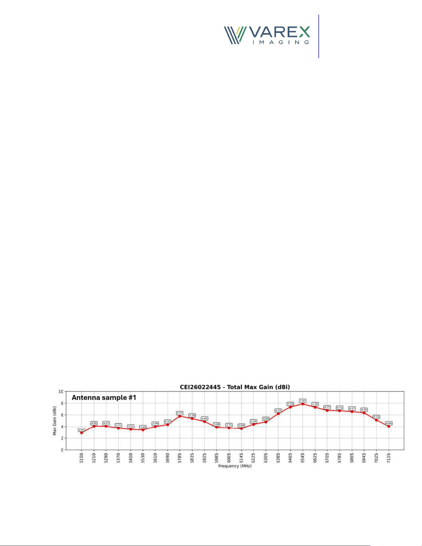
J. Antenna Specications
▪ The radio module uses two identical antennas for MIMO 2X2 operation
▪ The antenna type is CBSA (cavity back slot antenna) – PCB which is designed to be
embedded inside Varex Imaging wireless detectors
▪ Varex part number of the antenna is 171434
▪ The antenna supports 5GHz and 6GHz bands for WiFi 6E operation
▪ Antenna is connected to WiFi 6E radio module with coaxial cable
▪ Antenna connector is MHF4L
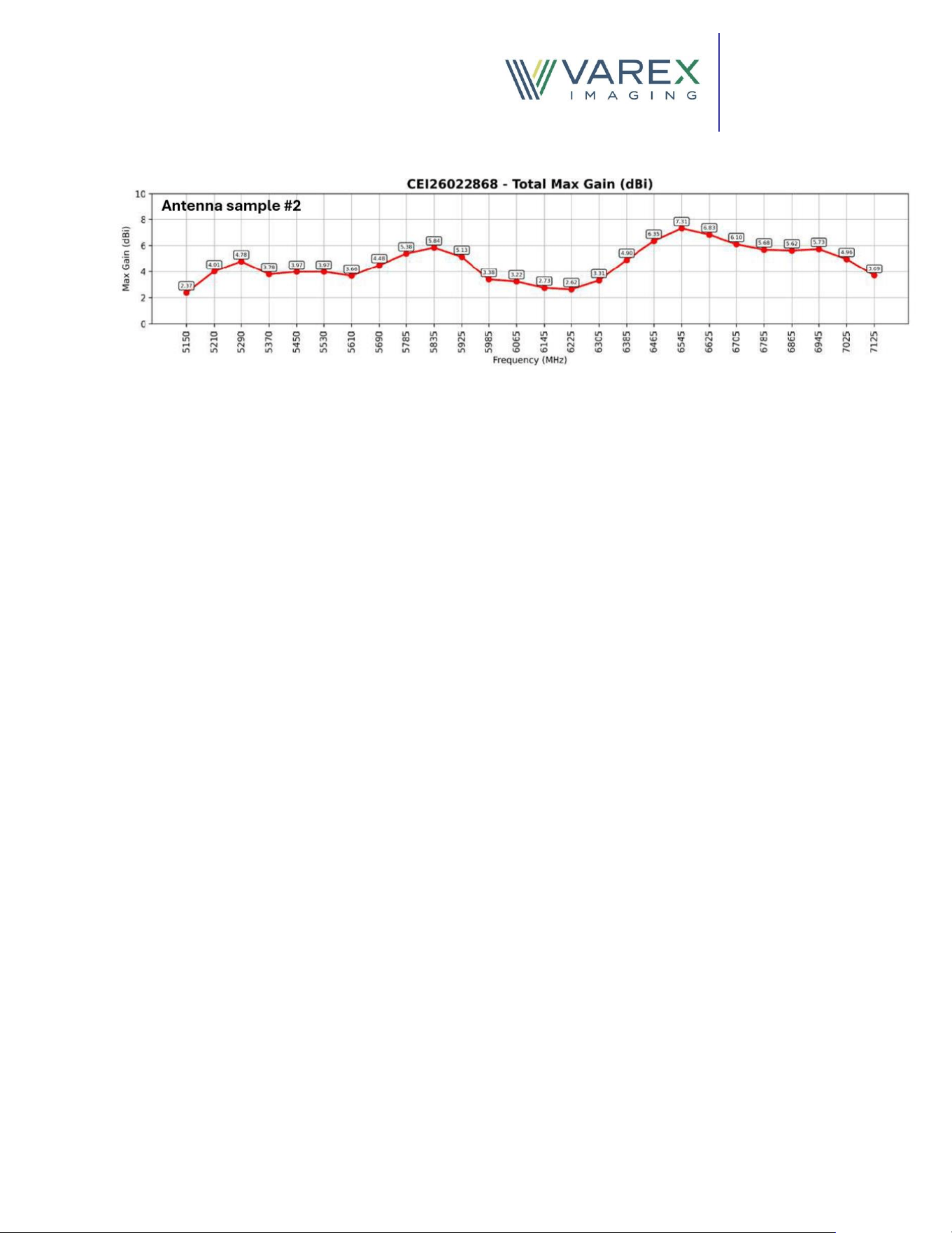
▪ Antenna gain measurements were performed on two antenna samples, and the
total maximum gain values are provided below.
Varex Imaging
1678 South Pioneer Road
Salt Lake City, UT 84104-4298
USA
tel 801 973 5000 650 493 4000
fax 801 973 5050
Proprietary and Confidential Information
K. Additional Notes
▪ The radio module supports Bluetooth, BLE, 2.4 GHz Wi-Fi, and 802.11a
functionality; however, these features are not enabled when the module is
integrated into Varex Imaging products. The host software disables these
capabilities in the nal product conguration
▪ AP mode is enabled in the radio module at 5GHz and 6 GHz bands
▪ AP mode operation in DFS band is disabled in the host software
▪ Software security declaration check list is addressed in “UNII Software Security”
document
▪ The bandwidth reduction technique is used for the purpose of incumbent
avoidance.
▪ Channel puncturing is not used for the purpose of incumbent avoidance.
▪ The new antenna is being certied with this radio module
Varex Imaging
1678 South Pioneer Road
Salt Lake City, UT 84104-4298
USA
tel 801 973 5000 650 493 4000
fax 801 973 5050
Proprietary and Confidential Information
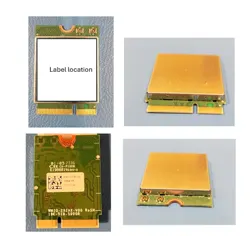
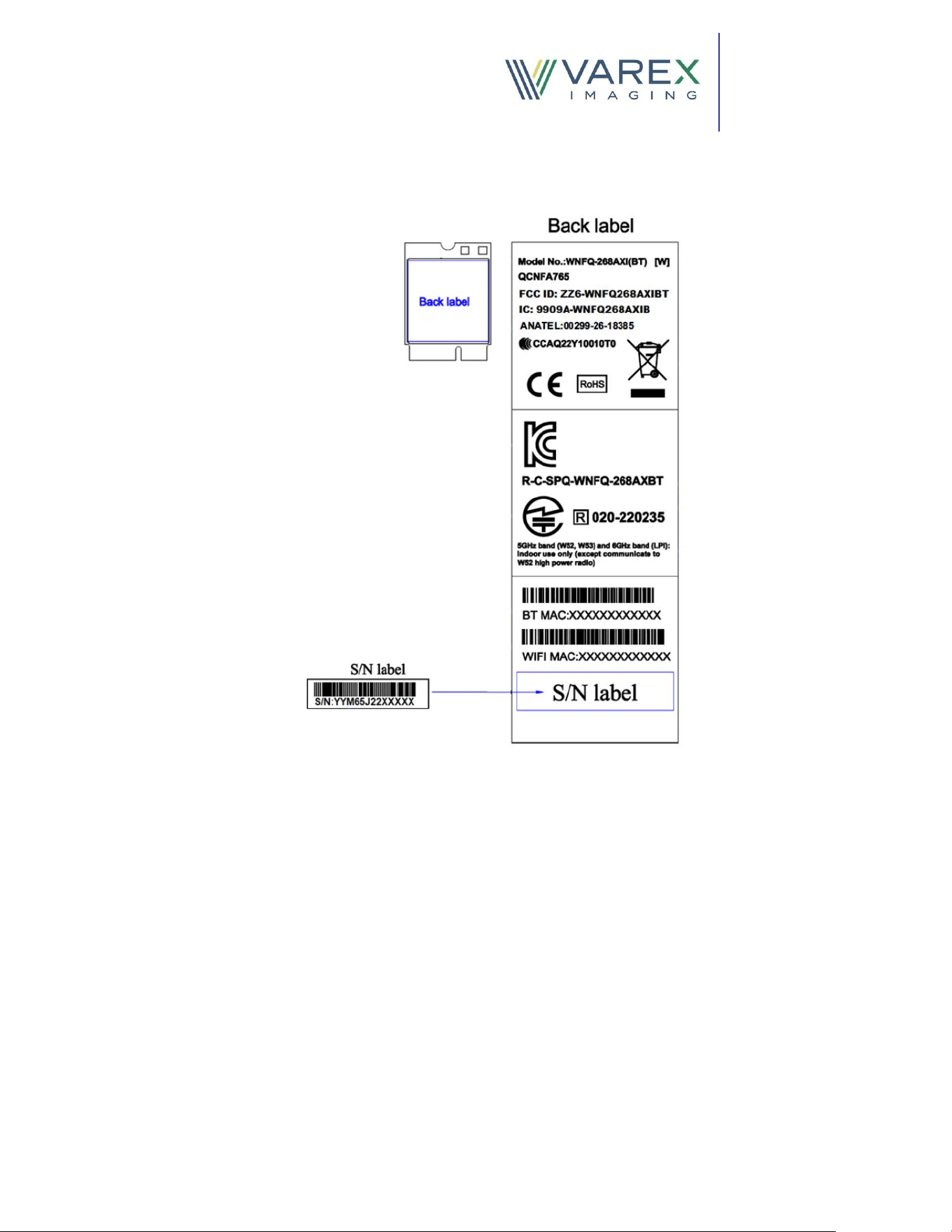
L. Radio Module Label