GMKtec NUCBOX K12 USER MANUAL

Copyright Notice
©Shenzhen GMK Technology Co., Ltd.All rights reserved.
This user manual, including but not limited to all information contained within it, is protected by copyright law.
Without the permission of ShenZhen GMK Technology Co., Ltd. (hereinafter referred to as "GMK"),
reproduction, copying, extraction, translation, or any other unauthorized use is strictly
prohibited.
Friendly Reminder & Disclaimer
Thank you for choosing GMKtec. Please read this user manual carefully before use and keep it for later
reference.
The information in this document is subject to change without notice, and no content herein shall be
construed as constituting any additional warranty. GMKtec reserves the right to update product
specifications, drivers, and this manual at any time. For the latest version, please visit our customer service
website: www.gmktec.com.
Please note that a wireless dongle (usually included with your keyboard and mouse set) is required for initial
Microsoft account setup if you use a wireless keyboard or mouse. After setup is completed, you may connect
other wireless devices via Bluetooth and Wi-Fi.
If you encounter any issues during use, please contact us through the email address provided in this manual.
We will provide support as soon as possible.
This manual is provided “as is” and “as available.” To the fullest extent permitted by applicable law, GMKtec
disclaims all express or implied warranties, including but not limited to implied warranties of merchantability,
fitness for a particular purpose, and non-infringement of third-party rights. GMKtec shall not be liable for any
technical or editorial errors or omissions contained in this document.
You assume all risks associated with the use of this manual. GMKtec, its licensors, and their respective officers,

directors, employees, agents, and affiliates shall not be liable for any direct, indirect, incidental, consequential,
special, punitive, or other damages (including but not limited to loss of profits, business interruption, or data
loss) arising from or related to this manual or the use of the product, even if advised of the possibility of such
damages.
Some jurisdictions may not allow the full exclusion or limitation of implied warranties or liability for certain
damages. In such cases, the above limitations or exclusions may not fully apply to you.
All third-party product names or content mentioned in this manual are the property of their respective
owners and are protected by intellectual property laws and international treaties.
GMKtec’s warranty and service shall be invalidated under the following conditions:
(1) The product has been repaired, modified, disassembled, or had components replaced without GMKtec’s
authorization.
(2) The product serial number is defaced, altered, or removed.

Contents
About This User Manual.......................................................................................................................................................................1
Prompt Description.......................................................................................................................................................................1
Package Box Contents.................................................................................................................................................................2
Getting to Know Your Mini PC ...........................................................................................................................................................3
About the Device ........................................................................................................................................................................... 3
Front View............................................................................................................................................................................... 3
Back View ................................................................................................................................................................................ 5
Technical specifications...............................................................................................................................................................8
Using Your Mini PC................................................................................................................................................................................ 9
Connection Steps ...........................................................................................................................................................................9
Attached VESA Installation ........................................................................................................................................................ 9
Basic Setting ................................................................................................................................................................................. 10
Entering the BIOS Settings ............................................................................................................................................. 10
Instructions to Change Boot Mode to Auto Power On (Power On).................................................................11
Instructions to Configure Wake-On-LAN ..................................................................................................................14
Instructions to Configure Thermal Power Mode.....................................................................................................17
Instructions to Configure Fan Speed.......................................................................................................................... 20
Upgrading Your Mini PC....................................................................................................................................................................25
Disassembly Method..................................................................................................................................................................25
Installing Memory Modules ......................................................................................................................................................27
Installing M.2 SSDs......................................................................................................................................................................27
Installing a Wireless Network Card.......................................................................................................................................28
Certification & Compliance...............................................................................................................................................................29

FCC Compliance Statement .....................................................................................................................................................29
EU Declaration Of Conformity ................................................................................................................................................29
Appendix.................................................................................................................................................................................................32
Safety Warnings and Precautions.........................................................................................................................................32
Use Environment .........................................................................................................................................................................32
Operation & Maintenance........................................................................................................................................................32
Usage Precautions......................................................................................................................................................................33
Service and Support............................................................................................................................................................................34

1
About This User Manual
This user manual provides an overview of the hardware settings and software features of the Mini PC. It is
organized into the following chapters:
Chapter 1: Getting to Know Your Mini PC
This chapter introduces the hardware components of the Mini PC.
Chapter 2: Using Your Mini PC
This chapter covers the basic operations of the Mini PC.
Chapter 3: Upgrading Your Mini PC
This chapter provides information on how to upgrade the Mini PC.
Chapter 4: Certification & Compliance
This chapter includes product certification statements and compliance information for different regions.
Chapter 5: Appendix
This chapter contains safety warnings, precautions, and proper use guidelines.
Chapter 6: Service and Support
This chapter provides official contact information and after-sales support channels.
Prompt Description
The instructions for use of specific icons and information in the manual are as follows:
Important! This information contains important information that must be followed to complete the task.
Note: This information contains additional tips and helpful information to assist in completing the task.
Warning! This information contains vital information that must be followed to ensure user safety and avoid
damage to the Mini PC's data or components.
2
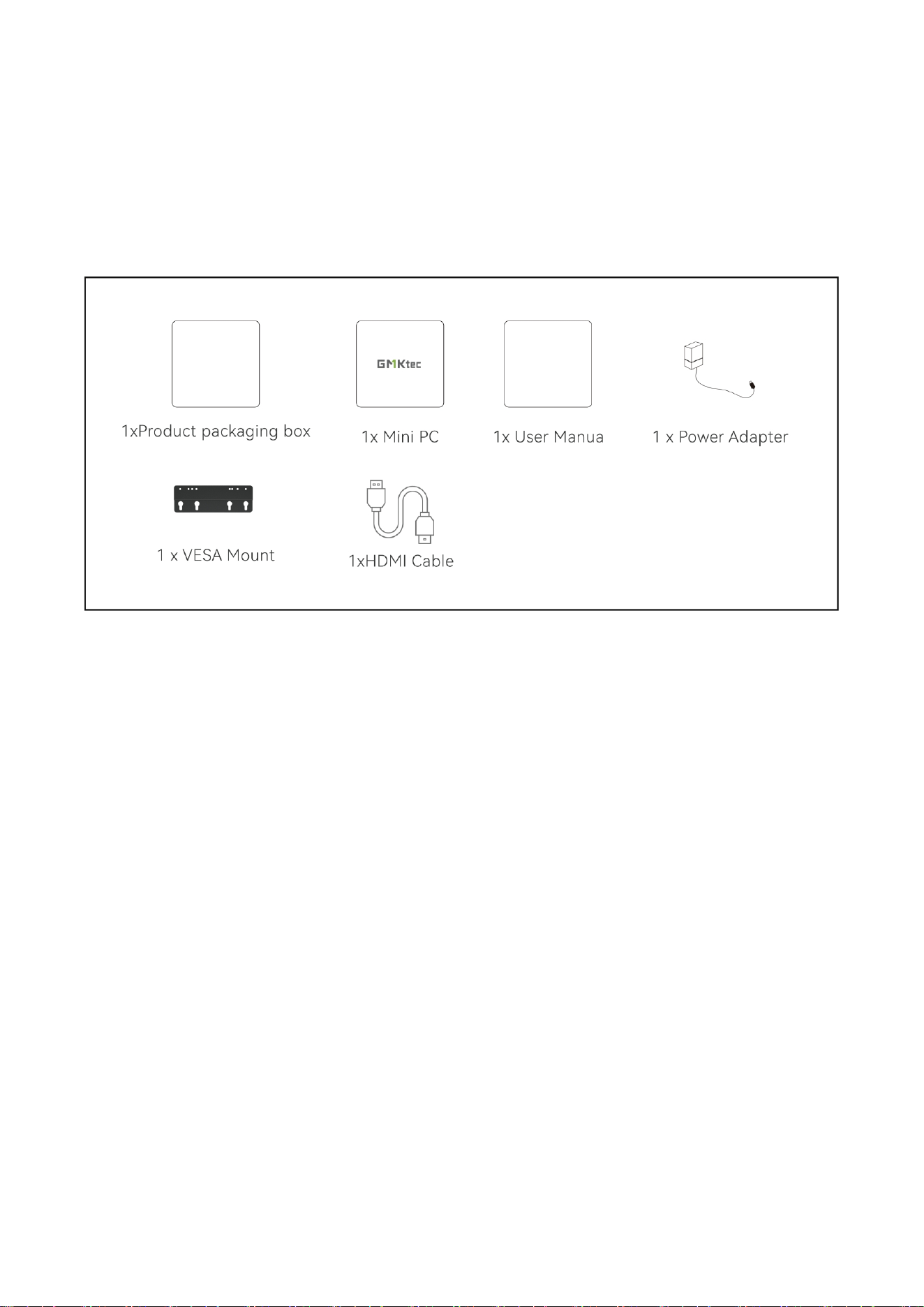
Package Box Contents
Your Mini PC package box should include the following items:
1xProduct packaging box+1x Mini PC +1x User Manual/Warranty Card +1 x Power Adapter + 1 x VESA Mount
+1xHDMI Cable
Notes:
Images are for reference only. The actual product may vary by region.Please refer to the product you
purchased.
*The included power adapter may vary depending on the model and region
Accessories included with your Mini PC may differ based on the model. For detailed accessory information,
please refer to the user manual of the specific model.
During the warranty period, if the product or its accessories experience any fault under normal usage
conditions, please contact a GMK authorized service center with your warranty card and the faulty product.
3
Getting to Know Your Mini PC
About the Device
Before use, please familiarize yourself with the interface and buttons of the device.
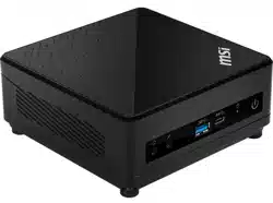
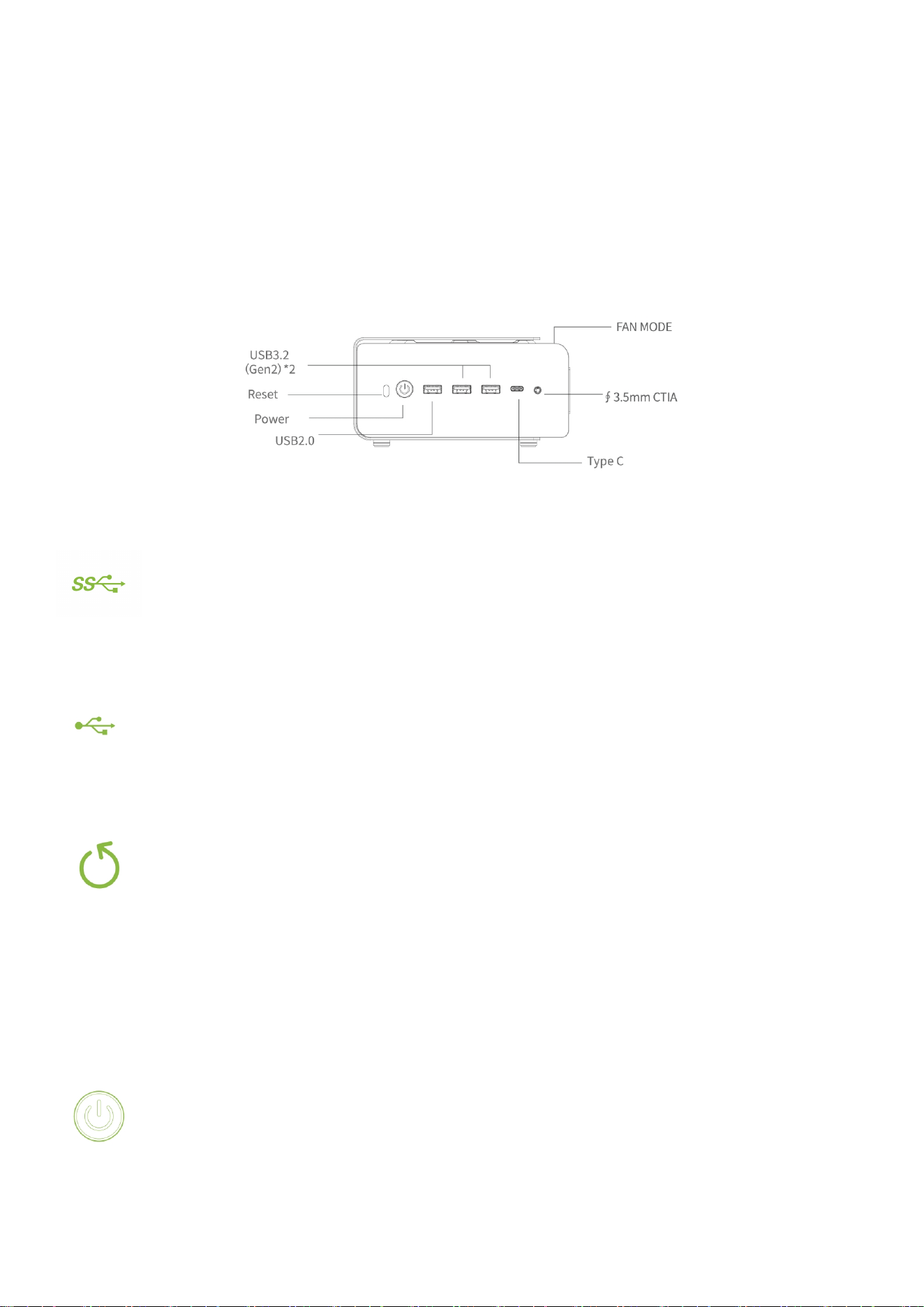
Front View
USB 3.2 (Gen2):
The USB3.2 port provides a transfer speed of up to 10Gbps.
USB2.0
This USB 2.0 port provides a transfer speed of up to 480 Mbps.
Reset
When the computer is running normally, pressing this key will directly restart the system. When
the computer is powered off, pressing this key will clear the CMOS settings and restore the BIOS
to its factory default values.
Power Button
The power button is used to turn the Mini PC on or off.
It features an integrated white LED indicator: the LED stays solid when the device is on.

4
FAN-MODE(Lighting Effect Control):
Adjustable system fan lighting effects. A short press switches between 13 lighting modes; a long
press turns the lights off, and a short press turns them on.
Note: BIOS does not support lighting effect settings.
∮3.5mm CTIA Audio :
The port is used to connect audio output devices such as speakers or headphones. It can also be
used to connect external microphones or other audio output devices
TYPE-C
The Type-C port supports the USB 3.2 Gen 2 specification, as well as PD power delivery, DP
video output, data transfer, and charging functions.
5
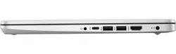
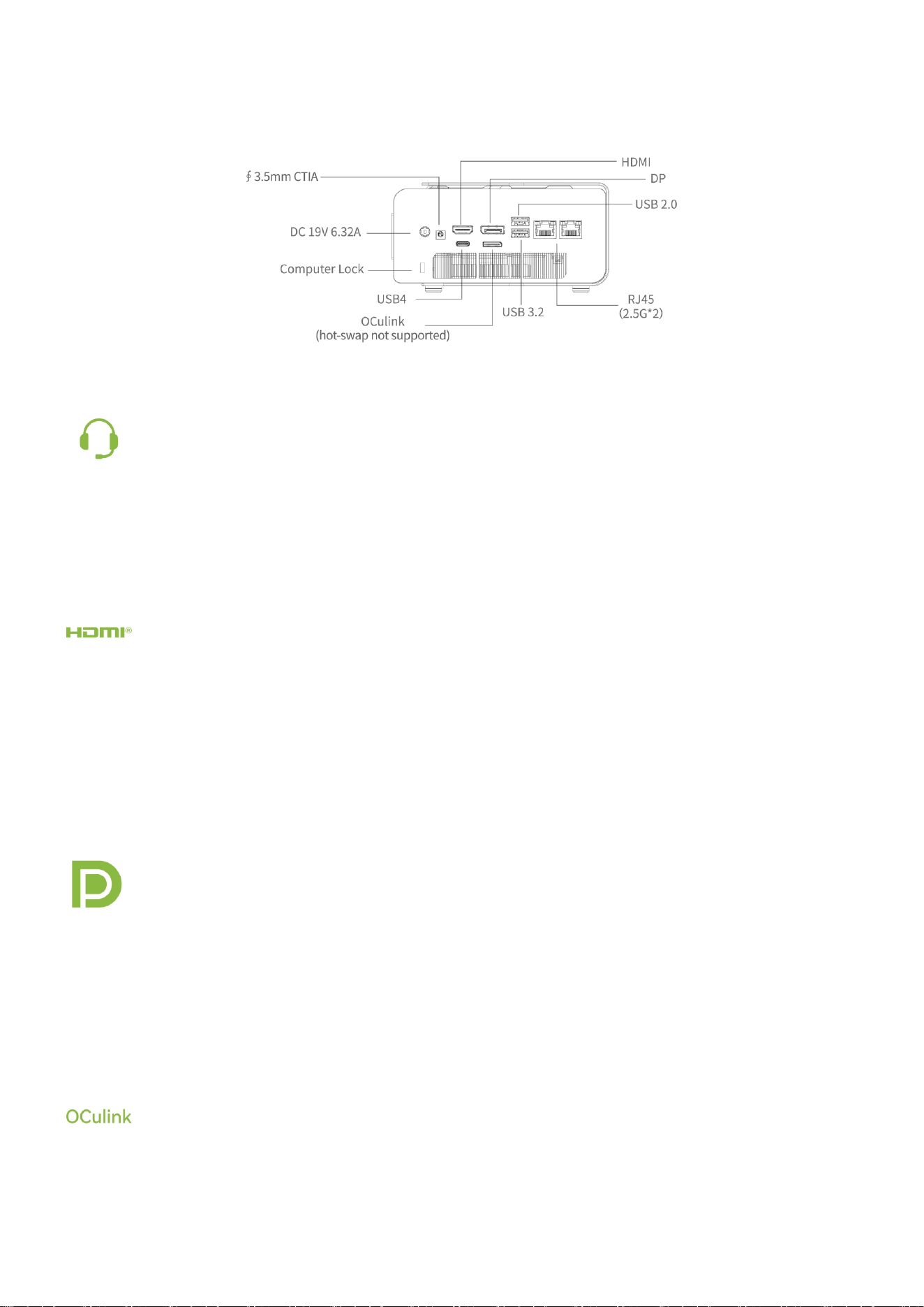
Back View
∮3.5mm CTIA Audio :
The port is used to connect audio output devices such as speakers or headphones. It can also be
used to connect external microphones or other audio output devices
HDMI
The HDMI port allows connection to Full HD displays for a superior viewing experience.
Note: As a display output port, this port supports up to 8K@60Hz resolution. Resolution may
vary depending on the cable and the connected display device.
DP
The DP port can connect to Full-HD display devices for an enhanced viewing experience.
Note: The maximum resolution for this port, when used as a display output source, supports up
to 8K @60Hz. Resolution may vary depending on the cable and output device.
OCulink
The OCuLink port can be used to connect external graphics card docks, external storage devices,
etc.

6
Note: The port does not support hot-swapping, so please plug and unplug it when the power is
off. Plug and unplugging it while the power is on may damage the motherboard.
USB2.0
The USB 2.0 port provides a transfer speed of up to 480 Mbps.
USB3.2 (Gen2)
The USB3.2 port provides a transfer speed of up to10 Gbps.
USB4
The fully-featured USB 4.0 port supports 40Gbps data transfer, PD power input (up to 100W),
and DP video output.
RJ45(LAN)
The network port supports a standard Ethernet cable to connect to a LAN.
DC IN
The power adapter converts AC power to DC power, which is supplied to your Mini PC via the
port. To avoid damaging your Mini PC,always use the included power adapter.
Important! The power adapter may heat up during operation.Please ensure it is not covered by
any objects and keep it away from your body.
Note:
The power adapter may vary depending on the model and region.Refer to the following
information for details:

7
120.08W power adapter: +19V DC⎓ 6.32A,120.08W
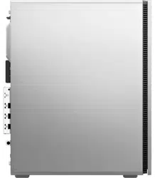
Computer lock
The port is designed for connecting a computer security lock to fix the host on a desktop or
cabinet, preventing theft and accidental movement.
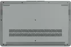
Ventilation Holes (Air Outlet)
Ventilation holes are located on the bottom, side of the lower chassis, and joints between top cover and
bottom chassis. Please refer to the actual product for details.
Important! Do not block any ventilation areas with paper, books, clothing, cables or other objects. Insufficient
air flow will lead to overheating, abnormal performance or device damage.

8
Technical specifications
MODEL
K12
CPU
Ryzen 200 Series, AMD Ryzen ™ 7 H 255;8-core 16 thread, Zen 4 processor
architecture;TSMC 4nm FinFET; Reference frequency 3.8G,MAX4.9G;
GPU
AMD Radeon™ 780M
Memory
2* DDR5 SO-DIMM dual channel 32GB 5600MT/s
(Product capacity is subject to actual purchase)
Storage
3*M.22280 PCIE4.0 SSD 512GB/1TB
(Product capacity is subject to actual purchase)
Network
WiFi
Wi-Fi 6E 802.11 a/b/g/n/ac/ax
Bluetooth
BT5.2
Ethernet
RJ45 2.5G*2
Power adapter
DC IN 19V 6.32A
Video Output
HDMI+DP+USB4+ TYPE-C
SIZE
154*151*73.6mm
Note: The pictures listed in this manual are for reference only.Product specifications/button definitions and
appearance are subject to change without further notice.
9
Using Your Mini PC
Connection Steps
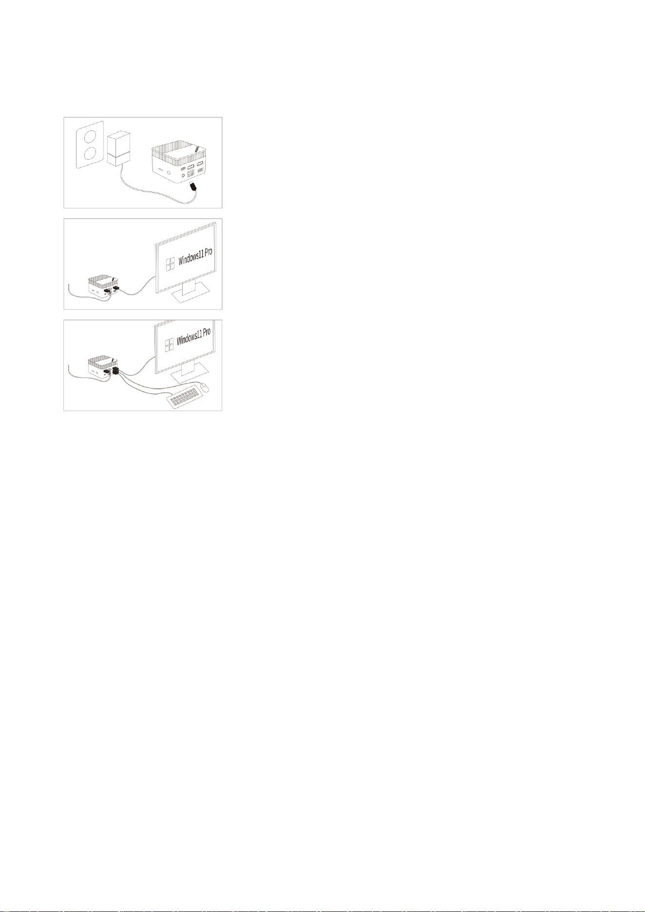
1.Please use the power adapter that comes with this product;
2. Connect the monitor with the HDMI cable please make sure that
the HDMI cable is qualified;
3. Connect the keyboard and mouse;
4. During the first system startup, please follow the Windows startup guide. During this process, remember
not to disconnect the power supply. It will take about ten minutes for the first startup to enter the user
desktop, please wait patiently;
5. Before the system startup process, please turn off WiFi and LAN and select the "skip option" to prevent
being unable to skip registration and log in to your personal account after connecting to the internet.
*Picture for reference only
Attached VESA Installation
Attach the VESA bracket (included in the package box) to the back of a monitor. This allows you to securely
hang the Mini PC on the back of the monitor, keeping your workspace tidy.

10
*Picture for reference only
1.Install the VESA mount bracket on the back of the Mini PC with a VESA hole.
2.Install the VESA mount bracket on the back of the monitor with a VESA hole.
Secure the bracket using the provided screws. while installing the VESA mount bracket.
Basic Setting
Entering the BIOS Settings
The BIOS (Basic Input/Output System) contains the hardware configuration settings necessary for starting
your Mini PC.
Under normal circumstances, the default BIOS settings are sufficient to ensure optimal system performance,
You should only modify the BIOS settings in the following scenarios:An error message appears during startup,
prompting you to access the BIOS settings.You need to configure or update the BIOS after installing new
system components.
Warning! Improper BIOS settings may result in system instability or failure to boot. It is strongly
recommended to make changes to BIOS settings only under the guidance of trained professionals.
In the shutdown state, press the power button, the button light will turn on,and then continuously click the
ESC key on the keyboard until the system BIOS interface - Aptio Setup AMI interface appears on the screen.

11
Instructions to Change Boot Mode to Auto Power On (Power On)
1.Enter BIOS
Press the ESC key repeatedly during system startup to enter the BIOS setup screen.
2.Go to Advanced
Use the right arrow key (→) to select the Advanced menu.
12
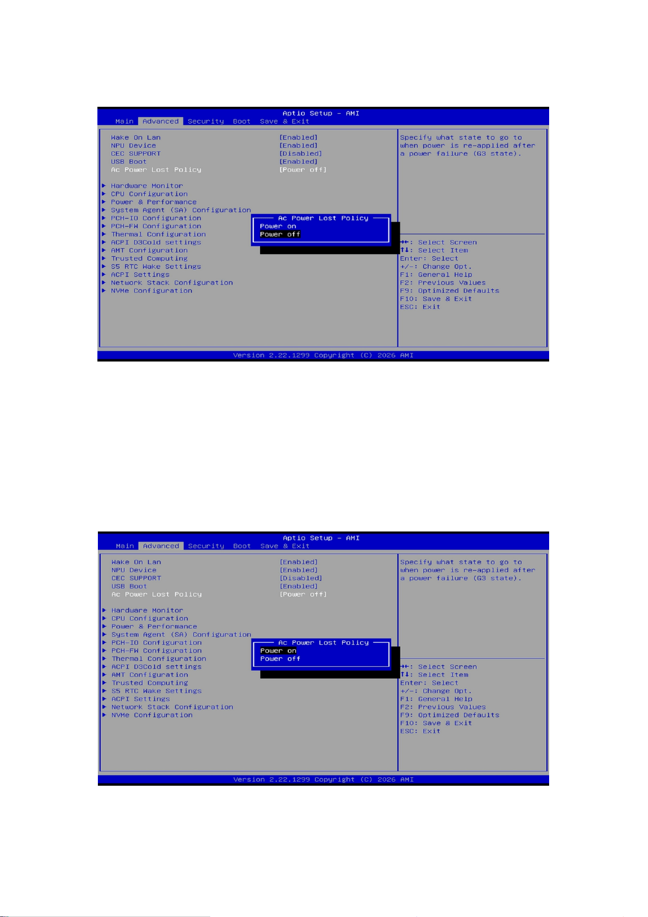
3.Select AC Power Lost Policy
Use the down arrow key (↓) to highlight AC Power Lost Policy.
4.Change the AC Power Lost Policy Value
Press Enter to open the sub menu. Use the down arrow key (↓) to cycle through the power‑on modes:
Power off – The system requires pressing the power button to start.
Power on – The system turns on automatically when AC power is restored.
(Factory default is Power off.)
13
5.Select Power On
Choose Power On and press Enter to confirm.
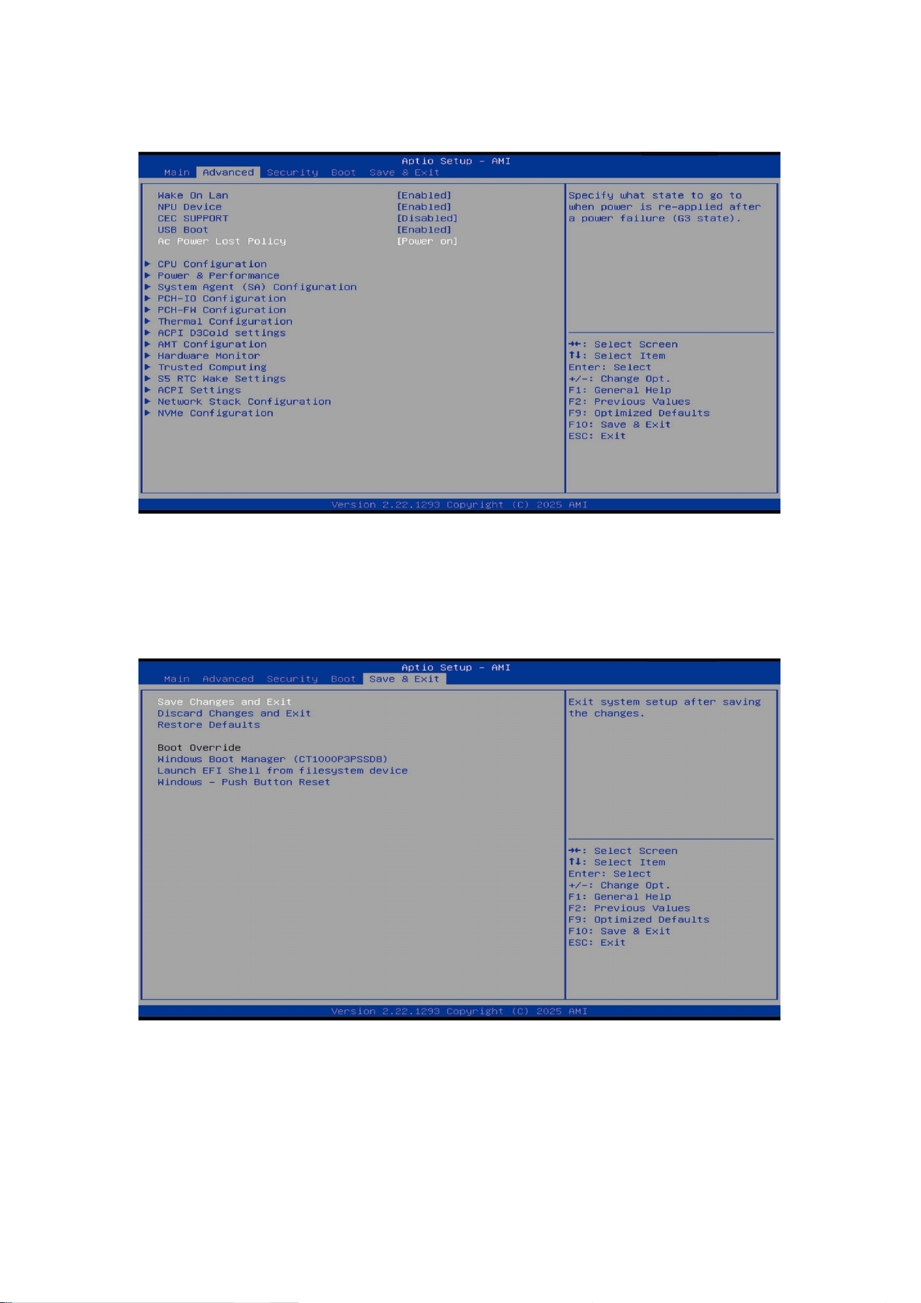
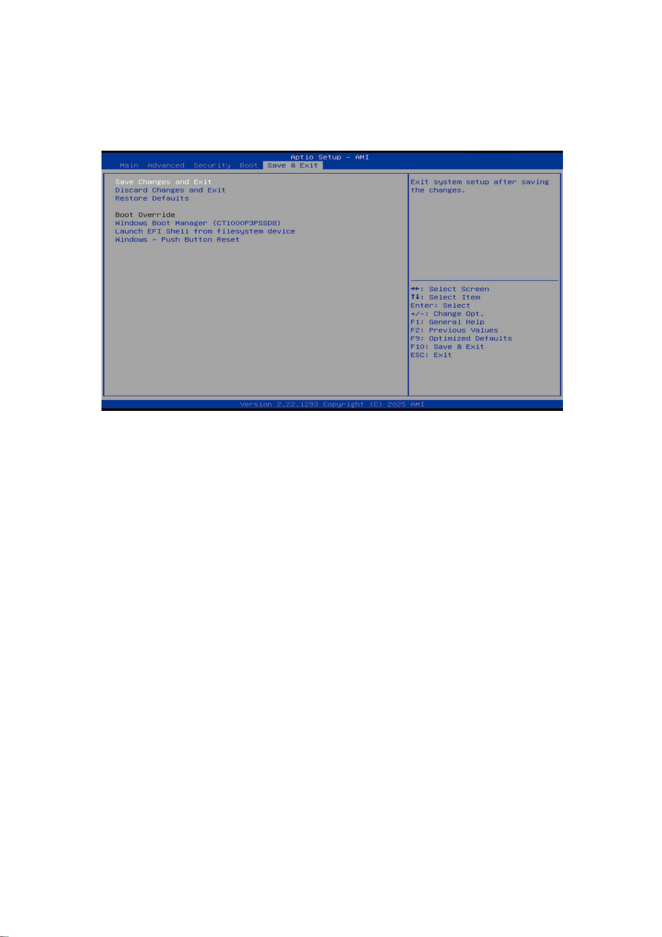
6.Save Changes and Exit
Use the right arrow key (→) to switch to the Save & Exit screen. Select Save Changes and Exit and press Enter
to save the settings and exit BIOS.
After completing the above steps, the system will start automatically when AC power is applied (auto power
on).
14
Instructions to Configure Wake-On-LAN
1.Enter BIOS
Press the ESC key repeatedly during system startup to enter the BIOS setup screen.
2.Go to Advanced
Use the right arrow key (→) to select the Advanced menu.
15
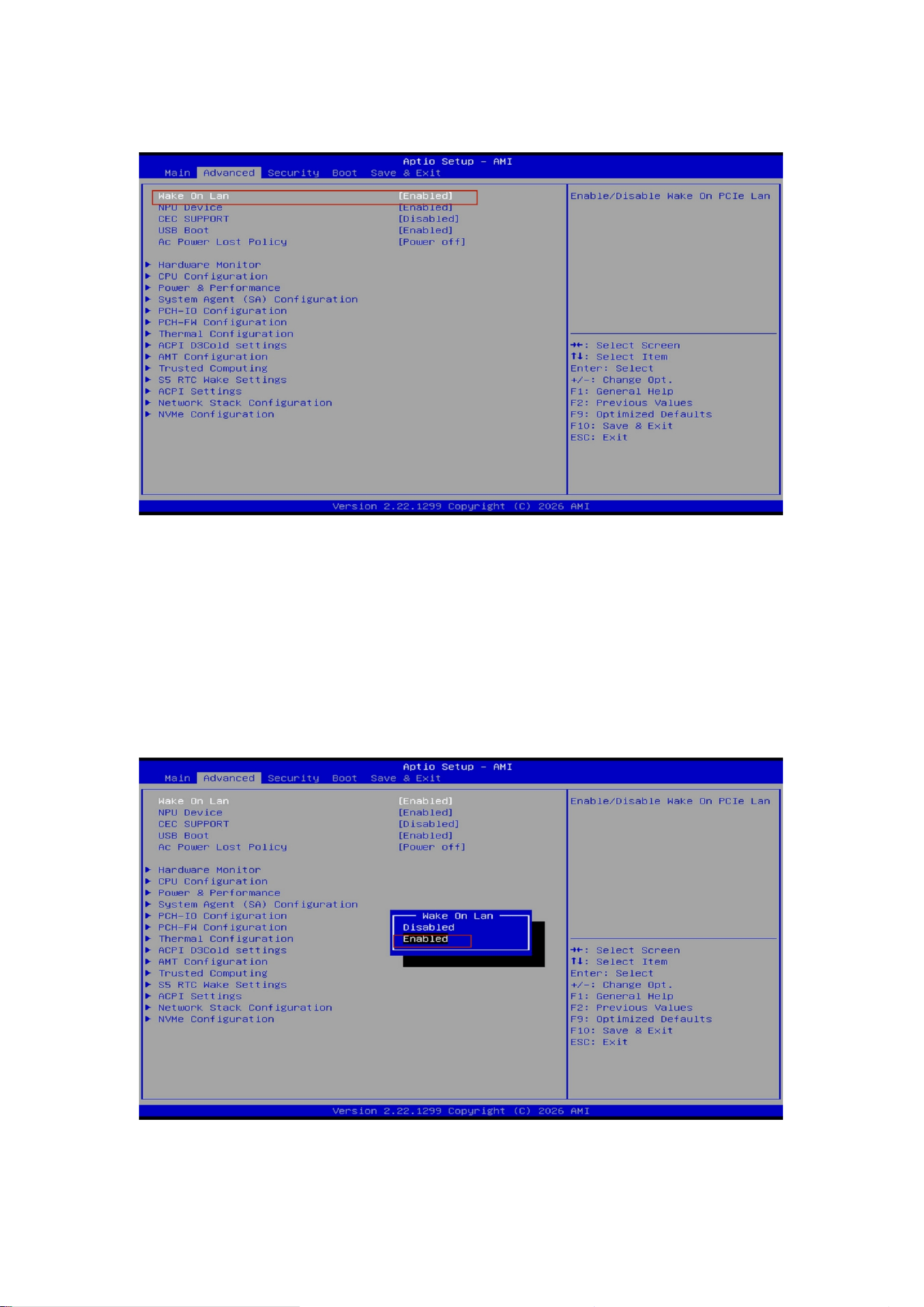
3.Select Wake On Lan
Highlight Wake On Lan using the down arrow key (↓).
4.Change the Wake On Lan Value (default: Enabled)
Press Enter to open the sub menu. Use the down arrow key (↓ ) to toggle between the Wake ‑On ‑ LAN
modes:
Disabled – Wake‑On‑LAN is turned off.
Enabled – Wake‑On‑LAN is turned on.
16
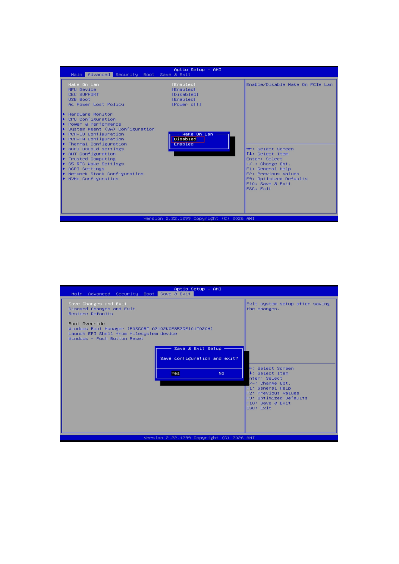
5.Select the desired mode – e.g., Disabled
Choose Disabled (to turn off Wake‑On‑LAN) and press Enter to confirm.
6.Save Changes and Exit
Use the right arrow key (→) to switch to the Save & Exit screen. Select Save Changes and Exit and press Enter
to save the settings and exit BIOS.
After completing the above steps, the Wake‑On‑LAN setting will be configured as selected.
17
Instructions to Configure Thermal Power Mode
1.Enter BIOS
With the device connected to power and turned off, briefly press the power button to start the system.
During startup, press the ESC key repeatedly to enter the BIOS setup screen.
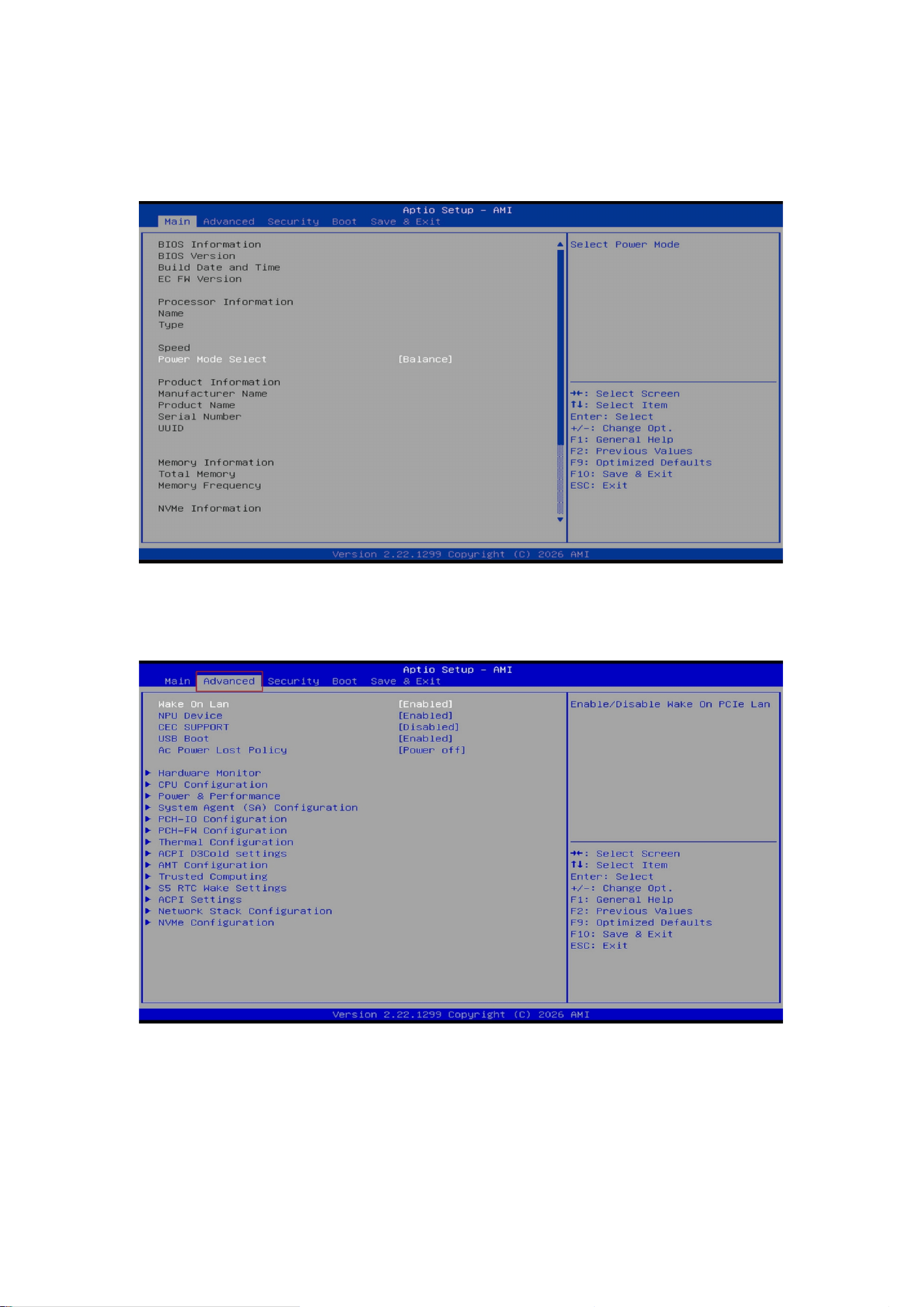
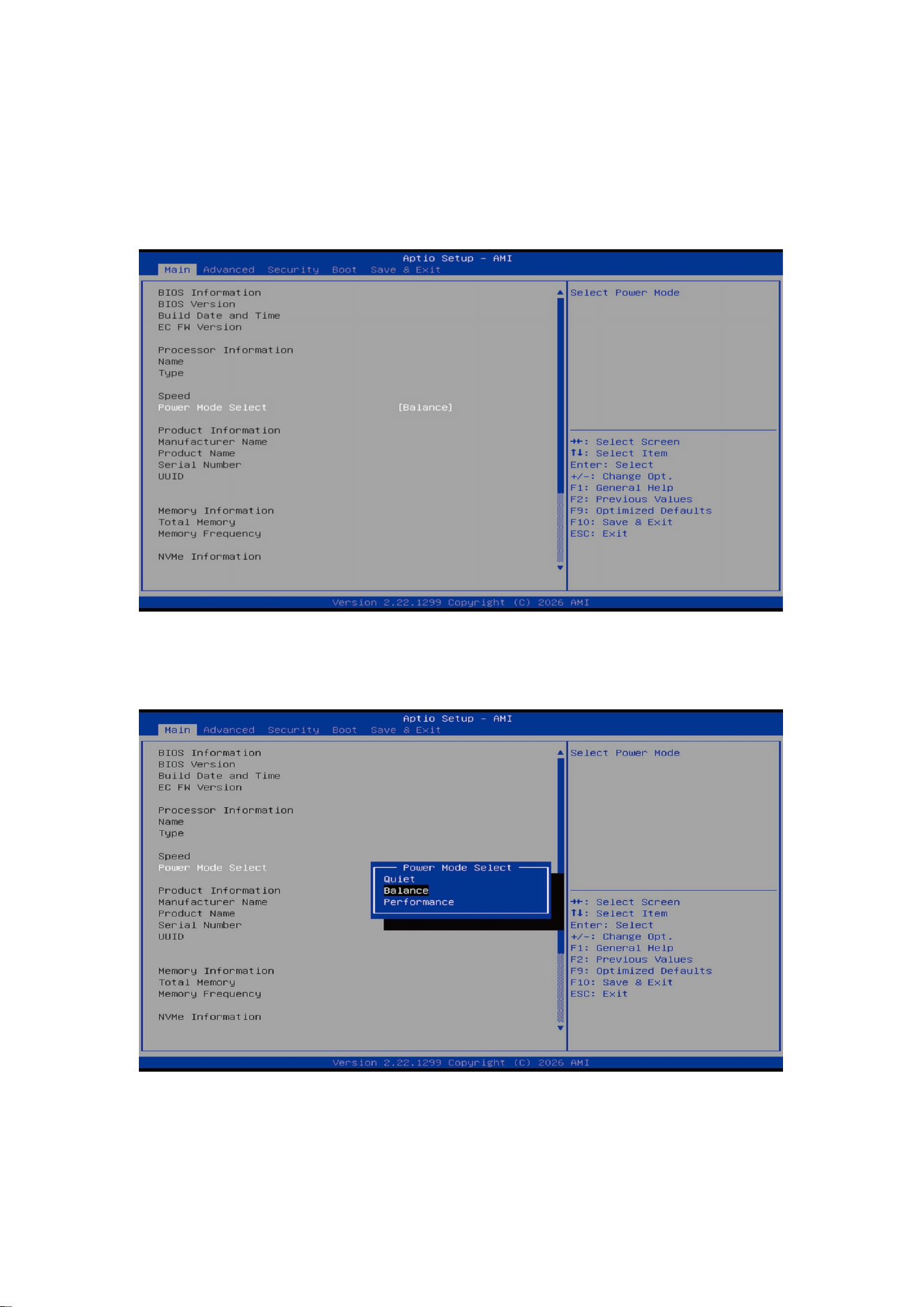
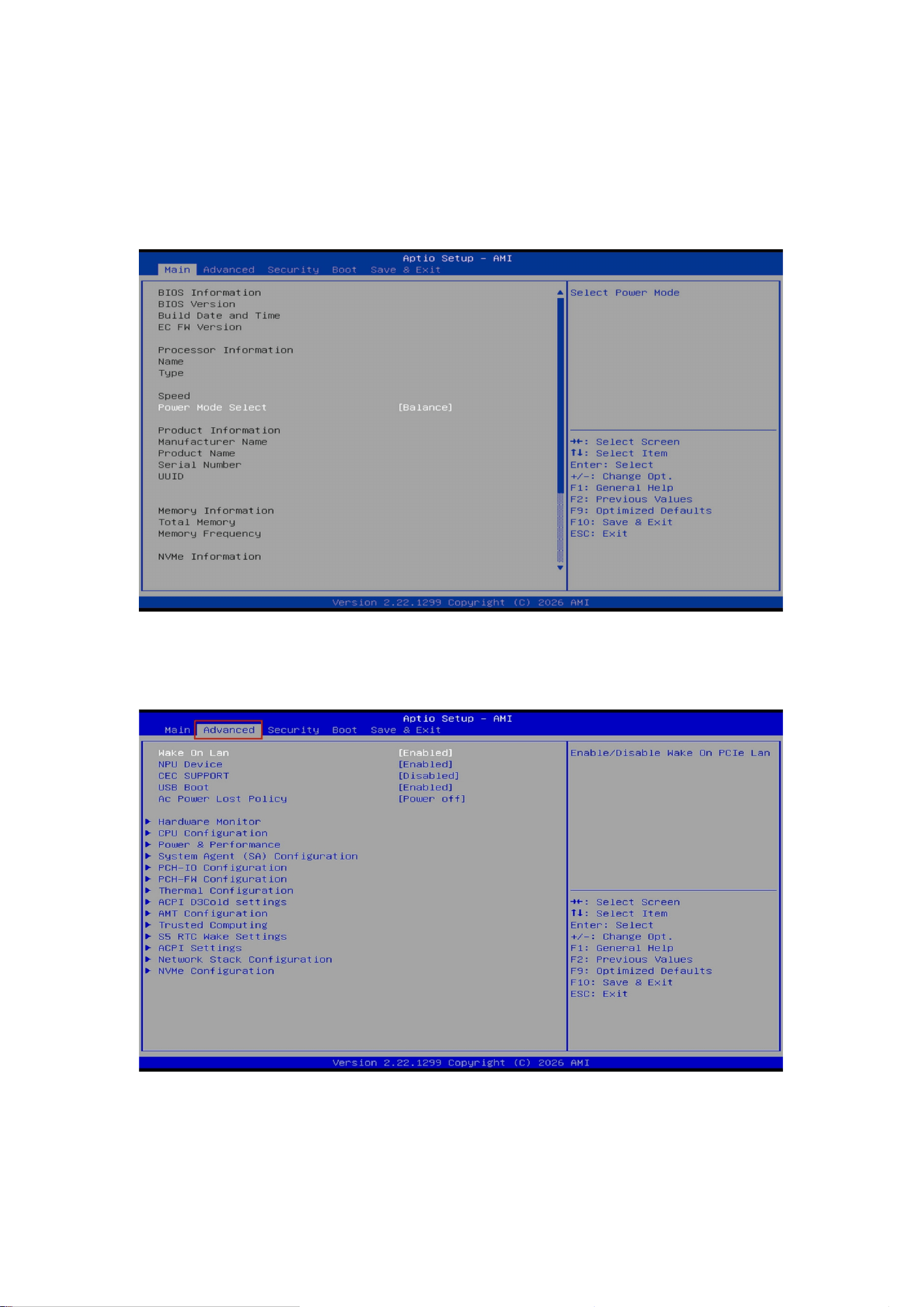
2.Select Power Mode Select
Use the arrow keys to highlight Power Mode Select and press Enter.
18
3.Change the Power Mode Select Value
Users can adjust the thermal power mode according to their needs (factory default: Balance). Use the down
arrow key (↓) to cycle through the available modes.
Note:
Quiet – Silent mode;Balance – Balanced mode;Performance – Performance mode
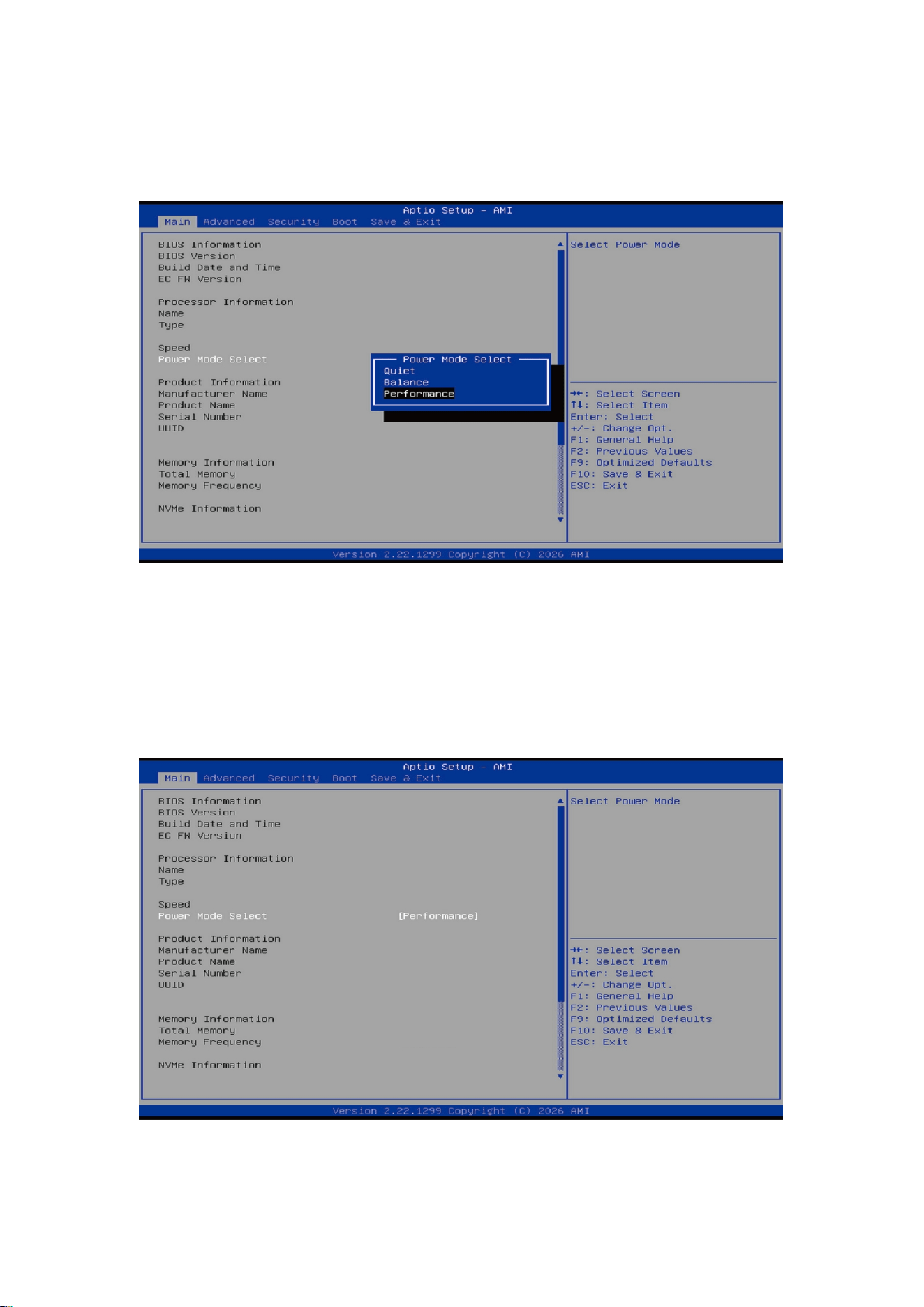
4.Select the desired thermal power mode
Press Enter to confirm the selected mode.
19
5.Save Changes and Exit
Use the right arrow key (→) to switch to the Save & Exit screen. Select Save Changes and Exit and press Enter
to save the settings and exit BIOS.
c
After completing the above steps, the thermal power mode will be successfully changed.
20
Instructions to Configure Fan Speed
1.Enter the BIOS Interface
With the device connected to power and turned off, briefly press the power button to start the system.
During startup, press the ESC key repeatedly to enter the BIOS setup screen.
2.Go to the Advanced Interface
Use the right arrow key (→) to select the Advanced menu.
21
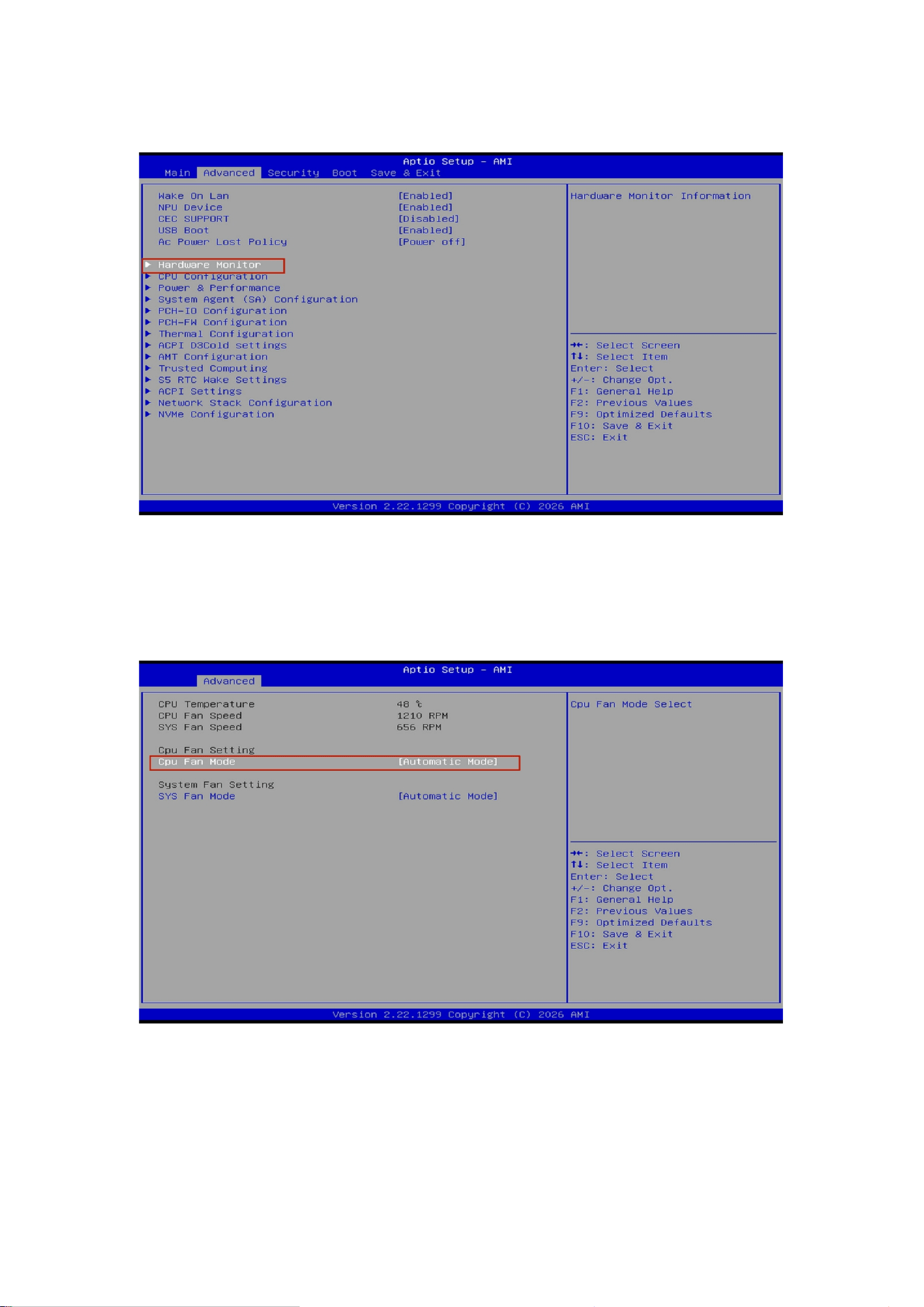
3.Select Hardware Monitor
Use the down arrow key (↓) to highlight Hardware Monitor and press Enter.
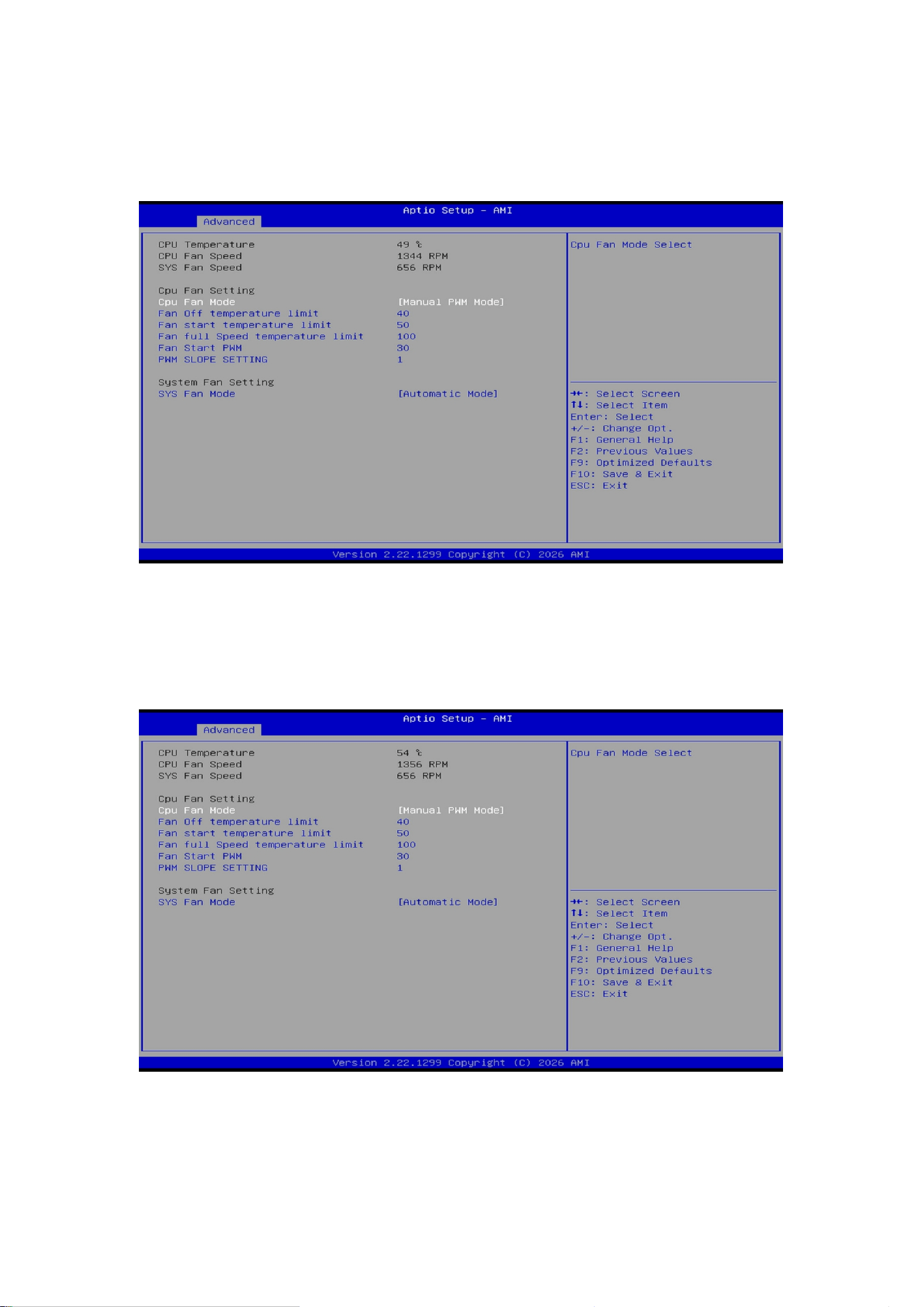
4.Access Hardware Monitor Items
Once inside the Hardware Monitor menu, you can view the current fan speeds and adjust the speeds of one
CPU fan and one system fan. Select CPU Smart Fan Configuration and press Enter.
22
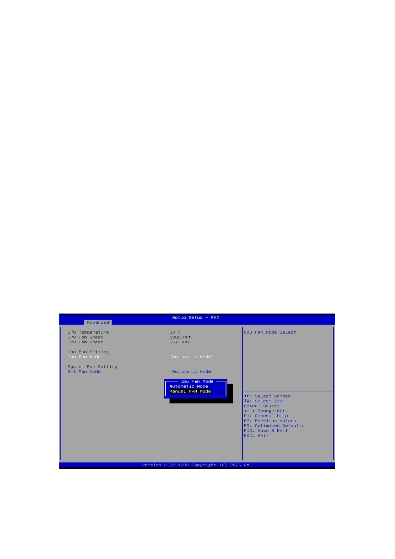
5.Set the CPU Fan Mode Option
Press Enter to open the sub menu. Use the down arrow key (↓) to toggle the CPU Fan Mode options:
Manual PWM Mode – Manually adjust the fan duty cycle.
Automatic mode – The fan speed is automatically controlled.
Available parameters:
Fan OFF temperature limit – Temperature at which the fan stops.
Fan Start temperature limit – Temperature at which the fan starts.
Fan Full Speed temperature limit – Temperature at which the fan runs at full speed.
Fan Start PWM – Initial duty cycle (set value × 100%).
PWM SLOPE SETTING – Slope of the PWM curve.
Note:
Final fan speed = Maximum fan speed × PWM duty cycle.
PWM duty cycle = [Initial duty cycle set value + (Current device temperature – Fan start temperature) ×
PWM slope setting] × 100%.
23
6.Modify the Fan Start Temperature Limit Value
You can manually enter a value or press Enter and then use the +/- keys to adjust the Fan Start temperature
limit value. This value sets the lowest starting temperature for full‑speed operation.
7.Modify the Fan Start PWM (Initial Duty Cycle) Value – Not Recommended
Manually adjust the Fan Start PWM value (set value × 100%). This value determines the percentage of fan
speed (Maximum fan speed × (set value × 100%)).
24
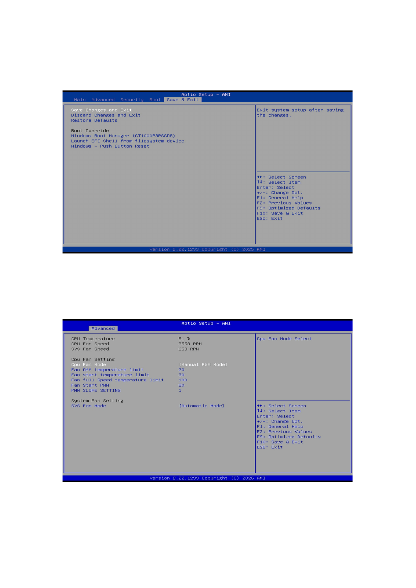
8.Save Changes and Exit
Use the right arrow key (→) to switch to the Save & Exit screen. Select Save Changes and Exit and press Enter
to save the settings and exit BIOS.
9.Verify the Fixed Fan Speed Setting
Press ESC to return to the Hardware Monitor page and check whether the CPU fan speed has been
successfully modified.
After completing the above steps, the fan speed will be successfully changed.

25
Upgrading Your Mini PC
Important Notice!
We recommend that you perform the installation or upgrade of your mini PC under the guidance of a
professional. For further assistance, please visit an authorized GMK service center.
Before beginning the installation, please ensure that your hands are dry. Prior to installation, please wear an
anti-static wrist strap or touch a grounded object or metal surface to prevent electrostatic discharge from
damaging the components.
Note: The illustrations in this chapter are for reference purposes only. The appearance of the slots may vary
depending on the specific model.
Disassembly Method
The device features a screw-secured structural design; the top cover can only be opened after the securing
screws have been removed.
Removing the Top Cover
1. Shut down your mini PC and disconnect all cables and external peripherals.
2. Place the mini workstation on a stable, flat surface, ensuring that the top side of the device is facing
downward.
3. Remove the four securing screws located on the bottom of the device (these screws are fitted with rubber
feet), then lift off the outer metal mid-frame.
4. Keeping the device bottom-side down, unscrew the screws securing the fan bracket, then gently lift the
bracket upward to remove it.
5. Once you have completed the device upgrade procedures, reverse these steps to reinstall the fan bracket,
the metal mid-frame, and the bottom securing screws to complete the reassembly process.
Precautions

26
1. When installing or removing the fan bracket, apply moderate force to avoid damaging the fan cables.
2. After completing the reassembly, be sure to check the interior of the product for any stray screws or other
foreign objects; ensure that the top cover is seated firmly against the bottom casing before connecting the
power supply and booting up the device.
3. Removing other internal components may void the warranty.
27
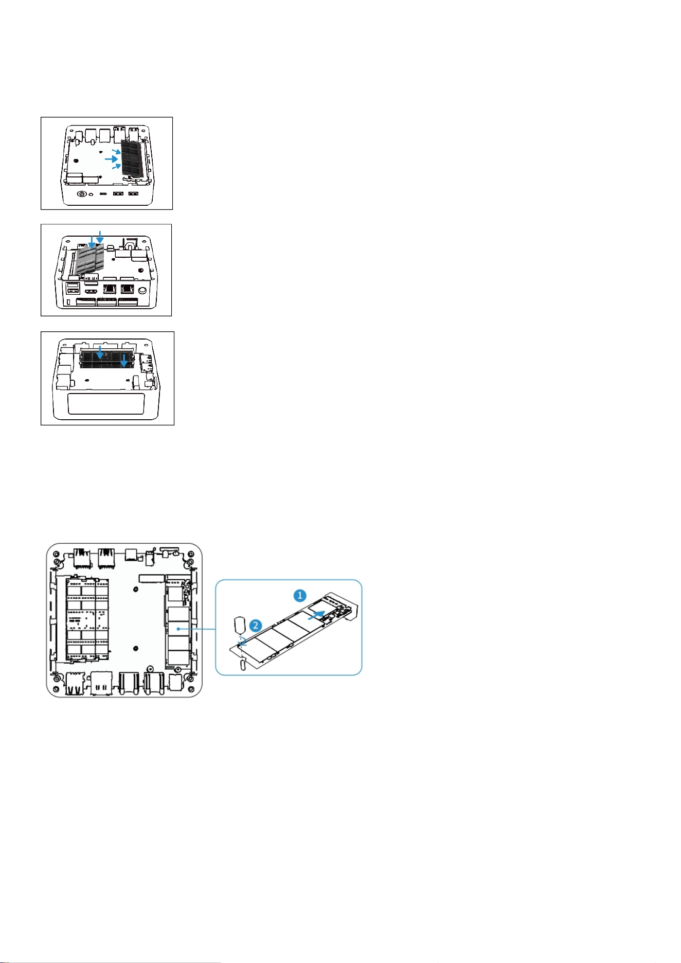
Installing Memory Modules
Your Mini PC is equipped with two SO-DIMM slots, allowing the installation of up to two memory modules.
1. Align the memory module with the slot and insert it.
2. Press the memory module down gently until it clicks into place.
3. Repeat the same steps to install additional memory modules.
*Picture for reference only
Installing M.2 SSDs
Your mini PC has multiple M.2 slots inside. (The exact number depends on the device you actually purchase.).
*Picture for reference only
Install the M.2 SSD to the Mini PC:
1.Align the M.2 SSD with slots and insert it.
2.Gently push the M.2 SSD downward onto the standoff,then use one of the included screws to secure it.3.
Repeat the same steps to install another M.2 SSD if needed.
28
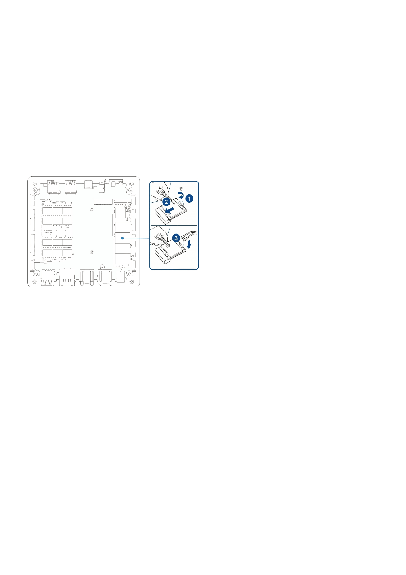
Installing a Wireless Network Card
1. Gently push the wireless network card downward onto the standoff, then use the included screw to secure
it.
2. Attach the antenna to your wireless network card.
Notes:
Connecting an antenna to your wireless network card can enhance the wireless signal.
A soft click sound indicates that the antenna is securely connected to the wireless network card.
*Picture for reference only

29
Certification & Compliance
FCC Compliance Statement
This device complies with part 15 of the FCC Rules. Operation is subject to the following two conditions:
(1) This device may not cause harmful interference.
(2) This device must accept any interference received, including interference that may cause undesired
operation.
Any changes or modifications not expressly approved by the party responsible for compliance could void the
user's authority to operate the equipment.
Note: This equipment has been tested and found to comply with the limits for a Class B digital device,
pursuant to part 15 of the FCC Rules.These limits are designed to provide reasonable protection against
harmful interference in a residential installation. This equipment generates uses and can radiate radio
frequency energy and, if not installed and used in accordance with the instructions, may cause harmful
interference to radio communications. However, there is no guarantee that interference will not occur in a
particular installation. If this equipment does cause harmful interference to radio or television reception,
which can be determined by turning the equipment off and on, the user is encouraged to try to correct the
interference by one or more of the following measures:-Reorient or relocate the receiving antenna.-Increase
the separation between the equipment and receiver.-Connect the equipment into an outlet on a circuit
different from that to which the receiver is connected.-Consult the dealer or an experienced radio/TV
technician for help.
EU Declaration Of Conformity
We, Shenzhen GMK Technology Co., Ltd.
Address: Floor 9, No.2 Building, Yingtai Kehui Plaza, No.8 Yingtai Road,Langkou Community, Dalang Street,
Longhua District, Shenzhen City,Guangdong Province China 518109

30
Model Number: K12
Complies with the following EU Directives:
Electromagnetic Compatibility Directive (2014/30/EU)
Low Voltage Directive (LVD) 2014/35/EU
Restriction of Hazardous Substances (RoHS) Directive (2011/65/EU), (2015/863/EU)
Radio Equipment Directive (RED) (2014/53/EU)
Harmonized Standards Applied:
1.Low Voltage Directive (LVD) 2014/35/EU
EN IEC 62368-1:2020+A11:2020 (Safety of IT/AV equipment)
EN IEC 62311:2020 (EMF exposure limits)
2.Electromagnetic Compatibility (EMC) Directive 2014/30/EU
EN 55032:2015/A11:2020 (Emissions)
EN 55035:2017/A11:2020 (Immunity)
EN IEC 61000-3-2:2019/A1:2021 (Harmonics)
EN 61000-3-3:2013/A2:2021 (Voltage fluctuations)
3.Radio Equipment Directive (RED) 2014/53/EU
EN 300 328 V2.2.2 (2019-07) (2.4 GHz band, e.g., Wi-Fi/Bluetooth)
EN 301 893V2.1.1 (2017-05) (5 GHz band, e.g., Wi-Fi5/6)
EN 301 489-1 V2.2.3 (2019-11) (General EMC for radio equipment)
EN 301 489-17 V3.3.1 (2024-09) (2.4/5 GHz specific EMC)EN 18031-1:2024
EN 18031-2:2024
4.Restriction of Hazardous Substances (RoHS) Directive 2011/65/EU
IEC 62321 Series (Testing for restricted substances):

31
IEC 62321-3-1:2013 (Lead, mercury, cadmium screening)
IEC 62321-5:2013 (Cr6and PBB/PBDE)IEC 62321-4:2013 + AMD1:2017 CSV (Hg in polymers/electronics)
IEC 62321-6:2015 (Phthalates in plastics)
IEC 62321-7-1:2015 (Hexavalent chromium)
IEC 62321-7-2:2017 (Br/Cl in polymers)
IEC 62321-8:2017 (Phthalates in coatings)
This product is marked with the CE symbol to confirm compliance with EU regulations.
The aforementioned product meets all essential requirements of the applicable EU directives. The full
technical documentation, including test reports and risk assessments, is retained and available for inspection
by relevant authorities for 10 years after market placement.
Signed for and on behalf of: Shenzhen GMK Technology Co., Ltd. Compliance Officer 2024-04-17 Shenzhen,
China

32
Appendix
Safety Warnings and Precautions
Please read and observe the following precautions carefully before using the device to avoid bodily injury,
equipment damage or abnormal operation.
Use Environment
Keep the device away from dusty, humid or extreme temperature environments.
Operating temperature: 0°C – 40°C; relative humidity: 10%–90% RH (non-condensing).
Do not place near heat sources such as radiators or heaters.
Do not place on uneven or unstable surfaces. Use the dedicated stand if provided.
Maintain sufficient ventilation space around the device for heat dissipation. Keep paper scraps, screws, wires
and other small objects away from ports and openings to prevent short circuits.
Power Safety
Use only the original power adapter specified for this product. Using an incompatible adapter may damage
internal components.
Waterproof
This device is not waterproof. Keep it dry at all times.
Operation & Maintenance
Do not insert sharp or foreign objects into any openings or internal parts of the device to avoid short circuits
or circuit damage.
Do not drop, bump or violently shake the device.
Keep the ventilation area at least 20 cm away from your body during installation or operation.
All maintenance and repair services must be performed by authorized service personnel. Do not disassemble
or modify the device by yourself.

33
Usage Precautions
Before use, please check that all components are functioning properly and that the power cable is not
damaged or improperly connected.
Keep the product in a dry environment. Rain, moisture, and liquids containing minerals can corrode the
electronic circuits. To avoid potential electric shock damage, always unplug all power cables from the power
socket before cleaning or moving the product.
If you encounter any of the following issues, or any technical problems while using the product, please
contact your authorized distributor.
-Damaged power cable or charger.
-The computer or accessories have been exposed to water.
-The computer does not operate normally despite following the instructions.
-The computer has been dropped or the chassis is damaged.
-The computer’s performance is abnormal.
Lithium Battery Safety Warning
Replacing the battery incorrectly could cause an explosion. Please follow the manufacturer’s instructions and
use the same type or model of battery. Also, dispose of used batteries according to the manufacturer's
instructions.
Do Not Disassemble or Reassemble Yourself Warning
Do not disassemble or repair the product yourself. Any unauthorized disassembly will void the warranty.
34
Service and Support
Please visit our multilingual websites:
Web: www.gmktec.com
Facebook: @gmktecdotcom
Twitter: @gmktecdotcom
Instagram: @gmktec_official
After Service
Email: support@gmktec.com
Sales: gmk@gmktec.com