Malibu M-Link by Wet Sounds
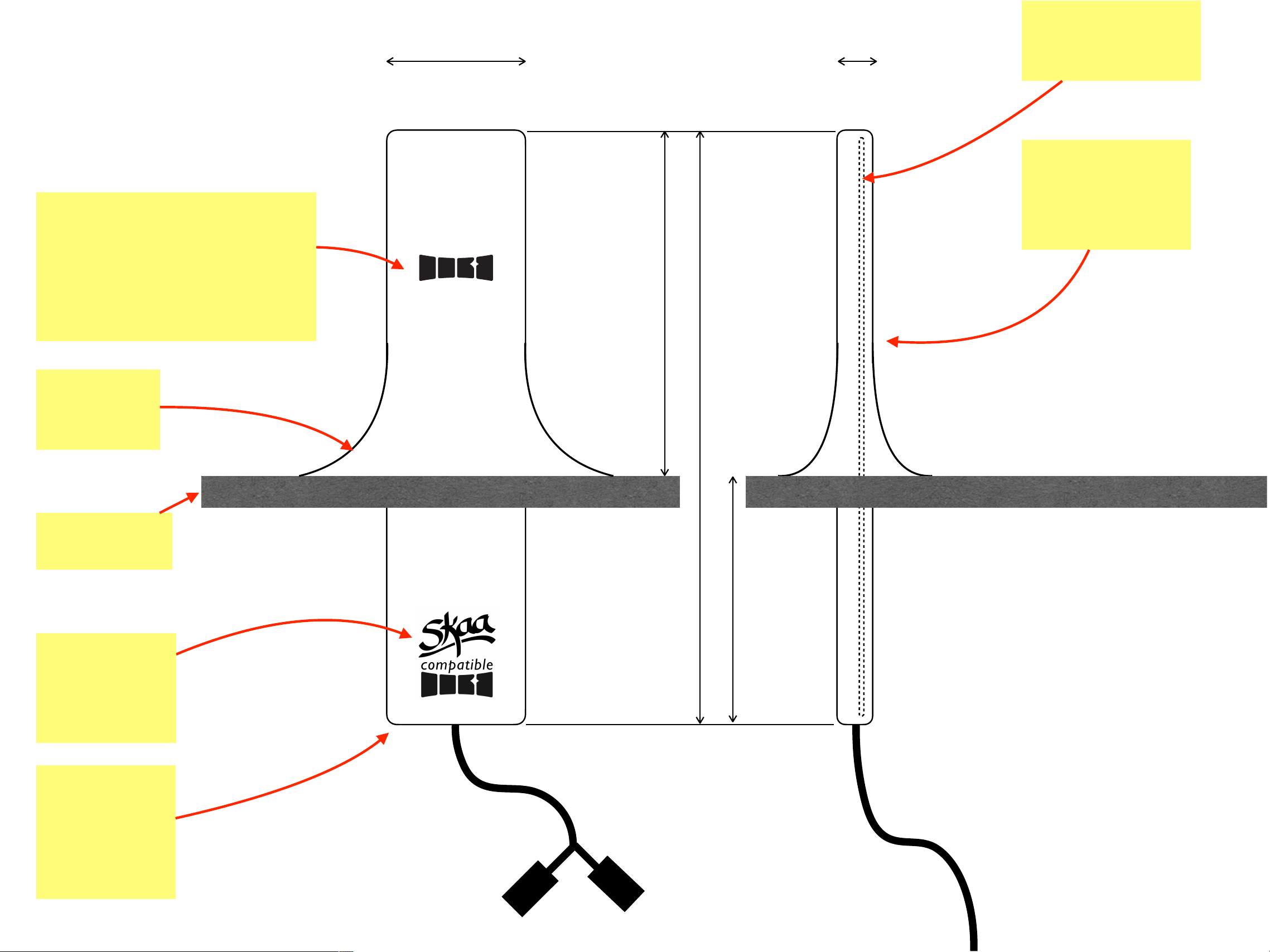
Mech Overview
Eleven Engineering Inc.
071023
Front View Side View
120 mm
Motherboard w/FE
antenna in upper
section
SKAA
compatible
badge on lower
enclosure
No metal parts
allowed in top half
of product (the
antenna region)
10 mm30 mm
SKAA Icon on M-Link upper
enclosure— can be subtle for
example gloss black on matte
black — for detailed dimension
and location requirements see
DO5501 SKAA Standard Rules
160 mm pigtail
DT04-4/p
connector
Flair with
weatherproof
seal to deck
Boat’s Bow
Deck
CANBUS and Power
70 mm
50 mm
Notes
•
The I/O jacks are DT04-4/p and DT04-6/p
from brand TE Connectivity
•
If possible, some jacks will be combined/
eliminated; for example if power for M-Link
can be drawn from the CANBUS network
connection, the power connection to the M-
Link will be removed
•
This sketch is NOT meant to represent the
Industrial Design for the M-Link —that ID
will be integrated into the product design
during Beta development phase
•
Rather this sketch defines the overall mech
configuration and the minimum dimensions
M-Link I/O jacks
(100%
waterproof jack
solution is
required)
160 mm pigtail to 2 jacks
DT04-6/p
connector
4 audio channels (2 in 2 out)
and shared ground for each
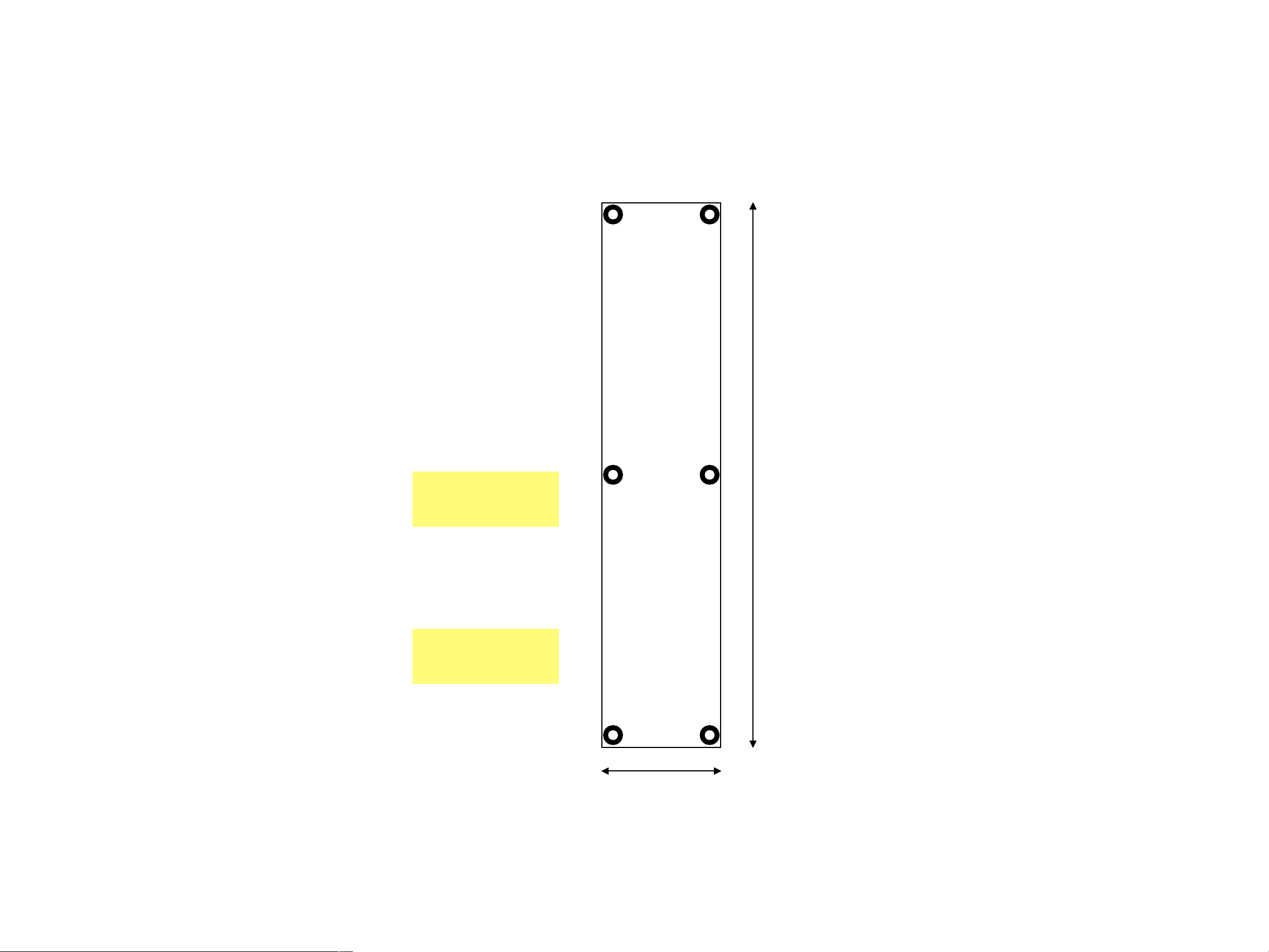
Malibu M-Link by Wet Sounds
Motherboard PCB dimensions
Eleven Engineering Inc.
061923
110.0 mm
PCB is 1.6 mm
thick
24.0 mm
All components
one side
OFF
TRANSMIT RECEIVE
Marty’s Leviathan
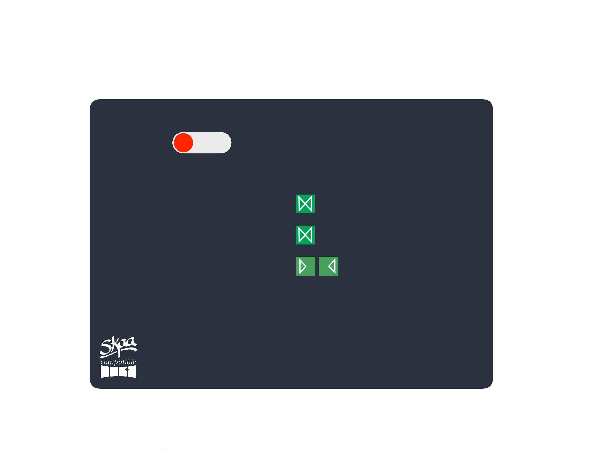
Malibu M-Link by Wet Sounds
MFD Software UI - Transmit Mode
Eleven Engineering Inc.
071023
Sabine’s Nazomi
the Kraken
Jim’s Speaker Pair
4 Receivers are Bonded:
Notes
•
This is the MFD screen when the M-Link is
in Transmit mode
•
Global Volume for the M-Link (SKAA API
hVOL) is always fixed at “full up” (0xFF).

OFF
TRANSMIT RECEIVE
Malibu M-Link by Wet Sounds
MFD Software UI - Mode = OFF
Eleven Engineering Inc.
063023
Notes
•
This is the MFD screen when the M-Link is
set to OFF
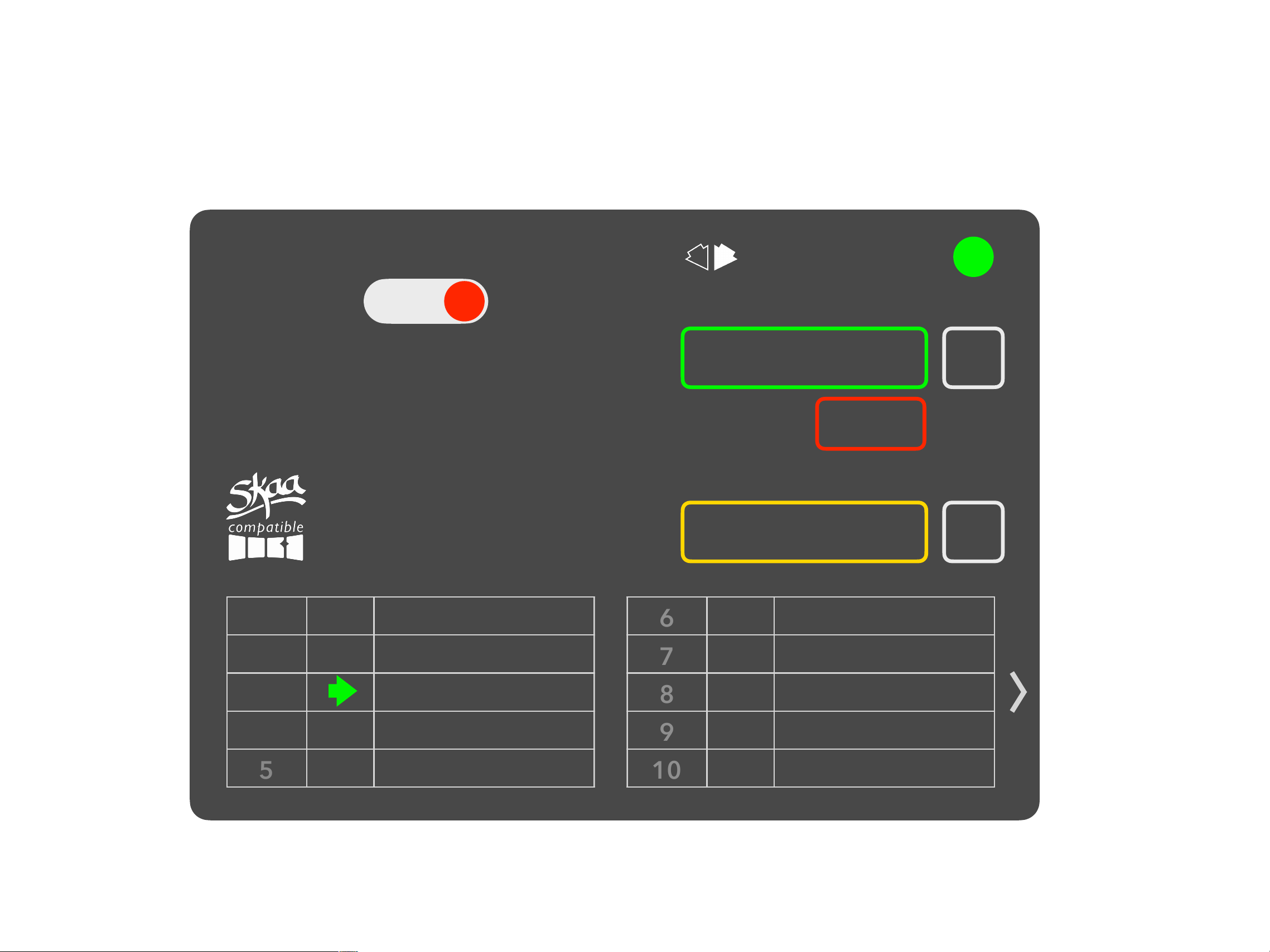
Malibu M-Link by Wet Sounds
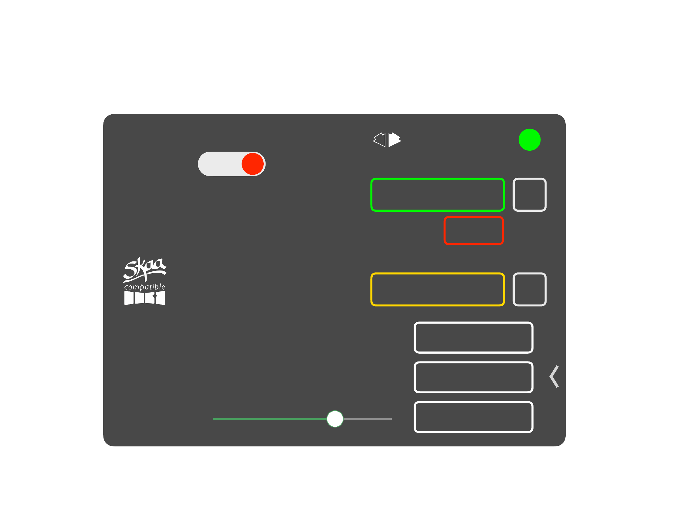
MFD Software UI - Receive Mode
Eleven Engineering Inc.
062823
Hunt
—
Favorites
Explore
New
+
Swing
OFF
TRANSMIT RECEIVE
Marty’s Leviathan
Bonded to favorite 3
1
Wake Up
2
the Kraken
3
Sabine’s Nazomi
4
Hammer Cruz
5
6
7
8
9
10
Notes
•
This is the MFD screen when the M-Link is
in Receive mode
•
Specifically, this is what the screen looks
like BEFORE the chevron (bottom right) is
clicked
Hunt
—
Favorites
Explore
New
+
Swing
OFF
TRANSMIT RECEIVE
Marty’s Leviathan
Bonded to favorite 3
Mute / Unmute
Malibu M-Link by Wet Sounds
MFD Software UI - Receive Mode (page 2)
Eleven Engineering Inc.
071023
Volume
Factory Reset
Cluster Up
Notes
•
This is the MFD screen when the M-Link is
in Receive mode
•
Specifically, this is what the screen looks
like AFTER the chevron (bottom right) is
clicked
•
The chevron reveals power user feature
buttons plus a local SKAA volume fader
•
Factory Reset will max bVTR
•
bVTR will also be set to max on Power Up
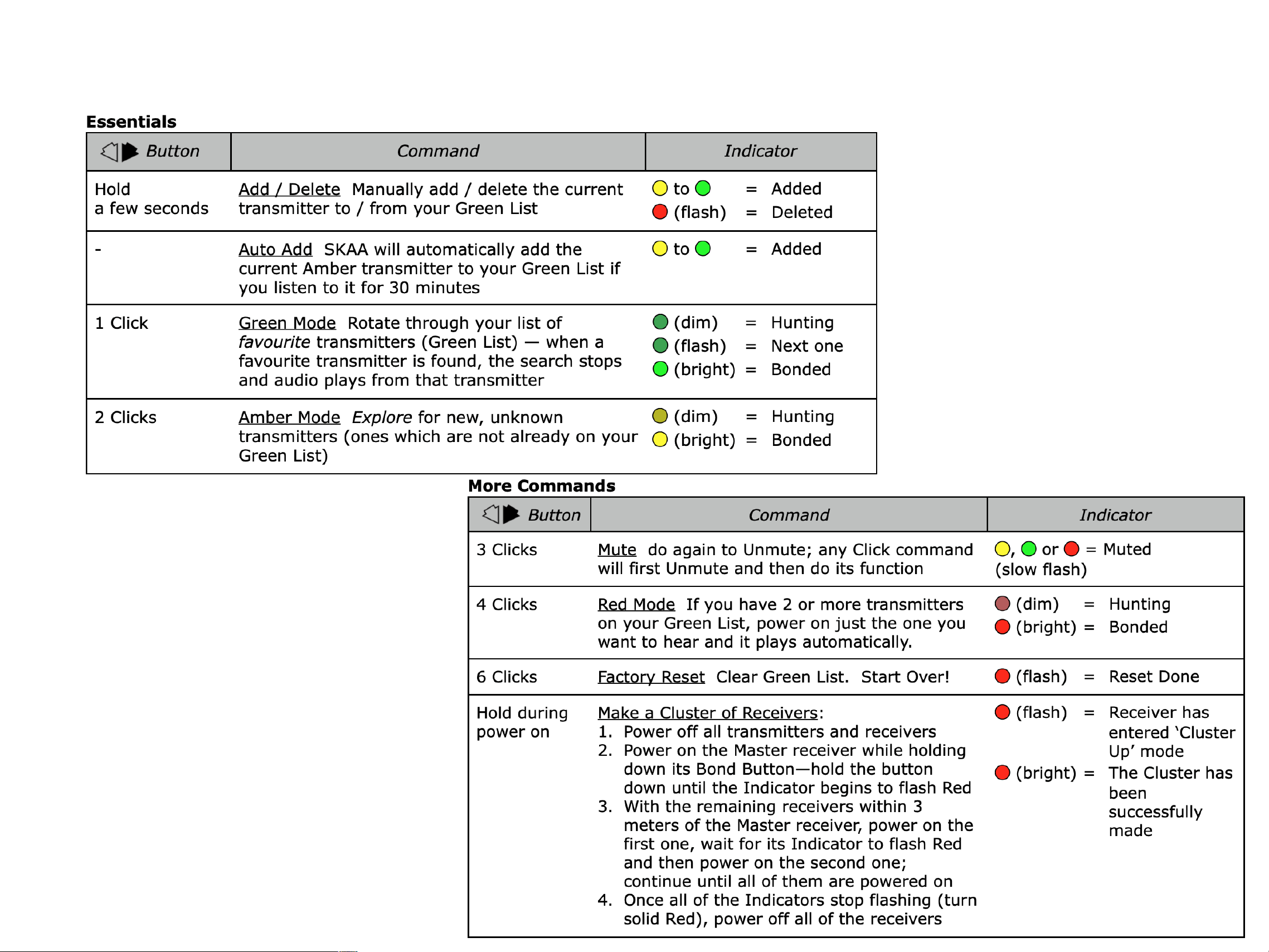
Bond Button / Bond Indicator
Standard Definition
Eleven Engineering Inc.
Notes
•
In the MFD software UI, most of the multi-
click Bond Button functions have a
dedicated button (Receive mode only)
•
A fully spec-compliant Bond button is also
implemented to spec in the software UI
(Receive mode only)

FCCStatement
Thisdevicecomplieswithpart15oftheFCCrules.Operationissubjecttothefollowingtwoconditions:(1)thisdevicemaynotca
useharmfulinterference,and(2)thisdevicemustacceptanyinterferencereceived,includinginterferencethatmaycause
undesiredoperation.Changesormodificationsnotexpresslyapproved
bythepartyresponsibleforcompliancecouldvoidtheuse
r’sauthoritytooperatetheequipment.
NOTE:ThisequipmenthasbeentestedandfoundtocomplywiththelimitsforaClassBdigitaldevice,pursuanttopart15oftheF
CCRules.Theselimitsaredesignedtoprovidereasonableprotection
againstharmfulinterferenceinaresidentialinstallation.This
equipmentgeneratesusesandcanradiateradiofrequencyenergyand,ifnotinstalledandusedinaccordancewiththeinstructio
ns,maycauseharmfulinterferencetoradiocommunications.However,thereisnoguaranteethatinterferencewillnotoccurina
particularinstallation.If
thisequipmentdoescauseharmfulinterferencetoradioortelevisionreception,whichcanbedetermine
dbyturningtheequipmentoffandon,theuserisencouragedtotrytocorrecttheinterferencebyoneormoreofthefollowingm
easures:•Reorientorrelocatethereceivingantenna.•Increasethe
separationbetweentheequipmentandreceiver.•Connectthe
equipmentintoanoutletonacircuitdifferentfromthattowhichthereceiverisconnected.‐
Consultthedealeroranexperiencedradio/TVtechnicianforhelpimportantannouncement
ImportantNote:
RadiationExposureStatement
ThisequipmentcomplieswithFCCradiationexposurelimitsset
forthforanuncontrolledenvironment.Thisequipmentshouldbe
installedandoperatedwithminimumdistance20cmbetweentheradiatorandyourbody.Thistransmittermustnotbeco‐located
oroperatinginconjunctionwithanyotherantennaortransmitter.
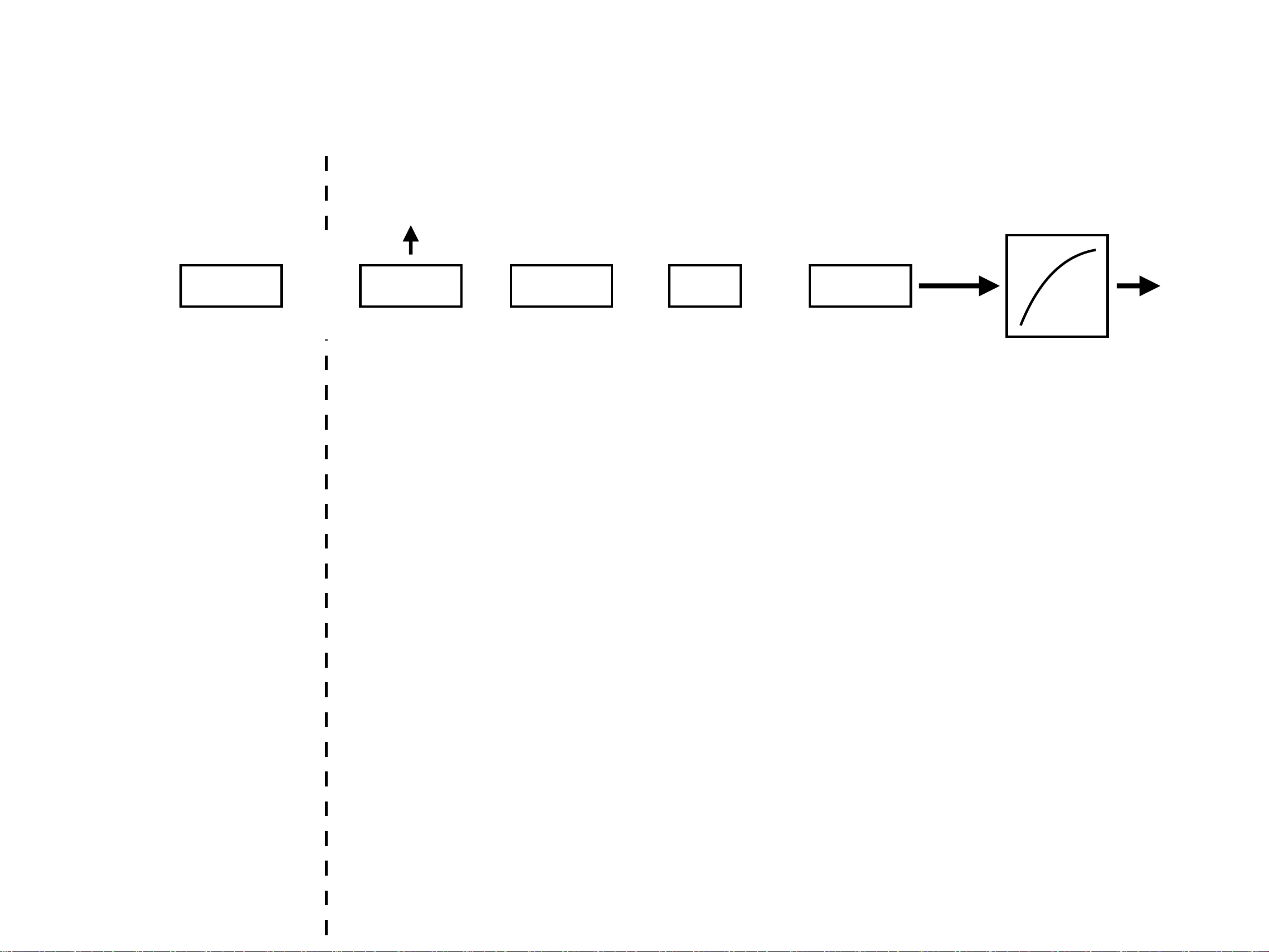
hVOL bVTR
X
=
80% 50% 40%
hVOL is “Host Volume”; a GLOBAL
volume which is always maintained
and stored in the SKAA transmitter.
hVOL is usually linked to the host
device volume (e.g. iOS, Mac OS,
Windows or Android system volume)
and mirrors it. If volume data from
the host device is not available (for
example from dumb audio sources
like a 3.5mm AUX input), then hVOL
is set to full up.
hVOL affects all receivers bonded to
this transmitter (up to 4 of them)
bVTR is “Bay
Volume Trim”
This is a LOCAL
volume which
is stored and
maintained in
the Receiver.
If this Receiver
is part of a
Cluster, bVTR
affects all
nodes in the
Cluster.
nVOL is transformed
through a volume table
(so a log curve may be
applied) prior to
sending the volume
commands to the
amplifier chip via I2C
I2C
volume
command
to Amp
nVOLbMUT
1
X
bMUT is “Local”
mute which is
stored and
maintained in
the Receiver.
3x clicking the
BOND BUTTON
will toggle
bMUT. It’s a 1
or 0.
nVOL is
continuously
being calculated
in the receiver.
It is the product
of all the
parameters on
the left.
speaker volume
indication (if any)
transmitter side receiver side
nVTR
100%
nVTR is “Node
Volume Trim”
which is
disabled (set to
full up) in most
products.
It is used only
in select cases,
such as for
trimming
volume in
subwoofers
which are slave
nodes in
Clusters.
If this Receiver
is part of a
Cluster, only
this receiver is
affected (all
other member
nodes of the
Cluster are not)
X
Notes
•
M-Link Global Volume (SKAA API hVOL) is
always fixed at “full up” (0xFF)
•
M-Link I2C volume scaling takes place in
the DAC chip
Malibu M-Link by Wet Sounds
How SKAA Volume Works
Eleven Engineering Inc.
063023
Chip:
Ginseng
ADC
DAC
CANBUS interface
ON Tx
√
√
-
√
VO
RF off
√
-
√
Forced VO
RF off
-
-
√
ON Rx
√
-
√
√
Standby
√
-
-
√
Sleep
RF 33% duty cycle
-
-
√
Chip Power
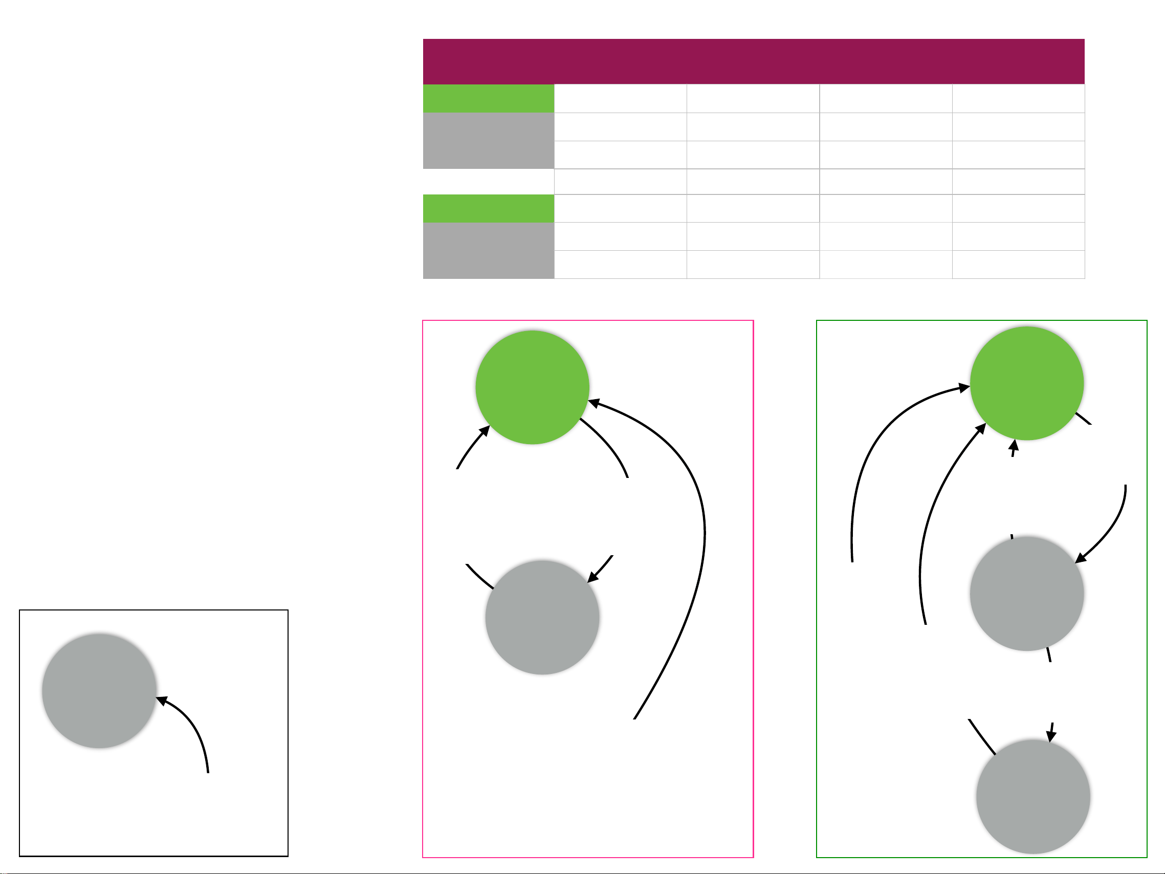
Malibu M-Link by Wet Sounds
Power States
Eleven Engineering Inc.
063023
Rx mode
60 min after
entering
Standby
Sleep
Notes
•
“VO” means Virtual Off —this is a power saving
state for SKAA transmitters, triggered by lack
of audio (silence).
•
In VO state, Ginseng’s RF section is shut off
causing all Bonds to drop (all Bonded SKAA
receivers are dropped)
•
“Standby” is a power saving state for SKAA
receivers.
•
in Standby state, Ginseng shuts off the ADC,
DAC and buffers
•
“Sleep” is a power saving state for SKAA
receivers. Sleep is triggered by a loss of Bond.
•
In Sleep state, the SKAA receiver improves on
the power saving performance of Standby state
by also duty cycling the SKAA radio. You can
tell the unit has gone to sleep when the SKAA
indicator shuts off and the Power LED dims
•
Powering off certain chips will be effected by
holding them in RESET
•
Power OFF commands sent from MFD to M-Link
will actually place the M-Link into VO or Sleep
state
Tx mode
VO
ON
Tx
2.5 min
after
Silence
Detected
Audio
Detected
or User
clicks any
button
Bond
Restored or
User clicks any
button
Bond
Restored
or User
clicks any
button
10 min
after loss
of Bond
ON
Rx
Standby
MFD User
selects
TRANSMIT
mode
MFD
User
selects
RECEIVE
mode
All modes
Forced
VO
MFD
User
selects
OFF