Model: TSP60/TSP72/TSP84
TSP60D/TSP72D/TSP84D


TABLE OF CONTENTS
TABLE OF CONTENTS 1
INTRODUCTION 2
OPERATOR RESPONSIBILITIES
9
PRE-OPERATION INSPECTION
9
START-UP AND FIELD OPERATION
9
OPERATING TIPS
9
MAINTENANCE SCHEDULE
11
LUBRICATION POINTS
11
HARDWARE RETENTION AND REPLACEMENT
11
HITCH ASSEMBLY
SPRING ARM KIT ASSEMBLY
3
5
5
6
DELIVERY CHECKLIST
TRACTOR REQUIREMENTS AND COMPATIBILITY
7
8
TRACTOR HOOK-UP
8
SAFETY ALERT SYMBOL AND SIGNAL WORDS
3
GENERAL SAFETY RULES
3
EQUIPMENT SAFETY GUIDELINES
4
OPERATIONAL SAFETY
4
MAINTENANCE SAFETY
4
SAFETY INFORMATION
ASSEMBLY INSTRUCTIONS
9
OPERATION
TRANSPORT
10
STORAGE
10
10
TRANSPORT AND STORAGE
11
MAINTENANCE AND LUBRICATION
12
TROUBLESHOOTING
12
TORQUE GUIDELINES
14
SOIL PULVERIZER PARTS ASSEMBLY
(TSP60, TSP72, TSP84)
15
PARTS LIST (TSP60, TSP72, TSP84)
16
SOIL PULVERIZER PARTS ASSEMBLY
(TSP60D, TSP72D, TSP84D)
17
PARTS LIST (TSP60D, TSP72D, TSP84D)
1
www.mechmaxx.com
TABLE OF CONTENTS

INTRODUCTION
2
www.mechmaxx.com
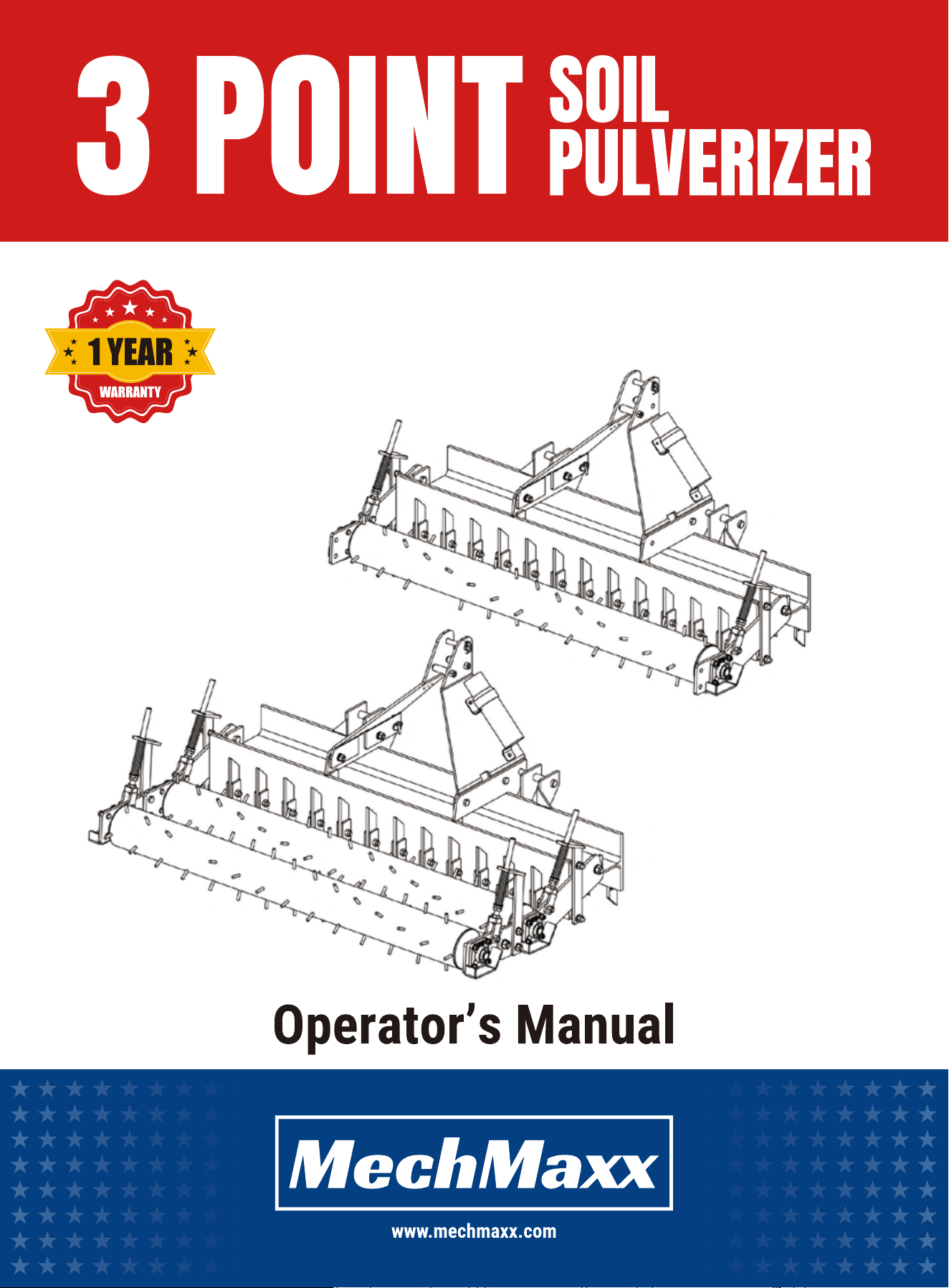
This manual provides safety, assembly, operation, adjustment, maintenance, and storage information for a 3-point hitch
soil pulverizer. Read and understand this manual before attempting to assemble, transport, operate, or service this imple-
ment. Keep this manual with the machine at all times.
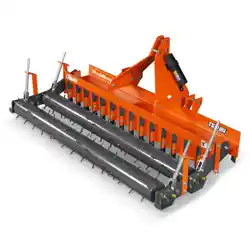
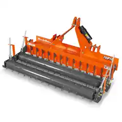
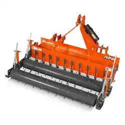
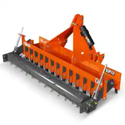
The 3 Point Soil Pulverizer is a ground-engaging implement designed to break soil clods, level and smooth cultivated
ground, and prepare seedbeds. The implement is equipped with front and rear rows of scarifier shanks and spring-loaded
roller assemblies to enhance soil penetration, maintain consistent ground contact, and absorb shock during operation.
Depending on the model, the pulverizer is configured with one or two rear spiked rollers to provide effective soil pulverizing
and finishing.
• Seedbed preparation after primary tillage
• Landscape leveling and topsoil finishing
• Breaking up soil clods and smoothing ruts
• Preparing ground for sod installation, seeding, and general lawn or field renovation
Common applications include:
• Ripping or removing concrete, asphalt, or blacktop
• Stump removal or contact with immovable objects
• Operating in rocky conditions where repeated heavy impacts are expected
• Deep subsoiling or primary tillage operations
Not recommended for:
INTRODUCTION
3
www.mechmaxx.com
SAFETY INFORMATION
SAFETY INFORMATION
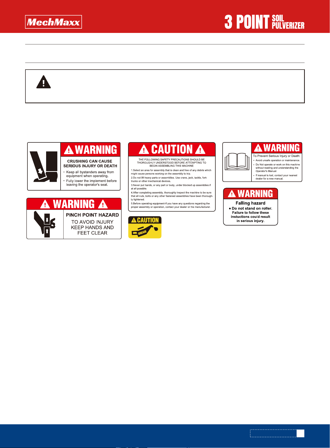
A safety alert symbol is used to identify safety messages. When you see a safety message, be alert to the possibility of
injury. Follow recommended precautions and safe operating practices.
1. Select an area for assembly that is clean and free of any debris which might cause persons working on the assembly
to trip.
2. Do not lift heavy parts or assemblies. Use crane, jack, tackle, fork trucks, or other mechanical devices.
3. Preview the assembly instructions in your operator’s manual before proceeding further.
4. If the assembly instructions call for parts or assemblies to be blocked up, use only blocking material that is in good
condition and is capable of handling the weight of the assembly to be blocked. Also ensure that the blocking material is
on a clean, dry surface.
5. Never put hands, or any part of the body, under blocked-up assemblies if at all possible.
6. After completing assembly, thoroughly inspect the machine to be sure that all nuts, bolts, hydraulic fittings, or any
other fastened assemblies have been thoroughly tightened.
7. Before operating the machine, thoroughly read the operation section of your operator’s manual.
8. Before operating, read the machine section of your operator’s manual to be sure that any parts requiring lubrication,
such as bearings or other lubricated components, are properly lubricated to avoid any possible damage.
9. Before operating the equipment — if you have any questions regarding the proper assembly or operation, contact your
dealer or representative.
SAFETY ALERT SYMBOL AND SIGNAL WORDS
GENERAL SAFETY RULES
THE FOLLOWING SAFETY PRECAUTIONS SHOULD BE THOROUGHLY UNDERSTOOD BEFORE ATTEMPTING
TO BEGIN ASSEMBLING THIS MACHINE
CAUTION

4
www.mechmaxx.com
SAFETY INFORMATION
1. Never use alcoholic beverages or drugs which can hinder alertness or coordination while operating this equipment.
Consult your doctor about operating this machine while taking prescription medications.
2. Review the safety instructions with all users annually.
3. This equipment is dangerous to children and persons unfamiliar with its operation. The operator should be a responsible
adult familiar with your machinery and trained in this equipment’s operations. Do not allow persons to operate or assem-
ble this unit until they have read this manual and have developed a thorough understanding of the safety precautions and
of how it works.
4. Never exceed the limits of a piece of machinery.
5. Do not modify the equipment in any way. Unauthorized modification may impair the function and could affect the life of
the equipment.
EQUIPMENT SAFETY GUIDELINES
1. The use of this equipment is subject to certain hazards which cannot be protected against by mechanical means or
product design. All operators of this equipment must read and understand this entire manual, paying particular attention
to the operating procedures prior to use. If there is something in this manual you do not understand, ask your supervisor
or your dealer to explain it to you.
2. Personal protection equipment, including hard hat, safety glasses, safety shoes, and gloves, is recommended during
assembly.
3. Never permit any person to ride or board the implement at any time.
4. A heavy load can cause instability in driving a tractor. Make sure the front or rear of the tractor is properly counter-bal-
anced with weights. Always drive slowly — especially around turns. An unstable tractor could steer badly and possibly tip
over, causing injury or death.
5. Most accidents occur because of neglect or carelessness. Keep all helpers and bystanders at a safe distance.
6. Do not operate close to ditches or creeks. Slow down when operating over rough ground.
7. When adjusting the position or angle of the implement, be sure that your feet are never under the implement.
8. Be careful to avoid catching the implement on stumps or other immovable objects.
OPERATIONAL SAFETY
1. Keep all persons away from the operator control area while performing service, or maintenance.
2. Periodically tighten all bolts, nuts, and screws and check that all cotter pins are properly installed to ensure the unit
is in a safe condition.
3. Never use your hands to locate a hydraulic leak on attachments. Use a small piece of cardboard or wood.
4. Never replace hex bolts with less than grade five bolts unless otherwise specified. Refer to the bolt torque chart for
head identification markings.
MAINTENANCE SAFETY
ALWAYS OBEY ALL SAFETY RULES!
ALWAYS BE CAREFUL!
5
www.mechmaxx.com
1. Remove the left and right hitch plates from the crate.
2. Position the hitch plates on the main frame and secure them using the provided bolts and nuts.
Note: The bolts used to attach the hitch plates to the main frame are shipped pre-installed in the corresponding
holes of the main frame.
3. Install all supplied hitch pins onto the implement.
4. Install the manual canister.
5. Tighten all hardware to the specified torque values.
ASSEMBLY
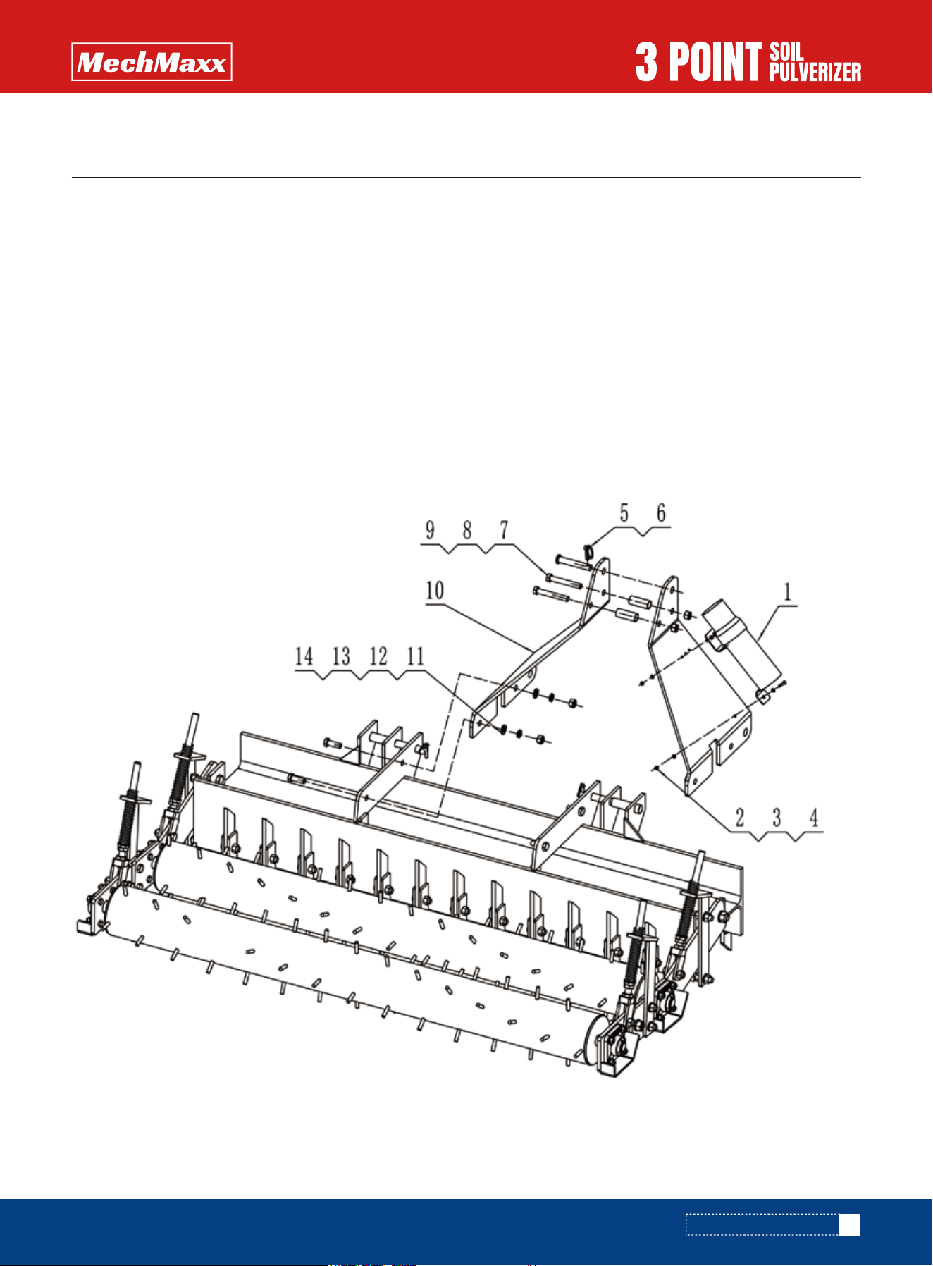
FIG. 1
1. Hitch Assembly (Refer to Figure 1)
Assembly procedures vary by model. If assembly is required, use appropriate lifting equipment and follow safe handling
practices. Loosely assemble components first, align parts, and then tighten hardware to final torque.
ASSEMBLY INSTRUCTIONS
ASSEMBLY INSTRUCTIONS

6
www.mechmaxx.com
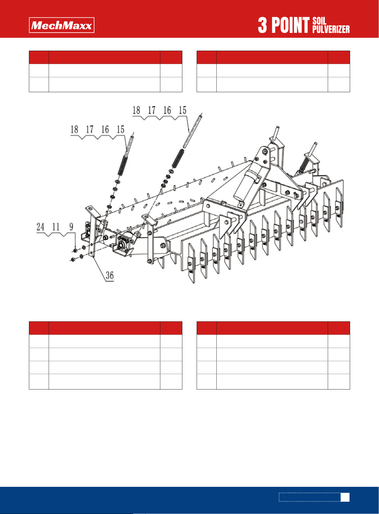
1. Remove all spring arm kit components from the crate.
2. For one-roller models (Refer to Figure 2), attach the spring guide rod assemblies to the roller limit rod bracket.
For two-roller models (Refer to Figure 3), loosely attach the roller limit rod bracket to the primary roller assembly and the
connecting plate using the supplied bolts, flat washers and nuts. Then attach the spring guide rod assemblies to the
roller limit rod bracket.
Note: The bolts used to attach the spring arm kit are shipped pre-installed in the corresponding holes of the kit.
3. Tighten all hardware to the specified torque values.
2. Spring Arm Kit Assembly (Refer to Figure 2)
1
4
8
4
1
1
2
No. DESCRIPTION Qty
1
2
3
4
5
6
7
Manual canister
Bolt M6*25
Flat washer φ6
Lock Nut M6
Pinφ19
O Pin
Bolt M16*110
2
2
2
4
4
4
4
No. DESCRIPTION Qty
8
9
10
11
12
13
14
Spacer1
Lock Nut M16
Top Link Bar
Flat washer φ16
Spring washer φ16
Nut M16
Bolt M16*45
ASSEMBLY INSTRUCTIONS
FIG. 2
7
www.mechmaxx.com
Use the following checklist prior to delivery or prior to first use:
• All components are included.
• Grease fittings checked and lubricated as needed.
• Safety guards in place.
• All hardware tight.
• Bolts torqued correctly.
• Attached unit to tractor.
• Field adjusted.
• Test run.
DELIVERY CHECKLIST
4
4
4
4
No. DESCRIPTION Qty
9
11
15
16
Lock Nut M16
Flat washer φ16
Bolt M20
Spring
4
12
4
1 / 1
No. DESCRIPTION Qty
17
18
24
36
Flat washer φ20
Nut M20
Bolt M16*50
Limited Rod L / Limited Rod R
2
2
No. DESCRIPTION Qty
15
16
Bolt M20
Spring
4
2
No. DESCRIPTION Qty
17
18
Flat washer φ20
Nut M20
ASSEMBLY INSTRUCTIONS
FIG. 3

8
www.mechmaxx.com
Ensure the tractor and implement are properly matched before use.
• 3-point hitch category must match the implement (Category 1 or Category 2).
• Tractor horsepower must be within the implement’s rating.
• Tractor must be adequately ballasted to maintain steering control and stability.
• Tire track width and 3-point geometry must provide clearance for turns and transport.
• Use ROPS and seat belt as recommended by tractor manufacturer.
TRACTOR REQUIREMENTS AND COMPATIBILITY
Follow this sequence for safe and correct attachment:
• Back tractor to implement and align lower lift arms with hitch points.
• Set parking brake, shut off engine, remove key, and dismount.
• Attach lower lift arms using correct hitch pins; secure with retaining clips/lynch pins.
• Attach the top link to the implement A-frame/top mast using the top hitch pin; secure with retaining clip.
• Adjust sway/limit chains or stabilizers to reduce side-to-side movement.
• Slowly raise the implement a few inches and check for interference with tires, drawbar, or PTO shield (as applicable).
• Level implement side-to-side using the tractor’s leveling box/turnbuckle.
• Adjust top link to set desired implement pitch (front-to-rear level or slightly nose-down per field conditions).
TRACTOR HOOK-UP
ASSEMBLY INSTRUCTIONS

9
www.mechmaxx.com
The operator must be trained and competent to operate the tractor and implement. Keep all bystanders at a safe
distance. Never allow riders on the tractor or implement.
OPERATOR RESPONSIBILITIES
Before each use, perform a complete inspection and service check to ensure the tractor and soil pulverizer are in safe
working condition. Do not operate if any condition affecting safe operation is found.
Pulverizer inspection items
• Operator’s manual stored in the canister and secured
• All safety decals present and legible
• Hitch pins properly installed and retained
• No cracks in hitch and frame; weldments intact
• All frame bolts in place and tightened to specification
• Bearings lubricated and retained
• Rollers/spikes clear of mud, vegetation, and debris
• Roller attachment bolts in place and tight
• Scarifier shanks properly retained; points in good condition
PRE-OPERATION INSPECTION
Recommended operating sequence:
• Clear the area of obstacles and foreign objects before starting work.
• Lower the implement slowly to the ground before beginning forward motion.
• Begin at a low ground speed; increase speed only as conditions allow and the desired finish is achieved.
• Use straight passes with slight overlap to avoid ridges.
• Avoid sharp turns while the implement is fully engaged in the soil; lift slightly before turning.
START-UP AND FIELD OPERATION
• Dry, friable soil will produce a finer finish; overly wet soil may clod and stick to rollers.
• Multiple light passes are generally preferable to one aggressive pass in compacted soil.
• If equipped with scarifiers, begin with a shallow setting and increase depth gradually.
• If rollers bounce or fail to stay on the ground, adjust spring tension (where equipped).
OPERATING TIPS
OPERATION
OPERATION

Follow these guidelines when transporting the tractor and implement:
• Raise the implement to a safe transport height and ensure adequate ground clearance.
• Reduce speed and use extra caution on turns, slopes, and rough ground.
• Do not allow anyone to ride on the implement.
• Comply with all federal, state, and local roadway requirements; use lighting and marking as required.
TRANSPORT
• Clean the implement thoroughly and remove mud, vegetation, and debris.
• Inspect for worn or damaged parts and repair before storage.
• Lubricate all grease points prior to storage.
• Lower the implement to the ground on a firm, level surface; block securely if needed.
• Protect exposed metal surfaces with rust preventive if stored outdoors or for extended periods.
• Store away from human activity and keep children away from the stored implement.
STORAGE
10
www.mechmaxx.com
TRANSPORT AND STORAGE
TRANSPORT AND STORAGE
Before each use:
• Inspect for loose fasteners, cracked welds, and missing hardware.
• Inspect rollers/spikes for damage and debris buildup; clean as needed.
• Inspect shanks and points for wear; replace as a set when practical to maintain uniform height.
After first 10 hours of use and every 10 hours thereafter:
• Lubricate roller bearings (both ends) with multi-purpose grease (as required).
• Re-check fastener tightness and re-torque critical hardware.
MAINTENANCE SCHEDULE (MINIMUM RECOMMENDATIONS)
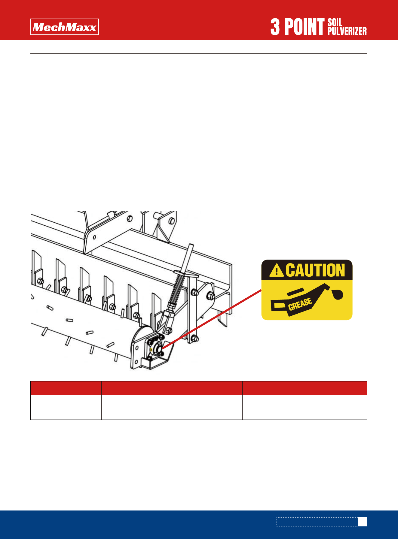
Lubricate all grease fittings at recommended intervals. Use a high-quality multi-purpose grease compatible with your
operating environment.
LUBRICATION POINTS
Periodically tighten all bolts, nuts, and screws. Replace damaged fasteners with equivalent grade hardware. Use new
cotter pins/retainers after removal.
HARDWARE RETENTION AND REPLACEMENT
11
www.mechmaxx.com
MAINTENANCE AND LUBRICATION
MAINTENANCE AND LUBRICATION
Location Interval Lubricant Quantity Notes
Rear roller
bearing (each end)
10 hours Multi-purpose
grease
As required Wipe fitting
clean before greasing

12
www.mechmaxx.com
Use the table below to diagnose common operating issues.
Problem Likely Cause Corrective Action
Roller(s) bouncing or not staying
on ground
Spring tension too low; ground speed
too high; insufficient frame weight
Increase spring tension (if equipped),
reduce speed, and add ballast as
recommended by the tractor manufacturer
if applicable.
Shanks bending sideways Turning while shanks engaged;
striking obstacles
Lift shanks out of ground while turning;
clear obstacles; reduce speed.
Scarifier shanks do not engage
the soil adequately
3-point not fully lowered; soil too
hard/dry; insufficient weight
Lower 3-point fully; make multiple
shallow passes; add ballast as
recommended by the tractor
manufacturer; adjust pitch.
Frame or shanks bending Contact with immovable objects;
using implement for prohibited tasks
Avoid rocks/stumps; do not rip
concrete/asphalt; operate within rated
limits.
Uneven finish (ridges/low spots) Implement not level; overlap
inconsistent
Level implement side-to-side and
front-to-rear; maintain consistent overlap.
Excessive vibration/noise from
roller area
Bearing dry/damaged; debris
wrapped on roller
Clean roller; lubricate bearings; replace
bearings if noise persists.
TROUBLESHOOTING
The tables shown below give the correct torque values for various bolts and cap screws. Tighten all bolts to the torques
specified unless otherwise noted. Check tightness of bolts periodically, using bolt torque chart as a guide. Replace
hardware with the same length and grade of bolt.
TORQUE GUIDELINES
TROUBLESHOOTING

13
www.mechmaxx.com
Torque figures indicated above are valid for non-greased or non-oiled threads and heads otherwise specified. Therefore, do
not grease or oil bolts or cap screws unless otherwise specified in this manual. When using locking elements, increase
torque values by 5%
Torque tolerance +0%,-15% of torquing values. Unless otherwise specified use torque values listed above.
1
in-tpi = nominal thread diameter in inches-threads per
inch
2
N.m= newton-meters
3
ft-lb= foot pounds
4
mm x pitch = nominal thread diameter in millimeters x
thread pitch
TORQUE VALUES CHART FOR COMMON BOLT SIZES
TORQUE VALUES CHART FOR COMMON BOLT SIZES
Grade 2 Grade 5
Bolt Head Identification Bolt Head Identification
Grade 8 Class 5.8 Class 8.8 Class 10.9
Bolt Size
(Inches)
in-tpi
1
Bolt Size
(Inches)
mm x pitch
4
N.m
2
ft-lb
3
ft-lb
N.m
ft-lb
N.m
ft-lb
N.m
ft-lb
N.m
ft-lb
1/4"-20
1/4"-28
5/16"-18
5/16"-24
3/8" -16
3/8" -24
7/16" -14
7/16"-20
1/2" -13
1/2" -20
9/16"-12
9/16"-18
5/8" - 11
5/8" -18
3/4" -10
3/4" -16
7/8" -9
7/8" -14
1"-8
1"-12
1-1/8"-7
1-1/8" -12
1-1/4"-7
1-1/4" -12
1-3/8"-6
1-3/8" -12
1-1/2" -6
1-1/2" -12
M5X0.8
M6X1
M8X 1.25
M8X1
M10X 1.5
M10X0.75
M12X 1.75
M12X 1.5
M12X1
M14 X2
M14 X 1.5
M16X2
M16X 1.5
M18 X 2.5
M18 X 1.5
M20 X 2.5
M20 X 1.5
M24X3
M24 X2
M30 X 3.5
M30×2
M36 X3.5
M36X2
4
7
17
18
33
39
58
60
90
92
99
145
155
195
220
280
310
480
525
960
1060
1730
1880
3
5
12
13
25
29
42
44
66
68
73
105
115
145
165
205
230
355
390
705
785
1270
1380
6
11
26
28
52
61
91
95
105
145
155
225
240
310
350
440
650
760
830
1510
1680
2650
2960
5
8
19
21
39
45
67
70
77
105
115
165
180
230
260
325
480
560
610
1120
1240
1950
2190
9
15
36
39
72
85
125
130
145
200
215
315
335
405
485
610
900
1050
1150
2100
2320
3660
4100
7
11
27
29
53
62
93
97
105
150
160
230
245
300
355
450
665
780
845
1550
1710
2700
3220
7.4
8.5
15
17
27
31
43
49
66
75
95
105
130
150
235
260
225
250
340
370
480
540
680
750
890
1010
1180
1330
5.6
6
11
13
20
22
32
36
49
55
70
79
97
110
170
190
165
185
250
275
355
395
500
555
655
745
870
980
11
13
24
26
42
47
67
75
105
115
150
165
205
230
360
405
585
640
875
955
1080
1210
1520
1680
1990
2270
2640
2970
8
10
17
19
31
35
49
55
76
85
110
120
150
170
265
295
430
475
645
705
795
890
1120
1240
1470
1670
1950
2190
16
18
33
37
59
67
95
105
145
165
210
235
285
325
510
570
820
905
1230
1350
1750
1960
2460
2730
3230
3680
4290
4820
12
14
25
27
44
49
70
78
105
120
155
170
210
240
375
420
605
670
910
995
1290
1440
1820
2010
2380
2710
3160
3560
8.85.8 10.9
14
www.mechmaxx.com
SOIL PULVERIZER PARTS ASSEMBLY (TSP60, TSP72, TSP84)
SOIL PULVERIZER PARTS ASSEMBLY (TSP60, TSP72, TSP84)
15
www.mechmaxx.com
PARTS LIST (TSP60, TSP72, TSP84)
PARTS LIST (TSP60, TSP72, TSP84)
1
4
8
4
1
3
2
2
29/33/37
2
8
4
12
4
2
2
4
2
1
1
2
2
2
21/25/29
21/25/29
1
1
1
2
No. DESCRIPTION Qty
1
2
3
4
5
6
7
8
9
10
11
12
13
14
15
16
17
18
19
20
21
22
23
24
25
26
27
28
29
Manual Canister
Bolt M6*25
Flat washer φ6
Lock Nut M6
Pinφ19
O Pin
Bolt M16*110
Spacer1
Lock Nut M16
Top Link Bar
Flat washer φ16
Spring washer φ16
Nut M16
Bolt M16*45
Bolt M20
Spring
Flat washer φ20
Nut M20
Limited Rod R
Side Plate R
U Nut
Bolt M16*60
Pinφ22
Bolt M16*50
Shank
Frame
Side Plate L
Limited Rod L
Bolt M20*50
2
2
8
8
8
1
No. DESCRIPTION Qty
30
31
32
33
34
35
Lock Nut M20
UCF206
Bolt M12*45
Flat washer φ12
Lock Nut M12
Roller
16
www.mechmaxx.com
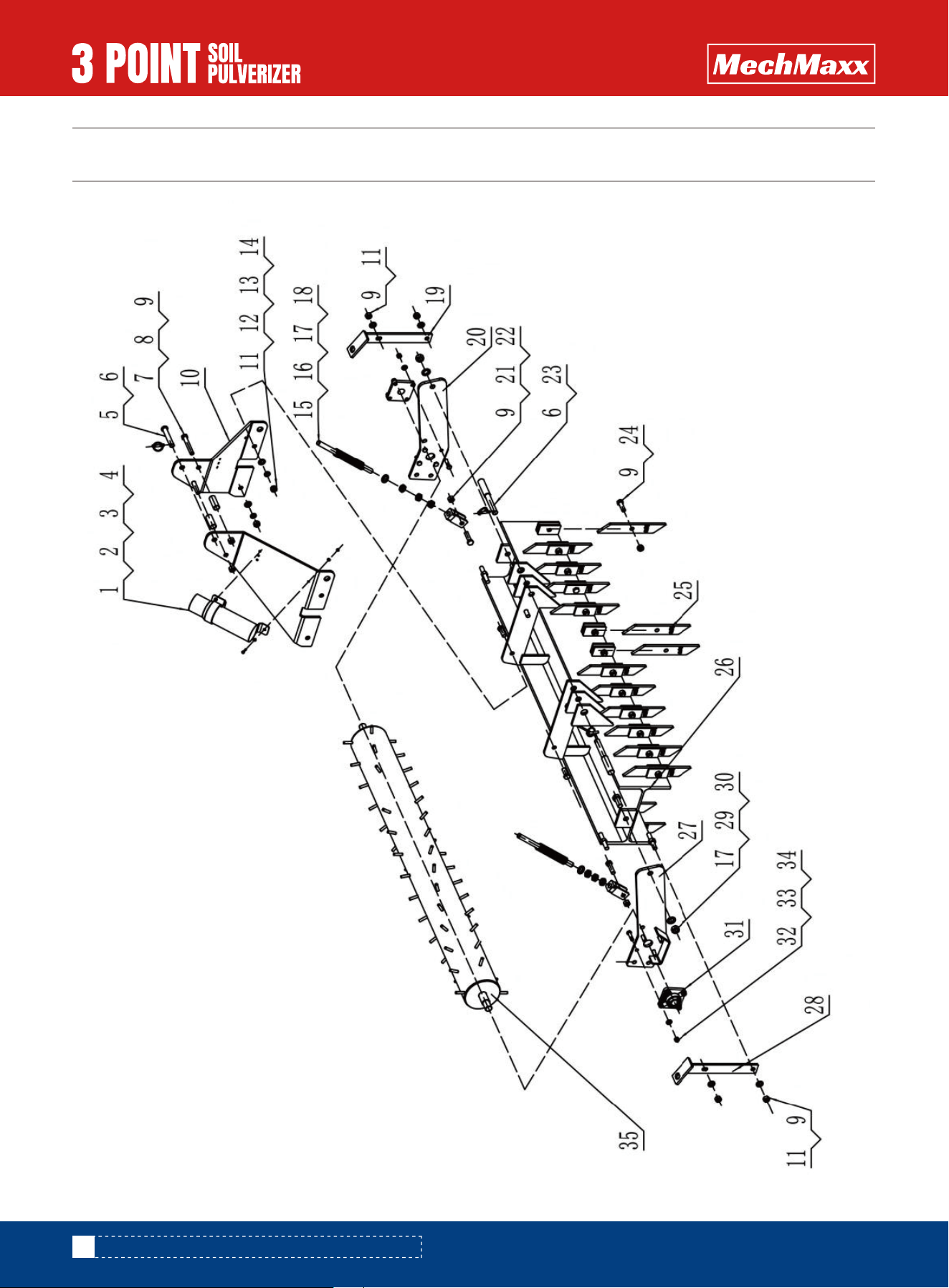
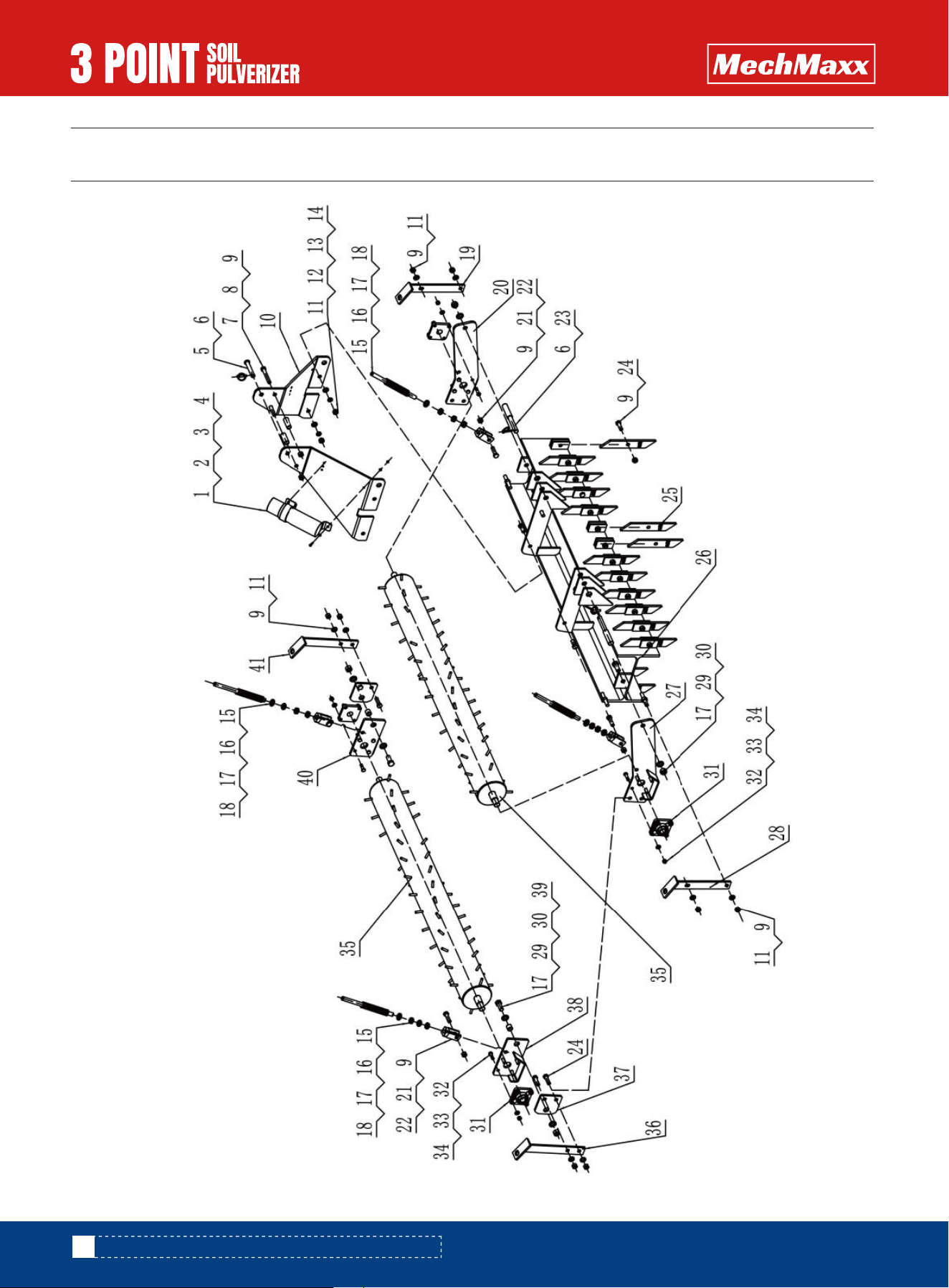
SOIL PULVERIZER PARTS ASSEMBLY (TSP60D, TSP72D, TSP84D)
SOIL PULVERIZER PARTS ASSEMBLY (TSP60D, TSP72D, TSP84D)

17
www.mechmaxx.com
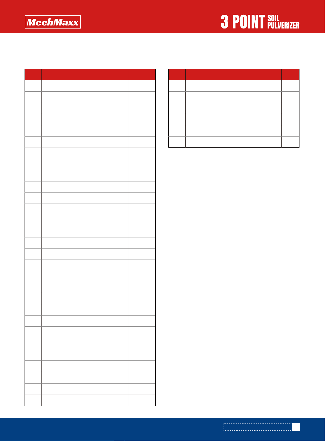
PARTS LIST (TSP60D, TSP72D, TSP84D)
PARTS LIST (TSP60D, TSP72D, TSP84D)
1
4
8
4
1
3
2
2
35/39/43
2
12
4
12
4
4
4
10
12
1
1
4
4
2
25/29/33
21/25/29
1
1
1
4
No. DESCRIPTION Qty
1
2
3
4
5
6
7
8
9
10
11
12
13
14
15
16
17
18
19
20
21
22
23
24
25
26
27
28
29
Manual Canister
Bolt M6*25
Flat washer φ6
Lock Nut M6
Pinφ19
O Pin
Bolt M16*110
Spacer1
Lock Nut M16
Top Link Bar
Flat washer φ16
Spring washer φ16
Nut M16
Bolt M16*45
Bolt M20
Spring
Flat washer φ20
Nut M20
Limited Rod R
Side Plate R
U Nut
Bolt M16*60
Pinφ22
Bolt M16*50
Shank
Frame
Side Plate L
Limited Rod L
Bolt M20*50
4
4
16
16
16
2
1
2
1
2
1
1
No. DESCRIPTION Qty
30
31
32
33
34
35
36
37
38
39
40
41
Lock Nut M20
UCF206
Bolt M12*45
Flat washer φ12
Lock Nut M12
Roller
Limited Rod L
Connection
Side Plate L
Spacer2
Side Plate R
Limited Rod R