1
MIA-3DSTc4u
Installation Guide
2026.06 R02
METAIAM
3
Safety Instructions
⚫
Before connecting the power supply, refer to the installation manual.
⚫
Do not insert any objects into the product’s openings. This may damage the internal circuitry and
result in fire or electric shock.
⚫
Avoid spilling liquids onto the product.
⚫
During thunderstorms or if the product is not used for an extended period, disconnect the power
supply to protect the product from damage caused by power surges.
⚫
Do not overload the power socket or power cables, as this may cause fire or electric shock.
⚫
Do not open the product to avoid the risk of electric shock. For safety reasons, only professional
service personnel should open the product.
⚫
Place the product in a secure location, as drops or falls may cause damage.
⚫
Disconnect the product from the power supply before cleaning, and do not use aerosol cleaners.
⚫
The product should be inspected by professional service personnel if any of the following occurs:
•
The power cord or plug is damaged.
•
Liquid has entered the product.
•
The product has been exposed to a humid environment.
•
The product has been dropped or damaged.
•
The product shows visible signs of damage.
•
The product is not functioning properly or cannot be operated according to the manual.
⚫
Before installation, please carefully inspect the entire unit and its components. If any abnormalities
are found, contact the sales representative and return the damaged product. All power connectors
must be properly connected to the power supply.
⚫
Use only the power supply provided with the product.
⚫
If unusual smells, sounds, or smoke are detected, immediately unplug the power and contact the
sales representative. Under no circumstances should you hit or drop the product.
⚫
Make sure all cables are connected correctly and securely.
⚫
The power socket should be installed near the device and should be easily accessible
⚫
【低功率射頻器材設備警語 (LP0002 3.8.2)_2020.07.01 】
取得審驗證明之低功率射頻器材,非經核准,公司、商號或使用者均不得擅自變更頻率、加大功率或變更原設
計之特性及功能。低功率射頻器材之使用不得影響飛航安全及干擾合法通信;經發現有干擾現象時,應立即停
用,並改善至無干擾時方得繼續使用。前述合法通信,指依電信管理法規定作業之無線電通信。低功率射頻器
材須忍受合法通信或工業、科學及醫療用電波輻射性電機設備之干擾。
15.21
Caution!
Any changes or modifications not expressly approved by the party responsible for compliance
could void the user's authority to operate the equipment.
15.19
This device complies with Part 15 of the FCC Rules. Operation is subject to the following two
conditions:
(1) this device may not cause harmful interference, and
(2) this device must accept any interference received, including interference that may cause
undesired operation.
2
3
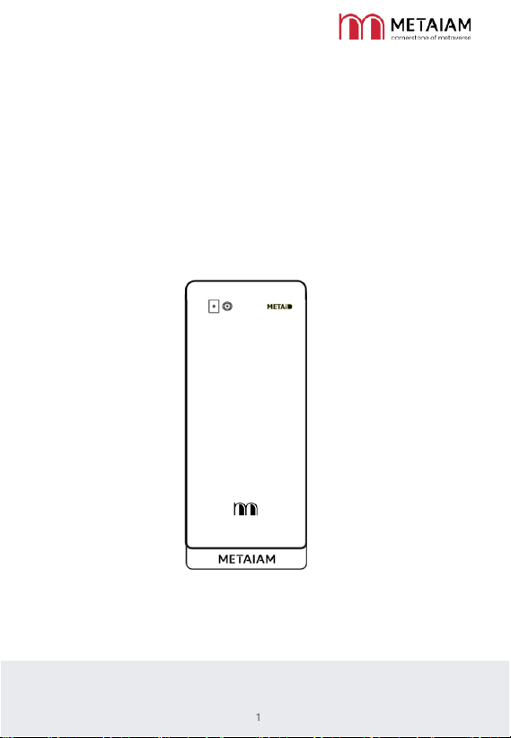
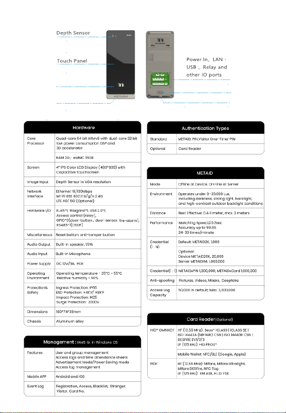
1. Product Appearance
2. Product Specification
Card Reader (Optional)
Microphone
Restart Button
Speaker
4
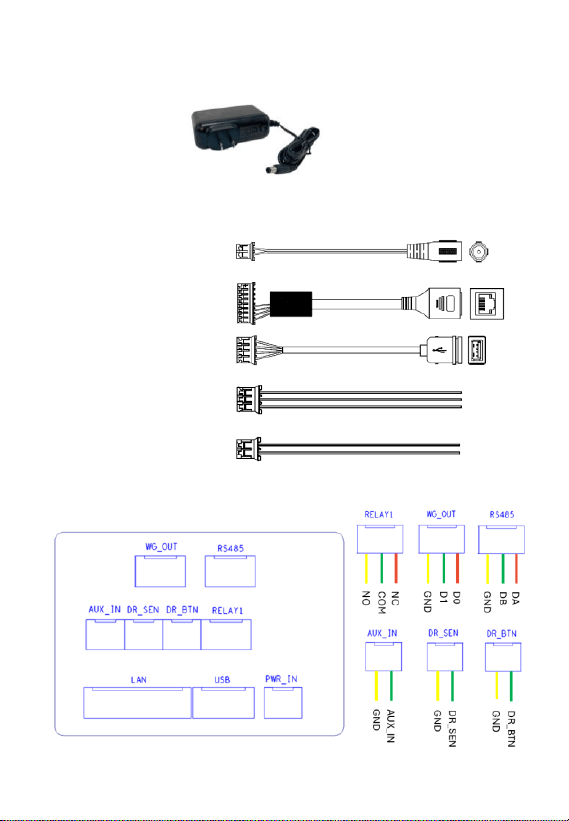
3. Power Adapter
The adapter is shown in the diagram below. The power input can support
100V~240V and 50/60Hz, and the output is 12V/3A.
4. Instructions for Connecting the Cable and Rear Panel Connector
4-1 DC Jack Cable :
4-2 LAN Cable :
4-3 USB Cable :
4-4 3-Pin IO Cable :
4-5 2-Pin IO Cable:
5. Product Installation
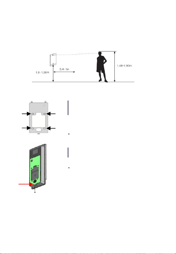
Before installation, the mounting height of the main unit must be determined. For MIA-3DSTc4u
series models, it is recommended that the bottom of the device be positioned 1.3 to 1.35 meters
above the ground. This allows for the recognition of individuals with heights ranging from 1.48 to
1.90 meters. The optimal measurement distance is 0.4 to 1 meter, as illustrated in the diagram below:
When the main unit is installed on a wall with an 86-
type mounting box, the mounting plate can be directly
secured to the box using flat-head screws. If there is no
mounting box inside the wall, use a drill to make holes,
install expansion screw tubes, and then secure the
mounting plate with screws.
Refer to the diagram on the left for guidance.
Have the main unit on the wall-mounted bracket, then
secure it by tightening the screws at the bottom to
complete the installation. Refer to the diagram on the
left for guidance.
6. Operation Environment
Please use your product according to the following basic environmental requirements:
⚫ Operating temperature: -10 to 55°C (optional low-temperature operation from -35 to -10°C)
⚫ Operating humidity: 10% to 90% RH, non-condensing
⚫ Storage temperature: -10 to 60°C
Securing the main
unit
5
Diagram of the main unit installation height
Installing the wall-mounted bracket
7. Access Control Signal Connection Diagram
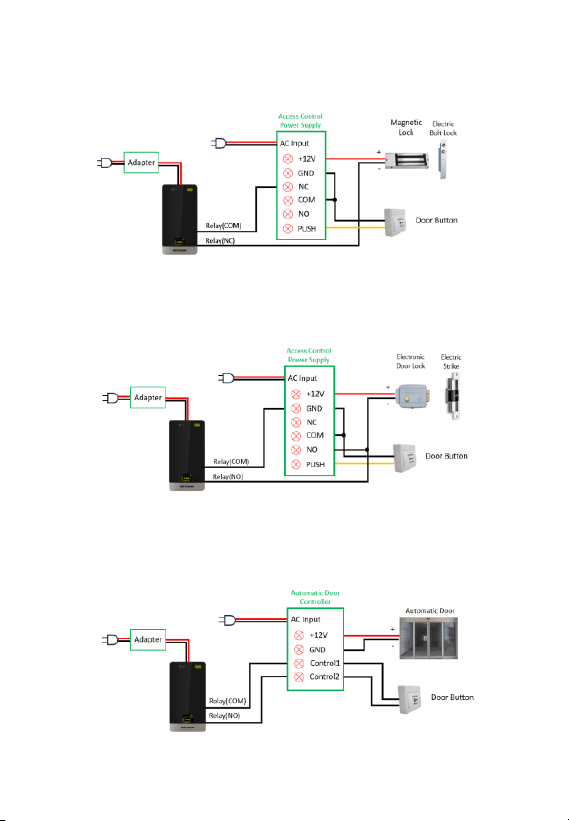
7-1 Connection between MIA-3DSTc4u and Lock
A. Fail Safe Lock - Magnetic Lock、Electric Bolt Lock
The negative pole (-) of the door lock is connected in series to the MIA-3DSTc4u device. When the
device's relay is triggered or the Door Button is pressed, the negative pole (-) of the door lock is
disconnected for cutting off power to the lock and thereby unlocking the door.
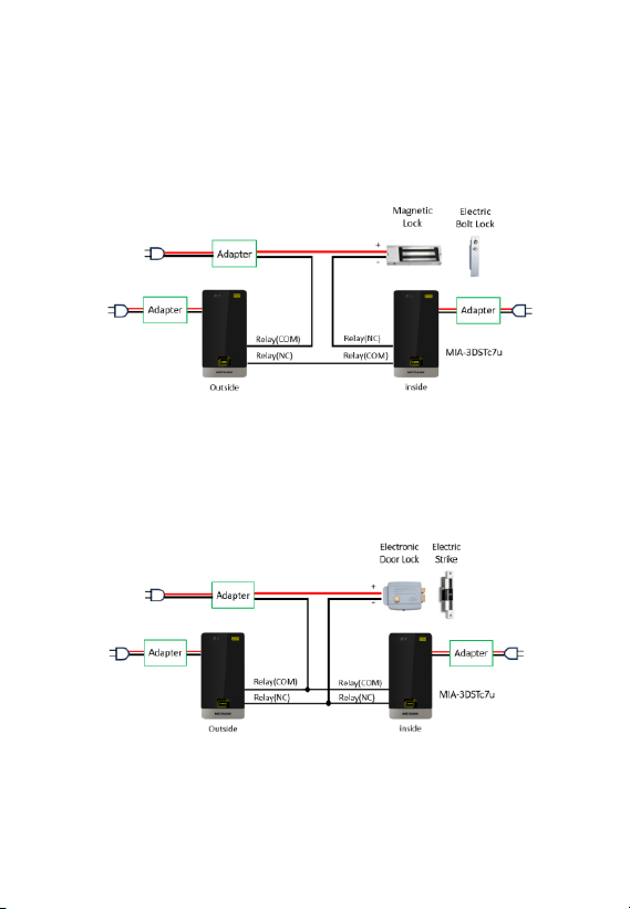
B. Fail Secure Lock – Electric Strike、Electronic Door Lock
The negative pole (-) of the door lock is connected in parallel to the MIA-3DSTc4u device. When the
device's relay is triggered or the Door Button is pressed, the negative pole (-) of the door lock is
connected for supplying power to the lock and unlocking the door.
C. Automatic Door
Both MIA-3DSTc4u device and Door Button are connected to the Access Door Controller. When the
device's relay is triggered or the Door Button is pressed, it triggers the Automatic Door Controller to
unlock the door.
6
MIA-3DSTc4u
MIA-3DSTc4u
MIA-3DSTc4u
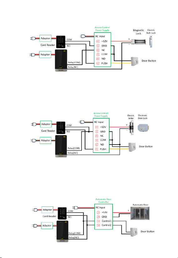
7-2 Connection for MIA-3DSTc4u and Card Reader
A. Fail Safe Lock - Magnetic Lock、Electric Bolt Lock
The negative terminal (-) of the door lock is connected in series to the MIA-3DSTc4u device (NC) and
the Access Control Power Supply. The card reader and Door Button are connected to Access Control
Power Supply. When the device's relay is triggered, or the card is successfully swiped, or Door Button is
pressed, the negative terminal (-) of the door lock will be disconnected and the door will be open.
B. Fail Secure Lock – Electric Strike、Electronic Door Lock
The negative terminal (-) of the door lock is connected in series to the MIA-3DSTc4u device (NO) and
the Access Control Power Supply. The card reader and Door Button are connected to Access Control
Power Supply. When the device's relay is triggered, or the card is successfully swiped, or Door Button is
pressed, the negative terminal (-) of the door lock will be disconnected and the door will be open.
C. Automatic Door
D.
7
MIA-3DSTc4u
MIA-3DSTc4u
MIA-3DSTc4u
The MIA-3DSTc4u device, card reader, and Door Button are all connected to the control signal lines of the
Automatic Door Controller. When the device's relay is triggered or the Door Button is pressed, the two
control signal lines of the Automatic Door Controller will be connected, and then the motor of automatic
door will be driven to open the door.
7-3 Dual devices outside and inside the door
A. Fail Safe Lock - Magnetic Lock、Electric Bolt Lock
The negative terminal (-) of the door lock is connected in series with two MIA-3DSTc4u devices. When
either device activates the relay, the negative terminal (-) of the door lock will be disconnected and the
door will be open.
B. Fail Secure Lock – Electric Strike、Electronic Door Lock
The negative terminal (-) of the door lock is connected in parallel with two MIA-3DSTc4u devices. When
either device activates the relay, the negative terminal (-) of the door lock will be disconnected and the
door will be open.
8
MIA-3DSTc4u
MIA-3DSTc4u
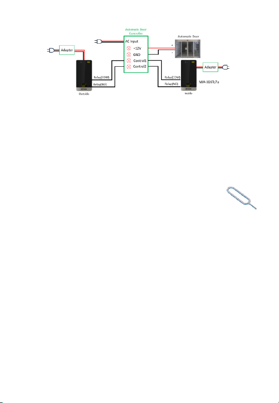
C. Automatic Door
Both MIA-3DSTc4u devices are connected to the control signal lines of the Automatic Door Controller.
When the device's relay is triggered, the two control signal lines of the Automatic Door Controller will be
connected, and then the motor of automatic door will be driven to open the door.
8. Operation Guidelines
Do not turn off the device during startup. Wait until the identity recognition interface appears and
the ‘Loading...’ message disappears before powering off.
Once the device is turned on, the identity recognition interface will display “Loading...". Please wait
for this message to disappear before performing any recognition tasks or settings.
9. Hardware Reboot (via Pin Tool)
⚫ Use the restart button on the main unit to perform a hardware reboot.
This should be done while the device is powered on.
⚫ Use the pin tool provided with the product to perform a hardware reboot. To reboot the device,
insert the pin tool into the reset hole, press and release it, the device will restart.
10. Common Recognition Issues and Solutions
⚫
Duplicate ID detected
⚫
Failure to follow modeling requirements
⚫
Significant difference between the model and the real person
⚫
There is a significant difference between the hairstyle during recognition and the hairstyle at
the time of facial model registration
To resolve these issues, delete the existing METAiD model and re-register the user’s METAiD.
11. Administrator Password Setup
It is strongly recommended to set an administrator password immediately after completing the
installation and configuration to make sure only the administrator can change the configuration. After
entering the access control settings page, click on "Admin Password", enter a 6-digit password, and
then click "SAVE". The system will return to the access control settings page and display a success
message.
Note: If the administrator password is lost and the settings page cannot be accessed, the
administrator password can only be changed through the management system.
Pin Tool :
9
MIA-3DSTc4u