Gas
Range
PRG Model User Manual
HausPRO

1001-082525-03 PRG Model USER MANUAL
Table of Contents
Safety Information
Before installing your range, read the entire instruction
manual. Installers, leave this manual with the homeowner.
WARNING: Suitable for use in household cooking area
ONLY. To reduce the risk of fire, electrical shock, or injury,
observe the following:
1. Use this range O NLY in the manner intended by the
manufacturer. If you have the questions, contact Hauslane
at 1-800-929-0168 or email at info@hauslane.com.
2. Before servicing or cleaning, switch power o at service
panel and lock service panel to prevent power from being
switched on accidentally. When the service disconnecting
means cannot be locked, securely fasten a prominent
warning device, such as a tag, to the service panel.
3. Installation work and electrical wiring MUST BE done
by qualified personnel in accordance with all applicable
codes and standards, including fire-rated construction
codes and standards.
4. This unit MUST BE grounded.
GAS SAFETY WARNING
WARNING: Failure to follow these instructions exactly
may result in a fire or explosion, leading to property
damage, serious injury, or even death.
1. NEVER store or use gasoline or other flammable liquids
near this appliance — or any other appliance.
2. If You Smell Gas:
• DO NOT try to light the appliance.
• DO NOT touch any electrical switches.
• DO NOT use any phone inside your home.
• Go to a neighbor’s house and call your gas supplier
right away. Follow their instructions carefully.
• If you can’t reach your gas supplier, call the fire
department.
IMPORTANT: Installation and service MUST BE done by
a qualified professional — either a licensed installer, a
service technician, or your gas provider.
TO REDUCE THE RISK OF A RANGE TOP GREASE FIRE:
1. NEVER leave surface units unattended at high settings.
Boil overs cause smoking and greasy spillovers that may
ignite. Heat oils slowly on low or medium settings.
2. ALWAYS turn hood ON when cooking at high heat or
when cooking flaming foods.
3. Clean ventilating fans frequently. Grease should not be
allowed to accumulate on fan or filter.
4. Use proper pan size. ALWAYS use cookware appropriate
for the size of the surface elem TO REDUCE THE RISK OF
INJURY TO PERSONS IN THE EVENT OF A RANGE TOP
GREASE FIRE, OBSERVE THE FOLLOWING:
• SMOTHER FLAMES with a close-fitting lid, cookie sheet
or metal tray, then turn o the burner. BE CAREFUL
TO PREVENT BURNS. IF THE FLAMES DO NOT GO
OUT IMMEDIATELY, EVACUATE AND CALL THE FIRE
DEPARTMENT.
• NEVER Pick up a flaming pan as you may be burned.
Safety Information ...........................................1
Gas Safety .................................................................................................1
Electric and Gas Safety ......................................................................2
Installation Safety .................................................................................3
Cooktop Safety .....................................................................................3
Ventilation Safety ................................................................................ 4
Storage and Fire Safety .................................................................... 4
Surface Burner Safety ........................................................................5
Cooking Safety ......................................................................................5
Tipping Safety ....................................................................................... 6
Warranty Information .....................................7
Specifications ..................................................9
Package Contents ......................................... 10
Tools Needed .................................................. 11
What’s Included ............................................. 11
Control Panel ..................................................12
Preparation: What to Do Before Installation 13
Read This Manual ................................................................................ 13
Gather Your Tools ............................................................................... 13
Inspect the Unit ................................................................................... 13
Range Placement ................................................................................ 13
Ensure There Is Proper Height Clearance ................................ 13
Check Your Gas Supply and Electrical Connection ............. 13
Pre-Installation Specifications and Instructions ...................14
Find a Helper ........................................................................................14
How to Install Your Range ............................... 16
Test the Unit ..........................................................................................16
Installing Parts .....................................................................................16
Gas Connection Requirement ....................................................... 17
Liquid Propane Gas Conversion Procedure (Optional) ...... 19
Installing the Anti-Tip Bracket .....................................................26
How to Use Your Range ....................................27
Cooktop Safety .................................................................................. 27
Guidelines for Using Surface Burners ....................................... 27
Manual Flame Adjustment ............................................................. 27
Surface Burner Operation .............................................................. 27
Oven Operation .................................................................................. 29
Basic Maintenance Instructions ......................31
Removing the Oven Door and Kick Plate .................................31
Replacing the Oven Lights ............................................................ 32
Cleaning Your Range........................................................................32
Troubleshooting Tips .......................................34
Contact Hauslane .............................................. 36

2001-082525-03 PRG Model USER MANUAL
• DO NOT USE WATER, including wet dishcloths or
towels. This could cause a violent steam explosion.
• Use an extinguisher ONLY if:
A. You own a Class ABC extinguisher and you know how
to operate it.
B. The fire is small and contained.
C. The fire department has been called.
D. You can fight the fire with your back to an exit.
*Based on “Kitchen Fire Safety Tips” published by NFPA.
WARNING: This appliance is not a space heater. NEVER
use it to heat or warm a room — doing so can lead to
carbon monoxide poisoning and overheating. DO NOT use
the stovetop or oven as storage. Items left inside or on top
of the range can melt, catch fire, or cause serious injury.
WARNING: NEVER block oven vents or cover racks
with foil. DO NOT cover any openings or slots inside the
oven, and never line an entire oven rack with aluminum
foil. Doing so restricts airflow, which can lead to carbon
monoxide poisoning or fire from trapped heat.
• Block proper ventilation
• Cause carbon monoxide buildup
• Trap heat and start a fire
IMPORTANT SAFETY INFORMATION
Before you start installing your range, please read and
follow these important safety instructions:
The manufacturer will not be responsible for any damage
to property or to persons caused by incorrect installation,
improper use of the appliance, or failure to heed the
warnings listed.
The manufacturer is not responsible for any damage or
injury caused by improper installation, incorrect use, or
ignoring safety warnings.
The appliance is designed for non-commercial, residential
use O N LY.
We may update or improve the product over time, but
these changes will NEVER compromise safety or core
functionality.
ALWAYS follow local, state, and national codes and
ordinances. Ensure the range is properly grounded and the
plug is accessible after installation.
This manual doesn’t cover every possible situation you
might encounter. If anything is unclear, contact a qualified
service technician or the manufacturer directly.
The installer should leave these instructions with you. Keep
them for future reference and inspections.
WARNING: Installation and servicing MUST be done by a
qualified installer, service agency, or your gas supplier.
For mobile homes, the appliance MUST BE installed
according to Title 24CFR, Part 3280 (Manufactured Home
Construction and Safety Standard) or local codes where
applicable. Any gas-fired appliance should be installed by a
licensed plumber or gas fitter.
A manual shut-o valve must be added to the gas line for
both safety and convenience.
If your home is at a higher altitude, gas pressure may be
aected — which can impact how the appliance performs.
Check with your local gas provider before purchase or
installation to make sure it’s a good fit for your location.
IMPORTANT SAFETY ALERTS
DANGER:
When you see this symbol, it means a serious
hazard is present. Ignoring it could lead to death or
serious injury.
WARNING: This symbol indicates a situation that could
cause moderate or minor injury if not handled properly.
Use Care When Unpacking:
• Remove all tape, zip ties, and packaging before using the
appliance.
• Safely discard all packing materials — boxes, bags, and
plastic wrap — after unpacking.
• NEVER let children play with packaging. Boxes covered in
fabric or plastic can become air-tight and dangerous.
• Remove all staples from the box to avoid cuts or damage
to nearby surfaces.
• DO NOT remove the model or serial number plate from
the appliance. This is needed for warranty and service
support.
ELECTRIC AND GAS SAFETY
Make sure your appliance is installed and grounded by a
qualified technician, following all local codes and national
standards (ANSI Z223.1 / NFPA 70 in the U.S., or CAN/CGA
B149.1/.2 and CSA standards in Canada).
Be aware that not all gas leaks can be detected by smell. It’s
strongly recommended to use a UL- or CSA-approved gas
detector. Contact your gas supplier for recommendations.
If You Detect a Gas Leak Refer to the “If You Smell Gas”
instructions on page 1 immediately.
Installation and servicing M UST O NLY be performed by
a qualified installer, technician, or gas supplier. Ask the
manufacturer to recommend authorized professionals in
your area.
In an emergency, know how to shut o the gas at the meter
and cut power at the breaker or fuse box. The installer
should also show you where the appliance’s gas shut-o
valve is located and how to use it.
DO NOT attempt repairs yourself unless they are clearly
outlined in this manual. All other servicing should be done
by a qualified professional to avoid injury or equipment
damage.
DANGER:
ALWAYS disconnect both gas and power
before performing service — especially when working on
critical systems. Failing to do so increases the risk of fire,
explosion, injury, or death.

3001-082525-03 PRG Model USER MANUAL
CALIFORNIA PROPOSITION 65 WARNING
Under California law, businesses MUST warn customers
about exposure to chemicals known to cause cancer, birth
defects, or other reproductive harm.
Gas appliances may expose users to small amounts of the
following substances:
• Benzene
• Carbon monoxide
• Formaldehyde
• Soot
These substances are mainly the result of incomplete
combustion of natural gas or propane. To reduce exposure:
• Ensure burners are properly adjusted — a blue flame (not
yellow) means they’re burning eciently.
• ALWAYS cook in a well-ventilated space. Open a window,
or use your ventilation fan or range hood during use.
COOKTOP SAFETY
DANGER:
KEEP CHILDREN SAFE AROUND THE COOKTOP:
DO NOT store anything attractive to children — like
snacks, toys, or cookware — in cabinets above the
appliance or on the backsplash.
NEVER leave children unattended near the range. DO NOT
allow them to climb, sit, or play on or around it — serious
burns or injuries can result.
HOT SURFACES CAN CAUSE BURNS:
DO NOT touch the burners, grates, cooktop, or any nearby
surfaces while the appliance is in use or shortly after. Even if
you don’t see flames, surfaces can still be dangerously hot.
Be careful with clothing and flammable items:
Avoid wearing loose or hanging clothing while cooking.
Keep all fabrics, oven mitts, and other flammable materials
away from hot surfaces.
If a grease fire starts, DO NOT use water:
Smother small grease fires with a pan lid, baking soda, or a
dry chemical or foam extinguisher.
ONLY USE A FIRE EXTINGUISHER IF:
• You have a Class A, B, or C extinguisher and know how
to use it
• The fire is small and contained
• The fire department has been called or is on the way
• You can fight the fire with your back to an exit
WATCH GREASE CAREFULLY
Grease or oil can ignite if it gets too hot. Stay in the kitchen
when heating fat or frying.
USE POTHOLDERS SAFELY
ON LY use dry potholders or oven mitts. Moist ones can
cause steam burns. NEVER let potholders come in contact
with burners, flames, or heating elements. DO NOT use
towels or bulky cloths instead.
DON’T HEAT SEALED CONTAINERS
Unopened cans or jars can explode when heated, causing
injury.
INSTALLATION SAFETY
NEVER modify or remove any panels, wire covers, or built-in
components of the appliance.
DO NOT step on, lean on, or sit on the appliance doors — it
can cause damage or injury.
If the appliance is near a window, DO NOT hang long
curtains or paper blinds nearby. They can blow onto the
burners and ignite.
Ensure the room has good ventilation. Keep air intakes open
and working properly. A Hauslane range hood is strongly
recommended — it should be installed 30" to 36" (762
mm to 914 mm) above the cooktop to support airflow and
remove fumes. Do not exceed the maximum height of 36”
(914 mm) while in operation.
WARNING: DO NOT install or use a ventilation system
that blows air downward onto the cooktop (such as an
air curtain hood). This can interfere with proper burner
performance and create a safety hazard.
1. VENTILATION DURING HEAVY USE
If you’re cooking for an extended period of time, make
sure your kitchen is well-ventilated. Open a window or
increase the power of your range hood to help clear out
heat, smoke, and gas byproducts.
2. KEEP FLAMMABLE MATERIALS AWAY
NEVER store flammable items — like paper, plastic,
cloth, towels, cookbooks, or plasticware — on or near the
stovetop or oven.
DO NOT store aerosol cans, gasoline, or other flammable
liquids anywhere near the appliance. These can explode or
catch fire, leading to serious damage or injury.
3. KEEP THE AREA AROUND THE APPLIANCE CLEAR
Make sure there’s nothing combustible around the
range — including cleaning supplies, rags, and any other
flammable materials.
4. DON’T STORE ANYTHING INSIDE THE OVEN
The oven should never be used for storage, especially for
flammable items. Always check inside before turning it on.
FOR MASSACHUSETTS RESIDENTS ONLY
The following installation instructions apply in the State of
Massachusetts:
• All installations and repairs must be performed by a
licensed contractor, plumber, or gas fitter authorized by
the State of Massachusetts.
• If using a ball valve, it must be the T-handle type.
• Any flexible gas connector used must be no longer than
3 feet (914 mm).
CALIFORNIA RESIDENTS ONLY
WARNING:
Cancer and Reproductive Harm
www.P65Warnings.ca.gov

4001-082525-03 PRG Model USER MANUAL
NEVER STEP OR SIT ON THE APPLIANCE
This can result in serious injury and may damage the range.
KNOW YOUR CONTROLS
Make sure you know which knob controls each burner. After
lighting, always visually confirm the flame is on, and adjust it
so it stays within the edge of your cookware.
CLEAN REGULARLY TO PREVENT GREASE FIRES
Keep the cooktop and hood filters clean. Grease buildup can ignite.
When cooking, always turn on the range hood fan. Follow
the hood manufacturer’s instructions for cleaning and
operation.
TURN POT AND PAN HANDLES INWARD
To prevent burns, fires, or spills, always turn pot and pan
handles inward so they don’t extend over nearby burners.
This helps avoid accidental contact and tipping.
DON’T LINE YOUR APPLIANCE WITH FOIL
NEVER use aluminum foil to line the oven, cooktop, or any
part of the range. Foil should only be used to cover food
during cooking. Misusing foil may lead to electric shock or
fire, and could void your warranty.
USE COOKWARE THAT’S MADE FOR STOVETOP USE
ON LY use cookware that’s rated safe for temperature
changes — like glass, ceramic, or earthenware approved
by the manufacturer. Sudden heat shifts can cause certain
materials to crack or break.
WARNING:
NEVER leave burners unattended: A pot
boiling over or a dry pan left on the burner can create
smoke, greasy flames, or even melt the cookware.
AVOID DECORATIVE BURNER COVERS
DO NOT use burner covers. If a burner is accidentally turned
on, the cover can melt, and you may not even realize it’s hot.
This poses a burn risk and can damage the appliance.
MATCH FLAME SIZE TO YOUR COOKWARE
ALWAYS adjust the flame so it stays under your pot or pan.
Flames that extend beyond cookware edges waste energy
and increase the risk of igniting clothing or nearby items.
USE COOKWARE THAT FITS YOUR BURNERS
Choose pots and pans with flat bottoms that match the size
of the burner. Undersized cookware can expose part of the
flame and reduce eciency.
GRIDDLE SAFETY FOR PRG48 RANGE
This model includes a reversible cast iron griddle that can
be placed front-to-back over any of the four grates. Make
sure the griddle is completely cool before handling it, and
use caution when placing or flipping it to avoid damaging
the range or grates. A griddle is also available for purchase
(GRD-01) for PRD30 and PRD36 models.
DO NOT USE STOVETOP GRILLS
NEVER use add-on stovetop grills with sealed gas burners.
Doing so can cause incomplete combustion and dangerous
carbon monoxide exposure, which is a serious health risk.
VENTILATION SAFETY
PROPER VENTILATION IS ESSENTIAL
DO NOT block airflow. Your appliance needs steady
ventilation to operate safely and maintain the right
temperature in your kitchen.
FOLLOW LOCAL BUILDING CODES
Installation MUST follow all national and local codes and
ordinances. Requirements may vary depending on your
area, so check before beginning.
ALLOW ROOM FOR AIR INTAKE
For gas appliances to work properly, fresh air must flow into
the room — ideally through openings in the outside walls.
These vents should NEVER be near the floor and should
remain clear and unobstructed from both inside and outside.
It’s best to place them on the opposite wall from the flue
outlet.
INSTALL THE APPLIANCE SAFELY
Avoid putting cabinets directly over the cooking area. This
minimizes the risk of burns from reaching over hot surfaces.
If overhead cabinets are necessary:
• Keep them no deeper than 13" (330 mm)
• Use a range hood that extends at least 5" (127 mm) past
the cabinet bottom
• Maintain a 30" (762 mm) minimum clearance between the
cooktop and the bottom of the hood
CHECK SURROUNDING MATERIALS
Ensure walls, cabinets, and countertops near the range can
handle heat up to 200°F (93°C). Consult a qualified installer
or technician to verify.
STORAGE AND FIRE SAFETY
KEEP ITEMS OUT OF REACH OF CHILDREN
DO NOT store anything that might attract children in
cabinets above the range or on the steel backsplash vent.
Kids climbing to reach these items could get seriously hurt.
NEVER LEAVE CHILDREN UNATTENDED
Even if the burners and oven have been turned o for
several minutes, the range’s door, knobs, and cooktop may
still be hot enough to cause serious burns.
NO CLIMBING OR HANGING
DO NOT allow anyone to climb, stand, or hang on the range.
This can damage the appliance or cause it to tip over,
leading to serious injury.
DANGER: NEVER use this appliance to heat or warm a
room. Doing so risks carbon monoxide poisoning and
overheating.
Avoid wearing loose or hanging clothing while using the
range, and be cautious when reaching for items in cabinets
above the appliance. Flammable materials can catch fire if
they touch flames or hot surfaces.
DO NOT place flammable materials inside the oven or near
the range.
Keep combustible liquids like gasoline and other flammable
vapors well away from the appliance.
DO NOT store cooking grease or other flammable materials
on or near the range.
NEVER leave burners unattended on high heat. Boilovers
can create smoke and grease spills that may catch fire, and
pans left dry on high heat can melt.
Do NOT use water to extinguish grease or oil fires.

5001-082525-03 PRG Model USER MANUAL
IF A GREASE FIRE HAPPENS:
1. DO NOT touch the pan.
2. Turn o the burner controls immediately.
3. Smother the fire by covering the pan completely with a
tight-fitting lid, cookie sheet, or flat tray.
4. Alternatively, sprinkle baking soda on the fire or use a
multi-purpose dry chemical or foam fire extinguisher if
available.
For flames inside the oven, close the oven door, turn
controls o, or use a fire extinguisher to put out the fire.
ALWAYS wait for burner grates and surfaces to cool
completely before touching them.
NEVER block the appliance vents. These air holes are
essential for proper air flow and safe, ecient combustion.
Gas leak testing must always follow the manufacturer’s
instructions. ALWAYS have a qualified technician perform
this test.
Ensure proper installation and grounding by a qualified
installer according to the Installation Manual. Any repairs
or adjustments should only be done by certified gas range
technicians.
Place the appliance away from kitchen trac and drafts to
maintain good air circulation and safe operation.
DANGER: DO NOT step on, lean, or sit on the range.
This can cause injury or damage to the appliance. Keep
children from climbing or playing around the range, as it
may tip and cause serious burns or injuries.
ON LY perform repairs or part replacements specifically
instructed in this manual. All other service should be
handled by qualified technicians.
Remove all packaging materials, including plastic zip ties
securing oven racks, before use. Failure to do so can cause
fire or smoke damage.
When cooking, adjust burner flames so they heat only the
bottom of pots or pans without extending beyond the
edges.
For cookware that heats slowly (like glass pots), use low to
medium flame settings.
Use the appliance solely for cooking as described in this
manual.
DO NOT touch grates, burner caps, burner bases, or any
parts near the flame during or shortly after use—they can
cause burns.
Avoid touching the oven’s interior surfaces until fully cooled.
DO NOT line any part of the appliance with aluminum foil.
Use foil only to cover food during cooking. Improper foil use
can cause electric shock, fire, and may void the warranty.
SURFACE BURNER SAFETY
WARNING: If a burner flame goes out, gas will keep
flowing until you turn the knob o. ALWAYS turn knobs to
OFF immediately if the flame extinguishes.
NEVER leave surface burners unattended, especially when
on high heat.
Use O N LY stable cookware with flat bottoms that fully cover
the burner grates. This prevents spills and reduces fire risk.
Turn pot and pan handles inward, away from adjacent
burners, to avoid burns, fires, or spills.
ALWAYS turn burner knobs to HI to ignite burners, then
adjust the flame size once lit.
Use O N LY dry pot holders or oven mitts. Wet holders can
cause burns from steam. Keep holders away from open
flames. NEVER substitute towels or bulky cloths for pot
holders.
DO NOT use decorative burner covers. If a burner turns on
accidentally with a cover, it may overheat and melt, causing
burns and damage.
Avoid using stove top grills or griddles on sealed gas
burners. They can cause incomplete combustion and unsafe
carbon monoxide levels.
ON LY use glass or ceramic cookware made specifically for
stovetop use to prevent cracking or breaking.
WARNING: NEVER place any items on the cooktop or
backsplash. Hot air vents can ignite flammable objects
and cause sealed containers to burst, posing a serious
injury risk.
COOKING SAFETY
Before using your new range for the first time, we
recommend heating the oven to 400 °F (200 °C) for 1 hour,
then switching to the broil setting for another hour. For the
PRD48 model, do this for both the large and small ovens.
You may notice some smoke or odors during this process.
This is normal, as manufacturing oils are burning o. Make
sure the room is well ventilated by keeping air intakes open
or by using a range hood.
After the oven cools, clean it with hot water and a kitchen-
safe cleaner. It’s also a good idea to clean the oven racks
and shelves before use.
When frying, watch foods carefully and heat fats slowly.
Stir combinations of oils and fats before heating, and use
a deep-fry thermometer if possible to avoid overheating
beyond the smoke point.
Use O N LY the minimum amount of fat necessary for frying.
Overfilling pans can cause dangerous spillovers when food
is added.
NEVER cook food directly on the flame. Always use
appropriate pots or pans.
DO NOT use a wok with a round metal ring that sits on the
burner grate to support it. This ring traps heat, which can
damage the burner and cause unsafe carbon monoxide
levels.
Foods for frying should be as dry as possible. Moisture or
frost can cause hot fat to bubble and spill over.
NEVER try to move a pan of hot fat or oil. Wait until it has
fully cooled.
DO NOT place plastic items on or near the cooktop; they
may melt from heat.
6001-082525-03 PRG Model USER MANUAL
Keep all plastic materials away from the burners.
To avoid burns, always ensure burner knobs are turned o
and grates are cool before removing them.
DANGER: If you smell gas, immediately turn o the gas
supply and contact a qualified service technician. NEVER
use an open flame to check for gas leaks.
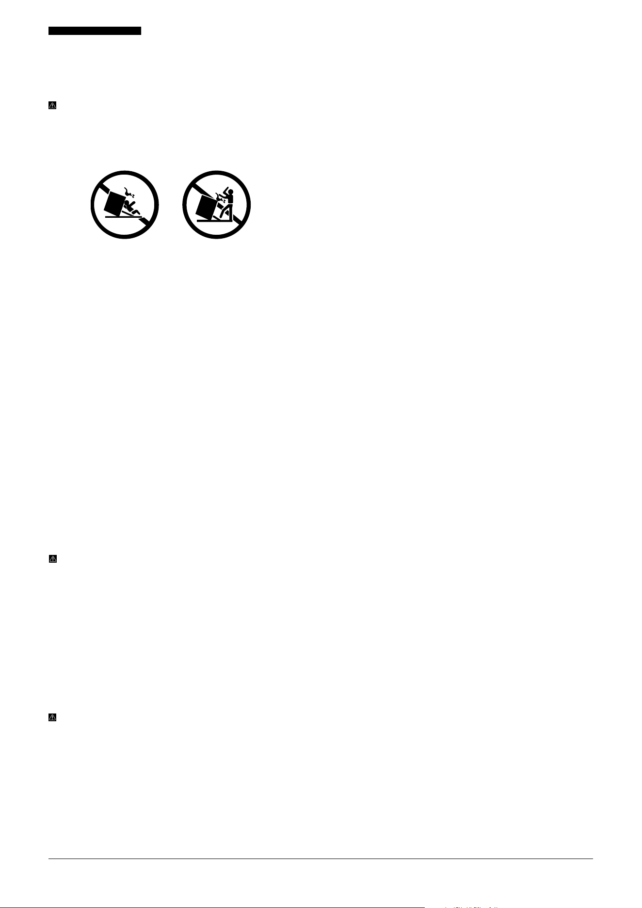
TIPPING SAFETY
Tipping ranges can cause serious injury or death. To reduce
the risk of the range tipping over, it must be secured with a
properly installed anti-tip device. Failure to properly install
the anti-tip device into the wall could result in death or
serious injury to a child or adult.
HOW TO ENSURE PROPER INSTALLATION:
Install the anti-tip device securely to the structure and / or
the range.
Verify the anti-tip device is properly installed and engaged
by sliding the range back toward the wall where the anti-
tip brackets are secured (see “INSTALLING THE ANTI-TIP
BRACKET” instructions on page 26 of the installation
manual).
Engage the range with the anti-tip device by carefully tilting
the front of the range upward slightly and sliding it back so
the mounting pins slide under the brackets.
If the range is moved, always re-engage the anti-tip brackets
before use.
DO NOT operate the range without the anti-tip device
installed and engaged.
WARNING: Failure to follow these instructions can result
in death or serious burns to children or adults.
ALWAYS re-engage the anti-tip device whenever the range
is moved by following the steps outlined above and on page
26 of the installation instructions.
To check the installation, carefully pull the range from the
rear. If the anti-tip brackets are installed correctly, the range
should not tip more than 4" (102 mm) away from the wall.
If the range tips forward more than 4" (102 mm), the anti-tip
device is not installed properly.
DANGER:DO NOT tip the range more than 4" (102 mm)
from the wall, as it could tip over and cause injury.
NEVER completely remove the leveling legs, or the range
may not be properly secured to the anti-tip brackets.
NEVER step or sit on the oven door.
Although the range will not tip during normal use, it can tip
if too much force or weight is applied to the open oven door
without a properly fastened anti-tip brackets.

7001-082525-03 PRG Model USER MANUAL
Warranty Information
COVERAGE
Hauslane gas ranges come with:
A FIVE-YEAR PARTS AND SERVICE WARRANTY
A limited lifetime warranty on burners and spark tips.
The warranty period begins on the original product delivery
date and applies ONLY to the original purchaser of a new
product delivered in its original packaging. The limited
warranty covers all parts to repair defects in materials or
workmanship.
Warranty service applies O NLY to products deemed
serviceable through troubleshooting with the Hauslane
support team.
All warranty service MUST BE authorized and performed
by Hauslane-approved, certified service providers unless
otherwise specified. Service is available during normal
business hours, and the product must be accessible and
unobstructed at the time of service.
Hauslane’s liability is limited to the original purchase price
of the product. Any additional damages, losses, injuries, or
inconveniences caused by product defects or malfunctions
are not covered under this warranty.
TERMS
This warranty applies O NLY to products installed for
normal residential use, defined as a single-family residential
dwelling in a non-commercial setting.
Warranty claims arising from installation, use, or operation
in commercial or non-residential settings are excluded from
coverage. Commercial settings include, but are not limited
to: schools, churches, hotels, restaurants, vacation rentals
(e.g., Airbnb), daycare centers, private clubs, fire stations,
common areas in multi-family dwellings, nursing homes,
food service establishments, hospitals, and correctional
facilities.
This warranty is non-transferable and is valid only from the
original product delivery date, regardless of the installation
date. It applies ON LY to the original purchaser of a new
product installed within the contiguous United States and
the District of Columbia.
To maintain coverage, all warranty procedures MUST BE
strictly followed. Failure to obtain certified warranty service
in accordance with these terms will void the remaining
warranty.
Out-of-pocket expenses for repairs will not be reimbursed
without prior approval from Hauslane or its authorized
service partners. Unauthorized service costs will not be
refunded.
If the product qualifies within the warranty period and
Hauslane cannot repair the product or a defective part
after a reasonable number of attempts, Hauslane may, at
its discretion, either replace the defective part or the entire
product, or provide a full refund of the original purchase
price (excluding installation, removal, or other non-product
charges).
When filing a warranty claim, the original purchaser must
provide proof of purchase showing the purchase date,
along with the product’s serial number. The warranty does
not apply if the factory serial number is missing, altered, or
unreadable.
Hauslane is not responsible for damages resulting from, but
not limited to: shipment, delivery, or improper installation;
negligence, improper maintenance, misuse, or abuse;
unauthorized alteration, modification, or tampering;
accidents, fire, floods, pest infestations, pandemics, natural
disasters, or other “acts of God”; flare-up fires or damages
caused by improper electrical supply, voltage, or power
surges; and service required to correct improper installation
not in accordance with Hauslane manuals or local codes.
WARRANTY EXCLUSIONS AND IMPORTANT
INFORMATION
This warranty does not cover the following:
• Cosmetic damage, scratches, or natural wear from regular
use.
• Second-hand items, open-box products, or products
purchased from unauthorized sellers.
• Damage caused by incorrect liquid propane gas
conversion or related issues.
• Complaints or adjustments related to burner flame
behavior.
• Corrections related to normal settings or local gas supply
problems such as low pressure.
• Damage caused by any modifications, such as painting
parts of the product or cutting the power cord to hardwire
the unit.
• Service needed due to gas pressure issues in high-altitude
installations. Customers are responsible for providing the
correct high-altitude pressure regulator.
If a service visit determines that the issue is not covered
under warranty, the customer must pay all associated
service fees. Failure to pay will result in cancellation of any
remaining warranty coverage.
The information provided in Hauslane installation and user
manuals, as well as product listings on the Hauslane website
and aliated platforms, does not cover every potential
situation that may arise during installation or use. Hauslane
reserves the right to make changes to its products at any
time if deemed necessary and safe.
IMPORTANT: DO NOT install or use any Hauslane product
that is missing parts or arrives damaged. If your product
arrives with damage, contact Hauslane customer service
team at 1-800-929-0168 (8 a.m.–5 p.m., PST, Mon-
day –Friday). or email us at info@hauslane.com before
installation. Failure to report shipping damage before
installation may void your warranty.
8001-082525-03 PRG Model USER MANUAL
This appliance can be used with Propane Gas and Natural Gas. It is shipped
from the factory adjusted for use with natural gas: Conversion orifices are
located in conversion kit small box. Follow the propane conversion
instructions located in the Installation Manual.
400 2621
Conforms to:
CSA /ANSI Z21.1: 2018
CSA 1.1: 2018
Household Cooking Appliance
Model NO.: PRGXX
Date: XXXXXX
Serial No.: SGXXXXXXXXXXX
Warranty Information
Hauslane is not responsible for damage or injury resulting
from improper installation or usage. After the warranty
period ends, Hauslane is not obligated to provide repairs,
refunds, prorated coverage, discounts, or replacements
under any circumstances.
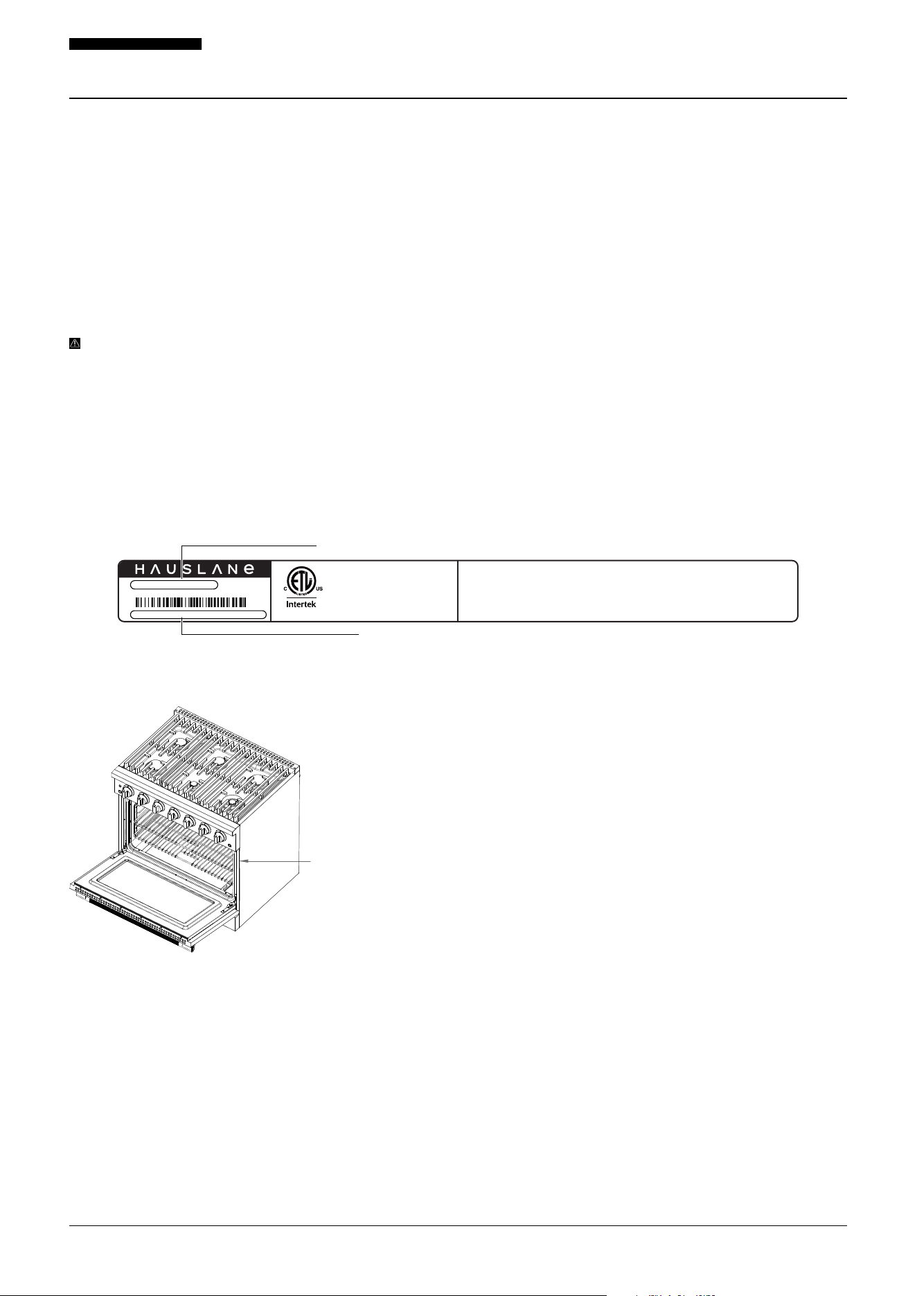
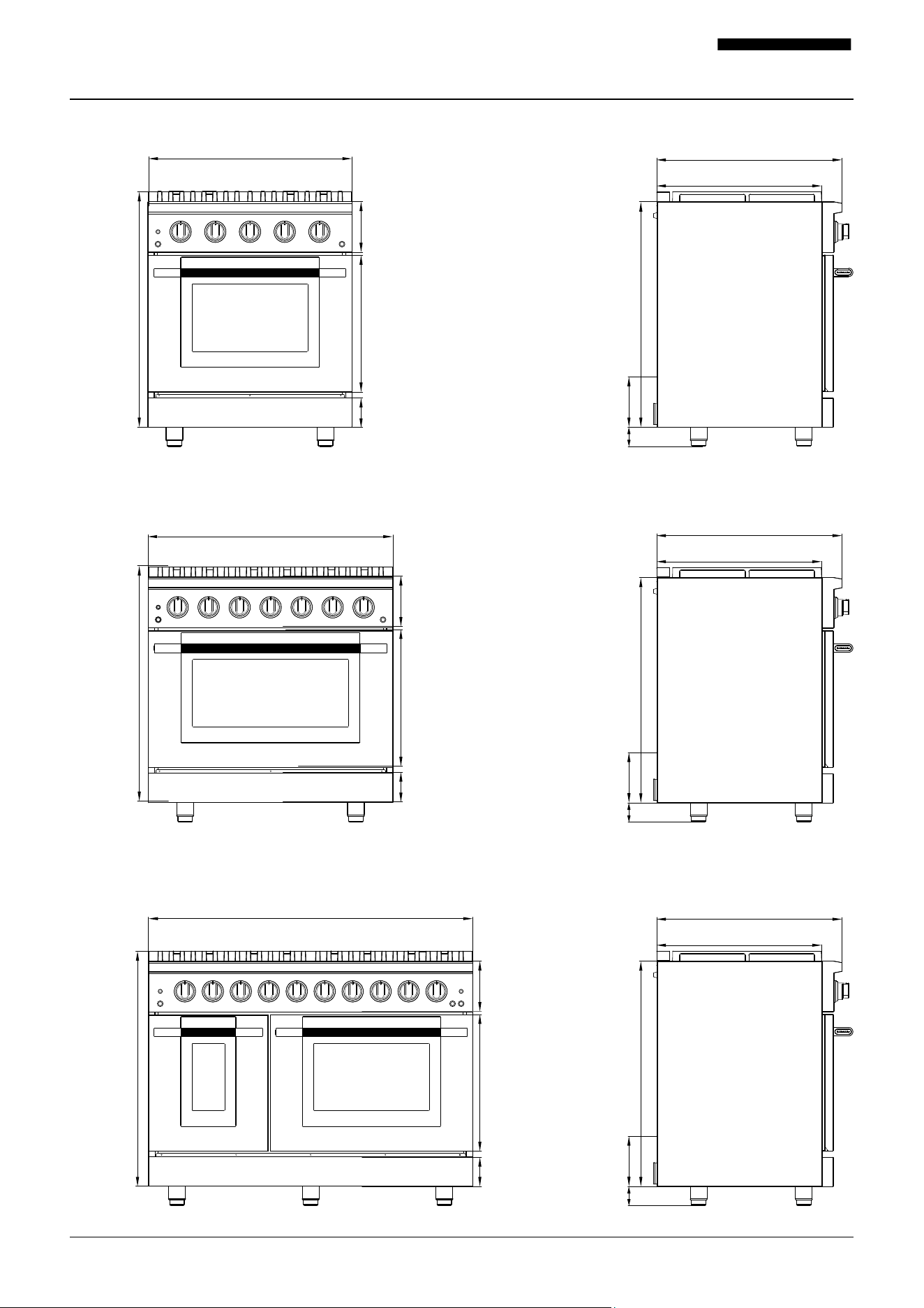
SERIAL NUMBER LOCATION
Please note your appliance’s model number (also called the
“Model NO.”) and serial number for future reference. Both
can be found on the rating tag located on the right front
edge of your range.
IMPORTANT: DO NOT remove any permanently axed
labels, warnings, or plates from the product, as doing so
will void your warranty.
We recommend attaching your purchase receipt or proof of
purchase to this manual for safekeeping.
WARRANTY CLAIM PROCEDURE
If a claimable defect occurs, please contact our customer
service team at 1-800-929-0168 (8 a.m.–5 p.m., PST,
Monday –Friday). or email us at info@hauslane.com.
Before you make your claim call, please ensure that you
have:
• Description of the range
• Proof of sale
• Details regarding the defect
• Name(s) and address(es) of the owner and installer
Claims MUST BE filled out in writing and returned within six
(6) months of the appearance of a defect. Failure to comply
with this stipulation will make this warranty null and void.
We reserve the right to a thirty-day (30) delay following
the receipt of a claim in which to inspect the product.
We assume no responsibility for labor costs, removing or
replacing a previously installed product, transportation, or
the return of a product.
Rating Label Location
Model Number
Serial Number
9001-082525-03 PRG Model USER MANUAL
Specifications
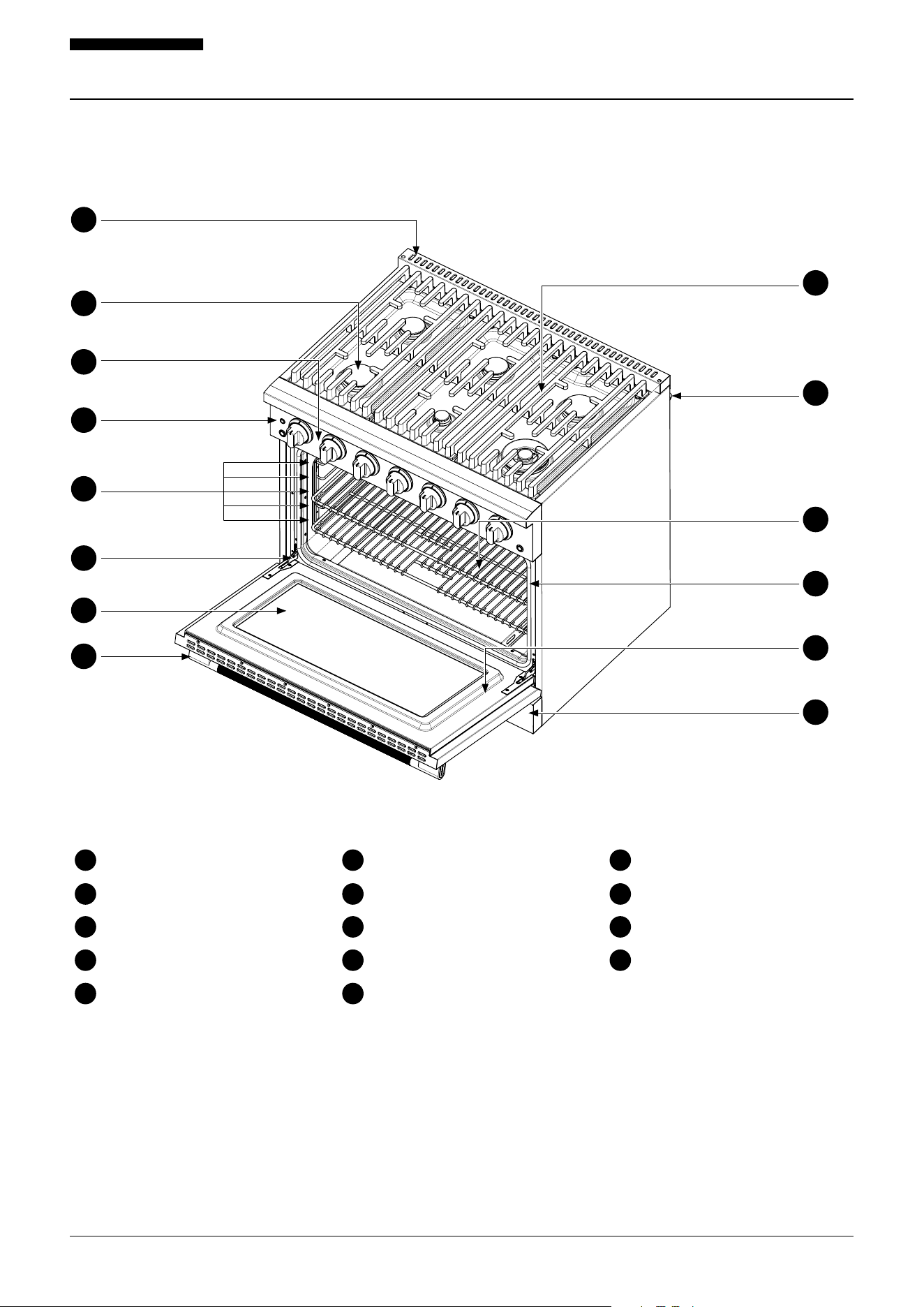
PRG30 Model (Front View and Side View Dimensions)
PRG36 Model (Front View and Side View Dimensions)
PRG48 Model (Front View and Side View Dimensions)
30" (763 mm)
36" (915 mm)
7 ½" (190 mm)
7 ½" (190 mm)
7 ½"
(190 mm)
20 ⅛"
(511 mm)
20 ⅛"
(511 mm)
20 ⅛"
(511 mm)
4 5/16" (110 mm)
4 5/16" (110 mm)
4 5/16"
(110 mm)
35 ⅝"
(905 mm)
47 ⅞" (1216 mm)
35 ⅝"
(905 mm)
35 ⅝"
(905 mm)
27 5/16" (694 mm)
24 ⅜" (619 mm)
2 ¾" (70 mm) to 4 ¼" (108 mm)
33 ¼"
(844 mm)
7 ½"
(190 mm)
27 5/16" (694 mm)
24 ⅜" (619 mm)
2 ¾" (70 mm) to 4 ¼" (108 mm)
33 ¼"
(844 mm)
7 ½"
(190 mm)
27 5/16" (694 mm)
24 ⅜" (619 mm)
2 ¾" (70 mm) to
4 ¼" (108 mm)
33 ¼"
(844 mm)
7 ½"
(190 mm)
10001-082525-03 PRG Model USER MANUAL
Package Contents
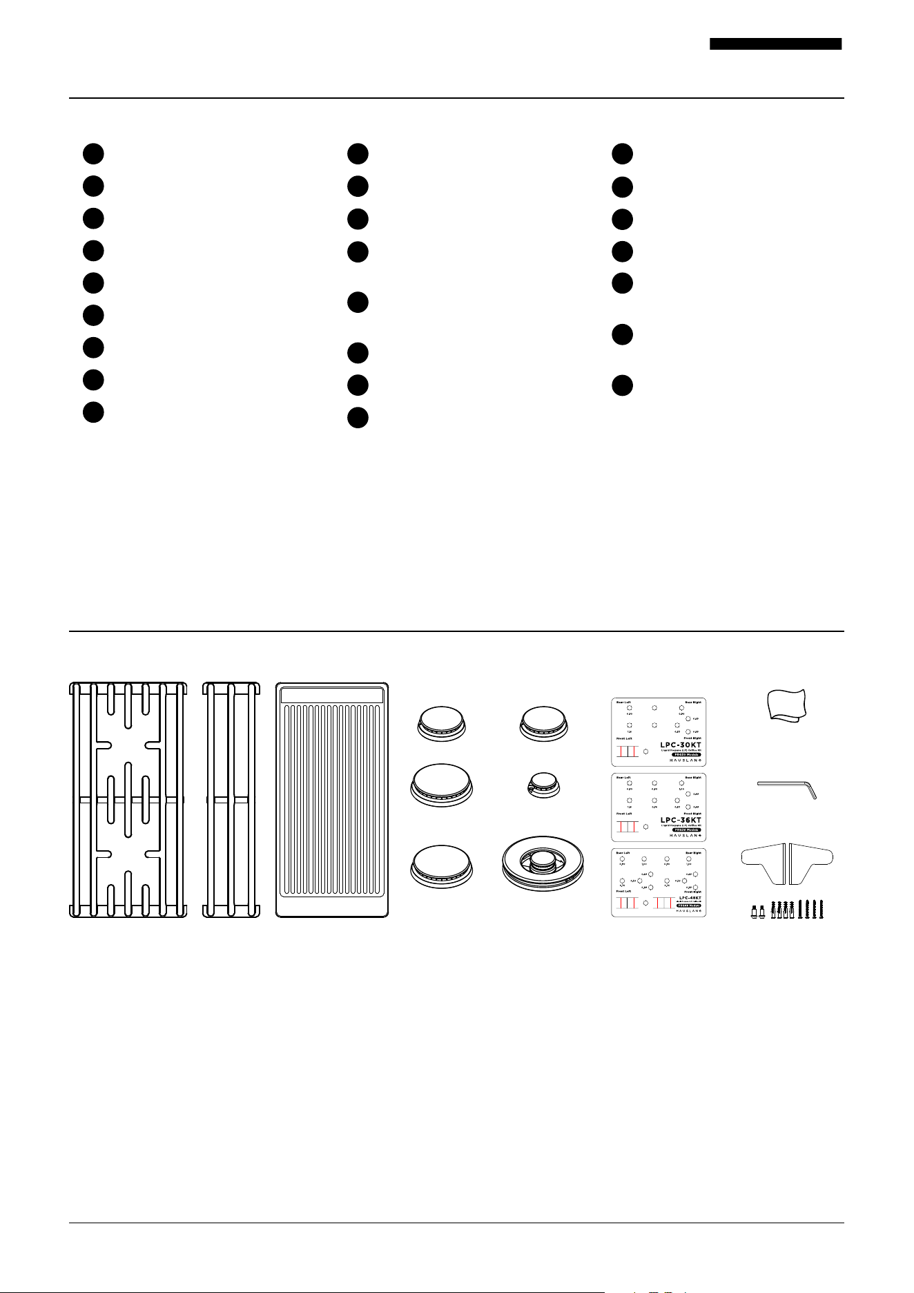
Oven Vent
Burner
Control Panel
Oven Indicator Light
Rack Positions
Door Hinge
Oven Door Window
Oven Door Handle
Grate
Rear Rubber Pad
Rack x 2
Door Gasket
Oven Door
Kick Plate
1
72
83
94
10
5
11
12
13
14
6
10
2
3
1
4
5
6
7
8
14
12
11
13
9
11001-082525-03 PRG Model USER MANUAL
What’s Included
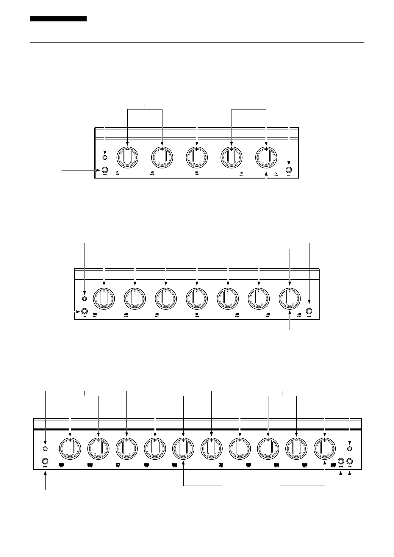
Surface Grates
30" Model: PRG30 (2A + 1B)
36" Model: PRG36 (3A)
48" Model: PRG48 (4A)
Cleaning Cloth
30" Model: PRG30 (1)
36" Model: PRG36 (1)
48" Model: PRG48 (1)
LP Convection Kit
30" Model: LPC-30KT (1)
36" Model: LPC-36KT (1)
48" Model: LPC-48KT (1)
Grate A Grate B Griddle Surface Burners
and Caps
LP Convetion
Kit
Surface Burners and Caps
30" Model: PRG30 (4)
36" Model: PRG36 (6)
48" Model: PRG48 (8)
Griddle (GRD-01)
30" Model: PRG30 (Sold Separately)
36" Model: PRG36 (Sold Separately)
48" Model: PRG48 (1)
Hex Tool
30" Model: PRG30 (1)
36" Model: PRG36 (1)
48" Model: PRG48 (1)
Anti-Tip Bracket
Kit
Hex Tool
Cleaning Cloth
Anti-Tip Bracket Kit
30" Model: PRG30 (1)
36" Model: PRG36 (1)
48" Model: PRG48 (1)
Tools Needed
Measuring Tape
Utility Knife
Philips Screwdriver
Hex Screwdriver
Safety Gloves
Wrench or Pliers
7mm Socket Wrench or Nut Driver
10mm Socket Wrench or Nut Driver
Male ½" or ¾" flare Union Adapter
Aluminum Foil Tape
Pencil or Marker
⅛" (3mm) Flathead Screwdriver
Electric Drill & Extended Length
Head Driver Bit
⅛" (3mm) Drill Bit (for Wood)
Pipe Wrench
15/16" (24mm) Combination Wrench
½" or ¾" MPT Internal Thread Elbow
Allen Wrench / Hex Key (for Handle
Installation) (Included)
Level
Adjustable Wrench
Needle Nose Pliers
Safety Goggles
Pipe-Joint Compound Resistant
to LP Gas
Noncorrosive Leak-Detection
Solution
Manual Gas Line Shut-O Valve
1
9
13
17
2
10
14
18
3
11
15
16
19
4
12
20
21
22
23
24
5
5
7
8
Before you begin the installation process, gather the following tools:
ADDITIONAL PARTS
Check local codes, consult your gas supplier, and check
the existing gas / electrical supply prior to beginning the
installation process.
See the “Electrical Connection” and “Gas Connection”
sections of this manual for further information and
guidance on the additional parts a qualified installer will
need to perform this installation.
12001-082525-03 PRG Model USER MANUAL
Control Panel
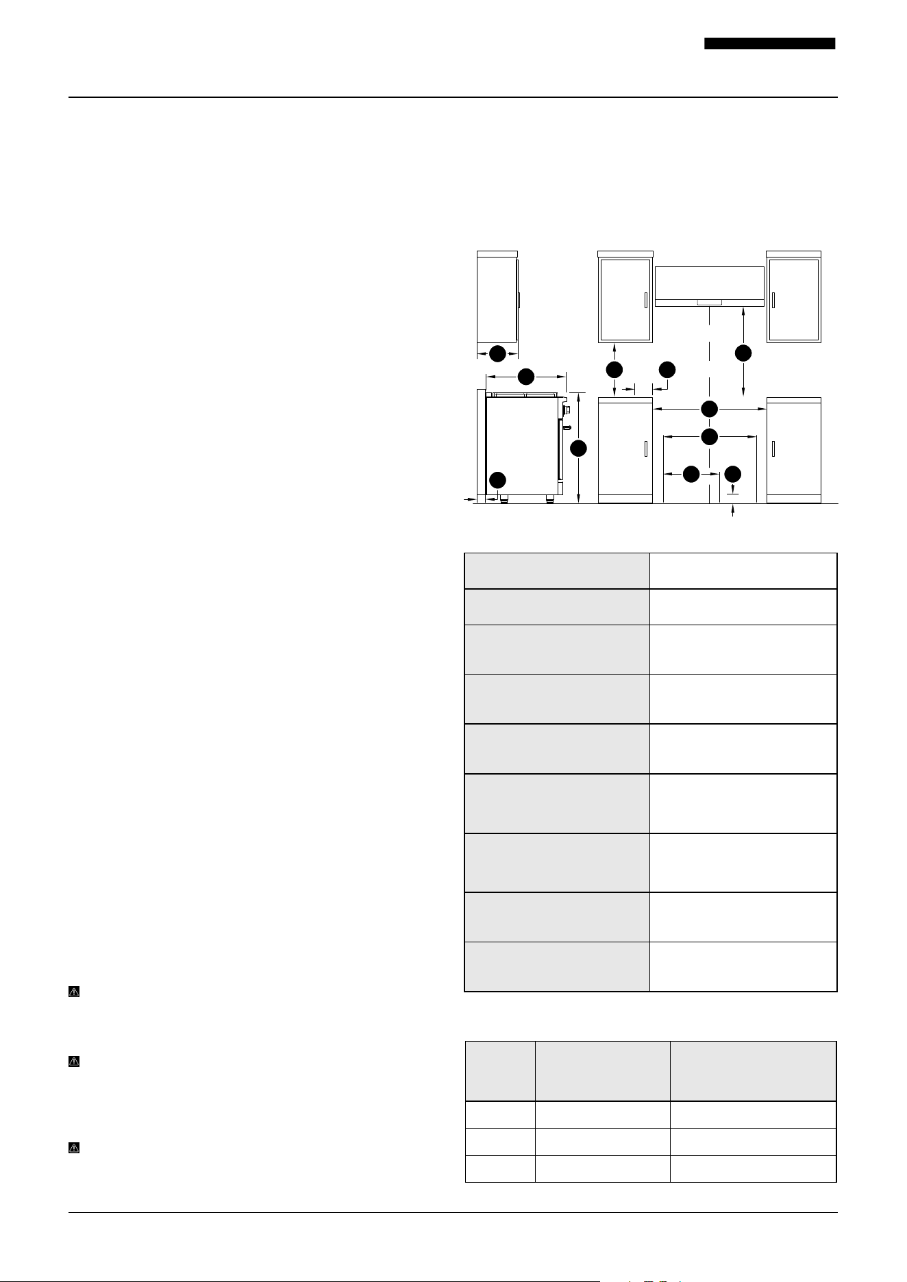
Convection
Fan
Convection
Fan
Convection Fan
Oven Light
Oven Light
Small Oven
Light
Large Oven Light
Oven
Indicator Light
Small Oven
Indicator Light
Oven
Indicator Light
Large Oven
Indicator Light
Small Oven
Knob
Large Oven
Knob
Oven
Knob
Oven
Knob
PRG30 (30")
PRG36 (36")
PRG48 (48")
Before you begin the installation process, gather the following tools:
Cooktop
Knobs
Cooktop
Knobs
Cooktop
Knobs
Cooktop
Knobs
Cooktop
Knobs
Cooktop
Knobs
Cooktop
Knobs
Dual-Ring Burner
Knob Location
Dual-Ring Burner
Knob Location
Dual-Ring Burner
Knob Location
13001-082525-03 PRG Model USER MANUAL
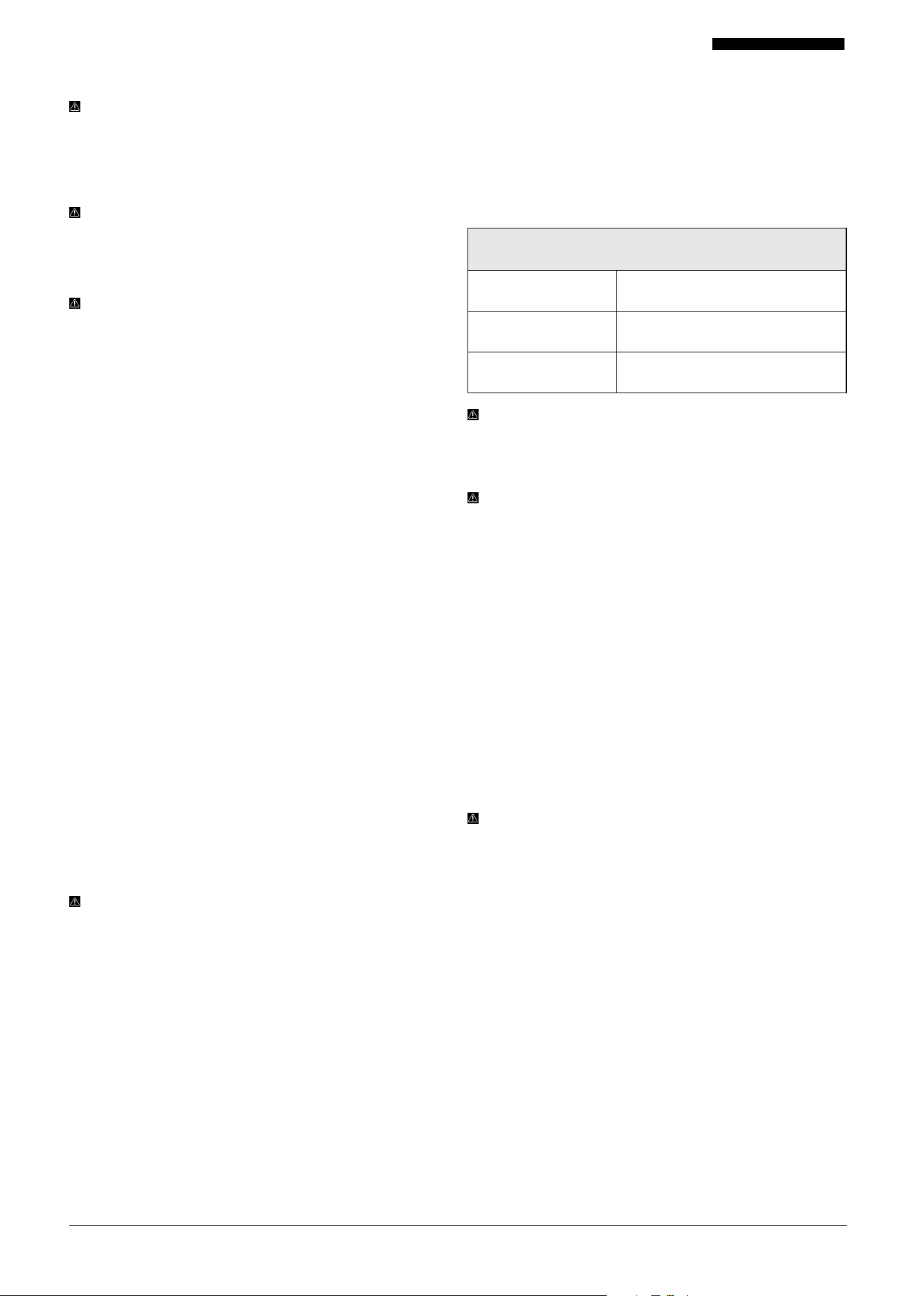
1. Cabinet Depth Above
Cooktop:
13" (330 mm) Maximum
2. Depth from rear of chassis to
front of control panel
27 5/16" (694 mm)
3. Minimum Clearance
(Countertop to Cabinet,
Both Sides of Range)
18" (457 mm)
4. Cooktop Side to Cabinet
Clearance (Adjacent
Working Areas)
6" (152 mm)
5. Minimum Clearance from
Cooktop to Ventilation Hood
30" – 36" (762 – 914 mm)
Depending on Your Hood
Model
6. Cooktop Height from Floor
(to Surface)
37 ½" to 39" (953 – 991 mm)
Depending on Leveling and
Installation Height
7. Gas and Electrical
Connection Area (Maximum
Depth)
Max Depth of Gas / Electric
Rough-in Area: 2 13/16" (71 mm)
from the Rear Wall
8.Gas & Electrical Zone (Width)
PRG30: 22" (Approx.)
PRG36: 28" (Approx.)
PRG48: 39 ⅞" (Approx.)
9. Gas and Electrical
Connection Area (Maximum
Height)
Vertical Space from Floor to
Gas / Electric Rough-in Area: 4
½" (114 mm) from the Floor
Preparation: What to Do Before Installation
Before installing your range, carefully follow these steps:
1. READ THIS MANUAL
Review all safety precautions on pages 1 – 6 of this manual.
Read through all the steps. If you fail to read the instructions
carefully, we will not be responsible for damages incurred
on your part. We recommend hiring a certified technician to
complete the installation.
2. GATHER YOUR TOOLS
Ensure you have all the necessary tools according to the
previous page.
3. INSPECT THE UNIT
Unpack the unit and check your range for damage or
missing parts. Plug it in to an outlet to ensure the fan and
lights work. If anything is damaged or missing, contact
the seller to get the issues solved. DO NOT throw away
packaging until you’re sure you are fully satisfied with the
product.
4. RANGE PLACEMENT
Use the measurements provided on page 13. These
represent minimum clearances from combustible surfaces.
For cabinet cut-out dimensions, refer to page 14.
Ensure that on both sides of the range, the space between
the countertop and the bottom of any upper cabinets is at
least 18” (457 mm). See diagram on page 13.
All wall or floor openings behind the appliance MUST BE
properly sealed.
The floor-mounted anti-tip bracket MUST BE installed. For
installation instructions, see “INSTALLING THE ANTI-TIP
BRACKET” on page 26.
A grounded electrical connection is required. See
the “ELECTRICAL SUPPLY” section on page 15 for
specifications and safety precautions.
Confirm that proper gas supply connections are available.
Refer to the “GAS CONNECTION REQUIREMENTS” section
on pages 17 – 19 and additional gas supply guidelines on
page 14.
Refer to the diagram on page 13 for required gas and
electrical connection locations. The electrical cord length for
all PRG models is 4 feet (1219 mm).
Install the range ON LY under a ducted ventilation hood.
DO NOT install under a downdraft ventilation system.
WARNING: The back of the range may not sit flush against
the wall if gas or electrical connections are installed
outside the recommended placement dimensions.
WARNING: It is the installer’s responsibility to make
sure the appliance is properly adjusted at the time of
installation. Improper installation or adjustment is not
covered under warranty.
WARNING: DO NOT store anything appealing to children
in cabinets above the range. Children may try to climb on
the appliance, leading to serious injury or burns.
5. ENSURE THERE IS PROPER HEIGHT
CLEARANCE
To ensure safe and proper installation, follow these spacing
requirements for your range and ventilation system. Refer to
the visual guide below for reference.
SIDE VIEW & FRONT VIEW DIMENSIONS
OPENING WIDTH AND HOOKUP SPACING
Model
W (Opening
Width)
A (Available Space
- Gas and Electrical
Hookup Zone)
PRG30 30 ¼" (768mm) 15" (381mm)
PRG36 36 ¼" (921mm) 21" (533mm)
PRG48 48 ⅛" (1222mm) 31" (787mm)
FRONT VIEWSIDE VIEW
1
2
3
W
4
5
A 9
7
6
C
8

14001-082525-03 PRG Model USER MANUAL
NOTE: If you are not installing a ventilation hood above
the range, you MUST allow for a minimum clearance of
42" (1067 mm) between the cooktop and any combustible
surface above it.
RECOMMENDED CABINET CUT-OUT DIMENSIONS:
PLANNING NOTE:
WIDTH: These dimensions allow ⅛" (3 mm) clearance on
each side. Adjust based on your kitchen’s exact layout.
DEPTH: Slightly deeper than standard 24" (610 mm) to
allow the oven door to open fully and safely. The extra ¾"
(19 mm) also accommodates back bumpers so the unit can
sit flush against the wall.
HEIGHT: Based on a standard cabinet height of 36" (914
mm) with the appliance legs at their lowest setting. Legs
are adjustable by up to 1 ½" (38 mm) to fit your preferred
working height.
WARNING: OVERHEAD CABINET STORAGE
Avoid placing cabinets directly above the range.
Combustible materials stored above may ignite, and metal
objects may become dangerously hot. If you MUST install
cabinets above the range, reduce fire risk by using a range
hood that extends at least 5" (127 mm) beyond the cabinet
front.
6.CHECK YOUR GAS SUPPLY AND ELECTRICAL
CONNECTION
GAS SAFETY
DANGER:
Serious risk of death, explosion, or fire exists
unless all of the following safety steps are followed during
gas hookup:
• Use a new gas supply line that is CSA International
approved.
• Install a manual gas shut-o valve near the appliance.
• Securely tighten all gas connections using the proper
tools and materials.
• ON LY a qualified professional should perform the
installation. Examples include:
Licensed heating technicians
Authorized gas company representatives
Authorized appliance service personnel
Observe all governing codes and ordinances
IMPORTANT: FOLLOW ALL CODES AND REGULATIONS
This installation MUST comply with all local codes and
ordinances:
• If local codes do not apply, follow the National Fuel Gas
Code ANSI Z223.1 / NFPA 54 (latest edition)
• In Canada, follow CAN/CGA B149 or CAN 1-1.1-M81, as
applicable
• This appliance is design-certified according to ANSI
Z21.1b-201 (latest edition)
• The appliance comes with information about the
maximum inlet gas pressure, which must be adhered to
for safety
• Gas Leak Testing You MUST test all connections for
leaks following the manufacturer’s instructions before
use.
• Gas Line Requirements: Use either: A ½" metal gas line,
or A certified flexible stove connector To seal threaded
connections, use an approved compound resistant to
liquefied petroleum gases to help prevent leaks.
GAS SUPPLY
• NATURAL GAS:
This appliance is designed to operate with natural gas
but can be converted for use with liquid propane by a
qualified technician.
The appliance is factory set for natural gas. Refer to the
model / serial rating plate for approved gas types.
• LIQUID PROPANE GAS:
A qualified service technician must perform any gas
conversion. See page 19 for liquid propane conversion
instructions.
DO NOT attempt to convert the appliance to a dierent
gas type than listed on the model / serial rating plate
without first consulting your local gas provider.
Model Width Depth Height
PRG30
30 ¼"
(768mm)
24 ¾"
(629mm)
36"
(914mm)
PRG36
36 ¼"
(921mm)
24 ¾"
(629mm)
36"
(914mm)
PRG48
48 ⅛"
(1222mm)
24 ¾"
(629mm)
36"
(914mm)
GAS REQUIREMENTS - ALL MODELS
Natural Gas WC
Supply Pressure 5" (12.5 mb)
Minimum Line Pressure 7" (17.5 mb)
Maximum Regulator
Pressure
14" (34.9 mb), 0.5 psi (3.5 kPa)
Liquid Propane Gas WC
Supply Pressure 10" (25 mb)
Minimum Line Pressure 11" (27.4 mb)
Maximum Regulator
Pressure
14" (34.9 mb), 0.5 psi (3.5 kPa)
15001-082525-03 PRG Model USER MANUAL
To avoid electrical shock or damage to the appliance,
installation must be completed by a qualified installer or
certified electrician. The appliance MUST BE properly
grounded. The power supply MUST also have correct
polarity. Reverse polarity can cause continuous sparking of
the electrodes, even after ignition. If you are unsure about
grounding or polarity, have the power supply inspected by a
licensed electrician.
GAS CONNECTIONS
IMPORTANT:
NEVER apply pressure directly to the
appliance’s manifold pipe when tightening supply
connections. Always support the pressure regulator with
a wrench to prevent twisting. Twisting the manifold pipe
can cause it to split and result in a dangerous gas leak.
NOTE: Check all piping connections for leaks using a soap
solution (75% water, 25% dish soap). Factory connections
can loosen during shipping due to vibration. Inspect all
connections carefully and repair any that leak.
DANGER: NEVER use an open flame to check for gas
leaks.
The appliance and its individual shut-o valve must be
disconnected from the gas supply system during any
pressure testing at pressures above ½ psig (3.5 kPa).
For pressure testing at or below ½ psig (3.5 kPa), the
appliance must be isolated by closing its manual shut-o
valve.
GAS LINE SHUT-OFF VALVE
To help prevent gas leaks, apply Teflon tape or an approved
thread compound for natural gas or liquid propane to all
threaded fittings.
Install a properly sized, agency-approved manual gas
shut-o valve in an accessible location outside the range.
This valve MUST BE located in the gas line leading to the
appliance and allow for quick gas shuto when needed.
This valve is not included with the appliance and MUST BE
supplied by the installer.
For PRG30 and PRG36 ranges, install a ½" male flare union
adapter. For PRG48 ranges, install a ¾" male flare union
adapter. Connect to the ½" or ¾" MPT internal thread elbow
at the regulator inlet. Use a wrench on the regulator fitting
to avoid damage.
Install a ½" or ¾" male flare union adapter into the MPT
thread of the manual shut-o valve. Make sure the valve is
held securely to prevent it from turning during installation.
ELECTRICAL SUPPLY
DANGER: ELECTRIC SHOCK HAZARD
Failure to follow these electrical instructions can result in
death, fire, serious injury, or electrical shock.
Any additions, changes, or conversions required for this
appliance MUST BE performed by a qualified service
technician. All work MUST follow the manufacturer’s
instructions as well as local codes and regulations. The
technician performing any gas or electrical conversion is
responsible for ensuring proper and safe operation of the
appliance.
Do NOT operate this appliance with a 2-prong adapter or an
extension cord. If your wall outlet is not a properly grounded
four-prong receptacle, it must be replaced by a licensed
electrician. If only a 2-prong outlet is available, the consumer
must have it replaced by a qualified electrician with a
properly grounded 3-prong receptacle.
ELECTRICAL REQUIREMENTS
- ALL MODELS
Electrical Supply 120 VAC, 60Hz
Service 15-Amp Dedicated Circuit
Total Amps 9
WARNING: This range is equipped with a 3-prong NEMA
14-50P plug to protect against electrical shock. DO NOT
cut or remove the plug — it MUST BE plugged directly into
a properly grounded wall receptacle.
CAUTION: WHEN SERVICING THE APPLIANCE:
ALWAYS label wires before disconnecting
Incorrect wiring can cause improper or dangerous
operation
After service is complete, verify all functions are working
correctly
7.PRE - INSTALLATION SPECIFICATIONS AND
INSTRUCTIONS
Before starting installation, carefully read and follow the
safety precautions outlined on pages 1 – 6.
Each installation step includes specific safety instructions;
however, it’s important to read all safety guidelines in full.
It is the installer’s responsibility to follow all clearance
requirements outlined in this manual.
WARNING: RANGES ARE EXTREMELY HEAVY (OVER
200 LB / 91 KG).
TO AVOID INJURY OR DAMAGE:
Use proper lifting equipment and adequate manpower when
moving the appliance.
Use caution with the adjustable steel legs — they can be
damaged if the unit is dragged or dropped.
Damage caused by improper handling may not be covered
under warranty.
INSTALLATION PREP TIPS:
Choose a location that meets all safety and installation
requirements specified in the manual.
Carefully unpack the appliance and all parts (including
burners, burner caps, and cooking grates). Check that all
parts listed on page 11 are included and set them aside.
Gather all necessary tools as listed in the “TOOLS NEEDED”
section on page 11.
16001-082525-03 PRG Model USER MANUAL
WARNING: NEVER lift the range by the oven door handle.
Doing so may lead to personal injury or damage to the
door and handle, which may void the warranty.
How to Install Your Range
When you’ve completed all the preparation steps, you’re
ready to install your range.
1. TEST THE UNIT
Plug the unit into an outlet and press the touch panel to
make sure that the unit is working.
IMPORTANT: If the range hood is not working properly,
please contact us immediately (1-800-929-0168 /
info@hauslane.com).
DANGER: TIPPING RANGES CAN CAUSE SERIOUS
INJURY OR DEATH.
TO PREVENT THIS:
The range MUST BE secured with a properly installed anti-
tip bracket.
Failing to attach the anti-tip bracket to the wall correctly can
result in fatal injury to a child or adult.
HOW TO CHECK ANTI-TIP INSTALLATION
To prevent tipping, the anti-tip device MUST BE properly
installed. Secure it to the wall or the range as instructed
in the installation manual. Then, tilt the front of the range
slightly upward and slide it back into its final position,
ensuring that the mounting pins slide under the brackets.
IMPORTANT: DO NOT operate the range without the anti-
tip device engaged. Failure to follow this instruction can
result in serious injury or death.
After moving or repositioning the range, ALWAYS re-engage
the anti-tip device by following the steps outlined on page
26 of the installation manual.
To test the anti-tip installation, gently pull the range from
the back. If installed correctly, the range should not tip
forward more than 4" (102 mm) from the wall. If it tips more
than that, the anti-tip bracket is not properly secured and
must be corrected before using the appliance.
DANGER: DO NOT allow the range to tip more than 4"
(102 mm) from the wall — it may fall forward and cause
injury.
IMPORTANT INSTALLATION TIPS:
NEVER remove the leveling legs — the anti-tip device relies
on them to secure the unit.
NEVER stand or sit on the oven door.
The range is designed not to tip under normal use.
However, if the anti-tip bracket is missing or loose, applying
weight to an open door can cause the entire unit to tip
forward.
2. INSTALLING PARTS
BURNER SPREADS AND CAPS
After unpacking the range, set the cast iron grates aside and
remove the burner spreads and caps from the storage area
beneath the grates.
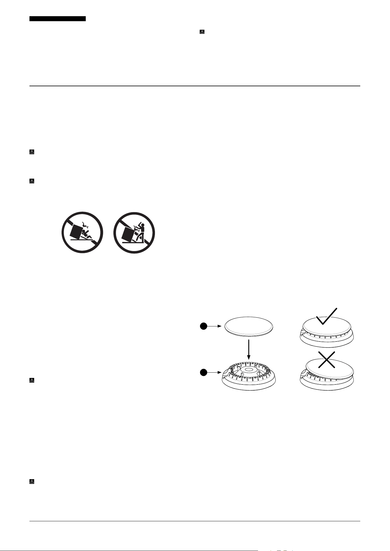
Place each burner spread on the correct burner, ensuring
the hole fits securely over the white metal electrode spark
tip. Then place the burner cap on top until it sits snugly.
If burner spreads (B) or caps (A) are not correctly
positioned, burners may fail to ignite or O N LY ignite
partially, as shown below:
CAST IRON GRATES
Place the cast iron grates on the cooktop, being careful not
to scratch the porcelain surface. Each grate has rubber feet
and aligns with slots on the cooktop.
The PRG48 model includes a reversible enameled cast iron
griddle. It should be placed vertically (front to back) over
any of the four grates. DO NOT place it horizontally (side to
side) across multiple grates.
DO NOT remove the protective film from the appliance
until installation is complete—this helps prevent damage or
scratches to the stainless steel, glass, or porcelain surfaces.
A
B
17001-082525-03 PRG Model USER MANUAL
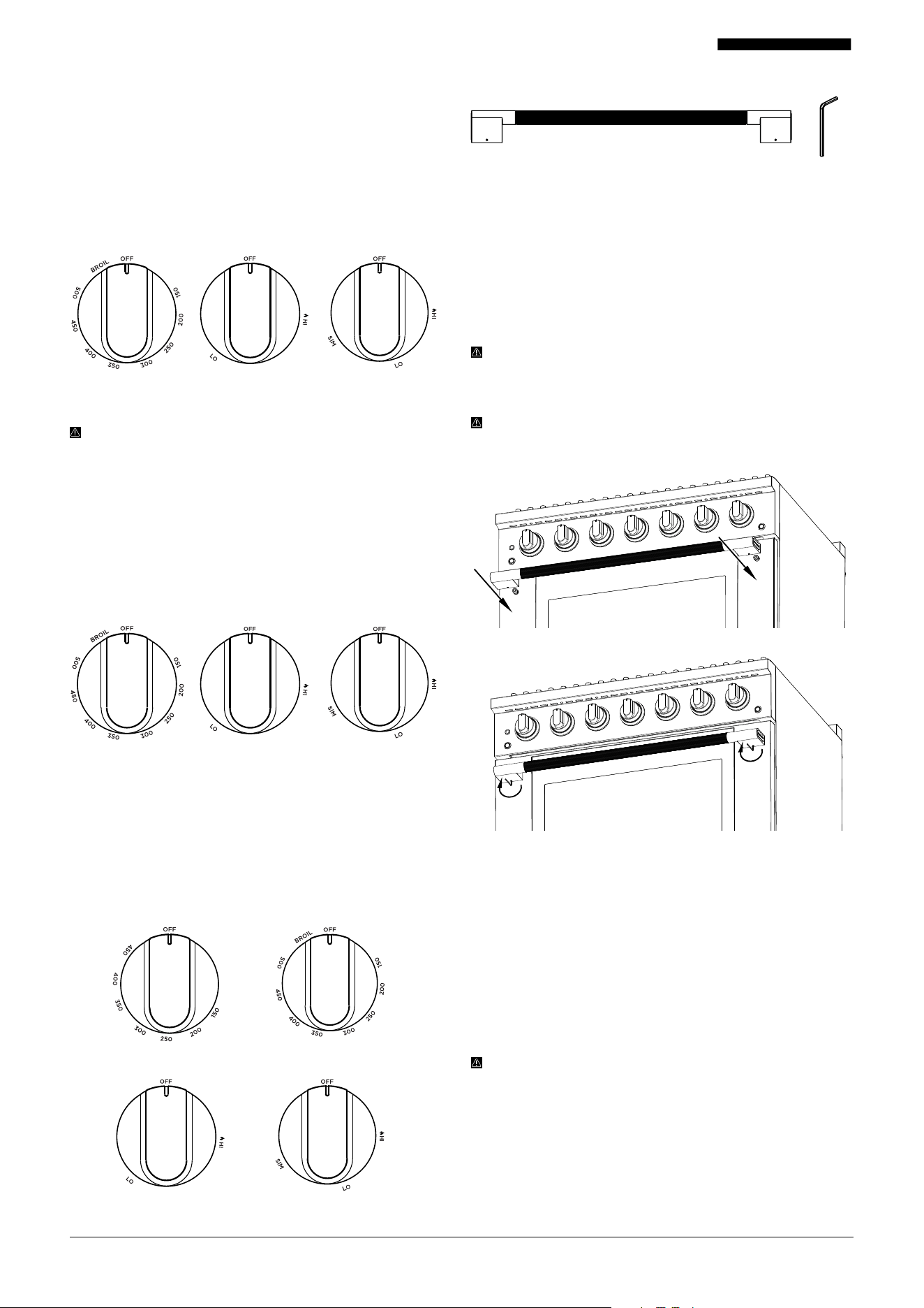
To install the oven door handle, align each bracket with the
pre-installed mounting studs on both sides of the oven door,
as shown in Figure 1 below.
Once aligned, locate the screw holes on the underside of
each bracket base. Using the provided 7/64" (3 mm) Allen
wrench or hex key, tighten both screws until the handle is
securely in place, as shown in Figure 2 below.
If installed properly, the handle should sit perfectly level.
NOTE: While the diagram shows the PRG36 model, the
handle installation process is the same for PRG30 and
PRG48 ranges.
WARNING: Use care to not overtighten, or you risk
stripping the screws and then your handle may be
unstable or fall o, increasing the risk of injury or burns.
KNOBS
1. PRG30 RANGE KNOBS (5 TOTAL)
To install the knobs, align each in the “OFF” position and
press it straight onto the valve stems extending from the
front of the cooktop, as shown at right.
The oven knob installs on the center valve, with burner
knobs placed on either side. The dual function knob goes on
the far right.
WARNING: The PRG30 and PRG36 ranges come with 1
brass dual function burner, and the PRG48 range includes
2 brass dual function burners. The burner knobs for those
include a “SIM” setting, as outlined in the images below.
2. PRG36 RANGE KNOBS (7 TOTAL)
The oven knob installs on the center valve, with burner
knobs placed on either side.
The dual function knob installs on the far right side of the
range.
3. PRG48 RANGE KNOBS (10 TOTAL)
The oven knobs attach to the two center single valves—the
small oven knob on the left and the large oven knob on the
right. Place individual burner knobs on either side of the
oven knobs. One dual function knob goes directly to the left
of the small oven knob, and the other goes on the far right
side of the range.
INSTALLING THE HANDLE
Oven
Knob (1)
Oven
Knob (1)
Single Ring
Burner Knobs (3)
Single Ring
Burner Knobs (5)
Figure 1
Figure 2
Dual Rings
Burner Knobs (1)
Dual Rings
Burner Knobs (1)
3. GAS CONNECTION REQUIREMENTS
This range is factory set to operate on natural gas
(NG). If you intend to use liquid propane gas (LPG), the
conversion MUST BE completed by a qualified installer
before operating the appliance.
All gas connections must comply with national and local
building codes. When using a flexible gas line connector,
make sure the range is positioned so that it can connect
easily to the manual shut-o valve.
DANGER:
MANUAL GAS SHUT-OFF VALVE REQUIRED
The gas supply line must include an approved manual
shut-o valve.
The shut-o valve must be easily accessible, located in the
same room as the appliance.
DO NOT block access to the shut-o valve.
Be sure you know how and where to turn o the gas in
case of emergency.
Small Oven Knob (1)
Single Ring
Burner Knobs (6)
Dual Rings
Burner Knobs (2)
Large Oven Knob (1)
18001-082525-03 PRG Model USER MANUAL
IMPORTANT: The pressure regulator, located at the gas
inlet of the appliance, MUST remain in the supply line
regardless of whether you are using natural gas or liquid
propane.
The regulator is shipped with a clear plastic shield
covering the inlet to prevent debris. This shield must be
removed before connecting the gas line or coupler.
A flexible metal appliance connector should not exceed
3 feet (36 inches or 914 mm) in length for proper
installation. In Canada, flexible connectors must be single-
wall metal and less than 6 feet (1829 mm) in length.
WARNING: EXPLOSION HAZARDS
Read all safety precautions on pages 1 to 6 before
beginning installation.
ON LY use a CSA-approved gas supply line.
Install an approved manual shut-o valve.
Securely tighten all gas connections.
For liquid propane (LPG) installations, a qualified person
must verify that the gas pressure does not exceed 3.5
kPa (14 inches W.C.P.). Qualified persons may include
licensed heating professionals, gas company personnel, or
authorized service technicians.
Failure to follow these instructions may result in fire,
explosion, or death.
GAS INSTALLATION STEPS
1. Shut o the main gas supply before removing an existing
appliance (if applicable). Leave it o until the new range is
fully installed. DO NOT forget to relight pilot lights on any
other gas appliances after restoring gas service.
2. Use a flexible metal connector (CSA-certified) to allow for
movement, unless your local codes require hard piping.
• NEVER reuse an old gas connector.
• If using hard piping, carefully align all fittings.
• Use pipe-joint compound rated for natural gas on all
male pipe threads.
3. Connect the flexible gas line to the ½" regulator fitting
located on the bottom left corner of the range (rear view).
4. Once connected:
• Make sure all range controls are in the OFF position.
• Turn on the main gas supply valve.
• Check for leaks using a 75% water / 25% dish soap
solution.
• If bubbles appear, shut o the gas, tighten all
connections, and retest.
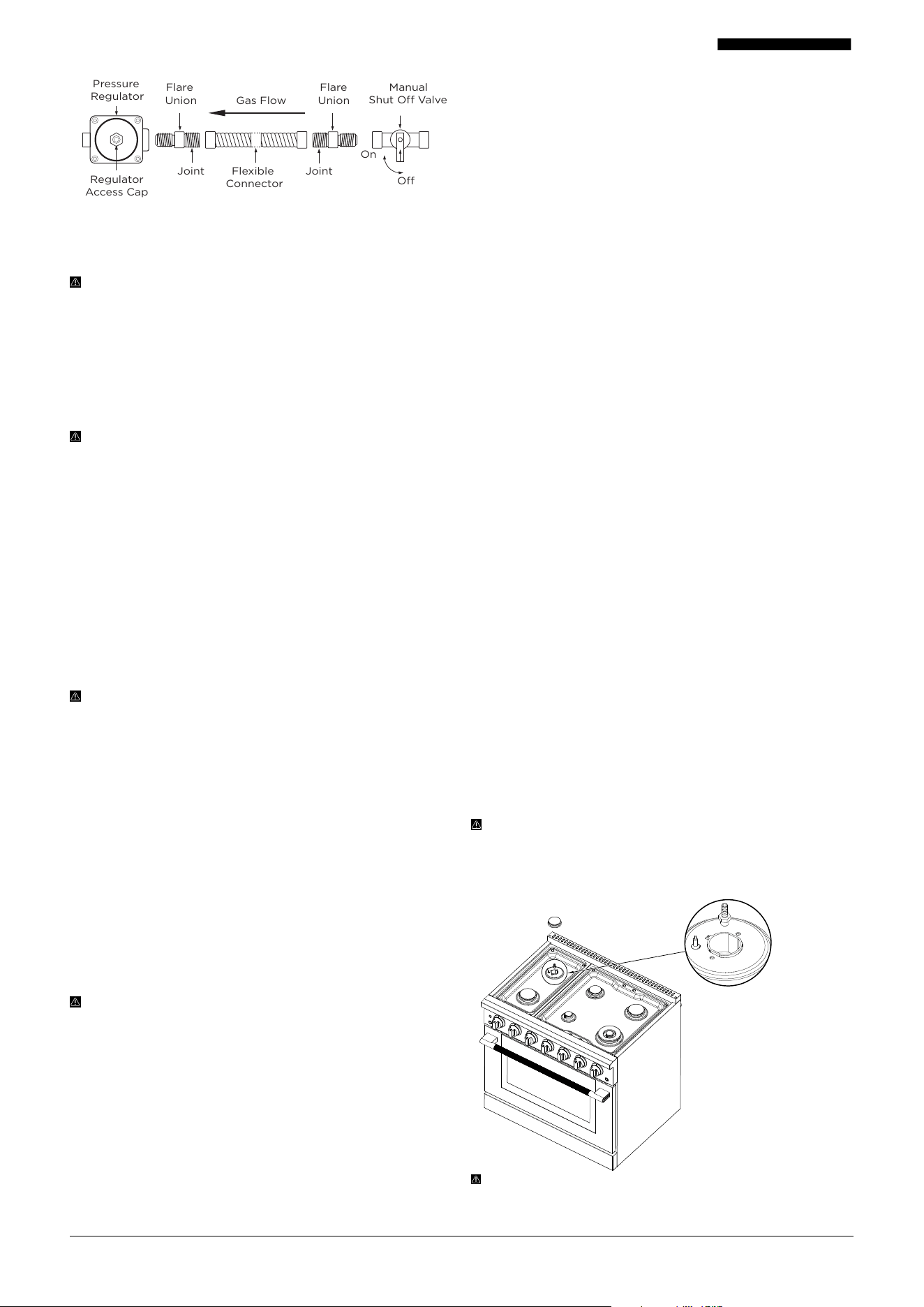
WARNING: ALWAYS connect the gas line through the ½"
fitting on the side of the pressure regulator, as shown in
the diagram on the next page.
DO NOT remove the regulator access cap to connect gas.
This cap is used only for:
• Liquid propane (LP) conversions
• Pressure adjustments
The regulator access cap MUST stay on at all times and
should only be hand-tightened. Removing or tampering
with this cap outside of its intended use may result in unsafe
operation.
Regulator Location and Connection Notes
On all PRG series ranges, the pressure regulator is located at
the bottom right corner when facing the front of the unit.
• From the rear view, the regulator appears on the
bottom left.
• The diagram on the next page shows:
• Proper gas hookup flow
• Fitting locations
• Required parts for connection
NOTE: The regulator and access cap are factory-installed.
Other connection components, such as flare unions, shut-
o valves, and flexible connectors, MUST BE supplied by
the installer or customer.
IMPORTANT: The regulator access cap is used O N LY for
liquid propane (LP) conversion or pressure adjustment. It
is not for gas hookup. The cap should always be hand-
tightened and remain in place during installation and
operation.
SAFETY AND EXPLOSION HAZARDS
Read all safety precautions on pages 1 to 6 before
proceeding.
NEVER use an open flame to check for gas leaks. Doing so
may result in a fire or explosion.
Tighten all connections securely to prevent leaks in the
appliance or the gas supply line.
After connecting the gas line:
• Check that the control knobs align properly with their
valve stems. Misalignment could mean the manifold
pipe has shifted, which may cause the valve stems to
rub against the control panel and create a gas leak.
During pressure testing:
• During any test pressure equal to or less than ½ psig
(3.5 kPa), the appliance and it's shut o valve must
disconnected from the main gas line.
Refer to the gas hookup diagram on the next page for
proper connection flow and fitting locations. The pressure
regulator and its access cap are pre-installed. All other gas
connection components MUST BE supplied by the customer
and installed by a qualified technician to ensure a safe and
compliant installation.
19001-082525-03 PRG Model USER MANUAL
4. LIQUID PROPANE CONVERSION
PROCEDURE (OPTIONAL)
CAUTION: SHUT OFF GAS AND POWER FIRST
Before beginning the conversion:
• Turn o the gas supply to the appliance
• Then disconnect the electrical power
• DO NOT attempt the conversion while the appliance is
connected to either gas or electricity.
IMPORTANT NOTES
If you plan to use liquid propane (LPG), the conversion
MUST BE completed before installing the anti-tip device.
If you’re using factory-installed natural gas and DO NOT
need to convert to propane, you can skip ahead to page
24.
Your appliance comes with a conversion kit. Be sure to use
the correct one based on your model:
PRG30: LPC-30KT
PRG36: LPC-36KT
PRG48: LPC-48KT
WARNING: SAFETY MEASURES
Read all safety precautions on pages 1–6 before
proceeding.
The conversion MUST BE completed by a qualified service
technician, following both the kit instructions and local
codes.
Skipping this conversion when using LPG may result in
serious injury or property damage.
The service agency performing the conversion is
responsible for its accuracy and safety.
Once converted, the LPG gas supply MUST provide:
Minimum: 2.5 kPa (10” W.C.P.)
Maximum: 3.5 kPa (14” W.C.P.)
WARNING: QUALIFIED INSTALLATION REQUIRED
This conversion kit MUST BE installed by a qualified
service agency in full accordance with:
• The manufacturer’s instructions
• All applicable building codes and regulations
If these instructions are not followed exactly, the result
may be:
• Fire
• Explosion
• Carbon monoxide production
• Serious injury or loss of life
The installation is not complete until the converted
appliance has been tested and verified for proper operation
as described in the conversion kit instructions.
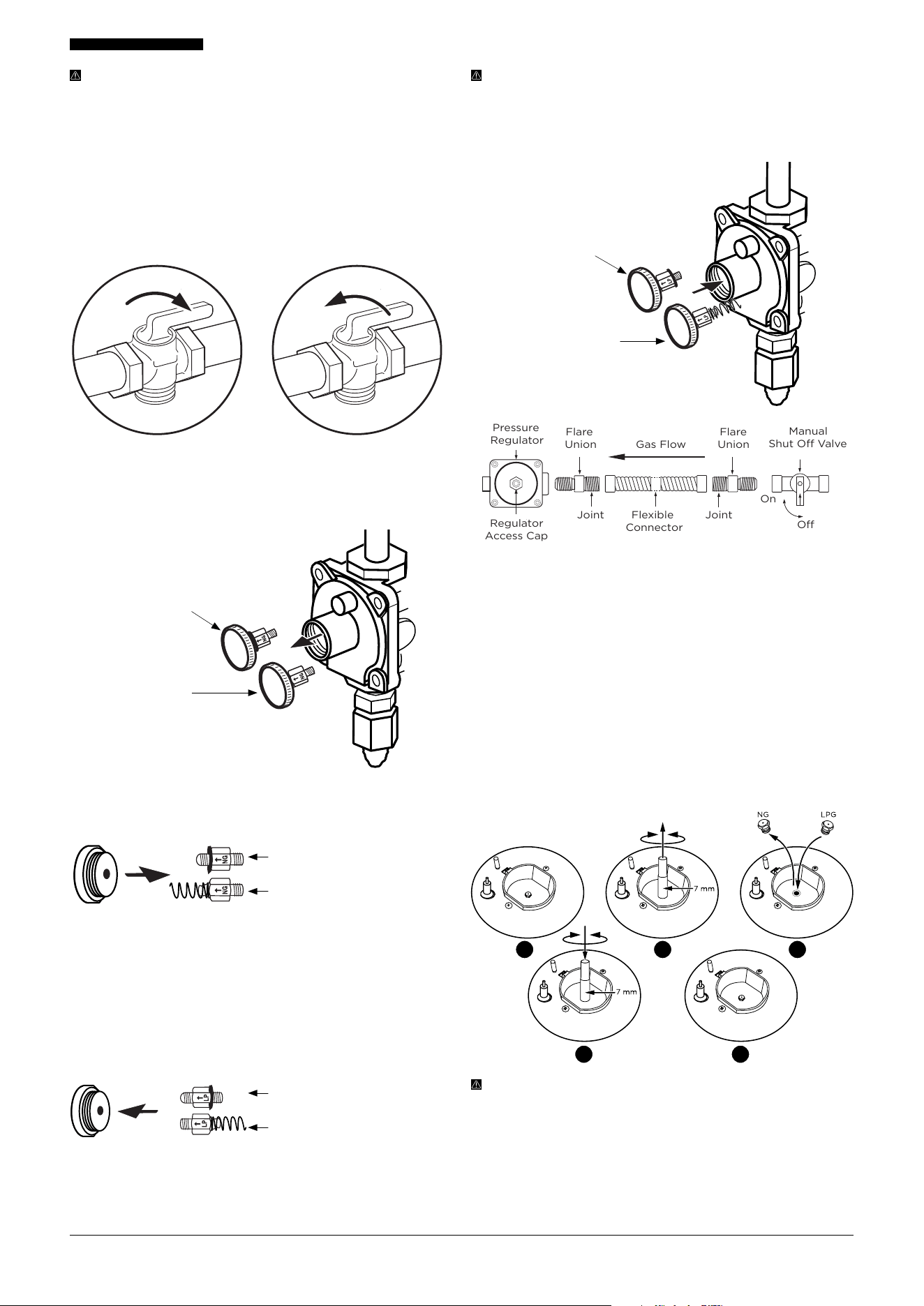
CHECKING MANIFOLD PRESSURE
A licensed technician should check manifold pressure using:
• Their own manometer
• A Hauslane-supplied test point adapter
• ¼" (6 mm) tubing
The figure references the PRG36 range, but the procedure is
the same for all PRG models.
To perform the test:
1. By hand, remove the burner spread and burner cap
from either the rear left or front left burner on the
cooktop.
2. Using a 9/32" (7 mm) nut driver or wrench, remove the
gas orifice from the bottom of that burner.
3. Insert the test point adapter into the orifice hole.
4. Turn the burner control knob to the “HI” position.
5. While pressing and holding the knob, use the
manometer to check the pressure.
TARGET MANIFOLD PRESSURES:
Natural Gas: 1.2 kPa (5 inches W.C.P.)
Liquid Propane Gas: 2.7 kPa (11 inches W.C.P.)
The upstream line pressure must be at least 0.25 kPa (1 inch
W.C.P.) higher than the manifold pressure for an accurate
reading.
The pressure regulator on this appliance can safely accept
up to 3.5 kPa (½ PSI or 14 inches W.C.P.) of input pressure. If
the line pressure exceeds this value, a step-down regulator
MUST BE used.
CAUTION: TEST ONLY SIDE BURNERS
DO NOT perform pressure testing on dual function
burners. ONLY use one of the far-left burners on the range
for accurate pressure readings.
If your LP conversion kit did not include the test point
adapter or ¼" tubing, contact Hauslane Customer
Experience at 1-800-929-0168 for assistance.
Remove the burner
spread and burner cap
by hand. Insert the test
point adapter into the
orifice hole.
JointJoint
Flexible
Connector
Off
On
Gas Flow
Regulator
Access Cap
Pressure
Regulator
Flare
Union
Flare
Union
Manual
Shut Off Valve
20001-082525-03 PRG Model USER MANUAL
DANGER: ALWAYS disconnect electrical power to the
appliance before performing any service. Failure to do so
may result in shock, fire, or death.
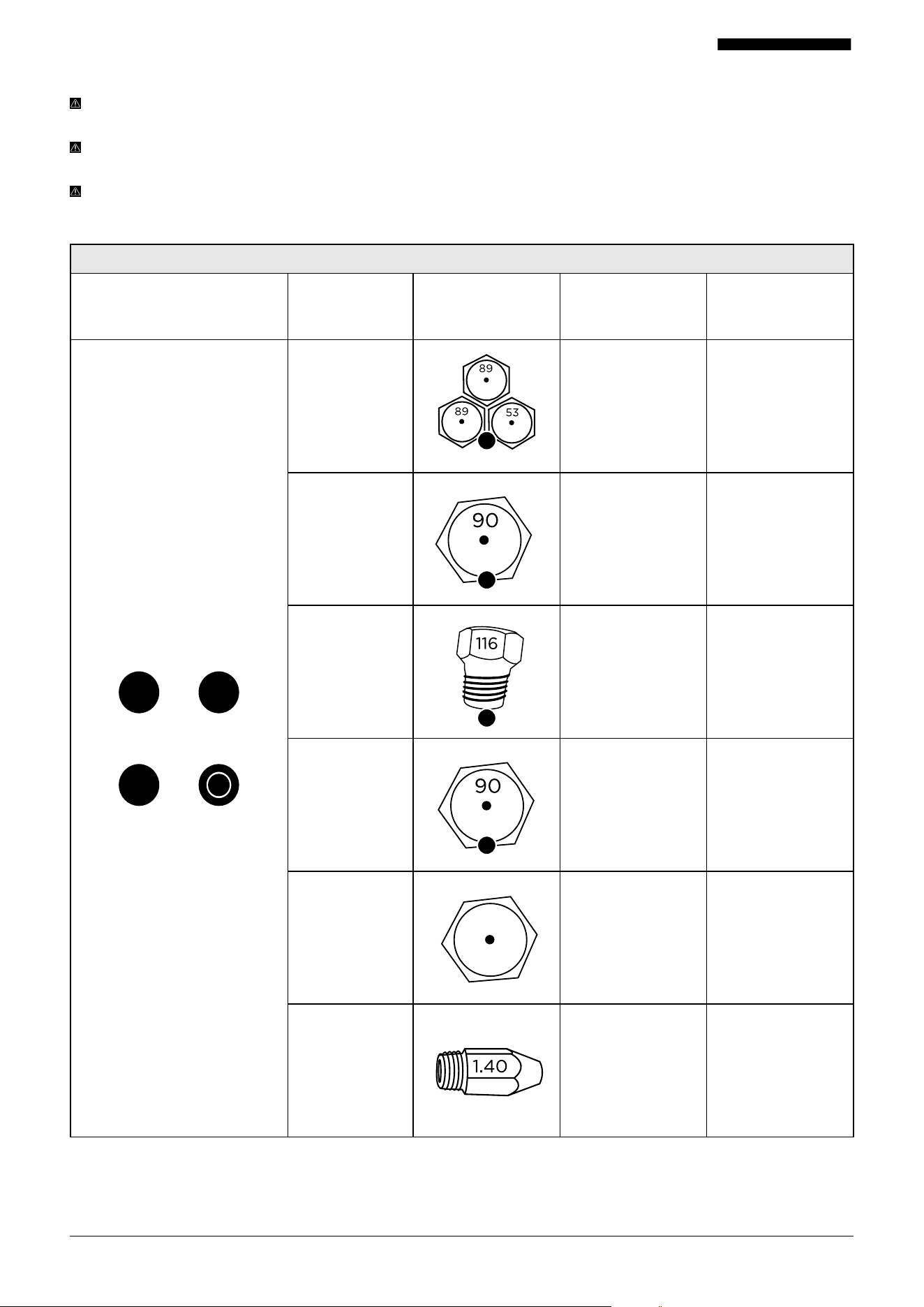
STEPS TO ADJUST THE REGULATOR FOR PROPANE USE:
Shut o the gas supply by closing the manual shut-o valve.
Purge the gas line by pressing the range knobs several times
— this ensures no gas remains in the system.
Unscrew the regulator access cap by hand or with a suitable
pipe wrench (refer to diagram).
Remove the regulator pin (See diagram below):
PRG30 and PRG36
Models: The pin is
GR AY
PRG48 Model: The
pin is GOLD
You’ll reinstall this pin in the correct position based on
your gas type — the next section will guide you through it.
For PRG30 and PRG36 models, locate the gray regulator
pin. It is not attached to a spring. Unscrew the pin, flip it
over, and screw it back into the regulator cap as shown in
the diagrams. For PRG48 model, the gold regulator pin
is attached to a spring. Unscrew the pin, reverse it, and
screw it back into the regulator cap. Make sure the spring
fits snugly when tightening to ensure proper pressure
regulation.
Once the pin is reversed, screw the regulator access cap
back into the regulator body. Then reconnect the regulator
to the nipple and flare union as illustrated. DO NOT
overtighten.
PRG30 and PRG36 Models
PRG48 Model
NOTE: The pressure regulator and cap come pre-installed
on your unit. All other gas connection parts shown in
the diagram (flare unions, shut-o valve, etc.) MUST
be supplied by the customer for a qualified installer to
complete the hook-up safely.
PRG30 and PRG36
Models: The pin is
GR AY
PRG48 Model: The pin
is GOLD
CHANGING BURNER ORIFICES
First, remove the burner grates, burner caps, and burner
spreads. Then use a 9/32" (7 mm) nut driver or wrench to
unscrew the existing natural gas orifices. Each orifice is
labeled for its correct location, so read the labels carefully
before replacing.
Replace each with the matching liquid propane orifice. DO
NOT force or overtighten the orifices, as this can damage
the burner base and aect flame performance.
For dual burners, there are three orifices per burner. One is
in the center and two are located on the sides. Use a 9/32" (7
mm) wrench to remove and replace the side orifices as well.
WARNING: HANDLE GAS COMPONENTS WITH CARE
Save all removed natural gas orifices — you will need them
if converting back to NG in the future.
Be careful when handling metal components, especially
sharp or threaded parts.
Use proper tools and support to avoid damaging the
appliance during conversion.
JointJoint
Flexible
Connector
Off
On
Gas Flow
Regulator
Access Cap
Pressure
Regulator
Flare
Union
Flare
Union
Manual
Shut Off Valve
CDR30/SDR30 and
CDR36/SDR36 models
CDR48/SDR48 models
Reverse the r etainer pin and snap it back into the
PRG30 and PRG36 Models
PRG48 Model
21 3
54
21001-082525-03 PRG Model USER MANUAL
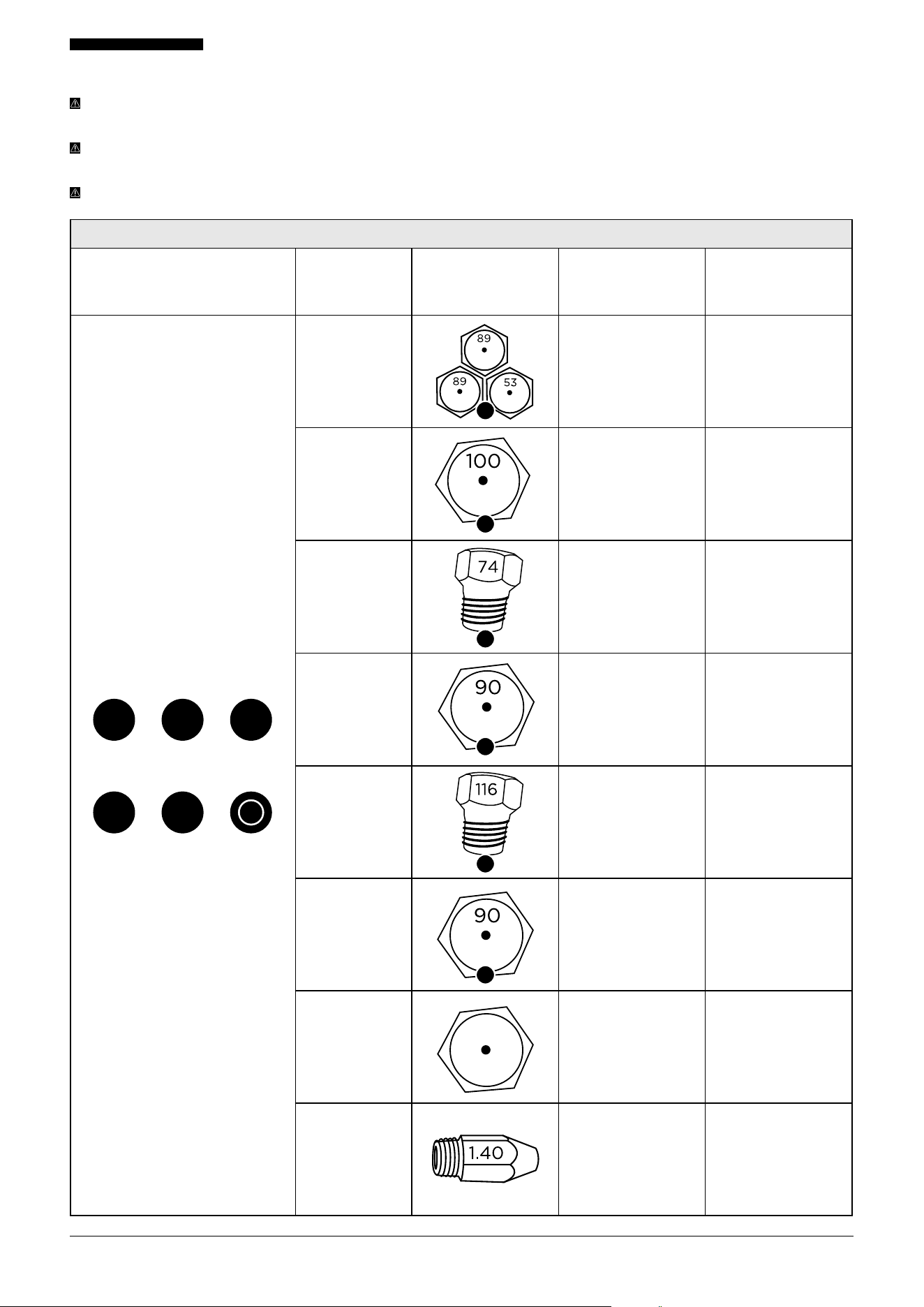
LIQUID PROPANE CONVERSION (CONTINUED) ORIFICE NUMBERS
INSTALLATION TIP: To help prevent any mix-ups during installation, it’s best to remove all existing natural gas (NG)
orifices first, and then install the liquid propane (LPG) orifices.
IMPORTANT: Each orifice has a number indicating its flow diameter printed on the body. You MUST install the correct
orifice in the exact location as noted in the illustrations and the orifice table below for the PRG30 MODEL.
NOTE: For dual burners (A), make sure to replace all three orifices: one in the center and two on the sides.
PRG30 ORIFICES
Burner Layout Burner LPG (Orifices) NG LPG
D B
C A
A 1.36 (2) +0.73 0.89 (2) + 0.53
B 1.36 0.90
C 1.79 1.16
D 1.36 0.90
Oven Broil 1.42 0.94
Oven Bake 2.13 1.40
53
53
53
53
53
A
B
C
D
53
0.94
22001-082525-03 PRG Model USER MANUAL
LIQUID PROPANE CONVERSION (CONTINUED) ORIFICE NUMBERS
INSTALLATION TIP: To help prevent any mix-ups during installation, it’s best to remove all existing natural gas (NG)
orifices first, and then install the liquid propane (LPG) orifices.
IMPORTANT: Each orifice has a number indicating its flow diameter printed on the body. You MUST install the correct
orifice in the exact location as noted in the illustrations and the orifice table below for the PRG36 MODEL.
NOTE: For dual burners (A), make sure to replace all three orifices: one in the center and two on the sides.
PRG36 ORIFICES
Burner Layout Burner LPG (Orifices) NG LPG
F D B
E C A
A 1.36 (2) +0.73 0.89 (2) + 0.53
B 1.57 1.00
C 1.07 0.74
D 1.36 0.90
E 1.79 1.16
F 1.36 0.90
Oven Broil 1.42 0.94
Oven Bake 2.13 1.40
53
53
53
A
E
53
D
53
F
B
C
53
0.94
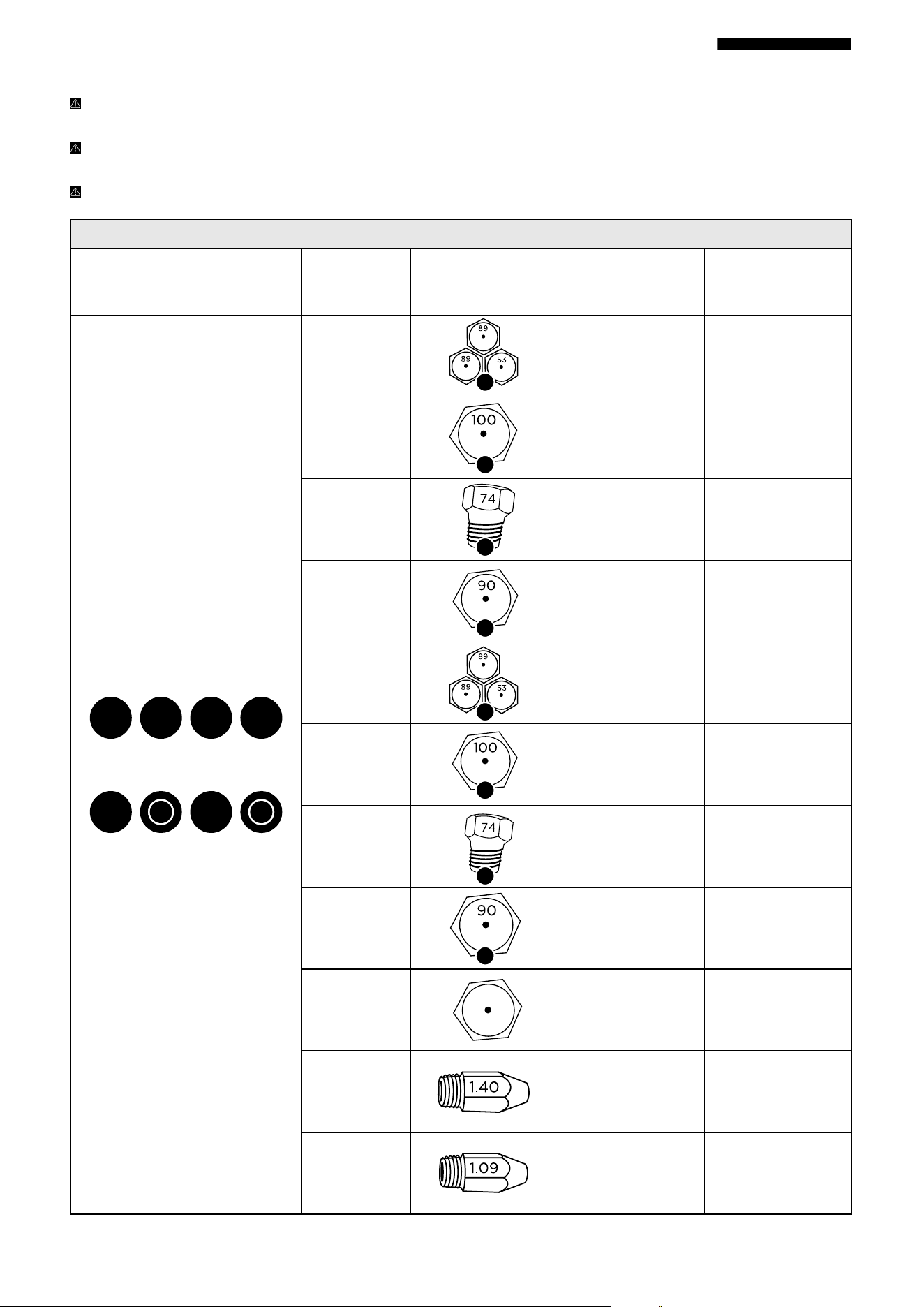
23001-082525-03 PRG Model USER MANUAL
LIQUID PROPANE CONVERSION (CONTINUED) ORIFICE NUMBERS
INSTALLATION TIP: To help prevent any mix-ups during installation, it’s best to remove all existing natural gas (NG)
orifices first, and then install the liquid propane (LPG) orifices.
IMPORTANT: Each orifice has a number indicating its flow diameter printed on the body. You MUST install the correct
orifice in the exact location as noted in the illustrations and the orifice table below for the PRG48 MODEL.
NOTE: For dual burners (A and E), make sure to replace all three orifices: one in the center and two on the sides.
PRG48 ORIFICES
Burner Layout Burner LPG (Orifices) NG LPG
H F D B
G E C A
A 1.36 (2) +0.73 0.89 (2) + 0.53
B 1.57 1.00
C 1.07 0.74
D 1.36 0.90
E 1.36 (2) + 0.73 0.89 (2) + 0.53
F 1.57 1.00
G 1.07 0.74
H 1.36 0.90
Oven Broil 1.42 0.94
Large Oven
Bake
2.13 1.40
Small Oven
Bake
1.68 1.09
53
53
53
A
B
F
C
G
53
D
53
H
53
53
53
E
53
0.94
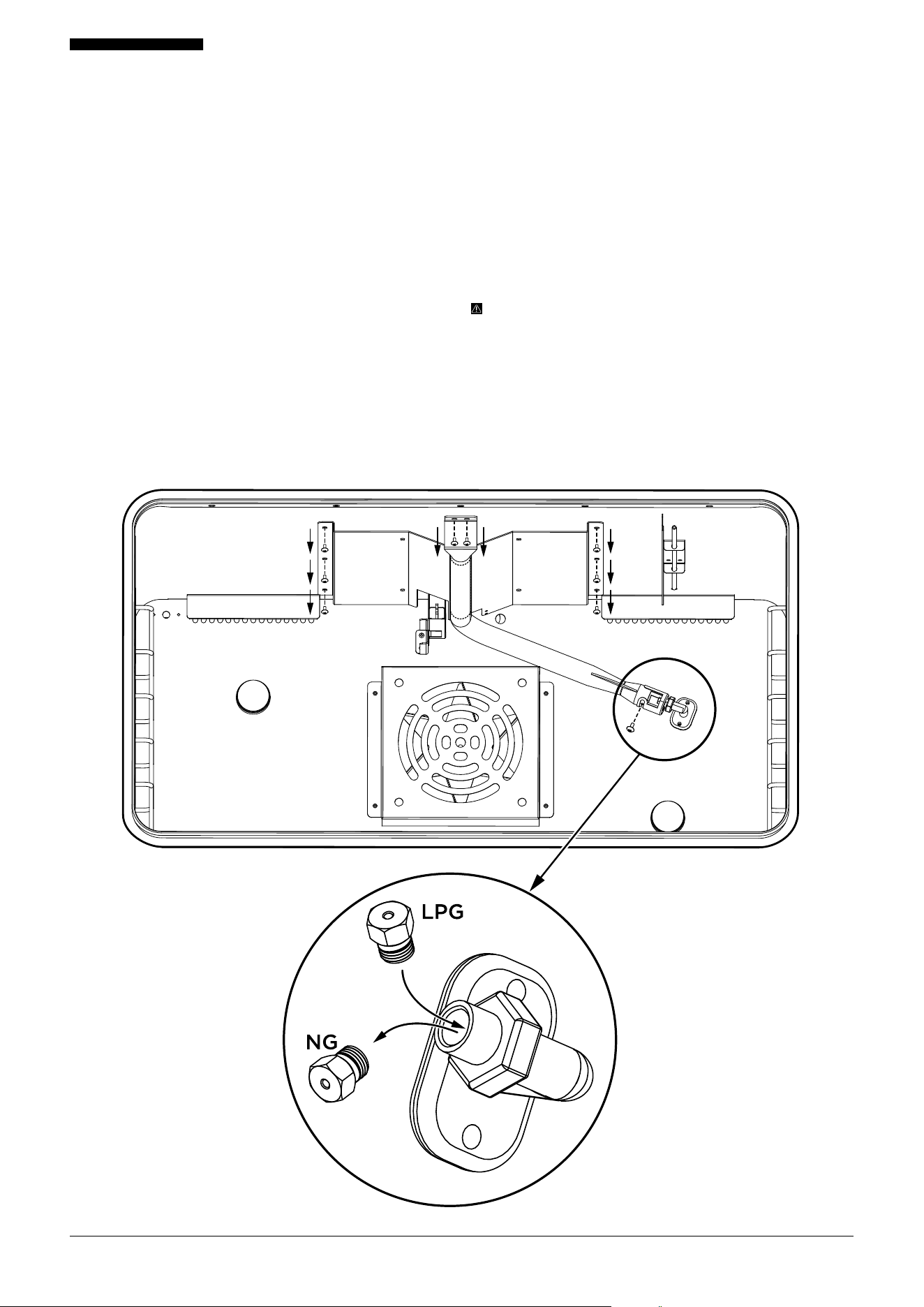
24001-082525-03 PRG Model USER MANUAL
LIQUID PROPANE CONVERSION (CONTINUED)
Changing Upper Oven Orifices: PRG30, PRG36, PRG48
Large Oven
TOOLS NEEDED
• Phillips-head screwdriver or drill bit
• 7 mm socket wrench
1. PREPARE THE OVEN
Open the oven door fully. Remove the oven racks by sliding
them out to full extension, then lifting up and out of the
sliding mechanism. Set racks aside.
Carefully lift up the bottom drip pan from each front corner
and slide it out, taking care not to damage the lower burner
spread. Set drip pan aside.
2. REMOVE BURNER SPREAD
Using a Phillips-head screwdriver or drill bit, remove the 8
screws securing the upper broil burner spread (2 screws at
the front, 3 screws along each side).
Carefully disconnect the burner vent from the back wall of
the oven to access the orifice.
ORIFICE
LOCATION
3. REPLACE THE ORIFICE
Use a 7 mm socket wrench to remove the existing natural
gas orifice. Set aside the natural gas orifice for future use.
Install the liquid propane gas orifice in the exact position.
Carefully screw in the new orifice; do not overtighten.
4. REASSEMBLE BURNER
Reposition the burner vent over the new orifice. Re-secure
the burner spread with the 8 screws removed earlier.
5. REINSTALL OVEN COMPONENTS
Replace the bottom drip pan carefully. Reinstall the oven
racks by sliding them into the guides.
IMPORTANT: Handle parts gently to avoid damaging wires
or components connected to the burner vent. Ensure all
screws and parts are securely reinstalled before operating
the oven.
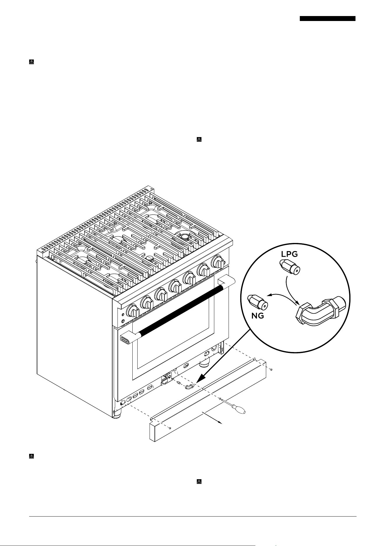
25001-082525-03 PRG Model USER MANUAL
LIQUID PROPANE CONVERSION (CONTINUED)
Changing Lower Oven Orifices: PRG30, PRG36, PRG48
Large and Small Oven
WARNING: Be careful not to scratch or damage the
connection wire that remains connected throughout this
procedure for the lower burner spread.
TOOLS NEEDED
• Phillips-head screwdriver or drill bit
• 10 mm socket wrench
1. REMOVE THE KICK PLATE
Remove the three screws securing the kick plate (one on
each side and one in the center). Lift the kick plate and pull
it out from the side slots.
2. REMOVE THE LOWER BURNER ORIFICE HOLDER
Using a 10 mm socket wrench, remove the orifice holder
along with the natural gas orifice. Access it from the front of
the unit, where it is mounted to the support bracket.
NOTES:
The diagrams provided detail the lower burner
spreads for PRG30 and PRG36 series ranges, and the
larger oven on the PRG48 model.
The PRG48 small oven’s lower burner spread looks slightly
dierent, but the orifice replacement process is the same.
3. REPLACE THE ORIFICE
Use a 10 mm socket wrench to remove the existing natural
gas orifice and set it aside for future use.
Install the liquid propane gas orifice in the same location.
Carefully screw in the new orifice and avoid over-tightening.
4. REASSEMBLE BURNER
Using a 10 mm socket wrench, reposition the orifice holder
onto the support bracket and ensure it is secured in its
original position.
5. REINSTALL THE KICK PLATE
Carefully place the kick plate back into position. Reinstall the
screws to secure the panel and avoid over-tightening.
IMPORTANT: Handle parts gently to avoid damaging wires
or components connected to the burner vent. Ensure all
screws and parts are securely reinstalled before operating
the oven.
The PRG48 small oven does not have an upper broil
burner, so no upper orifice replacement is needed for
liquid propane conversion.
IMPORTANT: After completing the conversion, check all
piping connections for leaks using a soap solution (75%
water, 25% dish soap). Tighten any connections if leaks are
found.
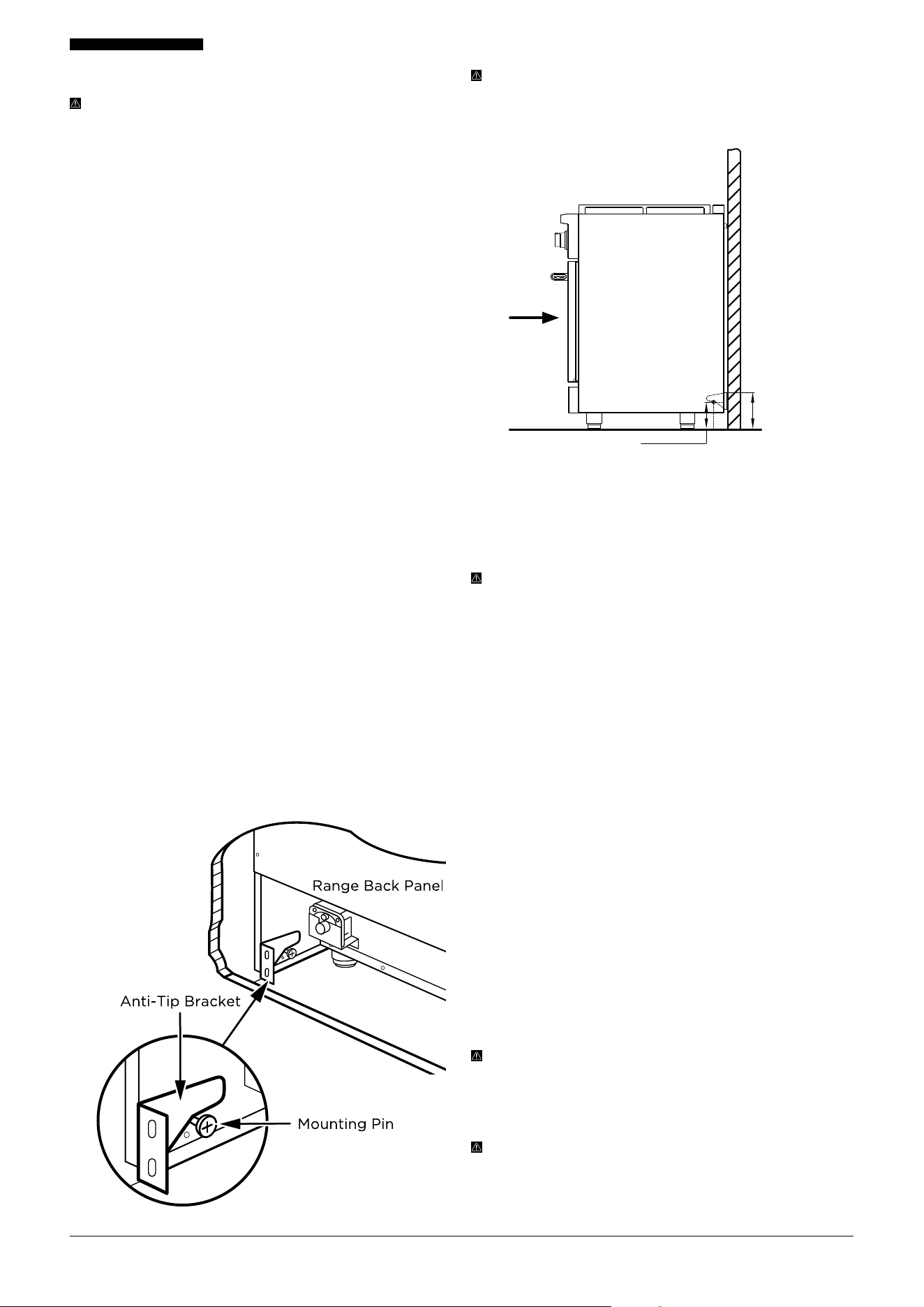
26001-082525-03 PRG Model USER MANUAL
INSTALLING THE ANTI-TIP BRACKET
DANGER: A child or adult can be seriously injured or killed
if the range tips forward. DO NOT operate the appliance
without the anti-tip device in place. Failure to install it
properly can result in death or serious burns.
STEP-BY-STEP INSTALLATION INSTRUCTIONS
1. Position the range in its cabinet space. Adjust the leveling
feet to the desired height. Slide the range forward slightly
to access the back wall.
2. Attach the anti-tip brackets to the wall:
• Drill two holes per bracket
• Secure with the 4 included screws
• The mounting side of the bracket must face the cabinet
• For concrete or tile walls, use the included anchors —
tap them in first with a hammer, then install screws
3. Set bracket height by measuring from the floor to the
bottom of each side panel (see manual diagrams).
• Use a level to ensure both brackets are installed evenly.
4. Install the mounting pins:
• These are included in your anti-tip kit
• Screw one pin into each side of the oven base recess,
left and right
5. Recess width reference by model:
• PRG30: 28 ¼" (718 mm)
• PRG36: 34 ¼" (870 mm)
• PRG48: 46 ⅛" (1172 mm) NOTE: Cabinet dimensions
may vary, so measure carefully before securing the
brackets.
6. Slide the range back into place:
• Slightly tilt the front of the range upward, then push it
gently toward the wall
• Make sure each mounting pin slides under its bracket
WARNING: Gently pull the range from the rear. If the
anti-tip device is correctly installed, the mounting pins will
catch on the brackets, and the range will not tip more than
4" (102 mm) from the wall.
FINISH INSTALLATION
1. Once the gas connection and anti-tip brackets are securely
installed, plug the range’s NEMA 14-50 electrical cord into
a properly grounded 4-prong outlet.
WARNING: The outlet must remain easily accessible after
installation. The power supply cord MUST NOT exceed
122°F (50°C) above room temperature at any point.
2. Slide the range into its final position.
3. Check the anti-tip installation by gently pulling on the
back of the range. It should not tip more than 4" (102
mm).
4. Install the burner spreads by aligning each one so the
white spark tip fits into the hole in the spread.
5. Place the burner caps snugly and level on top of each
spread.
6. Carefully place the grates on the cooktop. Avoid
scratching the burner caps, burner spreads, or porcelain
surface.
7. Use a level to adjust the front and / or rear feet until the
range is flush with your countertop and fully level. A level
appliance helps prevent uneven cooking or baking.
8. After completing all connections:
• Make sure all burner and oven controls are in the "OFF"
position
• Turn on the main gas supply valve
WARNING: It may take a few minutes for gas to flow
freely after connection. You may need to try lighting the
burners or oven a few times. Refer to the User Manual for
flame adjustment and lighting instructions.
NOTE TO INSTALLER: Leave this installation manual with
the homeowner. It should be kept for local inspections,
future reference, and troubleshooting. Refer to the
User Manual for full operation, maintenance, and safety
information.
6 ¼" (160 mm)
4 ½" (115.5 mm)
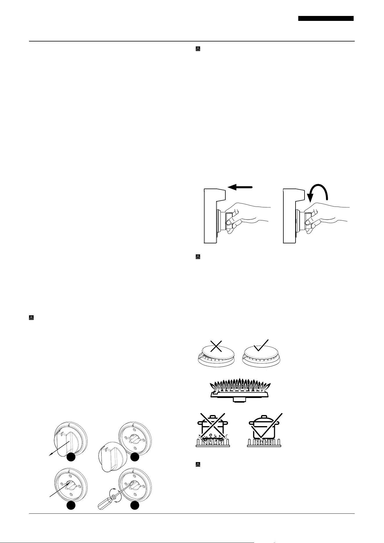
27001-082525-03 PRG Model USER MANUAL
NOTE: The high flame setting cannot be lowered. For
dual burner knobs on all models, two screws may need
adjustment—one for the inner ring and one for the outer
ring. These screws are on the left side of the adjustment
valve.
4. SURFACE BURNER OPERATION
1. To ignite a surface burner, press in the knob for the burner
you want to use—this releases gas (see first image below).
2. Turn the knob counter-clockwise to the “HI” position
(see second image). You’ll hear a spark from the metal
electrode near the white ceramic tip. Wait 0.5 to 2
seconds for the burner to light.
3. Once lit, turn the knob to adjust the flame to your desired
heat level. If the flame goes out and DOES NOT reignite
automatically, turn o the burner and repeat the process.
WARNING: ALWAYS handle the cooktop and oven knobs
with care.
• Turn knobs gently and ON LY as far as needed to reach
the desired setting.
• Avoid turning knobs past their highest setting.
• DO NOT force the knobs in the wrong direction — doing
so may cause permanent damage.
USING THE BURNERS CORRECTLY
1. ALWAYS confirm that
burner caps are installed
correctly before use.
2. The flame on the
cooktop burners should
be fully blue and even, as
shown in the diagram.
3. NEVER let flames rise
up around the sides of
your cookware—this is a
safety risk and can also
damage pots and pans.
WARNING: Burner Cap Positioning
ALWAYS make sure the black burner cap is properly
installed and centered on the burner spread before
igniting. An o-center or missing burner cap can lead to
uneven flames and increase the risk of injury.
1. COOKTOP SAFETY
• ALWAYS turn burner knobs to the "OFF" position before
removing cookware.
• DO NOT lift the cooktop. Doing so may cause damage or
aect the appliance’s performance.
• If the appliance is near a window, DO NOT hang long
curtains that could blow over the burners and catch fire.
• DO NOT operate burners without cookware on the grate.
The heat can damage the grate’s finish without a pan to
absorb it.
2. GUIDELINES FOR USING SURFACE BURNERS
PRG model ranges use electric ignition and include an auto
re-ignition feature. If a flame goes out unexpectedly—such
as from a breeze—the system will detect it and automatically
reignite the burner if gas is still flowing.
When you press one burner knob, you may see sparking at
all burners. This is normal. ON LY the selected burner will
release gas.
Keep burners clean—especially after spills or boil-overs.
Residue can clog the igniter or burner notches and prevent
the burner from lighting or working properly.
Burner flames should be steady and blue. Occasional yellow
tipping is normal, but avoid flames that flicker or spread
unevenly around the burner cap.
3. MANUAL FLAME ADJUSTMENT
Each range includes a manual flame adjustment feature if
burner flames are uneven or appear too yellow or orange.
The range is designed to keep flames at the proper level, but
adjustments can be made if needed.
NOTE: All burner flames are factory-set and tested before
shipping. We recommend contacting Hauslane Customer
Experience before attempting any adjustments.
Follow these steps:
1. Light one burner and set it to the lowest setting. Then,
carefully pull the knob straight o.
2. Inside each burner is an adjustment screw. Using a 2
mm x 50 mm flathead screwdriver, locate the screw (see
diagram—it’s on the right) and turn it left or right until the
flame reaches the desired minimum. Use a flashlight if the
screw is hard to see. Make sure the flame stays lit when
switching from HI to LO.
How to Use Your Range
1
3
2
4
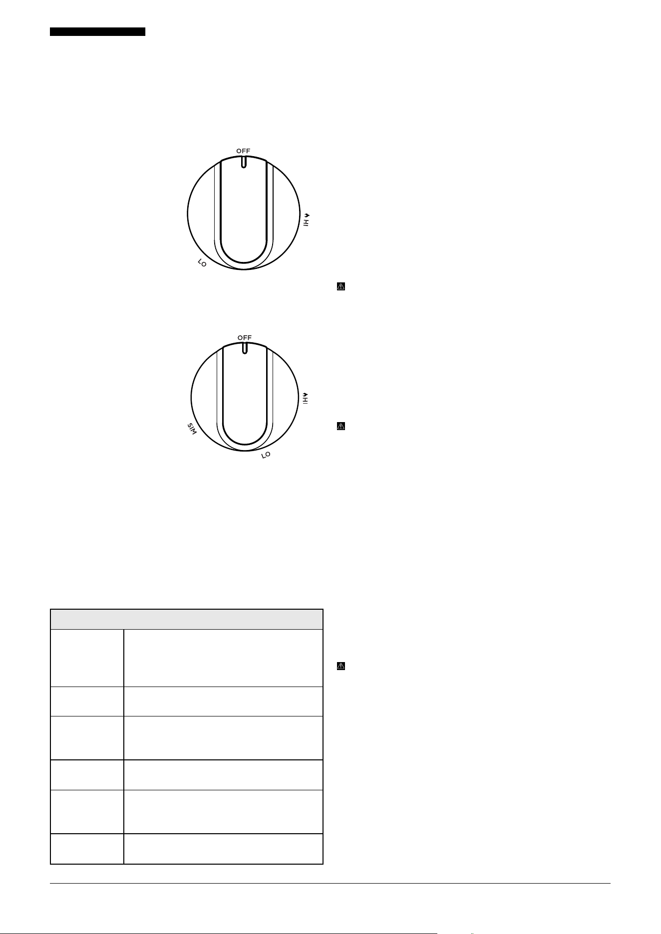
28001-082525-03 PRG Model USER MANUAL
PRG models include special dual burners with a simmer
setting (the PRG48 model features two). Use this setting
for melting chocolate or butter, cooking rice and delicate
sauces, simmering soups and stews, or keeping food warm.
For all other cooking needs, adjust each knob as needed
between the minimum and maximum flame settings, as
shown below:
DUAL RING BURNER KNOB
HI: Maximum Flame Height
LO: Minimum Flame Height
SIM: Simmer Mode
SURFACE BURNER KNOB FUNCTION
SINGLE RING BURNER KNOB
HI: Maximum Flame Height
LO: Minimum Flame Height
SURFACE BURNER FLAME SIZE
When adjusting burner knobs, turn them slowly until you
reach your desired flame size.
Flames should be steady and mostly blue. Some flickering of
orange or yellow is normal.
If flames appear consistently orange or yellow, check for
environmental factors like candles, cleaning products, or
other changes that may aect flame color.
If the issue continues after a liquid propane conversion by
a technician, the conversion may not have been completed
properly. Ensure all orifices are correctly positioned. If
using natural gas, contact your installer or gas company for
assistance.
WARNING: COMBUSTION SAFETY
Gas appliances may emit small amounts of substances
such as benzene, carbon monoxide, formaldehyde, and
soot, mainly due to incomplete combustion of natural gas
or propane.
Properly adjusted burners with clean blue flames help
minimize these emissions.
Ventilate your kitchen by opening windows or using a
ventilation fan or range hood to reduce exposure.
WARNING: When using the cooktop for the first time,
burners may take a moment to ignite as gas fills the
system. DO NOT hold the burner knob pushed in for
longer than a few seconds.
If the burner does not ignite within four seconds, turn the
knob o and wait at least five minutes to let any gas clear
before trying again.
POWER FAILURE
If a burner doesn’t ignite within 4 seconds, turn the knob
o and wait at least 5 minutes to allow gas to clear before
trying again. Refer to the relighting instructions on page 27.
If your power goes out, you can still light the surface burners
manually. Hold a lit match near the burner, turn the knob
counterclockwise to “HI”, and remove the match once the
burner lights. Adjust the flame as needed.
NOTE: The oven will not operate without electricity.
COOKTOP MAINTENANCE
To prevent staining or discoloration, clean the cooktop after
each use. Wipe up acidic or sugary spills once the surface
has cooled.
Your sealed burners are removable and not fixed to the
cooktop. Spills or boil-overs won’t seep underneath but
should still be cleaned after each use.
Always disconnect the appliance and let it cool before
cleaning. For hygiene and safety, the cooktop must be kept
clean at all times.
When using spray cleaners, avoid spraying electrical
components, the thermostat, or the bulb.
HEAT SETTINGS AND SIMPLE COOKING GUIDE
SIM
(Dual Rings
Burners Only)
Gentle Simmering, Melting Chocolate and
Butter, Cooking Rice, Delicate Sauces,
Soups, Stews, and Keeping Food Warm.
(Dual Burners ONLY )
LOW Melting Larger Quantities of Food.
Low-Medium
Low-Temperature Frying, Simmering
Larger Quantities, Heating Milk, Cream
Sauces, Gravies.
Medium
Sautéing, Browning, Braising, Pan-Frying,
Maintaining a Slow Boil.
Medium-Hi
High-Temperature Frying, Pan Boiling,
Maintaining Slow boil on Larger
Quantities.
HI
Boiling Liquids Quickly, Deep Frying. Also
the Ignition Setting.
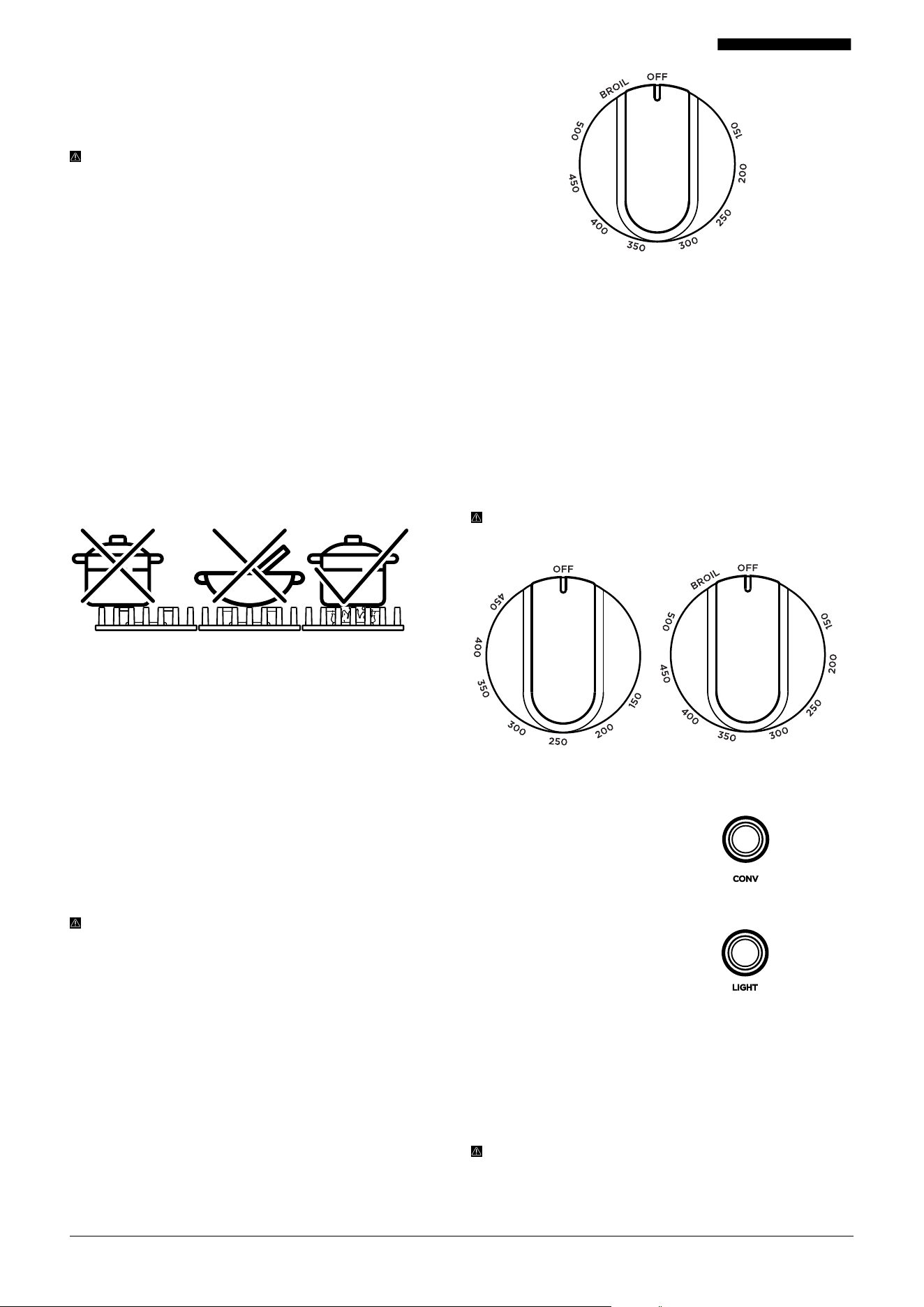
29001-082525-03 PRG Model USER MANUAL
Clean up any food or liquid spills on the cooktop, oven
sides, or oven bottom before cooking to prevent smoke or
fire hazards. For detailed cleaning tips, see the “Care and
Maintenance” section.
WARNING: The U.S. Department of Agriculture advises
not to hold foods between 40 °F and 140 °F (4 °C to 60
°C) for more than 2 hours. Cooking raw foods below 275
°F (135 °C) is not recommended.
BURNER GRATES
Grates must be correctly positioned before use. Misaligned
grates can scratch the cooktop and aect burner
performance.
NEVER operate burners without proper cookware on the
grates.
If using a wok, a wok support ring is required. Wok support
rings are sold separately.
For best results, always center cookware directly on the
grate to ensure even heating and maximum eciency. See
below for more.
GRIDDLE OPERATION (PRG48 RANGE)
Before using for the first time, wash the cast iron griddle
thoroughly with warm, soapy water to remove any dust or
protective coating. Rinse with clean water and dry with a
soft, lint-free cloth.
Place the griddle vertically (front to back) on any of the four
burner grates until it slides into place. DO NOT position the
griddle horizontally (side to side) across multiple grates.
For even heating, turn on both the rear and front burners
beneath the griddle.
WARNING:
The griddle surface can stay hot for several
minutes after use. Allow it to cool completely before
moving or cleaning.
5. OVEN OPERATION
PRG30 AND PRG36 MODELS
To turn on the oven, press in the knob and rotate it counter-
clockwise. When the oven reaches the set temperature, the
white indicator light next to the knob will turn o.
To use the Broil function, turn the knob clockwise to the
Broil setting. The white indicator light will turn on when
active.
PRG30 and PRG36 ranges use one oven knob, with
temperature settings from 150°F to 500°F (65°C to 260°C),
plus a Broil setting.
PRG48 MODELS
The PRG48 range has two oven knobs—one for the small
oven and one for the large oven. The large oven’s maximum
bake temperature is 500°F (260°C), and the small oven’s is
450°F (232°C). Large oven include a "BROIL" setting.
To operate either oven, press in the knob and turn it
counter-clockwise. The blue indicator light next to the knob
will turn o once the oven reaches the set temperature.
To activate the "BROIL" function, turn the knob clockwise to
the Broil setting. The blue indicator light will turn on when
the function is active.
NOTE: The PRG48’s small oven DOES NOT include a broil
feature.
CONVECTION FAN
Push the Convection Fan button to
turn the convection fan On or O.
LIGHT
Push the Light button to turn the
oven lights On or O.
OVEN VENTS
The oven vent is located behind the oven, beneath the back
splash. DO NOT block the vent ducts while the oven is in
use. Maintaining airflow is essential for safe operation.
DO NOT touch the oven vent or nearby surfaces while the
oven is running, as they may become hot and cause burns.
NOTE: It’s normal for steam or moisture to vent and
collect on the cooktop. This is especially common when
baking moist foods or during colder months, when
condensation is more likely due to the temperature
dierence. The water is harmless and non-corrosive.
Oven Knob
Small Oven
Knob
Large Oven
Knob

30001-082525-03 PRG Model USER MANUAL
INTERIOR OVEN SAFETY
WARNING:
NEVER cover any slots, holes, or passages
in the oven bottom, and DO NOT cover entire oven racks
with materials like aluminum foil. Blocking airflow can lead
to poor cooking performance and may increase the risk of
carbon monoxide buildup.
Using aluminum foil in the oven can also trap heat, creating
a fire hazard. Avoid placing aluminum foil on any porcelain
surfaces inside the oven, as it may cause permanent
damage.
Using aluminum foil anywhere on the range may void the
manufacturer’s warranty.
OVEN FUNCTIONS AND FEATURES
BAKE
In Bake mode, heat comes from the bake elements at
the bottom of the oven and circulates naturally. This is a
traditional baking method.
To use Bake, turn on the oven and select a temperature
between 150°F and 500°F (65°C to 260°C). For the PRD48
model, the small oven has a max bake temperature of 450°F
(230°C).
NOTE: Preheating usually takes 12 – 25 minutes,
depending on the desired temperature.
For best results, Hauslane recommends waiting until the
oven is fully preheated before placing food inside.
CONVECTION BAKE
Convection bake uses the bake elements at the bottom of
the oven along with a convection fan in the rear to circulate
hot air evenly. This method allows faster, more even cooking
at lower temperatures.
To activate, turn on the oven, set the temperature, and press
the Convection button located on the oven’s front panel.
NOTE: The PRG48 model’s small oven does not include a
convection fan.
For best convection results, Hauslane recommends allowing
the oven to fully preheat before adding food.
BROIL
When broiling, heat radiates from the top element for fast,
even cooking. Use this function to sear meats or brown the
tops of pre-cooked dishes.
NOTE: Keep the oven door closed during broiling (both
doors for the PRG48 model).
WARNING: ALWAYS keep a close eye on food when using
the broiler. This function heats quickly and can burn food
in just a few minutes if left unattended.
TO ACTIVATE THE BROILER
1. Place food on an oven-safe baking sheet or broiler pan.
2. Position the oven rack at the desired height and place the
pan directly under the broil element. If preheating, wait
until the broiler is hot before placing the pan.
3. Turn the knob clockwise to “BROIL.” The blue indicator
light will turn on.
PREHEATING AND OTHER BROILING TIPS
Preheating is recommended for searing steaks and meats.
Turn the knob to “BROIL” and wait about 2 minutes.
(Preheating is not required when broiling well-done meat.)
ALWAYS remove empty pans from the oven before
preheating to prevent sticking.
The indicator light stays on until the oven reaches
temperature or the knob is turned o.
Fully extend the oven rack to the stop position before
turning or removing food.
For best results, use a broiler pan (not included) with an
insert to drain grease and keep it away from the heat.
The broil setting operates at 500°F (260°C).
WARNING: NEVER use a broiler pan without the insert.
DO NOT cover the broiler pan insert with aluminum foil, as
exposed grease could ignite.
OVEN COOKING
Use caution when opening the oven door(s). Allow hot air or
steam to escape before placing or removing food.
DO NOT heat sealed food containers. Pressure can build and
cause them to burst, resulting in injury.
ALWAYS keep oven vent ducts clear and unobstructed.
OVEN RACK PLACEMENT
Ranges include two commercial-grade telescoping (sliding)
racks, mounted on guides along the oven walls. The PRG48
small oven also includes two telescoping racks.
To install racks, align them between the top and bottom
guides in any of the five rack positions. Pull the rack out
fully, then lift up and out of the sliding mechanism to
remove.
Use caution when handling sliding racks, as edges may be
sharp.
ALWAYS install racks in your desired position before
preheating the oven.
When adjusting racks while the oven is hot, avoid touching
heating elements with potholders or oven mitts.
PRG30, PRG36 and PRG48 large oven racks support at least
25 lb (11 kg). PRG48 small oven racks support at least 15 lb
(7 kg).
WARNING: Use caution when placing heavier food loads
on racks exceeding these weights to avoid risk of injury or
damage to the range.
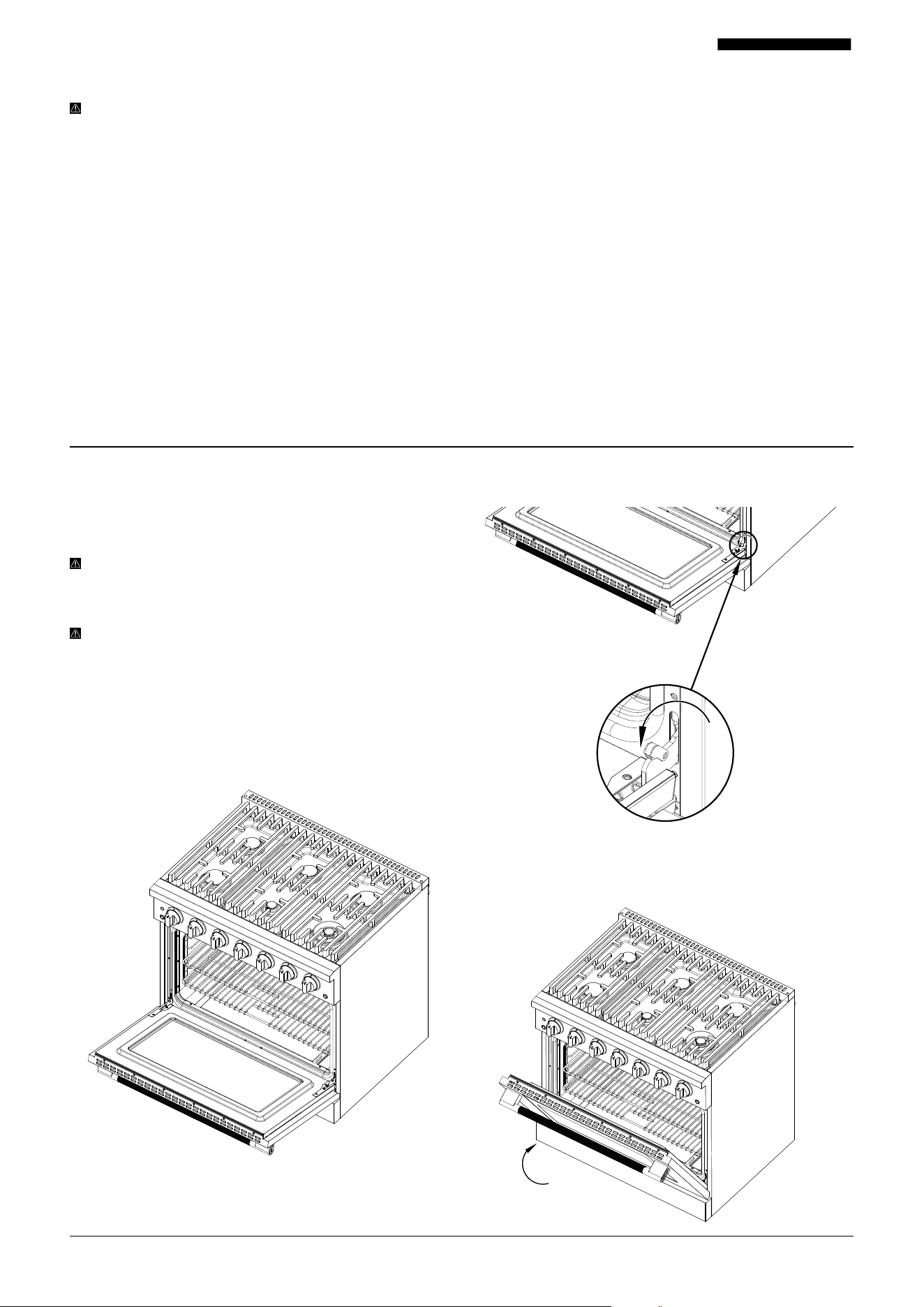
31001-082525-03 PRG Model USER MANUAL
REMOVING THE OVEN DOOR AND KICK PLATE
For everyday use, removing the oven door is not
recommended. ALWAYS ensure the oven is o and
completely cool before reinstalling the door.
NOTE: The steps shown use the PRG36 model as an
example, but the process is the same for PRG30 and
PRG48 models.
WARNING: Be careful when removing and lifting the oven
door — it’s quite heavy. Use a helper if needed. DO NOT
lift the door by the handle, as this may damage the range
and void your warranty.
1. Open the oven door fully.
HEATING ELEMENT AND DOOR SAFETY
WARNING: DO NOT clean the door gasket. The gasket
is crucial for sealing the oven properly. Avoid rubbing,
damaging, or moving it.
Avoid abrasive oven cleaners. NEVER use commercial oven
cleaners or protective liners inside or around the oven. Clean
only the parts specified in the manual. ALWAYS remove
oven racks before cleaning them separately.
DO NOT touch heating elements or the oven interior while in
use or immediately after. Heating elements can be hot even
if they look dark. Oven interior surfaces can cause burns.
If the power goes out, turn all oven and broiler controls to
the OFF position and do not use the oven until power is
restored.
2. Lift and pull back the small levers on both hinges until
they’re fully unlocked.
3. Gently swing the oven door toward the closed position
until the unlocked levers touch the oven frame. The door
should stop about 4" (102 mm) from fully closing.
Basic Maintenance Instructions
During and after use, keep clothing and other flammable
materials away from heating elements and hot oven surfaces
until fully cooled.
Other areas like oven vents, doors, and glass windows may
also get hot enough to cause burns — please be cautious.
ALWAYS double-check that all cooktop, oven, and broiler
controls are turned OFF after cooking.
It’s normal for moisture to appear between the oven door’s
double glass panels, especially when cooking moist foods.
The oven is designed with vents between the glass panes,
and any moisture will usually evaporate within 12 – 24 hours.
When using the oven for the first time, you may notice: An
odor as manufacturing oils burn o — this is normal. Some
noises as new parts settle and adjust during initial heating.
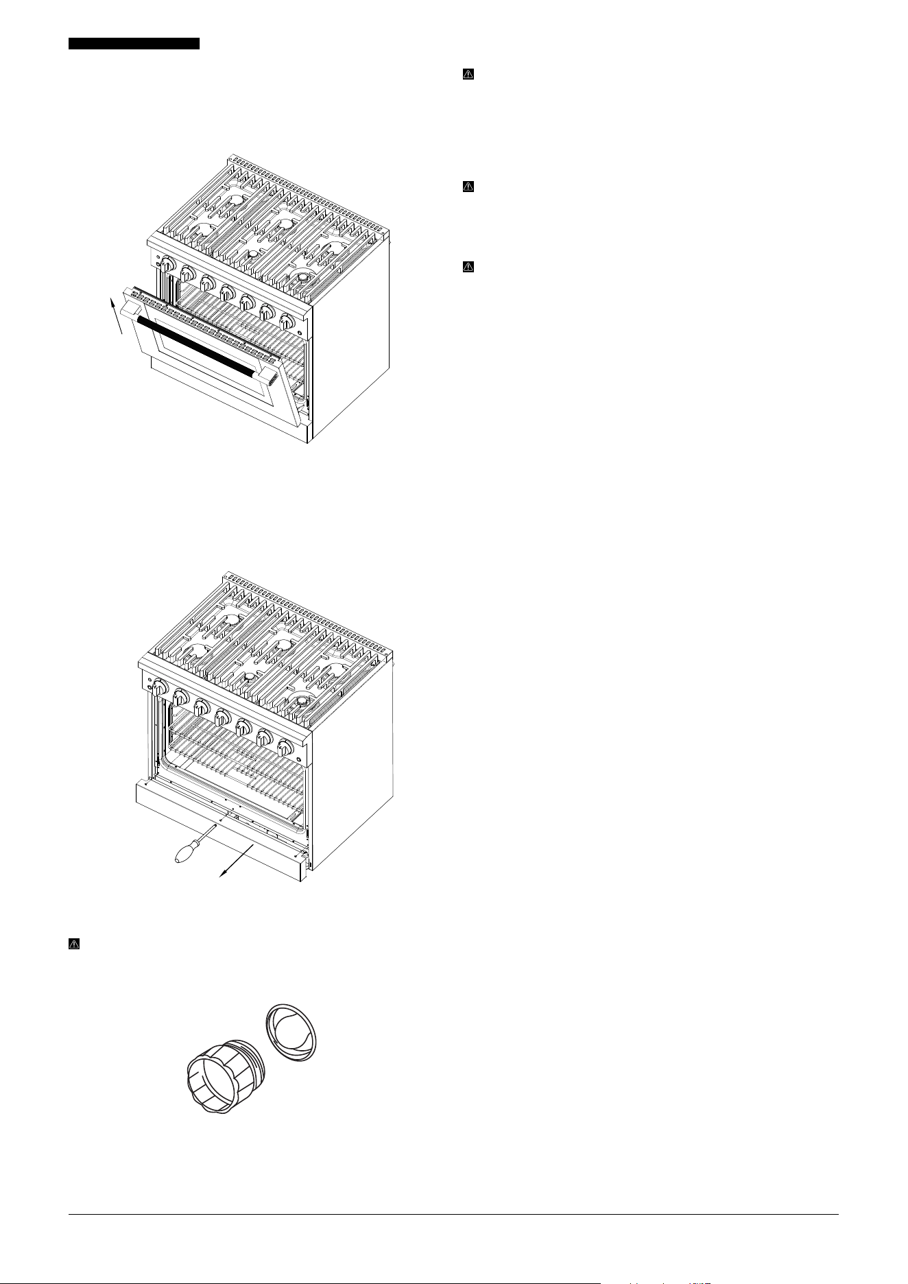
32001-082525-03 PRG Model USER MANUAL
NOTE: Avoid touching the bulbs with your bare fingers
as oils can cause them to burn out prematurely. Use
protective gloves or a clean cloth when handling the
bulbs.
CLEANING YOUR RANGE
WARNING: DO NOT start cleaning until all burners are
o and the oven is completely cool. We also recommend
disconnecting power before cleaning to reduce the risk of
electric shock.
IMPORTANT: NEVER use abrasive cleaners — they can
permanently scratch stainless steel surfaces. Avoid using
bleach or alcohol wipes on stainless steel. ALWAYS follow
the cleaning product’s label instructions.
CONTROL KNOBS
For routine cleaning, wipe knobs with a damp cloth and mild
soap. For greasy buildup, use a nonabrasive liquid detergent
on a damp cloth.
Avoid rotating the knobs during cleaning, as this could
release gas.
To clean stubborn stains, gently pull knobs straight o.
Clean and dry thoroughly, then reinstall on the same valve.
ALWAYS ensure knobs are fully dry before using the range.
BURNER GRATES
ON LY use cast iron grates in their correct positions. DO
NOT operate a burner without cookware on the grate for
extended periods.
Let grates cool completely before cleaning. Use hot water or
white vinegar. DO NOT place grates in the dishwasher.
Ensure grates are securely positioned when reinstalling.
Grates have rubber pads on the feet to prevent scratching
the cooktop. After cleaning, confirm the pads are intact. If
needed, reattach them with heat-resistant adhesive.
ENAMELED CAST IRON GRIDDLE (PRG48 MODEL ONLY)
Let the griddle cool completely, then clean with hot water or
white vinegar. DO NOT place in dishwasher.
Unlike traditional cast iron, this enameled griddle DOES NOT
require regular seasoning (e.g., oiling and baking at high
heat).
BURNER CAPS
Once cool, wash caps in hot, soapy water and rinse well.
To remove stuck-on food, use a plastic scouring pad. Dry
thoroughly before replacing.
DO NOT use stainless steel cleaners on these caps—they are
not made of stainless steel.
BURNER SPREADS
Remove O NLY when fully cool. Wash in hot, soapy water,
rinse, and use a soft brush to clean debris between the slots.
Clean the burner slots regularly with a small wire or needle,
especially after spills that may clog the holes.
Burner spreads and caps are not dishwasher safe.
REPLACING THE OVEN LIGHTS
WARNING: To avoid electrical shock or injury, ensure the
oven and light bulbs are completely cool, and the oven
power is turned o before replacing any bulbs.
The PRG30, PRG36, and PRG48 large ovens each have two
G9 halogen light bulbs located at the upper left and right
corners inside the oven. To replace, unscrew the protective
cap inside the oven that covers the bulb. The PRG48 small
oven has one light bulb.
4. Lift the door up and pull it toward you to release it from
the hinge receivers (see image). It should detach easily. If
not, double-check that the levers are unlocked—DO NOT
force it. To reinstall, reverse steps 1–4.
5. Remove the kick plate by unscrewing the screws, lift up
and pull the kick plate out of the side holes. To reinstall
the kick plate, align it with the holes and reinsert the same
screws.
Don't forget to leave us a review

33001-082525-03 PRG Model USER MANUAL
STAINLESS STEEL
Clean the stainless steel surface with warm sudsy water or
stainless steel polish. Wipe with the grain. ALWAYS follow
product label instructions.
DO NOT use steel wool, harsh cleaners, or anything
containing chlorides or chlorine. These can scratch or
damage the finish.
Wipe away soap with a damp cloth, then dry with a soft,
clean towel.
DOOR HANDLE
Clean with warm soapy water and dry with a soft, lint-free
cloth.
DO NOT use abrasive cleaners or scrubbers, as they can
permanently damage the finish.
OVEN GLASS
Wipe glass surfaces with warm soapy water. For fingerprints
or smudges, use a mild glass cleaner. Dry with a soft, lint-
free cloth.
PORCELAIN SURFACES
Clean the cooktop, oven interior, drip pan, and door liners
with warm soapy water. Rinse and dry with a soft cloth.
Avoid using abrasive powders or liquids. DO NOT leave
acidic or alkaline substances—such as vinegar, lemon juice,
salt, or tomato sauce—on these surfaces.
Use a rubber spatula to gently remove stuck-on food or
residue.
OVEN RACKS
Clean with warm soapy water. For heavier soil, use a non-
abrasive scouring pad like steel wool and plenty of water.
OVEN FRAME
Clean with hot water and soap-filled steel wool pads or
kitchen-safe cleaners. Rinse well and dry.
DO NOT clean the gasket. The fiberglass gasket cannot
tolerate abrasion and must remain intact.
OVEN DOOR
Clean all door surfaces with soapy water. Use glass cleaner
on the exterior glass.
DO NOT use oven cleaners, powders, or abrasives.
Avoid getting water into any door slots or holes, as leftover
soap may cause stains when heated.
WARNING: DO NOT leave acidic fluids such as tomato
sauce or lemon juice on the cooktop or oven interior for
long periods, as this may cause etching and permanent
damage. This type of damage is not covered under the
manufacturer’s warranty.
For the replacement parts list, please visit www.Hauslane.
com or contact us at 1-800-929-0168, or email info@
hauslane.com.
34001-082525-03 PRG Model USER MANUAL
Troubleshooting Tips
WARNING: If a problem cannot be resolved after following the instructions in the manuals, please contact Hauslane at
1-800-929-0168 or email at info@hauslane.com. Never attempt to repair or disassemble gas lines, burner spreads, or the
internal electrical wiring of your range.
PROBLEM POSSIBLE CAUSE SOLUTION
No ignition spark. Ignition module failure
Use manual lighting: hold a lit match near the flame
spreader, push in the control knob, and turn it
counterclockwise to HI. Adjust heat once lit.
Contact customer service if problem persists.
Igniters spark continuously
after flame ignition.
Power supply polarity reversed Contact Hauslane customer service.
Igniters are wet or dirty. Dry or clean igniters thoroughly.
Burners will not light.
Burner parts or igniters wet,
dirty, or misaligned
Check that the burner parts are clean, dry, and
correctly assembled.
Spark tip igniters damaged or
dirty
Check that the igniters are clean and not damaged.
Igniters are sparking
but burners are not
igniting.
Gas shut-o valve is in the
“OFF” position.
Turn shut-o valve to the
“ON” position.
Cooktop burners will not
stay lit and auto reignition
is not working.
Spark tip or igniter failure. Contact Hauslane customer service.
The flames have suddenly
gone out.
A draft or spill has
extinguished the flame.
Turn burners o, clean burners and cooktop area,
then reignite the burners once clean.
Burner flame goes out at
low setting
Low gas pressure. Contact gas company.
Air intake holes around burners
obstructed
Remove obstructions from the air intake holes.
Low flame adjustment may be
set too low.
Readjust the flame setting.
Top burners do not light or
do not burn evenly.
Plug not fully inserted in
electrical outlet
Ensure the unit is properly connected to the power
supply.
Burner holes on burner
clogged
Remove burner heads and clean. Check electrode
area for food or grease buildup and clean thoroughly.
Burner flames are very
large and yellow.
Burner spread ports are
clogged
Clean burner spread ports using a straightened
paperclip, needle, or wire.
Burner spreads or caps not
properly positioned
Remove and carefully reinstall burner spreads and
caps correctly.
Appliance operating with
wrong type of gas
Ensure appliance gas type matches the gas supply.
Regulator missing, faulty, or set
for wrong gas
Have a qualified technician replace or adjust the
regulator appropriately.
35001-082525-03 PRG Model USER MANUAL
Troubleshooting Tips
Still experiencing problems after following these steps?
Contact a technician to assist. Contact us at 1-800-929-0168 or info@hauslane.com.
PROBLEM POSSIBLE CAUSE SOLUTION
Brass burners change color
Brass burners naturally develop a patina
over time. This deep, rich color forms
through oxidation and helps protect the
burners from corrosion. It is a normal
part of the material’s aging process and
does not aect performance. This is not
considered a defect and does not require
return or replacement.
This is a normal occurrence for brass
burners; no troubleshooting is required.
“Cracking” or “popping”
sound is heard coming
from appliance.
Metal heating and cooling sounds
Normal operation noise for ovens; no action
required.
Steam or condensation
from oven vent
Cooking foods high in moisture or cold
ambient temperature
Condensate is natural and non-corrosive; no
action required.
Nothing works (no power) Power supply not energized
Have an electrician inspect power supply,
circuit breaker, wiring, and fuses.
Oven will not heat Oven settings incorrect
Adjust temperature setting or change oven
rack position.
Foods overcooked or
undercooked
Incorrect cooking temperature
Dry or clean igniters; if problem persists,
contact Hauslane customer service.
36001-082525-03 PRG Model USER MANUAL
Extended Warranties
If you are interested in an extended warranty,
sign up on our website at www.hauslane.com
Parts and Accessories
If you need replacement parts or accessories,
visit www.hauslane.com
Contact Us
We’d be happy to answer your questions or
resolve any issues you may have.
Phone: 1-800-929-0168
Email: info@hauslane.com
Find Us and Connect with Us
@HauslaneOcial
Created by Dave Robson
from the Noun Project

HEADQUARTER
222 Harris Ct.
South San Francisco,
CA 94080
United States
E-MAIL
info@hauslane.com
CONTACT US
1-800-929-0168
WEBSITE
www.hauslane.com
SOCIAL MEDIA
@HauslaneOfficial