Models
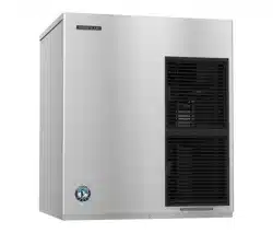
F-1530MAK2(-C)(-SC)
F-1530MWK2(-C)(-SC)
F-1530MRKZ2(-C)(-SC)
F-2030MWK2(-C)
F-2030MRKZ2/3(-C)(-SC)
F-2030MLKZ
Modular Flaker
Instruction Manual
Issued: 6-2-2026
Revised: 8-4-2026
hoshizakiamerica.com
2
WARNING
Only qualied service technicians should install and service the appliance. To obtain
the name and phone number of your local Hoshizaki Certied Service Representative,
visit www.hoshizakiamerica.com. No installation or service should be undertaken
until the technician has thoroughly read this Instruction Manual. No service should
be undertaken until the technician has thoroughly read the service manual available
at www.hoshizakiamerica.com. Likewise, the owner/manager should not proceed to
operate the appliance until the installer has instructed them on its proper operation.
Failure to install, operate, and maintain the appliance in accordance with this manual
will adversely affect safety, performance, component life, and warranty coverage
and may result in costly water damage. Proper installation is the responsibility of the
installer. Product failure or property damage due to improper installation is not covered
under warranty.
Hoshizaki provides this manual primarily to assist qualied service technicians in the
installation, operation, maintenance, and service of the appliance.
Should the reader have any questions or concerns which have not been satisfactorily
addressed, please call, send an e-mail message, or write to the Hoshizaki Technical
Support Department for assistance.
Phone: 1-800-233-1940; (770) 487-2331
E-mail: tech-suppor[email protected]
618 Highway 74 South
Peachtree City, GA 30269
Attn: Hoshizaki Technical Support Department
NOTE: To expedite assistance, all correspondence/communication MUST include the
following information:
• Model Number
• Serial Number
• Complete and detailed explanation of the problem.
3
IMPORTANT
This manual should be read carefully before the appliance is installed and
operated. Read the warnings and guidelines contained in this manual carefully as
they provide essential information for the continued safe use and maintenance of
the appliance. Retain this manual for any further reference that may be necessary.
CONTENTS
Important Safety Information ................................................................................................. 5
I. Specications ...................................................................................................................... 8
A. Electrical and Refrigerant Data ..................................................................................... 8
1. F-1530MAK2(-C)(-SC), F-1530MWK(-C)(-SC) .......................................................... 8
2. F-1530MRKZ2(-C)(-SC) ............................................................................................ 9
3. F-2030MWK2(-C)(-SC) ........................................................................................... 10
4. F-2030MRKZ2(-C)(-SC), F-2030MRKZ3 ................................................................. 10
5. F-2030MLKZ ............................................................................................................11
B. Dimensions/Connections ............................................................................................ 12
1. Air-Cooled Models (MAK2(-C)(-SC)) ........................................................................ 12
2. Water-Cooled Models (MWK2(-C)(-SC)) ................................................................. 13
3. Remote Models (MRKZ2/3(-C)(-SC)) ...................................................................... 14
4. Low Side, Parallel Rack System Models (MLKZ) .................................................... 15
5. Remote Condenser Unit URC-14KZ
(use with F-1530MRKZ2(-C)(-SC)) .......................................................................... 16
6. Remote Condenser Unit URC-26KZ
(use with F-2030MRKZ2/3(-C)(-SC)) ....................................................................... 16
II. Installation Instructions .................................................................................................... 17
A. Location ...................................................................................................................... 17
B. Checks Before Installation ........................................................................................... 17
C. How to Remove Panels ............................................................................................... 18
D. Dispenser Unit/Ice Storage Bin and Icemaker Setup .................................................. 19
E. Electrical Connection .................................................................................................. 20
F. Water Supply and Drain Connections ......................................................................... 22
G. Remote Condenser Unit Installation ........................................................................... 26
1. Location .................................................................................................................. 26
2. Checks Before Installation ....................................................................................... 27
3. Setup ....................................................................................................................... 27
4. Line Set Size and Refrigerant Charge ..................................................................... 28
5. Line Set Installation ................................................................................................. 29
6. Electrical Connection .............................................................................................. 31
7. Stacking Remote Condenser Unit ............................................................................ 32
H. Parallel Rack System Connection ............................................................................... 33
1. Line Set Size and Rack System Requirements ....................................................... 33
2. Line Set Installation ................................................................................................. 34
I. Final Checklist .............................................................................................................. 36
1. Pre-Startup ............................................................................................................... 36
2. Post-Startup ............................................................................................................ 37

4
III. Operating Instructions ..................................................................................................... 38
A. Important Notes About Usage ..................................................................................... 38
B. Startup ........................................................................................................................ 39
1. Bin Control Setting ................................................................................................... 39
2. Appliance Startup and Bin Control Check ............................................................... 42
3. Bin Control 2 (Mechanical Backup) ......................................................................... 44
C. Alarm Safeties ............................................................................................................. 45
IV. Maintenance ................................................................................................................... 46
A. Maintenance Schedule ................................................................................................ 47
B. Cleaning and Sanitizing Instructions ........................................................................... 48
V. Preparing the Appliance for Periods of Non-Use ............................................................. 52
VI. Decommissioning and Disposal ..................................................................................... 54
5
Important Safety Information
Throughout this manual, notices appear to bring your attention to situations which could
result in death, serious injury, damage to the appliance, or damage to property.
WARNING
Indicates a hazardous situation that, if not avoided, could result in
death or serious injury.
NOTICE
Indicates a situation that, if not avoided, could result in damage to
the appliance or property.
IMPORTANT
Indicates important information about the use and care of the
appliance.
• Keep clear of obstruction all ventilation
openings in the appliance enclosure or in
the structure for building-in.
• Do not use electrical appliances inside
the appliance unless they are of the type
recommended by the manufacturer.
• Do not store explosive substances such as
aerosol cans with a ammable propellant
in this appliance or use combustible spray
or place volatile or ammable substances
in or near the appliance. They might catch
re.
• Check that cabling will not be subject
to wear, corrosion, excessive pressure,
vibration, sharp edges, or any other
adverse environmental effects. The check
shall also take into account the effects of
aging or continual vibration from sources
such as compressors or fans.
• Only qualied service technicians should
install and service the appliance.
• No installation, operation, or maintenance
should be undertaken until the technician
has thoroughly read this Instruction
Manual. All safety precautions must be
followed.
• No service should be undertaken until the
technician has thoroughly read the Service
Manual available at
www.hoshizakiamerica.com. All safety
precautions must be followed.
• This appliance to be installed in
accordance with the Safety Standard for
Refrigeration Systems ANSI/ASHRAE 15.
• Follow handling instructions carefully in
compliance with national regulations.
• Do not use mechanical devices or other
means to accelerate the defrosting
process or to clean, other than those
recommended by the manufacturer.
• Servicing shall be done by trained service
personnel with certied competence in
handling refrigerants.
• Dispose of properly in accordance with
federal or local regulations.
• Do not pierce or burn.
• Be aware that refrigerants may not contain
an odor.
• Do not damage the refrigeration circuit.
• Do not place any potential ignition sources
in or near the appliance.
WARNING
6
WARNING continued
The appliance should be destined only to
the use for which it has been expressly
conceived. Any other use should be
considered improper and therefore
dangerous. The manufacturer cannot be
held responsible for injury or damage
resulting from improper, incorrect, and
unreasonable use. Failure to install,
operate, and maintain the appliance
in accordance with this manual will
adversely affect safety, performance,
component life, and warranty coverage
and may result in costly water damage.
To reduce the risk of death, electric
shock, serious injury, or re, follow
basic precautions including the
following:
• This appliance is intended for use at
altitudes up to 7,000 m (22,965 ft).
• Wear appropriate personal protective
equipment (PPE) when servicing the
appliance.
• The appliance must be installed in
accordance with applicable national, state,
and local codes and regulations.
• THE APPLIANCE MUST BE
GROUNDED. Failure to properly ground
the icemaker could result in death or
serious injury.
• The appliance requires an independent
power supply of proper capacity. See the
nameplate for electrical specications.
Failure to use an independent power
supply of proper capacity can result in a
tripped breaker, blown fuse, damage to
existing wiring, or component failure. This
could lead to heat generation or re.
• Electrical connection must be hard-wired
and must meet national, state, and local
electrical code requirements. Failure to
meet these code requirements could result
in death, electric shock, serious injury, re,
or damage.
• Move the power switch to the "OFF"
position and turn off the power supply
before servicing. Lockout/Tagout to
prevent the power supply from being
turned back on inadvertently.
• To reduce the risk of electric shock, do not
touch the power switch or control switch
with damp hands.
• Do not make any alterations to the
appliance. Alterations could result in
electric shock, injury, re, or damage to
the appliance.
• Appliance is heavy. Use care when lifting
or positioning. Work in pairs when needed
to prevent injury or damage.
• The appliance is not intended for use by
persons (including children) with reduced
physical, sensory, or mental capabilities,
or lack of experience and knowledge,
unless they have been given supervision
or instruction concerning use of the
appliance by a person responsible for their
safety.
• Do not splash, pour, or spray water
directly onto or into the appliance. This
might cause short circuit, electric shock,
corrosion, or failure.
• Children should be supervised to ensure
that they do not play with the appliance.
• Do not climb, stand, or hang on the
appliance or allow children or animals to
do so. Serious injury could occur or the
appliance could be damaged.
• Keep the area around the appliance clean.
Dirt, dust, or insects in the appliance could
cause harm to individuals or damage to
the appliance.
7
NOTICE
• Follow the water supply, drain connection,
and maintenance instructions carefully to
reduce the risk of costly water damage.
• In areas where water damage is a
concern, install in a contained area with a
oor drain.
• Install the appliance in a location that stays
above freezing. Normal operating ambient
temperature must be within 45°F to 100°F
(7°C to 38°C).
• Level the ice dispenser/ice storage
bin prior to installing the icemaker.
After icemaker installation, conrm the
icemaker is level. An out-of-level icemaker
could result in improper operation, poor
performance, and/or damage to the
icemaker.
• Do not leave the appliance on during
extended periods of non-use, extended
absences, or in sub-freezing temperatures.
To properly prepare the appliance for
these occasions, follow the instructions in
"V. Preparing the Appliance for Periods of
Non-Use."
• If water collects in the bin and will not
drain, turn off the appliance and close the
water supply line shut-off valve. Call for
service.
• Do not place objects on top of the
appliance.
• The dispenser unit/ice storage bin is for ice
use only. Do not store anything else in the
dispenser unit/ice storage bin.
8
I. Specications
A. Electrical and Refrigerant Data
The nameplate and rating label provide electrical and refrigerant data and Year of
Manufacture (YOM). The nameplate is located on the rear panel and the rating label is on
the inside left wall. For certication marks, see the nameplate.
We reserve the right to make changes in specications and design without prior notice.
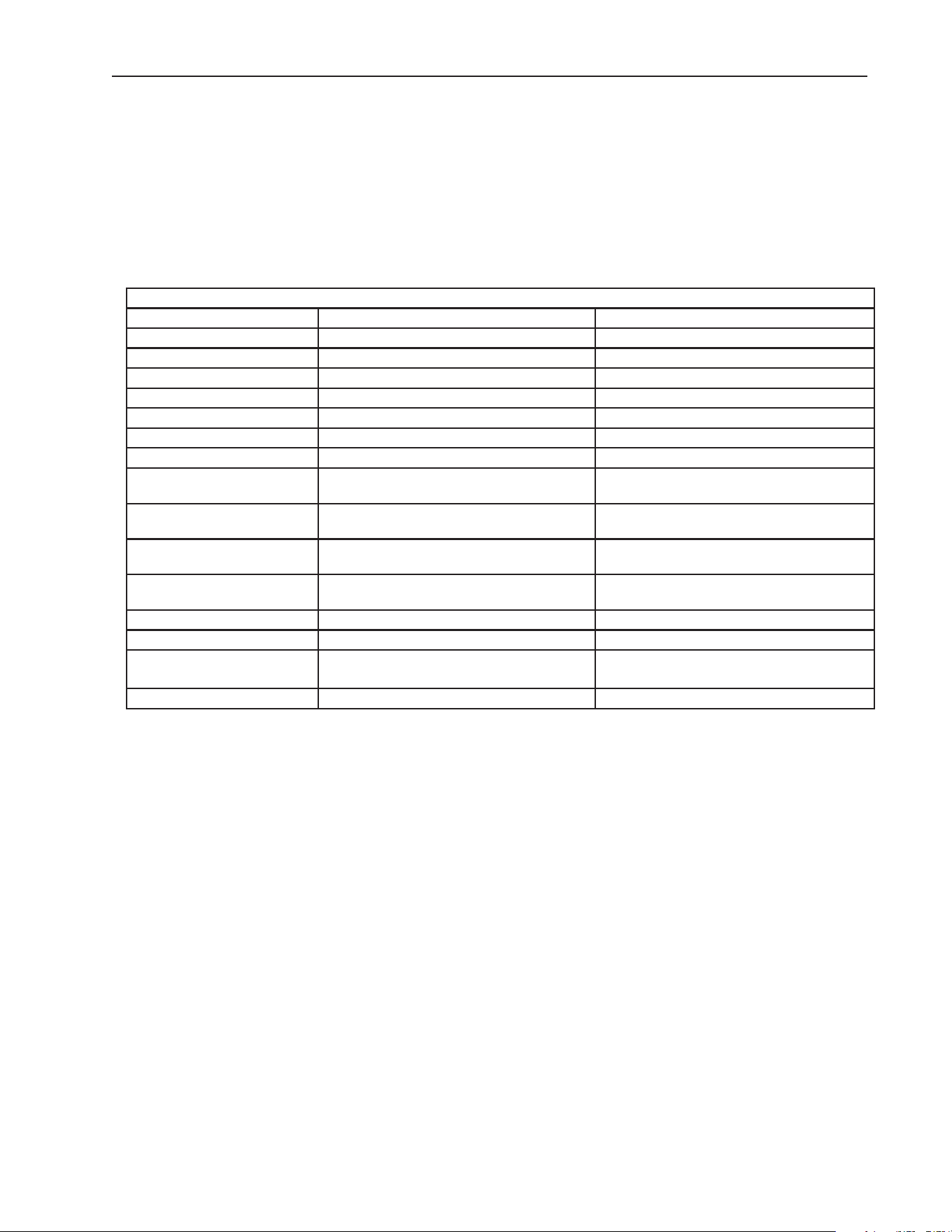
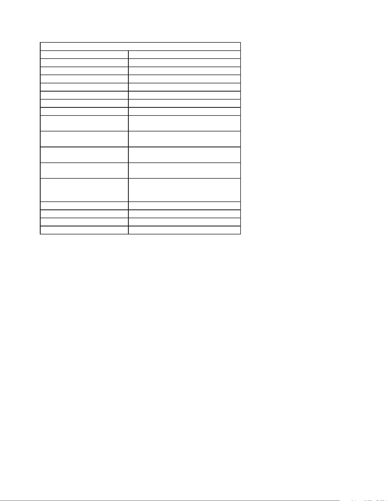
1. F-1530MAK2(-C)(-SC), F-1530MWK(-C)(-SC)
Single Phase
Model Number F-1530MAK2(-C)(-SC) F-1530MWK2(-C)(-SC)
AC SUPPLY VOLTAGE ~208-230/60/1 (3 WIRE W/ NEUTRAL) ~208-230/60/1 (3 WIRE W/ NEUTRAL)
COMPRESSOR 208-230V 9.9RLA 68LRA 208-230V 8.3RLA 56LRA
GEAR MOTOR 115V 5.6 FLA 400W 115V 5.6 FLA 400W
CABINET FAN MOTOR N/A 115V 0.51 FLA 8W
FAN MOTOR 120V 0.9 FLA 1/15HP N/A
OTHER 115V 0.03A 115V 0.03A
MAXIMUM FUSE SIZE 20 AMPS 20 AMPS
MAX. HACR
BREAKER (USA ONLY)
20 AMPS 20 AMPS
MAX. CIRCUIT BREAKER
(CANADA ONLY)
20 AMPS 20 AMPS
MINIMUM CIRCUIT
AMPACITY
20 AMPS 20 AMPS
DESIGN PRESSURE
kpa (PSI)
HI-3220 (467) LO-1724 (250) HI-2650 (385) LO-1960 (285)
REFRIGERANT g (oz.) R-448A 1300 (46) R-448A 500 (17.6)
CLIMATIC CLASS 5 5
INSULATION BLOWING
GAS
HFO 1233zd(E) HFO 1233zd(E)
HARVEST RATE >1,200 LB/DAY (CONTINUOUS) >1,200 LB/DAY (CONTINUOUS)
9
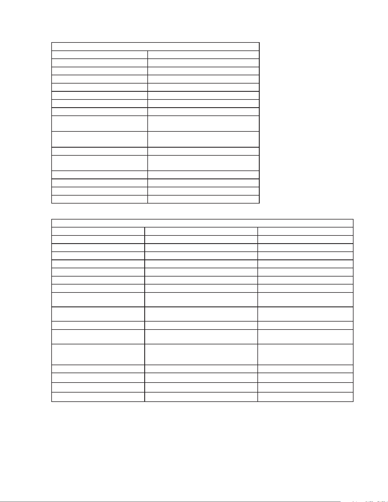
2. F-1530MRKZ2(-C)(-SC)
Single Phase
MODEL NUMBER F-1530MRKZ2(-C)(-SC)
AC SUPPLY VOLTAGE ~208-230/60/1 (3 WIRE W/ NEUTRAL)
COMPRESSOR 208-230V 9.3RLA 56LRA
GEAR MOTOR 115V 5.6 FLA 400W
FAN MOTOR 115V 3A MAX
CABINET FAN MOTOR 115V 0.51FLA 8W
OTHER 115V 0.03A
MAXIMUM FUSE SIZE 20 AMPS
MAX. HACR
BREAKER (USA ONLY)
20 AMPS
MAX. CIRCUIT BREAKER
(CANADA ONLY)
20 AMPS
MINIMUM CIRCUIT
AMPACITY
20 AMPS
DESIGN PRESSURE
kPa (PSI)
HI-3220 (467) LO-1724 (250)
REFRIGERANT g (oz.) R-448A If USED WITH HOSHIZAKI
CONDENSER
URC-14KZ: 5650 (200)
HOSHIZAKI CONDENSER URC-14KZ
CLIMATIC CLASS 5
INSULATION BLOWING GAS HFO 1233zd(E)
HARVEST RATE >1,200 LB/DAY (CONTINUOUS)
10
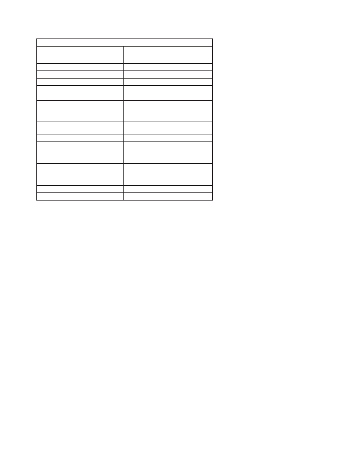
3. F-2030MWK2(-C)(-SC)
Single Phase
MODEL NUMBER F-2030MWK2(-C)
AC SUPPLY VOLTAGE ~208-230/60/1(3 WIRE W/ NEUTRAL)
COMPRESSOR 208-230V 11.5RLA 88LRA
GEAR MOTOR 115V 5.6FLA 400W
FAN MOTOR – – –
CABINET FAN MOTOR 115V 0.51FLA 8W
OTHER 115V 0.03A
MAXIMUM FUSE SIZE 20 AMPS
MAX. HACR BREAKER
(USA ONLY)
20 AMPS
MAX. CIRCUIT BREAKER
(CANADA ONLY)
20 AMPS
MINIMUM CIRCUIT AMPACITY 20 AMPS
DESIGN PRESSURE
kPa (PSI)
HI-2945 (427) LO-1724 (250)
REFRIGERANT g (oz.) R-448A 850 (30)
CLIMATIC CLASS 5
INSULATION BLOWING GAS HFO 1233zd(E)
HARVEST RATE >1,200 LB/DAY (CONTINUOUS)
4. F-2030MRKZ2(-C)(-SC), F-2030MRKZ3
Single Phase
MODEL NUMBER F-2030MRKZ2(-C)(-SC) F-2030MRKZ3
AC SUPPLY VOLTAGE ~208-230/60/1 (3 WIRE W/ NEUTRAL) ~208-230-/60/3
COMPRESSOR 208-230V 13.1RLA 88LRA 208-230V 7.1RLA 88LRA
GEAR MOTOR 115V 5.6FLA 400W 115V 5.6FLA 400W
REMOTE FAN MOTOR 115V 3A MAX 115V 3A MAX
CABINET FAN MOTOR 115V 0.51FLA 8W 115V 0.51FLA 8W
OTHER 115V 0.03A 115V 0.03A
MAXIMUM FUSE SIZE 30 AMPS 20 AMPS
MAX. HACR
BREAKER (USA ONLY)
30 AMPS 20 AMPS
MAX. CIRCUIT BREAKER
(CANADA ONLY)
30 AMPS 20 AMPS
MINIMUM CIRCUIT AMPACITY 30 AMPS 20 AMPS
DESIGN PRESSURE
kPa (PSI)
HI-3220 (467) LO-1724 (250) HI-3220 (467) LO-1724 (250)
REFRIGERANT g (oz.) R-448A If USED WITH HOSHIZAKI
CONDENSER
URC-22KZ: 10,400 (367)
R-448A If USED WITH
HOSHIZAKI CONDENSER
URC-22KZ: 10,400 (367)
HOSHIZAKI CONDENSER URC-26KZ URC-26KZ
CLIMATIC CLASS 5 5
INSULATION BLOWING GAS HF0 1233zd(E) HF0 1233zd(E)
HARVEST RATE >1200 LB/DAY (CONTINUOUS) >1200 LB/DAY (CONTINUOUS)
11
5. F-2030MLKZ
Low-Side Rack System Single Phase
MODEL NUMBER F-2030MLK
AC SUPPLY VOLTAGE ~115/60/1
COMPRESSOR – – –
GEAR MOTOR 120V 5.6FLA 400W
FAN MOTOR – – –
CABINET FAN MOTOR 115V 0.51FLA 8W
OTHER 120V 0.03A
MAXIMUM FUSE SIZE 15 AMPS
MAX. HACR
BREAKER (USA ONLY)
15 AMPS
MAX. CIRCUIT BREAKER
(CANADA ONLY)
15 AMPS
MINIMUM CIRCUIT AMPACITY 15 AMPS
DESIGN PRESSURE
kPa (PSI)
HI-3220 (467) LO-1724 (250)
REFRIGERANT Use only with 448
FACTORY NITROGEN
HOLDING CHARGE kPa (PSI)
103 (15)
CLIMATIC CLASS 5
INSULATION BLOWING GAS HF0 1233zd(E)
HARVEST RATE >1200 LB/DAY (CONTINUOUS)
Note: Climatic Class 5: This appliance electrical safety tested for operation in maximum
ambient temperature of 104°F (40°C) with 40% relative humidity. However,
normal operating ambient temperature must be within 45°F to 100°F (7°C to
38°C); Normal operating water temperature must be within 45°F to 90°F (7°C to
32°C). Operation of the appliance, for extended periods, outside of these normal
temperature ranges may affect appliance performance.
12
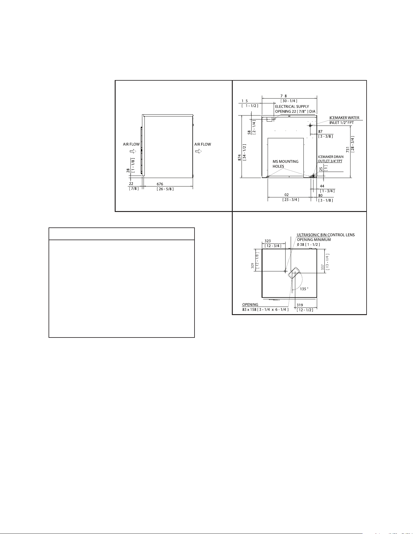
Side
Rear
Bottom
B. Dimensions/Connections
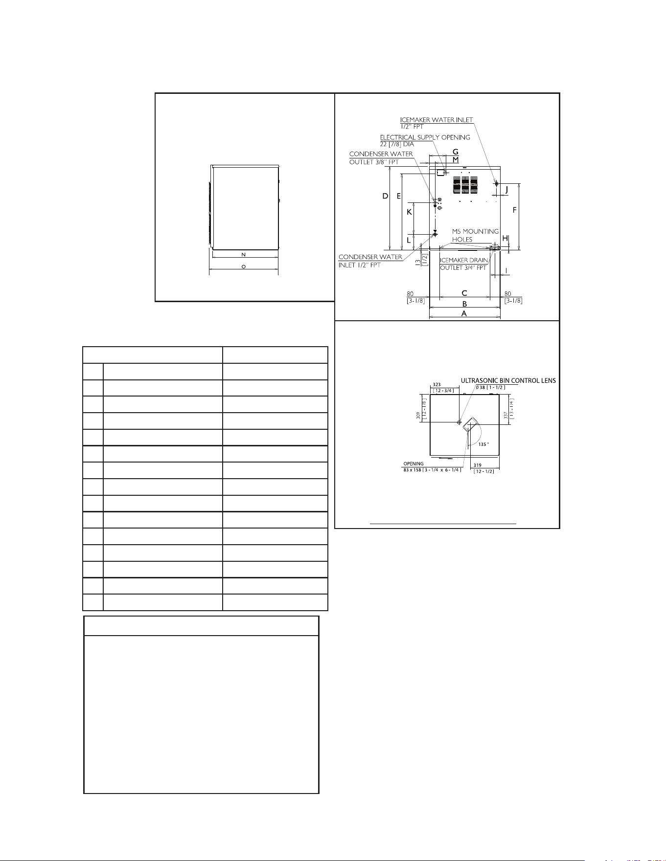
1. Air-Cooled Models (MAK2(-C)(-SC))
Units: mm [in.]
NOTICE
• Allow 6" (15-cm) clearance at rear
and sides for proper air circulation
and ease of maintenance and/or
service should they be required.
Allow 24" (61-cm) clearance at top
to allow for removal of the auger.
• The dispenser unit/ice storage
bin opening must accommodate
the bottom opening as in the
illustration.
13
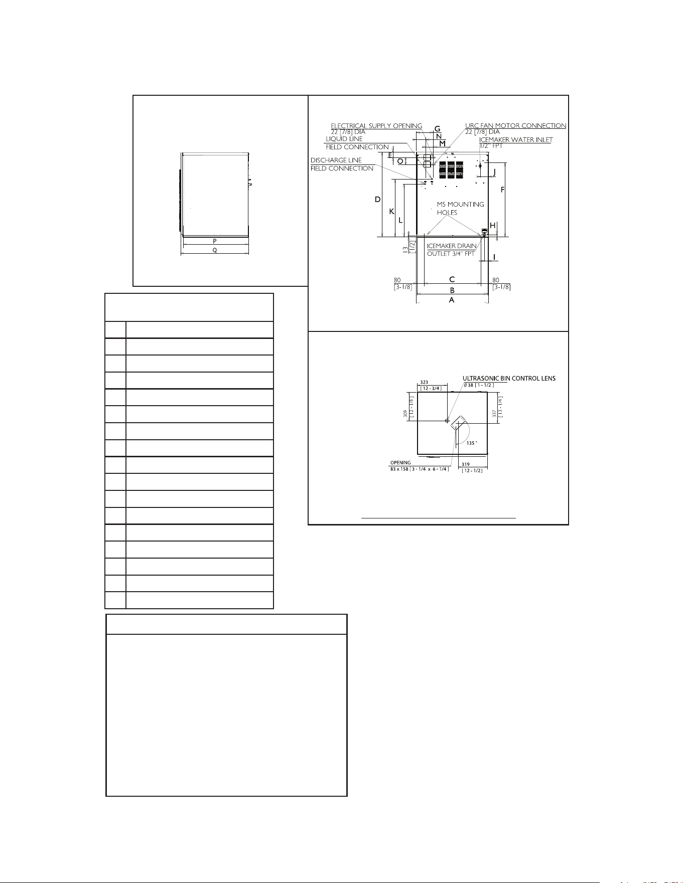
2. Water-Cooled Models (MWK2(-C)(-SC))
F-1530MWK2(-C)(-SC) F-2030MWK2(-C)
A 768 [30-1/4] 768 [30-1/4]
B 762 [30] 762 [30]
C 602 [23-3/4] 602 [23-3/4]
D 874 [34-3/8] 874 [34-3/8]
E 816 [32-1/8] 816 [32-1/8]
F 731 [28-3/4] 705 [27-3/4]
G 165 [6-1/2] 165 [6-1/2]
H 25 [1] 25 [1]
I 43 [1-3/4] 43 [1-3/4]
J 87 [3-3/8] 77 [3]
K 510 [20-1/8] 508 [20]
L 139 [5-1/2] 178 [7]
M 127 [5] 51 [2]
N 676 [26-5/8] 676 [26-5/8]
O 698 [27-1/4] 698 [27-1/4]
NOTICE
• Allow 6" (15-cm) clearance at rear
and sides for proper air circulation
and ease of maintenance and/or
service should they be required.
Allow 24" (61-cm) clearance at top
to allow for removal of the auger.
• The dispenser unit/ice storage
bin opening must accommodate
the bottom opening as in the
illustration.
Side
Rear
Bottom
Model Shown: F-2030MWK2
Units: mm [in.]
14
Side
Rear
Bottom
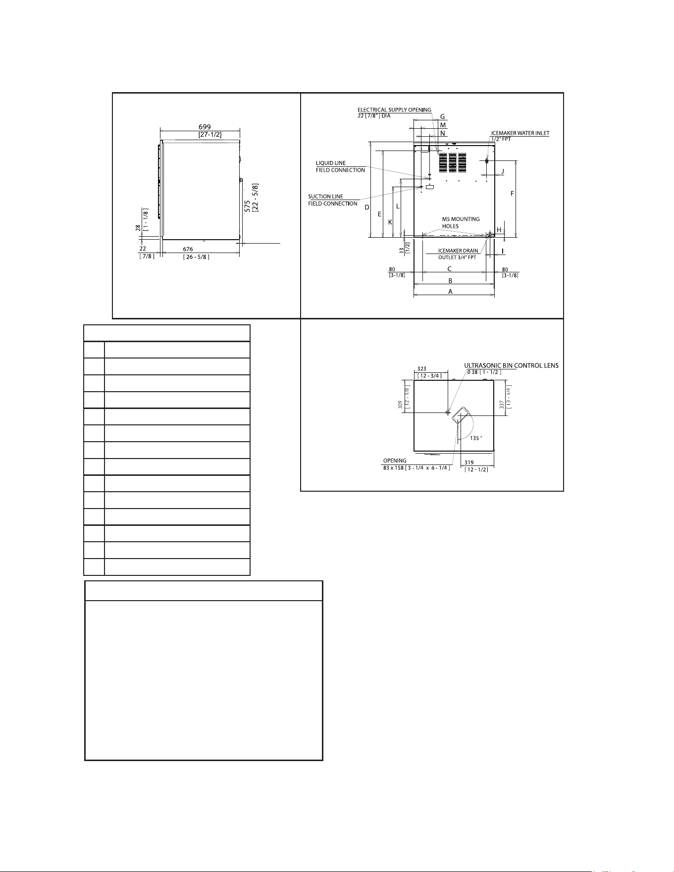
Model Shown: F-1530MRKZ2
3. Remote Models (MRKZ2/3(-C)(-SC))
F-1530MRKZ2(-C)(-SC)
F-2030MRKZ2/3(-C)(-SC)
A 768 [30-1/4]
B 756 [29-3/4]
C 602 [23-3/4]
D 874 [34-3/8]
E 58 [2-1/4]
F 731 [28-13/16]
G 165 [6-1/2]
H 25 [1]
I 44 [1-3/4]
J 87 [3-7/16]
K 594.9
L 542.2 [21-3/8]
M 70.6 [2-3/4]
N 93.6 [3-5/8]
O 70.6 [2-3/4]
P 676 [26-5/8]
Q 699 [27-1/2]
NOTICE
• Allow 6" (15 cm) clearance at rear
and sides for proper air circulation
and ease of maintenance and/or
service should they be required.
Allow 24" (61 cm) clearance at top
to allow for removal of the auger.
• The dispenser unit/ice storage
bin opening must accommodate
the bottom opening as in the
illustration.
Units: mm [in.]
15
34
[1 - 3/8 ]
Side
Rear
Bottom
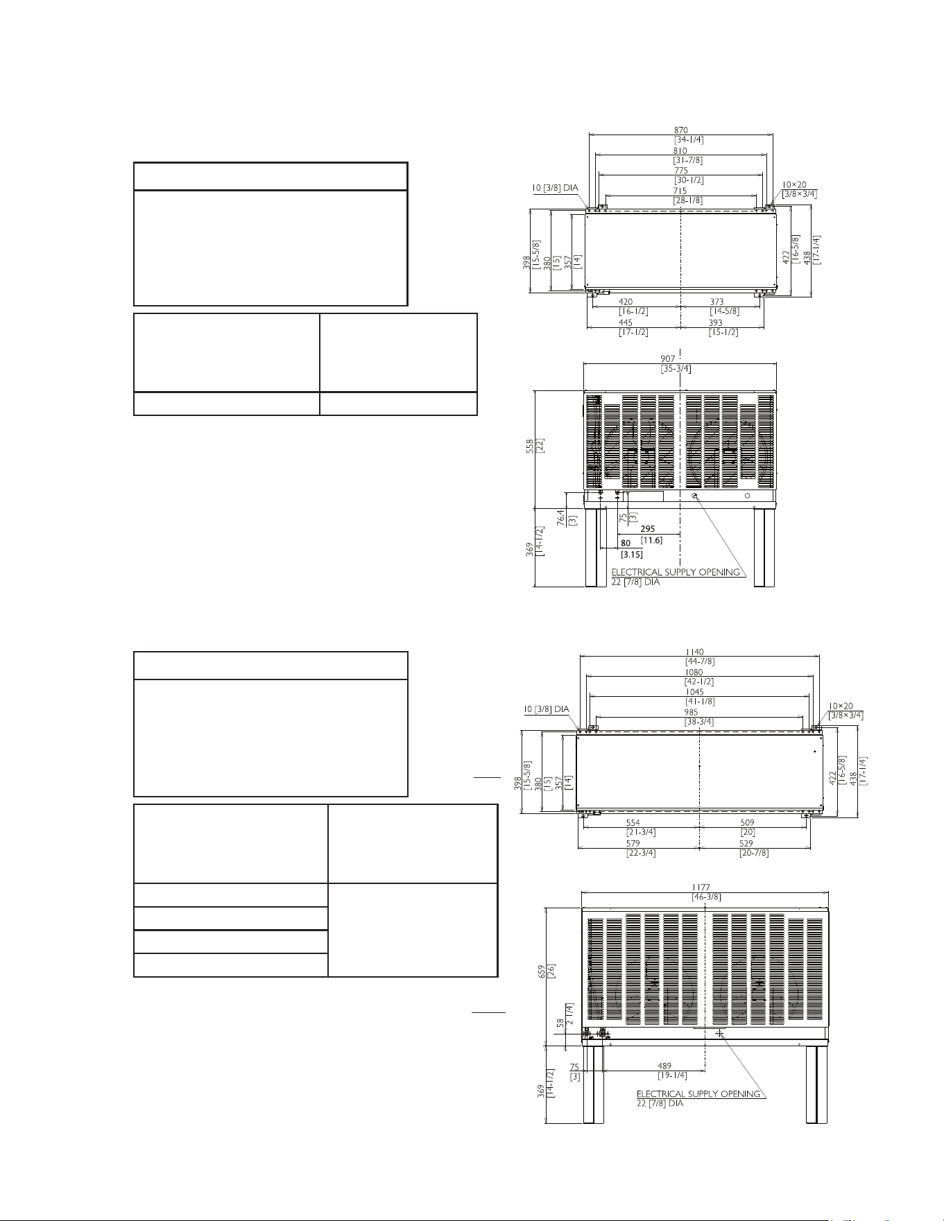
4. Low Side, Parallel Rack System Models (MLKZ)
F-2030MLKZ
A 768 [30-1/4]
B 762 [30]
C 602 [23-11/16]
D 874 [34-7/16]
E 817 [32-3/16]
F 705 [27-3/4]
G 165 [6-1/2]
H 24 [15/16]
I 43 [1-11/16]
J 80 [3-1/8]
K 466 [18-38]
L 519 [22-1/4]
M 71 [2-1/4]
N 79 [3-1/8]
NOTICE
• Allow 6" (15-cm) clearance at rear
and sides for proper air circulation
and ease of maintenance and/or
service should they be required.
Allow 24" (61-cm) clearance at top
to allow for removal of the auger.
• The dispenser unit/ice storage
bin opening must accommodate
the bottom opening as in the
illustration.
Units: mm [in.]
16
6. Remote Condenser Unit URC-26KZ
(use with F-2030MRKZ2/3(-C)(-SC))
NOTICE
Allow 24" (61-cm) clearance
at front and rear for proper
air circulation and ease of
maintenance and/or service
should they be required.
Icemaker Model
URC-26FZ Heat of
Rejection
AT 90°F (32°C)
WT 70°F (21°C)
F-2030MRKZ2 15,000
F-2030MRKZ2-C
F-2030MRKZ2-SC
F-2030MRKZ3
Top
Units: mm [in.]
Units: mm [in.]
5. Remote Condenser Unit URC-14KZ
(use with F-1530MRKZ2(-C)(-SC))
NOTICE
Allow 24" (61 cm) clearance
at front and rear for proper
air circulation and ease of
maintenance and/or service
should they be required.
Icemaker Model
URC-14KZ Heat of
Rejection
AT 90°F (32°C)
WT 70°F (21°C)
F-1530MRKZ2(-C)(-SC) 11,500
Rear
Rear
Top
17
II. Installation Instructions
WARNING
• The appliance must be installed in accordance with applicable national, state, and
local codes and regulations.
• Failure to install, operate, and maintain the appliance in accordance with this
manual will adversely affect safety, performance, component life, and warranty
coverage and may result in costly water damage.
• CHOKING HAZARD: Ensure all components, fasteners, and thumbscrews
are securely in place after installation. Make sure that none have fallen into the
dispenser unit/ice storage bin.
A. Location
NOTICE
• The icemaker is not intended for outdoor use. Normal operating ambient
temperature must be within 45°F to 100°F (7°C to 38°C); Normal operating water
temperature must be within 45°F to 90°F (7°C to 32°C). Operation of the icemaker,
for extended periods, outside of these normal temperature ranges may affect
icemaker performance.
• The icemaker will not work at sub-freezing temperatures. To prevent damage
to the water supply line, drain the icemaker if the air temperature is going to go
below 32°F (0°C). See "V. Preparing the Appliance for Periods of Non-Use."
• The icemaker should not be located next to ovens, grills, or other high heat producing
equipment.
• Allow 6" (15 cm) clearance at rear and sides for proper air circulation and ease of
maintenance and/or service should they be required. Allow 24" (61 cm) clearance at top
to allow for removal of the auger.
• The location should provide a rm and level foundation for the appliance.
B. Checks Before Installation
• Visually inspect the exterior of the shipping container and immediately report any
damage to the carrier. Upon opening the container, any concealed damage should also
be immediately reported to the carrier.
• Remove the shipping carton, tape, and packing material. If any are left in the appliance,
it will not work properly.
• See the nameplate on the rear panel, and check that your voltage supplied corresponds
with the voltage specied on the nameplate.
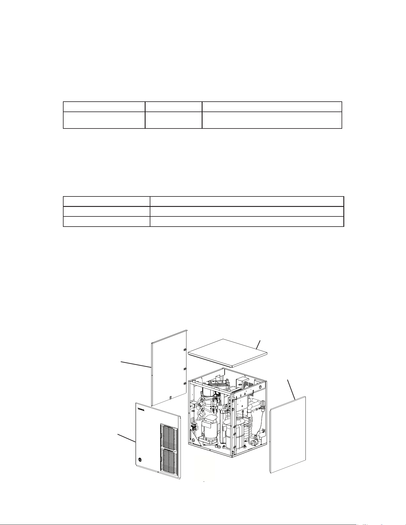
• Remove the panels to prevent damage when installing the appliance. See "II.C. How to
Remove Panels."
• Remove the package containing the accessories.
• Remove the protective plastic lm from the panels. If the appliance is exposed to the
sun or to heat, remove the lm after the appliance cools.
18
Left Side
Panel
Front Panel
Fig. 1
Top Panel
Right Side
Panel
Model Shown: F-1530MWK2
• Check that the refrigerant lines do not rub or touch lines or other surfaces, and that the
fan blade (if applicable) turns freely.
• Check that the compressor is snug on all mounting pads.
• Flaker and soft cubelet (-SC) models can be installed on an ice storage bin only.
Cubelet (-C) models can be installed on either a cubelet-compatible dispenser unit or
an ice storage bin. The ice storage bins listed below are recommended.
Model Number Bin Width Recommended Hoshizaki Ice Storage Bin
F-1530M_K(Z)2(-C)(-SC)
F-2030M_K(Z)2/3(-C)
30" or Wider BD Series
For further options, contact your local Hoshizaki distributor.
• NOTICE! Remote models must be connected to an appropriate remote condenser
unit. The remote condenser units listed below are recommended. Connection to a
different remote condenser unit will void the warranty unless Hoshizaki approves
a different remote condenser unit for your specic application. For further
details, contact your local Hoshizaki distributor.
Model Number Recommended Hoshizaki Remote Condenser Unit
F-1530MRKZ2(-C)(-SC) URC-14KZ
F-2030MRKZ2/3(-C)(-SC) URC-26KZ
• On low-side models, an R-448A parallel rack system is needed. See "II.H. Parallel Rack
System Connection" for refrigeration circuit details.
C. How to Remove Panels
See Fig. 1
• Front Panel: Remove the screw. Lift up and towards you.
• Top Panel: Lift up at front slightly, push rearward and lift off.
• Side Panels: Remove the screw. Slide forward slightly and lift off.
19
Bolts
Fig. 2a
Self-Tapping
Screws
(Not Provided)
Icemaker
Dispenser
Unit
Icemaker
Ice
Storage
Bin
Mounting
Brackets
Bolts
D. Dispenser Unit/Ice Storage Bin and Icemaker Setup
WARNING
The installer must ensure the dispenser unit/ice storage bin is compatible with
the icemaker, and the dispenser unit/ice storage bin and icemaker are properly
attached and secured.
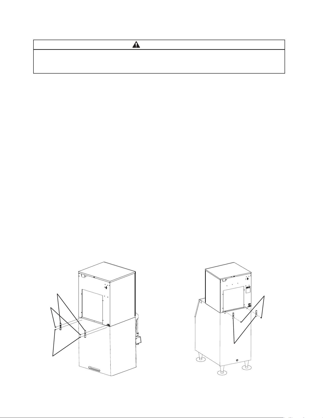
1a) Dispenser Unit: Follow the dispenser unit’s setup procedure. Note that only cubelet
models can be installed on a cubelet-compatible dispenser unit; aker and soft cubelet
(-SC) models cannot be installed on a dispenser unit.
1b) Ice Storage Bin: Unpack the ice storage bin and attach the 4 adjustable legs provided
(bin accessory) to the bottom of the ice storage bin.
2) Position the dispenser unit/ice storage bin in its permanent location.
3) If required, install an adapter kit or top kit. Contact your local Hoshizaki distributor for
recommendations.
4) Level the dispenser unit/ice storage bin in both the left-to-right and front-to-rear
directions. If using an ice storage bin, adjust the ice storage bin legs to level.
5) Place the icemaker on top of the dispenser unit/ice storage bin.
6a) Dispenser Unit: Follow the dispenser unit, adapter kit, or top kit instructions for
securing the icemaker. If no instructions are available, secure the icemaker using
the mounting brackets provided. Rotate the mounting brackets so that they t ush to
the dispenser unit. See Fig. 2a. Secure the mounting brackets to the icemaker with
the bolts provided. Secure the mounting brackets to the dispenser unit with
self-tapping screws (not provided). NOTICE! Use care to avoid damage to dispenser
unit components when attaching the mounting brackets.
6b) Ice Storage Bin: Follow the ice storage bin, adapter kit, or top kit instructions for
securing the icemaker. If no instructions are available, secure the icemaker using the
2 mounting brackets and the bolts provided. See Fig. 2b.
Fig. 2b
Model Shown: F-1530MAK2
Mounting
Brackets
20
E. Electrical Connection
WARNING
For All Models
• Electrical connection must be hard-wired and must meet national, state, and local
electrical code requirements. Failure to meet these code requirements could result
in death, electric shock, serious injury, re, or damage.
• The icemaker requires an independent power supply of proper capacity. See
the nameplate for electrical specications. Failure to use an independent power
supply of proper capacity can result in a tripped breaker, blown fuse, damage to
existing wiring, or component failure. This could lead to heat generation or re.
• THE ICEMAKER MUST BE GROUNDED. Failure to properly ground the icemaker
could result in death or serious injury.
• Electrical connection must be made in accordance with the instructions on the
"WARNING" tag, provided with the pig tail leads in the junction box. See Fig. 3.
Additional Warnings for Remote Models
• THE REMOTE CONDENSER UNIT MUST BE GROUNDED. Power supply and
ground wire to the remote condenser unit are supplied from the icemaker. See
"II.G.6. Electrical Connection." Failure to properly ground the remote condenser
unit could result in death or serious injury.
• To reduce the risk of electric shock, make all remote condenser unit connections
before connecting the icemaker power supply.
NOTICE
On remote models, the appliance must have power for a minimum of 4 hours prior
to startup to prevent compressor damage.
• Usually an electrical permit and services of a licensed electrician are required.
•
The maximum allowable voltage variation is ±6 percent of the nameplate rating.
•
On single phase models, the white lead must be connected to the neutral conductor of
the power source. NOTICE! Miswiring may result in damage to the icemaker.
•
NOTICE! On three phase models, the transformer’s voltage tap switch must be
positioned to match incoming voltage at startup.
•
NOTICE! On three phase models, connect the highest incoming voltage supply
("stinger leg") to the power wire dedicated to the compressor. See the wiring
label on the icemaker.
•
The opening for the power supply connection is 7/8" DIA to t a 1/2" trade size conduit.
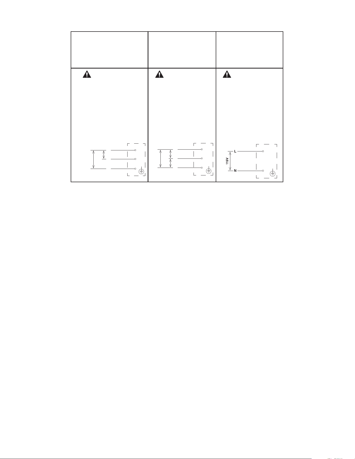
21
Fig. 3
F-1530MAK2(-C)(-SC)
F-1530MWK2(-C)(-SC)
F-1530MRKZ2(-C)(-SC)
F-2030MWK2(-C)
F-2030MRKZ2(-C)(-SC)
F-2030MRKZ3 F-2030MLKZ
WARNING
ELECTRICAL CONNECTION
THIS UNIT MUST BE GROUNDED
Failure to properly ground or wire this unit
could result in death,
serious injury, or severe damage to the
icemaker. The white lead must be connected
to the neutral
conductor of the power source.
See diagram below.
208-230/60/1
(3 wire with neutral for 115V)
JUNCTION BOX
WARNING
ELECTRICAL CONNECTION
THIS UNIT MUST BE GROUNDED
Failure to properly ground or wire
this unit could result in death,
serious injury, or severe damage to the
icemaker.
This unit must be connected to a
three-phase power source.
The transformer’s voltage tap switch
must be positioned to match incoming
voltage at startup.
See diagram below.
208-230/60/3 JUNCTION BOX
WARNING
ELECTRICAL CONNECTION
THIS UNIT MUST BE GROUNDED
Failure to properly ground or wire
this unit could result in death,
serious injury, or severe damage
to the icemaker. The white lead
must be connected to the neutral
conductor of the power source.
See diagram below.
115/60/1
JUNCTION BOX
208-230
V
BLACK
BROWN
L1
L2
WHITE
N
1
15-
120V
BROWN
208-230
V
BLACK
L1
L3
RED
L2
208-
230V
208-
230V
BLACK
WHITE
22
F. Water Supply and Drain Connections
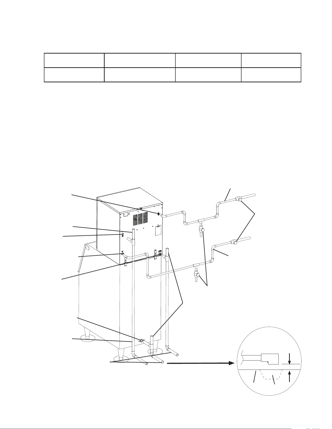
See Fig. 4, 5, and 6
WARNING
• Water supply and drain connections must be installed in accordance with
applicable national, state, and local regulations.
• Connect to potable water supply only. Do not connect to a hot-water supply.
NOTICE
• Water supply line size is critical to the operation of the appliance. Failure to
provide adequate water supply to the appliance may result in damage to the
appliance, damage to property, and may void the warranty.
• Normal operating water temperature must be within 45°F to 90°F (7°C to
32°C). Operation of the appliance, for extended periods, outside of this normal
temperature range may affect appliance performance.
• Water supply pressure must be a minimum of 10 PSIG (69 kPaG) and a maximum
of 113PSIG (779 kPaG). If the pressure exceeds 113 PSIG (779 kPaG), the use
of a pressure reducing valve is required.
• External lters, strainers, or softeners may be required depending on water quality.
Contact your local Hoshizaki Certied Service Representative or local Hoshizaki
distributor for recommendations.
• In areas where water damage is a concern, install in a contained area with a oor
drain.
• Water line installation to the appliance is not warranted by Hoshizaki.
• Be sure there is sufficient extra water supply line and drain line for the appliance
to be pulled out for service.
• Water-hammer issues must be resolved by a qualied plumber before installing
the appliance. Water hammer can cause appliance damage that may lead to
water leakage or ooding.
• A minimum of 3/4" nominal ID hard pipe or equivalent is required for the drain
line. Installing a smaller diameter drain line will reduce water ow and may lead to
water leakage or ooding.
• A plumbing permit and services of a licensed plumber may be required in some areas.
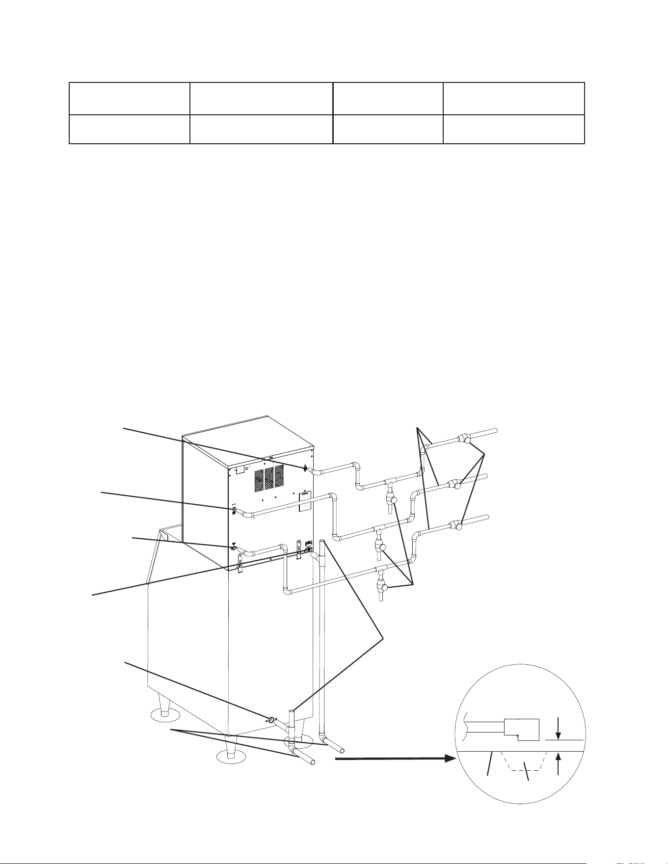
• The icemaker drain line, dispenser unit/ice storage bin drain line, and water-cooled
condenser drain line (if applicable) must be run separately.
• Drain lines must have 1/4" fall per foot (2 cm per 1 m) on horizontal runs to get a good
ow. A vented tee connection is also required for proper ow.
• Drain lines should not be piped directly to the sewer system. An air gap of a minimum of
2 vertical inches (5 cm) must be between the end of the drain pipes from the icemaker,
dispenser unit/ice storage bin, and water-cooled condenser (if applicable) and the oor
drain.
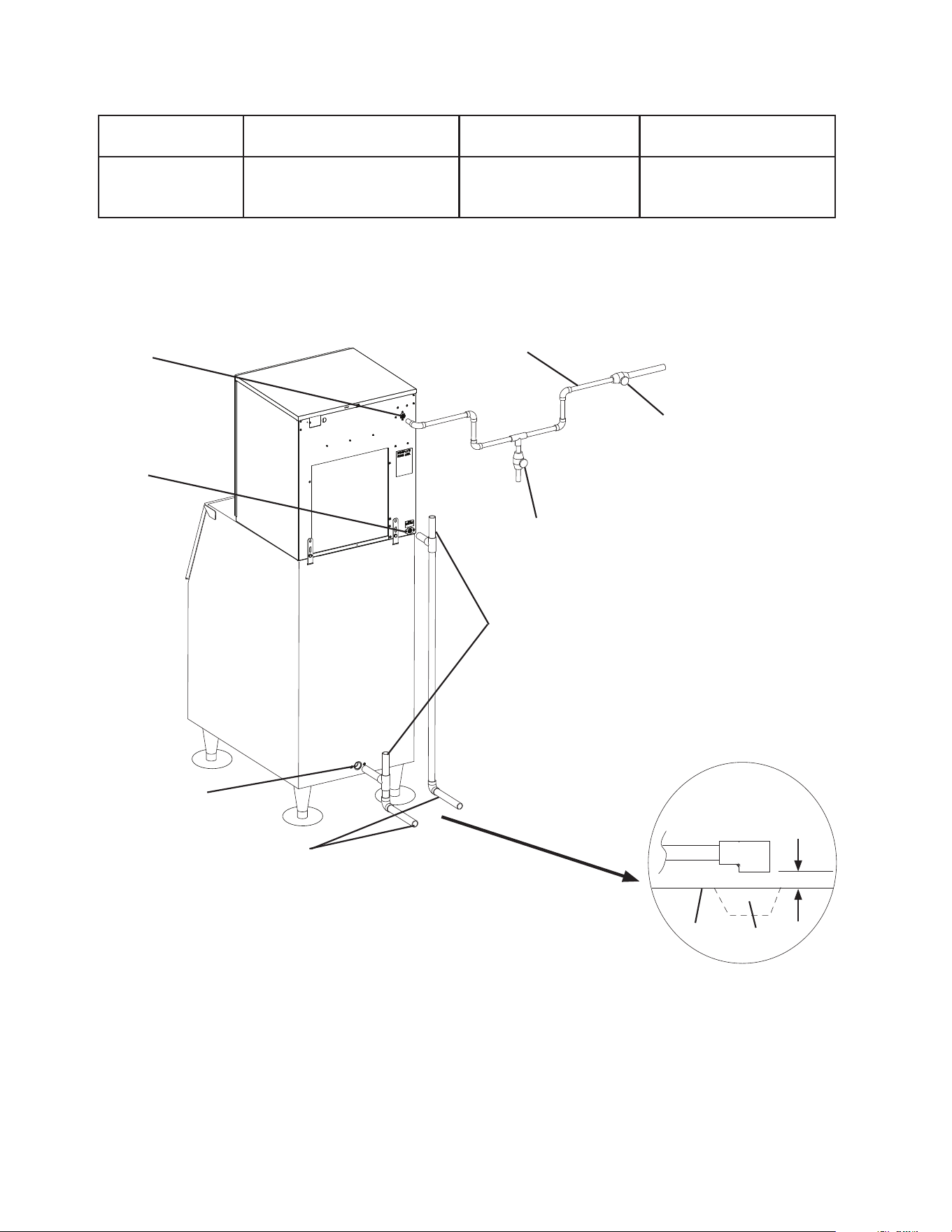
23
Icemaker
Water Supply
Inlet
1/2" FPT
Icemaker
Drain Outlet
3/4" FPT
Bin Drain Outlet
3/4" FPT
Minimum 3/4" Nominal ID
Hard Pipe or Equivalent
Fig. 4
Icemaker
Ice
Storage
Bin
Shut-Off Valve
Drain Valve
Air-Cooled, Remote, and Low-Side Models
2" (5 cm) air gap
Floor
Drain
1. Icemaker
Icemaker Water
Supply Inlet
Minimum Icemaker
Water Supply Line Size
Icemaker Drain
Outlet
Minimum Icemaker Drain
Line Size
1/2" Female Pipe
Thread (FPT)
1/4" Nominal ID
Copper Water Tubing or
Equivalent
3/4" Female Pipe
Thread (FPT)
3/4" Nominal ID Hard Pipe
or Equivalent
• A water supply line shut-off valve and drain valve must be installed.
Minimum 1/4" Nominal ID Copper Water
Tubing or Equivalent
Vent Tube
Be sure there is sufficient
extra water supply line and
drain line for the appliance
to be pulled out for service.
Separate piping to approved
drain. Leave a 2" (5 cm)
vertical air gap between the
end of each pipe and the
drain.
24
Icemaker Water
Supply Inlet 1/2"
FPT
Vent Tube
Condenser
Drain Outlet
3/8" FPT
Condenser Water
Supply Inlet
1/2" FPT
Icemaker
Drain Outlet
3/4" FPT
Bin Drain Outlet
3/4" FPT
Minimum 1/4"
Nominal ID Hard Pipe
or Equivalent
Minimum 3/4" Nominal ID
Hard Pipe or Equivalent
Icemaker
Ice
Storage
Bin
Drain
Valve
Shut-Off Valve
2" (5 cm) air gap
Floor
Drain
2. Water-Cooled Condenser
a) Connection to an Open Drain System
Condenser Water
Supply Inlet
Minimum Condenser
Water Supply Line Size
Condenser Drain
Outlet
Minimum Condenser
Drain Line Size
1/2" Female Pipe
Thread (FPT)
1/4" Nominal ID Copper
Water Tubing or Equivalent
3/8" Female Pipe Thread
(FPT)
1/4" Nominal ID Hard
Pipe or Equivalent
• A condenser water supply line shut-off valve and drain valve must be installed.
• In some areas, a back ow preventer may be required in the cooling water circuit.
• In order to maintain the proper high side pressure, the condenser water supply
inlet temperature should not drop below 45°F (7°C) and the condenser drain outlet
temperature must be in the 104°F to 115°F (40°C to 46°C) range. Once the icemaker
installation is complete, conrm the condenser drain outlet temperature 5 minutes
after a freeze cycle starts. If the condenser drain outlet temperature is not in the
proper range, use a at blade screwdriver to rotate the adjustment screw on the water-
regulating valve until the temperature is in the proper range (rotate counterclockwise to
raise temperature or clockwise to lower temperature).
Minimum 1/4" Nominal ID Copper Water
Tubing or Equivalent
Water-Cooled Models
Connection to an Open Drain System
Fig. 5
Minimum 1/4" Nominal ID Copper
Water Tubing or Equivalent
Be sure there is sufficient
extra water supply line and
drain line for the appliance
to be pulled out for service.
Separate piping to approved
drain. Leave a 2" (5 cm)
vertical air gap between the
end of each pipe and the
drain.
Vent Tube
25
Icemaker Water
Supply Inlet 1/2"
FPT
Condenser
Return Outlet
3/8" FPT
Condenser Water
Supply Inlet
1/2" FPT
Icemaker
Drain Outlet
3/4" FPT
Bin Drain Outlet
3/4" FPT
Minimum 3/4" Nominal ID
Hard Pipe or Equivalent
Fig. 6
Icemaker
Ice
Storage
Bin
Minimum 1/4" Nominal ID Copper Water
Tubing or Equivalent
Drain
Valve
Water-Cooled Models
Connection to a Closed Loop System
Shut-Off Valve
2" (5 cm) air gap
Floor
Drain
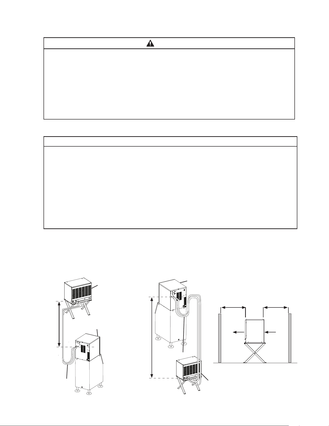
b) Connection to a Closed Loop System
Condenser Water
Supply Inlet
Minimum Condenser
Water Supply Line Size
Condenser Return
Outlet
Minimum Condenser
Return Line Size
1/2" Female Pipe
Thread (FPT)
1/4" Nominal ID Copper
Water Tubing or Equivalent
3/8" Female Pipe
Thread (FPT)
1/4" Nominal ID Copper
Water Tubing or Equivalent
• Shut-off valves and drain valves must be installed at both the condenser water supply
inlet and condenser return outlet.
• Minimum water ow to the condenser is 4 GPM (15 LPM).
• The pressure differential between the condenser water supply inlet and condenser
return outlet must be no less than 10 PSIG (69 kPaG).
• When using a glycol blend, the solution mixture must be less than 30% glycol.
• In order to maintain the proper high side pressure, the condenser water supply inlet
temperature should not drop below 45°F (7°C) and the condenser return outlet
temperature must be in the 104°F to 115°F (40°C to 46°C) range. Once the icemaker
installation is complete, conrm the condenser return outlet temperature 5 minutes
after a freeze cycle starts. If the condenser return outlet temperature is not in the
proper range, use a at blade screwdriver to rotate the adjustment screw on the water-
regulating valve until the temperature is in the proper range (rotate counterclockwise to
raise temperature or clockwise to lower temperature).
Be sure there is sufficient
extra water supply line and
drain line for the appliance
to be pulled out for service.
Separate piping to approved
drain. Leave a 2" (5 cm)
vertical air gap between the
end of each pipe and the
drain.
Vent Tube
26
Service Loop
Remote
Condenser
Unit
Icemaker
Fig. 7
Max.
10'
(3 m)
Service Loop
Remote
Condenser
Unit
Air
G. Remote Condenser Unit Installation
WARNING
• Installation of remote condenser unit must be performed by properly trained and
EPA-certied service personnel.
• The remote condenser unit must be installed in accordance with applicable national,
state, and local codes and regulations.
• Failure to install the remote condenser unit within these guidelines may adversely
affect safety, performance, component life, and warranty coverage.
• Power supply and ground wire to the remote condenser unit are supplied from the
icemaker. For details, see section "II.G.6. Electrical Connection."
1. Location
NOTICE
• The remote condenser unit is intended for outdoor use. Normal operating ambient
temperature must be within -20°F to +122°F (-29°C to +50°C). Operation of the
remote condenser unit, for extended periods, outside of this normal temperature
range may affect appliance performance.
• The maximum line length for the standard line sizes and refrigerant charge is 66'
(20 m). With larger line sizes and/or additional refrigerant, the maximum line length is
100' (30.5 m). For details, see "II.G.4 Line Set Size and Refrigerant Charge."
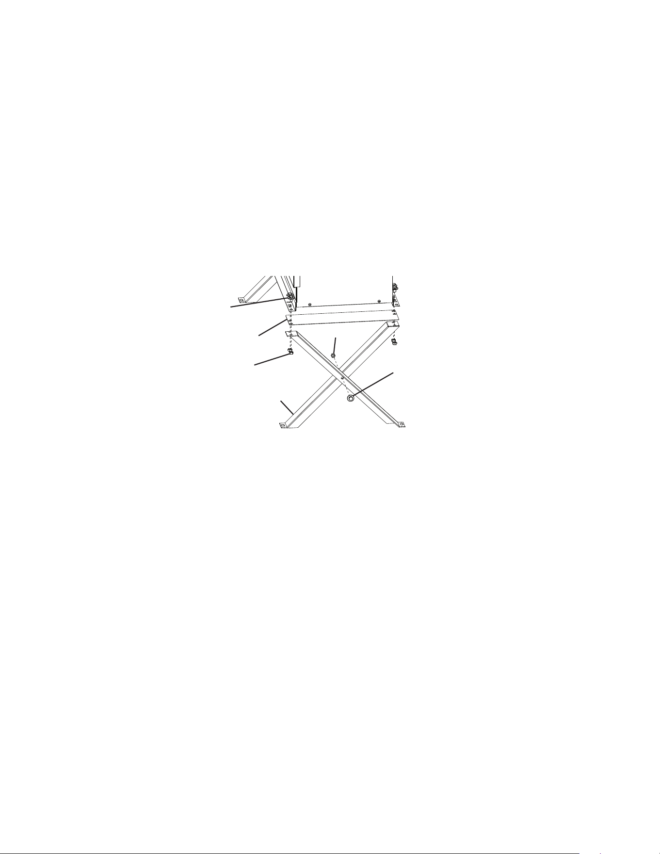
• The maximum vertical distance between the remote condenser unit and the icemaker
is 33' (10 m) above or 10' (3 m) below the icemaker. These distances are measured
tting to tting. See Fig. 7.
The remote condenser unit must be positioned in a permanent site under the following
guidelines:
• A rm and at site.
• A dry and well ventilated area with 24" (61 cm) clearance at front and rear for proper air
circulation and ease of maintenance and/or service should they be required. See Fig. 8.
Max.
33'
(10 m)
Min. 24" (61 cm) Clearance
Fig. 8
Icemaker
Air
27
Bolt with Split Lock
Washer and Flat Washer
Leg
Nut
2. Checks Before Installation
1) Remove the shipping carton, tape, and packing material.
2) Check that the refrigerant lines do not rub or touch lines or other surfaces, and that the
fan blades move freely.
3. Setup
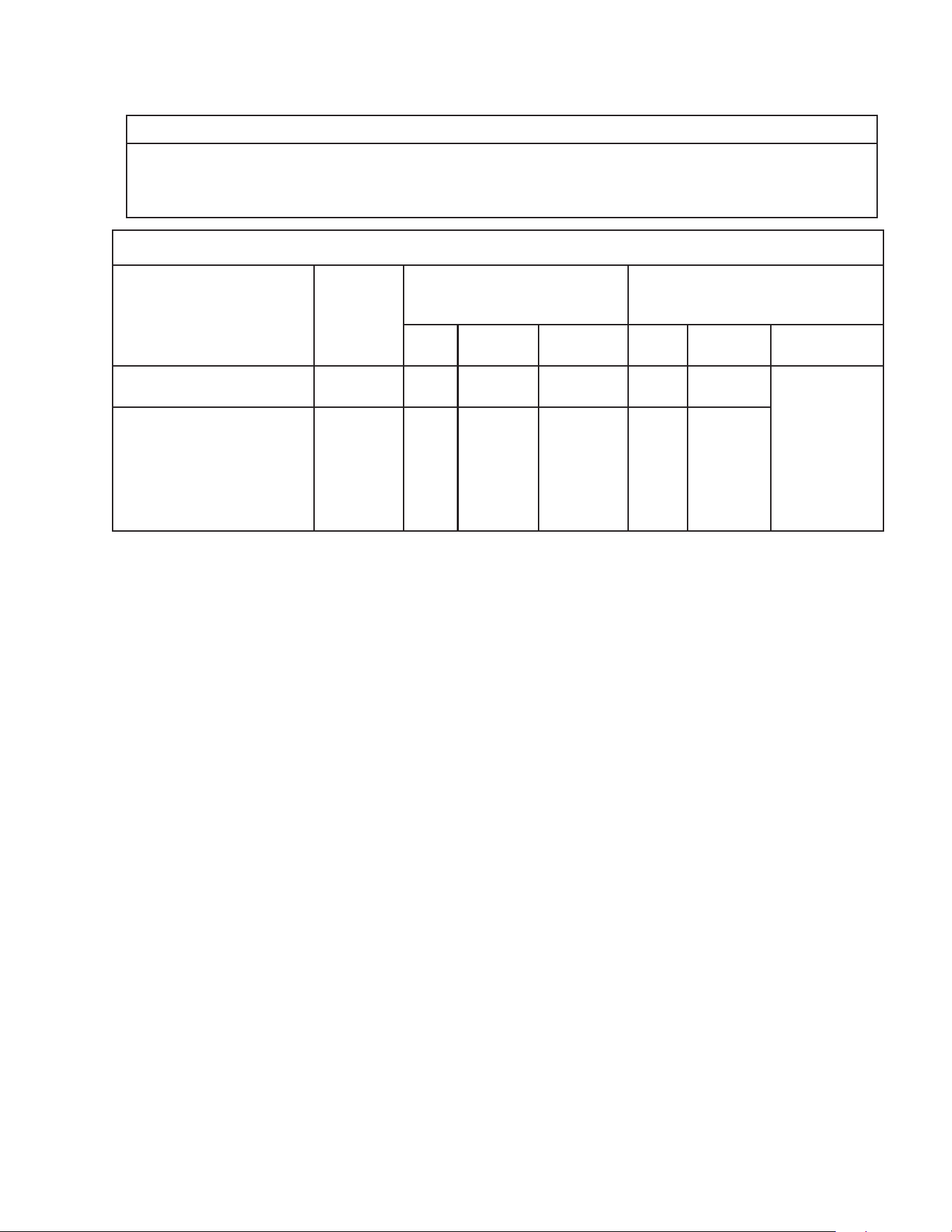
1) Assemble 2 sets of legs using the legs, bolts, and nuts provided. See Fig. 9
2) Position 1 of the plates provided between a set of legs and the remote condenser unit,
then secure the legs to the remote condenser unit with the bolts and nuts provided.
Repeat on the other side with the remaining set of legs.
3) The bottom of each leg has a mounting hole. Secure the legs to the permanent site with
4 bolts (not included).
Fig. 9
Bolt with Split Lock
Washer and Flat Washer
Plate
Nut
28
4. Line Set Size and Refrigerant Charge
NOTICE
The icemaker, line set, and remote condenser unit must contain the same type
of refrigerant. Mixing of refrigerants will result in improper operation and possible
damage to the refrigeration system.
Line Set Size and Refrigerant Charge
Hoshizaki
Icemaker
Hoshizaki
Remote
Condenser
Unit
Line Set
Up to 66' (20 m)
Line Set
Greater than 66' (20 m)
Maximum 100' (30.5 m)
Liquid
Line
Discharge
Line
Charge
Adjustment
Liquid
Line
Discharge
Line
Charge Adjust-
ment (R-448A)
F-1530MRKZ2(-C)(-SC) URC-14KZ 3/8"
OD
1/2" OD Not
Applicable
3/8"
OD
1/2" OD Add 0.4 oz.
for each foot
over 66' (40 g
for each meter
over 20 m).
Write new
total charge
on icemaker’s
rating label.
F-2030MRKZ2(3)(-C)(-SC) URC-26KZ 3/8"
OD
5/8" OD Not
Applicable
3/8"
OD
5/8" OD
29
5. Line Set Installation
WARNING
• R-448A itself is not ammable at atmospheric pressure and temperatures up to
212°F (100°C).
• R-448A itself is not explosive or poisonous. However, when exposed to high
temperatures (open ames), R-448A can be decomposed to form hydrouoric acid
and carbonyl uoride both of which are hazardous.
• Do not use silver alloy or copper alloy containing arsenic.
• Use an electronic leak detector or soap bubbles to check for leaks. Add a trace of
refrigerant to the line set tubing through the service valve access ports (if using
an electronic leak detector), and then raise the pressure using nitrogen gas
(140 PSIG (965 kPaG)). Do not use R-448A as a mixture with pressurized air for
leak testing.
NOTICE
• Do not open any service valve until the line set installation is complete and leak
tested.
• Ensure that there are no traps and no kinks in the line set.
• Do not coil extra line set.
1) Route the factory line set or appropriate size copper tubing. When eld fabricating,
insulate the copper tubes separately. Leave a service loop behind the icemaker to allow
the icemaker to be pulled out for service. See Fig. 7.
Note: • The service loop is not considered an oil trap.
• The maximum line length for the standard line sizes and refrigerant charge is 66'
(20 m). With additional refrigerant, the maximum line length is 100' (30.5 m). For
details, see “II.G.4 Line Set Size and Refrigerant Charge.”
2) Remove any extra line set length, then insulate the two copper tubes separately.
3) Remove the Schrader valve cores from the icemaker service valve access ports.
4) Braze the line set copper tubes to the icemaker liquid and discharge line service valves.
NOTICE
• Before brazing, remove the Schrader valve cores from the service valve access
ports.
• When brazing, protect the service valve by using a wet cloth to prevent the service
valve from overheating.
• Braze all ttings while purging with nitrogen gas owing at a pressure of 3 to 4 PSIG
(21 to 28 kPaG).
5) Remove the Schrader valve cores from the condenser unit service valve access ports.
6) Braze the line set copper tubes to the condenser unit liquid and discharge line service
valves.
7) Allow the service valves to cool, then replace the Schrader valve cores. Attach the
gauge manifold hoses.

30
8) Use an electronic leak detector or soap bubbles to check for leaks. Add a trace of
refrigerant to the line set tubing through the service valve access ports (if using an
electronic leak detector), and then raise the pressure using nitrogen gas (140 PSIG
(965 kPaG)). WARNING! Do not use R-448A as a mixture with pressurized air for
leak testing.
9) After checking the line set for leaks, vent the nitrogen charge from the line set.
10) Evacuate the line set. Allow the vacuum pump to pull down to a 29.9" Hg vacuum
Evacuating period depends on pump capacity.
11) After evacuation, charge each line set tube with R-448A vapor to a pressure of 15 to 30
PSIG (103 to 207 kPaG).
12) Close both gauge manifold valves.
13) If the line set exceeds 66' (20 m), see "II.G.4. Line Set Size and Refrigerant Charge" for
proper charging of the appliance. If not, continue to step 14.
14) Open the icemaker service valves rst, then open the remote condenser unit service
valves.
15) Disconnect the gauge manifold hoses.
16) Replace all service valve caps and tighten.
17) Insulate all exposed tubing and ttings.
31
6. Electrical Connection
WARNING
• Electrical connection must meet national, state, and local electrical code
requirements. Failure to meet these code requirements could result in death,
electric shock, serious injury, re, or damage.
• To reduce the risk of electric shock, make all remote condenser unit connections
before connecting the icemaker power supply.
• THE REMOTE CONDENSER UNIT MUST BE GROUNDED. Install a ground wire
from the icemaker fan motor junction box to the remote condenser unit junction box.
Use wire of an appropriate gage and outdoor rating. Failure to properly ground the
remote condenser unit could result in death or serious injury.
• Install line and neutral wires from the fan motor leads in the icemaker fan motor
junction box to the leads in the remote condenser unit junction box. Use wire of an
appropriate gage and outdoor rating.
• Do not connect the fan motor leads in the icemaker to incoming power source. Do not
connect the fan motor leads in the icemaker together. Do not allow the leads
to contact the junction box walls.
• Do not connect the remote condenser unit to an external power source.
NOTICE
On remote models, the appliance must have power for a minimum of 4 hours prior to
startup to prevent compressor damage.
• Usually an electrical permit and services of a licensed electrician are required.
• The opening for the power supply connection is 7/8" DIA to t a 1/2" trade size conduit.
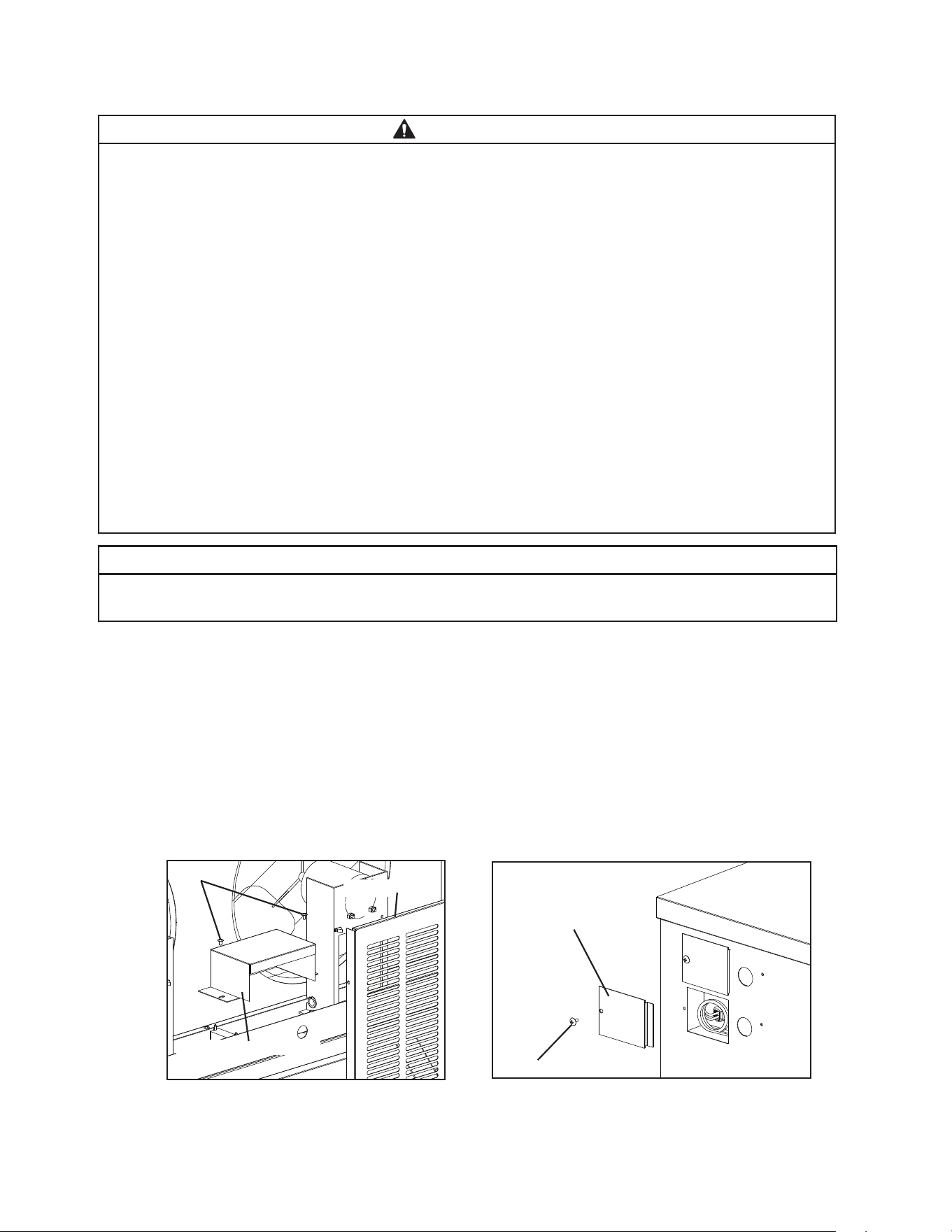
1) Remove the remote condenser unit louver panel. See Fig. 10.
2) Remove the icemaker fan motor junction box cover. Remove the remote condenser unit
junction box cover.
Fig. 10
Remote Condenser Unit
Screws
Louver Panel
Junction Box Cover
Icemaker
Fan Motor Junction
Box Cover
Screw
32
Upper Remote
Condenser Unit
Screws
Lower Remote
Condenser Unit
Screws
Fig. 11
3) Install a ground wire from the icemaker fan motor junction box to the remote condenser
unit junction box. Use wire of an appropriate gage and outdoor rating.
4) Install line and neutral wires from the fan motor leads in the icemaker fan motor junction
box to the leads in the remote condenser unit junction box. Use wire of an appropriate
gage and outdoor rating.
5) Replace the junction box covers and the louver panel in their correct positions.
7. Stacking Remote Condenser Unit
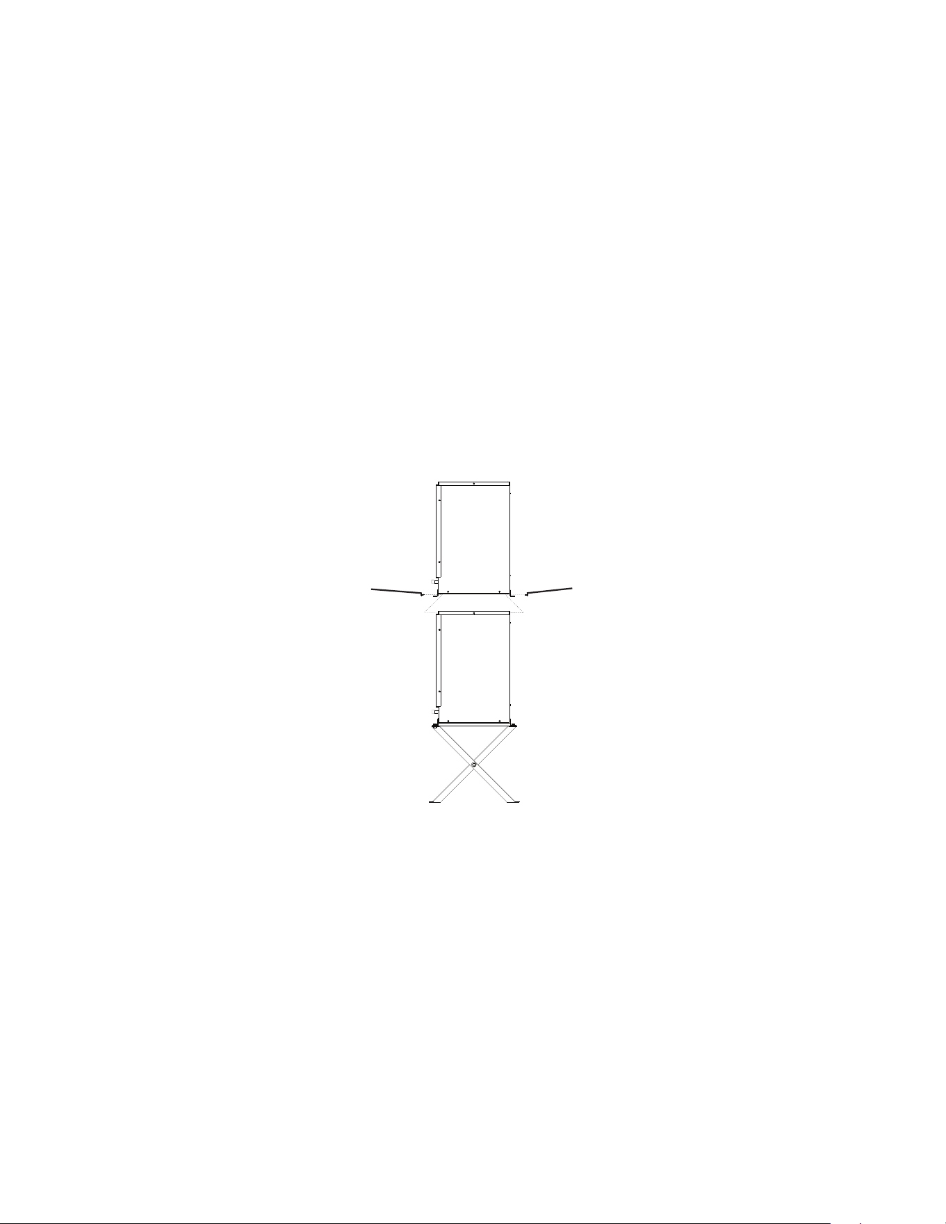
1) Install the lower remote condenser unit as described earlier in this section.
2) Place the upper remote condenser unit on top of the lower remote condenser unit.
See Fig. 11.
3) Secure the upper remote condenser unit to the lower remote condenser unit with the
4 screws provided.
4) Install refrigerant lines and make electrical connection as described earlier in this
section.
33
H. Parallel Rack System Connection
WARNING
• Installation must be performed by properly trained and EPA-certied service
personnel.
• Failure to install the appliance within these guidelines may adversely affect safety,
performance, component life, and warranty coverage.
• Connect the line set to the rack system per the rack system manufacturer’s
instructions.
NOTICE
• The icemaker is shipped with a nitrogen holding charge. Nitrogen must be vented
from multiple points prior to evacuating the refrigeration circuit.
• The icemaker, line set, and rack system must contain the same type of refrigerant.
Mixing of refrigerants will result in improper operation and possible damage to the
refrigeration system.
• Ensure that there are no traps and no kinks in the line set. The service loop is not
considered an oil trap.
• Icemaker may be used with refrigerant R-448A. See table below for EPR valve
settings.
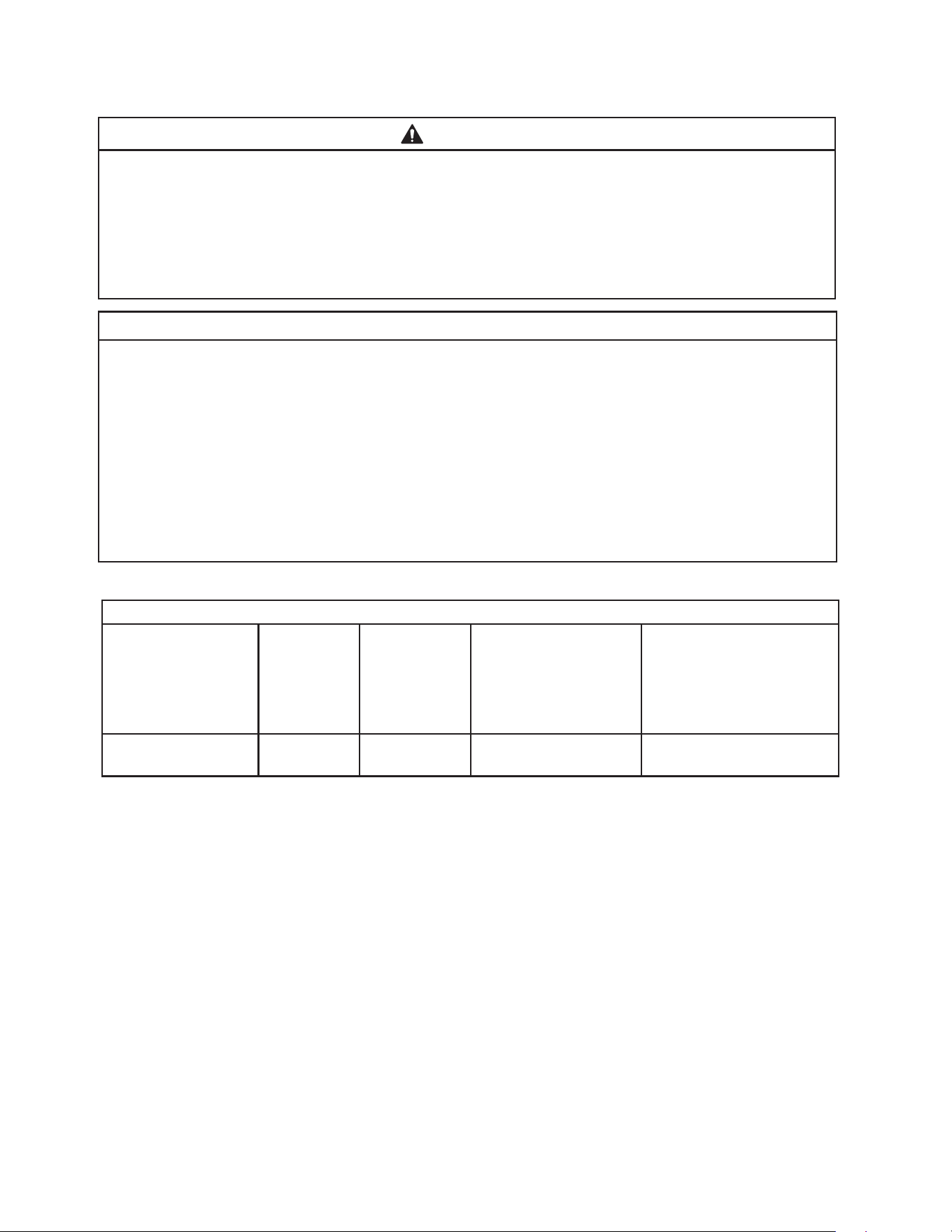
1. Line Set Size and Rack System Requirements
Line Set Size and Rack System Requirements
Hoshizaki Icemaker Liquid Line Suction Line
Maximum Load at
90°F (32°C) Ambient
70°F (21°C) Water
Suction Pressure
(Evaporator Pressure
Regulator (EPR) Valve
is factory adjusted for
R-448A. Adjust only
if necessary.)
F-2030MLKZ 3/8" OD 5/8" OD 15,000 BTU/hr R-448A -
24 PSIG (165 kPaG)
• Install a p-trap in the suction line if required by the rack system manufacturer's
instructions.
34
2. Line Set Installation
WARNING
• Do not use silver alloy or copper alloy containing arsenic.
• Use an electronic leak detector or soap bubbles to check for leaks. Add a trace
of refrigerant to the line set tubing through the service valve access ports
(if using an electronic leak detector), and then raise the pressure using nitrogen gas
(140 PSIG (965 kPaG)). Do not use refrigerant as a mixture with pressurized air for
leak testing.
NOTICE
• Do not open any service valve until the line set installation is complete and leak
tested.
• Ensure that there are no traps and no kinks in the line set.
• Do not coil extra line set.
1) Route the proper size copper tube liquid line and copper tube suction line (see
"II.H.1 Line Set Size and Rack System Requirements" for details) from the rack
system to the icemaker. Leave a service loop behind the icemaker to allow the
icemaker to be pulled out for service. See Fig. 12. Note: The service loop is not
considered an oil trap.
2) Remove any extra line set length, then insulate the two copper tubes separately.
3) Remove the Schrader valve cores from the icemaker service valve access ports.
4) Braze the line set copper tubes to the icemaker liquid and suction line service valves.
NOTICE
• Before brazing, remove the Schrader valve cores from the service valve access
ports.
• When brazing, protect the service valve by using a wet cloth to prevent the service
valve from overheating.
• Braze all ttings while purging with nitrogen gas owing at a pressure of 3 to 4 PSIG
(21 to 28 kPaG).
5) If applicable, remove the rack system service valve Schrader valve core. Connect the
rack system end of the line set per the rack system instructions. NOTICE! Do not open
the rack system service valves at this time.
6) Allow the service valves to cool, then replace the Schrader valve cores in the icemaker
service valves and rack system service valves (if applicable). Attach the gauge manifold
hoses.
7) Use an electronic leak detector or soap bubbles to check for leaks. Add a trace of
refrigerant to the line set tubing through the service valve access ports (if using an
electronic leak detector), and then raise the pressure using nitrogen gas (140 PSIG
(965 kPaG)). WARNING! Do not use refrigerant as a mixture with pressurized air
for leak testing.
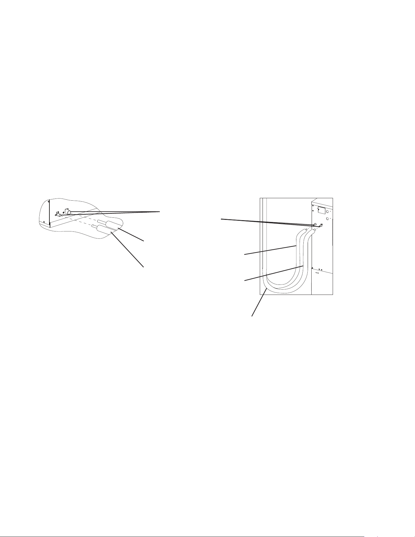
35
Suction Line (Insulated)
See “II.H.1 Line Set Size and Rack
System Requirements” for details.
Liquid Line (Insulated)
See “II.H.1 Line Set Size and Rack
System Requirements” for details.
Model: F-2030MLJ
Service Loop
Icemaker-Braze Connection
8) After checking the line set for leaks, vent the line set nitrogen charge. Next, open both
icemaker service valves and vent the icemaker nitrogen holding charge.
9) After venting the icemaker nitrogen holding charge, evacuate the icemaker and line set.
Allow the vacuum pump to pull down to a 29.9" Hg vacuum. Evacuating period depends
on pump capacity.
10) After evacuation, charge the icemaker and line set with refrigerant vapor (R-448A) to a
pressure of 15 to 30 PSIG (103 to 207 kPaG).
11) Close both gauge manifold valves.
12) Open the rack system service valves.
13) Disconnect the gauge manifold hoses.
14) Replace all service valve caps and tighten.
15) Insulate all exposed tubing and ttings.
Fig. 12
Rack System-Braze Connection
Service Valves
Brazed Connections

36
I. Final Checklist
1. Pre-Startup
1) Is the icemaker level?
2) Is the icemaker in a site where the ambient temperature is within 45°F to 100°F (7°C to
38°C) and the water temperature within 45°F to 90°F (7°C to 32°C) all year around?
3) Is there at least 6" (15 cm) clearance at rear and sides and 24" (61 cm) at the top of the
icemaker?
4) Have the shipping carton, tape, and packing material been removed from the
appliance?
5) Have all electrical and water connections been made? Do electrical and water
connections meet applicable national, state, and local code and regulation
requirements?
6) Has the power supply voltage been checked or tested against the nameplate rating?
Has a proper ground been installed to the icemaker? On remote models, has a proper
ground also been installed to the remote condenser unit?
7) Are the water supply and drain lines sized as specied? Are the water supply line
shut-off valve(s) and drain valve(s) installed? Has the water supply pressure been
checked to ensure a minimum of 10 PSIG (69 kPaG) and a maximum of 113 PSIG
(779 kPaG)?
8) Is the compressor snug on all mounting pads? Have the refrigerant lines been checked
to make sure they do not rub or touch other lines or surfaces? Has the fan blade
(if applicable) been checked to make sure it turns freely?
9) On remote and low side, parallel rack system models, is the line set sized as specied,
insulated, tightened, and free of leaks and kinks?
10) On remote models:
• If the line set exceeds 66' (20 m), has the charge been adjusted as specied?
• Has the appliance power supply been on for a minimum of 4 hours?
• Is the remote condenser unit in a site where the ambient temperature is within -20°F to
+122°F (-29°C to +50°C) all year around?
• Is there at least 24" (61 cm) clearance around the remote condenser unit?
11) On low-side rack systems, has the rack system’s service valves been opened.
12) Continue to "III.B. Startup".

37
2. Post-Startup
1) Has bin control 1 (Ultrasonic) been set to the proper setting for the application?
2) Has bin control 1 (Ultrasonic) operation been conrmed?
3) Has bin control 2 (Mechanical Backup) operation been conrmed?
4) Are all components, fasteners, and thumbscrews securely in place?
5) Has the end user been given the instruction manual, and instructed on how to operate
the appliance and the importance of the recommended periodic maintenance?
6) Has the end user been given the contact information of an authorized service agent?
7) Has the warranty registration been completed and submitted to the factory?
38
III. Operating Instructions
WARNING
• Be sure to follow all Important Safety Information located at the beginning of this
manual.
• Failure to install, operate, and maintain the appliance in accordance with this manual
will adversely affect safety, performance, component life, and warranty coverage and
may result is costly water damage.
A. Important Notes About Usage
NOTICE
• Protect the oor when moving the appliance to prevent damage to the oor.
• Do not leave the appliance on during extended periods of non-use, extended
absences, or in sub-freezing temperatures. To properly prepare the appliance for
these occasions, follow the instructions in "V. Preparing the Appliance for Periods of
Non-Use."
• Do not place objects on top of the appliance.
• The dispenser unit/ice storage bin is for ice use only. Do not store anything else in the
dispenser unit/ice storage bin.
39
B. Startup
1. Bin Control Setting
An ultrasonic sensor is used as the bin control to control the level of ice in the dispenser
unit/ice storage bin. The bin control setting must be set to match the application to avoid
possible icemaker movement, water leakage, or ice overow.
Cubelet ice (-C models) is compatible with cubelet-capable ice dispensers only.
The bin control ice level setting must be changed from the factory default in dispenser
applications; see the setting information below. Note: Hoshizaki DB and DM series ice
dispensers are not cubelet capable. Flaked ice or soft cubelet ice (-SC models) cannot
be dispensed.
WARNING
• Improper adjustment may adversely affect safety, performance, component life, and
warranty coverage.
• On dispenser unit applications, do not increase ice level above the recommended
setting listed below. Higher ice levels could result in icemaker movement, water
leakage, or ice overow.
NOTICE
Do not allow top kits or top kit risers (if applicable) to interfere with the bin control
lens sensing area or the icemaker will not operate properly.
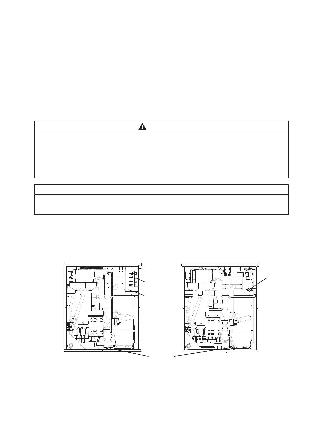
1) Move the power switch to the "OFF" position. Make sure the power supply is off to the
icemaker. Remove the front panel to access the control box assembly. See Fig. 13.
Remove the control box cover to access the control board.
See Fig. 14.
Power
Switch
Control
Box Cover
Fig. 13 Fig. 14
Control Box
Assembly
Control
Board
Ultrasonic
Bin Control
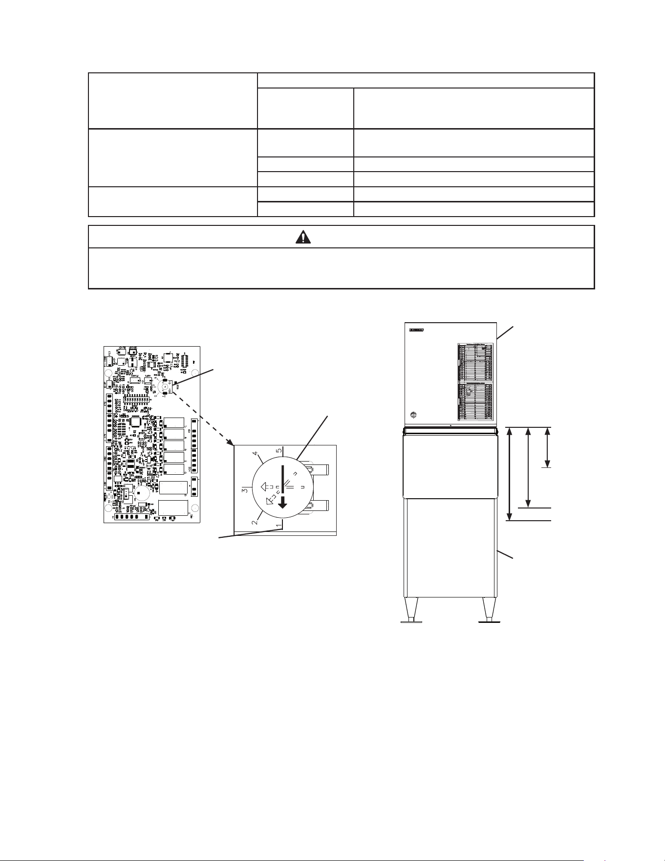
2) Conrm the correct control board bin control setting required for your application and
adjust according to the following tables. See Fig. 15 and Fig. 16.
40
For Standard Ice Storage Bins
Application - All Models Bin Control Ice Level Settings
Bin Control Setting
Shutdown Distance From Bin Control Lens
(Restart is 4" (102 mm) below shutdown
distance)
Standard Ice Storage Bins 1
(Factory Default)
5" ( 127 mm )
Do not adjust ice storage bins to this setting.
2 Do not adjust ice storage bins to this setting.
3 Do not adjust ice storage bins to this setting.
Optional Setting 4 14" (356 mm)
5 18" (457 mm)
WARNING
Conrm that the nal ice level location does not allow for icemaker movement,
water leakage, or ice overow.
Fig. 15
Control Board
Model Shown:
F-1530MAK-C with B-500SF
Icemaker
Standard Ice
Storage Bin
Turn dial to adjust
to proper setting
Factory Default for Standard
Ice Storage Bins
WARNING! Do not use this
setting with dispensers.
Ultrasonic
Bin Control
Lens
Setting #1
Setting #4
Setting #5
Ultrasonic Bin Control
Setting - Ice Level Dial
41
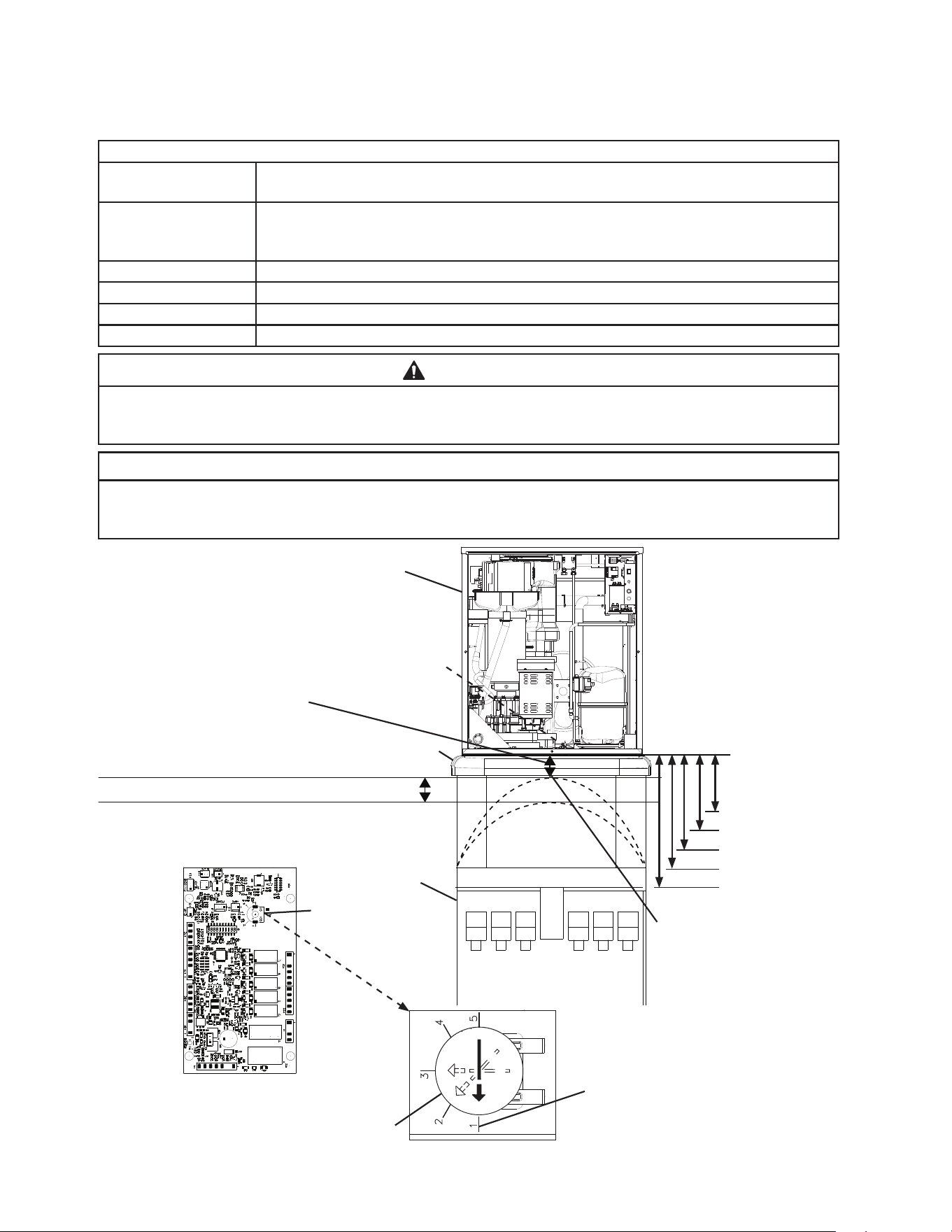
For Non-Hoshizaki Dispenser Units
For cubelet models (-C) only, the bin control ice level setting must be changed from the
factory default setting when used on non-Hoshizaki Dispenser units; see the setting
information below.
Bin Control Ice Level Settings
Bin Control Setting
Shutdown Distance From Bin Control Lens
(Restart is 4 in. (102 mm) below shutdown distance)
1
(Factory Default)
127 mm ( 5" )
Do not use this setting with dispensers;
This setting must be changed for dispenser applications.
2 7" ( 178 mm )
3 10" (254 mm)
4 14" (356 mm)
5 18" (457 mm)
WARNING
Conrm that the nal ice level location does not allow for icemaker movement, water
leakage, or ice overow.
NOTICE
The ice level must be lower than the top of the dispenser unit. Also, be sure the top
kit or top kit riser (if applicable) are clear from the bin control lens sensing area.
Fig. 16
Full Bin Measured Distance
(Shutdown Distance)
Measure from the bottom of
the compressor base (bin
control lens) to the preferred
full bin level of ice; refer to the
dispenser instruction manual.
Icemaker Restart Level
(4" (102 mm) below preferred
full bin level of ice)
Set Bin Control Setting at or Below
Maximum Full Bin Level of Ice
(Shutdown Position) Shown Here
Top Kit
Icemaker
Non-Hoshizaki
Dispenser Unit
Ultrasonic
Bin Control
Control Board
Factory Default for Standard
Ice Storage Bins
WARNING! Do not use this
setting with dispensers.
Turn dial to adjust to setting
that matches Full Bin Measured
Distance (Shutdown Distance)
Ultrasonic
Bin Control
Lens
Setting #1
Setting #3
Setting #4
Setting #5
Setting #2
Maximum Full Bin Level of
Ice (Shutdown Position).
WARNING! Do not adjust
bin control setting above
this level.
Ultrasonic Bin
Control Setting -
Ice Level Dial
42
2. Appliance Startup and Bin Control Check
WARNING
• All parts are factory-adjusted. Improper adjustments may adversely affect safety,
performance, component life, and warranty coverage.
• Make sure the icemaker has been installed as outlined in this manual and that
the water supply is on.
• Improper adjustment may adversely affect safety, performance, component life,
and warranty coverage.
NOTICE
• If the appliance is turned off, wait for at least 3 minutes before restarting the
icemaker to prevent damage to the compressor.
• At startup, conrm that all internal and external connections are free of leaks.
• Do not allow top kits or top kit risers (if applicable) to interfere with the bin control
lens sensing area or the icemaker will not operate properly.
Additional Notice for Remote Models
• The appliance must have power for a minimum of 4 hours prior to startup to
prevent compressor damage.
1) If not already removed, remove the front panel, left side panel, and control box cover.
2) Make sure the power switch is in the "OFF" position and that the power supply is off.
3) Conrm that control board S2 dip switch 1, 2, and 3 are in their proper position per your
application as shown in "III.B.1. Bin Control Setting" above.
4) Move the control switch to the "ICE" position, then move the power switch to the "ON"
position. Turn on the power supply, and allow the icemaker to operate.
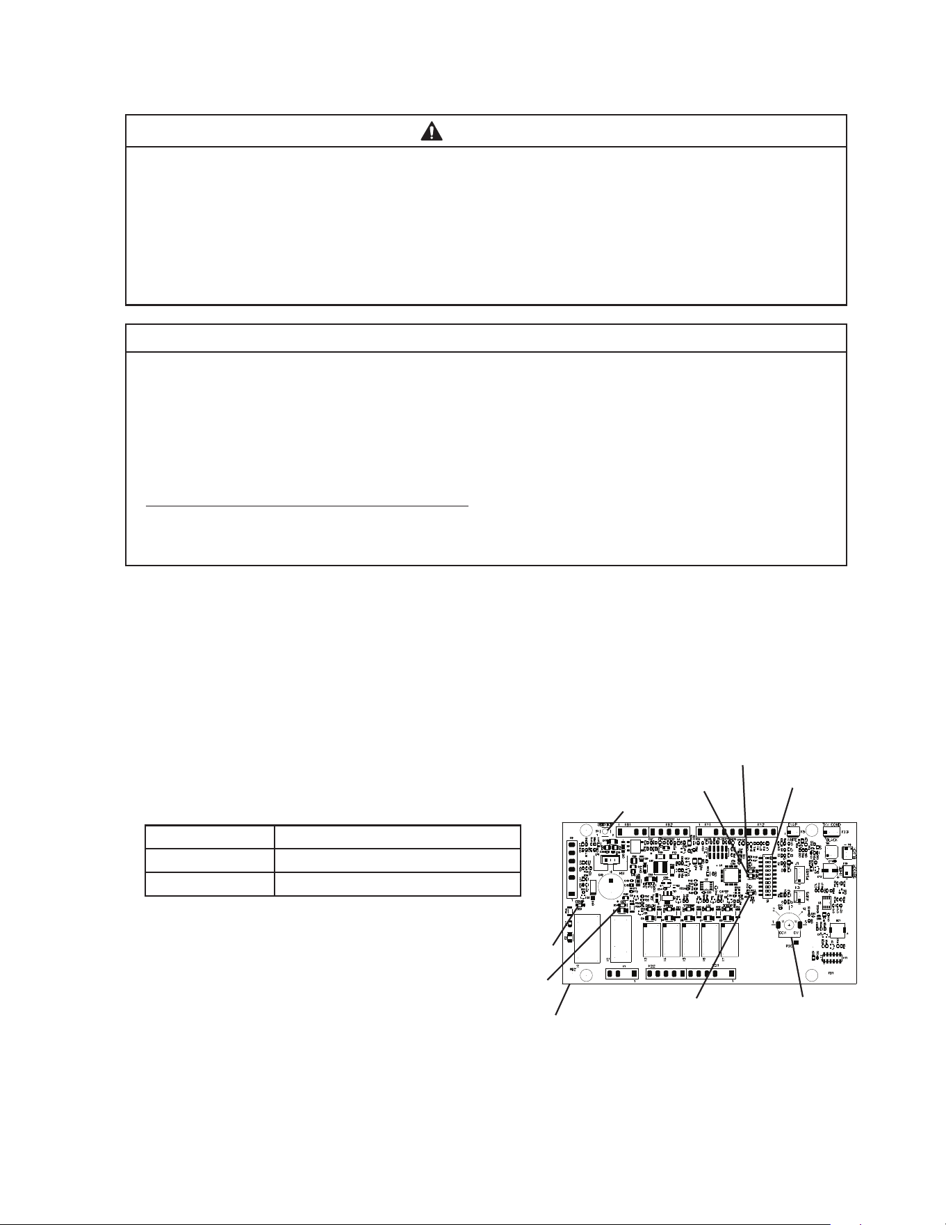
5) Conrm the control board orange "BIN FULL" LED
is off (bin empty). "POWER LED" is on.
See Fig. 17.
Ice Level in Bin Control Board "BIN FULL" LED
Empty OFF
Full ON
6) If the control board "BIN FULL" LED
is on (indicating a full bin), correct
any interference from the top kit or
top kit riser (if applicable).
Control Board
"BIN FULL" LED
Ultrasonic Bin Control
Setting
Fig. 17
"COMP" LED
"GM" LED
"POWER" LED
S2 DIP Switch
"ALARM" LED
"SERVICE" Button
43
7) Make sure the "GM" LED is on. See Fig. 17.
There is a delay of at least 30 sec. before the
"GM" LED turns on after power-up. After "GM"
LED turns on, press the "SERVICE" button on the
control board to bypass the 5-minute compressor
delay. WARNING! Risk of electric shock. Care
should be taken not to touch live terminals.
Conrm the "COMP" LED turns on.
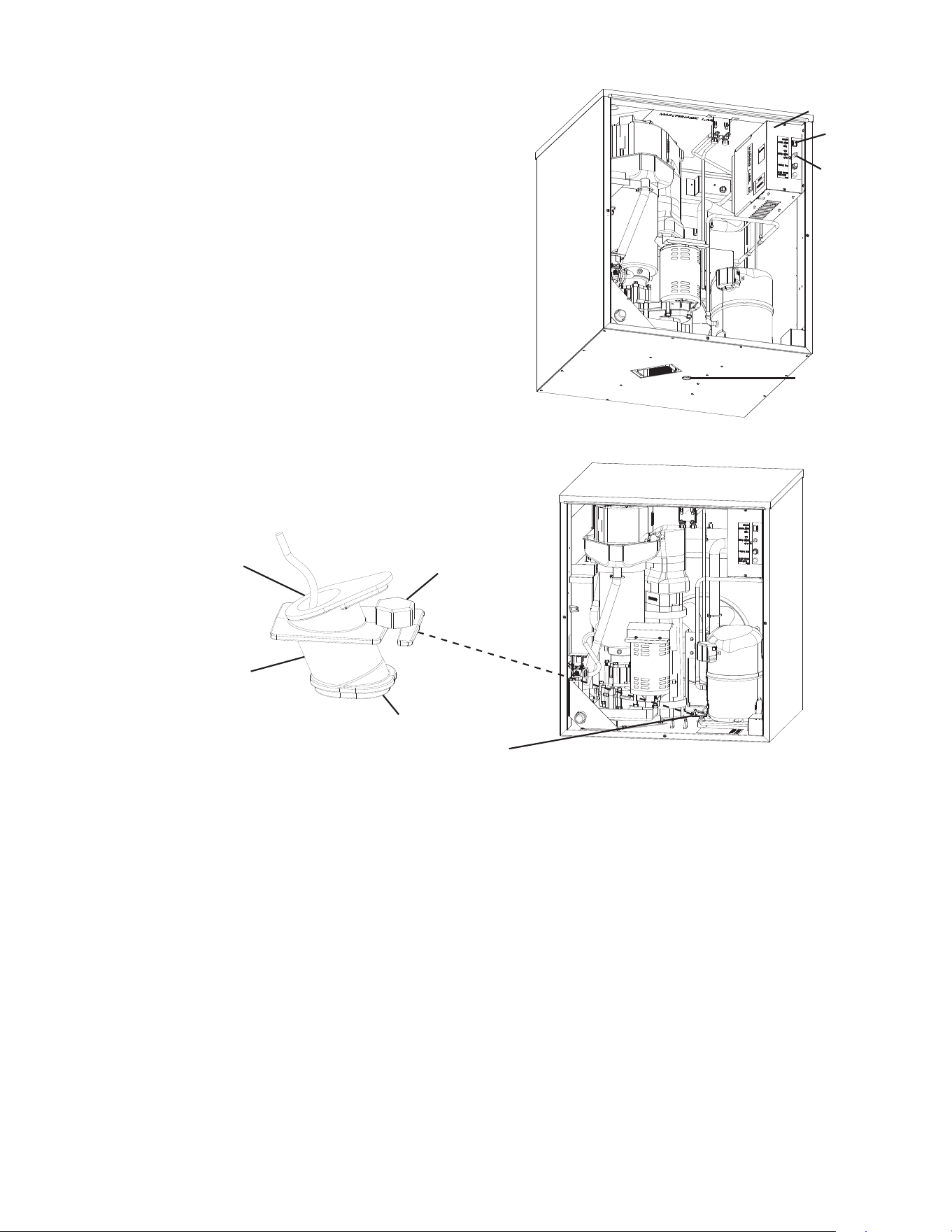
8) "GM" LED and "COMP" LED are on. Place an
object 5" to 7" (127 to 178mm) away from the
bin control lens at the bottom of the icemaker.
See Fig. 18. If the bottom of the icemaker is
not accessible in your application, remove the
thumbscrew securing the bin control sensor
housing to the base, then remove the bin control
housing. See Fig. 19.
9) "BIN FULL" LED turns on. 30 sec. later, the "COMP" LED turns off. Approximately 5 min.
later, "GM" LED turns off. Remove the object from the bin control lens. Approximately
30sec. later, orange "BIN FULL" LED turns off, "GM" LED turns on. Approximately 5
min. later, the "COMP" LED turns on.
10) If you removed the bin control sensor from the base, replace it back in its correct
position and secure with thumbscrew.
11) Replace the left side panel in its correct position.
12) Move the power switch to the "OFF" position, then turn off power supply. Proceed to
"III.B.3. Bin Control 2 (Mechanical Backup)."
Fig. 19
Ultrasonic
Bin Control
Lens
Power
Switch
Control
Switch
Control
Box Cover
Left Side
Panel
Thumbscrew
Ultrasonic
Bin Control
Ultrasonic
Bin Control
Housing
Lens
Ultrasonic
Bin Control
Fig. 18
44
3. Bin Control 2 (Mechanical Backup)
1) Make sure the power switch is in the "OFF" position and that the power supply is off.
2) If not already removed, remove the front panel, top panel, and control box cover.
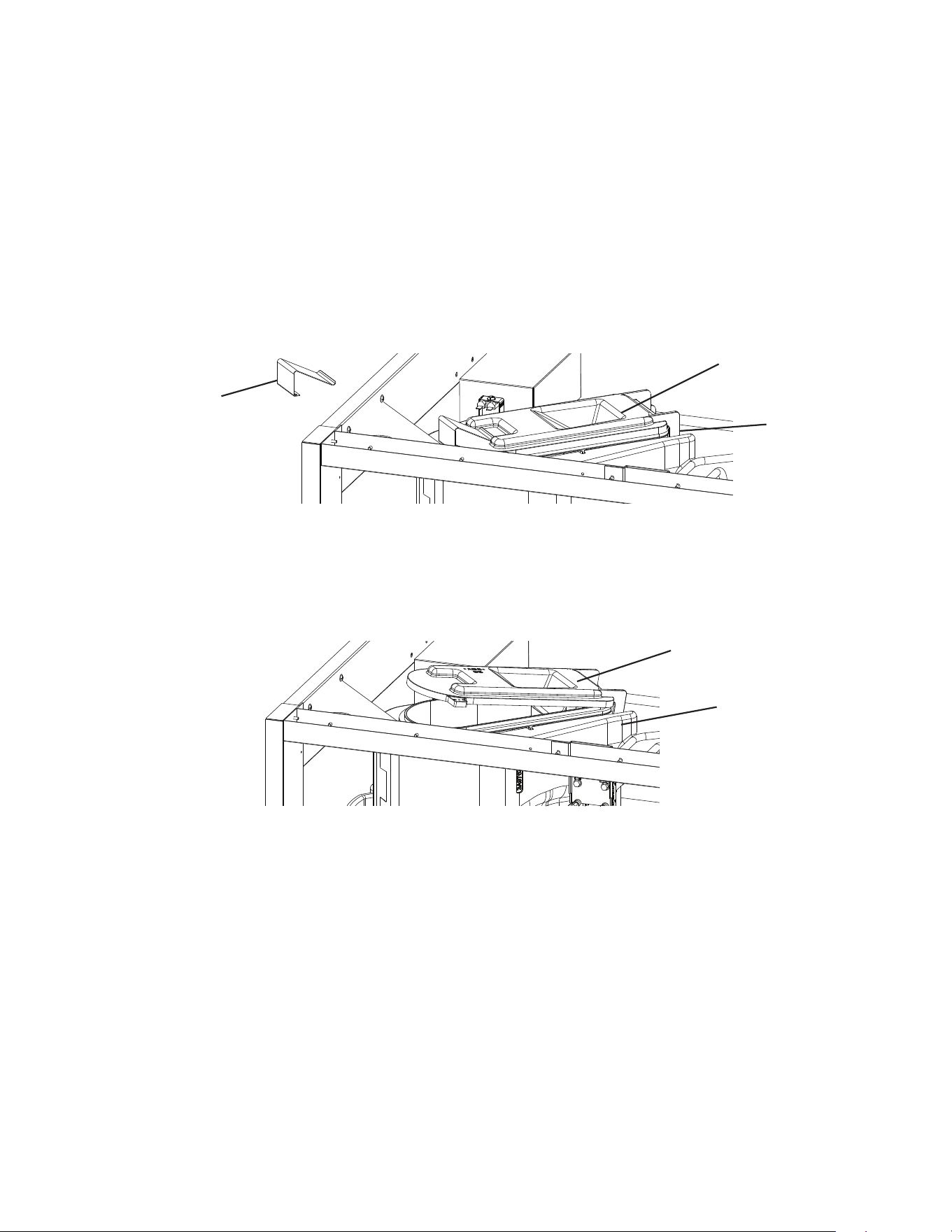
3) Remove the spout insulation and the spout spring from the spout. See Fig. 20.
4) Turn on the power supply. Move the control switch to the "ICE" position, then move the
power switch to the "ON" position.
5) 30 seconds after the upper oat switch closes, the control board "GM" LED turns on.
After "GM" LED turns on, press the "SERVICE" button on the control board to bypass
the 5-minute compressor delay. WARNING! Risk of electric shock. Care should be
taken not to touch live terminals.
6) "GM" LED and "COMP" LED are on. Open the spout cover slightly. See Fig. 21. "GM"
LED and "COMP" LED turn off within 10 seconds and the control board sounds a 9
beep alarm. Close the spout cover.
7) Move the power switch to the "OFF" position, then turn off the power supply.
Note: The control board alarm resets when power is turned off.
8) Replace the spout spring in its correct position.
9) Replace the control box cover and top panel in their correct positions.
10) Turn on the power supply. Make sure the control switch is in the "ICE" position, then
move the power switch to the "ON" position to start the automatic icemaking process.
11) Replace the front panel in its correct position.
12) Return to "II.I.2. Post-Startup" and complete the nal checklist.
Spout
Fig. 20
Spout Cover
Spout
Spout Spring
Spout Cover
Fig. 21
45
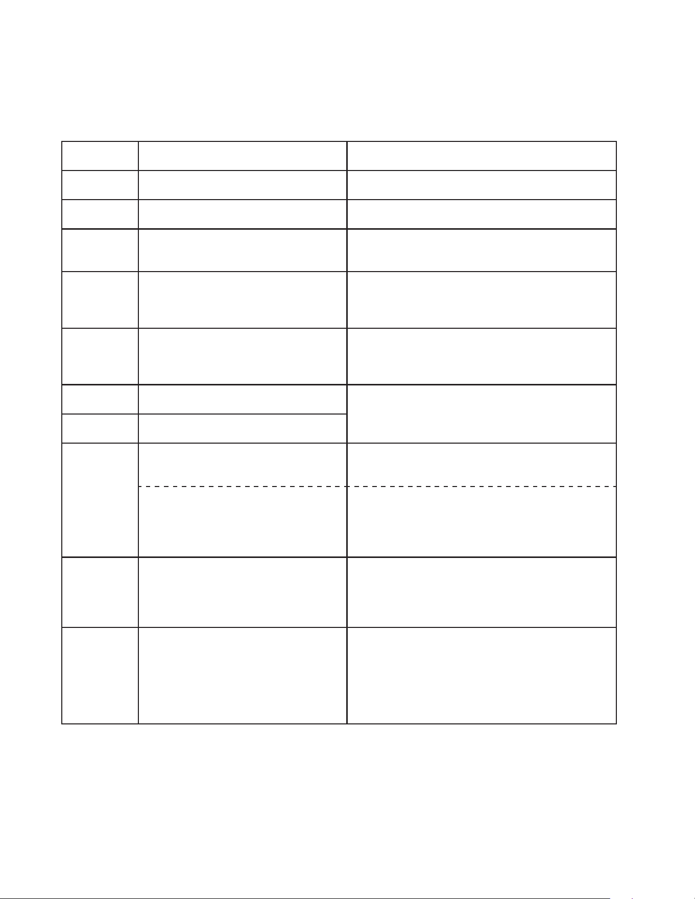
C. Alarm Safeties
Should an alarm occur, follow the instructions in the table below to address the alarm.
If an alarm continues to occur, contact an authorized service agent.
In case of alarm, the built-in safeties shut down the unit, the orange "ALARM" LED turns
on, and audible alarms sound as listed below.
No. of Beeps
(every 5 sec.)
Type of Alarm Notes and Reset Options
1 Low-Water Safety
UFS open
>
90 sec. after WV energized.
Automatic reset once water supply is restored and
UFS closes.
2 Control Switch
In "DRAIN" position longer than 15 min.
Automatic reset once the control switch is moved to
the "ICE" position.
3 High-Pressure Switch
First and second activation in 1 hr.
Automatic reset once pressure drops below the high
pressure threshold and the high-pressure switch
closes.
4 High-Pressure Switch
Third activation in 1 hr.
Turn power off. Call for service.
To avoid possible catastrophic failure, it is
recommended to leave the icemaker off until this
alarm is resolved.
5 Freeze Timer
WV off
>
30 min. since last WV activation.
Call for service. Manual reset. Turn power off and
on again. Check for FS stuck (up), WV leaking by,
TXV defective, LLV not opening, low charge, HM not
bypassing, or inefficient Comp.
6 Low Voltage
92VAC
±
5% or less.
Green "POWER" LED turns off if voltage
protection operates.
Control voltage safeties automatically reset when
voltage is corrected.
7 High Voltage
147VAC
±
5% or more.
8 a) Gear Motor Fuse or Protector Open
CCR contacts fail to close.
Used on all models.
Turn power off. Check for GM fuse or protector open.
Replace fuse or let protector cool and reset.
If persistent trips occur, call for service.
b) Evaporator Thermistor
At GM startup Evaporator
thermistor < -4°F (-20°C).
Used on cubelet (-C), (-SC),
and (-CB) models only.
Turn power off. Call for service.
To avoid possible catastrophic failure, it is
recommended to leave the icemaker off until this
alarm is resolved.
Manual reset. Turn power off and on again.
9 Bin Control 2 (Mechanical)
Open Circuit Control Board K8
(#3 and #4)
Not used on DCM or
self-contained models.
Manual reset. Turn power off and on again.
Modular Flaker and Cubelet (-C)(-SC)(-CB) Models:
Control Board S2 Dip Switch #7 must be ON.
DCM and Self-Contained Models:
Control Board S2 Dip Switch #7 must be OFF.
10 Evaporator Thermistor
Evaporator thermistor reaches -22°F
(-30°C) for 3 consecutive cycles.
Used on cubelet (-C), (-SC),
and (-CB) models only.
Not used on DCM or
self-contained models.
Turn power off. Call for service.
To avoid possible catastrophic failure, it is
recommended to leave the icemaker off until this
alarm is resolved.
Manual reset. Turn power off and on again.
Legend: Comp–compressor; DV–drain valve; EH–evaporator heater; FM–fan motor;
FMR–fan motor-remote; FS–oat switch; GM–gear motor; HM–headmaster
(C.P.R.); L LV -liquid line valve; SLV–suction line valve; TXV–thermostatic
expansion valve; UFS–upper oat switch; WV–inlet water valve
Dip switches are factory set and must be adjusted per the unit’s service manual or
Hoshizaki Technical Support recommendation.
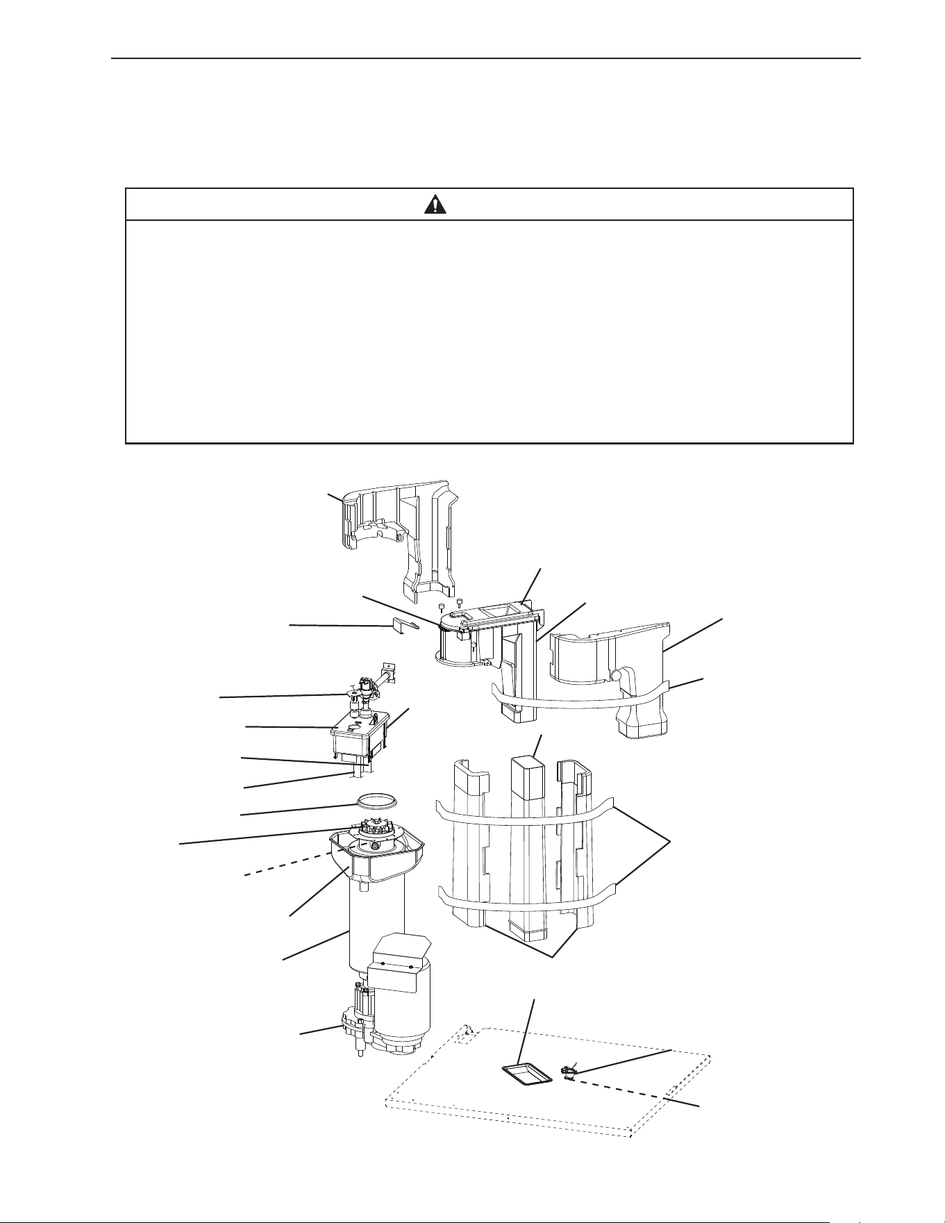
46
IV. Maintenance
The appliance must be maintained in accordance with the instruction manual and labels
provided. Consult with your local Hoshizaki Certied Service Representative about
maintenance service. To obtain the name and phone number of your local Hoshizaki
Certied Service Representative, visit www.hoshizakiamerica.com.
WARNING
• Only qualied service technicians should service the appliance.
• To reduce the risk of electric shock, do not touch the icemaker power switch or
control switch with damp hands.
• Before Servicing: Move the icemaker’s power switch to the "OFF" position. Turn off
the power supply. Place the disconnect (if applicable) in the off position.
Lockout/Tagout to prevent the power supply from being turned back on inadvertently.
• CHOKING HAZARD: Ensure all components, fasteners, and thumbscrews are
securely in place after any maintenance is done to the appliance. Make sure that
none have fallen into the dispenser unit/ice storage bin.
Spout Insulation
Proximity Switch
(mechanical bin control)
Spout Spring
Float Switch
Reservoir Cover
Overow Hose
Reservoir Hose
Spout Packing
Cutter
Extruding Head
Evaporator
Condensate Drain Pan
Evaporator Assembly
Gear Motor
Fig. 22
Reservoir
Spout Cover
Spout
Chute
Chute Insulation
Chute Packing
Insulation Straps
Bin Control Housing
Lens
Spout Insulation
Insulation Strap
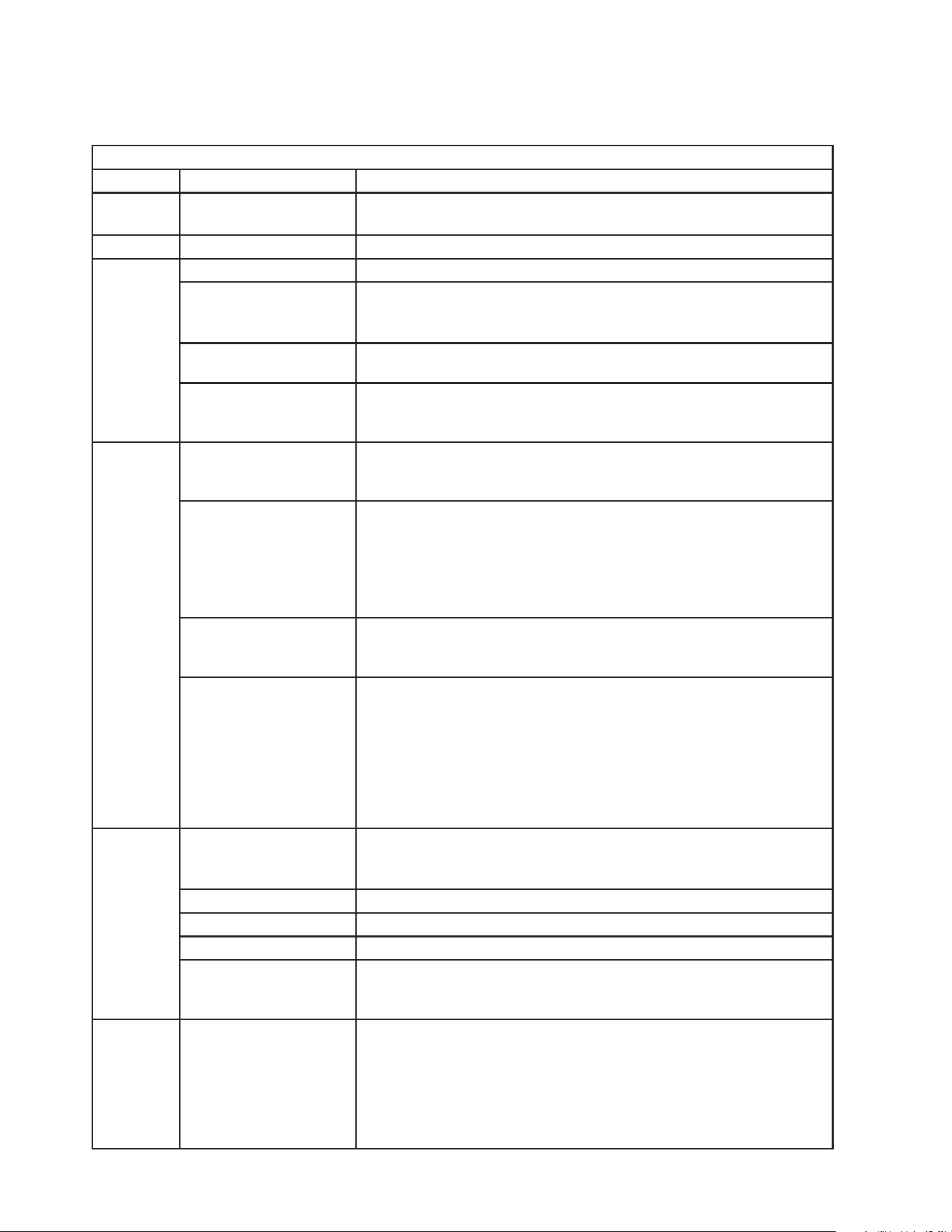
47
A. Maintenance Schedule
The maintenance schedule below is a guideline. More frequent maintenance may be
required depending on water quality, the appliance’s environment, and local sanitation
regulations.
Maintenance Schedule
Frequency Area Task
Daily Scoop Clean the ice scoop using a neutral cleaner. Rinse
thoroughly after cleaning.
Bi-Weekly Air Filters Inspect. Wash with warm water and neutral cleaner if dirty.
Monthly External Water Filters Check for proper pressure and change if necessary.
Icemaker Exterior Wipe down with a clean, soft cloth. Use a damp cloth containing
a neutral cleaner to wipe off oil or dirt build up. Clean any chlorine
staining (rust colored spots) using a non-abrasive cleanser.
Bin Control Lens Wipe down the bin control lens, (located on the bottom of the
icemaker) with a neutral cleaner. Rinse thoroughly after cleaning.
Underside of Icemaker
and Top Kits; Bin Door
and Snout
Wipe down with a clean cloth and warm water.
Every 6
Months
Icemaker and
Dispenser Unit/Ice
Storage Bin
Clean and sanitize per the cleaning and sanitizing instructions
provided in this manual.
Evaporator Condensate
Drain Pan and Gear
Motor Drain Pan
Wipe down with a clean cloth and warm water. Slowly pour one cup
of sanitizing solution (prepare as outlined in the sanitizing
instructions in this manual) into the evaporator condensate drain
pan and then slowly pour one cup into the gear motor drain pan.
Be careful not to overow the pans. Repeat with a cup of clean
water to rinse.
Icemaker and
Dispenser Unit/Ice
Storage Bin Drains
Check to make sure they are clear.
Extruding Head Seal
Bolts
Inspect for leakage around seal bolts. Tighten (see torque values
below) or replace as necessary. Seal bolts must be replaced once
removed because seal material is one-time use only. If new seal
bolts do not have preapplied threadlocker, apply Loctite 243 or
equivalent threadlocker to seal bolt threads.
• Torque for F-1530 and Larger: 25.8 ft-lb/35 N·m
Tighten 2 times. Allow at least 5 sec. in between
each tightening.
Yearly Inlet Water Valve and
Drain Valve
Close the water supply line shut-off valve and drain the water
system. Clean the inlet water valve screen and clean and inspect
the drain valve.
Water Hoses Inspect the water hoses and clean/replace if necessary.
Condenser Inspect. Clean if necessary by using a brush or vacuum cleaner.
Icemaker Inspect for oil spots, loose components, fasteners, and wires
Upper Bearing
(extruding head)
Check for wear using .02" round stock or pin gauge. Replace both
upper bearing and lower bearing if wear exceeds factory
recommendations. See the Service Manual for details.
After 3
Years,
then Yearly
Upper Bearing
(extruding head);
Lower Bearing and
O-Ring (lower housing);
Mechanical
Seal; Evaporator
Cylinder; Auger
Inspect. Replace both upper bearing and lower bearing if wear
exceeds factory recommendations. Replace the mechanical seal
if the seal’s contact surfaces are worn, cracked, or scratched. See
the Service Manual for details.
48
B. Cleaning and Sanitizing Instructions
The appliance must be cleaned and sanitized at least twice a year. More frequent
cleaning and sanitizing may be required in some conditions.
WARNING
• To prevent injury to individuals and damage to the appliance, do not use ammonia
type cleaners.
• Carefully follow any instructions provided with the cleaning and sanitizing solutions.
• Always wear liquid-proof gloves and goggles to prevent the cleaning and sanitizing
solutions from coming into contact with skin or eyes.
• After cleaning and sanitizing, do not use ice made from the cleaning and sanitizing
solutions. Be careful not to leave any solution on the parts or in the dispenser
unit/ice storage bin.
1. Cleaning Solution
Dilute 9.6 . oz. (0.29 l) of Hoshizaki "Scale Away" with 1.6 gal. (6.0 l) of warm water.
This is a minimum amount. Make more solution if necessary. IMPORTANT! For safety
and maximum effectiveness, use the solution immediately after dilution.
2. Cleaning Procedure
1) Close the icemaker water supply line shut-off valve.
2) Turn off the power supply, then remove the front panel. Make sure the power switch is
in the "ON" position, then move the control switch to the "DRAIN" position. Replace the
front panel in its correct position.
3) Turn on the power supply and allow the water system to drain completely.
4) Turn off the power supply, then remove the front and top panels. Move the power switch
to the "OFF" position.
5) Remove all of the ice from the dispenser unit/ice storage bin. WARNING! If on a
dispenser unit, turn off the dispenser unit power supply after dispensing the ice.
6) Remove the spout spring, then open the spout cover. See Fig. 22.
7) Pour the cleaning solution over the extruding head until the evaporator assembly and
the reservoir are full and the solution starts to run through the overow hose on the
reservoir.
Note: If there is excess scale on the extruding head, ll the evaporator assembly and
reservoir as described above, then use a clamp on the reservoir hose between the
reservoir and evaporator assembly to block ow. Pour additional cleaning solution over
the extruding head until the evaporator assembly is completely full.
8) Close the spout cover and replace the spout spring in its correct position.
9) Allow the icemaker to sit for 10 minutes before operation. If you placed a clamp on the
reservoir hose in step 7, remove it before operation.

49
10) In bad or severe water conditions, clean the oat switch as described below. Otherwise,
continue to step 11.
a. Remove the oat switch from the reservoir cover.
b. Wipe down the oat switch with the cleaning solution.
c. Rinse the oat switch thoroughly with clean water.
d. Replace the oat switch in its correct position.
11) Wipe down the bin control lens, (located on the bottom of the icemaker) with the
cleaning solution. Next, rinse the cleaning solution off of the bin control lens with a
clean, damp cloth.
Note: If the bottom of the icemaker is not accessible in your application, remove the
thumbscrew securing the bin control housing, then remove the housing from the
base. After cleaning and rinsing the lens, replace the housing in its correct position and
secure it with the thumbscrew.
12) Move the control switch to the "ICE" position, then move the power switch to the "ON"
position. Replace the panels in their correct positions. Turn on the power supply and
make ice using the solution until the icemaker stops making ice.
13) Turn off the power supply, then remove the front panel. Move the control switch to the
"DRAIN" position, then replace the front panel in its correct position.
14) Turn on the power supply and allow the water system to drain completely.
15) Turn off the power supply, then remove the front panel. Move the control switch to the
"ICE" position, then replace the front panel in its correct position.
16) Open the icemaker water supply line shut-off valve, then turn on the power supply to
supply water to the reservoir.
17) After the gear motor starts, turn off the power supply. Remove the front panel, then
move the control switch to the "DRAIN" position. Replace the front panel in its correct
position.
18) Turn on the power supply and allow the water system to drain completely.
Note: If you do not sanitize the unit, go to step 14 in "III.B.5. Sanitizing
Procedure - Final."
19) Turn off the power supply, then close the icemaker water supply line shut-off valve.

50
3. Sanitizing Solution
Dilute 1.7 . oz. (50 ml or 3.4 tbs) of a 7.5% sodium hypochlorite solution (chlorine bleach)
with 5 gal. (19 l) of warm water. This is a minimum amount. Make more solution
if necessary. IMPORTANT! For safety and maximum effectiveness, use the solution
immediately after dilution.
4. Sanitizing Procedure - Initial
1) Make sure the power supply is off and the icemaker water supply line shut-off valve
is closed. Remove the front and top panels, then move the power switch to the "OFF"
position.
2) Remove the spout spring, then open the spout cover. See Fig. 22. Next, remove the
proximity switch from the spout assembly, then remove the spout and chute assembly,
and spout packing from the icemaker.
3) Pour the sanitizing solution over the extruding head until the evaporator assembly and
the reservoir are full and the solution starts to run through the overow hose on the
reservoir.
4) Remove the spout and chute insulation straps, then remove the spout and chute
insulation and set aside.
5) Soak the spout assembly, chute, and spout packing in the sanitizing solution for 10
minutes then wipe them down. Next, wipe down the chute packing at the base of the
icemaker.
6) Rinse the parts thoroughly with clean water.
7) Replace the spout packing, chute, spout assembly, insulation, and insulation straps in
their correct positions. Next, open the spout cover and replace the proximity switch in its
correct position, then close the spout cover and replace the spout spring in its correct
position. IMPORTANT! Be sure the insulation is placed back in its correct position
and secured with the insulation straps.
8) Move the control switch to the “ICE” position, then move the power switch to the "ON"
position. Replace the panels in their correct positions, then turn on the power supply.
Make ice using the solution until the icemaker stops making ice.
9) Turn off the power supply, then remove the front panel. Move the control switch to the
"DRAIN" position, then replace the front panel in its correct position.
10) Turn on the power supply and allow the water system to drain completely.
11) Turn off the power supply.

51
5. Sanitizing Procedure - Final
1) Dilute 1.7 . oz. (50 ml or 3.4 tbs) of a 7.5% sodium hypochlorite solution (chlorine
bleach) with 5 gal. (19 l) of warm water. This is a minimum amount. Make more solution
if necessary. IMPORTANT! For safety and maximum effectiveness, use the solution
immediately after dilution.
2) Make sure the power supply is off and the icemaker water supply line shut-off valve
is closed. Remove the front and top panels, then move the power switch to the "OFF"
position.
3) Remove the spout spring and open the spout cover.
4) Pour the sanitizing solution over the extruding head until the evaporator assembly and
the reservoir are full and the solution starts to run through the overow hose on the
reservoir.
5) Close the spout cover, then replace the spout spring in its correct position.
6) Allow the icemaker to sit for 10 minutes before operation.
7) Move the control switch to the "ICE" position, then move the power switch to the "ON"
position. Replace the panels in their correct positions, then turn on the power supply.
Make ice using the solution until the icemaker stops making ice.
8) Turn off the power supply, then remove the front panel. Move the control switch to the
"DRAIN" position, then replace the front panel in its correct position.
9) Turn on the power supply and allow the water system to drain completely.
10) Turn off the power supply, then remove the front panel. Move the control switch to the
"ICE" position, then replace the front panel in its correct position.
11) Open the icemaker water supply line shut-off valve, then turn on the power supply to
supply water to the reservoir.
12) After the gear motor starts, turn off the power supply. Remove the front panel, then move
the control switch to the "DRAIN" position. Replace the front panel in its correct
position.
13) Turn on the power supply and allow the water system to drain completely.
14) Turn off the power supply, then remove the front panel. Move the control switch to the
"ICE" position, then replace the front panel in its correct position.
15) Turn on the power supply to start the automatic icemaking process. Allow the icemaker
to run for 30 minutes, then turn off the power supply.
16) Pour warm water into the dispenser unit/ice storage bin and melt any remaining ice.
Clean the dispenser unit/ice storage bin liner using a neutral cleaner. Rinse thoroughly
after cleaning.
17) Turn on the power supply to start the automatic icemaking process.
Note: If on a dispenser unit, turn on the dispenser unit power supply.
52
V. Preparing the Appliance for Periods of Non-Use
WARNING
Only qualied service technicians should service this appliance.
NOTICE
• During extended periods of non-use, extended absences, or in sub-freezing
temperatures, follow the instructions below to reduce the risk of costly water
damage.
• When the appliance is not used for two or three days under normal conditions, it
is sufficient to move the power switch to the "OFF" position.
1. Remove the water from the icemaker water supply line:
1) Turn off the power supply, then remove the front panel.
2) Move the power switch to the "OFF" position.
3) Close the icemaker water supply line shut-off valve, then open the icemaker water
supply line drain valve.
4) Allow the line to drain by gravity.
5) Attach a compressed air or carbon dioxide supply to the icemaker water supply line
drain valve.
6) Move the control switch to the "ICE" position, then move the power switch to the "ON"
position. Replace the front panel in its correct position, then turn on the power supply.
7) Blow the icemaker water line out using the compressed air or carbon dioxide supply.
8) Close the icemaker water supply line drain valve.
2. Drain the evaporator:
1) Turn off the power supply, then remove the front panel.
2) Move the control switch to the "DRAIN" position, then replace the front panel in its
correct position.
3) Turn on the power supply and allow the water system to drain for 5 minutes.
4) Turn off the power supply, then remove the front panel. Move the power switch to the
"OFF" position.
5) Remove the evaporator drain line hose from the evaporator and attach a compressed air
or carbon dioxide supply to the hose.
6) Turn on the power supply, then move the power switch to the "ON" position. Blow out
the evaporator drain line using the compressed air or carbon dioxide supply until water
stops coming out.

53
7) Move the power switch to the "OFF" position, then turn off the power supply.
Reconnect the evaporator drain line hose removed in step 5.
8) Move the control switch to the "ICE" position. Replace the front panel in its correct
position.
9) Remove all ice from the dispenser unit/ice storage bin. Clean the dispenser unit/ice
storage bin liner using a neutral cleaner. Rinse thoroughly after cleaning.
3. On water-cooled models, remove the water from the water-cooled condenser:
1) Make sure the power supply is off, then remove the front panel, top panel, and right side
panel.
2) Close the condenser water supply line shut-off valve. If connected to a closed loop
system, also close the condenser return line shut-off valve.
3) Open the condenser water supply line drain valve. If connected to a closed loop system,
also open the condenser return line drain valve.
4) Attach a compressed air or carbon dioxide supply to the condenser water supply line
drain valve.
5) Open the water regulating valve by using a screwdriver to pry up on the spring retainer
underneath the spring. While holding the valve open, blow out the condenser using the
compressed air or carbon dioxide supply until water stops coming out.
6) Close the drain valve(s).
7) Replace the right side, top, and front panels in their correct positions.
54
VI. Decommissioning and Disposal
WARNING
• Only qualied service technicians should install and service the appliance.
• Follow handling instructions carefully in compliance with national regulations.
• Dispose of properly in accordance with federal or local regulations.
• Be sure to follow the full Decommissioning and Disposal information located in the
Service Manual for this model. The Service Manual is available at
www.hoshizakiamerica.com.
55
618 Hwy. 74 South, Peachtree City, GA 30269 USA (P) 770.487.2331 (F) 770.487.3360 hoshizakiamerica.com 1A8255-011