FOR YOUR SAFETY!
WARNING: If the information in these instructions are not followed exactly, a fire or explosion may result causing
property damage, personal injury or death.
NOTICE: This water heater is designed for use in a commercial application and the installation and maintenance of it should be performed
by a qualified, licensed service professional.
!
!
!
AP22843 Rev 06
WITH INSTALLATION INSTRUCTIONS FOR THE CONTRACTOR
Commercial High Efficiency Water Heater
USE & CARE MANUAL
Do not destroy this manual. Please read carefully and keep
in a safe place for future reference.
Recognize this symbol as an indication of important
safety information!
Scan for additional
Information & videos.
!
!
For use with the following
models:
GHE80SS, GHE80SU
GHE100SS, GHE100SU
GHE119SS, GHE119SU
CATEGORY IV Models
Fan Assisted Combustion
-AVOID FIRES AND EXPLOSIONS
• Do not store or use gasoline, other flammable vapors or
liquids or other combustible materials in the vicinity of
this or any other appliance.
• Doing so may result in a explosion or fire
- WHAT TO DO IF YOU SMELL GAS
• Do not try to light any appliance.
• Do not touch any electrical switch.
• Do not use any phone in your building
• Immediately call your gas supplier from a neighbor's
phone. And follow the gas supplier's instructions.
• If you cannot reach your gas supplier, call the fire de-
partment.
• Do not return to your building until authorized by the
gas supplier or fire department.
-ALWAYS REFER TO THIS MANUAL
• Improper installation, adjustment, alteration, service,
or maintenance can cause injury, property damage, or
death.
• Installation and service must be performed by a quali-
fied installer, service agency, or gas supplier.
ANSI/NSF-5
WATER QUALITY
C
L
A
S
S
I
F
I
E
D
HLW
A
S
M
E
www.ahridirectory.org
LOW LEAD
CONTENT
2
Safety Information
Safety Precautions .................. 3-4
Introduction
Local Installation Regulations ...........5
Water Heater Location ................. 5
Installation Instructions
Inspect Shipment ..................... 5
Water Supply Connections ............. 6
Gas Supply. . . . . . . . . . . . . . . . . . . . . . . . . . . 6
Wiring ............................... 7
Typical Installation ..................... 8
TABLE OF CONTENTS
Your safety and the safety of others are very important.
There are many important safety messages in this manual
and on your appliance. Always read and follow all safety
messages.
!
This is the safety alert symbol. Recognize this
symbol as an indication of important safety
information! This symbol alerts you to safety
hazards that could result in physical harm or
death.
All safety messages will follow the safety alert symbol
and either the word “DANGER”, “WARNING”,
“CAUTION” or “NOTICE”.
These words mean:
!
DANGER
An imminently hazardous
situation that will result in death
or serious injury.
!
WARNING
A potentially hazardous
situation that could result in
death or serious injury and/or
damage to property.
!
CAUTION
A potentially hazardous
situation that may result in
minor or moderate injury.
NOTICE:
Attention is called to observe
a specified procedure or
maintain a specific condition.
READ ALL SAFETY INFORMATION
Operating Instructions
Ignition Instructions .................. 32
Water Temperature ................... 33
Emergency Shut Down ................ 33
User Interface .....................34-37
Gas Valve Adjustments ..............38-39
Troubleshooting
Before You Call For Service ......... 41-49
Alarm and Alert Codes ..............43-49
Customer Service
Parts List .........................50-51
Wiring Diagrams ............. 52-53
Important Instructions for the
Commonwealth of Massachusetts ...54
How to Obtain Service Assistance ...... 56
Care and Cleaning
Pressure Switch Inspection ............ 40
Venting Inspection .................... 40
Routine Maintenance ............ 40
Anode Inspection .................... 40
Seasonal Operation .................. 40
Venting System Inspection ............. 40
Vent Installation
Information for Pipe and Fittings .........9
General Venting Information ............ 9
Joining Pipe and Fittings ............ 9-10
Minimum and Maximum Vent Lengths ... 11
Power Vent Pipe Lengths .............. 11
Power Direct Vent Pipe Lengths ........ 12
Flex Vent ............................ 12
Vent Terminal Precautions .......... 13-16
Horizontal Vent Installation .......... 17-19
Vertical Vent Installation ............ 20-22
Concentric Vent Installation ......... 23-30
Installation Checklist .................. 31
Quick Guide for Water Heater Operating Conditions:
Min. Inlet Gas Pressure (at gas valve, during ignition to
full input):
Natural Gas: 3.5 In. WC
LP Gas: 11.0 In. WC
Max. Inlet Gas Pressure (at gas valve, during ignition to
full input):
Natural Gas: 10.5 In. WC
LP Gas: 13.0 In. WC
Electrical:
120 Vac, 60 Hz., 7 amp min. powered required
Basic Clearances for Water Heaters:
To combustibles: 0" for sides and back; 6" for top
Recommended for service: 24" for front and top
3
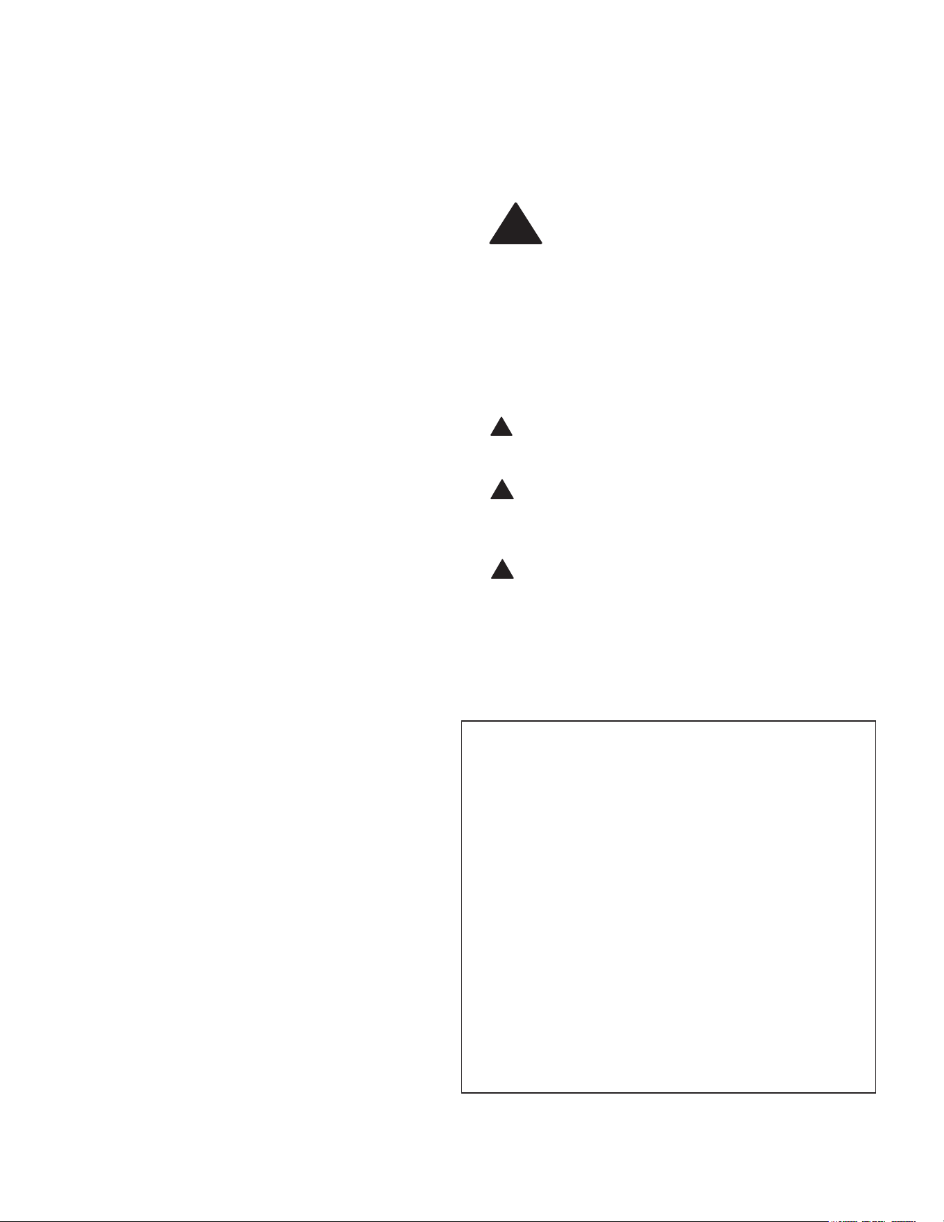
To meet commercial water use needs, the temperature on this water
heater is adjustable up to 185°F (85° C). However, water temperatures
over 125°F (52° C) can cause severe burns instantly or death from
scalds. This is the preferred starting point for setting the control for
supplying general purpose hot water.
Safety and energy conservation are factors to be considered when
setting the water temperature. The most energy efficient operation will
result when the temperature setting is the lowest value that satisfies
the needs consistent with the application.
Maximum water temperatures occur just after burner has shut off. To
find the temperature of the hot water being delivered, turn on a hot
water faucet, and place a thermometer in the hot water stream, and
read the thermometer.
General Safety Precautions
!
The following chart details the relationship of water temperature and
time to scald injury and may be used as a guide in determining the
safest water temperature for your applications.
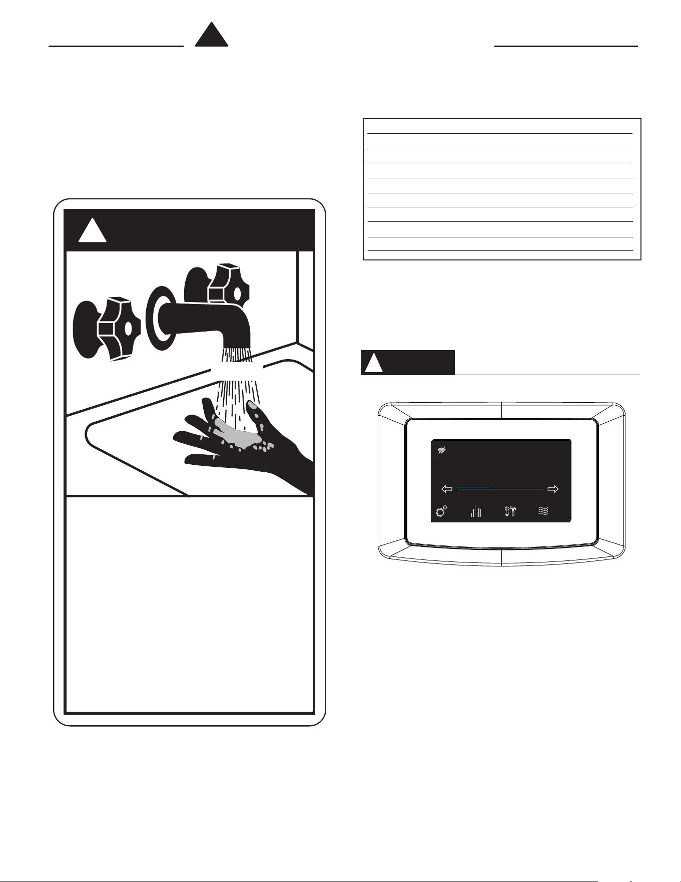
The temperature of the water in the heater can be regulated by
setting the temperature on the display (see pages 34 & 37). To
comply with safety regulations the water heater temperature was
set to 120°F (49°C) before the water heater was shipped from the
factory. The illustration information on pages 34 & 37 shows the dis-
play and how to adjust the water temperature.
Hotter water increases the potential for hot water SCALDS.
NOTICE: Mixing valves are recommended for reducing point of
use water temperature by mixing hot and cold water in branch
water lines. It is recommended that a mixing valve complying
with the Standard for Temperature Actuated Mixing Valves for Hot
Water Distribution Systems, ASSE 1017 be installed. See page 6
for more details. For additional information, contact a licensed
plumber or the local plumbing authority.
!
DANGER
HOT
BURN
BURN
Water temperature over 125°F (52°C)
can cause severe burns instantly or
death from scalds.
Children, disabled and elderly are at
highest risk of being scalded.
See instruction manual before
setting temperature at water heater.
Feel water before bathing or
showering.
Temperature limiting valves are
available, see manual.
Temperature Time to Produce Serious Burn
120° F (49°C) More than 5 minutes
125° F (52°C) 1
1
/
2
to 2 minutes
130° F (54°C) About 30 seconds
135° F (57°C) About 10 seconds
140° F (60°C) Less than 5 seconds
145° F (63°C) Less than 3 seconds
150° F (66°C) About 1
1
/
2
seconds
155° F (68°C) About 1 second
Table courtesy of Shriners Burn Institute
TIME / TEMPERATURE RELATIONSHIPS IN SCALDS
DANGER
!
See Section "User Interface" (pages 33 & 36) for setting the temperature.
Status: Standby
StatusSettings
warm hot very hot
Disable
120°
Service
4
General Safety Precautions
Be sure to read and understand the entire Use & Care Manual before attempting to install or operate this water heater.
Especially the following General Safety Precautions. Failure to follow these warnings could result in a fire or explo-
sion, causing property damage, bodily injury, or death. Should you have any problems understanding the instructions
in this manual, STOP, and get help from a qualified installer, service technician, or gas supplier.
DANGER
!
DANGER
!
Failure to properly vent the water heater to the outdoors as
outlined in the "Venting" section (see pages 8 through 29)
of this manual can result in unsafe operation of the water
heater. To avoid the risk of fire, explosion, or asphyxiation
from carbon monoxide, never operate this water heater
unless it is properly vented and has an adequate air supply
for proper operation. Be sure to inspect the vent system for
proper installation at initial start-up and, at least, annually,
thereafter. Refer to the "Maintenance" section (see page 38)
of this manual for more information regarding vent system
inspections.
Gasoline, as well as other flammable materials
and liquids (which include but are not limited to
adhesives, solvents, paint Thinners, etc.), and the
vapors they produce are extremely dangerous.
DO NOT handle, use, or store gasoline or other
flammable or combustible materials anywhere near
or in the vicinity of a water heater or any other
appliance. Be sure to read and follow the warning
label pictured below and other labels on the water
heater and in this manual. Failure to do so can
result in property damage, bodily injury, or death.
WA RNING
!
DANGER
!
WA RNING
!
LIQUEFIED PETROLEUM MODELS — Propane (LP) gas,
must be used with great caution.
• It is heavier than air and will collect first in lower areas
making it hard to detect at nose level.
•
Make sure to look and smell for LP leaks before attempt-
ing ignition of the water heater. Use a soapy solution to
check all gas fittings and connections. Bubbling at a con-
nection indicates a leak that must be corrected.
• When smelling to detect an LP leak, be sure to sniff near
the floor too.
• Gas detectors are recommended in LP applications and
their installation should be in accordance with the manu-
facturer's recommendations and local laws, rules, regu-
lations, or customs.
• It is recommended that more than one method be used
to detect leaks in LP applications.
IF LP GAS IS PRESENT OR SUSPECTED:
• DO NOT attempt to find the cause yourself;
• DO NOT try to light any appliance;
• DO NOT touch any electrical switch;
• DO NOT use any phone in your building.
• Leave the building immediately and make sure your fam-
ily and pets leave also.
• Leave the doors open for ventilation and contact the gas
supplier, a qualified service agency or the fire depart-
ment.
• Keep the area clear until the service call has been made,
the leak is corrected, and a qualified agency has deter-
mined the area to be safe.
Read and Review this entire
manual with special emphasis on the "Venting" section
(Pages 8-29) and "Operation" section (Pages 32-33) prior to
any installation work.
Gasoline, as well as other flammable materials and liquids
(adhesives, solvents, etc.) and the vapors they produce,
are extremely dangerous. DO NOT handle, use or store
gasoline or other flammable or combustible materials
anywhere near or in the vicinity of a water heater. Be sure
to read and follow the warning label pictured below as
well as the other labels on the water heater, and warnings
printed in this manual. Failure to do so can result in prop-
erty damage, bodily injury, or death.
Both LP and natural gas have an odorant added to help
detection. Some people may not physically be able to
smell or recognize this odorant. If unsure or unfamiliar
about the smell associated with LP or natural gas, ask the
gas supplier. Other conditions, such as "Odorant Fade",
which causes the odorant to "fade" or diminish in
intensity can also hide or camouflage a gas leak.
!
Water heaters utilizing Liquefied Petroleum gas (LP) are
different from natural gas models. A natural gas heater will
not function safely on LP gas and vice versa. No attempt
should ever be made to convert a heater from natural gas
to LP gas. To avoid possible equipment damage, personal
injury or fire: DO NOT connect this water heater to a fuel
type not in accordance with the unit's data plate. Propane
for propane units; natural gas for natural gas units. These
units are not certified for any other type fuel.
LP appliances should not be installed below-grade (for
example, in a basement) if such installation is prohibited by
federal, state, or local laws, rules, regulations or
customs.
WA RNING
!
!
!
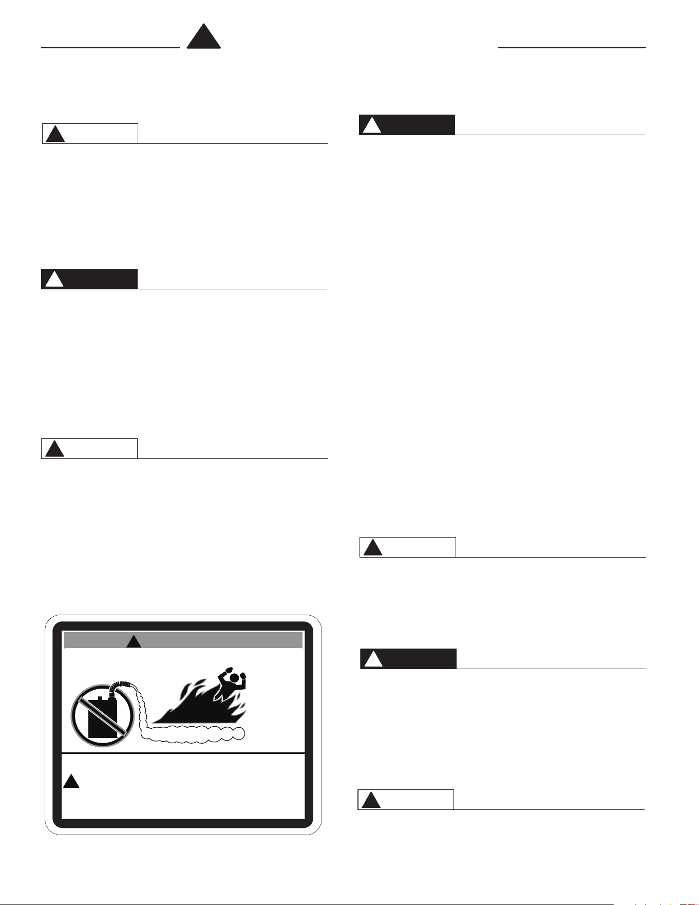
FLAMMABLES
Flammable Vapors
FIRE AND EXPLOSION HAZARD
Can result in serious injury or death.
Do not store or use gasoline or other flammable vapors and liquids
in the vicinity of this or any other appliance. Storage or use of gasoline
or other flammable vapors or liquids in the vicinity of this or any other
appliance can result in serious injury or death.
W ARNING
WA RNING
!
5
LOCAL INSTALLATION REGULATIONS
This water heater must be installed in accordance with
these instructions, local codes, and utility company
requirements. In the absence of local codes, the latest
edition of the National Fuel Gas Code, ANSI Z223.1 in
the United States, or CAN/CSA B149.1
Installation Codes in Canada should be consulted.
LOCATION
A. If this water heater is of the direct vent, all air for
combustion and all products of combustion are
routed through the venting system, directly from the
water heater to the outside of the building.
Otherwise, this unit can also be set up as a power
vent unit. Combustion air for a power vent unit will
be obtained from the surrounding area. Ensure that
there is an adequate air supply for the water heater,
per the codes given above in the "Local Installation
Regulations" section.
The water heater should be installed in a clean, dry
location as close as practical to the vent terminals.
Long hot water lines should be insulated to conserve
water and energy. The water heater and water lines
should be protected from exposure to freezing
temperatures.
B. A gas fired water heater should not be installed in a
space where liquids which give off flammable vapors
are to be used or stored. Such liquids include
gasoline, LP gas (butane and propane), paint or
adhesives and their thinners, solvents or removers.
Because of natural air movement in a room or other
enclosed space, flammable vapors can be carried
some distance from where their liquids are being
used or stored. The open flame of the water heater’s
main burner can ignite these vapors causing an
explosion or fire which may result in severe burns,
death, or property damage. For these reasons, in-
stallation of a gas-fired water heater in a garage is
not desirable.
C. All models are certified for installation on combusti-
ble floors and in alcoves. The minimum side and top
clearance to walls and ceiling for providing
protection of combustible materials are shown on
the water heater’s rating label. A top and front clear-
ance of 24 inches (61 cm) is recommended for in-
spection and servicing. The "Top" clearance is mea-
sured from the top pan of the unit.
NOTICE: Auxiliary catch pan installation MUST
conform to the applicable local codes.
The water heater should not be located in an area where
leakage of the tank or connections will result in damage
to the area adjacent to it or to lower floors of the
structure. When such areas cannot be avoided, it is
recommended that a suitable catch pan be installed
under the water heater and adequately drained. The pan
MUST NOT interfere with the operation of the water
heater and access of the serviceable components.
D. RESTAURANT INSTALLATION: — If the water heater
is to be installed in a restaurant or other location
where NSF International listing is required, this unit
must be sealed to the floor, and other components
must be added utilizing Rheem's UL listed NSF seal
Kit (see kit listing on page 35). A factory designed
sealing kit is available from the distributor or store
where the water heater was purchased. When
installed according to the instructions supplied with
the kit, these heaters will meet the NSF international
requirements.
E. CORROSIVE ATMOSPHERES — The heater should
not be installed near an air supply containing
halogenated hydrocarbons. For example, the air in
beauty shops, dry cleaning establishments, photo
processing labs, and storage areas for liquid and
powdered bleaches or swimming pool chemicals
often contain such hydrocarbons. The air there may
be safe to breathe, but when it passes through a
gas flame, corrosive elements are released that will
shorten the life of any gas burning appliance. Propel-
lants from common spray cans or gas leaks from re-
frigeration equipment are highly corrosive after pass-
ing through a flame. The limited warranty is voided
when failure of the water heater is due to a corrosive
atmosphere. (Refer to the Certificate of Limited
Warranty for complete terms and conditions.)The
manufacturer’s warranty does not cover any damage
or defect caused by installation, attachment, or use
of any special attachment, such as energy saving
devices (other than those authorized by the manu-
facturer) into, onto, or in conjunction with the water
heater. The use of such unauthorized devices may
shorten the life of the water heater and may endan-
ger life and property. The manufacturer disclaims any
responsibility for such loss or injury resulting from
the use of such unauthorized devices.
1. INSPECT SHIPMENT — Check for possible dam-
age that may have occurred during shipping. The
manufacturer’s responsibility ceases upon delivery
of goods to the carrier in good condition. Any claims
for damage, shortage in shipments, or non-delivery
must be filed immediately against the carrier by the
consignee.
One plastic bag is included, contains the Use & Care
Manual, and Warranty.
For GHE80SS/SU and GHE100SS/SU models, one
box is included, containing the fitting plugs, a 3 inch
elbow w/screen, exhaust tee w/condensate trap and
instructions to install the neutralizer.
For GHE119SS/SU models, one box is included,
containing the fitting plugs, a 4 inch elbow w/screen,
exhaust tee w/condensate trap and instructions to
install the neutralizer.
2. THERMAL EXPANSION — Determine if a check valve
exists in the inlet water line. It may have been
installed in the cold water line as a separate back
flow preventer, or it may be part of a pressure
reducing valve, water meter or water softener. A
check valve located in the cold water inlet line can
cause what is referred to as a ”closed water sys-
tem”. A cold water inlet line with no check valve
or back flow prevention device is referred to as an
”open” water system.
As water is heated, it expands in volume and
creates an increase in the pressure within the water
system. This action is referred to as ”thermal
expansion”. In an ”open” water system, expanding
water, which exceeds the capacity of the water
heater, flows back into the city main where the
pressure is easily dissipated.
Introduction
CAUTION
!
6
Installation
A ”closed water system”, however, prevents the
expanding water from flowing back into the main
supply line and the result of ”thermal expansion” can
create a rapid, and dangerous pressure increase in
the water heater and system piping. This rapid pres-
sure increase can quickly reach the safety
setting of the relief valve, causing it to operate
during each heating cycle. Thermal expansion, and
the resulting rapid, repeated expansion and contrac-
tion of components in the water heater and piping
system can cause premature failure of the relief
valve and possibly the heater itself. Replacing the
relief valve will not correct the problem!
The suggested method of controlling thermal
expansion is to install an expansion tank in the cold
water line between the water heater and the check
valve. The expansion tank is designed with an air
cushion built in that compresses as the system
pressure increases, thereby relieving the over pres-
sure condition and eliminating the repeated operation
of the relief valve. Other methods of controlling ther-
mal expansion are also available. Contact your install-
ing contractor, water supplier, or plumbing inspector
for additional information regarding this subject.
If a recirculation line is installed, the return con-
nection should be made through a tee close to the
inlet connection on the water heater. A check valve
should always be installed in the recirculation line to
prevent cold water from entering.
WATER CONNECTIONS — This water heater may be
connected individually, in multiples with others, or
with an external hot water storage tank.
Inlet water connections are made to the lower
coupling on the heater, and outlet water connections
are made to the upper coupling.
Each water heater is supplied with the necessary
components (diffuser tubes) to make the water
connections that will ensure proper performance.
The components are supplied in a bag attached to
the water heater. If special instructions are required
for any specific water heater, they will be included in
the bag.
Cap or plug unused connections. Use only clean,
new galvanized steel, copper or approved plastic
pipe for water connections. Local codes or regula-
tions shall govern the exact type of material to be
used.
The installation of unions on the inlet and outlet
water lines and a shut-off valve in at least the cold
water inlet line is recommended, so the water heater
may be easily disconnected for servicing. Dielectric
unions are not required for protection of the water
heater.
Mixing valves are recommended for reducing point
of use water temperature by mixing hot and cold
water in branch water lines. It is recommended
that a mixing valve complying with the Standard for
Temperature Actuated Mixing Valves for Hot Water
Distribution Systems, ASSE 1017 be installed. See
page 3 for more details and contact a licensed
plumber or the local plumbing authority for further
information.
Thermometer(s) should be installed so that they
indicate the temperature of the water at or near the
outlet of the water heater and storage tank(s) if
provided.
3. RELIEF VALVE — A new factory installed combina-
tion pressure and temperature relief valve, comply-
ing with the Standard for Relief Valves and Auto-
matic Gas Shutoff Devices for Hot Water Supply
Systems, ANSI Z21.22, or Standard CSA 4.4, Tem-
perature, Pressure, Temperature and Pressure Relief
Valves and Vacuum Relief Valves is provided with the
water heater. No valve is to be placed between the
relief valve and the water heater. For a circulating
tank installation, the separate storage tank(s) must
have similar protection. The pressure rating of the
relief valve must not exceed 150 psi (1034 kPa) (160
psi for ASME mod
els), the maximum working pres-
sure as marked on the front of the water heater.
Connect the outlet of the relief valve to a suitable open drain.
The discharge line must pitch downward from the valve to
allow complete draining (by gravity) of the relief valve and
discharge line, and be no smaller than the outlet of the valve.
The end of the discharge line should not be threaded or
concealed and should be protected from freezing. No
valve of any type, restriction or reducer coupling should be
installed in the discharge line. Local codes shall govern the
installation of relief valves.
The Btu/h rating of the relief valve must equal or
exceed the Btu/h input of the water heater as
marked on its rating plate.
4. GAS SUPPLY — The inlet gas pressure to the water
heater must not exceed 10.5" wc (2.6 kPa) for
Natural gas and 13.0" wc (3.2 kPa) for L.P. gas. The
minimum inlet gas pressure (with main burner on)
is shown on the rating plate. Check to see if high
or low gas pressure is present and then contact the
gas company for correction.
The gas line should be of adequate size to prevent
undue pressure drop (pressure should not drop more
than 1.5", when going from standby to full blower
speed condition). Sizing based upon information in
Table 2, on page 31. No additional allowance is nec-
essary for an ordinary number of fittings.
NOTE: The minimum inlet gas pressure (at gas
valve), during ignition to full input, should not be
less than 3.5" WC for Nat. or 11" WC for LP.
A ground joint union and manual shutoff valve
should be installed in the gas line near the water
heater so that the burner assembly may be easily
removed. The shut-off valve must be readily acces-
sible for turning on or off. See Fig. 2.
If a sediment trap is not incorporated as part of the
appliance, a sediment trap shall be installed down-
stream of the equipment shutoff valve as close to
the inlet of the appliance as practical at the time of
the appliance installation. The sediment trap shall be
either a tee fitting with a capped nipple in the
bottom outlet or other device recognized as an
effective sediment trap. See Fig. 2.
WA RNING
!
7
LEAK TESTING — The water heater and its gas
connections MUST be leak tested at normal operat-
ing pressure before it is placed in operation. Turn ON
the manual gas shut-off valve near the water heater.
NOTE: Each water heater should have its
own regulator located a minimum of 8’
from unit.
Use a soapy water solution to test for gas leaks at all
connections and fittings. Bubbles indicate a gas leak
that must be corrected. The water heater factory
connections to the gas valve should also be leak
tested after placing the water heater in operation.
NEVER use open flame to test for gas leaks, as
bodily injury or property damage could result.
PRESSURE TESTING THE GAS SUPPLY SYSTEM —
The water heater and its manual gas shut-off valve
MUST be disconnected from the gas supply piping
system during any high pressure testing of that
system at pressures in excess of 1/2 psi (14” WC.
3.5 kPa).
The water heater MUST be isolated from the gas
piping system by closing the manual gas shut-off
valve during any pressure testing of the gas supply
piping at pressures equal to or less than 1/2 psi (14”
WC / 3.5 kPa).
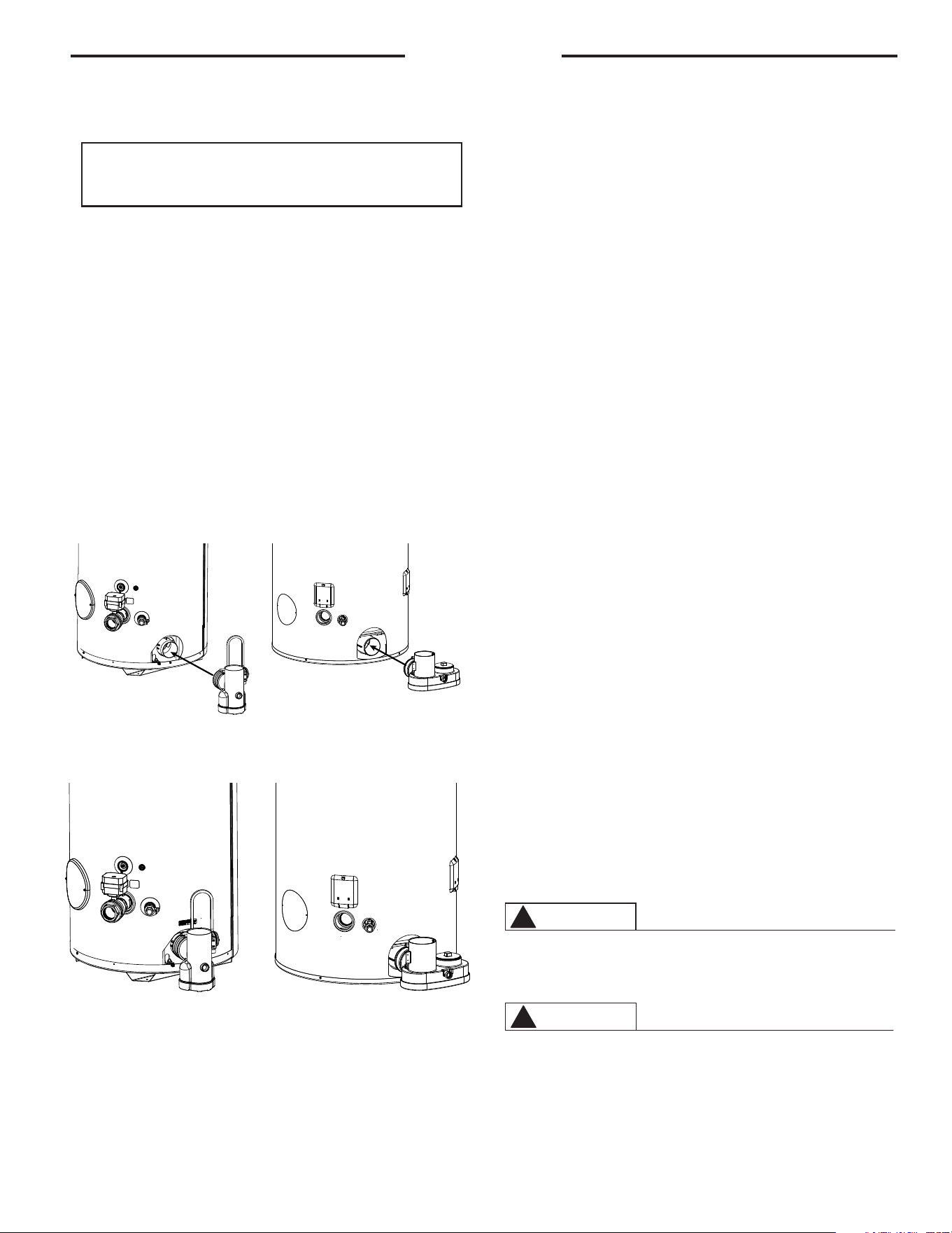
5.
CONDENSATE
EXHAUST TEE & NEUTRALIZER -
The exhaust
elbow/condensate trap is located in the instal-
lation kit along with the bag of neutralizer. Pour
the neutralizer into the exhaust tee so that it is in
the bottom. Then insert the exhaust tee onto the
heater as shown in Figure 1. Using a 5/16" nut
driver or ratchet, tighten the exhaust tee onto the
heater.
CONDENSATE -
This is a condensing high effi-
ciency appliance and has a condensate removal
system. The exhaust tee incorporates a conden-
sate trap and must be filled with water before
operating the water heater. For GHE80SS/SU
and GHE100SS/SU models, pour about 1 cup of
water into the exhaust tee. For GHE119SS/SU
models, pour about 2 cups of water into the ex-
haust tee.
SERVICING -
Remove the exhaust elbow from
the heater using a 5/16" nut driver or ratchet.
Empty the condensate and neutralizer from the
exhaust elbow, and refill it with the new neutral-
izer (Rheem part number AP16770). Re-attach
the exhaust tee to the heater. For GHE80SS/SU
and GHE100SS/SU models, pour about 1 cup
of water into the exhaust tee. For GHE119SS/
SU models, pour about 2 cups of water into the
exhaust tee. into the exhaust tee. Re-attached
the venting
. It is very important that the condensate
line is sloped away from the heater and down to a
suitable inside drain. If the condensate outlet on
this unit is lower than the drain, you must use a con-
densate removal pump. It is also important that the
condensate line is not exposed to freezing tempera-
tures, or any other type of blockage. Plastic tubing
should be the only material used for the condensate
line. Steel, brass, copper, or other metals will be
subject to corrosion and deterioration, so they are
not recommended to be used for the condensate
drain line. A second vent may be necessary to pre-
vent condensate line vacuum lock if a long horizon-
tal run is used. Also an increase to 1" tubing may be
necessary.
6. WIRING — A correct polarity 120V 50/60 Hz power
supply with suitable disconnect means, must be
connected to the black and white leads provided.
The maximum current draw by these models is 7
Amps. The water heater, when installed, must be
electrically grounded in accordance with local codes
or, in the absence of local codes, with the National
Electrical Code, ANSI/NFPA 70 in the United States,
or CSA C22.1 Electrical Code, in Canada. Improper
grounding or polarity may result in abnormal opera-
tion of the unit. Refer on page 49 of this manual for
the wiring diagram for this water heater.
The water heater must be vented to the outdoors
as described in these instructions.
DO NOT connect this water heater to an existing vent or
chimney; it must be vented separately from all other ap-
pliances, using only approved venting materials.
Installation
Figure 1
Figure 2 - Condensate Trap
WA RNING
!
WA RNING
!
Complete installation of wiring harnesses per in-
stallation instructions in kit.
GHE80SS SU and
GHE100SS/SU
GHE80SS SU and
GHE100SS/SU
GHE119SS/SU
GHE119SS/SU
8
Failure to properly vent the water heater to the outdoors as out-
lined above and in the following section can result in unsafe opera-
tion of the water heater causing bodily injury, explosion, fire or
death.
NOTICE: DO NOT use in conjunction with a GFCI.
To
avoid the risk of fire, explosion or asphyxiation from carbon
monoxide, NEVER operate this water heater unless it is properly
vented and has an adequate air supply for proper operation. It
is important that the vent pipe engages fully into any pipe fitting
and be kept in that position until the adhesive has fully cured.
DO NOT drill or punch holes in the plastic pipe or fittings.
7. VENTING —
This water heater must be vented to the outdoors
with a venting system that is certified to the Under-
writer's Laboratories of Canada Standard ULC-S636
(Current Edition). The vent system must be installed
in accordance with the vent system manufacturer's
installation instructions.
NOTE: This unit can be vented either as a direct vent
or power vent configuration.
NOTICE: This unit can be vented using only the below
recommended pipe material. Use only 2, 3, 4, or 6
inch diameter pipe.
Refer to local codes for restrictions on the use of PVC,
CPVC, PP or ABS pipe and fittings. All exhaust venting
materials for products installed in Canada must meet
ULC-S636.
PVC (Schedule 40, ASTM D-1785)
CPVC (Schedule 40, ASTM F-441)
ABS (Schedule 40, ASTM D-2661)(Not permitted in
Canada)
PVC Cellular Core (Schedule 40, ASTM F-891)(Not
permitted in Canada)
The fittings, other than the VENT TERMINAL,
should be equivalent to the following:
PVC (Schedule 40 DWV, ASTM D-2665)
Installation
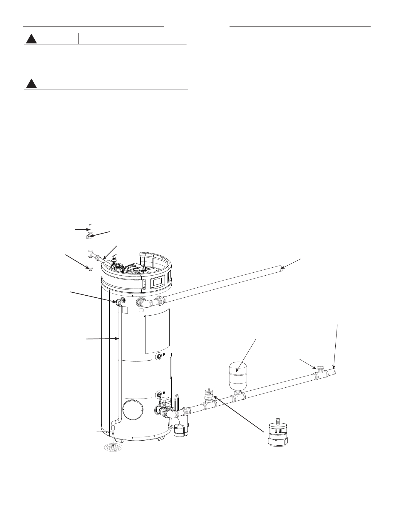
Figure 3. — Typical Installation Drawing.
NOTES:
The gas supply piping must be adequately supported and
aligned to minimize loads (forces) on the water heater’s gas
valve and burner system.
Vacuum Relief Valve
(Not Supplied)
If required, install per local codes
and valve manufacturer’s
instructions.
Temperature &
Pressure Relief
Valve
Air Gap 6"
Hot Outlet
Cold Water
Inlet
Thermal Expansion Tank
(Not Supplied)
If required, install per local codes and
tank manufacturer's instructions.
Shut -Off Valve
To Gas Supply
Manual Gas Shut Off
Gas Pipe to Gas Valve
Sediment Trap
Discharge Line to
suitable open drain
WA RNING
!
WA RNING
!
Vacuum Relief Valve
(Not Supplied)
If required, install per local codes and
valve manufacturer's instructions.
9
CPVC (Schedule 40 DWV, ASTM F-438)
ABS (Schedule 40 DWV, ASTM D-2661)(Not permitted
in Canada)
NOTICE: Use of PVC cellular core (ASTM-F891), ABS
Schedule 40, DWV cellular core (ASTM –F628), or
Radel® (polyphenylsulfone) in non-metallic venting
systems is prohibited.
The unit may be vented horizontally through a wall
or vertically through the roof. Pipe runs must be ad-
equately supported along both vertical and horizontal
runs. Maximum unsupported span is recommended
to be no more than 4 feet. It is imperative that the
first hanger be located on the horizontal run immedi-
ately adjacent to the first 90-degree elbow from the
vertical rise or at the blower outlet, in the case of a
horizontal blower position. The support method used
should isolate the vent pipe from floor joists or other
structural members to help prevent the transmission
of noise and vibration. DO NOT support, pin, or other-
wise secure the venting system in a way that restricts
the normal thermal expansion and contraction of the
chosen venting material.
DO NOT install thermal insulation to the non-metalic
vent pipes and fittings.
If the water heater is being installed as a replacement
for an existing power vented water heater, a thorough
inspection of the existing venting system must be
performed prior to any installation work. Verify that
the correct materials, as detailed above, have been
used and that the minimum or maximum vent length
and terminal locations, as detailed in this manual,
have been met. Carefully inspect the entire venting
system for any signs of cracks or fractures, particu-
larly at the joints between elbows or other fittings and
the straight runs of vent pipe. Check the system for
signs of sagging or other stresses in the joints as a
result of misalignment of any components in the sys-
tem. If any of these conditions are found, they must
be corrected in accordance with the venting instruc-
tions in this manual before completing the installation
and putting the water heater into service.
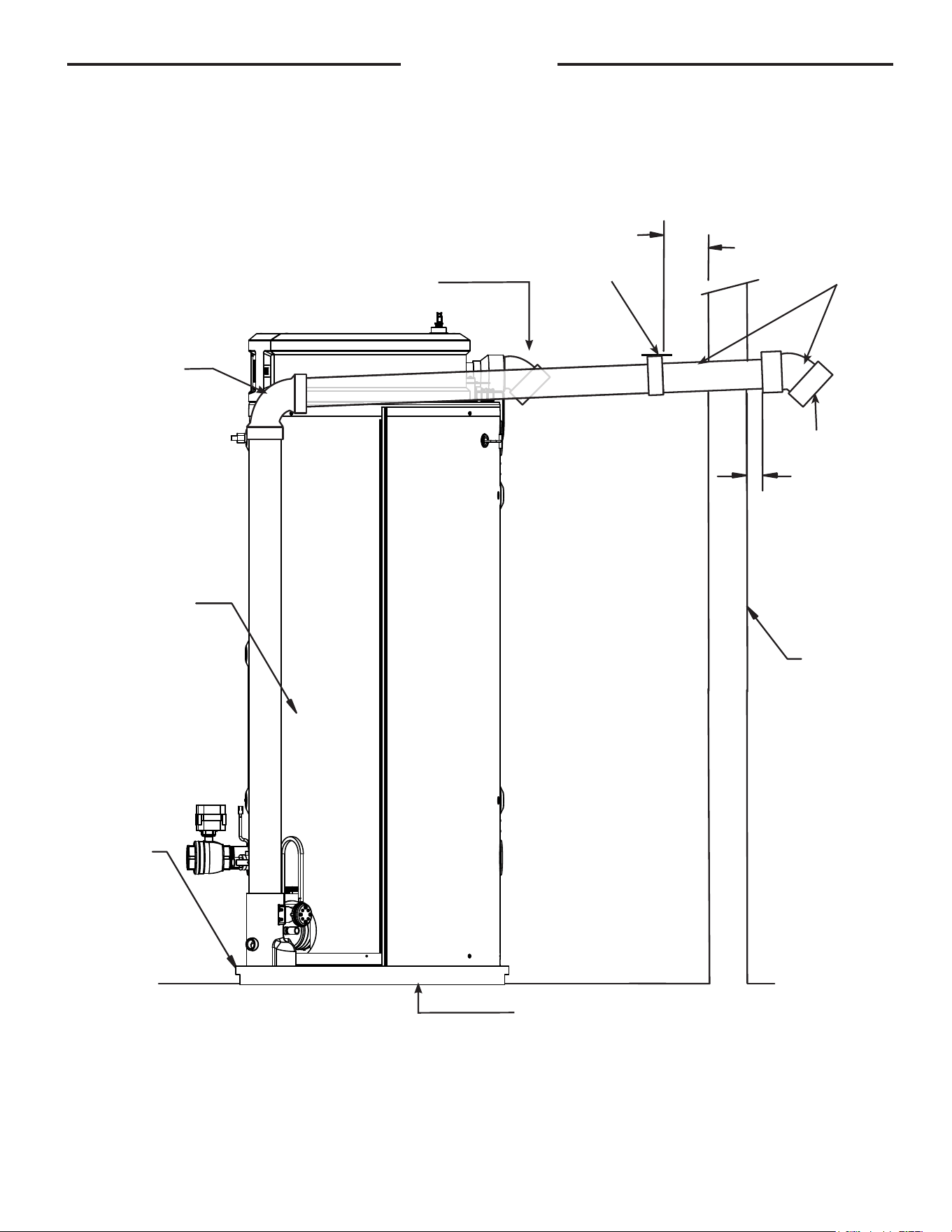
VENT PIPE CONNECTION —
Note: It is recommended that a suitable rubber coupling
is used on the outlet vent connection.
Refer to Figure 4, for connecting the vent pipe to the
water heater. These models can be vented either as a
direct vent or as a power vent water heater.
NOTICE: If the unit is installed as a power vent water
heater, the vent terminal with screen must still be
installed on the inlet air side.
Before starting the vent installation, careful planning
should be given to the routing and termination of the
vent pipes. The length of the vent pipes (inlet and out-
let) should be kept to a minimum. Also, see Figures 9
& 10 for vent terminal placement. Refer to the venting
charts in Table 1 for the pipe sizes and the total equiv-
alent length of pipe that can be used. DO NOT exceed
the equivalent length of pipe in the charts.
Depending on the size of pipe selected for venting
the water heater, it may be necessary to use a fitting
for stepping up or down in pipe size to connect to
the water heater. All models are shipped with 3" vent
terminals with screen. If another size of pipe is used
for venting the unit, the proper vent terminal must be
installed.
When the unit is vented as a direct vent, through a
side wall, the vent terminals must be on the same
exterior wall mounted horizontally and maintain a
minimum distance between the centers of 24" (61 cm).
See Figures 6, 7, and 8 for other vent terminal restric-
tions.
JOINING PIPES AND FITTINGS – All pipe, fittings,
solvent cement, primers, and procedures, must con-
form to American National Standards Institute and
American Society for Testing and Materials (ANSI/
ASTM) standards in the U.S. For Canada, all pipe, fit-
tings, solvent cement, primers, and procedures must
conform to ULC-S636 and vent manufacture specifi-
cations.
CEMENTING JOINTS – All joints in the vent piping
must be properly sealed. Use of the following material
is recommended:
PVC materials should use ASTM D-2564 grade
cement.
CPVC materials should use ASTM F-493 grade
cement.
ABS materials should use ASTM D-2235 grade
cement.
(ABS is not allowed in Canada)
Cleaner-Primer and Medium Body Solvent Cement
1. Cut the pipe end square, removing all jagged edges
and burrs. Chamfer the end of the pipe, and, then,
clean the fitting socket and pipe joint area to remove
all dirt, grease, and moisture.
2. After checking pipe and socket for proper fit, wipe the
socket and pipe with cleaner-primer. Apply a liberal
coat of primer to the inside surface of the socket and
the outside of the pipe. DO NOT allow the primer to
dry before applying the cement.
3. Apply a thin coat of cement evenly in the socket.
Quickly apply a heavy coat to the pipe end. Insert the
pipe into the fitting with a slight twisting motion until it
bottoms out.
NOTICE: Cement must be fluid; if not, re-coat.
4. Hold the pipe fitting for 30 seconds to prevent the ta-
pered socket from pushing the pipe out of the fitting.
5. Wipe all excess cement from the joint with a rag.
Allow 15 minutes for drying before handling. Cure time
will vary according to fit, temperature, and humidity.
NOTICE: Stir the solvent cement frequently while using.
Use a natural bristle brush or the dauber supplied with
the can. The proper brush size is one inch.
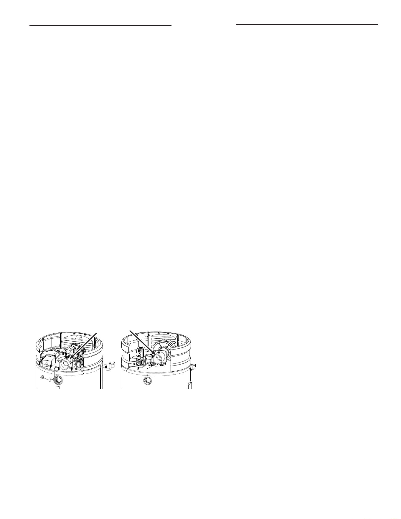
Installation
Figure 4.
—
Vent Pipe Connection Locations
Air Inlet
Connection
GHE80SS SU and
GHE100SS/SU
GHE119SS/SU
10
FOR PROPER INSTALLATION:
CAUTION
!
• DO NOT use solvent cement that has become
curdled, lumpy or thickened.
• DO NOT thin solvent cement. Observe shelf
precautions printed on the containers.
• For applications below 32°F (0°C), use only low
temperature type solvent cement.
• Appropriate solvent and cleaner must be used
for the type of vent pipe used (PVC, CPVC, PP,
or ABS).
DANGER OF FIRE OR BODILY INJURY – Solvent
cements and primers are highly flammable. Provide
adequate ventilation and DO NOT assemble near a
heat source or open flame. DO NOT smoke. Avoid
skin or eye contact. Observe all cautions and warn-
ings on material containers.
DIRECT VENT INSTALLATION - Check to make sure
flue gases DO NOT recirculate into the air intake
terminal when using direct venting. If the water heat-
er is having service issues, flue recirculation may be
a contributing factor. Even when the minimum vent
terminal separation distances are followed,
recirculation may still occur, depending upon the
location outside the building, the distance from other
buildings, proximity to corners, weather conditions,
wind patterns, and snow depth. Periodically check
to make sure that flue recirculation is not occur-
ring. Signs of flue gas recirculation include frosted
or frozen intake terminals, condensate in the intake
terminal and venting system, oxidation, or white
chalk material on the flame sensor or igniter shield.
Correction to flue recirculation may involve angling
the intake away from the exhaust terminal, increas-
ing the distance between them, or using inside air
for combustion. Check to be sure the intake and ex-
haust terminals are not obstructed, especially during
periods of below freezing weather.
All intake and exhaust venting components must
have the same diameter size. DO NOT use a different
size on the intake and exhaust venting.
Be sure the condensate runs freely to a drain and
does not accumulate inside the water heater. In cold
climates, precautions may need to be taken to insure
that the condensate drain does not freeze. Make
sure the condensate trap or drain loop is installed to
prevent flue gases from being discharged into the
room. Refer to the "Venting" section (page 8), "Con-
densate" section (page 7) of this manual for com-
plete instructions on venting and condensate drain-
age.
Stress levels in the pipe and fittings can be
significantly increased by improper installation. If
rigid pipe clamps are used to hold the pipe in place,
or if the pipe cannot move freely through a wall
penetration, the pipe may be directly stressed, or
high thermal stresses may be formed when the pipe
heats up and expands. Install accordingly to mini-
mize such stresses. Follow the below procedure to
vent through the wall.
1. Cut two holes for the pipe to pass through. The hole
diameter should be 2.5" (6.4 cm) for 2" pipe, 3.5"
(8.9 cm) for 3" pipe, and 6.5" (16.5 cm) for 6" pipe.
Vent terminals must maintain a horizontal distance
apart in the range of 24" to 36" (61 cm to 91 cm).
Refer to Figure 5 for additional information.
2. Use the proper PVC cement (primer and adhesive)
to secure the exhaust vent and air intake terminals
provided with the water heater to the plastic pipes.
The distance between the back edge of the exhaust
vent terminal and the exterior wall (see Figure 10)
must be 6 inches (12.7 cm) more for the exhaust vent
terminal than the air intake terminal. Use the
proper cement or sealant and assembly procedures to
secure the vent connector joints between the
terminal and the blower outlet. Provide support
brackets for every 3 feet (.91 m) of horizontal vent
beyond the intake terminal as seen in Figure 11.
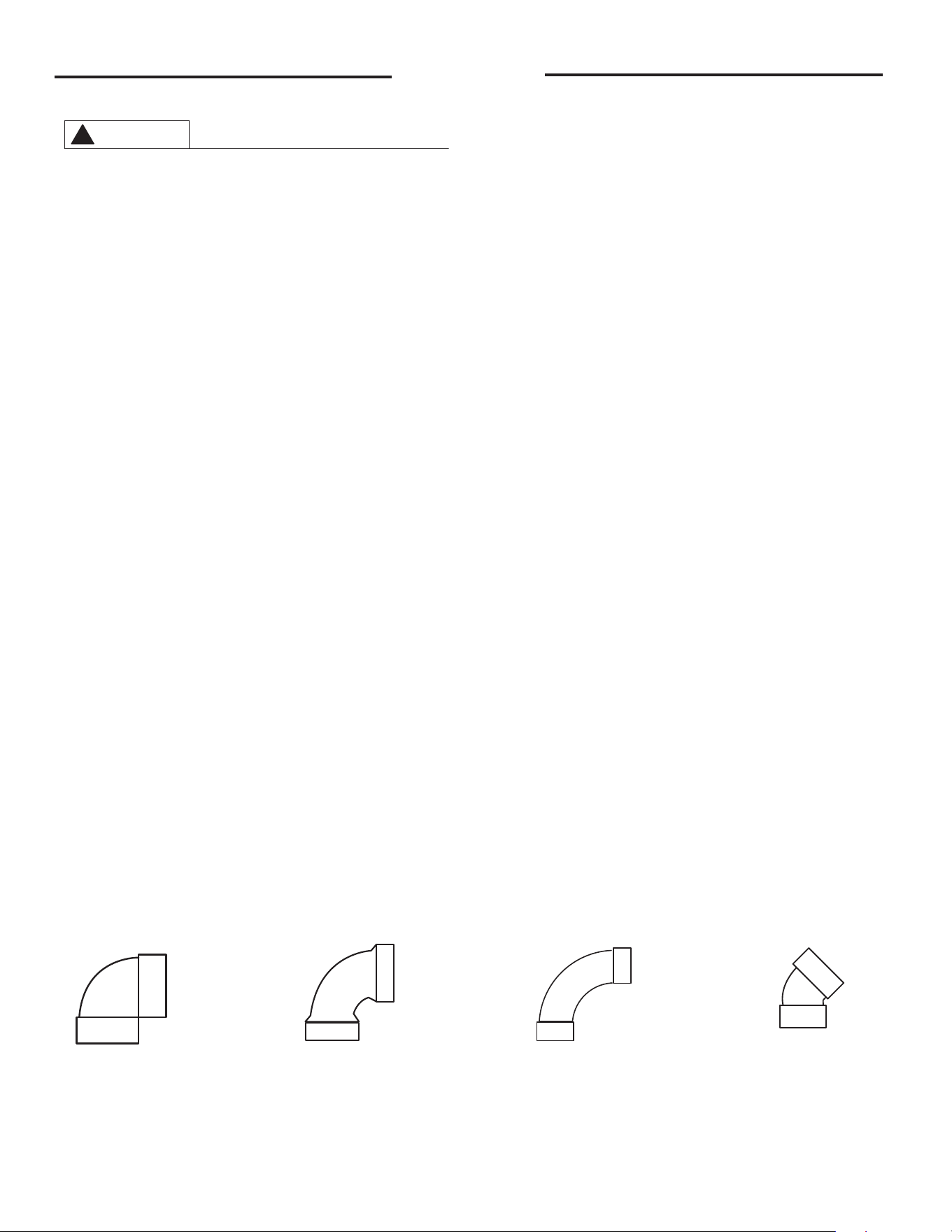
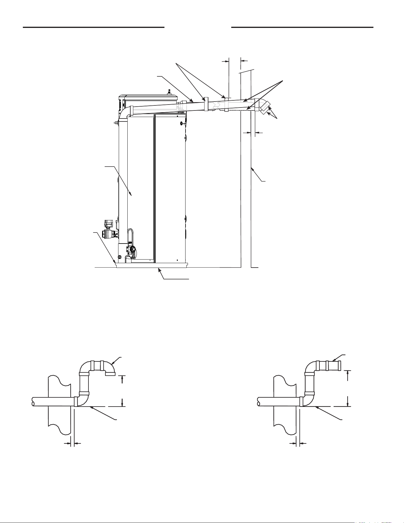
Additional Fitting Considerations
Short Sweep
90° Elbow
Standard Sweep
90° Elbow
Long Radius Sweep
90° Elbow
Standard
45° Elbow
10'
Straight Equivalent
8'
Straight Equivalent
5'
Straight Equivalent
2.5'
Straight Equivalent
Figure - 5. Examples of Elbows:
DO NOT RECOMMEND short sweep elbows. It is recommended to use only standard and/or long sweep elbows.
See examples as shown.
Installation
11
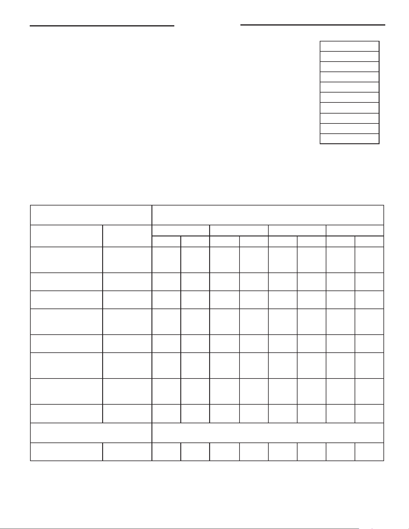
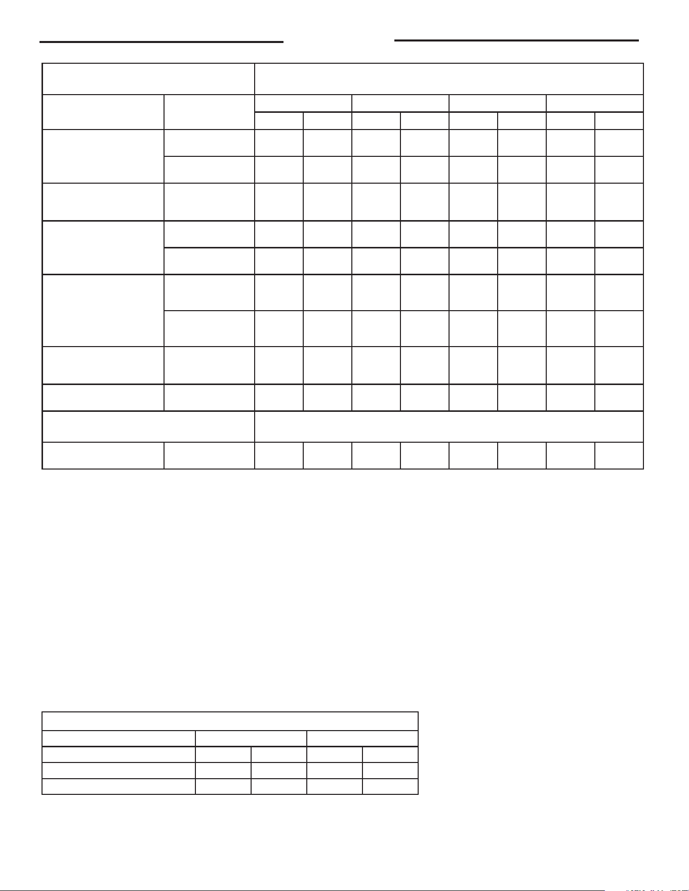
TABLE 1. POWER VENTING – RIGID VENT PIPING: PVC, CPVC, ABS, PP – MAX VENT LENGTHS
Models GHE80SU-200(A) & GHE80SU-300(A) are limited to an altitude of 8000 ft, while all other models are limited to
8999 ft.
Model GHE119SU-500(A) if installed above 5000 ft, refer to "Gas Valve Instructions" for adjustments.
MINIMUM AND MAXIMUM VENT LENGTHS
Important information for all installations:
1) The minimum required venting is what is required to safely extend the
inlet and outlet vent pipes outside of the building.
2)
Each 90° elbow (standard or long sweep elbow) reduces the
equivalent vent length by 5 feet (1.5m).
3) Each 45° elbow reduces the equivalent vent length by 2 1/2 feet
(0.8m).
4) DO NOT mix pipe sizes for venting these models, use only one size of
pipe for all venting.
5) All vent terminations (horizontal or vertical) should be a minimum
of 24 inches (61cm) and a maximum of 36 inches (91 cm) apart, as
measured from center to center of terminals.
6) The maximum equivalent vent lengths, for inlet and outlet, must
be within 20 equivalent feet (6.1m) of each other. Supplied vent
terminal(s) are not included in the maximum equivalent vent length.
Exceeding the maximum equivalent vent lengths may cause the water heater to malfunction or
cause a lock-out condition.
Installation
Feet to Meters
20 6.1
50 15.2
60 18.3
70 21.3
80 24.4
100 30.5
120 36.6
130 39.6
170 51.8
Power Vent
Max Vent Length (Eq.Ft.)
Rigid Pipe Diameter
Inlet Models
Altitude
Range
2" (5 cm) 3" (8 cm) 4" (10 cm) 6" (15 cm)
Inlet Outlet Inlet Outlet Inlet Outlet Inlet Outlet
GHE80SU-130(A)
or
GHE80SU-160(A)
0-8999 Ft
(0-2743 m)
1
(0.31 m)
20
(6.1 m)
1
(0.31 m)
135
(41.1 m)
1
(0.31 m)
185
(56.4 m)
N/A N/A
GHE80SU-200(A)
0-8000 ft
(0-2438 m)
N/A N/A
1
(0.31 m)
135
(41.1 m)
1
(0.31 m)
185
(56.4 m)
N/A N/A
GHE80SU-300(A)
0-8000 Ft
(0-2438 m)
N/A N/A
1
(0.31 m)
135
(41.1 m)
1
(0.31 m)
185
(56.4 m)
1
(0.31 m)
120
(36.6 m)
GHE100SU-130(A)
or
GHE100SU-160(A)
0-8999 ft
(0-2743 m)
1
(0.31 m)
20
(6.1 m)
1
(0.31 m)
135
(41.1 m)
1
(0.31 m)
185
(56.4 m)
N/A N/A
GH100SU-200(A)
0-8999 ft
(0-2743 m)
N/A N/A
1
(0.31 m)
135
(41.1 m)
1
(0.31 m)
185
(56.4 m)
N/A N/A
GHE100SU-250(A)
or
GHE100SU-300(A)
0-8999 ft
(0-2743 m)
N/A N/A
1
(0.31 m)
135
(41.1 m)
1
(0.31 m)
185
(56.4 m)
1
(0.31 m)
120
(36.6 m)
GHE100SU-350(A)
or
GHE100SU-400(A)
0-8999 ft
(0-2743 m)
N/A N/A
1
(0.31 m)
65
(19.8 m)
1
(0.31 m)
100
(30.5 m)
1
(0.31 m)
135
(41.1 m)
GHE119SU-500(A)
0-10000 ft
(0-3435 m)
N/A
N/A
1
(0.31 m)
60
(18.3 m)
1
(0.31 m)
150
(46.7 m)
1
(0.31 m)
150
(46.7 m)
Min Vent Length (Eq.Ft.)
Rigid Pipe Diameter
All Models
See Below
1
(0.31 m)
15
(4.6 m)
1
(0.31 m)
15
(4.6 m)
1
(0.31 m)
15
(4.6 m)
1
(0.31 m)
15
(4.6 m)
12
Installation
Venting Configurations are the Same for SS Models:
3 inch concentric vent can only be used with 3 inch rigid piping.
4 inch concentric vent can only be used with 4 inch rigid piping.
DO NOT mismatch concentric vent terminations with different rigid piping as it may cause the heater to mal-
function or cause a lock-out condition.
DO NOT use 2 inch rigid venting with concentric vent terminations.
DO NOT use 6 inch rigid venting with concentric vent terminations.
Note: For Horizontal Power Direct Vent configurations, GHE119SS/SU models will need to have a 45 degree elbow
on the intake and a 90 degree elbow on the exhaust, if they are on the same plane.
Flexible Polypropylene pipe (ft)
Pipe Size (IN.) 3 4
Max PV Intake Exhaust Intake Exhaust
GHE80 and GHE 100 Models 0 60 0 60
GHE119-500 N/A N/A 0 80
Power Direct Vent
Max Vent Length (Eq.Ft.)
Rigid Pipe Diameter
Inlet Models
Altitude
Range
2" (5 cm) 3" (8 cm) 4" (10 cm) 6" (15 cm)
Inlet Outlet Inlet Outlet Inlet Outlet Inlet Outlet
GHE80SU-130(A)
or
GHE80SU-160(A)
0-2000
(0 - 609 m)
20
(6.1 m)
20
(6.1 m)
60
(18.3 m)
75
(22.9 m)
120
(36.6 m)
135
(41.1 m)
N/A N/A
2001-8999
(610 - 2743 m)
20
(6.1 m)
20
(6.1 m)
40
(12.2 m)
55
(16.8 m)
120
(36.6 m)
135
(41.1 m)
N/A N/A
GH80SU-200(A)
or
GHE80SU-300(A)
0-8000 ft
(0-2438 m)
N/A N/A
60
(18.3 m)
75
(22.9 m)
120
(36.6 m)
135
(41.1 m)
120
(36.6 m)
135
(41.1 m)
GHE100SU-130(A)
or
GHE100SU-160(A)
0-2000
(0 - 609 m)
20
(6.1 m)
20
(6.1 m)
60
(18.3 m)
75
(22.9 m)
120
(36.6 m)
135
(41.1 m)
N/A N/A
2001-8999
(610 - 2743 m)
20
(6.1 m)
35
(10.7 m)
40
(12.2 m)
55
(16.8 m)
120
(36.6 m)
135
(41.1 m)
N/A N/A
GH100SU-200(A)
or
GHE100SU-250(A)
or
GHE100SU-300(A)
0-2000
(0 - 609 m)
N/A N/A
60
(18.3 m)
75
(22.9 m)
120
(36.6 m)
135
(41.1 m)
N/A N/A
2001-8999
(610 - 2743 m)
N/A N/A
40
(12.2 m)
55
(16.8 m)
120
(36.6 m)
135
(41.1 m)
120
(36.6 m)
135
(41.1 m)
GHE100SU-350(A)
or
GHE100SU-400(A)
0-8999 ft
(0 - 2743 m)
N/A N/A
50
(15.2 m)
65
(19.8 m)
70
(21.4 m)
85
(25.9 m)
120
(36.6 m)
135
(41.1 m)
GHE119SU-500(A)
0-10000 ft
(0-3435 m)
N/A N/A
60
(18.3 m)
60
(18.3 m)
120
(36.6 m)
130
(39.6 m)
120
(36.6 m)
130
(39.6 m)
Min Vent Length (Eq.Ft.)
Rigid Pipe Diameter
All Models See Below
5
(1.5 m)
15
(15.2 m)
5
(1.5 m)
15
(15.2 m)
5
(1.5 m)
15
(15.2 m)
5
(1.5 m)
15
(15.2 m
TABLE 2. POWER DIRECT VENTING LENGTHS
Models GHE80SU-200(A) & GHE80SU-300(A) are limited to an altitude of 8000 ft, while all other models are limited to 8999 ft.
Model GHE119SU-500(A) if installed above 5000 ft, refer to "Gas Valve Instructions" for adjustments.
Models GHE80SU-200(A) & GHE80SU-300(A) are limited to an altitude of 8000 ft, while all other models are limited to 8999 ft.
NOTE: Units naturally de-rate as vent length is extended from minimum vent. De-rate also occurs when
reducing the diameter of the vent from the default size (GHE80/100 default is 3", GHE119 default is 4").
For each 90° Elbow, reduce pipe length by five (5) feet.
For each 45° Elbow, reduce pipe length by two and a half (2.5) feet.
Note: Vent pipe size should not be mixed for venting these units.
Use same diameter pipe for all venting of the unit.
13
vent terminal is at least 2 feet (0.61 m) away from any-
thing that can be damaged by the condensate
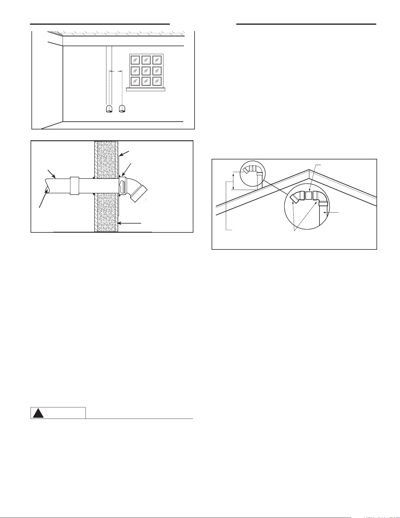
HORIZONTAL VENT INSTALLATION – Once the vent terminal
location has been determined, make a hole through the
exterior wall to accommodate the vent pipe. The vent
pipe must exit the exterior wall horizontally only (See
Figure 7).
Insert a small length of vent pipe through the wall, and
connect the coupling as shown in Figure 7. Connect the
vent terminal as shown to the vent pipe on the exterior
of the building. Seal any opening around the vent pipe or
fittings with mortar or silicone caulk as shown in Figure
7.
Complete the rest of the vent pipe installation to the
water heater’s vent connector fitting on the blower
outlet. If necessary, support the horizontal run
of pipe
as previously mentioned.
Min. 24"
Max. 36"
Inlet Outlet
Additional Considerations (See Figures 9 & 10)
1. DO NOT install vent terminals under any patio or deck.
2. To help prevent moisture from freezing on walls and
under eaves, DO NOT locate outlet vent terminal on
the side of a build ing with prevailing winter winds.
3. DO NOT terminate vent pipe directly on brick or
masonry surfaces. Use a rust-resistant sheet metal
backing plate behind vent. (See Figure 7.)
4. DO NOT locate vent terminal too close to shrubbery,
since flue gases may damage them.
5. Caulk all cracks, seams and joints within 6 feet
(1.83 m) of vent terminal.
6. All painted surfaces should be primed to lessen the
chance of physical damage. Painted surfaces will
require maintenance.
7. Make sure that all vent pipes exposed to cold
conditions (attics, crawl spaces, etc.) have the
proper slope and support to keep moisture from
accumulating in the vent pipes. NOTE: Insulating of
non-metallic vent materials is prohibited.
8. This water heater requires its own separate
venting system. DO NOT connect the exhaust vent to an
existing vent pipe or chimney.
WA RNING
!
Moisture in the flue gas will condense as it leaves the
vent terminal. In cold weather this condensate can
freeze on the exterior wall, under the eaves, and on
surrounding objects. Some discoloration to the
exterior of the building is to be expected; however,
improper location or installation can result in severe
damage to the structure or exterior finish of the
building. In locations with extended amounts of time
with temperatures under 40°F. (4°C.) and/or prevailing
wind toward the outlet vent, make sure that the outlet
VERTICAL VENT INSTALLATION – Once the vent
terminal location has been determined, make a
hole through the roof and interior ceiling to
accommodate the vent pipe. Complete the vent
pipe installation to the water heater’s vent
connector fitting on the blower outlet. Support
vertical or horizontal runs as previously
mentioned.
Install adequate flashing where the vent pipe
passes through the roof. Determine the vent
terminal height and cut the vent pipe accordingly.
Refer to Figure 8 for the proper vent terminal
height. Connect the vent elbow onto the verti-
cal pipe through the roof. Connect a short piece
of vent pipe (approximately 3
" (7.6 cm)
long) to
the elbow, and, then, join the vent terminal to the
short piece of vent pipe.
VERTICAL VENT TERMINAL LOCATION – The location
of the vertical vent terminal depends on the following
considerations (see Figure 8):
1. Minimum 12" (30.5 cm) above the roof 18" (46 cm) for
Canada.
2. Minimum 12" (30.5 cm) inches above anticipated
snow level.
3. Maximum 24" (61 cm) above roof level without addi-
tional support for vent pipe.
4. 4 feet (1.22 m) from any gable, dormer or other roof
structure with building interior access (i.e., vent, win-
dow, etc.).
5. 10 feet (3.05 m) from any forced air inlet to the build-
ing. Any fresh or make-up air inlet such as a dryer or
furnace area is considered to be a forced air inlet.
6. Vent terminals are a minimum of 24" (61 cm) and a
maximum of 36" horizontally apart.
Installation
Figure 7 – Typical Horizontal Vent Installation
Figure 8 – Vertical Vent Terminal Location
Short Piece of Vent
Pipe
*Min. 12"(30.5 CM) Above
Roof or
Min. 12"(30.5 CM) Above
Anticipated Snow Level.
Max. 24"(61 cm) Above
Roof (Without Additional
Support)
Vent Pipe
Through Roof
Elbows
* Min of 18"(46cm) for Canada
Figure 6
Pipe &
Coupling
Sheet Metal Shield on
Brick or Masonry Walls
Outside of the
Building Wall
To the Water Heater
Vent Pipe
Inlet Vent Terminal
with
1
/
2
" Mesh Pro-
tective
Screen Inside
Vent
Pipe
Elbow can be a maximum
of 1 inch from the wall.
14
Installation
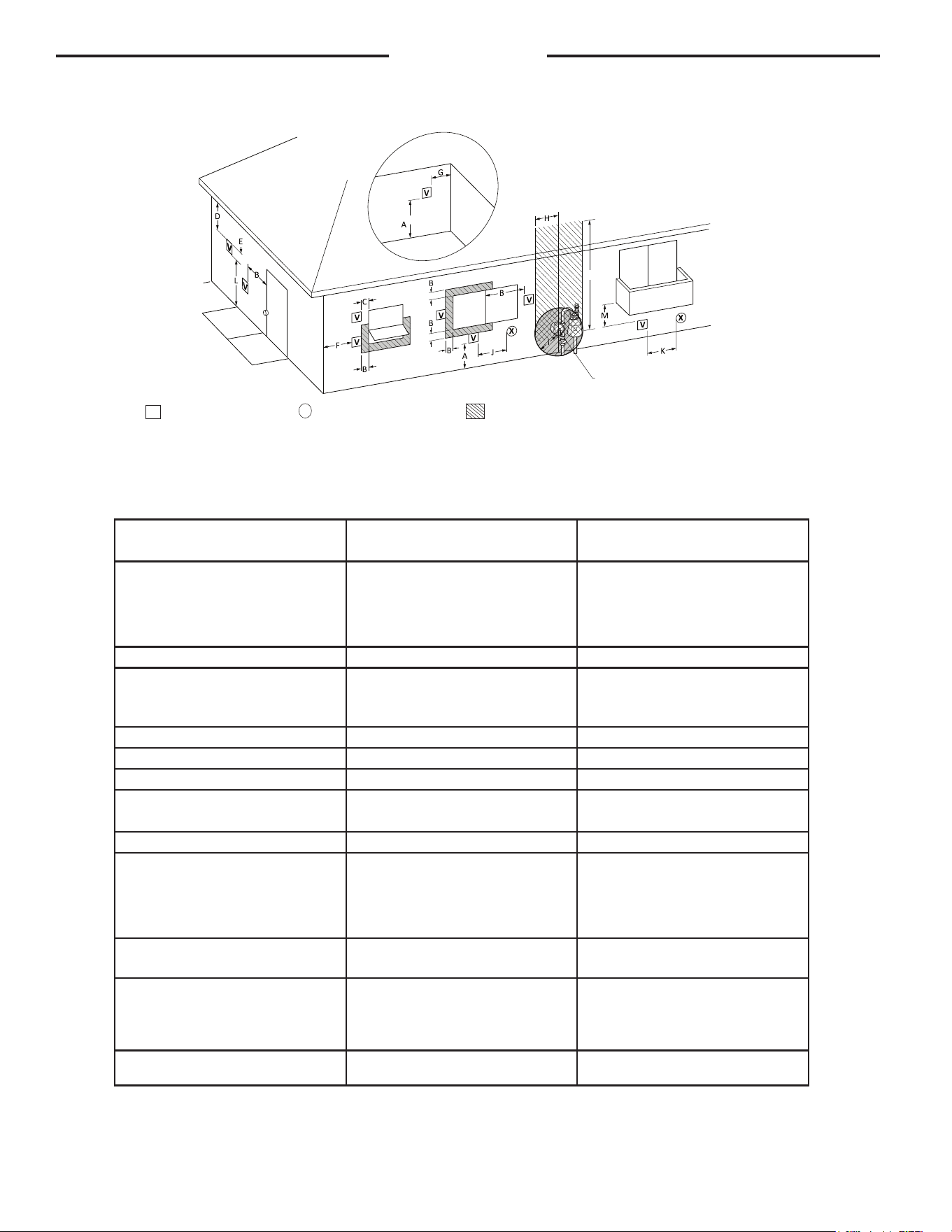
Figure 9
Regulator vent outlet in the event no
regulator is present, H and I can be
disregarded.
Fixed
closed
15 ft
Fixed
closed
Inside
corner detail
Operable
Operable
Horizontal Vent Terminal Location for Power Direct Vent
The following information should be used for determining the proper location of the vent terminal for
direct vent water heaters.
V
VENT TERMINAL
X
AIR SUPPLY INLET
AREA WHERE TERMINAL IS NOT PERMITTED
Canadian Installations
1
US Installations
2
1 In accordance with the current CSA B149.1, Natural Gas and Propane Installation Code
2 In accordance with the current ANSI Z223.1/ NFPA 54 National Fuel Gas Code.
‡ Permitted only if veranda, porch, deck, or balcony is fully open on a minimum of two sides beneath the oor.
* Permitted only if veranda porch, deck, or balcony is fully open on a minimum of two sides beneath the oor.
A= Clearance above grade, veranda, porch, deck
or balcony.
12 inches (30 cm) 12 inches (30 cm)
B= Clearance to window or door that may be
opened.
• 6 in (15 cm) for appliances ≤ 10,000 Btuh
(3 kW),
• 12 in (30 cm) for appliances > 10,000 Btuh
(3 kW) and ≤ 100,000 Btuh (30 kW),
• 36 in (91 cm) for appliances > 100,000 Btuh
(30 kW)
• 6 in (15 cm) for appliances ≤ 10,000 Btuh
(3 kW),
• 9 in (23 cm) for appliances > 10,000 Btuh
(3 kW) and ≤ 50,000 Btuh (15 kW),
• 12 in (30 cm) for appliances > 50,000 Btuh
(15 kW)
C= Clearance to permanently closed window.
0 in (0 cm) 0 in (0 cm)
D= Vertical Clearance to ventilated soffit located
above the terminal within a horizontal dis-
tance of 2 feet (61 cm) from the center line of
the terminal.
12 in (30 cm) 12 in (30 cm)
E= Clearance to unventilated soffit. 12 in (30 cm) 12 in (30 cm)
F= Clearance to outside corner. 24 in (61 cm) 24 in (61 cm)
G= Clearance to inside corner. 18 in (46 cm) 18 in (46 cm)
H = Clearance to each side of center line extend-
ed meter/regulator assembly. above
3 feet (91 cm) within a height 15 feet (4.6 m) 3 ft (91 cm) within a height of 15 ft (4.6 m)
I = Clearance to service regulator vent outlet. 3 feet (91 cm) 3 feet (91 cm)
J = Clearance to nonmechanical air supply inlet
to building or the combustion air inlet to any
other appliance..
• 6 in (15 cm) for appliances ≤ 10,000 Btuh
(3 kW),
• 12 in (30 cm) for appliances > 10,000 Btuh
(3 kW) and ≤ 100,000 Btuh (30 kW),
• 36 in (91 cm) for appliances > 100,000 Btuh
(30 kW)
• 6 in (15 cm) for appliances ≤ 10,000 Btuh
(3 kW),
• 9 in (23 cm) for appliances > 10,000 Btuh
(3 kW) and ≤ 50,000 Btuh (15 kW),
• 12 in (30 cm) for appliances > 50,000 Btuh
(15 kW)
K = Clearance to mechanical air supply inlet.
6 feet (1.83 m)
3 feet (91 cm) above if within 10 feet (3 m) hori-
zontally.
L = Clearance above paved side walk or paved
driveway located on public property.
7 feet (2.13 m)
7 feet (2.13 m) for mechanical draft system (Cat-
egory I appliances); vents for Category II and IV
appliances cannot be located above public walk-
ways or other areas where condensate or vapor
can cause a nuisance or hazard.
M = Clearance under veranda, porch, deck or
balcony.
12 in (30 cm) ‡
12 in (30 cm)*

15
VENT INSTALLATION – Before proceeding, make
certain you understand the procedure and cautions
covered in the section “Joining Pipes and Fittings.”
POWER VENT INSTALLATION:
Power venting is where the indoor air is used and
the exhaust is vented to the outside. Venting may be
run horizontally through an outside wall or vertically
through a roof through using either 2" (5.1 cm), 3"
(7.6 cm), 4" (10.2 cm) or 6" (15.2 cm) diameter PVC,
ABS or CPVC. This water heater is supplied with a
screened intake elbow and exhaust coupling referred
to as the air intake terminal and the exhaust vent
terminal.
NOTE:
Flexible PP vent kit is available for Power Vent con-
figurations, in either 3" or 4" diameters. These kits
should be used for vertical venting only.
NOTICE: Use of PVC cellular core (ASTM-F891),
ABS Schedule 40, DWV cellular core (ASTM –F628),
or Radel® (polyphenylsulfone) in non-metallic
venting systems is prohibited.
In a horizontal application, it is important that
condensate not be allowed to buildup in the exhaust
vent pipe. To prevent this from happening, the pipe
should be installed with a slight upward slope of ¼”
per foot. The vent system must be supported every 5
feet of vertical run and every 3 feet of horizontal run
of vent pipe length.
Failure to properly support the vent piping with
hangers and clamps may result in damage to the
water heater or venting system.
Installation
• DO NOT terminate near soffit vents or crawl space or other area where condensate or vapor could create a nuisance
hazard or cause property damage.
• DO NOT locate the exhaust vent terminal where condensate or vapor could cause damage or could be detrimental to
the operation of regulators, relief valves, or other equipment.
• DO NOT locate the exhaust vent terminal over public area or walkways where condensate or vapor can cause nui-
sance or hazard.
• DO NOT locate the vent terminal in proximity to plants/shrubs.
16
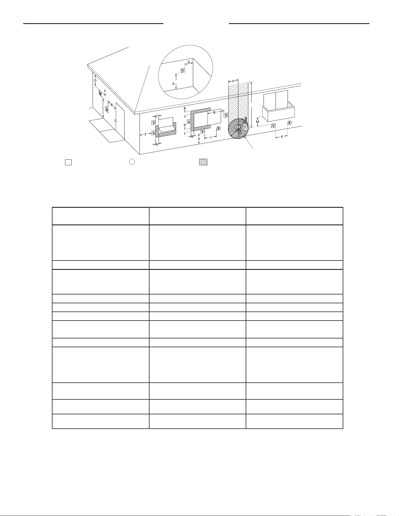
Figure 10
Installation
Regulator vent outlet in the event no
regulator is present, H and I can be
disregarded.
Fixed
closed
15 ft
Fixed
closed
Inside
corner detail
Operable
Operable
Horizontal Vent Terminal Location for Power Vent
The following information should be used for determining the proper location of the vent terminal for
direct vent water heaters.
V
VENT TERMINAL
X
AIR SUPPLY INLET
AREA WHERE TERMINAL IS NOT PERMITTED
Canadian Installations
1
US Installations
2
1 In accordance with current CAN/CSA-B149.1 Installation Codes.
2 In accordance with current ANSI Z223.1/ NFPA 54 National Fuel Gas Code.
+ A vent shall not terminate directly above a sidewalk or paved driveway that is located between two single family dwellings and
serves both dwellings.
* "Clearance in accordance with local installation codes and the requirements of the gas supplier."
A= Clearance above grade, veranda, porch, deck
or balcony.
12 inches (30 cm) 12 inches (30 cm)
B= Clearance to window or door that may be
opened.
• 6 in (15 cm) for appliances ≤ 10,000 Btuh
(3 kW),
• 12 in (30 cm) for appliances > 10,000 Btuh
(3 kW) and ≤ 100,000 Btuh (30 kW),
• 36 in (91 cm) for appliances > 100,000 Btuh
(30 kW)
4 feet (1.2 m) below or to side of opening; 1 foot
(300 mm) above opening.
C= Clearance to permanently closed window.
0 in (0 cm) 0 in (0 cm)
D= Vertical Clearance to ventilated soffit located
above the terminal within a horizontal dis-
tance of 2 feet (61 cm) from the center line of
the terminal.
12 in (30 cm) 12 in (30 cm)
E= Clearance to unventilated soffit. 12 in (30 cm) 12 in (30 cm)
F= Clearance to outside corner. 24 in (61 cm) 24 in (61 cm)
G= Clearance to inside corner. 18 in (46 cm) 18 in (46 cm)
H = Clearance to each side of center line extend-
ed meter/regulator assembly. above
3 feet (91 cm) within a height 15 feet (4.6 m) 3 ft (91 cm) within a height of 15 ft (4.6 m)
I = Clearance to service regulator vent outlet. 3 feet (91 cm) 3 feet (91 cm)
J = Clearance to nonmechanical air supply inlet
to building or the combustion air inlet to any
other appliance..
• 6 in (15 cm) for appliances ≤ 10,000 Btuh
(3 kW),
• 12 in (30 cm) for appliances > 10,000 Btuh
(3 kW) and ≤ 100,000 Btuh (30 kW),
• 36 in (91 cm) for appliances > 100,000 Btuh
(30 kW)
4 feet (1.2 m) below or to side of opening; 1 foot
(300 mm) above opening.
K = Clearance to mechanical air supply inlet.
6 feet (1.83 m)
3 feet (91 cm) above if within 10 feet (3 m) hori-
zontally.
L = Clearance above paved side walk or paved
driveway located on public property.
7 feet (2.13 m) 7 feet (2.13 m)
M = Clearance under veranda, porch, deck or
balcony.
12 in ( 30 cm)+ 12 in ( 30 cm)+
17
Installation
Figure - 11- Typical Horizontal Power Vent System
* A 6 inch pipe can be used on 300,000 Btu/h models and above.
EVERY 3' MAX.
When 6 inch pipe is used, start pipe
supports as close as possible to unit.
2, 3, 4, OR 6*
INCH PIPE AND
FITTINGS
SUPPORT BRACKET
45° TERMINAL
1 IN. MAX.
WALL
WATER
HEATER
NOTE: Horizontal
venting shall be
installed with a slight
upward slope of 1/4"
per foot.
DRAIN
PAN
FLOOR
18
Installation
Figure - 12- Typical Horizontal Direct Vent System
* A 6 inch pipe can be used on 300,000 Btu/h models and above.
Through The Wall Venting With Low Ground Clearance:
When venting cannot exit through the wall at a height greater than or equal to 12” (30.5 cm) (and above expected
snow level) from the ground, then the installation must be modified as shown below (see Figure 12a).
Figure 12a. Vent Terminal (Low Ground Clearance)
90° INTAKE
TERMINAL
EXHAUST
TERMINAL
"D"
"D"
GROUND
LEVEL
GROUND
LEVEL
1" (2.54 CM)
1" (2.54 CM)
"D"
Min. of 12" (31 cm)
above grade.
Min. of 12" (31 cm)
above anticipated snow
level.
Max of 24" (61 cm) with-
out additional support
EVERY 3' MAX.
1 IN. MAX.
WALL
DRAIN PAN
WATER
HEATER
FLOOR
SUPPORT BRACKET
2, 3, 4, OR 6* INCH PIPE
AND FITTINGS
45° TERMINAL
When 6 inch pipe is used,
start pipe supports as close
as possible to unit.
19
Installation
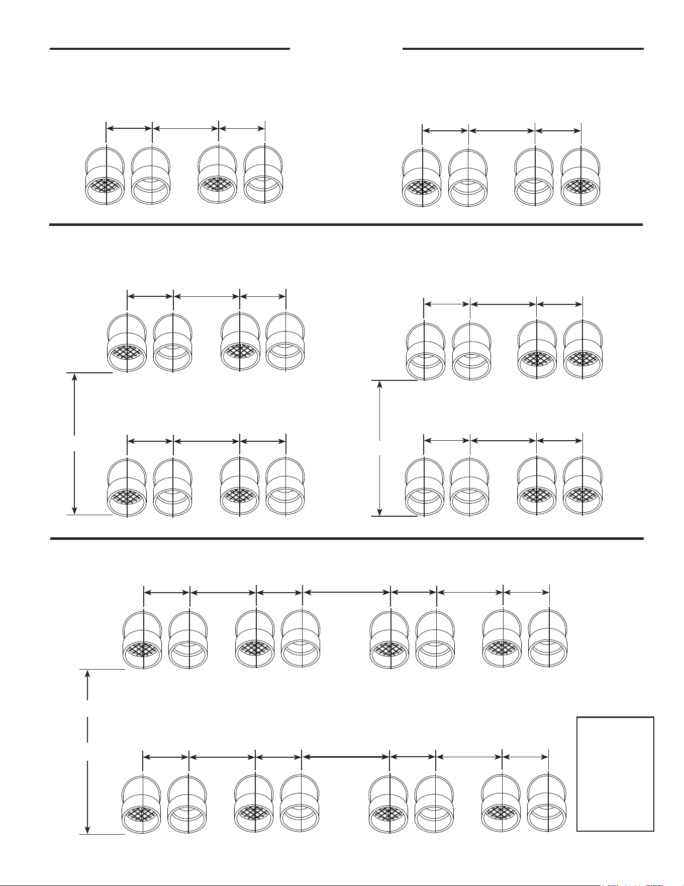
Figure 13a: Multiple Unit Venting
Example of 4 Units' Vent.
Intake
Exhaust
Intake Exhaust
24" to 36"
Heater #1
24" to 36"
Heater #2
24" Min.
Example of 2 Units' Vents.
Intake
Exhaust
Intake Exhaust
24" to 36"
Heater #1
24" to 36"
Heater #2
24" Min.
Intake
Exhaust
Intake Exhaust
24" to 36"
Heater #3
24" to 36"
Heater #4
24" Min.
16"
Figure 13c: Optional Configuration
Exhaust Exhaust
IntakeIntake
12" Min.
10" Min.
24" Min.
Exhaust Exhaust
IntakeIntake
12" Min.
10" Min.
24" Min.
16"
Figure 13b: Multiple Unit Venting Figure 13d: Optional Configuration
Example of 8 Units' Vent.
36" Min.
Intake
Exhaust
Intake Exhaust
24" to 36"
Heater #1
24" to 36"
Heater #2
24" Min.
Intake
Exhaust
Intake Exhaust
24" to 36"
Heater #3
24" to 36"
Heater #4
24" Min.
36" Min.
Intake Exhaust
24" to 36"
Heater #5
24" to 36"
Heater #6
24" Min.
Intake
Exhaust
Intake Exhaust
24" to 36"
Heater #7
24" to 36"
Heater #8
24" Min.
24"
Intake Exhaust
Figure 13e
Figure 13f
Example of 4 Units' Vent.
Intake Exhaust
IntakeExhaust
24" to 36"
Heater #1
24" to 36"
Heater #2
10" Min.
Horizontal Venting
inch to cm
10" = 25 cm
12" = 31 cm
16" = 41 cm
18" = 46 cm
24" = 61 cm
36" = 91cm
20
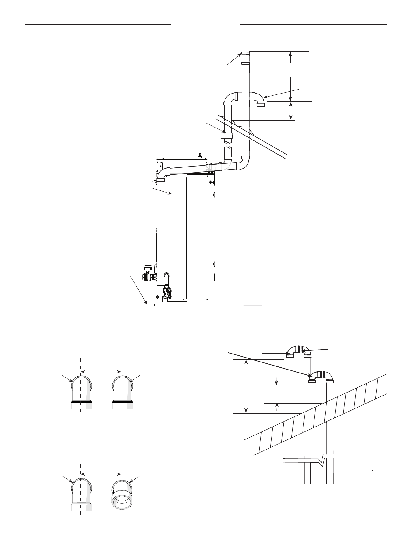
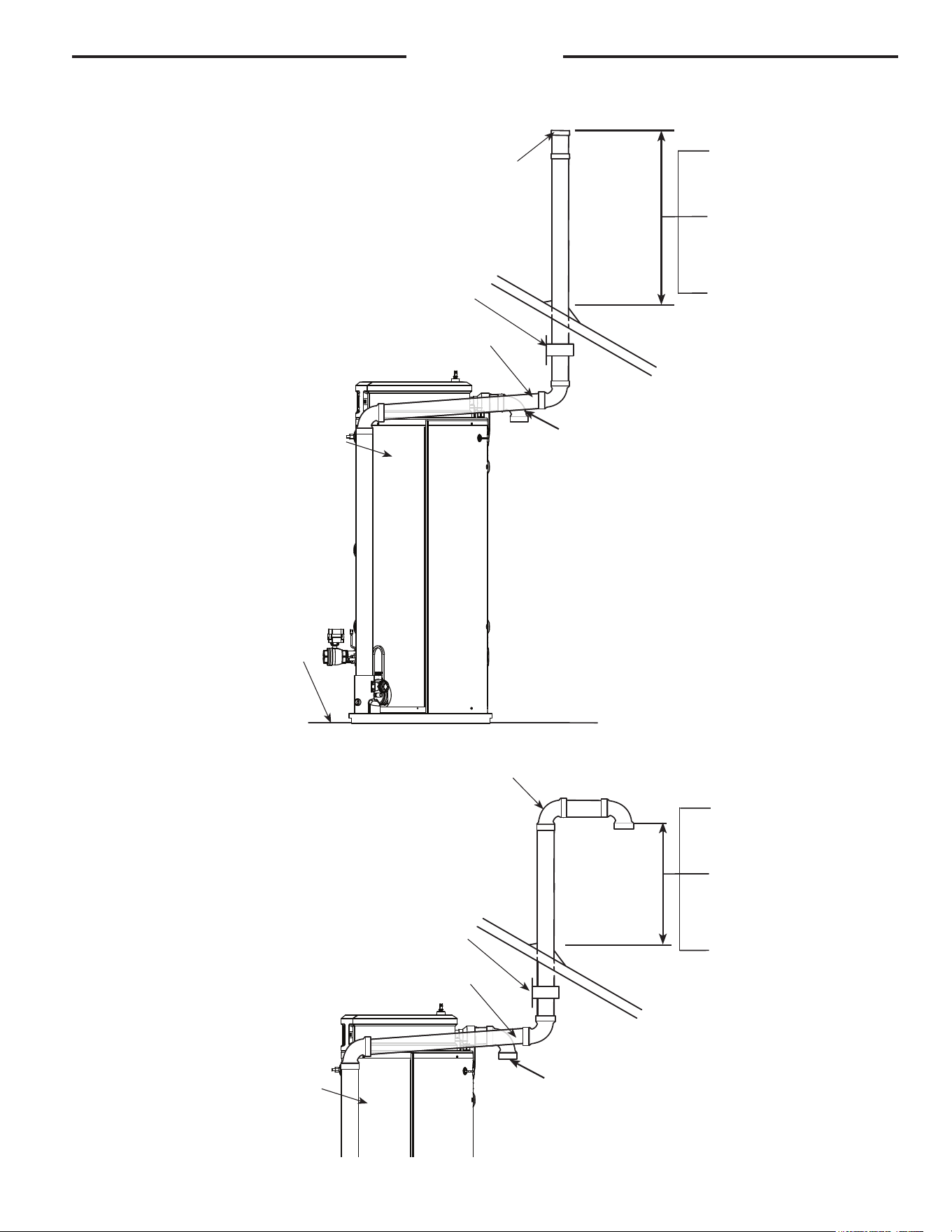
Figure 14. Typical Vertical Direct Vent System Installation
Installation
Combustion Air-Inlet
Terminal
Combustion Air-Inlet
Terminal
Exhaust Vent
Terminal
Exhaust Vent
Terminal
-B-
-A-
-B-
d
.008
d
.010
"D"
Min. 18 in. (46 cm) above Roof
Min. 12 in. (30.5 cm) above anticipated
snow level
Max. 24 in. (61 cm) above roof without
additional support)
Terminals with
1/2 in. (1.3
cm) Mesh
Protective
Screen
Elbow
Short Piece of Pipe
"D"
Combustion Air-Inlet
"D"
Alternate vertical venting with ex-
haust vent turned down - preferred
for cold climates.
Terminals spacing for horizontal or vertical venting.
Exhaust Vent
24" (61 CM) Min
(Support required).
90° Intake Terminal
Support Bracket
Water Heater
Floor
Straight Exhaust Terminal
"D"
NOTE:
For Model GHE119SU-500(A) If vent terminal are on the same
plane, use a 90° termincal on Exhaust Vent Terminal and 45°
terminal on Air-Inlet Terminal.
24 in. (61 cm) Min.
24 in. (61 cm) Min.
C
L
C
L
C
L
C
L
21
Installation
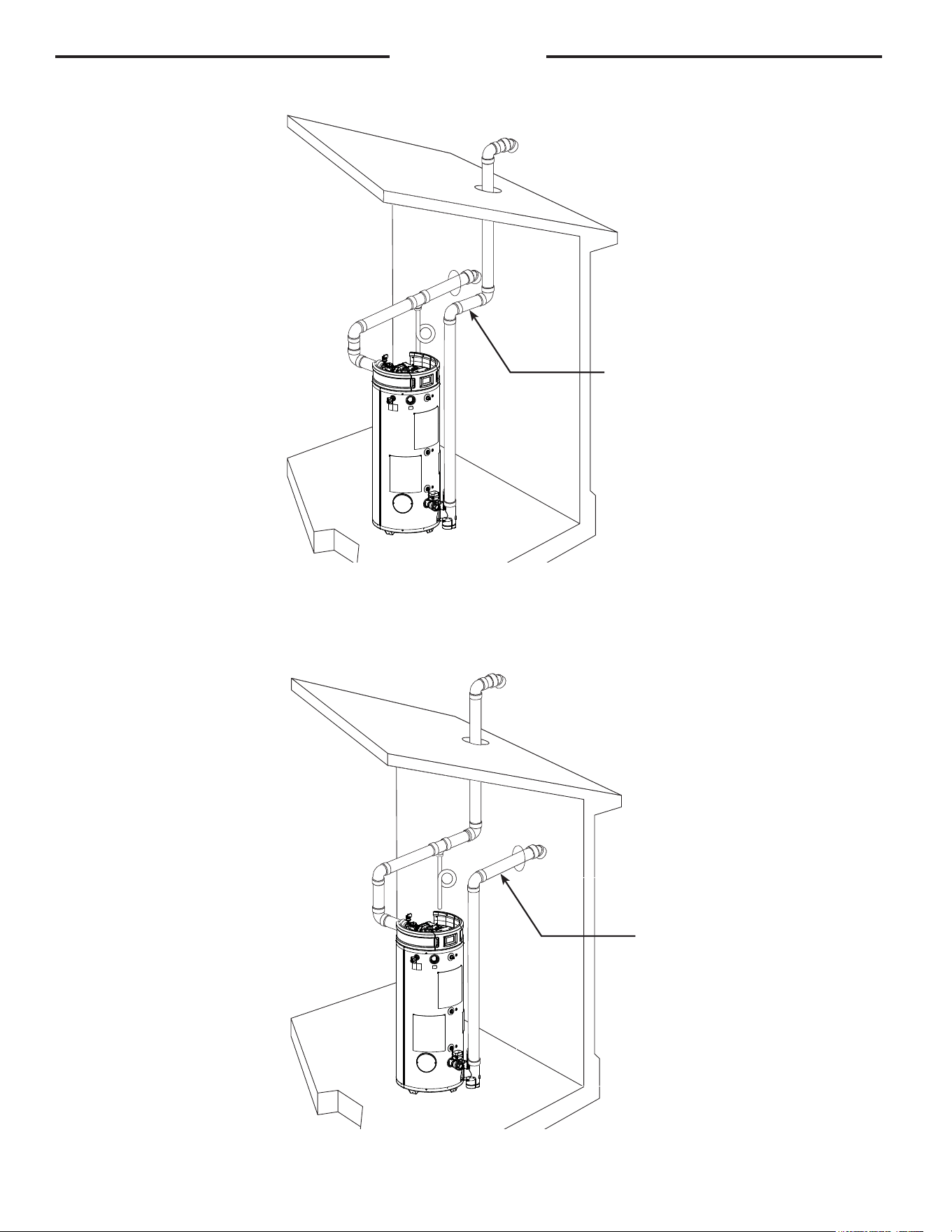
Figure 15. Typical Vertical Power Vent System Installation
Straight Exhaust Terminal
Support Bracket
Water Heater
Floor
90° Combustion Air
Inlet Terminal with
screen
Recommended support bracket be
placed on horizontal run
Min. of 18" (46 cm)
above roof.
Min. of 12" (30.5 cm)
above anticipated snow
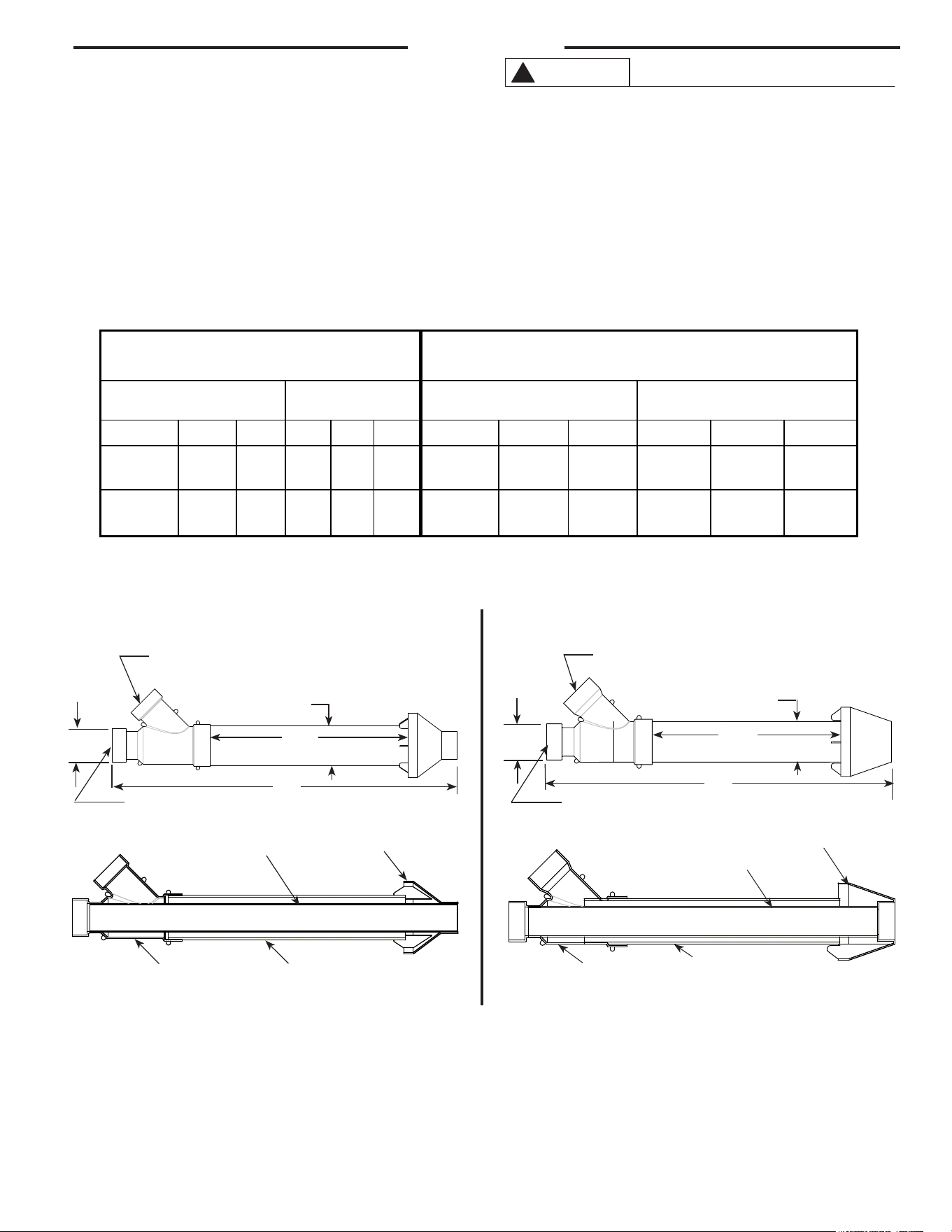
level.
Max. 24" (61 cm) above
roof without additional
support.
90° Combustion Air
Inlet Terminal with
Screen
Water Heater
Support Bracket
Exhaust Terminal
Alternate vertical venting with
exhaust vent turned down -
preferred for cold climates.
Recommended support bracket be
placed on horizontal run
Min. of 18" (46 cm)
above roof.
Min. of 12" (30.5 cm)
above anticipated snow
level.
Max. 24" (61 cm) above
roof without additional
support.
22
Installation
Figure 16. Direct Vent Vertical Vent Horizontal Intake
Direct Vent Horizontal Vent Vertical Intake
NOTE: Horizontal
venting shall be
installed with a slight
upward slope of 1/4"
per foot.
NOTE: Horizontal
venting shall be
installed with a slight
upward slope of 1/4"
per foot.
23
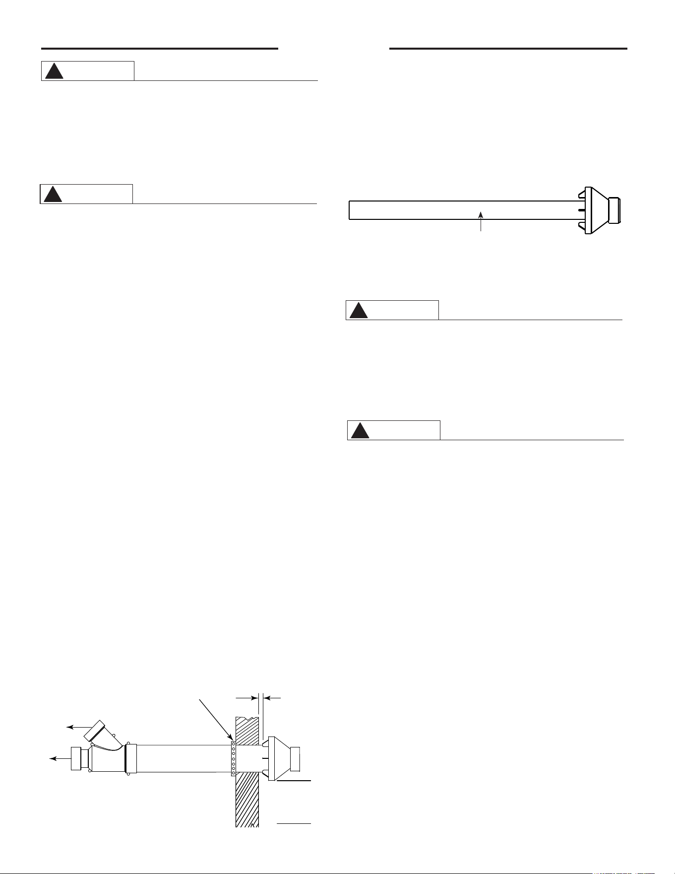
CONCENTRIC VENT TERMINAL INSTALLATION:
PROCEDURE
Improper installation, adjustment, service, or mainte-
nance can cause property damage, personal injury, or
death. Consult a qualified installer, service agency, or
gas supplier for information or assistance.
This kit must be used only for terminating this water
heater. DO NOT use this termination kit for any other
appliance. Using this kit on other appliances and/or
water heaters can result in property damage, personal
injury, or death.
NOTICE: Concentric vent kit requires that the joints be
cemented.
DO NOT operate this water heater with the rain cap
removed or recirculation of combustion products may
occur. Water may also collect inside larger
combustion-air pipe and flow to the burner assembly.
Failure to follow this warning could result in product
damage, improper operation, personal injury or death.
DO NOT use field-supplied couplings to extend pipes.
Airflow restriction will occur and the water heater
pressure switches may cause intermittent problems.
CAUTION
!
Installation
Installation:
1. Become familiar with concentric vent kit parts (see charts above).
2. Determine the best location for the termination kit.
3. Cut the recommended diameter hole for the nominal PVC pipe size called out in the charts above – Dim. “D”.
4. Partially assemble the vent kit by performing the following:
a. Cement concentric Y fitting to larger diameter pipe (see charts above).
b. Cement rain cap to smaller diameter pipe (see charts above).
PVC Intake/Combustion Air
"C"
"D"
"A"
PVC Vent/Exhaust
"C"
Kits for US
PVC Intake/Combustion Air
"C"
Kits for Canada
Concentric "Y"
Fitting
"D" Diameter
Pipe
"E" Diameter Pipe
Rain Cap
Kits for US Kits for Canada (ULC S636 Material)
Nominal PVC
Dimensions
Nominal PVC
Dimensions
“A” “B” “C” “D” “E” “A” “B” “C” “D” “E”
3” Vent Kit 39.98” 21” 3” 4” * 2” 3” Vent Kit 36.16”
(91.9 cm)
21”
(53.3 cm)
3”
(7.6 cm)
4” *
(10.2 cm)
2”
(5.1 cm)
4” Vent Kit 53.75” 34.8” 4” 6” ^ 4” 4” Vent Kit 55.96”
(142 cm)
38.25
(97.2 cm)
4”
(10.2 cm)
6” *
(15.2cm)
4”
(10.2 cm)
* Hole size for nominal 4” PVC would be 5" (12.7 cm) and for 6” PVC would be 7" (17.8 cm).
^ The pipe is on 6.3" OD, but a 7" hole can still be used.
"B"
"D"
"A"
"C"
"B"
PVC Vent/Exhaust
Rain Cap
"E" Diameter Pipe
Concentric "Y"
Fitting
"D" Diameter
Pipe
24
Installation
These instructions are intended as an aid to qualified
service personnel for proper installation, adjustment,
and operation of this kit. Read these instructions
thoroughly before attempting installation, adjustment,
or operation. Failure to follow these instructions can
result in improper installation, adjustment, service,
or maintenance possibly resulting in fire, electrical
shock, property damage, personal injury, or death.
This kit is to be used only for vent & combustion
air-inlet termination for power direct vent gas
water heaters. DO NOT use this kit to terminate
any other type of appliance. Failure to follow this
warning could result in fire, personal injury, or
death.
LOCATION: The Concentric Vent & Combustion Air-Inlet
Termination Kit can be installed in a horizontal or
vertical (roof) orientation. Before installation
procedures begin, determine the best location for
the termination kit.
IMPORTANT: When installing the kit, consider the
following when choosing a location:
• Kit is positioned where vent gases will not
damage nearby structure.
• Kit is positioned so that wind will not cause
combustion products, leaves, snow, or other
debris to enter the combustion air-inlet.
• Kit is positioned where it will not get damaged
by foreign objects (i.e.: balls, stones, etc.).
• Kit is positioned where vent gases will not be
inhaled or cause a nuisance.
NOTE: Ensure that the heights of the vent and/or
combustion air-inlet openings are at least 12"
above the anticipated snow level.
HORIZONTAL INSTALLATION
STEP 1:
Cut the proper size opening (see "D" in chart) in
the sidewall and install the field supplied weather-
seal boot/flashing for PVC pipe.
STEP 2:
From inside, insert the combustion air-inlet pipe
through the seal boot so that a maximum of 1”
clearance occurs between the outside wall and the
rain cap fins (See Figure 17). Ensure that no insula-
tion or debris accumulate in the pipe.
STEP 3:
Secure the combustion air-inlet pipe using a field
supplied perforated strap or a suitable type
material (see Figure 17).
STEP 4:
Assemble the vent pipe assembly by cleaning and
cementing the rain cap to the smaller diameter
vent pipe.
Note: If field disassembly is desired for cleaning, a
stainless steel screw may be used to secure the
rain cap to the PVC vent pipe.
When using the alternate screw method, pre-drill
a clearance hole in the rain cap slightly larger
than the screw and a pilot hole in the vent pipe to
prevent cracking of the PVC pipe. Cracking of the
PVC components will cause a failure of the
system, allowing combustion products to be
recirculated. Failure to follow this warning could
result in personal injury of death.
DO NOT operate the water heater with the rain cap
and elbow removed or recirculation of combustion
products may occur. The vent and combustion air-
inlet systems may also take in water, causing
damage to the water heater. Failure to follow this
warning could result in damage to the unit,
improper operation, personal injury, or death.
STEP 5:
From the outside, slide the vent pipe assembly
through the combustion air-inlet pipe and cement
the rain cap to the combustion air-inlet pipe. From
the inside, cement the "Y" fitting to the combustion
air-inlet pipe (see Figure 17 & 18).
STEP 6:
Complete the installation of the remainder of the
vent and combustion air-inlet systems as required
in this manual.
VERTICAL INSTALLATION
STEP 1:
Cut a proper size opening (see "D" in chart) in the
roof, and install field-supplied weather-seal boot/
flashing for the larger PVC pipe.
STEP 2:
From inside, insert the larger diameter combustion
air-inlet pipe up through the seal boot, ensuring that
no insulation or debris accumulate in the pipe. Ensure
termination height is above the 12” minimum
clearance anticipated snow level.
WA RNING
!
WA RNING
!
Figure 18
Vent Pipe Assembly
WA RNING
!
WA RNING
!
1" Maximum
Combustion
Air-Inlet to
Water Heater
Field Supplied
Strap
Exhaust
Vent from
Water
Heater
Min. of 12" (30.5
cm) above grade
or anticipated
snow level.
Figure 17
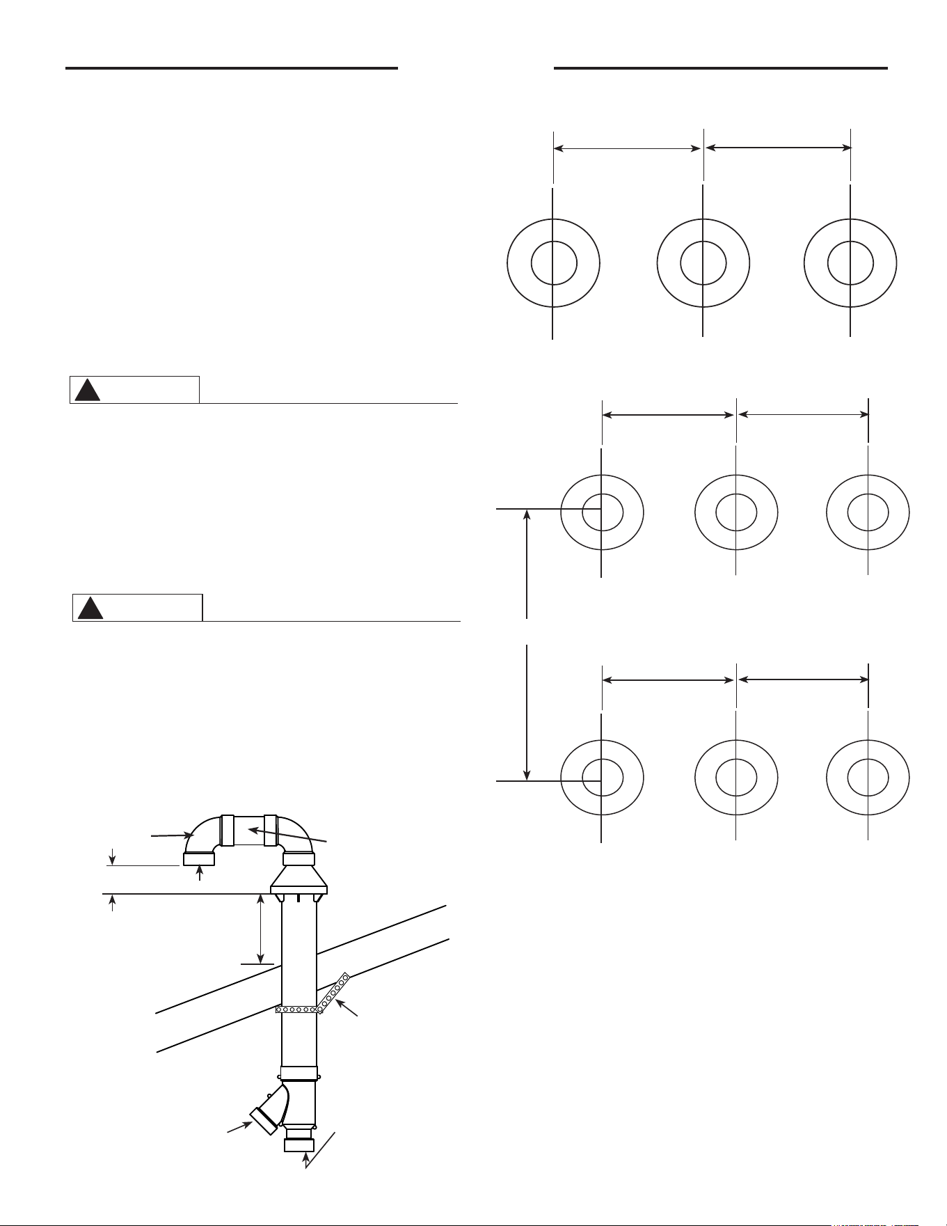
25
STEP 3:
Secure the combustion air-inlet pipe using a field
supplied perforated strap or a suitable type material.
(see Figure 19).
STEP 4:
Assemble the vent pipe assembly by cleaning and
cementing the rain cap to the smaller diameter
exhaust pipe as shown in Figure 18. Assemble the
90° elbow by cleaning and cementing it to the rain
cap. Assemble the field supplied PVC connector and
90° elbow by cleaning and cementing them together
as shown in Figure 19. The alternate screw method is
not necessary for the field supplied PVC parts.
Note: If field disassembly is desired for cleaning, a
stainless steel screw may be used to secure the
rain cap to the smaller diameter exhaust pipe.
When using the alternate screw method, pre-drill a
clearance hole in the rain cap slightly larger than
the screw and a pilot hole in the vent pipe to
prevent cracking of the PVC pipe. In a separate
location, pre-drill a slightly larger clearance hole
in the 90° elbow and a pilot hole in the rain cap for
the screw being used at that site. Cracking of the
PVC components will cause a failure of the system,
allowing combustion products to be recirculated.
Failure to follow this warning could result in
personal injury of death.
DO NOT operate the water heater with the rain cap
removed or recirculation of combustion products
may occur. The vent air pipes may also take in
water, causing damage to the water heater. Failure
to follow this warning could result in damage to the
unit, improper operation, personal injury, or death.
STEP 5:
From the roof top, slide the vent pipe assembly down
through the intake pipe and cement the rain cap to
the intake pipe. From the inside, cement the "y" fit-
ting to the intake pipe (See Figure 19).
STEP 6:
Complete the installation of the remainder of the
vent and air intake systems as required in this
manual.
Installation
WA RNING
!
WA RNING
!
Exhaust
Field Supplied
Strap
Combustion Air- to
Water Heater
Exhaust Vent From
Water Heater
Field Supplied
PVC Connector
Field Supplied
90° Elbow
Min. 18" (46 cm)
above roof or
anticipated snow level.
Figure 20 Multiple Sidewall or Vertical
Concentric Vents
36" (91 cm) Min.
36" (91 cm) Min.
Figure 20A Multiple Sidewall Concentric Vents
36" (91 cm) Min.
36" (91 cm) Min.
36" (91 cm) Min.
36" (91 cm) Min.
16" (40 cm)
Min.
Figure 19
Min. 12"
(30.5 cm)
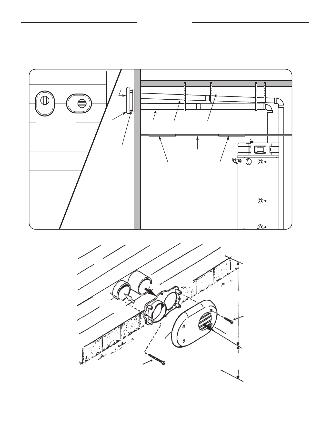
2626
Installation
Alternative Horizontal Vent Installations
For the GHE119-500 model alternative flat horizontal vent termination kit (SP21069) is available for 4" pip-
ing. Please refer to the instruction sheet packaged with the kit for complete installation instructions.
Flat Horizontal
Termination Kit
(this termination
can be rotated)
Exhaust
Vent
Flat
Termination
Kit
Air Intake
Vent
Air Intake
Pipe
Exhaust
Vent Pipe
Upward Slope
to Termination
Inspection Access
Panel (Optional)
Inspection Access
Panel (Optional)
Ceiling
12" Minimum to
overhang
Maintain 12" minimum clearance
above highest anticipated snow
level or grade whichever is greater
1" Screws
(4 req.)
2" Screws
(4 req.)
Vent
Vent
Cap
Vent
Plate
Vent
Combustion
Air
27
Installation
The GHE80SS/SU, GHE100SS/SU, and GHE119SS/SU models have been certified to use polypropylene pipe for both the
intake and exhaust vent systems, but must use the current PVC vent terminations (including concentric vents). All poly-
propylene pipe and fittings listed in the tables below are ULC-S636 listed.
*Can also be BC instead of C. A lock ring should be used at every pipe/fitting connection.
**Connector rings should be used for all pipe/fitting connections.
PP Chart 1
PP Chart 2
Centrotherm
M&G
Duravent
Nominal
Pipe
Diameter
PVC to PP
Adapter
Connector
Ring**
45 Degree
Elbow
87 Degree
Elbow
Vent
Material
Terminals
2"
3"
4"
6"
ISAGL0202
ISAGL0303
ISAGL0404
ISAGL0606
IANS02**
IANS03**
IANS04**
IANS06**
ISELS0245
ISELS0345
ISELS0445
ISEL0645
ISELL0287
ISELL0387
ISELL0487
ISEL0687
ISVL02-1,2,3,6
ISVL03-1,2,3,6
ISVL04-1,2,3,6
ISVL06-1,2,3,6
USE CURRENT
PVC
TERMINALS
Nominal
Pipe
Diameter
PVC to PP
Adapter
Locking
Band
45 Degree
Elbow
90 Degree
Elbow
Vent
Material
Terminals
2"
3"
4"
6"
2PPS-ADL
3PPS-ADL
4PPS-ADL
PPS-PACL
2PPS-LBC
3PPS-LBC
4PPS-LBC
6PPS-LBC
2PPS-E45C*
3PPS-E45C*
4PPS-E45C*
6PPS-E45C*
2PPS-E90C*
3PPS-E90C*
4PPS-E90C*
6PPS-E90C*
2PPS-12C,36C,72C*
3PPS-12C,36C,72C*
4PPS-12C,36C,72C*
6PPS-12C,36C,72C*
USE CURRENT
PVC
TERMINALS
The GHE80SS/SU, GHE100SS/SU, and GHE119SS/SU models can be vented using rigid polypropylene pipe, to the
same vent lengths called out in the current GHE manuals (AP14729-5 and AP18494). The overall vent length (pipe and
elbows) must fall within the allowable vent terminal configurations shown in the manuals. An adapter (see charts above)
will be needed to join the polypropylene pipe to the PVC pipe shipped with the units.
At the vent terminations, the polypropylene pipe will need to convert back to one of the allowable PVC termination
configurations currently used.
Page 28 shows what a complete vent set up would consist of for either the intake or exhaust vent system.
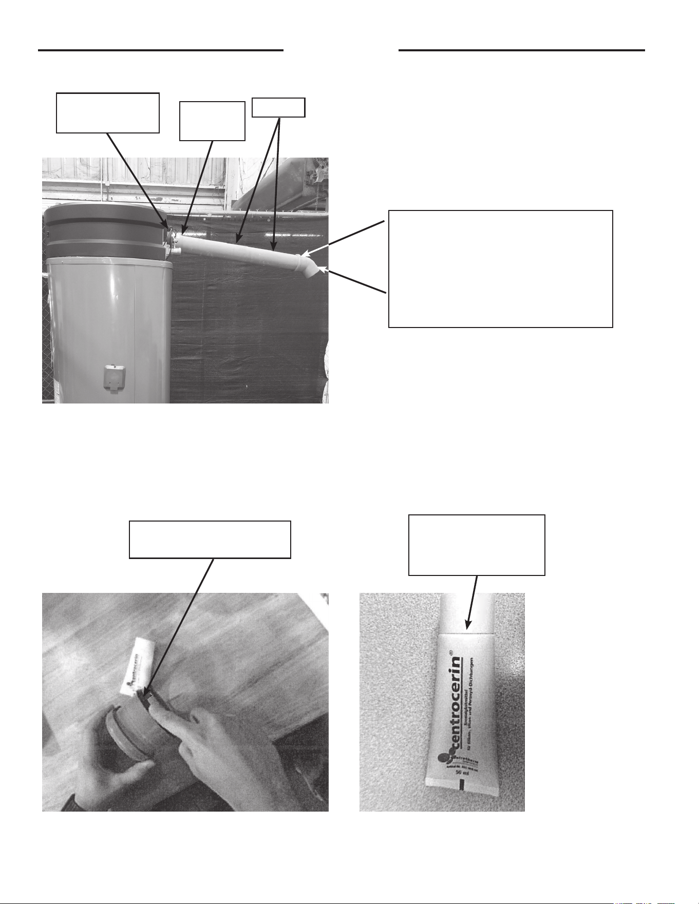
28
The first step to install the PP pipe is to find a PVC to PP adapter and lubricate the gasket that will slide into the PVC
fitting. The lubricant for the Centrotherm parts is called Centrocerin. Apply a small amount onto your finger and then
apply to the outer gasket.
Straight piece of PP pipe connected to a
PP to PVC adapter vent terminal installed
onto a PP to PVC adapter.
Note: The hole through the wall should
be sized for the PP pipe, which has a
smaller OD than PVC pipe.
PP pipe
PVC to PP
adapter
Make sure to lubricate all
gaskets, external and internal.
Centrocerin
lubricant for Centrotherm
PP pipe and fittings
PVC pipe shipped
with the unit
Installation
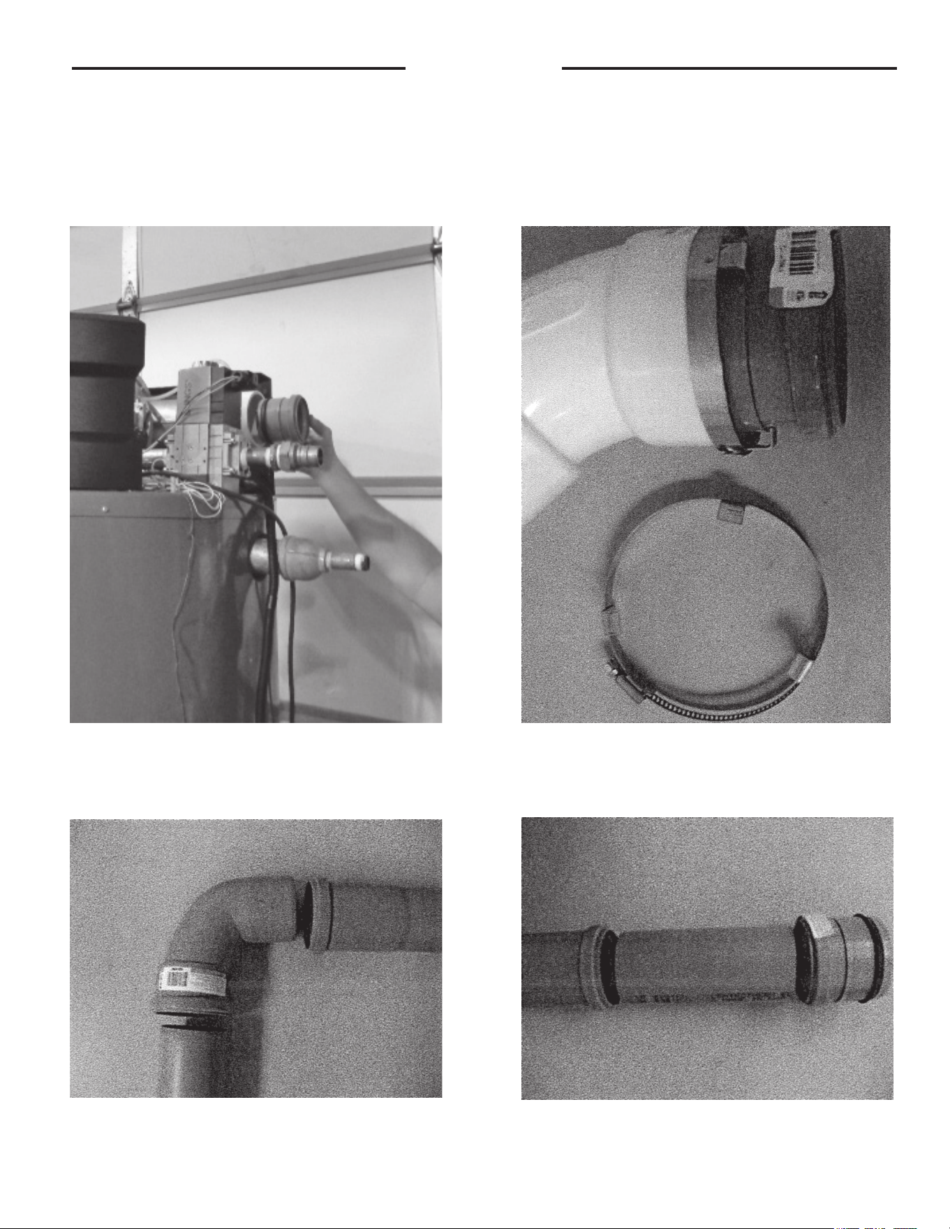
29
The PVC to PP adapter should then be installed into the PVC couplings on the inlet air and exhaust vent installed on the
unit. The sealing gasket will require some type of lubricant to make it easier to install the adapter.
Both Centrotherm and M&G Duravent recommend a connector ring to be installed between the PVC part and the PP
part. The connector ring for the Centrotherm pipe (either IAFC02, IAFC03, or IAFC04) is shown below. The connector ring
for the M&G Duravent pipe is shipped with the PVC to PP adapter..
Pipe and fittings are then installed to reach the area for the vent terminations. Each bell end of the pipe has a gasket,
which should be lubricated before the next piece of pipe or fitting is installed.
Installation
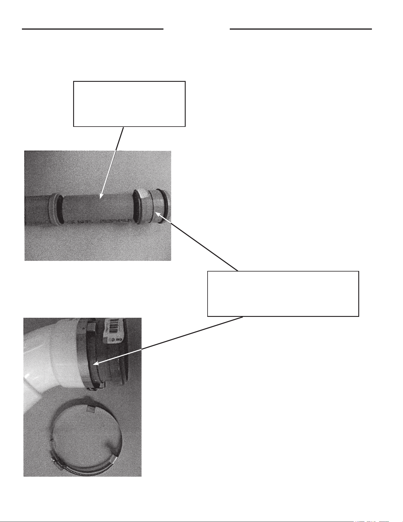
30
To be able to use a PVC termination, a short piece of PP pipe will need to be cut, as shown below, to transition from the
bell end of the pipe to the PP to PVC adapter.
Cut a piece of PP pipe that is long
enough to go through the wall and
have about 2" protruding on each
side of the wall.
The PP to PVC adapter can either be installed on
the pipe or into the vent terminal for the next step.
The final step is to make sure the vent terminal is
attached and secured to the adapter.
Installation
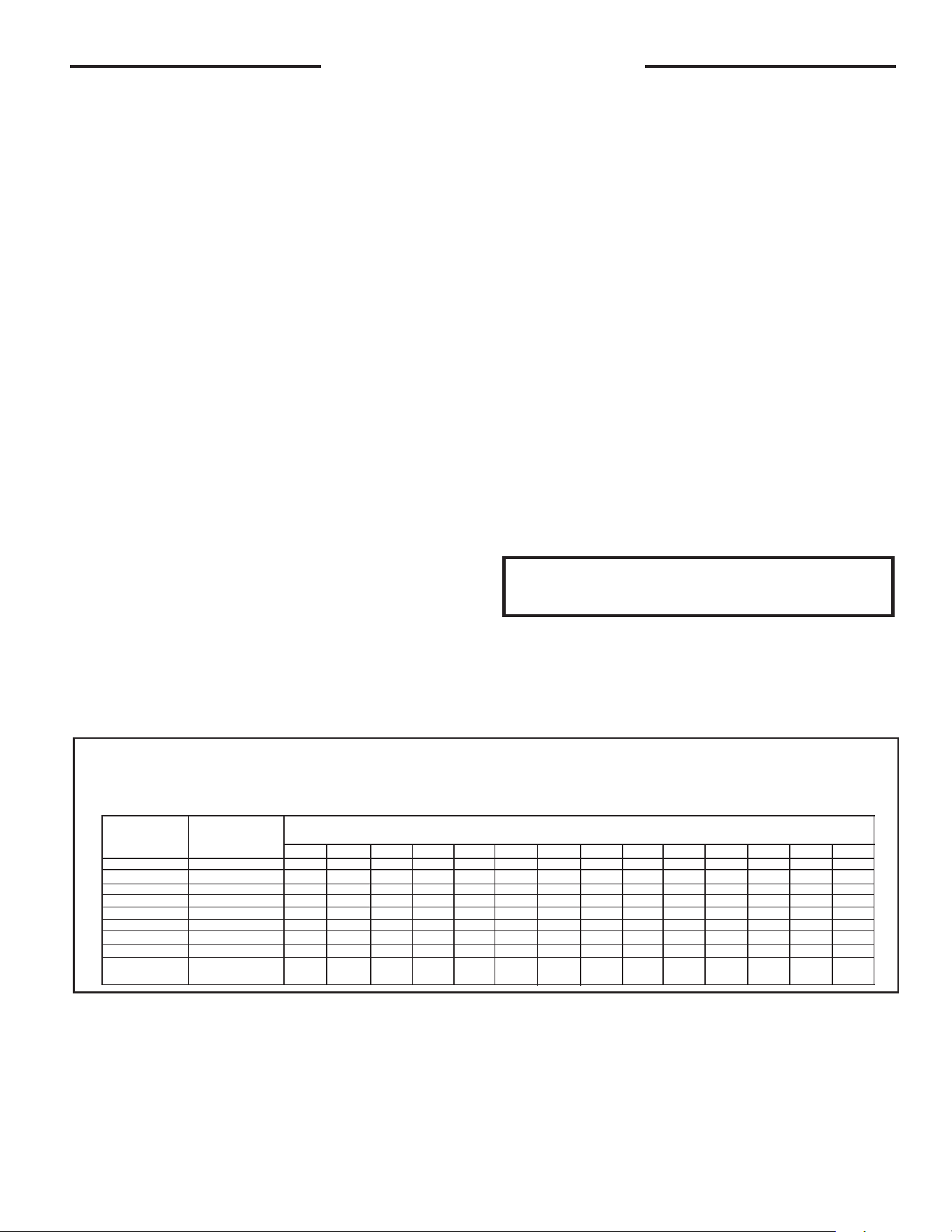
31
A. Water Heater Location
❑ Close to area of vent.
❑ Indoors and protected from freezing temperatures.
❑ Proper clearance from combustible surfaces
observed and water heater is not installed on a
carpeted floor.
❑ Air supply free of corrosive elements and flammable
vapors.
❑ Provisions made to protect area from water
damage.
❑ Sufficient room to service the heater.
B. Water Supply
❑ Water heater completely filled with water.
❑ Water heater and piping air vented.
❑ Water connections tight and free of leaks.
C. Gas Supply
❑ Gas line equipped with shut-off valve, union, and
sediment trap/drip leg.
❑ Approved pipe joint compound used.
❑ Minimum pipe size of 3/4"; NO flex pipe.
❑ Recommended a minimum of 10" WC inlet
pressure for natural gas.
❑ Soap and water solution used to check all
connections and fittings for possible gas leak.
❑ Gas company inspected installation (if required).
❑ Measure the combustion (CO2%) level.
D. Relief Valve
❑ Discharge line run to open drain.
❑ Discharge line protected from freezing.
E. Venting
❑ All pipe connections are secure (at blower, vent
terminals and for each pipe joint connection), and
all pipes properly supported.
❑ Vent terminals mounted properly in allowed
locations, with proper clearances .
F. Condensate
❑ Condensate trap installed and primed.
❑ Condensate neutralizer installed (if required).
G. Wiring
❑ Correct power supply (120 VAC).
❑ Electrical connections are tight.
❑ Water heater is properly grounded with proper
polarity.
Installation Check List
TABLE 2
For U.S. Installations
Maximum Capacity of Pipe in Cubic Feet of Gas per Hour for Gas Pressures of
0.5 psig or Less and a Pressure Drop of 0.3 Inch Water Column
Based on a 0.60 Specific Gravity Natural Gas; If 1.5 Specific Gravity L.P. Gas is used, multiply capacity by 0.63
Nominal Internal
Iron Pipe Size, Diameter
Inches Inches 10 20 30 40 50 60 70 80 90 100 125 150 175 200
3/4 .824 278 190 152 130 115 105 96 90 84 79 72 64 59 55
1 1.049 520 350 285 245 215 195 180 170 160 150 130 120 110 100
1 1/4 1.380 1,050 730 590 500 440 400 370 350 320 305 275 250 225 210
1 1/2 1.610 1,600 1,100 890 760 670 610 560 530 490 460 410 380 350 320
2 2.067 3,050 2,100 1,650 1,450 1,270 1,150 1,050 990 930 870 780 710 650 610
2 1/2 2.469 4,800 3,300 2,700 2,300 2,000 1,850 1,700 1,600 1,500 1,400 1,250 1,130 1,050 980
3 3.068 8,500 5,900 4,700 4,100 3,600 3,250 3,000 2,800 2,600 2,500 2,200 2,000 1,850 1,700
4 4.026 17,500 12,000 9,700 8,300 7,400 6,800 6,200 5,800 5,400 5,100 4,500 4,100 3,800 3,500
Length of Pipe, Feet
For maximum pipe capacity for installations in Canada, refer to CAN/CSA B149.1. For natural gas, refer to Tables
A.1 through A.17. For propane (LP) gas, refer to Tables B.1 through B.12.
NOTE: Each water heater should have its own
regulator located a minimum of 8' from unit.
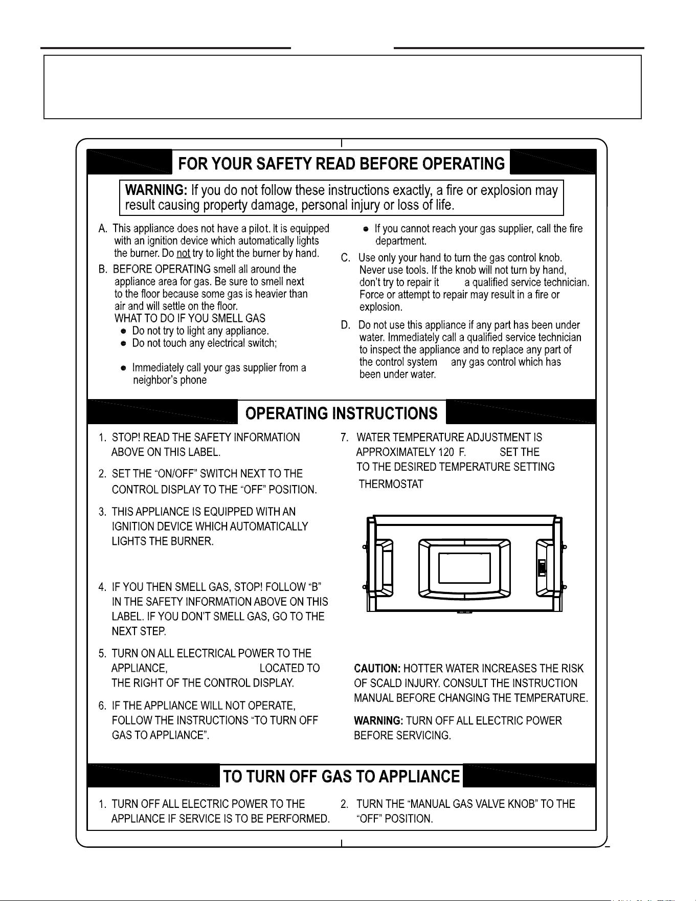
32
Operation
Before operating this water heater, be sure to read and follow the instructions on the label pictured below and all other labels and warnings on
the water heater and printed in this manual. Failure to do so can result in unsafe operation of the water heater resulting in property damage,
bodily injury, or death. Should you have any problems reading or understanding the instructions in this manual, STOP, and get help from a
qualified person.
Do not use
, and follow the gas supplier’s
WITH THE SWITCH
°
instructions.
any phone in your building.
. Call
or
(49°C.)
33
Operation
A. DO turn off manual gas shut-off valve if water heater has been
subjected to over heating, fire, flood, physical damage or if gas
supply fails to shut off.
B. DO NOT turn on water heater unless it is filled with water.
C. DO NOT turn on water heater if cold water supply shut-off
valve is closed.
D. DO NOT store or use gasoline or other flammable vapors
and liquids, such as adhesives or paint thinner, in vicinity of
this or any other appliance. If such flammables must be used,
open doors and windows for ventilation, and all gas burning
appliances in vicinity should be shut off, including their pilot
lights, to avoid vapors igniting.
NOTICE: Flammable vapors may be drawn by
air currents from surrounding areas to the water
heater.
E. DO NOT allow combustible materials such as newspaper,
rags or mops to accumulate near water heater.
F. If there is any difficulty in understanding or following
the OPERATION or MAINTENANCE instructions, it is
recommended that a qualified person or serviceman perform
the work.
Hydrogen gas can be produced in a hot water system
served by this water heater that has not been used for
a long period of time (generally two weeks or more).
HYDROGEN GAS IS EXTREMELY FLAMMABLE!! To
dissipate such gas and to reduce risk of injury, it is
recommended that the hot water faucet be opened for
several minutes at the kitchen sink before using any
electrical appliance connected to the hot water system.
If hydrogen is present, there will probably be an unusual
sound such as air escaping through the pipe as the
water begins to flow. DO NOT smoke or use an open
flame near the faucet at the time it is open.
SAFETY PRECAUTIONS
CAUTION
!
1. TEMPERATURE SETTINGS — The temperature is
adjusted to 120° F when shipped from the factory. To
meet commercial water use needs, it is adjustable up
to 185°F (85°C). However, water temperatures over
125°F (52°C) can cause severe burns instantly or
death from scalds. This is the preferred starting point
for setting the control for supplying general purpose
hot water.
Safety and energy conservation are factors to be
considered when setting the water temperature. The
most energy efficient operation will result when the
temperature setting is the lowest that satisfies the
needs consistent with the application.
Hotter water increases the potential for hot water SCALDS.
When this water heater is supplying general purpose hot
water requirements for individuals, a thermostatically
controlled mixing valve for reducing point of use water
temperature is recommended. Contact a licensed plumb-
er or the local plumbing authority for further information.
Outlet water temperature will vary during normal operat-
ing cycles. Reliable temperature readings should be taken
shortly after main burner cycles off during a period of little
or no use.
2. EMERGENCY SHUTDOWN —
Should overheating occur or the gas supply fail to shut
off, turn off the manual gas control valve to the appliance.
DO NOT use this appliance if any part has been under water.
Immediately call a qualified service technician to inspect the appliance
and to replace any part of the control system or any gas control which has
been under water.
If the water heater has been subjected to fire or physical damage, turn
off gas at the manual gas control (shut-off) valve. DO NOT operate
the water heater again until it has been checked out by a qualified
service technician.
DANGER
!
WA RNING
!
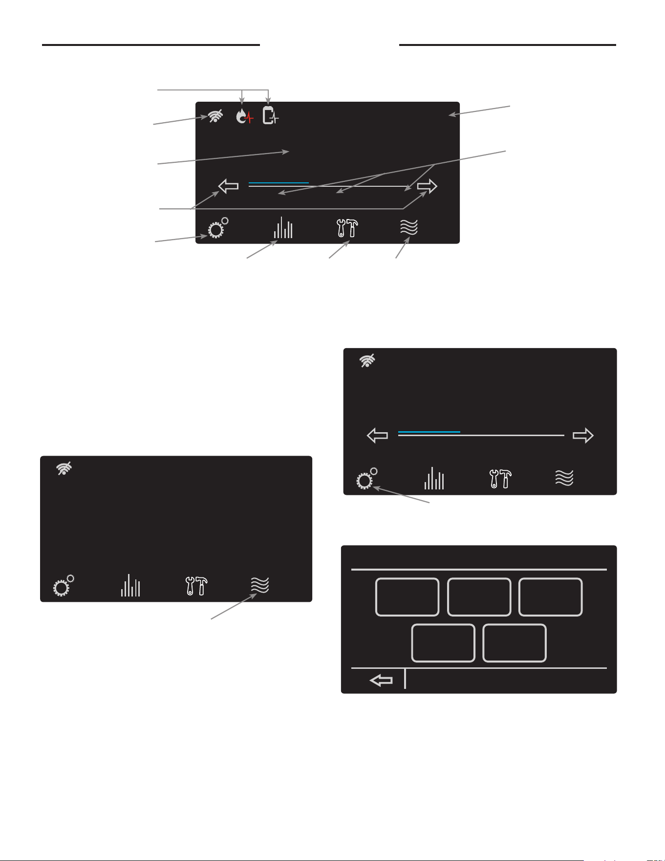
34
User Interface
NAVIGATING THE HOME SCREEN:
Status: Standby
StatusSettings
warm hot very hot
Disable
120°
Service
Operating Status
Setting Menu
Button
Status Button Service
Menu Button
Enable/Disable
Button
Rapid Temperature
Adjustment
Wifi Indicator
and Settings
Health Indicator
Icons
Temperature
Setting
Temperature
Adjustment
Startup
Once power is applied to the water heater and the On
button is pressed, the Startup Wizard on the LCD will
go over the below features:
1. Setting of Time and Date
2. Setting Hours of Operation for the business
3. Wifi Setup
Follow the on-screen instructions to complete setup.
Some of these items can be skipped if a later setup is
desired.
Enabling (turning on) the Unit
Temperature Adjustment
Tank temperature will be maintained according to the
setting on the home screen. If the water temperature
setting needs adjustment, use the arrows on the display
to select desired temperature.
The display also has a rapid temperature adjustment
feature that corresponds to the below temperature set-
tings.
Warm: 110°F
Hot: 140°F
Very hot: 180°F
Touching the text ‘warm’, ‘hot’, or ‘very hot’ will adjust
the temperature to the above temperature setting.
Setting Menu
The settings function on the water heater display allows
access to the basic settings, configurations, schedules,
bacnet, and the time/date.
Status: Standby
Water Heater Disabled
StatusSettings Enable
Service
Press the enable button to
turn the water heater on
Pressing the settings button will
allow access to water heater settings
Status: Standby
StatusSettings
warm hot very hot
Disable
120°
Service
settings
wifi setup
bacnet time/date
basic configs schedule
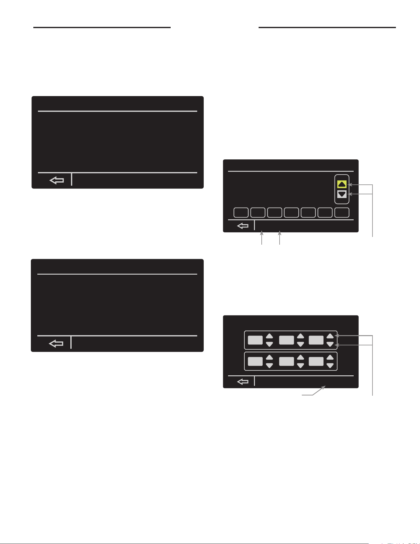
35
User Interface
BASIC SETTINGS: The basic settings in you water heater
can allow you to change the temperature unit, screen
adjustment lock/unlock, enabling/disabling the alarm
beep, and your EcoNet network instance. Simply select
the setting by tapping it, and press the Up/Down arrows
to make adjustments. WiFi setup can be accessed from
this screen as well.
CONFIGURATION SETTINGS: The configuration settings
on your water heater allows you to control the differential
temperature set point, turning on/off the recirculation
pump, auxiliary input/output, enabling/disabling
modulation, and how your hot water heater reacts to a
detected leak.
The setting can be highlighted by tapping and then ad-
justed with the up/down arrows.
The Differential can be adjusted from 1°F to 30°F. The
recommended differential is 12°F.
This water heater has a modulation algorithm that can
be disabled by tapping ‘No’ in front of Modulation Dis-
abled and making adjustments by tapping the up/down
buttons.
Water heater behavior in response to leak can be
changed from Alarm Only to Disable When Leak De-
tected.
Shutoff Valve (on premium models only) behavior re-
sponse can be selected to the following:
• Open
• Closed
• Close if Leak Detected: Always close the valve when
leak is detected.
• Close if Unocc. Leak Detected (based on unoccupied
times from the schedule function). Water heater will
alarm only during the operating hours.
SCHEDULE SETTINGS: The schedule settings allows you
to control when your hot water heater will be enabled/
disabled. Your heater allows you to select a day you
want and set the times when the heater will be in use.
You can also copy/paste the day you select and apply
it to other days as well.
TIME/DATE SETTINGS: By selecting time/date you can
change the water heaters current set time. You can also
select the daylight savings time function to automati-
cally adjust the time for daylight savings.
BacNet
This water heater is compatible with BacNet MS/TP
protocol. Please refer to the GHE BacNet instruction
sheet for details on the setup.
basic settings
Temperature Display
Screen Adjustment Lock?
Beep On Alarm
EcoNet Network Instance
Elevation
Fahrenheit
No
Enabled
1
Normal
config. settings
Differential Temp Setpt.
Recirc. Pump Config
Aux Input Select
Aux Output Select
Modulation Disabled?
When Leak Detected
12.0° F
Off
Flow Sensor
None
No
Alarm Only
schedule settings
Wed. Jan.11, 2:49 pm
Morning:
Night:
Mon.
08:00 am
06:00 pm
Time
Occupied
Occupied
Schedule
Tue.
copy
day
paste
day
cancel
Wed. Thu. Fri. Sat. Sun.
set to time and date
accept
D.S.T.
enabled
:
10 54 am
:
Jan. 11 2017
The up/down arrows enable
you to adjust the time of the
morning/night run times.
By selecting a day and then access-
ing the copy function, you can
paste that day’s settings onto other
The up/down arrows allow
you to control the time,
month, day, and year.
The D.S.T function allows you to
adjust the time for daylight sav-
ings time.
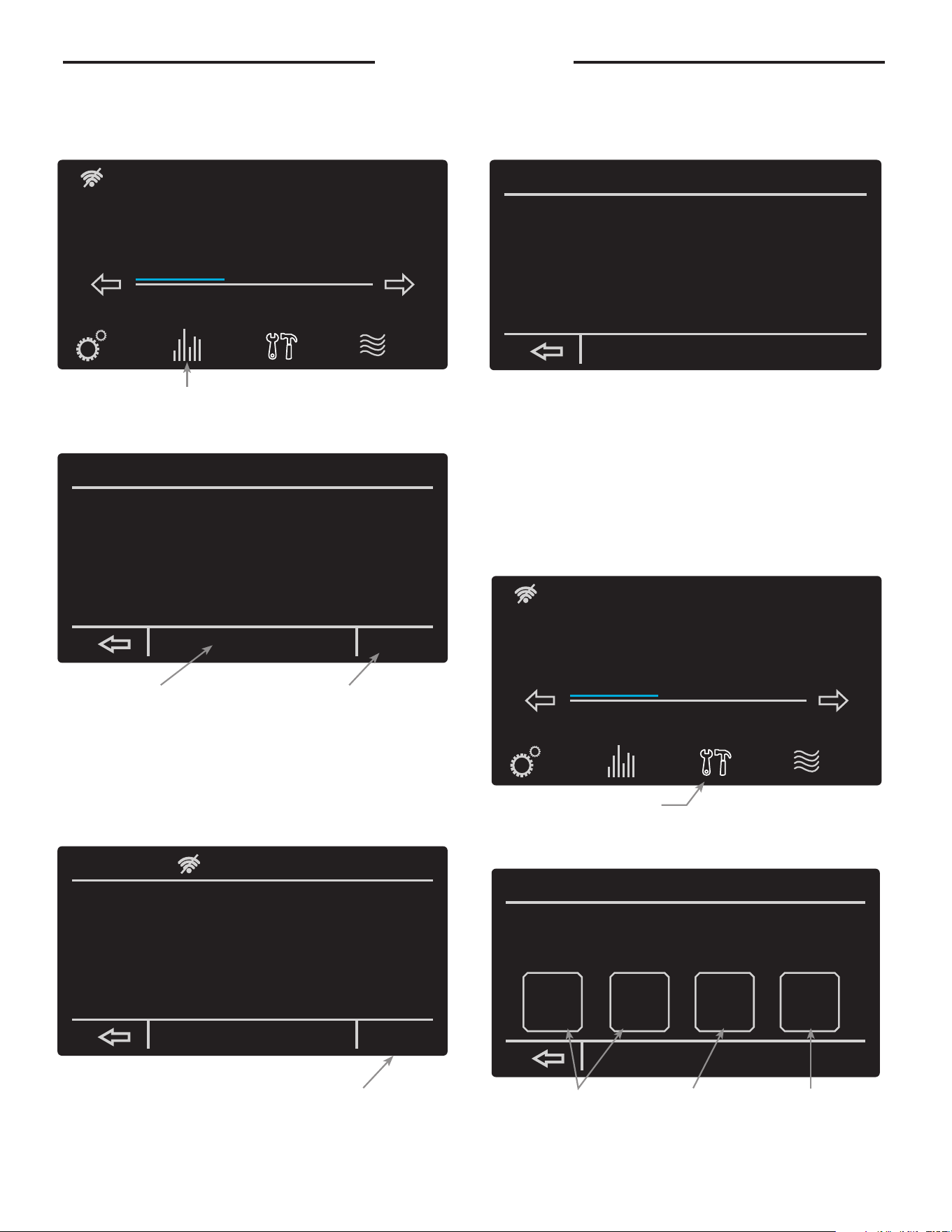
36
Status Menu
The Status screen provides information on the current
operating status, diagnostics and sensors. This screen
also provides information on the WiFi status.
WI-FI STATUS: After selecting the Wi-Fi status function,
you will be brought to a prompt showing you the cur-
rent state of your water heater’s Wi-Fi and the ability
to set-up your water heater’s Wi-Fi.
MORE FUNCTION: Selecting the more function your heat-
er will bring you to a prompt showing you the current
temperatures of the lower/upper tank, Flue tempera-
ture, ECO switch state, and Auxiliary relay state.
Service Menu
The service screen provides information on the product
description, alarms, system health, and service alerts.
Alarm details can be found in the "Before You Call Ser-
vice" section of the manual.
In case there is an active alarm, the "Service" button
will blink on the home screen. Pressing the "Service"
button will show a new screen containing the active
alarms and alarm history.
User Interface
By pressing the Status button, you will
be taken to a prompt showing the state
of your water heater’s many features.
By selecting the service function,
you will be taken to a prompt
giving you access to the heater’s
alarms, health, and alerts.
By selecting Wi-Fi status, you can
access the status of your water
heater’s Wi-Fi and even set it up.
By selecting more, you can access
the temperatures of your water
heater, ECO switch state, and
auxiliary switch state.
Selecting the Wi-Fi setup function
will bring you to a prompt allow-
ing you to connect your water
heater to your home Wi-Fi.
Current Alarms and Alarm
History allows you to
access any current alarms
that have been tripped and
view a list of previous
alarms.
System Health
will show you the
status of the tank’s
combustion health
and overall tank
health.
Service Alerts will allow
you to set how often you
want to be alerted to check
venting, clean the drain
trap, replace the neutralizer,
and to drain and inspect
the tank.
Status: Standby
StatusSettings
warm hot very hot
Disable
120°
Service
Status: Standby
StatusSettings
warm hot very hot
Disable
120°
Service
Status: Standby
Gas Line Press. Switch
Gas Valve State
Fan Prove Press. Switch
Air Intake Press. Switch
Exhaust Press. Switch
Current Fan Speed
Flame Current
Open
Closed
Open
Closed
Closed
0 RPM
0.0 uA
morewifi status
wifi status
WiFi Device Status............
WiFi Signal Strength [dBm]....
Econer wifi SW Version........
WiFi Module SW Version........
MAC Address...................
SSID..........................
IP Address ...................
Subnet Mask...................
Gateway.......................
Ready To Connect
0
RH-WIFI-02-01-05
14.76.36.P103
F0-03-8C-B3-C6-CC
wifi setup
Status: Standby
Upper Tank Temp
Lower Tank Temp
Flue Temperature
ECO Switch State
Auxiliary Relay State
159.8°
68.6°
92.7°
Closed
None
service
Product Model Number:
Product Serial Number:
Software Version Number: WH-GHE1-00-00-86
current
alarms
alarm
history
system
health
service
alerts
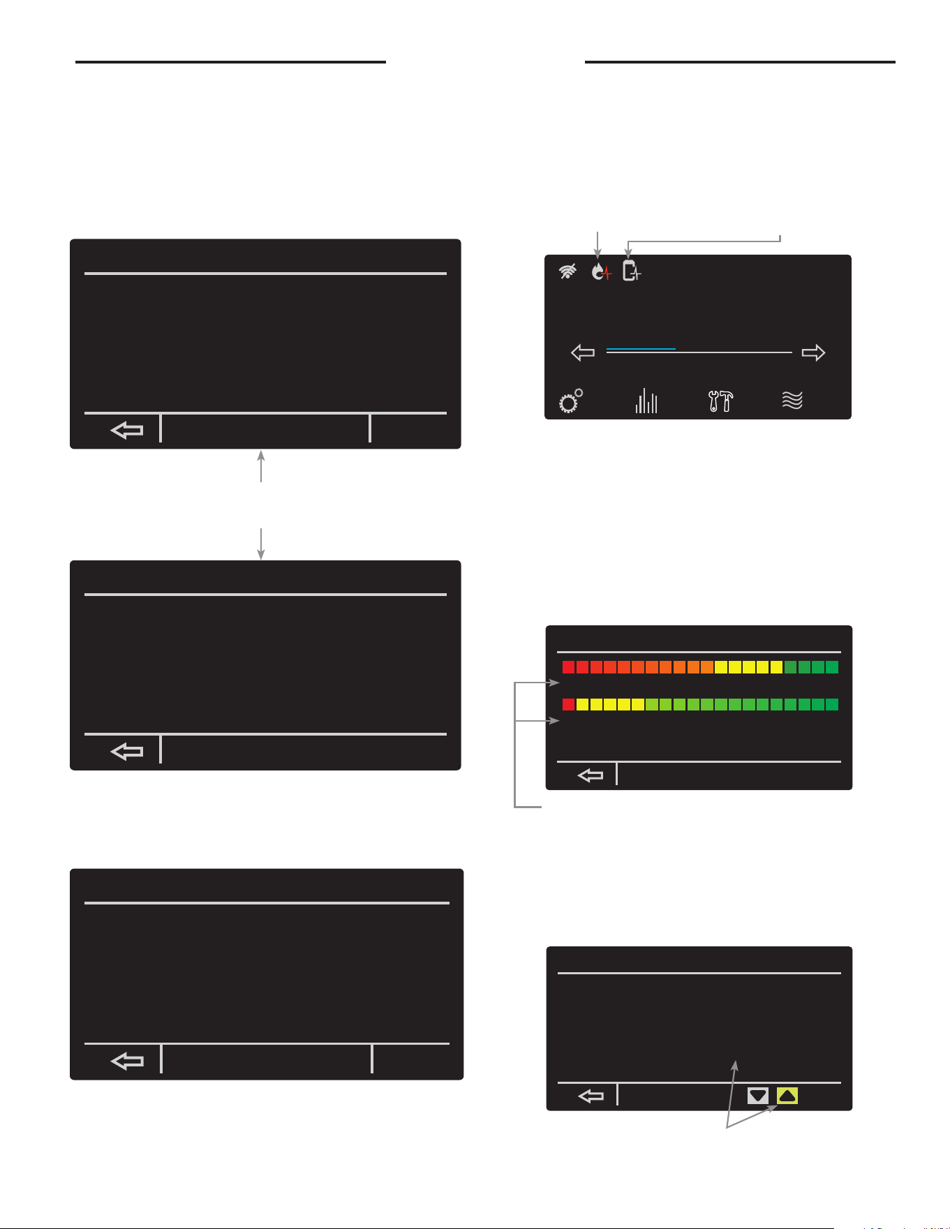
37
User Interface
ALARMS: The current alarms function allows you to see
any problems that have been detected by your water
heater. Also, by selecting on the current alarm you can
press “more info” to read more on the current problem
of your water heater. Alarm history allows you to see
any of the previous alarms that have gone off in the
past and give you the ability to clear those previous
alarms.
ALARM HISTORY: The alarm history function allows you
to see the previous alarms that have been detected by
your water heater in the past.
SYSTEM HEALTH: The system health function allows you
to see the current health of your hot water heater’s
combustion health and tank health status. The com-
bustion health and tank health each have three levels
of health:
SERVICE ALERTS: By selecting the Service alerts func-
tion you will be able to adjust how often you want to be
alerted to drain and inspect the tank, clean the drain
trap, check the venting, and to replace the neutralizer.
current alarms
A007 Exhaust Switch open. Check Wiring/Venting
more
info
clear
service alerts
Drain & Inspect Tank:
Check Venting:
Clean Drain Trap:
Replace Neutralizer:
Enabled
Enabled
Enabled
Enabled
9 months
6 months
1500 hours
1500 hours
9.0 left
6.0 left
1500 left
1500 left
By selecting “more info” you can
be given a more in-depth explana-
tion of the current alarm.
The health of your system’s combustion system and overall health
can be seen here. This screen be accessed by tapping the health indi-
cator icons on the home screen.
This symbol will appear on your home
screen if your combustion health is
critical. Pressing this icon will take the
user to the Health Status Screen
This symbol will appear if your
tank health status has reached criti-
cal. Pressing this icon will take the
user to the System Health Screen
By selecting an option and then using the up and down
arrow, you can set how often you’d like to be alerted to
system maintenance.
Trouble-Shooting
A007 Exhaust Switch open. Check Wiring/Venting
Check switch wiring and venting. If problem
persist, please contact technical support or
service provider.
alarm history
14:48:13 01/11/17 A007 Echaust Switch open. Check wiring/venting
clear
COMBUSTION HEALTH:
1. Normal operation
-no action needed
2. Reliability Decreasing
-begin planning for
service and/or replace-
ment.
3. Needs Servicing
-contact your service
provider
TANK HEALTH:
1. Powered anode protect-
ing tank
-no action needed
2. Anode protection ending
-begin planning for ser-
vice and/or replacement.
3. Anode no longer protect-
ing tank.
-contact your service
provider
system health
(typical 10K cyc/yr)
(typical 2K hrs/yr)
Combustion Health Status: Operating Normally
Tank Health Status: Powered Anode Protecting Tank
Lifetime Heating Cycles:
Lifetime Run Time Hours:
0
0.0
Status: Standby
StatusSettings
warm hot very hot
Disable
120°
Service
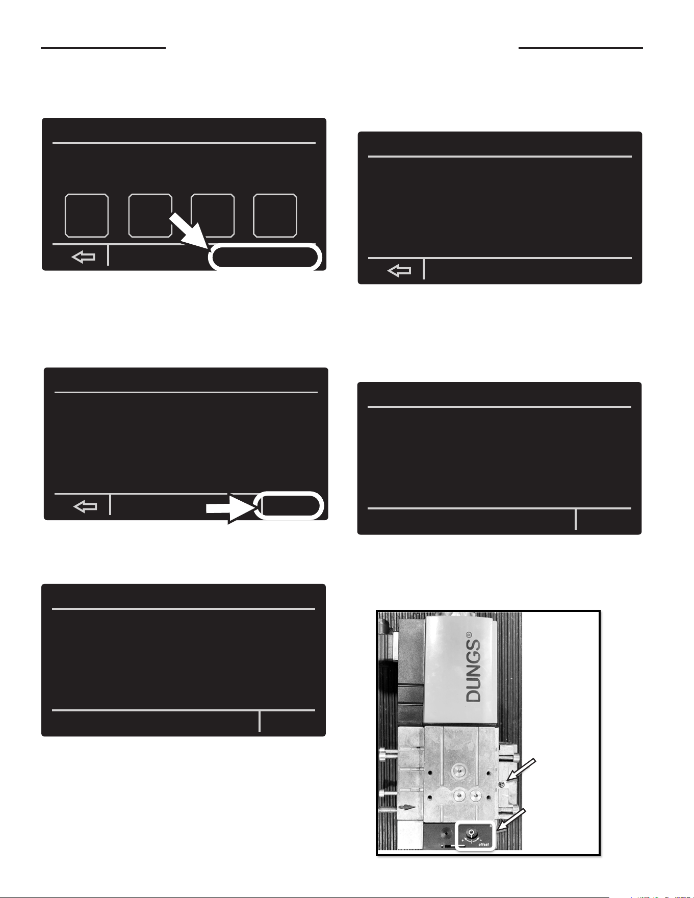
38
Gas Valve GHE119-500 Model ONLY
Inside the Service Menu, there is a button to make
gas valve adjustments.
Pressing the “Gas Valve Adj Test” button will change
the screen to the Test Screen. Confirm the conditions
are met.
Press the “Start Test” button to begin the test.
Once the test is started, the screen will show an ini-
tial “Awaiting Response” message with a countdown
timer.
If the Ignition Control cannot respond, the test will
be ended, and the screen will back out to the Service
Screen for the test to be restarted from the beginning.
After a response from Ignition Control is made, the
screen will transition to the “Running” Screen. The
timer will be set to 10 minutes and begin to count-
down. The tank temperature and fan speed will be
displayed.
Connect CO2 analyzer. After sample is collected and
is a suitable reading, adjust the gas valve by turning
the offset in the appropriate direction. Use a 2.5mm
(3/32”) hex head tool to adjust the gas valve offset.
Gas Valve Adjustments
service
Product Model Number:
Product Serial Number:
Software Version Number:
Gas Valve Adj Test
WH-GHE1-00-01-43
current
alarms
alarm
history
system
health
service
alerts
Gas Valve Adjustment Test
The following conditions must be met to run this test:
1. No active Alarm codes (A-Codes)
2. Mode of Operation = Heating/Disables*
*=Disabled when the Gas Valve Adjustment Test has
already been attempted, not when the Disable
button has been pressed on the main screen
Press Start Test button to initiate test
Start Test
Gas Valve Adjustment Test
Awaiting confirmation from ignition Control...
Time remaining 12 sec.
End Test
Gas Valve Adjustment Test
Ignition control did not respond.
Test Ending.
Gas Valve Adjustment Test
Test Running...
Test Time Remaining: 580 sec.
Upper Tank Temperature 116.5*
Current Fan Speed: 3119 rpm
End Test
Shutter screw used
to adjust CO2% at
full input.
Offset screw used to
adjust CO2% at ignition/
lower speed.
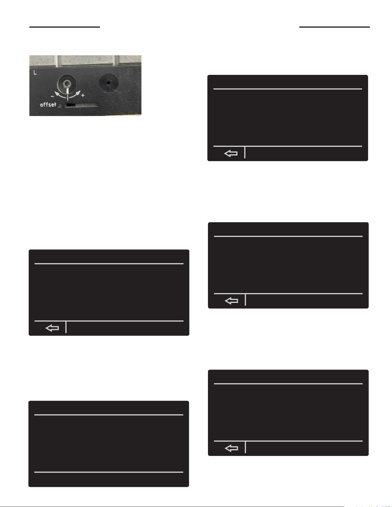
39
Gas Valve GHE119-500 Model ONLY
The target CO2% is from 10-10.8% (2.4-3.8% O2) at
the lower fan speed during the gas valve adjustment
test.
The target CO2% is approximately 9% (5.5% O2)
when the blower is at full input/normal operation. (not
during gas valve adjustment test)
Upon completing any necessary gas valve adjust-
ments, press the “End Test” button to complete the
test, else the test will continue until the timer expires.
If the duration timer expires during the test, the test
timed out, and a message will appear on the screen.
The Ignition Control will transition to Post-Purge be-
fore Disabling, and then the test will end.
Press the back arrow to exit to the service menu.
If, during the gas valve adjustment test, the tank tem-
perature exceeds that of the setpoint temperature,
the test will end. The unit will go into Post-Purge and
a “Heating Cycle Completed” message will appear on
the screen.
Once the Post-Purge is completed, the “Test Com-
pleted” message will appear on the screen.
Press the back arrow to back out of the Test Screen
and go to the Service Screen.
If the ignition control reads “Fault” or “Disabled,” the
test will end, and the corresponding message will ap-
pear.
Press the back arrow to go back to the Service Screen
to continue the test, or power cycle the water heater if
finished
If the “End Test” button is pressed while the test is
running, the test will stop, and the corresponding
message will appear.
The Ignition Control will transition to Disabled, back
out of the Test Screen to go back to the Service
Screen.
Gas Valve Adjustments (Cont.)
Gas Valve Adjustment Test
Test timed out and may not have completed.
Gas Valve Adjustment Test
Heating Cycle Completed - Stopping Test...
Gas Valve Adjustment Test
Test Complete.
If further testing is required, press the back arrow
to return to the Service Screen in order to continue
adjustment of the unit.
If no further testing is required, power cycle
the water heater.
Gas Valve Adjustment Test
System Ended Test.
If further testing is required, press the back arrow
to return to the Service Screen in order to continue
adjustment of the unit.
If no further testing is required, power cycle
the water heater.
Gas Valve Adjustment Test
User Ended Test.
Detailed view
of offset
adjustment
screw.
40
Properly maintained, this water heater will provide years
of dependable, trouble free service. It is strongly
suggested that a regular routine maintenance program
be established and followed by the owner. It is further
recommended that a periodic inspection of the relief
valve and venting system should be made by service
technicians qualified in gas appliance repair.
1. ROUTINE PREVENTIVE MAINTENANCE
A. PRESSURE SWITCH — Inspect the inlet to the
pressure switch and the tubing for debris or
blockage. Clean out the tubing periodically to
prevent buildup of debris.
B COLLECTOR PAN —Remove any particles.
C. CONDENSATE TRAP — Check for blockages.
D. ELECTRICAL CONNECTIONS — Periodic inspection
of all electrical connections and wiring conditions.
For Triton HD, inspect relay to ensure operation of
contacts. Recommend yearly replacement
Label all wires prior to disconnection when servicing
controls. Wiring errors can cause improper and danger-
ous operation.
VERIFY PROPER OPERATION AFTER SERVICING !
Make certain all power to the water heater is turned
"OFF" before performing any maintenance or
inspection work on this water heater.
Before manually operating the relief valve, make certain
no one will be exposed to the danger of coming in contact
with the hot water released by this valve. The water may be
hot enough to create a SCALD hazard. The water released
should be directed to a suitable drain to prevent injury or
damage.
NOTICE: If the temperature and pressure relief
valve on the water heater discharges periodically,
this may be due to thermal expansion in a “closed”
water system. Contact the water supplier or local
plumbing inspector on how to correct this. DO NOT
plug the relief valve outlet.
E. TANK— Good maintenance requires that the tank be
cleaned of deposits. Unless the water supply is soft
(0 to 5 grains hardness), scale or lime deposits will
accumulate in the tank. Hard water scale is deposited
at an increasingly high rate in proportion to increased
water temperature. Accumulation of these deposits
may reduce efficiency, and shorten the life of the
water heater.
Any new installation should have a tank inspection
program set up initially for frequent inspection. The
first inspection should be within a six month period.
Once the scaling tendencies have been established,
the inspection program can be modified to suit the
water conditions. Cleaning should be performed if
the scale has accumulated above the drain valve
opening.
A wet-dry shop vac with a nozzle fashioned from 1”
and/or 3/4” polyethylene pipe makes a good tool for
scraping and removing scale.
TO CLEAN OR INSPECT TANK:
1. Shut off gas valve and drain tank.
2. Remove the tank clean-out cover on the jacket
and, with a pocket knife, cut and remove a circular
plug of insulation the full size of the jacket open-
ing.
3. Loosen the nut on the seal plate assembly enough
to twist the yoke sideways. Hold the assembly se-
curely and push inward, then remove the assembly
from the tank.
4. Remove as much built-up scale from the flue tubes
and the tank bottom as practical. DO NOT allow
the cleaning tool to damage the glass lining.
5. Clean the seal plate and install a new gasket. Wipe
clean the interior surface of the tank that contacts
the gasket. Reinstall the seal plate and tighten
in position. Fill the tank with water and check for
leaks. If no leaks are found, install the insulation
plug and clean-out cover on the jacket and re-light
the water heater.
If chemical lime dissolving cleaners are preferred,
cautiously follow the instructions supplied with the
cleaner. DO NOT use a muriatic or hydrochloric acid
(HCl) base cleaner.
2. SEASONAL OPERATION - If the water heater is to
remain idle for an extended period (60 days or more)
the heater should be turned off. The water heater and
piping should be drained if they might be subjected
to freezing temperatures. It is recommended that the
water heater's operation is thoroughly checked (by a
qualified service technician) before it is placed back
in service. NOTICE: Refer to the Hydrogen Gas
caution notation on page 33.
F. VENTING SYSTEM — Inspect the venting system at
least yearly to make certain the passageways are free
and unobstructed, and that the vent connector from
the water heater’s blower assembly is properly posi-
tioned and securely attached. Remove any obstruc-
tions in the vent connector or vent terminal.
Periodically clean the screens in the vent and air-
inlet terminals (if applicable).
In applicable climates, periodically inspect the vent
and air-inlet terminals to ensure they are not blocked
by snow.
G. BURNER- Cleaning of the burner is not necessary.
Flame rod and ignition cleaning yearly.
H. IGNITOR AND FLAME ROD - Cleaning of the ignitor
and flame rod yearly.
Maintenance
CAUTION
!
CAUTION
!
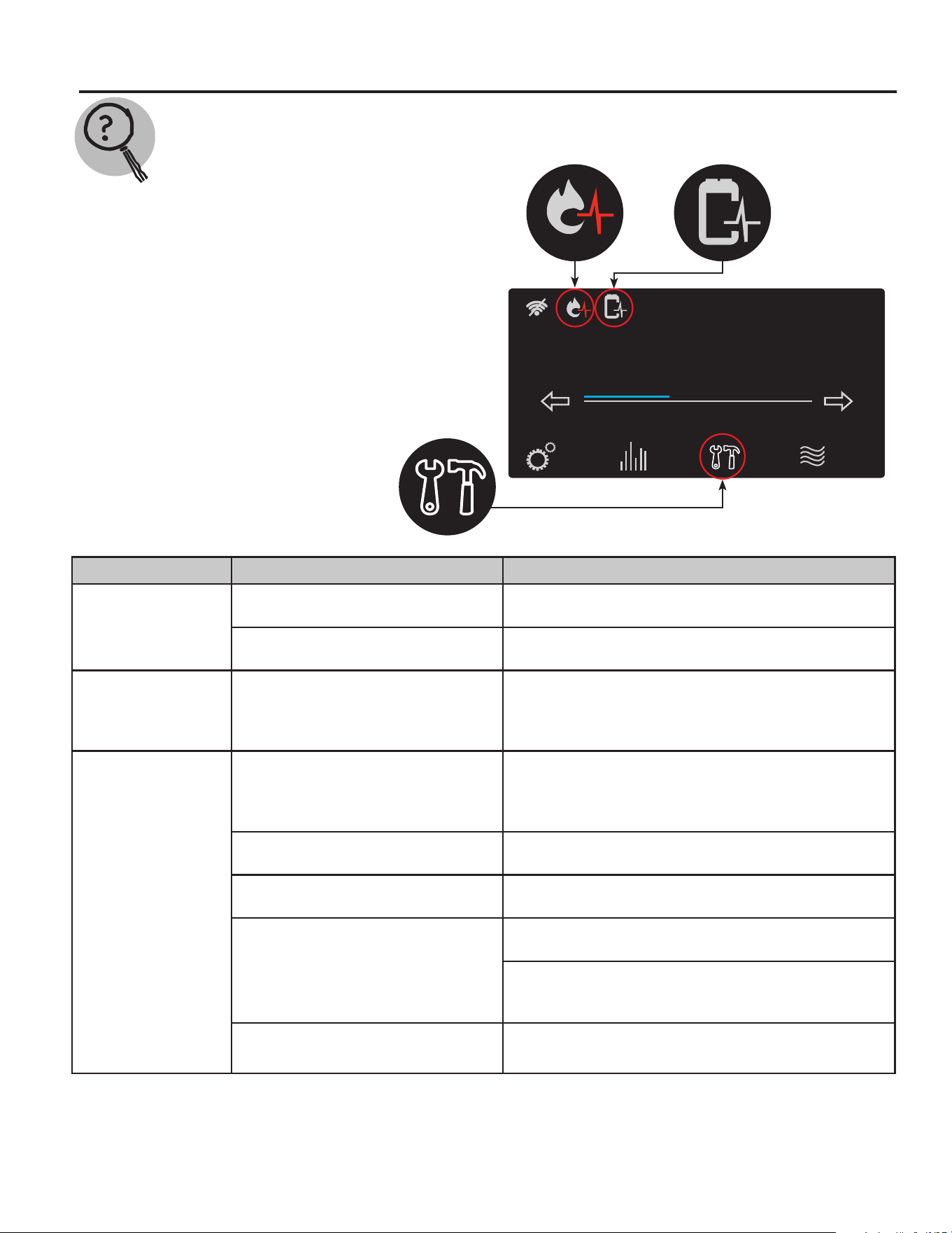
41
Before You Call For Service…
Troubleshooting Tips
Save time and money! Review the charts on the following pages first and you may not
need to call for service.
Problem Possible Causes What To Do
Display not on No power to the unit Check the breaker to the unit, the on/off switch, and
the fuse on the ignition control board.
Harness from control board discon-
nected
Make sure that the wire harness to J4 on the ignition
control board is still connected.
Blower does not run No power to blower motor Verify power to the control board and that all har-
nesses to the blower are properly installed. Make
sure that there is no damage the harnesses or con-
nectors.
Unable to light
the main burner
Air in gas line Let the unit cycle at least 3 times to remove air from
the gas line. If the unit does not try to light, contact a
qualified service technician to purge the air from the
gas line.
Manual gas shut-off
valve(s) not open
Check to make sure that all manual shut-off valves
between the unit and the gas line are open.
Blocked inlet or exhaust vent pipe Contact a qualified service technician to evaluate
vent pipes for a blockage.
Pressure switch
Make sure the pressure switch hoses are not
"kinked" or disconnected.
Blocked inlet or outlet vent systems will cause pres-
sure switch to shut off the unit. Contact a qualified
service technician to evaluate the vent system.
Wire connection not fully secured Contact a qualified service technician to confirm
wire connections.
Status: Standby
StatusSettings
warm hot very hot
Disable
120°
Service
If one of the health indicators is blinking
on the home screen or the service icon is
blinking there is an issue with the operation
of your water heater. Pressing the service
icon will allow you to look at Current Alarms
(and Alerts), Alarm History, and Unit Health
screens for issues that need attention.
Pressing the blinking health indicator will
show the health screen.
Status: Standby
StatusSettings
warm hot very hot
Disable
120°
Service
Status: Standby
StatusSettings
warm hot very hot
Disable
120°
Service
Status: Standby
StatusSettings
warm hot very hot
Disable
120°
Service
42
Make certain power to the water heater is “OFF” before removing the protective cover FOR
ANY REASON.
Label all wires prior to disconnection when servicing controls. Wiring errors can cause
improper and dangerous operation. VERIFY PROPER OPERATION AFTER SERVICING!
For your safety, DO NOT attempt repair of gas piping, gas control burner, vent connectors or
other safety devices. Refer repairs to qualified service personnel.
NOTE: A GHE Training Manual is available through the Technical Services Department for a
more detailed troubleshooting and repair guide.
CAUTION
!
CAUTION
!
CAUTION
!
Before You Call For Service…
Troubleshooting Tips
Save time and money! Review the charts on the following pages first and you may not
need to call for service.
Problem Possible Cause What To Do
Unable to light
the main burner
Gas control problem Contact a qualified service technician.
Unit or electrical supply line not properly
grounded
Verify that the electrical supply line and unit have
proper ground connection.
Main burner does not stay lit
Burner flame not contacting sensor rod.
Call a qualified service technician to review flame
rectification.
Unit or electrical supply line not properly
grounded
Verify the electrical supply line and unit have
proper ground connection.
Not enough or no hot water
Water usage exceeded the capacity
Wait for the water heater to recover after an abnor-
mal demand of the water heater.
Low gas pressure Check the gas supply pressure.
Water heater set point is set too low
See the "User Interface" section of this manual to
the set point temperature.
Leaking or open hot water faucets Make sure all faucets are closed.
"ON/OFF" switch turned off Turn the switch to the "ON" position.
Colder supply water
Incoming water temperature might be lower than
when the unit was initially installed. This will
require a longer heat up cycle.
Burner not staying on Refer to the "Main Burner" section of this manual.
Water is too hot The water heater set point is set too high
See the "User Interface" section of this manual to
the set point temperature.
43
Before You Call For Service…
Alarm (‘A’)
and Alert
(‘T’) Codes
Description Current Alarm Screen Display
A001
Ignition lockout due to a total of 9 consecutive failed
ignitions. This will disable the heater.
A001 Ignition lockout.
->Clear error code by turning the unit o/on. If
problem persists, please contact technical support or
service provider.
A002
Flame not stable lockout. Lost ame three times during
one heat cycle. This will disable the heater.
A002 Flame is not stable.
->Clear error code by turning the unit o/on. If
problem persists, please contact technical support or
service provider.
A003
The intake pressure switch was detected open when
the blower was running. This will disable the heater.
A003 Intake Switch open. Check Wiring/Venting
->Check switch wiring and venting. If problem
persists, please contact technical support or service
provider.
A004
The proof of air ow switch was detected open during
heating operation. This will disable the heater.
A004 PoF Switch error H. Check Blower/Wiring.
->Check switch wiring and venting. If problem
persists, please contact technical support or service
provider.
A005
The proof of air ow switch was detected open during
pre-purge operation. This will disable the heater.
A005 PoF Switch error E. Check Blower/Wiring.
->Check switch wiring and venting. If problem
persists, please contact technical support or service
provider.
A006
The proof of air ow switch was detected open during
post purge operation.
A006 PoF Switch error P. Check Blower/Wiring.
->Check switch wiring and venting. If problem
persists, please contact technical support or service
provider.
A007
Exhaust ue pressure switch was detected open during
heating. This will disable the heater.
A007 Exhaust Switch open. Check Wiring/Venting
->Check switch wiring and venting. If problem
persists, please contact technical support or service
provider.
A008
The proof of air ow pressure switch was detected
closed before the blower started operation. This will
disable the heater.
A008 PoF Switch/Blower mismatch. Call Tech Svc
->The Proof of Fan pressure switch is closed when
the blower is o. Please contact technical support or
service provider.
T009
Gas pressure is below minimum specied. This will
cause diculties lighting the unit.
T009 No Gas detected. Check gas connections
->Verify gas supply to the unit. Check wiring to the
gas pressure switch. If problem persists contact techni-
cal support.
44
Before You Call For Service…
Alarm (‘A’)
and Alert
(‘T’) Codes
Description Current Alarm Screen Display
A016
Energy Cutout (ECO) switch is open. This will disable
the heater.
A016 High Tank Temperature. Call Tech Service.
->Clear error code by pressing clear button. Refer
to use and care manual for troubleshooting, or contact
technical support.
A017
Flue (exhaust) gas temperature has exceeded 155°F.
This will disable the heater.
A017 High Flue Temp. Recycle unit ON/OFF.
->Blower will continue to run until exhaust tempera-
ture has decreased. If problem persists please contact
technical support.
A018
Flue temperature sensor (thermistor) detected open.
This will disable the heater.
A018 Flue Temp Sensor open. Check wiring.
->Check wiring to sensor. If condition persists refer
to use and care manual or contact technical support.
A019
Flue temperature sensor (thermistor) detected short
circuited. This will disable the heater.
A019 Flue Temp Sensor shorted. Call Tech Svc.
->Check wiring to sensor. If condition persists refer
to use and care manual or contact technical support.
T020
Lower tank (inlet) temperature sensor (thermistor)
detected open.
T020 Lower Tank Sensor open. Check wiring.
->Check wiring to sensor. If condition persists refer
to use and care manual or contact technical support.
T021
Lower tank (inlet) temperature sensor (thermistor)
detected short circuited.
T021 Lower Tank Sensor shorted. Call Tech Svc.
->Check wiring to sensor. If condition persists refer
to use and care manual or contact technical support.
A022
Upper tank temperature sensor detected open. This
will disable the heater.
A022 Upper Tank Sensor open. Check wiring.
->Check wiring to sensor. If condition persists refer
to use and care manual or contact technical support.
A023
Upper tank temperature has exceeded 205°F. This will
disable the heater.
A023 Upper Tank temp too hot. Call Tech Svc.
->Clear error code by pressing clear button. Refer
to use and care manual for troubleshooting, or contact
technical support.
A024
Upper tank temperature sensor detected short circuit-
ed. This will disable the heater.
A024 Upper Tank sensor shorted. Call Tech Svc.
->Check wiring to sensor. If condition persists refer
to use and care manual or contact technical support.
45
Before You Call For Service…
Alarm (‘A’)
and Alert
(‘T’) Codes
Description Current Alarm Screen Display
A025
Control does not detect blower RPM. This will disable
the heater.
A025 No Blower RPM feedback. Call Tech Service
->Please contact technical support or service
provider.
A026
Blower RPM feedback (actual RPM) is ≥300 RPM from
desired RPM for > 1 minute.
A026 Blower expected RPM vs actual RPM mismatch
->Please contact technical support or service
provider.
A027
Flame current detected prior to opening gas valve. This
will disable the heater.
A027 Flame present before ignit. Call Tech Svc
->Clear error code by turning the unit o and on. If
problem persists please contact technical support or
service provider.
A028
Flame current detected 10 seconds after closing gas
valve. This will disable the heater.
A028 Flame present w/o heating. Call Tech Svc.
->Clear error code by turning the unit o and on. If
problem persists please contact technical support or
service provider.
A029 Unit did not ignite. A029 Failed ignition. Retrying.
A030 Unit lost ame. A030 Flame lost during heating. Retrying.
A031
Powered anode control is no longer communicating
with the ignition control. This will override any other
anode based alarms.
A031 Powered Anode Communication failure
->Unit will continue to operate. Please contact your
qualied service provider.
T032 Lower (inlet) thermistor analog to digital converter fault.
T032 Lower Tank temp A/D error. Call Tech Svc.
->If problem persists, please contact technical sup-
port or service provider.
A033
Exhaust ue thermistor analog to digital converter fault.
This will disable the heater.
A033 Flue sensor A/D error. Call Tech Service.
->If problem persists, please contact technical sup-
port or service provider.
A034
Upper tank thermistor analog to digital converter fault.
This will disable the heater.
A034 Upper Tank temp A/D error. Call Tech Svc.
->If problem persists, please contact technical sup-
port or service provider.
T035
Gas relay #1 contacts did not close. The unit will contin-
ue to try and close the relay to initiate combustion.
A035 Gas Relay 1 stuck open. Call Tech Service
->If problem persists, please contact technical sup-
port or service provider.
A036
Gas relay #1 stuck closed. This could inadvertently
allow the gas valve to open. This will disable the
heater.
A036 Gas Relay 1 stuck closed. Call Tech Svc.
->If problem persists, please contact technical sup-
port or service provider.
46
Before You Call For Service…
Alarm (‘A’)
and Alert
(‘T’) Codes
Description Current Alarm Screen Display
A037
Gas relay #2 contacts failed to properly close. This can
cause gas valve cycling and gas buildup in the burn
chamber. This will disable the heater.
A037 Gas Relay 2 stuck open. Call Tech Service
->If problem persists, please contact technical sup-
port or service provider.
A038
Gas relay #2 stuck closed. This could inadvertently
allow the gas valve to open. This will disable the
heater.
A038 Gas Relay 2 stuck closed. Call Tech Svc.
->If problem persists, please contact technical sup-
port or service provider.
A039
This is a control board hardware fault and requires con-
trol board replacement if persistent. This will disable
the heater.
A039 Flame sense cct fault. Call Tech Service
->If problem persists, please contact technical sup-
port or service provider.
A040
This is a control board hardware fault and requires con-
trol board replacement if persistent. This will disable
the heater.
A040 Controller RAM fault. Call Tech Service.
->If problem persists, please contact technical sup-
port or service provider.
A041
This is a control board hardware fault and requires con-
trol board replacement if persistent. This will disable
the heater.
A041 Controller ROM fault. Call Tech Service.
->If problem persists, please contact technical sup-
port or service provider.
A042
This is a control board hardware fault and requires con-
trol board replacement if persistent. This will disable
the heater.
A042 Controller EEPROM fault. Call Tech Svc.
->If problem persists, please contact technical sup-
port or service provider.
A043
This is a control board hardware fault and requires con-
trol board replacement if persistent. This will disable
the heater.
A043 IC Program execution fault. Call Tech Svc
->If problem persists, please contact technical sup-
port or service provider.
A044
Input power frequency not 60 Hz. (outside allowable
deviation). This will disable the heater.
A044 Processor Clock/Line Frequency Disagree
->If problem persists, please contact technical sup-
port or service provider.
A101
This is a display board hardware fault and requires con-
trol board replacement if persistent. This will disable
the heater.
A101 Conguration Data Restore Failure
->Initialization of the control system failed at
startup. Please contact technical support or service
provider.
A102 Set the internal clock time.
A102 Time Clock needs to be programmed
->Go to Settings, select time/date menu and set the
time and date.
A103
This is a display board hardware fault and requires con-
trol board replacement if persistent. This will disable
the heater.
A103 Time Clock not advancing time properly
->Please contact your qualied service provider.
A104
Presence of water detected by the leak sensor in the
bottom pan. If water is seen locate source and take ap-
propriate action to correct the issue. This may disable
the heater based on conguration settings.
A104 Water Leak Detected
->The presence of water has been detected by the
control. Please contact a qualied service provider.

47
Before You Call For Service…
Alarm (‘A’)
and Alert
(‘T’) Codes
Description Current Alarm Screen Display
T105
Check to see if leak sensor is installed in the bottom
pan. Check wiring on connector P11 of the ignition
control board.
T105 Water Leak Sensor Not Installed
->Check water leak sensor connection. Refer to use
and care manual for troubleshooting, or contact techni-
cal support.
A108
Communication lost between the display board and the
ignition control board. The ignition control board will
continue to operate the heater using the last known
conguration settings. Check wiring between the dis-
play and P5 of the ignition control board.
A108 Ignition Board Communication Failure
->Communications lost with ignition control board.
If problem persists, contact technical support or service
provider.
A109
CO sensor detects presence of carbon monoxide gas
above the threshold limit. This will disable the heater.
A109 External CO Sensor Alarm: Heater Disabled
->Immediately contact a qualied service provider.
A110
Monthly test of automatic shuto valve (premium mod-
els only) was not completed properly. The valve did not
close in the allotted time.
A110 Shuto Valve Test Close Error
->Auto Shuto valve failed to close during test
cycle. Please contact technical support or service
provider.
A111
Monthly test of automatic shuto valve (premium mod-
els only) was not completed properly. The valve did not
open in the allotted time. This will disable the heater.
A111 Shuto Valve Test Open Error
->Water heater has been disabled. Manually open
valve. Please contact technical support or service
provider.
A112
Automatic shuto valve (premium models only) is
closed. This will disable the heater.
A112 Shuto Valve Not Open: Heating Disabled
->Manually open valve if no water detected or if
unit is not being serviced. Contact technical support or
service provider.
T113
Peak ame rod current has deviated from the startup
average. This is indicative of degradation of the ame
rod (dirty, sooty). It needs to be cleaned and inspected .
T113 Flame Rod Degraded and Needs Servicing
->Clean or replace per use and care manual.
Please contact technical support for assistance.
T114
Peak ame rod current has deviated from the startup
average by a signicant amount. Clean and inspect
ame rod. Replace if necessary.
T114 Flame Rod Degraded and Needs Servicing
->Clean or replace per use and care manual.
Please contact technical support for assistance.
A115
Monitored characteristics of the combustion system
indicate degraded performance. Combustion system
needs to be inspected and serviced.
T115 Combustion Health Degraded: Needs Service
->Combustion system performance is degraded.
Please contact technical support or service provider for
assistance.
A116
Monitored characteristics of the combustion system
indicate severely degraded performance. Combustion
system needs to be inspected and serviced.
T116 Combustion Health Degraded. Needs Service
->Clear error code by pressing clear button. Refer
to use and care manual for troubleshooting, or contact
technical support.
48
Before You Call For Service…
Alarm (‘A’)
and Alert
(‘T’) Codes
Description Current Alarm Screen Display
T117
Periodic maintenance, inspection, and upkeep on the
unit.
T117 Time to Drain and Inspect Tank
->Refer to the use and care manual for instructions,
or contact technical support or service provider.
T118
Periodic maintenance, inspection, and upkeep on the
unit.
T118 Time to Check Venting for Debris
->Refer to the use and care manual for information,
or contact technical support or service provider.
T119
Periodic maintenance, inspection, and upkeep on the
unit.
T119 Time to Clean Out the Condensate Drain Trap
->Refer to the use and care manual for instructions
and locations. Call technical support or service provider
if necessary.
T120
Periodic maintenance, inspection, and upkeep on the
unit.
T120 Time to Replace the Neutralizer
->Clear error code by pressing clear button. Refer
to use and care manual for troubleshooting, or contact
technical support.
A121
One or more powered anodes do not sense water in
the tank. This can also be caused by an “open” circuit
on an anode. Check anode wiring. Ensure tank is com-
pletely full. This will disable the heater.
A121 No Water Detected in Tank
->Fill the tank with water. If error persists, please
contact technical support or service provider.
T122
No communication with the powered anode controller
for >60 seconds. If the green LED on top of the anode
control is solid, the anodes are still protecting the tank.
T122 Powered Anode Control Comm Failure
->Check wiring connections of the anode control
board. If error persists, please contact technical support
or service provider.
T123
Anode “open” circuit. This can be caused by wiring
damage, wiring disconnected, or anode damage.
T123 Upper Anode Open
->Check wiring connections for the upper anode.
If error persists, please contact technical support or
service provider.
T124
Anode control common and the power connection for
this anode cross connected.
T124 Upper Anode Mounting Error
->Check wiring connections for the upper anode.
If error persists, please contact technical support or
service provider.
T125
Anode “short” circuited. This can be caused by wiring
damage, anode damage, or the anode in contact with
the tank.
T125 Upper Anode Shorted
->Check wiring connections for the upper anode.
If error persists, please contact technical support or
service provider.
T126
Anode power = 100%. The anode system has reached
its protective limits on one or more anode elements.
T126 Upper Anode Overload
->Upper Anode has reached full capacity. Tank may
not be fully protected. Please contact technical support
or service provider.
T127
Anode power > 70%. The anode system is approaching
its protective limits on one or more anode elements.
T127 Upper Anode Pre-Overload
->Upper Anode near end of useful life but will con-
tinue protecting tank. Please contact technical support.
T128
Anode “open” circuit. This can be caused by wiring
damage, wiring disconnected, or anode damage.
T128 Middle Anode Open
->Check wiring connections for the middle anode.
If error persists, please contact technical support or
service provider.
T129
Anode control common and the power connection for
this anode cross connected.
T129 Middle Anode Mounting Error
->Check wiring connections for the middle anode.
If error persists, please contact technical support or
service provider.
49
Before You Call For Service…
Alarm (‘A’)
and Alert
(‘T’) Codes
Description Current Alarm Screen Display
T130
Anode “short” circuited. This can be caused by wiring
damage, anode damage, or the anode in contact with
the tank.
T130 Middle Anode Shorted
->Check wiring connections for the middle anode.
If error persists, please contact technical support or
service provider.
T131
Anode power = 100%. The anode system has reached
its protective limits on one or more anode elements.
T131 Middle Anode Overload
->Middle Anode has reached full capacity. Tank
may not be fully protected. Contact technical support or
service provider.
T132
Anode power > 70%. The anode system is approaching
its protective limits on one or more anode elements.
T132 Middle Anode Pre-Overload
->Middle Anode near end of useful life but will con-
tinue protecting tank. Please contact technical support.
T133
Anode “open” circuit. This can be caused by wiring
damage, wiring disconnected, or anode damage.
T133 Lower Anode Open
->Check wiring connections for the upper anode.
If error persists, please contact technical support or
service provider.
T134
Anode control common and the power connection for
this anode cross connected.
T134 Lower Anode Mounting Error
->Check wiring connections for the lower anode.
If error persists, please contact technical support or
service provider.
T135
Anode “short” circuited. This can be caused by wiring
damage, anode damage, or the anode in contact with
the tank.
T135 Lower Anode Shorted
->Check wiring connections for the lower anode.
If error persists, please contact technical support or
service provider.
T136
Anode power = 100%. The anode system has reached
its protective limits on one or more anode elements.
T136 Lower Anode Overload
->Lower Anode has reached full capacity. Tank may
not be fully protected. Contact technical support or
service provider.
T137
Anode power > 70%. The anode system is approaching
its protective limits on one or more anode elements.
T137 Lower Anode Pre-Overload
->Lower Anode near end of useful life but will con-
tinue protecting tank. Please contact technical support.
T138
Anode “open” circuit which could be caused by wiring
damage, wiring disconnected or anode damage.
T138 Anode 4 Open
->Check wiring connections for anode #4. If error
persists, please contact technical support or service
provider.
T140
Anode “short” circuited which could be caused by wiring
damage, anode damage or the anode is in contact with
the tank. This is not a connector issue and not caused
from leaking. This can only be a failed anode.
T140 Anode 4 Shorted
->Check wiring connections for anode #4. If error
persists, please contact technical support or service
provider.
T141
Anode power ≥ 100% and has reached its protective
limit.
T141 Anode 4 Overload
->Anode #4 has reached full capacity. Tank may not
be fully protected. Contact technical support or service
provider.
T142
Anode power > 87% but < 100%. The anode is ap-
proaching its protective limit.
T142 Anode 4 Pre-Overload
->Anode #4 has reached full capacity. Tank may not
be fully protected. Contact technical support or service
provider.
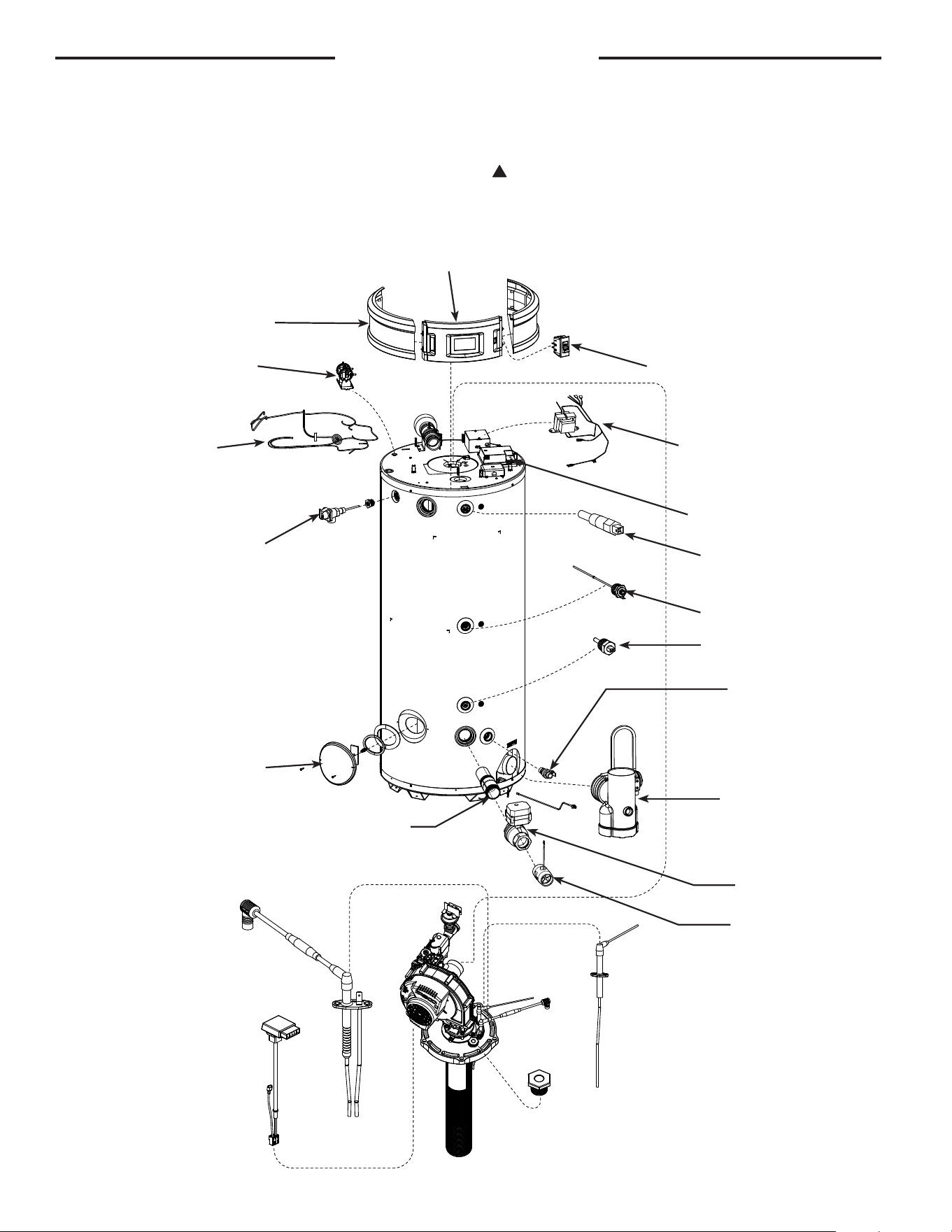
50
Replacement Parts
Instructions For Placing a Parts Order
All parts orders should include:
The model and serial number of the water heater
from the rating plate.
Specify type of gas (natural or LP) as marked on
the rating plate.
Part description (as noted below) and number of
parts desired.
!
CAUTION: For your safety DO NOT attempt repair of gas piping,
gas control burner, vent connectors or other safety devices. Refer
repairs to qualified service personnel.
Flame Sensor Kit
Control Board
Display Kit
Relief Valve
Water Temperature and
ECO Probe
Power Anode
Lower Thermostat
Transformer Wire Harness
Hand Hole
(under cover)
Drain Valve
Exhaust Tee
Assembly
Water Flow Sensor
(SS Only)
Auto Shut-off
(SS Only)
Diffuser Nipple
On / Off Switch
POF & Intake
Pressure switch
Side Panel Covers
Top Pan Wire
Harness
Blower / Gas Valve /
Burner Assembly Kit
Igniter Kit
GHE80SS, GHE80SU
GHE100SS, GHE100SU
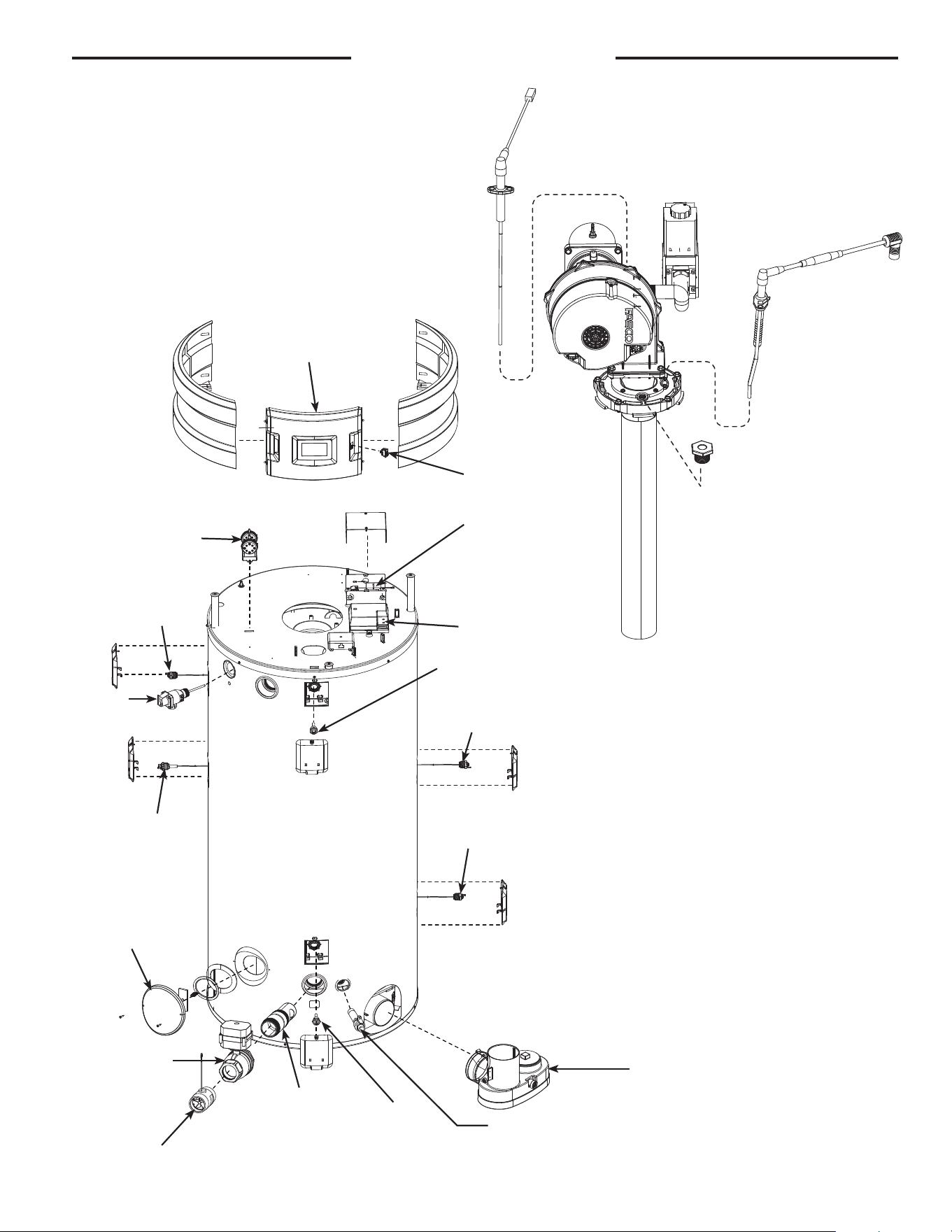
51
Water Flow Sensor
(SS Only)
Auto Shut-off
(SS Only)
Diffuser
Nipple
Replacement Parts
Flame Sensor Kit
Control Board
Display Kit
Relief
Valve
Water Temperature and
ECO Probe
Power Anode
Power Anode
Power Anode
Power Anode
Lower
Thermostat
Transformer
Wire Harness
Hand Hole
(under cover)
Drain Valve
Exhaust Tee
Assembly
On / Off Switch
POF & Intake
Pressure switch
Blower / Gas Valve /
Burner Assembly Kit
Igniter Kit
GHE119SS, GHE119SU
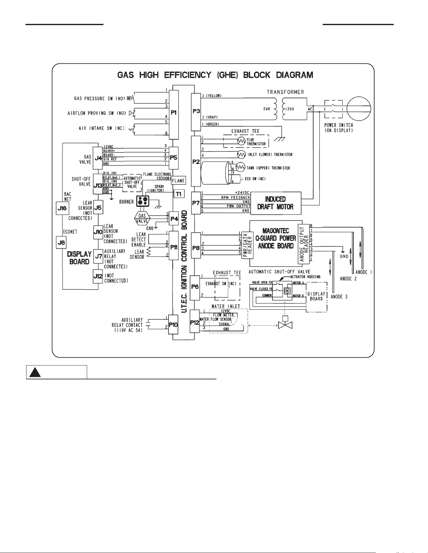
52
Wiring and Schematic Diagrams
Label all wires prior to disconnection when servicing controls. Wiring errors can cause improper and dangerous operation VERIFY PROPER
OPERATION AFTER SERVICING!
CAUTION
!
AX5631
GHE80/100 Diagram
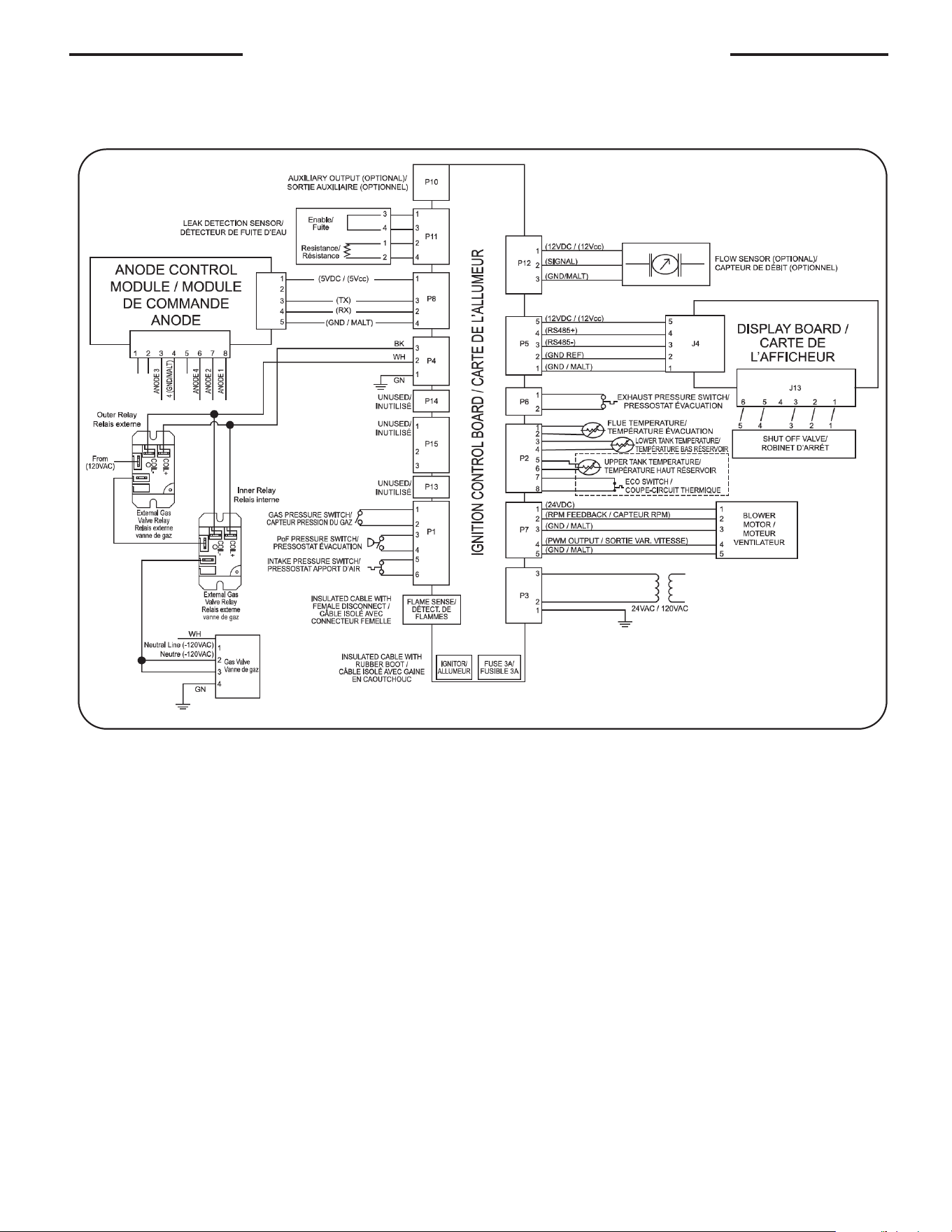
53
Wiring and Schematic Diagrams
GHE119 Diagram

54
Important Instructions for the Commonwealth of Massachusetts
The Commonwealth of Massachusetts requires com-
pliance with regulation 5.08: Modifications to NFPA-
54, Chapter 10 : 248 CMR 4.00 and 5.00 for installation
of through – the – wall vented gas appliances as fol-
lows:
(1) Revise NFPA-54 section 10.5.4.2 by adding a sec-
ond exception as follows:
Existing chimneys shall be permitted to have their use
continued when a gas conversion burner is installed,
and shall be equipped with a manually reset device
that will automatically shut off the gas to the burner in
the event of a sustained back-draft.
(2) Revise 10.8.3 by adding the following additional
requirements:
(a) For all side wall horizontally vented gas fueled
equipment installed in every dwelling, building or
structure used in whole or in part for residential pur-
poses, including those owned or operated by the
Commonwealth and where the side wall exhaust vent
termination is less than seven (7) feet above finished
grade in the area of the venting, including but not lim-
ited to decks and porches, the following requirements
shall be satisfied:
1. INSTALLATION OF CARBON MONOXIDE DETEC-
TORS. At the time of installation of the side wall hori-
zontal vented gas fueled equipment, the installing
plumber or gasfitter shall observe that a hard wired
carbon monoxide detector with an alarm and battery
back-up is installed on the floor level where the gas
equipment is to be installed. In addition, the installing
plumber or gasfitter shall observe that a battery oper-
ated or hard wired carbon monoxide detector with
an alarm is installed on each additional level of the
dwelling, building or structure served by the side wall
horizontal vented gas fueled equipment. It shall be the
responsibility of the property owner to secure the ser-
vices of qualified licensed professionals for the instal-
lation of hard wired carbon monoxide detectors
a. In the event that the side wall horizontally vented
gas fueled equipment is installed in a crawl space or
an attic, the hard wired carbon monoxide detector
with alarm and battery back-up may be installed on
the next adjacent floor level.
b. In the event that the requirements of this subdi-
vision can not be met at the time of completion of
installation, the owner shall have a period of thirty (30)
days to comply with the above requirements; pro-
vided, however, that during said thirty (30) day period,
a battery operated carbon monoxide detector with an
alarm shall be installed.
2. APPROVED CARBON MONOXIDE DETECTORS.
Each carbon monoxide detector as required in accor-
dance with the above provisions shall comply with
NFPA 720 and be ANSI/UL 2034 listed and IAS certi-
fied.
3. SIGNAGE. A metal or plastic identification plate
shall be permanently mounted to the exterior of the
building at a minimum height of eight (8) feet above
grade directly in line with the exhaust vent terminal for
the horizontally vented gas fueled heating appliance
or equipment. The sign shall read, in print size no less
than one-half (1/2) inch in size, "GAS VENT DIRECTLY
BELOW. KEEP CLEAR OF ALL OBSTRUCTIONS".
4. INSPECTION. The state or local gas inspector of
the side wall horizontally vented gas fueled equipment
shall not approve the installation unless, upon inspec-
tion, the inspector observes carbon monoxide detec-
tors and signage installed in accordance with the pro-
visions of 248 CMR 5.08(2)(a)1 through 4.
(b) EXEMPTIONS: The following equipment is exempt
from 248 CMR 5.08(2)(a)1 through 4:
1. The equipment listed in Chapter 10 entitled "Equip-
ment Not Required To Be Vented" in the most current
edition of NFPA 54 as adopted by the Board; and
2. Product Approved side wall horizontally vented
gas fueled equipment installed in a room or structure
separate from the dwelling, building or structure used
in whole or in part for residential purposes.
(c) MANUFACTURER REQUIREMENTS - GAS EQUIP-
MENT VENTING SYSTEM PROVIDED. When the
manufacturer of Product Approved side wall horizon-
tally vented gas equipment provides a venting system
design or venting system components with the equip-
ment, the instructions provided by the manufacturer
for installation of the equipment and the venting sys-
tem shall include:
1. Detailed instructions for the installation of the vent-
ing system design or the venting system components;
and
2. A complete parts list for the venting system design
or venting system.
(d) MANUFACTURER REQUIREMENTS - GAS EQUIP-
MENT VENTING SYSTEM NOT PROVIDED. When the
manufacturer of a Product Approved side wall hori-
zontally vented gas fueled equipment does not pro-
vide the parts for venting the flue gases, but identifies
"special venting systems", the following requirements
shall be satisfied by the manufacturer:
1. The referenced "special venting system" instruc-
tions shall be included with the appliance or equip-
ment installation instructions; and
2. The "special venting systems" shall be Product
Approved by the Board, and the instructions for that
system shall include a parts list and detailed installa-
tion instructions.
(e) A copy of all installation instructions for all Prod-
uct Approved side wall horizontally vented gas fueled
equipment, all venting instructions, all parts lists for
venting instructions, and/or all venting design instruc-
tions shall remain with the appliance or equipment at
the completion of the installation.

55
Notes

56
The following Gasket is required for tank cleanout maintenance for all models:
SP5886 Tank Handhole Sealplate Gasket
All other Parts can be ordered by providing the following information:
1. Description of Part(s), such as:
Gas Valve
Igniter
Burner
Switch/Sensor
Blower Assembly
Anode Rods
Or other parts as required (see replacement parts section).
2. Quantity of each part required.
3. Complete model number and name of the water heater.
4. Serial Number of water heater.
5. Specify Type of Gas.
6. Address Parts Orders to your distributor or dealer.
NOTICE: For installations requiring NSF 5 compliance, order kit AS42690A or B to meet sealing
requirements and NSF 5 label.
1. Should you have any questions about your new
water heater, or if it requires adjustment, repair,
or routine maintenance, it is suggested that you
first contact your installer, plumbing contractor or
previously agreed upon service agency. In the event
that the firm has moved, or is unavailable, refer to
the telephone directory commercial listings or local
utility for qualified service assistance.
2. Should your problem not be solved to your
complete satisfaction, you should then contact the
Manufacturer’s National Service Department at one
of the following addresses:
In The U.S.A.:
Rheem Manufacturing Co., Water Heater Division
ATTN: Technical Service
800 Interstate Park Drive
Montgomery, AL 36109
Phone: 1-800-432-8373
In CANADA:
Rheem Canada, Ltd. / Ltée
125 Edgeware Road, Unit 1
Brampton, ON L6Y 0P5
Phone: 1-800-268-6966.
When contacting the manufacturer, the following
information should be made available:
a. Model and serial numbers of the water heater as
shown on the rating plate attached to the jacket
of the heater.
b. Address where the water heater is located and
can be seen.
c. Name and address of the installer and any ser-
vice agency who performed service on the water
heater.
d. Date of original installation and dates any service
work was performed.
e. Details of the problem as you can best describe
them.
f. List of people, with dates, who have been
contacted regarding your problem.
How to Obtain Service Assistance