Form No. Z3023
Rev. 02.23.26
G5 INSTALLATION &
OPERATION MANUAL
*Commerical UC
series models only.


8300 W. Good Hope Rd. Milwaukee, WI 53223 • (800) 558-5592 • perlick.com
CUSTOMER INSTALLATION REVIEW CHECKLIST
IMPORTANT: TO ENSURE A SAFE AND PROPER INSTALLATION,
REVIEW BELOW ITEMS DIRECTLY WITH INSTALLER.
IMPORTANT
Has all shipping tape, string and packing been removed?
Has the unit been secured in place with the provided anti-tip bracket or
is the unit 1” or less from a solid soft?
Are all levelers (15” and 24” qty. 4) extended down to make contact with the
oor?
Is the unit level?
Is the power cord connected directly into a properly grounded 3-prong outlet
in accordance with all applicable local codes?
Has all stainless paper been removed?
Are the panel(s) (wood overlays if used) attached securely and
properly aligned?
Have all the product accessories been installed?
Has the unit been registered on our web site at www.perlick.com? Click on
“Residential” or “Commercial”, then “Resources”. Click on the link “Warranty
and Support”. You must complete and submit this form or the installation date
will revert back to the ship date.
Have the stainless steel door(s) been inspected for imperfections?
NOTE: This is to be completed by the dealer/installer with the customer at
installation completion.
Has the time and date been set on the control?
►
►
►
►
►
►
►
►
►
►
►
ONCE CHECKLIST IS COMPLETE, ALLOW THE UNIT TO OPERATE FOR AT LEAST 24 HOURS
BEFORE LOADING PRODUCTS OR ADJUSTING TEMPERATURE SETTINGS.

G5 User Installation & Operation Manual
4
TABLE OF CONTENTS
General Information ........................................................................................................................................................................ 5
Introduction................................................................................................................................................................................... 5
Warranty ........................................................................................................................................................................................ 5
Safety ................................................................................................................................................................................................... 5
Refrigerant .................................................................................................................................................................................... 6
Installation Preparation .................................................................................................................................................................. 7
Environmental Operation......................................................................................................................................................... 7
Space Requirements ................................................................................................................................................................. 7
Plumbing Requirements .......................................................................................................................................................... 8
Electrical Requirements ........................................................................................................................................................... 8
Uncrating and Inspection ........................................................................................................................................................ 9
Anti Tip Installation .................................................................................................................................................................... 9
Door Orientation and Overlay ............................................................................................................................................ 10
Overlay Installation and Removal ................................................................................................................................ 10
Hinge Direction ................................................................................................................................................................... 11
Installation ........................................................................................................................................................................................ 12
Placing Unit ................................................................................................................................................................................ 12
Leveling Unit .............................................................................................................................................................................. 12
Front Grill Installation ............................................................................................................................................................. 12
Shelving and Drawer ............................................................................................................................................................. 12
Shelf and Drawer Weight Limits .................................................................................................................................... 12
Shelving Installation and Adjustment .......................................................................................................................... 12
Drawer Removal and Installation................................................................................................................................... 12
Power Unit On ........................................................................................................................................................................... 13
Loading Product ................................................................................................................................................................... 13
Controls ............................................................................................................................................................................................. 13
Display Icon Denitions and Operations ........................................................................................................................ 13
Controller Operation .............................................................................................................................................................. 15
Master Switch ....................................................................................................................................................................... 15
Display ..................................................................................................................................................................................... 15
Standby Mode ...................................................................................................................................................................... 15
Interior Light .......................................................................................................................................................................... 15
Quick Cool .............................................................................................................................................................................. 15
Display Lock .......................................................................................................................................................................... 15
Sabbath Mode ...................................................................................................................................................................... 15
Display Button Sound ........................................................................................................................................................ 15
Select Unit of Measurement for Display Temperature ......................................................................................... 15
Defrost Operation ................................................................................................................................................................ 16
Return from Sub Menu ...................................................................................................................................................... 16
Changing Temperature ..................................................................................................................................................... 16
Time and Date ...................................................................................................................................................................... 16
Changing Humidity Percentage .................................................................................................................................... 16
Alarm History ........................................................................................................................................................................ 17
Show Room Mode .............................................................................................................................................................. 17
Diagnostic Window ............................................................................................................................................................ 17
Maintenance and Care ............................................................................................................................................................... 18
Cleaning the Condenser .................................................................................................................................................. 18
Seasonal Maintenance For Unit Located Outdoor ..................................................................................................... 18
Winterizing ............................................................................................................................................................................. 18
Spring Start-Up .................................................................................................................................................................... 18
Led Replacement .................................................................................................................................................................... 19
G5 Installation & Operation Manual
Perlick is committed to continuous improvement. Therefore, we reserve the right to change specications without prior notice.
5
Form No. Z3023
Rev. 02.23.26
Serial Number is located on the inside nameplate
on top center of the cabinet.
Model Number:_______________________________
Serial Number: ______________________________
Purchase Date:________________________________
Dealer Name & Address:
______________________________________________
______________________________________________
Phone Number: ________________________________
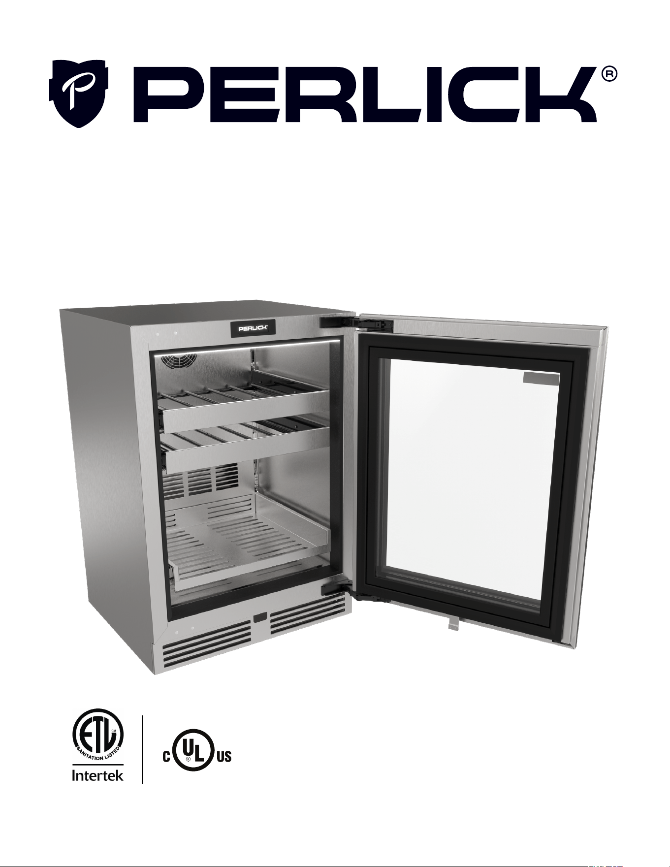
GENERAL INFORMATION
Introduction
Congratulations on your purchase of a Perlick
undercounter product. This manual has been
prepared to assist you in the installation of your
cabinet and to acquaint you with its operation and
maintenance.
We dedicate considerable time to ensure that our
products provide the highest level of customer
satisfaction. If service is required, your dealer can
provide you with a list of qualied service agents.
For your own protection, never return merchan-
dise for credit without our approval.
We thank you for selecting a Perlick product
and assure you of our continuing interest in your
satisfaction.
Warranty
Improper installation of this product may void
warranty. Please review this manual for recom-
mended installation. All warranty service will
need to be performed by a Perlick-authorized
service agent utilizing OEM parts.
To register your product, visit our web site at
www.perlick.com. Click on “Residential” or “Com-
mercial”, then “Resources”. Click on the link
“Warranty and Support”. You must complete and
submit this form or the installation date will revert
back to the ship date.
Please record the purchase date and the dealer’s
name, address and telephone number below.
SAFETY
PLEASE READ all instructions completely before
attempting to install or operate the unit. Take
particular note of the DANGER, WARNING, an
CAUTION information in the manual. The infor-
mation is important for the safe and efcient
installation, operation and care of your Perlick unit.
DANGER
Indicates a hazard that WILL
result in serious injury or
death if precautions are not followed.
WARNING
Indicates a hazard MAY
cause serious injury or
death if precautions are not followed.
CAUTION
Indicates a hazard where
minor injury or product
Stainless Steel Care & Cleaning ........................................................................................................................................ 19
Trouble Shooting ..................................................................................................................................................................... 21
Alarms and Faults ................................................................................................................................................................... 21
Service and Repairs ................................................................................................................................................................... 22
Service ......................................................................................................................................................................................... 22
Repairs ......................................................................................................................................................................................... 22
Decommissioning and Disposal ............................................................................................................................................ 24
Decommissioning and Disposal – (End of Life) .......................................................................................................... 24
Labels ........................................................................................................................................................................................... 25
G5 User Installation & Operation Manual
Perlick is committed to continuous improvement. Therefore, we reserve the right to change specications without prior notice.
6
damage may occur if precautions are not followed.
NOTICE
Indicates property damage
MAY occur if warnings or
instructions are not followed.
The GHS pictogram diamond symbol indi-
cates this product contains a ammable gas.
This symbol is used within this manual and labels
on the appliance.
The red ame triangle symbol indicates this
product contains a ammable gas. This
symbol is used within this manual and labels on
the appliance.
Refrigerant
CAUTION
This product contains a
ammable refrigerant,
R600a (Isobutane). The appliance shall be
installed in accordance with the safety standard
for refrigeration systems, ANSI/ASHRAE 15. All
local, state, provincial, and federal laws must be
followed for installation, handling, servicing, and
disposal of the appliance.
R600a (isobutane) is a ammable refrigerant and
hydrocarbon. This product has been designed
to operate safely with R600a and is certied
to safety standards UL/CSA 60335-1, UL/CSA
60335-2-24, and UL/CSA 60335-2-89.
•
R600a is heavier than air. The concentration
will always be highest at the oor level.
• The explosion limits are as follows:
○ Lower Limit: 1.8% by volume
○ Upper Limit: 8.4% by volume
○ Ignition Temperature: 460°C
DANGER
Take caution when handling,
moving and using the product
to avoid damaging the refrigerant tubing or
increasing the risk of a leak.
WARNING
Only service personnel that
have the proper qualica-
tions and training to safely work with ammable
refrigerants and electricity should attempt to
maintain, service, or repair the refrigeration and
electrical system of this appliance. This includes
but is not limited to breaking into the refrigeration
circuit, opening of covers and enclosures, and
service or repair any components of the electrical
system.
W ARNING
If service is necessary, it is
recommended that repair
work is performed by a Perlick authorized ser-
vicer. Work done by unqualied individuals could
potentially be dangerous and will void the
warranty.
NOTICE
This product contains blown
foam insulation using blow-
ing agent R611 (Methyl Formate). The foam in
this product does not contain HFC’s, CFC’s, or
HCFC’s.
CAUTION
This product uses R611 as a
blowing agent for the foam
insulation. R611 is mildly ammable. All local,
state, provincial, and federal regulations must be
followed when disposing of the appliance.
WARNING: California Prop 65 Notice
These products may expose you to chemicals
including Chromium, which are known to the state
of California to cause cancer and birth defects
or other reproductive harm. For more information
on whether a product in this list contains these
chemicals, please refer to the specic product
page at perlick.com. Or to nd out more about
Prop 65, go to P65Warnings.ca.gov.
IMPORTANT!
Read and understand all information in this manual before attempting the installation.
All plumbing and electrical work must be performed by a qualied technician and conform to all applicable
state and local codes.
Keep hands away from pinch points on the equipment. For example, any area around the door hinges.
This appliance is not intended for use by persons (including children) with reduced physical, sensory or
mental capabilities, or lack of experience and knowledge, unless they have been given supervision or
instruction concerning use of the appliance by a person responsible for their safety.
Children should be supervised to ensure that they do not play with the appliance.
G5 Installation & Operation Manual
Perlick is committed to continuous improvement. Therefore, we reserve the right to change specications without prior notice.
7
Form No. Z3023
Rev. 02.23.26
INSTALLATION PREPARATION
Environmental Operation
Coastal grade units are recommended for installations within 1 mile of the coast, but also up to 5 miles
of the coast depending on local conditions. Coastal grade units are recommended if installed near a
pool but are needed if installed near an indoor pool. Use of non-coastal grade unit may impact perfor-
mance and may void warranty.
Application Freezer Refrigerator/Beverage Wine
Lower Ambient Temperature 32 °F
0 °C
38 °F
3 °C
42 °F
5°C or below set point
Upper Ambient Temperature 105 °F
41 °C
105 °F
41 °C
105 °F
41 °C
NOTE: When environmental temperatures are below the lower ambient temperature limit reference Winter-
ization in Maintenance section to prepare unit for winter storage. Once temperatures are above the lower
ambient temperature limit, then reference the Spring Start-Up in Maintenance section.
Use outside of these conditions will have signicant impact to performance, risk damaging the equipment,
and may void warranty.
NOTE: Glass door units may sweat in conditions
with relative humidity exceeding 75%.
This product identication label is marked as cli-
matic class 5. This product has been tested in test
room conditions of an ambient of 109° F (43° C).
Space Requirements
To ensure maximum performance, fresh air must
be allowed to circulate through the machinery
compartment. Do not place anything in front of
the cabinet that would obstruct air ow at the
grill. Do not place the unit in an unventilated small
room.
NOTICE
If the unit is installed under a
countertop, it is recom-
mended that the countertop be supported by
surrounding cabinetry and use shims to support
countertop directly above the refrigerated
cabinet.
NOTICE
Make sure the oor under the
unit is level with the sur-
rounding nished oor. Protect a nished oor
with plywood, cardboard, or some other suitable
material before moving the unit into place. Failure
to do this may result in damage to the oor.
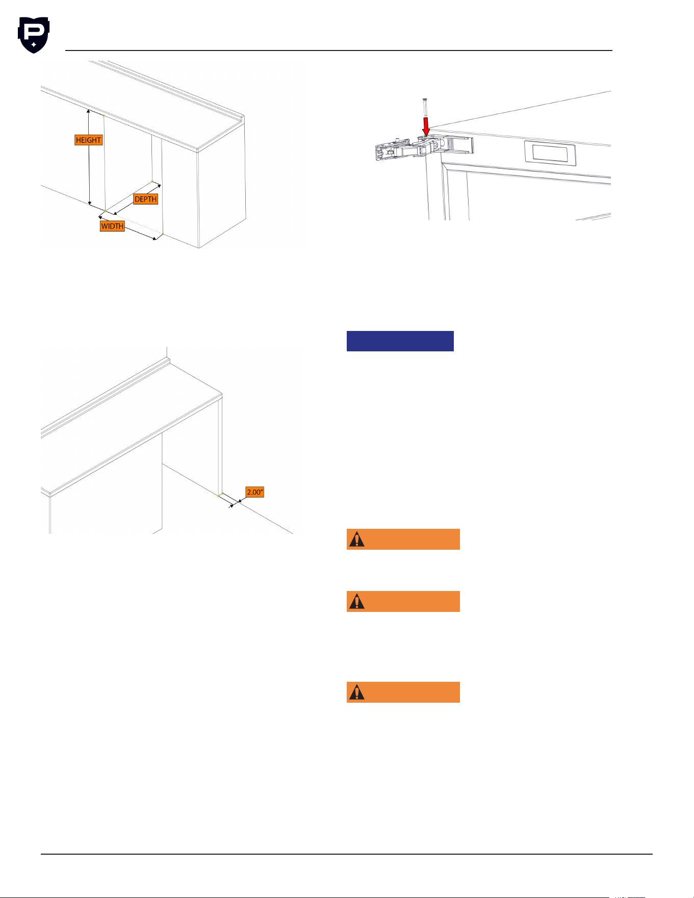
NOTE: Make sure the space opening is correctly
sized for the unit. See chart below for nished
rough opening requirements:
15” Standard Height
Height Depth Width
34-7/8” minimum
35-1/2” maximum
24” 15”
24” Standard Height
Height Depth Width
34-7/8” minimum
35-1/2” maximum
24” 24”
24” Shallow Depth
Height Depth Width
32-1/2” 18” 24”
24” ADA-Compliant Series
Height Depth Width
32-1/2” 24” 24”
G5 User Installation & Operation Manual
Perlick is committed to continuous improvement. Therefore, we reserve the right to change specications without prior notice.
8
NOTE: For a cabinet door to open properly, the
door must open a minimum of 90°. Use a mini-
mum 2” ller in corner installations to assure a
full 90° opening. Allow 25” clearance in front of
unit for full door swing and shelf/drawer pull out
for all units.
Perlick doors open to 115°. When installing a
panel thicker than ¾”, or if located next to adja-
cent wall, the 90° hinge stop pin may be required
to prevent damage to the unit and adjacent cabi-
netry/walls. This hinge pin must be installed prior
to full integration.
1. Remove the cabinet hinge trim cover.
2. Open cabinet door approximately 45° to 85°
to expose the hinge pin hole under hinge
guard. Install the hinge pin into hole. Ensure
hinge pin is fully seated to top of hinge to
prevent damage to hinge guard.
3. Reattach the cabinet hinge trim piece.
Check that the following are level and square:
• Front and interior opening
• Installation opening and oor surface
• Countertop bottom front edge
NOTE: The oor under the unit must be at the
same level as the surrounding nished oor.
NOTICE
To prevent possible damage
to the countertop, do not
place heavy objects on countertop directly over
unit.
Plumbing Requirements
No plumbing connections are required. Con-
densate from the cooling coil is automatically
evaporated through a condensate pan located in
the condensing section of the unit.
Electrical Requirements
For specications, see data plate located on the
cabinet.
WARNING
Electrical work must be per-
formed by a qualified
technician and conform to all applicable state and
local codes.
WARNING
Inspect the electrical cord
and plug for damage prior
to energizing the unit to avoid potential electric
shock. If the power supply cord is damaged, it
must be replaced by a qualied service agent and
with an OEM replacement power supply cord.
WARNING
Use electrical grounding to
avoid electrocution or elec-
tric shock. This appliance is equipped with a
3-prong (grounding) polarized plug for your pro-
tection against possible shock hazards. Never use
an extension cord to connect the unit to the elec-
trical source. Do not use a two-prong adapter or
remove the power cord ground prong. Failure to
use grounding may result in death, serious injury,
or property damage. Failure to use grounding will
void warranty.
G5 Installation & Operation Manual
Perlick is committed to continuous improvement. Therefore, we reserve the right to change specications without prior notice.
9
Form No. Z3023
Rev. 02.23.26
NOTE: For best operations, it is not recommended
to use a Ground Fault Circuit Interrupter (GFCI) or
Arc-Fault Circuit Interrupter (AFCI) for indoor use,
follow local codes. Outdoor use reference local
codes on GFCI and AFCI use.
Electrical Supply 115 V-AC, 60Hz
Service 15 amp dedicated circuit
Receptacle 3-Prong, Grounded Nema 5-15 R
Uncrating and Inspection
Upon receipt of the unit, inspect packaging for
damage. If any damage is found, contact the
freight company associated with shipping your
product. If no visible damage is found, remove all
packing material and carefully inspect for hidden
damage. If damage is discovered, le your claim
immediately with local dealer or distributor. Perlick
is not responsible for damage in transit. Reference
FOB policy
WARNING
Do not use or store
flammable liquids (ie;
gasoline) or vapors near the appliance to avoid
re.
WARNING
Do not store explosive
substances such as
aerosol cans with a ammable propellant in this
appliance.
WARNING
To prevent personal injury,
a minimum of two people
are required to lift the unit. Larger units may
require additional personnel.
CAUTION
Do not lift unit by drawer,
shelving or door handles, as
damage to the unit could occur if not moved as
instructed.
NOTICE
When moving the unit, be
sure to protect finished
ooring with appropriate material to avoid dam
-
age from moving the unit.
NOTE: Before moving the unit, secure the door
shut with tape to prevent door from swinging
open while being moved. Carefully move unit to
installation site and place in front of opening.
NOTICE
Fully retract the legs prior to
moving to prevent damaging
the unit or oor.
NOTICE
If unit has been tilted past 45
degrees or laid on its back or
sides, place unit upright and allow a minimum of
24 hours before connecting power. Failure to
follow this procedure may damage the compres-
sor and void the warranty.
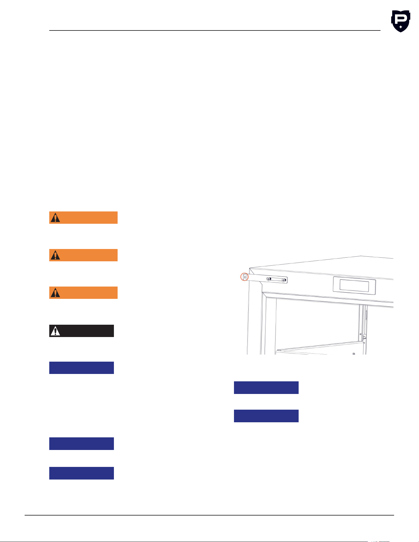
Anti Tip Installation
An anti-tip bracket is included with the unit and
must be installed after the unit is installed and
leveled. The anti-tip bracket must be attached to
the front of the unit.
To install the anti-tip bracket:
1. Remove plastic inserts from unused hinge
bracket holes.
2. Loosely attach the bracket to the front of
the unit using the supplied screws.
3. Slide the bracket until it contacts the adja-
cent under counter unit.
4. Secure the bracket to the adjacent unit
using appropriate fasteners (not supplied by
Perlick). NOTE: The type of fastener used to
attach the anti-tip bracket is dependent on
the material the adjacent undercounter unit.
5. Fully tighten the screws securing the bracket
to the front of the undercounter.
For free-standing units an anti-tip bracket is sup-
plied with the unit.
NOTICE
If installing on a concrete
oor, concrete fasteners are
required and not included with the anti-tip kit.
NOTICE
Some installation sites may
require modifications to
provide a secure surface for attaching the
brackets.
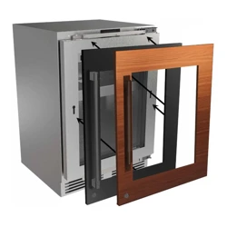
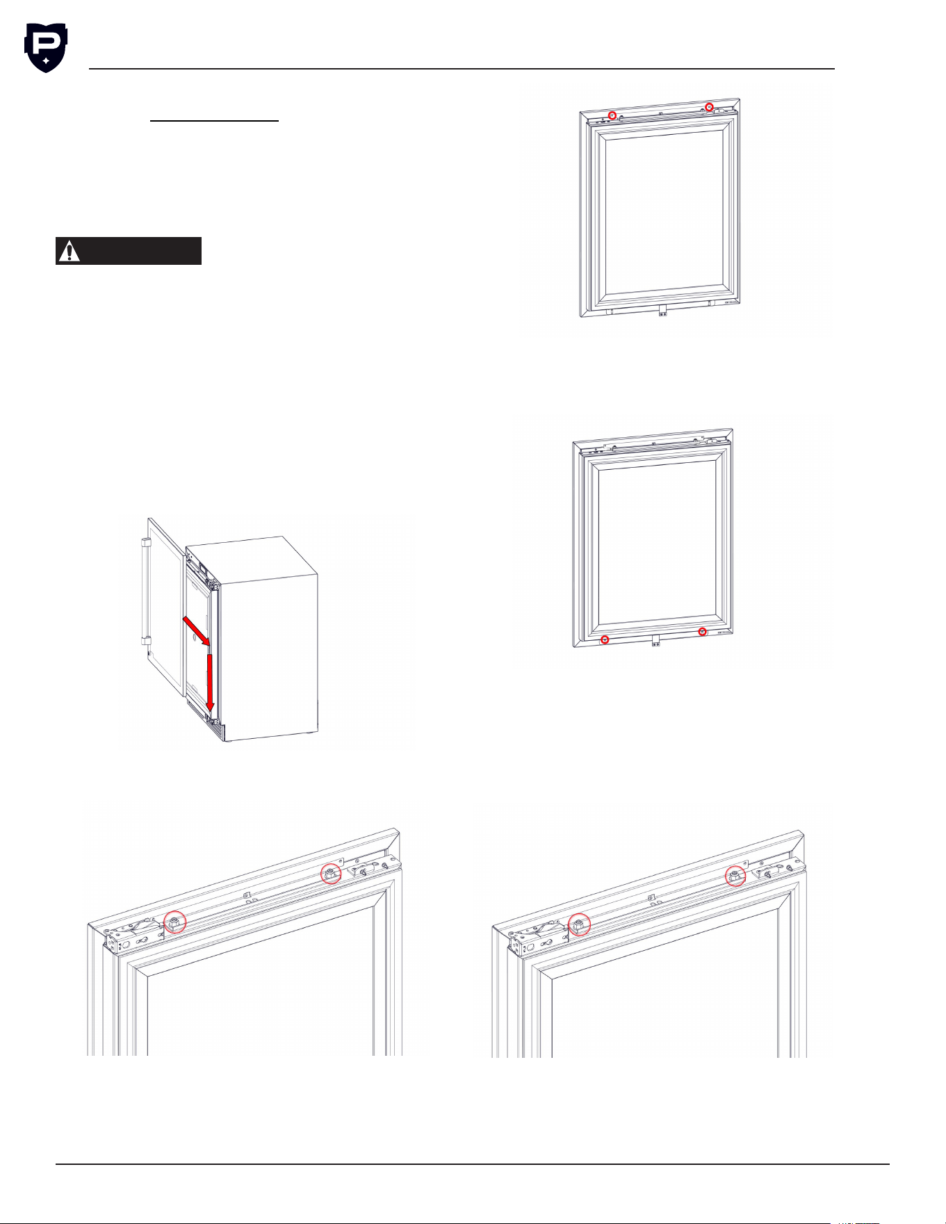
Overlay Installation and Door Orientation
Overlay Installation and Removal
Before beginning installation, check all compo-
nents for proper t and nish.
Wood Overlay
G5 User Installation & Operation Manual
Perlick is committed to continuous improvement. Therefore, we reserve the right to change specications without prior notice.
10
Build the overlay per the overlay template, can
be found on www.perlick.com. The shoulder bolt
must be attached to the wood overlay prior to
installation. Handle should be installed to the over-
lay prior to installing overlay to the door.
NOTE: When installing handle(s) in wood
overlay(s), use countersunk athead fasteners.
CAUTION
For best performance and
functionality, the overlay
panels should be no more than 3/4” thick. The
weight of the overlays should not exceed 20 lbs
for solid (-2) doors, 10 lbs for glass (-4) doors,
or 10 lbs for each drawer (-6) models.
1. Lift door overlay up against the door.
2.
Align shoulder bolt on the overlay to the top
of the slot in the door.
3.
Once the shoulder bolts are aligned, push the
overlay against the door. Then slide the door
down until the shoulder bolts slide to the bot
-
tom of the slots.
4.
Loosen both M8 nuts on top of the door, allowing
for easier adjustment when attaching overlay.
5.
Secure the top of the overlay to the door using
appropriate screws, if a Perlick branded over-
lay was used, then screws will be in the overlay
box. Ensure the screws are tighten fully.
6.
Attach the appropriate screws to the lower
holes of the overlay, DO NOT fully tighten the
screws yet.
7.
Level the overlay by adjusting standoffs in
the top bracket with a 4 mm allen key, can
use leveling leg tool. Adjust overlay depth so
overlay is tight to door and then tighten both
M8 nuts on top of door. Then tighten bottom
screws fully.
8.
Install the hinge cover bracket by sliding
cover over the upper tilt support bracket. The
cover bracket should slide over and behind
G5 Installation & Operation Manual
Perlick is committed to continuous improvement. Therefore, we reserve the right to change specications without prior notice.
11
Form No. Z3023
Rev. 02.23.26
the hinge. Align holes on the hinge and hinge
cover, then secure the cover bracket to the
hinge with the supplied #8 32x1/4 screw.
Finally secure the handle side of the hinge
cover with the supplied grey push rivet.
Uninstallation of the overlay is done using the
reverse order of the installation instructions.
NOTE: Once screws are removed from the tilt sup-
port brackets, slide the overlay up so the shoulder
bolts can clear the slot.
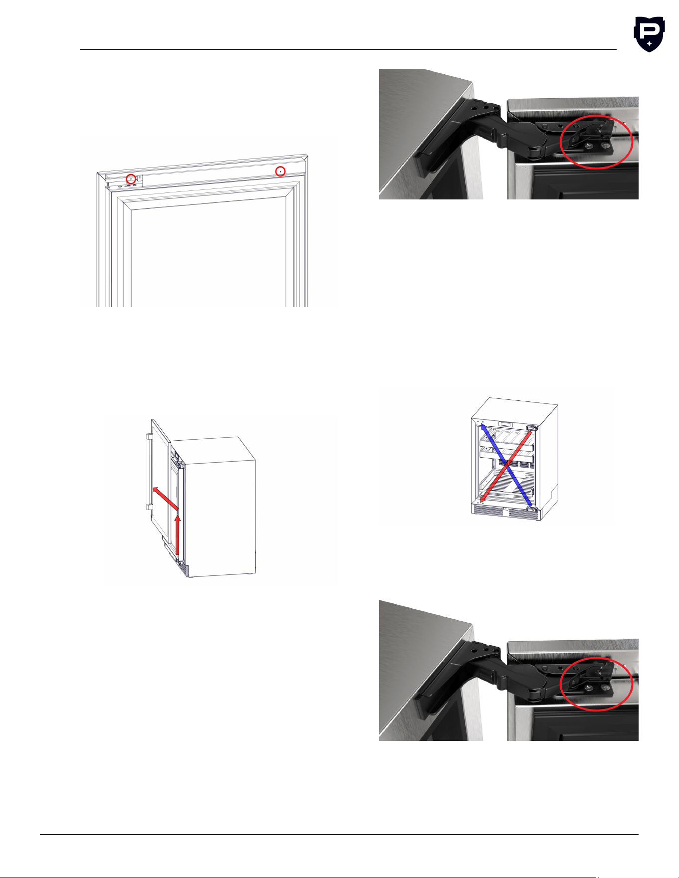
Hinge Direction
NOTE: An additional person is recommended to
hold and align the door.
1. Uninstall Overlay.
2. Close the cabinet door.
3. With the help of another person holding the
door, remove the bottom screws from the
bottom hinge to the door.
4. While holding the door, remove the top
screws from the top hinge.
5. Gently set door to the side to avoid damag-
ing the door.
6. Use a Phillips Screwdriver to remove the top
and bottom hinge from the unit.
7. Cross the hinge location when changing
hinge direction:
a. Reattach the top hinge to the bottom
corner.
b. Reattach the bottom hinge to the top
corner.
8. Lift door up against the unit. Secure the top
and bottom hinge brackets to the hinges
with screws.
G5 User Installation & Operation Manual
Perlick is committed to continuous improvement. Therefore, we reserve the right to change specications without prior notice.
12
INSTALLATION
Placing Unit
•
Prior to sliding the unit into location, plug in
the unit in.
• Slide the unit into position in the opening.
•
Push the unit into the opening until the bottom
front edge of the unit is ush with the sur-
rounding cabinetry.
Leveling Unit
Front and rear leveling legs can be adjusted from
the front once the unit is positioned. Remove the
grill to access leveling adjustment access holes.
Once the unit is in position, any height adjustment
can be made from the front. Using the hex driver
leveling tool, turn the hex driver clockwise to raise
the unit or counterclockwise to lower.
When the unit is properly leveled, door adjust-
ments are less likely to be necessary.
CAUTION
Level the unit to the oor, not
to the surrounding cabinetry.
This could affect the operation of the unit, such
as door closing.
WARNING
To reduce the possibility of
the unit tipping forward, the
front leveling legs must be in contact with the
oor.
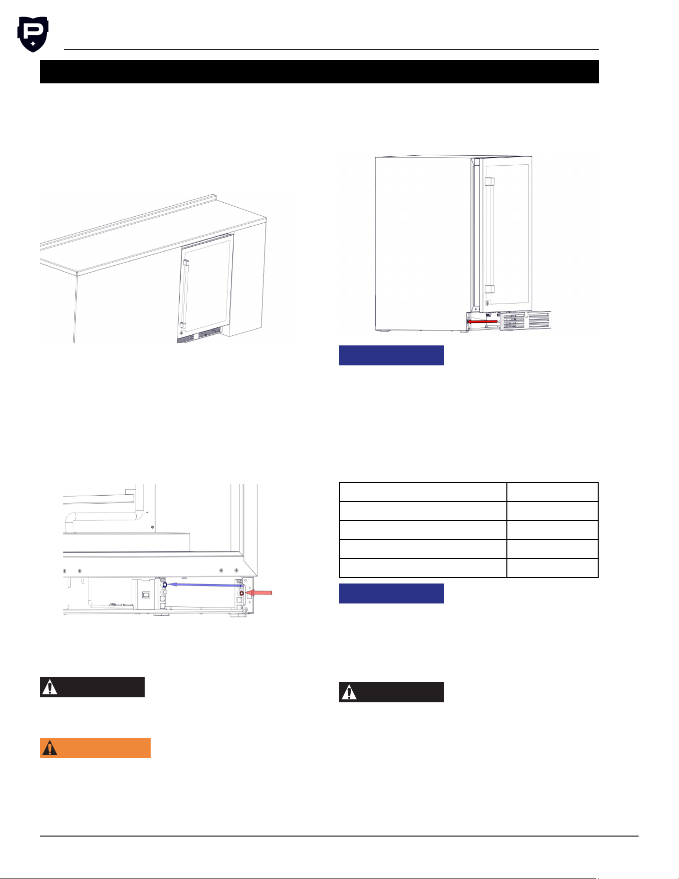
Front Grill Installation
Once the unit is secured in place, install the lou-
vered front grill. Secure the plate by snapping the
latch into the latch catch on the unit.
NOTICE
This unit requires proper ven-
tilation to operate correctly.
Do not block the louvers on the front grill or place
product directly in front of the evaporator fan
motor and evaporator cover louvers. Obstructed
ventilation can lead to poor performance and
compressor damage.
Shelving and Drawer
Shelf and Drawer Weight Limits
Style Load Limit
Wine Rack 70 lbs
Wire Form Shelf 70 lbs
Premium Stainless Steel 70 lbs
Drawer 75 lbs
NOTICE
If shelf or drawer is over-
loaded, it may cause
damage to the undercounter.
Shelving Installation and Adjustment
NOTE: Improper shelf/drawer installation may
not actuate slide mechanism.
CAUTION
Completely empty shelf or
drawer before removing.
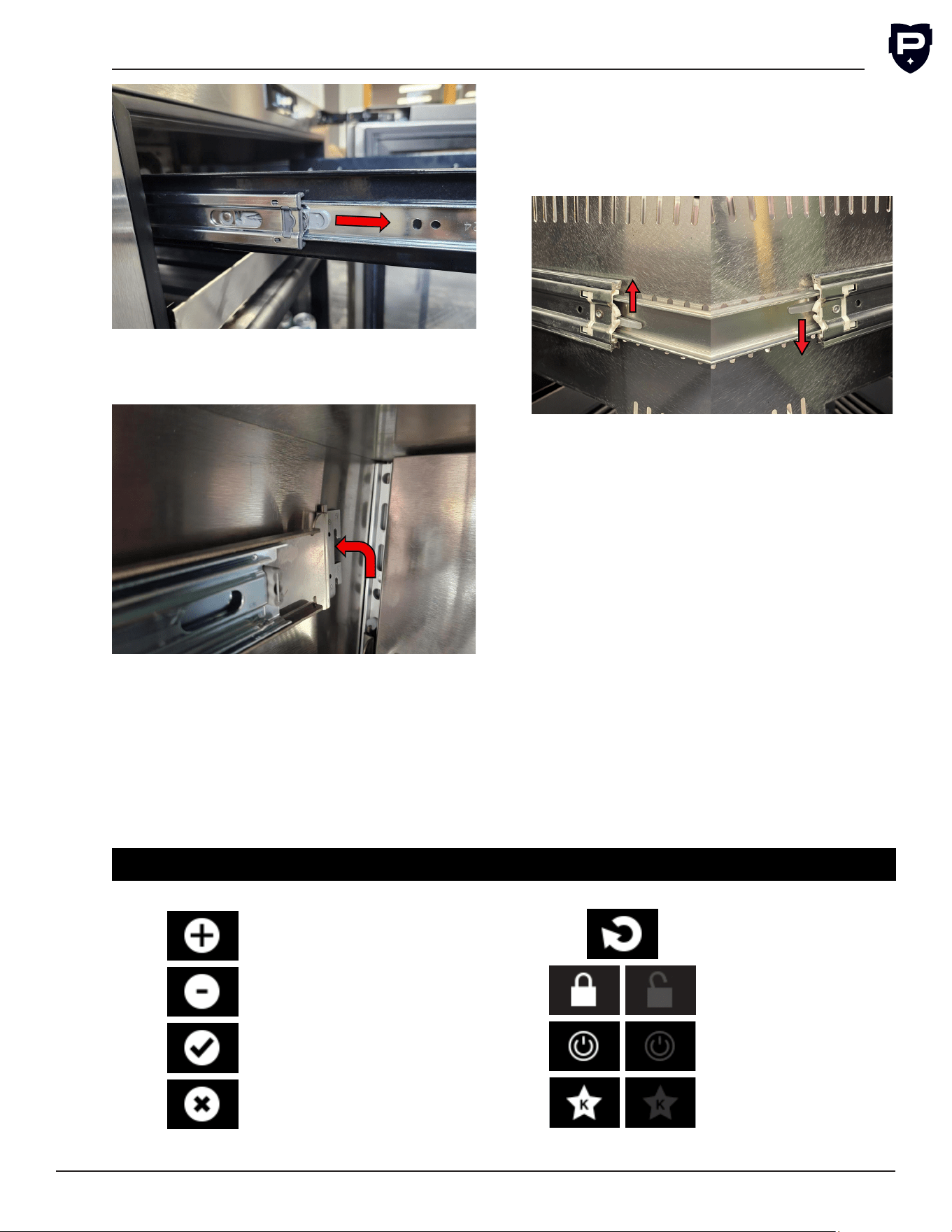
1.
Pull the shelf out to its furthest position. Locate
the tabs in the middle of both extenders. Pull
both tabs toward yourself, and pull shelf out.
G5 Installation & Operation Manual
Perlick is committed to continuous improvement. Therefore, we reserve the right to change specications without prior notice.
13
Form No. Z3023
Rev. 02.23.26
2. Remove each shelf bracket separately. Grasp
the middle of the bracket, lift the back up, then
pull forward to remove.
3. Position each shelf bracket separately. Grasp
the middle of the bracket, lift the back up, then
pull forward to remove.
4. Repeat steps 1 through 3 for other brackets.
5.
Push extenders completely into brackets. Align
the shelf/drawer grooves with the extenders
and slide completely into the unit.
Drawer Removal and Installation
Removal: Pull the drawer out to its furthest
position. Locate the tabs in the middle of both
extenders. Lift one tab up while pushing the oppo-
site tab down, and pull drawer out.
Installation: Push extenders completely into
brackets. Align the shelf/drawer grooves with the
extenders and slide completely into the unit.
Power Unit On
Once the unit is installed and level, verify the
master switch behind the front grill is in the on
position. Follow the instructions to set the date,
time, and temperature are in the Display Opera-
tion section.
Loading Product
Before storing any product, power unit on and
allow it to operate for 24 hours to allow tempera-
tures to stabilize. When loading product into the
unit, do not block internal louvers and fan guard
openings or performance will be decreased.
CONTROLS
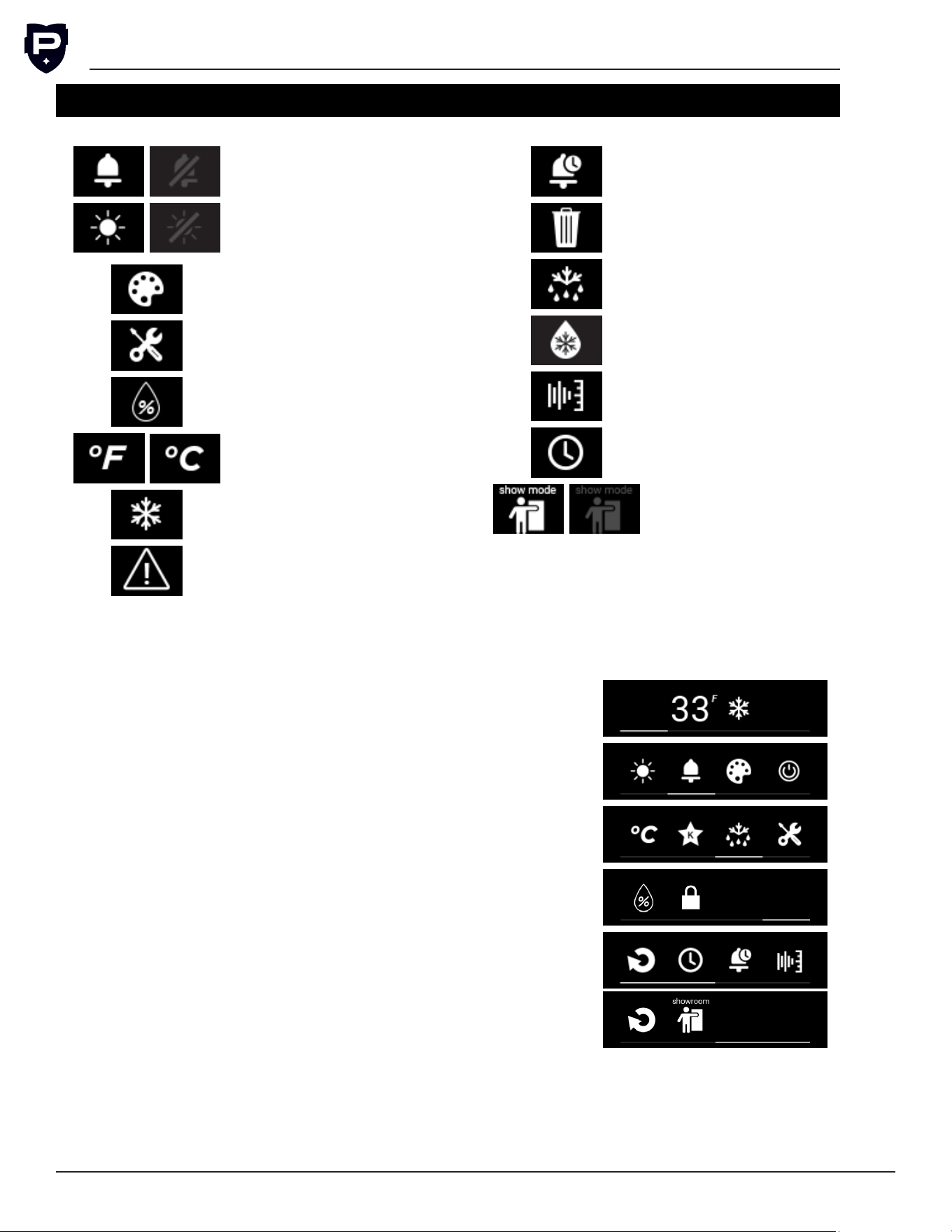
Display Icon Denitions and Operations
Increase Icon
Decrease Icon
Conrm Icon
Cancel Icon
Return Icon
Display Lock Icon
Power Icon
Sabbath Mode Icon
G5 User Installation & Operation Manual
Perlick is committed to continuous improvement. Therefore, we reserve the right to change specications without prior notice.
14
Button Sound Icon
Display Light Icon
Display Lighting
Color Icon
Service Menu Icon
Humidity Setpoint
Icon
Unit of Measure-
ment Icon
Quick Cool Icon
Active Alarm Icon
Alarm History Icon
Trash Icon
Evaporator Defrost
Icon
Cabinet
Defrost Icon
Diagnostics Icon
Time Date Icon
Showroom Display
Mode Icon
Main
Screen
Screen when door opens
Screen 2 Swipe right from main
Screen 3 Swipe right from screen 2
Screen 4 Swipe right from screen 3
Service Menu
Screens
Inside of selected menu
CONTROLS (CONT.)
Main Screen Icons
Disclaimer: Screen layouts may vary by model. Not all icons are
available on every unit. The screen layout shown may differ from
your actual product depending on the model purchased.
G5 Installation & Operation Manual
Perlick is committed to continuous improvement. Therefore, we reserve the right to change specications without prior notice.
15
Form No. Z3023
Rev. 02.23.26
Quick Cool
The Quick Cool feature accelerates cooling cycle
to bring cabinet to temperature, useful for after
loading products. Quick Cool automatically acti-
vates after initial power up. To activate Quick Cool,
select the icon. Quick Cool will terminate
automatically once the setpoint is achieved or
when the icon is selected a second time to dis-
able quick cool.
Display Lock
The Display Lock prevents settings from being
adjusted when activated. While the display is
locked, you can swipe through screens, acti-
vate quick cool, and silence alarms. To activate
the Display Lock, select the icon. Will be
prompted to conrm enabling the lock screen.
To unlock the screen, hold the Display Lock icon
for 3 seconds. A greyed out icon will indicate the
display lock is disabled.
Sabbath Mode
To activate Sabbath Mode, select the icon.
A greyed out icon indicates the unit is not in Sab-
bath Mode. There will be a prompt to conrm
activation of Sabbath Mode. Once Sabbath Mode
is activated, the display will not power on. To reac-
tivate, hold nger in the center of the display for
10 seconds to power on the display. Then tap on
the icon to deactivate Sabbath Mode.
Display Button Sound
The Display Button Sound Icon enables and dis-
ables the sound when interacting with the display.
To disable sound, swipe display menu until the
Icon is visible. Select the icon, the user
will be prompted to conrm disabling sound. A
greyed out display button sound icon indicates the
sound for display buttons is disabled. Alarms will
still sound when display button sound is disabled.
Select Unit of Measurement for Display
Temperature
To alternate between Fahrenheit and Celsius,
nd the unit of measurement (UoM) icon. Then
select the or icon until desired UoM
is selected.
Controller Operation
Master Switch
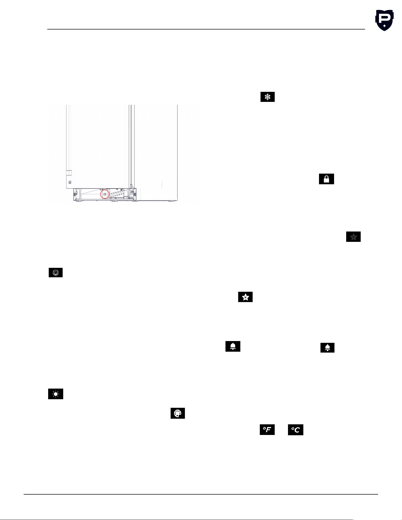
Under Counter units come equipped with a mas-
ter power switch located behind the louvered toe
kick. Remove the toe kick to turn power on or
off to the unit. Pull on each side of the toe kick
to remove.
Display
The display will turn on once the door is opened.
The display will remain on for 30 seconds after
the door is closed.
Standby/Power Off Mode
To place unit into standby mode, tap the power
icon on display and activate standby mode.
Then conrm that you want to turn off unit. In
standby mode, the unit still has power going to
all components. Do not attempt repairs/service
when in standby mode.
Interior Light
Under Counter units are equipped with an interior
light that will illuminate when the door/drawer is
opened. When unit is open the LED will turn to a
cool white color.
All glass door units have color LED ambiance light
for when door is closed. To enable or disable the
display light, swipe display till the display light icon,
A greyed out light icon will indicate interior
lights are disabled. LED light can be changed, to
access color menu swipe display to the icon
and select the icon. Once in the color adjustment
menu change to desired color. Desired color only
displays when the door is closed.
G5 User Installation & Operation Manual
Perlick is committed to continuous improvement. Therefore, we reserve the right to change specications without prior notice.
16
Defrost Operation
Manual Evaporator Defrost
The under counter unit is deigned to complete
automatic defrost on its own. The standard defrost
operation is intended to assist in maintaining and
servicing the unit. Swipe the display to the stan-
dard defrost icon, then select the icon. The
user will then be prompted to conrm the start of
a defrost. After completion of a standard defrost
the automatic defrost will resume.
NOTE: If the evaporator is too warm, or in quick
cool mode, then unit will not initiate the defrost.
Cabinet Defrost
The Cabinet Defrost completes an extended 6
hour defrost. The end user will initiate manual
defrost after every shift to prevent excessive ice
build up on the coils. Swipe the display until you
are at the manual defrost icon, then select the
icon. The user will then prompted to conrm
the start of the manual defrost. After completion
of a standard defrost the automatic defrost will
resume.
NOTE: Only available on the UCC24F and UCA24F
models
NOTICE
Cabinet Defrost is a 6 hour
defrost. Any ice or perish-
able items will melt or reach temperatures
upwards of 60F. Unit is not intended to store ice
and perishables outside of operational hours.
Return from Sub Menu
To return to the previous screen, select the
icon.
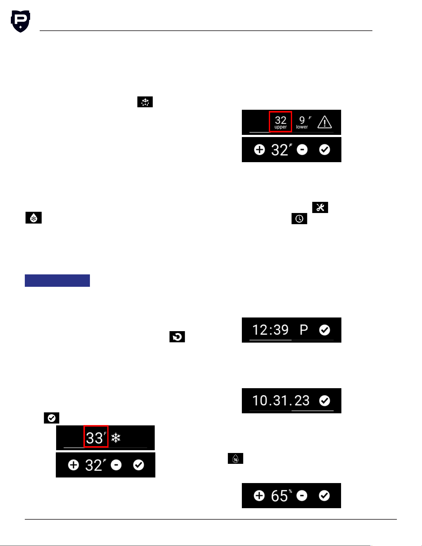
Changing Temperature
Single Zone
To change the temperature select the displayed
temperature on the screen. Then increase or
decrease the temperature as desired. Once tem-
perature is at desired set point click the conrm
icon, .
Dual Zone
On a dual zone unit there are two tempera-
tures displayed on the screen. To change the
temperature, select the temperature desired to
be changed. Then increase or decrease the tem-
perature to a new set point and select conrm
icon. To change the other set point, select the
display temperature and increase or decrease to a
new set point then select conrm icon. The upper
compartment temperature should be set at least
7°F higher than the lower compartment.
Time and Date
The date and time must be set for the unit upon
installation. All alarms will be time stamped based
on the set date and time. To set the date and time
select the Service Menu Icon . Then select
the Time and Date icon .
Time and Date will be preserved in the event of a
power loss. If an extended power loss occurred,
then verify the date and time are set correctly. To
change the date and time see below:
•
To change the time, hour then increase or
decrease as needed, select conrm icon once
at correct hour. Select the minutes, increase
or decrease to correct minute, select conrm.
Change between AM and PM by selecting the
“A” or “P” icon.
• To change the date, swipe right to access the
date menu. Select month and change to cor-
rect number and conrm. Repeat with the day
and year for the date, then select conrm icon
when whole date is correct.
Changing Humidity Percentage
The humidity percentage adjustment is only
available on wine units. To change the humid-
ity percentage, select the Humidity Percentage
icon . Increase or decrease the humidity to
preferred humidity percentage, then select the
conrm icon.
G5 Installation & Operation Manual
Perlick is committed to continuous improvement. Therefore, we reserve the right to change specications without prior notice.
17
Form No. Z3023
Rev. 02.23.26
Alarm History
To access the alarm history, select either the
Active Alarm icon, or select the Service Menu
Icon, then select the Alarm History icon. Once
inside the menu, swipe left and right to review
all the stored alarms, the alarms will be date and
time stamped. The alarm history stores up to ten
past alarms.
Or
•
To clear all alarm history, swipe to the Clear
History screen. Select the clear history icon. A
prompt will appear to conrm clearing history.
•
If no stored alarms exist, the “No Alarm History”
prompt will appear.
Show Room Mode
Showroom mode is intended for units that are
being used solely for display purposes. Showroom
mode has the user interface fully functional along
with the cabinet lights, however, no compressor,
evaporator fans or condenser fans will operate.
To enter show room mode, select the Service
Menu Icon and swipe right on screen. Then select
the show room icon. Once selected, the user will
be prompted to conrm enabling show room
mode. A greyed out icon indicates show room
mode is disabled.
Diagnostic Window
To access the diagnostic window, rst select the
service menu icon. Then select the Diagnostic
Window icon to open the display. The diagnostic
display window is useful whenever submitting a
service ticket for remote diagnostics.
Zone 1 Temp: For single zone is the cabinet tem-
perature. If dual zone than the lower or colder
section.
Zone 2 Temp: Only for dual zone units for the
upper warmer zone.
Evap. Temp: Temperature at the evaporator inlet.
Cond Temp: Temperature of the outlet of the
Condenser.
Humidity: On wine units, the humidity sensor is
installed and will display the humidity percentage.
Comp. Output: Gives the percentage of max
speed the variable speed compressor is running.
E. Fan Output: Percentage of max speed the fan
is running on the evaporator.
C. Fan Output: Percentage of max speed the fans
are running on the condenser.
Door SW 1: On single zone units, it identies if
the door is open (OPEN), or closed (CLOSED). For
drawer units, it displays data on the lower drawer.
Door SW 2: Only on drawer units, it identies if
the top drawer is open or closed.
Hot Gas Vlv.: Only on low temperature units or
dual zone units with a freezer section, this identi-
es if the hot gas solenoid valve is ON or OFF.
Air Dampers: Only for dual zone units, identies if
the damper is open or closed.
G5 User Installation & Operation Manual
Perlick is committed to continuous improvement. Therefore, we reserve the right to change specications without prior notice.
18
MAINTENANCE AND CARE
WARNING
Keep ventilation
openings, in the appliance enclosure or in the
built-in structure, clear of obstruction.
Cleaning the Condenser
WARNING
Do not use means to
accelerate the defrosting process or to clean the
evaporator and/or condenser coil other than
those recommended by the Perlick technical ser-
vice team.
CAUTION
Avoid damaging or crushing
the condenser ns or tubing.
Every 30 days is recommended to clean the con-
denser for optimal performance.
1. Remove front grill.
2.
Using a soft bristle brush or brush attachment
on a vacuum, remove all dust and debris from
the condenser.
3.
Verify no ns are damaged or bent. Use a
condenser comb to correct if any were bent.
DANGER
Flammable Refrig-
erant. Risk of re or explosion. Do not damage
refrigeration tubes.
CAUTION
Avoid damaging or crush-
ing the condenser ns or tubing.
WARNING
Do not use any
electrical appliances inside the food storage com-
partments of the appliance.
Seasonal Maintenance for Units Located
Outdoor
Winterizing
1. This process should occur when the daily low
temperatures are at or below environmental
operation temperatures, seen in the Environ-
ment Operations Table.
2.
Terminate power to the unit using one or more
of the following options:
a.
Turn the master switch located behind the
grill off.
b.
Unplug the power cord from electrical
receptacle.
c. Turn off the circuit breaker to the electrical
receptacle the cabinet is plugged into.
3. Remove all contents from the unit.
4. Remove the front grill.
5.
Clean the condenser by using a vacuum
cleaner to remove loose debris (leaves, dirt,
etc.) that may have accumulated inside the
grill.
6. Reinstall the front grill.
7.
Clean the interior and exterior of the unit using
stainless steel cleaner and polish.
NOTICE
Do not place a cover over
the unit. While not required, you may choose to
remove the unit from the outdoor location and
store indoors.
CAUTION
Operating the unit at tem-
peratures lower than those recommended will
void the warranty.
Spring Start-Up
This process should occur after the daily low tem-
peratures are above the environmental operation
temperatures, seen in the Environment Operations
Table.
1. Remove the front grill.
2.
Check the condensing unit to ensure it is clear
of loose debris, and clean as necessary with
a vacuum cleaner.
3. Reattach the front grill to the unit.
4.
Clean the interior and exterior of the unit using
stainless steel cleaner and polish.
5. Return power to the unit by:
a.
Plug the unit into the electrical receptacle
or turn on the circuit breaker.
b.
Turn on the master switch located behind
the grill. The controller display will then turn
on.
6.
The cooling process will begin to bring the
unit to the set point temperature. It’s rec-
ommended you run the unit for 24 hours to
stabilize the operating temperature before
using.
G5 Installation & Operation Manual
Perlick is committed to continuous improvement. Therefore, we reserve the right to change specications without prior notice.
19
Form No. Z3023
Rev. 02.23.26
DANGER
Never attempt to repair
or perform maintenance on the unit until the
main electrical power to the unit has been
disconnected!
Led Replacement
If an LED replacement is required, call your Perlick
Factory Authorized Service Center. For the loca-
tion of the Service Center in your area, contact
your selling dealer, inquire via the web at www.
perlick.com, E-mail us at warrantyserv@perlick.
com, or call 844-411-8050.
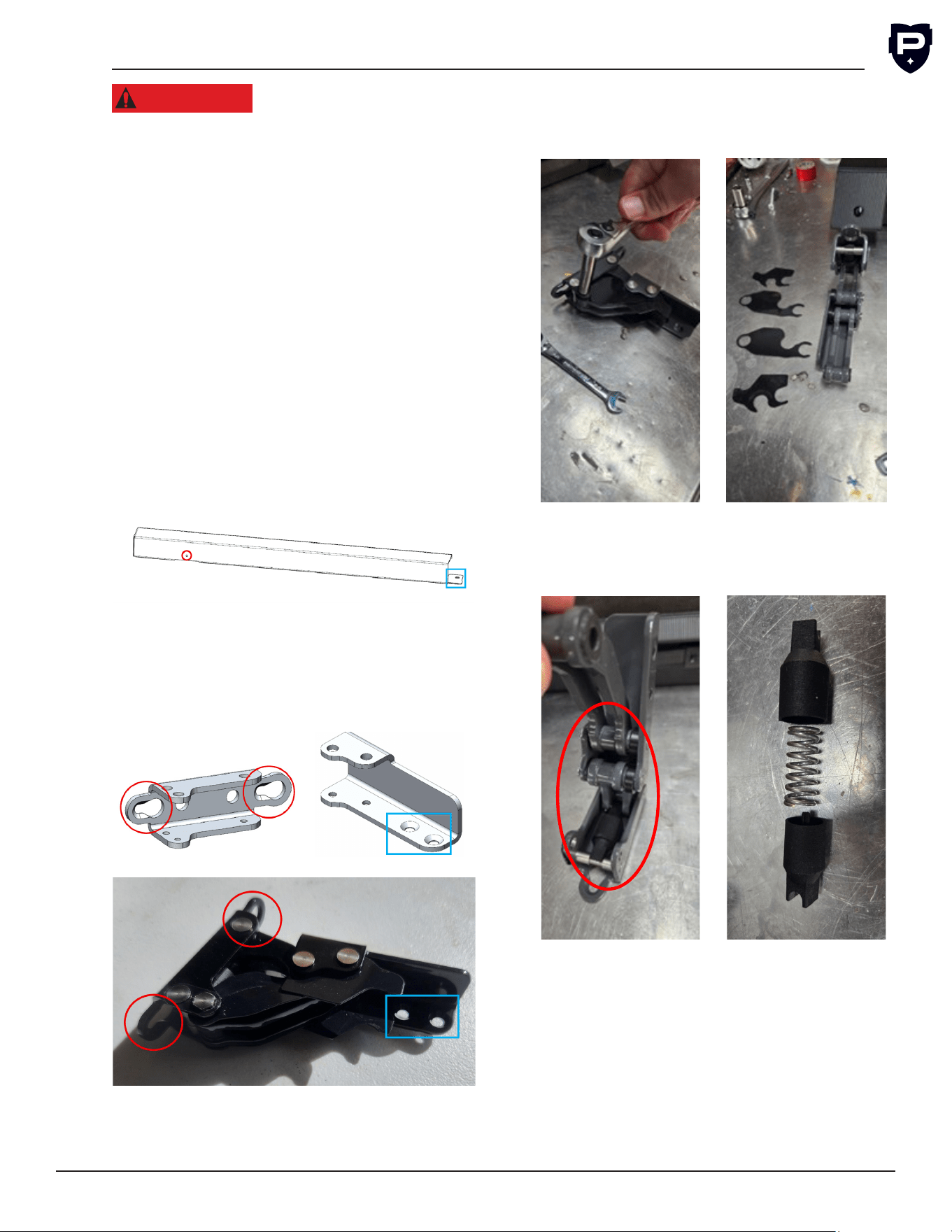
Commercial Hinge Removal and Cleaning (UC
Models)
1.
Using a at blade screwdriver remove the
press rivet, red circle. Using a Phillips Head
screwdriver remove screw from bracket to
door, blue square.
2.
Level the overlay by adjusting standoffs in
the top bracket with a 4 mm allen key, can
use leveling leg tool. Adjust overlay depth so
overlay is tight to door and then tighten both
M8 nuts on top of door. Then tighten bottom
screws fully.
3. Use a 5/16 socket or wrench to disassemble
the hinge and splash guard as shown.
4. Remove the spring cover from the hinge and
disassemble as shown.
5. Use a damp rag and clean hinge parts under
running water for three minutes.
6. To Re-install complete the steps in reverse
G5 User Installation & Operation Manual
Perlick is committed to continuous improvement. Therefore, we reserve the right to change specications without prior notice.
20
Replace Finger Guards
1.
Use a 5/16 socket or wrench to remove the
hex pin and move the locking tab.
2. Remove the two short nger guards from the
hinge.
3.
Unclip the long nger guards from the bush-
ing and remove from the pin.
Install Finger Guards
1.
Install the two short nger guards onto the
pins. NOTE: Make sure the leg is below the
bushing ange so it is against the arm. Then
rotate into place. Follow instructions for both
short guards.
2.
Slide the long guard under the short guard on
the pin and clip the other end of guard over
the bushing. Repeat for the bottom long arm.
3.
With the hinge closed, align the arm and hinge
and insert the pin. Tighten with a 5/16 socket
or wrench.
4. Rotate locking tab and lock over the hex.
5.
Test hinge several times to ensure it moves
freely.

G5 Installation & Operation Manual
Perlick is committed to continuous improvement. Therefore, we reserve the right to change specications without prior notice.
21
Stainless Steel Care & Cleaning
General
Stainless steel is a “passive” metal because it
contains other metals like chromium, nickel and
manganese that stabilize the atoms. Chromium
provides an invisible passive lm that covers the
steel surface, acting as a shield against corro-
sion. If the lm is intact and not contaminated, the
metal is passive and stainless. If the passive lm
of stainless steel has been broken, equipment can
start to corrode and rust.
The following materials or processes can break
down stainless steel’s passive layers and allow
corrosion to occur:
Mechanical abrasion refers to items that will
scratch a steel surface. Steel pads, wire brushes
and scrapers are prime examples.
Water comes out of the faucet in varying degrees
of hardness. Hard water may leave spots. When
allowed to sit, these deposits will break down the
passive chromium layer and rust stainless steel.
Other deposits from food preparation must be
promptly removed with an appropriate cleaning
agent.
Chlorides are found nearly everywhere. They
are in water, food, and table salt. Household and
industrial cleaners are the worst offenders.
Preventing Stainless Steel Rust
Use non-abrasive tools to clean stainless steel
products. Soft cloths and plastic scouring pads
will not harm the steel’s passive layer.
Clean with polish lines. Some stainless steels have
visible polishing lines or “grain”. When visible lines
are present, always scrub in a motion parallel to
the lines. When the grain cannot be seen, polish in
a consistent straight pattern and not in a circular
motion.
Use alkaline, alkaline chlorinated or non-chloride
containing cleaners. While many traditional
cleaners are loaded with chlorides, the industry
is providing more options of non-chloride clean-
ers to consumers. If you are not sure of chloride
content in the cleaner being used, contact your
cleaner supplier. If your cleaner contains chlorides,
ask your supplier for an alternative. Avoid clean-
ers containing quaternary salt; it also can attack
stainless steel and cause pitting and rusting.
Keep food equipment clean. Use alkaline, alka-
line chlorinated or non-chloride cleaners at
recommended strength. Clean frequently to avoid
build-up of hard, stubborn stains. The single most
likely cause of damage is chlorides in the water.
Remember, adding heat to cleaners that contain
chlorides dramatically increases their effect on
stainless steel.
If chlorinated cleaners are used, immediately
rinse and wipe equipment and supplies dry. The
sooner you wipe standing water, especially when
it contains cleaning agents, the better. After wip-
ing equipment down, allow it to air dry. Oxygen
helps maintain the stainless steel passive lm.
Cleaning the Cabinet Interior/Exterior
NOTICE
NEVER use hydrochloric acid
(muriatic acid) on stainless steel. Do not use abra-
sive cleansers or cloths on any interior or exterior
surfaces or removable parts.
Glass panels may be cleaned using any standard
glass cleaner available on the market.
To clean interior and exterior non-metallic surfaces
and removable parts, wash with mild solution of
soap and lukewarm water with a little baking soda.
Rinse and dry thoroughly. Avoid getting water on
the lights, controllers, fan motors and unnished
wood wine rack faces.
G5 User Installation & Operation Manual
Perlick is committed to continuous improvement. Therefore, we reserve the right to change specications without prior notice.
22
Job Cleaning Agent Comments
Routine Cleaning Soap, ammonia, detergent Apply with sponge or soft cloth.
Fingerprints and smears Areal 20, Lac-O-Nu, Lumin
Wash, O-Cedar Cream Polish
Provides barrier lm to minimize ngerprints.
Can be used on all nishes. Rub the surface with
a cloth as directed on the package.
Stubborn stains and
discolorations
AllChem Concentrated
Cleaner, Samae, Twinkle,
Cameo Copper Cleaners,
Grade FFF Italian Pumice
Whiting, Steel Bright, Lumin
Cleaner, Zud Restoro, Sta-
Clean, Highlite Cooper’s
Stainless Steel Cleaner
or Revere Stainless Steel
Cleaner
Apply with a damp sponge or cloth, then rinse
with clear water and wipe dry.
Old Dutch, Lighthouse
Sunbrite, Wyandotte Bab-O,
Gold Dust, Sapollo, Bon Ami
or Comet
For these household cleaners, rub with a damp
cloth. They may contain chlorine bleaches so
rinse thoroughly after use and wipe dry.
Liquid NuSteel or Dubois
Temp
For these products, rub the surface with a dry
cloth using only a small amount of cleanser.
Rinse with water and dry.
Heat tint or heavy
discoloration
Penny-Brite, Copper Brite,
Paste Nu-Steel, Dubois Temp
or Tarnite
Rub onto surface with a dry cloth.
Tenacious deposits, rust,
discoloration, industrial
atmospheric stains
Bar Keepers Friend, Revere
Stainless Steel
When using these cleaners, apply with a damp
sponge or cloth, rinse thoroughly and wipe dry.
Oakite No. 33 Dilac, Texo NY,
Flash-KlenzCaddy Cleaner,
Turco Scale 4368 or Permag
57
Swab and soak with a clean cloth. Let stand for
15 minutes or more according to directions on
package, then rinse and wipe dry.
Rust discoloration
or corrosion caused
by cleaning agents
containing hydrochloric
(muriatic) acid or
chlorine bleach
3M Scotch Pad, type A,
grade “ne”
Clean off the surface soil using cleaning meth-
ods above. Then rub discolored or corroded
areas lightly with a dry pad.
Use of property names is intended only to indicate a type of cleaner and does not constitute an endorse-
ment. Omission of any proprietary cleaner does not imply its inadequacy. All products should be used in
strict accordance with instructions on the package.
NOTE: Do NOT use steel wool or scouring pads to clean stainless steel.
For Product Information:
• Contact your selling dealer.
• Inquire via the web at perlick.com
• Call 844-411-8050 for factory assistance on planning installation or product information
• Write to Perlick Corporation, Customer Service Department,
8300 West Good Hope Road, Milwaukee, WI 53223
G5 Installation & Operation Manual
Perlick is committed to continuous improvement. Therefore, we reserve the right to change specications without prior notice.
23
Form No. Z3023
Rev. 02.23.26
For Product Service:
•
Check the model and serial number of your
unit located on the label attached to the inside
top of the cabinet.
• Inquire via the web at www.perlick.com
• Call 844-411-8050 for factory assistance
• Email us at warrantyserv@perlick.com
For Replacement Parts and Accessories:
•
Use only genuine Perlick replacement parts
and accessories. Genuine Perlick parts and
accessories are designed to work correctly
with Perlick products and offer superior service
life. The use of non-Perlick parts can damage
the unit and may void the warranty.
•
Check the model and serial number of your
unit located on the label attached to the inside
top of the cabinet. Call your Perlick Factory
Authorized Service Center.
• Inquire via the web at www.perlick.com
• Call 844-411-8050 for factory assistance
• Email us at warrantyserv@perlick.com
Trouble Shooting
If the unit appears to be malfunctioning, read
through the OPERATION section of this manual
rst. If the problem persists, check this trouble-
shooting section to see if you can refer to the
cause and remedy of the problem and resolve it
without a service call.
DANGER
Never attempt to repair
or perform maintenance on the unit until the
main electrical power to the unit has been
disconnected!
Alarms and Faults
Error Code Fault Resolution
UIX Display Communication Fault Reset power to unit, either using rocker switch or break-
er. If fault continues:
Call Service: +1 844-411-8050
MEM MC Memory Fault
TCX Extra High Condenser Tem-
perature
Call Service: +1 844-411-8050
TEX Evaporator temperature ex-
ceeds safe operation zone
Call Service: +1 844-411-8050
TEY Extra Low Evaporator Tempera-
ture
Run a manual defrost for unit. If the alarm repeats within
a week:Call Service: +1 844-411-8050
DO2 Door Opening Long Period Close the door and activate a defrost cycle.
P1F Zone 1 Probe Fault Acknowledge code. If the alarm repeats within a week:
Call Service: +1 844-411-8050
P2F Zone 2 Probe Fault
PEF Evaporator Probe Fault
TCL Low Condenser Temperature Verify ambient temperature was above set point of the
unit, if below set point see winterizing unit instructions.
Condenser fans could remain running, power cycle unit
with rocker switch. If the alarm repeats within a week:
Call Service: +1 844-411-8050
PWR Power Outage Verify that all temperature sensitive product did not spoil
during power loss.Verify the correct date and time are
entered in the date and time menu .
G5 User Installation & Operation Manual
Perlick is committed to continuous improvement. Therefore, we reserve the right to change specications without prior notice.
24
T1H High Zone 1 Temperature • Verify door and gasket are fully sealing to fridge
front.
• Check condenser coils for buildup and clean con-
denser coils per maintenance instructions.
• Ensure front grill is not blocked or obstructed.
• If surrounding ambient temperature has recently
changed dramatically, the compartment may be
affected.
• If warm product was recently placed in the cabi-
net. Wait 24 hours for the product to chill and then
recheck the temperature.
If the alarm repeats within a week:
Call Service: +1 844-411-8050
T2H High Zone 2 Temperature
T1L Low Zone 1 Temperature Verify door and gasket are fully sealing to fridge front.
If surrounding ambient temperature has recently
changed dramatically, the compartment may be af-
fected.
If the alarm repeats within a week:
Call Service: +1 844-411-8050
T2L Low Zone 2 Temperature
TCH High Condenser Temperature Clean condenser coils per maintenance instructions. If
the alarm repeats within a week:
Call Service: +1 844-411-8050
TEL Low Evaporator Temperature Activate a defrost cycle. Verify the door shuts prop-
erly, gasket seals fully, and product is not blocking the
evaporator fan or louvered inlets. If the alarm repeats
within a week :Call Service: +1 844-411-8050
DO1 Door Opening Short Period Close the door.
PCF Condenser Temperature Fault Acknowledge code. If the alarm repeats within a
week:Call Service: +1 844-411-8050
PHF Humidity Sensor Fault
FCF Condenser Fan Fault Call Service: +1 844-411-8050
FEF Evaporator Fan Fault
F2F Zone 2 Fan Fault
SERVICE AND REPAIRS
Service
WARNING
All service work and repairs
should be performed by Perlick-authorized ser-
vice personnel. All component parts shall be
replaced with like components. Incorrect parts or
improper service may result in injury, damage to
property, or re. All warranty service will need to
be performed by Perlick authorized service agent
using only OEM parts.
For Product Service:
• Check the model and serial number of your
unit located on the label attached to the
inside top of the cabinet.
• Inquire via the web at www.perlick.com
• Call 844-411-8050 for factory assistance
• Email us at warrantyserv@perlick.com
Repairs
WARNING
Ensure that the area is in
the open or that it is adequately ventilated before
breaking into the system or conducting any hot
work. Proper ventilation must be present dur-
ing the period that the work is carried out. The
ventilation should safely disperse any released
refrigerant and preferably expel it externally into
the atmosphere.

G5 Installation & Operation Manual
Perlick is committed to continuous improvement. Therefore, we reserve the right to change specications without prior notice.
25
Form No. Z3023
Rev. 02.23.26
WARNING
When performing any ser-
vice or repair work, all wiring and cabling should
be inspected to ensure that it will not be subject
to wear, corrosion, excessive pressure, vibration,
sharp edges, or any other adverse environmental
effects. This inspection shall also take into account
the effects of aging or continual vibration from
sources such as compressors or fans.
Leak Detection of Flammable Refrigerants
DANGER
Under no circumstances shall
a potential sources of ignition be used in search-
ing for or detection of refrigerant leaks. A halide
torch (or any other detector using a naked ame)
shall not be used.
The following leak detection methods are permis-
sible with ammable refrigerants:
•
Electronic leak detectors that have adequate
sensitivity and are calibrated. Ensure the elec-
tronic leak detector is suitable for being used
with ammable refrigerants and are set at the
appropriate LFL for R600a.
• Soap and bubble method.
If a leak is suspected, all naked ames shall be
removed and/or extinguished.
If a leakage of refrigerant is found which requires
brazing, all refrigerant shall be recovered from the
system, or isolated (by means of shut off valves)
in a part of the system remote from the leak.
Refrigerant Removal & System Evacuation
DANGER
When breaking into the refrig-
erant circuit to make repairs it is important that
best repair practices are always followed due to
the ammability of the refrigerant. The following
procedure shall be adhered to:
a.
Safely remove refrigerant following local
and national regulations
b. Purge the circuit with inert gas
c. Evacuate
d. Purge with inert gas
e. Open the circuit by cutting or brazing
The refrigerant charge shall be recovered into the
correct recovery cylinders if venting is not allowed
by local and national codes. The system shall be
purged with oxygen-free nitrogen to render the
appliance safe for ammable refrigerants. This
process might need to be repeated several times.
Compressed air or oxygen shall not be used for
purging refrigerant systems.
Refrigerant purging is achieved by breaking the
vacuum in the system with oxygen-free nitrogen
and continuing to ll until the working pressure is
achieved. The gas is then vented into the atmo-
sphere, and nally pulling down to a vacuum. This
process shall be repeated until no refrigerant is
within the system. When the nal oxygen-free
nitrogen charge is used, the system shall be
vented down to atmospheric pressure to enable
work to take place.
Ensure that the outlet for the vacuum pump is not
close to any potential ignition sources and that
ventilation is available.
Recovery Of Flammable Refrigerants
DANGER
When removing refrigerant
from a system, either for servicing or decom-
missioning, it is recommended good practice that
all refrigerants are removed safely.
When transferring refrigerant into cylinders,
ensure that only appropriate refrigerant recovery
cylinders are employed. Ensure that the correct
number of cylinders for holding the total system
charge is available. All cylinders to be used are
designated for the recovered refrigerant and
labelled for that refrigerant (i.e., special cylinders
for the recovery of refrigerant). Cylinders shall be
complete with pressure-relief valve and associ-
ated shut-off valves in good working order. Empty
recovery cylinders are evacuated and, if possible,
cooled before recovery occurs.
The recovery equipment shall be in good working
order with a set of instructions concerning the
equipment that is at hand and shall be suitable for
the recovery of all appropriate refrigerants includ-
ing, when applicable, Flammable Refrigerants.
G5 User Installation & Operation Manual
Perlick is committed to continuous improvement. Therefore, we reserve the right to change specications without prior notice.
26
e.
Label the system when charging is com-
plete (if not already).
f.
Extreme care shall be taken not to overll
the refrigerating system.
Prior to recharging the system, it shall be pres-
sure-tested with the appropriate purging gas.
The system shall be leak-tested on completion
of charging but prior to commissioning. A follow
up leak test shall be carried out prior to leaving
the site.
DECOMMISSIONING AND DISPOSAL
R-600 Class A3 Flammable Refrigerant
Used
DANGER
Risk of Fire or Explosion. Flammable Refrigerant
Used.
It is important to decommission and dispose of
this product in accordance with all federal, state,
and local regulations.
DANGER
Risk of child entrapment.
Before you throw away your old refrigerator or
freezer:
• Take off the doors.
•
Leave the shelves in place so that children may
not easily climb inside.
WARNING
Do not use
mechanical devices or other means to acceler-
ate the defrosting process, other than those
recommended by the manufacturer.
WARNING
Do not use means to
accelerate the defrosting process or to clean
the evaporator and/or condenser coil other than
those recommended by the Perlick technical
service team. If the appliance is going to be
decommissioned and stored, it shall be stored in
a room without continuously operating ignitions
sources such as open ames, gas appliances, or
electric heaters. Do not pierce or burn. Be aware
Flammable Refrigerant Charging Procedure
DANGER
In addition to conventional
charging procedures, the following requirements
shall be followed:
a.
Ensure that contamination of different
refrigerants does not occur when using
charging equipment.
b. Hoses or lines shall be as short as possible
to minimize the amount of refrigerant con-
tained in them.
c.
Cylinders shall be kept in an appropriate
position according to the instructions.
d.
Ensure that the refrigerating system is
earthed prior to charging the system with
refrigerant.
that refrigerants may not contain an odor.
•
Be sure to follow all the Important Safety Infor-
mation located at the beginning of this manual
as well as the Important Safety Information
located in the Service & Repairs section of
this manual prior to any decommissioning &
disposal work.
Decommissioning & Disposal – (End of Life)
•
Servicing shall be done by trained service per-
sonnel with certied competence in handling
ammable refrigerants to minimize the risk of
possible ignition due to improper service.
•
Follow handling instructions carefully in compli-
ance with national regulations.
• Do not puncture refrigerant tubing. Risk of re
or explosion due to puncture of refrigerant tub-
ing; follow handling instructions carefully.
•
The appliance contains a ammable refrigerant
and must be disposed of in accordance with
applicable national, state, and local codes and
regulations. Refrigerant must be recovered and
safely disposed of by properly trained service
personnel.
•
Prior to disposal of this product the refrigerant
must be completely removed.
•
When removing refrigerant from a system, it
is recommended and good practice that all
refrigerants are removed safely.
• Before carrying out this procedure, it is essen-
tial that the technician is completely familiar
with the equipment and all its detail. It is rec-
ommended good practice that all refrigerants

G5 Installation & Operation Manual
Perlick is committed to continuous improvement. Therefore, we reserve the right to change specications without prior notice.
27
Form No. Z3023
Rev. 02.23.26
are recovered safely. Prior to the task being
carried out, an oil and refrigerant sample shall
be taken in case analysis is required prior to
re-use of recovered refrigerant. It is essential
that electrical power is available before the task
commences.
•
The recovery equipment shall be in good work-
ing order with a set of instructions concerning
the equipment that is at hand and shall be suit-
able for the recovery of ammable refrigerants.
In addition, a set of calibrated weighing scales
shall be available and in good working order.
Hoses shall be complete with leak-free discon-
nect couplings and in good operating condition.
Before using the recovery machine, check that
it is in satisfactory working order, has been
properly maintained and that any associated
electrical components are sealed to prevent
ignition in the event of a refrigerant release.
Consult manufacturer if in doubt.
• Before refrigerant recovery, ensure that:
○
Mechanical handling equipment is available,
if required, for handling refrigerant cylinders.
○
All personal protective equipment is avail-
able and being used correctly.
○ Isolate the system electrically.
○
The recovery process is always supervised
by a competent person.
○
Recovery equipment and cylinders conform
to the appropriate standards.
•
When transferring refrigerant into cylinders,
ensure that only appropriate refrigerant recov-
ery cylinders are employed. Ensure that the
cylinder is sized correctly to hold the entire
refrigerant charge. All cylinders to be used are
designated for the recovered refrigerant and
labeled for that refrigerant (i.e., special cylin-
ders for the recovery of refrigerant). Cylinders
shall be complete with pressure-relief valve
and associated shut-off valves in good working
order. Empty recovery cylinders are evacuated
and, if possible, cooled before recovery occurs.
•
Even after refrigerant recovery, some residual
refrigerant can be left entrained with the refrig-
erant oil. Cut out the compressor and drain
and dispose of the compressor oil. Compressor
oils are to be removed, ensure that they have
been evacuated to an acceptable level to make
certain that ammable refrigerant does not
remain within the lubricant. Dispose of com-
pressor and compressor oil in compliance with
national, state, and local codes and regulations.
•
The recovered refrigerant shall be returned to
the refrigerant supplier in the correct recovery
cylinder, and the relevant waste transfer note
arranged. Do not mix refrigerants in recovery
units and especially not in cylinders.
•
All doors and drawers of the unit being dis-
posed must be completely removed from the
unit to avoid the risk of child entrapment. Leave
shelving in place so children cannot easily
climb inside.
•
Disposal of this product shall be in compliance
with all federal, state, and local regulations.
Labeling
Equipment shall be labeled stating that it has
been decommissioned and emptied of refrigerant.
The label shall be dated and signed. For appli-
ances containing ammable refrigerant, ensure
that there are labels on the equipment stating the
equipment contains ammable refrigerant.

Form No. Z3023
Rev. 02.23.26