Page 1 of 8
RCB09A
Touch Screen Remote Control for Millivolt Valve
Installation and Operating Instructions
IF YOU CANNOT READ OR UNDERSTAND THESE INSTALLATION INSTRUCTIONS. DO NOT ATTEMPT TO INSTALL OR OPERATE
This wireless thermostatic on/off/ remote control transmitter is designed to be used with millivolt valve gas
appliances. It can be operated thermostatically or manually from the transmitter or turned on and off manually
from the receiver.
CONTENTS OF KIT
Description Quantity
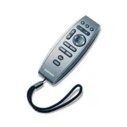
Transmitter 1
RCB09A Touch Key Remote Control Transmitter 1
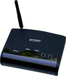
Receiver 1
White Color Slide Button 1
White Color Wall Cover Plate 1
Wiring Assembly – 18” Inches 1
Installation Instructions 1
#6 3/4 Screws (for Wall Cover Plate and Remote control) 4
#6 3/4 Screws (for fireplace system control covers)
Plastic wall anchors (for installing transmitter)
2
2
NOTE: Due to the sensitive temperature monitoring components in the transmitter, it is necessary to allow the
transmitter to stabilize to room temperature before accurate room temperature are displayed, If the transmitter is
activated from a severe cold condition allow 15 minutes for accurate temperature reading to appear on the LCD.
The user hand don’t closed to temperature sensor location to avoid it influence the detect temperature of sensor
Touch anyplace on the screen and the screens blue back light will light up and stay on Four seconds.
WARNING
Important Safety Information
• Read this manual thoroughly prior to installing, programming or operating any remote control.
• This remote control system is designed for use with a millivolt or 24V gas valve system. Do not use
this remote control system on applications with voltages above 24 Volts AC/DC and 1 amp current.
• This remote control system requires four (4) “AAA” and four (4) “AA” alkaline batteries to power the
transmitter and receiver.
•
Turn appliance OFF (at the appliance or remote receiver) if you are away from your house for a
long period of time.
FEATURES/SPECIFICATIONS
Easy Operate Manual Adjustment and Thermostat Control
Battery Powered Transmitter and Receiver
Low battery Indication
Select Between °C and °F display
Child Proof Lock-out
16 Security Codes
Quick Disconnect Wiring Assembly
Touch Key Function
Note On initial startup if a LOW battery icon appears on the screen, check the position of the batteries.
WARNIN
G
Turn appliance OFF and allow to cool before installing or servicing. DO NOT connect
110-120 VAC wiring to the millivolt gas control valve. The remote operator must be installed
exactly as outlined in these instructions. Read all instructions completely before attempting
installation. Follow instructions carefully during installation. Any modification of
components will void the warranty and may cause a fire hazard.
Page 2 of 8
RCB09A Transmitter:
Installing Batteries:
The remote transmitter uses four (4) “AAA” batteries. To install batteries:
1. Press down the battery door and remove the battery door.
2. Install uses four (4) “AAA” batteries as indicated on transmitter.
3. Close the battery door by snapping in place.
4. The batteries should be replaced when the low battery indicator display in LCD.
5. When (4) “AAA” batteries are installed, the transmitter will initialize for 1 seconds and then is ready
for use.
LEARNING TRANSMITTER TO RECEIVER (Manufactory have done the default setting learning,User
can skip learning if not change the Security Codes)
1. The transmitter privacy (DIP) Switches are preset at the factory. Setting the 4 bits DIP Switches on
transmitter to select a security code.
2. Put the receiver slide switch to “REMOTE” location. Using a small screwdriver or end of a paper clip
gently press and Hold the LEARN button on the receiver to accept the transmitter security code upon initial use,
When you release the LEARN button the receiver will emit an audible “beep
3. After the receiver emits the beep. Press the “Mode/SET “button or press “On Thermo OFF” button of touch
screen, The remote will transmitter signal and receiver will emit several beeps indicating that the transmitter’s
code has been accepted into the receiver.
4. If you are unsuccessful in matching the security code on the first attempt repeat step 1-3
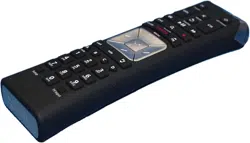
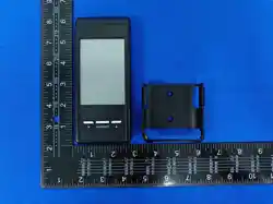
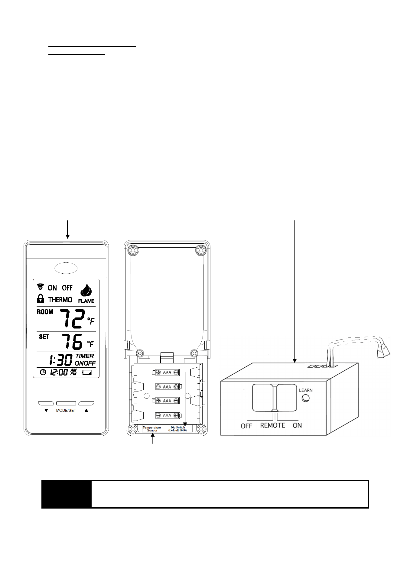
RCB09A Transmitter Front and Back
Dip Switch (Default 0000)
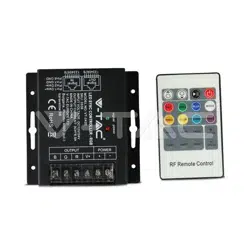
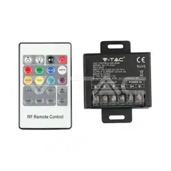
RCB09A Receiver
The user hand don’t closed to temperature sensor location to avoid it influence the detect temperature of sensor
WAR
NING
Do not use two (2) or more remote control systems in the same area with the same dip switch
settings, as they will communicate with each other. This may cause the appliances to
malfunction. It need to User setting new DIP Switch ID
Page 3 of 8
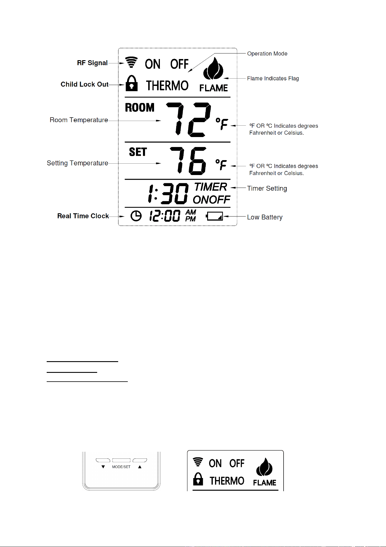
LCD - Liquid Crystal Display
1. Low Battery - Battery power is low. Replace batteries within 2 weeks.
2. TIMER On Setting- It Indicates time remaining before system shuts off, when timer-programmed;
9-hour maximum setting.
3. MODE- Indicates operation MODE of system.
a) ON indicates the system is on, either manually or thermostatically.
b) OFF indicates the entire system is turned off,
c) THERMO indicates the system will automatically cycle on/off, depending on programmed
4. SET- Indicates desire SET room temperature for THERMO operation
5. FLAME – Indicates burner/valve in operation.
6. CLOCK – Indicates the current time in AM/PM
7. ROOM – Indicates CURRENT room temperature.
8.
℉
– indicates degrees Fahrenheit (
ºC
indicates degrees Celsius).
9. LOCK – Child lock out.
OPERATIONS:
Transmitter:
MODE Operate Setting:
To operate the system, press the”MODE/SET” button or press the “MODE Section” on
The LCD screen on the front of the transmitter to select the operational MODE desired.
1) ON indicates the entire system is turned ON,
2) THERMO indicates the system will automatically cycle ON/OFF, depending on programmed set Temperature.
3) OFF indicates the entire system is turned OFF.
”MODE/SET” button “MODE SECTION” on LCD screen
Page 4 of 8
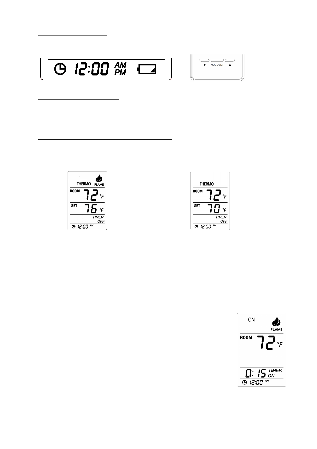
Real Time Clock Setting:
Press and Hold the “Clock Section” on The LCD screen on the bottom of the transmitter for 3 second, the clock
flag flashing indicates Real Time Clock Setting is active status, press “UP” or “DN” button to adjust the Real
Time Clock. And then press “MODE/SET” button to finish setting the Clock.
SETTING °F and °C SCALE:
The factory setting for temperature is °F. To change this setting to °C, first press and hold the UP button and the
DOWN button on the transmitter at the same time. Follow this same procedure to change from °C back to °F.
When changing between the °F and °C scales,
SETTING DESIRED ROOM TEMPERATURE
:
This remote control system can be thermostatically controlled when the transmitter is in the THERMO mode
(THERMO must be displayed on the screen). To set the DESIRED room temperature, press the MODE/SET
button or press the “MODE Section” on the LCD to place the transmitter into THERMO mode, then press the
UP or DOWN button to setting the desired room temperature. The highest SET temperature is 99°F (32°C).
In Thermo Mode: In Thermo Mode:
Setting Room Temperature> Room Temperature Setting Room Temperature< Room Temperature
Flame Flag is on and control system is ON
Flame Flag is off and control system is OFF
1.
There may be a slight delay in the response of the unit (on/off) to a temperature setting as room
temperature is monitored every 3 minutes.
Operational note: To conserve battery power, the remote
monitored room temperature every 3 minutes and
transmit the RF signal to Receiver.
SETTING THE COUNTDOWN TIMER:
This remote control system can operate with a built-in countdown timer when the transmitter is in the ON or
THERMO modes (THERMO or ON must be displayed on the screen).
1. Touch the word TIMER on the LCD screen of the transmitter for more than two
seconds. The minimum 0:15 minute setting on the will begin to flash.
2. Press the UP or DOWN button to begin advancing through each of the countdown time
options. Available countdown times are 15 minutes, 30 minutes, 45 minutes, 1 hour, 1:30
minutes, 2 hours, 2:30 minutes, and each additional half-hour up to nine hours.
3. Press the MODE/SET button do the Timer setting, if the system is ON. It will remain
on until the time has expired. If the system is in the THERMO mode, it will cycle on and
off, as the room temperature requires until the “time” has expired.
OPERATIONAL NOTE: When the timer is used in the THERMO mode, the THERMO operation will
discontinue when the “time” has expired. System will return to the OFF position.

Page 5 of 8
LOW/BATTERY INDICATOR
The battery ICON on the bottom and right side of the LCD screen will appear when battery
power has dropped significantly. At this time, approximately 2 weeks of battery power
remains until the transmitter may experience partial or complete loss of functions.
Child-proof protection:
1. Press and hold “MODE/SET” and “UP” buttons at same time for 5 seconds to
activate child-proof mode. The LOCK ICON will appear on the LCD screen. The
buttons will deactivated.
2. The remote control will not work until child-proof mode is deactivated by pressing
the “MODE/SET” and “UP” buttons at same time for 5 seconds again to exit
child-proof mode.
Transmitter Wall Bracket
The transmitter can be hung on a wall using the Wall Bracket provided. If the Wall Bracket is installed on a
solid wood wall, drill 1/8” pilot holes and install with the screws provided. If it is installed on a laster/wallboard
wall, first drill two 1/4” holes into the wall. Then use a hammer to tap in the two plastic wall anchors flush with
the wall; then install the screws provided.
TRANSMITTER
The remote control operates, on RF (radio frequency) signals that are sent by the TRANSMITTER (remote) to
the RECEIVER that operates the appliance. It is recommended that the TRANSMITTER always be located
within the 30-foot operating range, preferably in the same room in which the appliance is located.
WAR
NING
Make sure that the wires do not contact the appliances any place other than at the terminals.
Exposure to temperatures higher than 250℉(105℃) may cause the receiver to malfunction or
cause a fire hazard.
Receiver:
Begin by installing (4) AA-size batteries. Slide open the battery cover on
receiver. It is recommended that ALKALINE batteries always be used for
this product. Be sure the batteries are installed with the (+) and (-) ends
facing the correct direction. Close battery cover
NOTE: The remote receiver will only respond to the transmitter when the
3-position slide button on the remote receiver is in the REMOTE
position. The remote receiver houses the microprocessor that responds to
commands from the transmitter to control system operation
Page 6 of 8
FUNCTIONS
:
1) with the slide switch in the”
ON
” position (toward the LEARN button), the system will remain ON
until the slide switch is placed in the OFF or REMOTE position.
2) with the slide switch in the”
REMOTE
” position (centered), the system will only operate if the
remote receiver receives commands from the transmitter.
3) with the slide switch in the”
OFF
” position (away from the LEARN button), the system is OFF.
It is suggested that the slide switch be placed in the OFF position if you will be away from your home for
an extended period of time. If the remote receiver is mounted out of children’s reach, placing the slide
switch in the OFF position
Also functions as a safety “lock-out” by both turning the system off and rendering the remote receiver
inoperative
Installation
The remote receiver can be either wall-mounted in a standard plastic switch box (not metal) or placed on or near
the fireplace hearth. Preferably, the remote receiver should be wall-mounted in a plastic switch box, as this will
protect its electronic components from the heat produced by the gas appliance. The remote receiver should be
kept away from temperatures exceeding 130º F. Battery life is also significantly shortened if batteries are
exposed to temperatures 130ºF or higher. Before installation make sure the remote receiver slide switch is in the
OFF position.
Wall Mounting
When wall mounting the remote receiver, longer wires (not included) are required to connect to the gas valve or
electronic module. These wires must: Be at least 18 Gauge (AWG) • Be no longer than 20’ • Have no splices
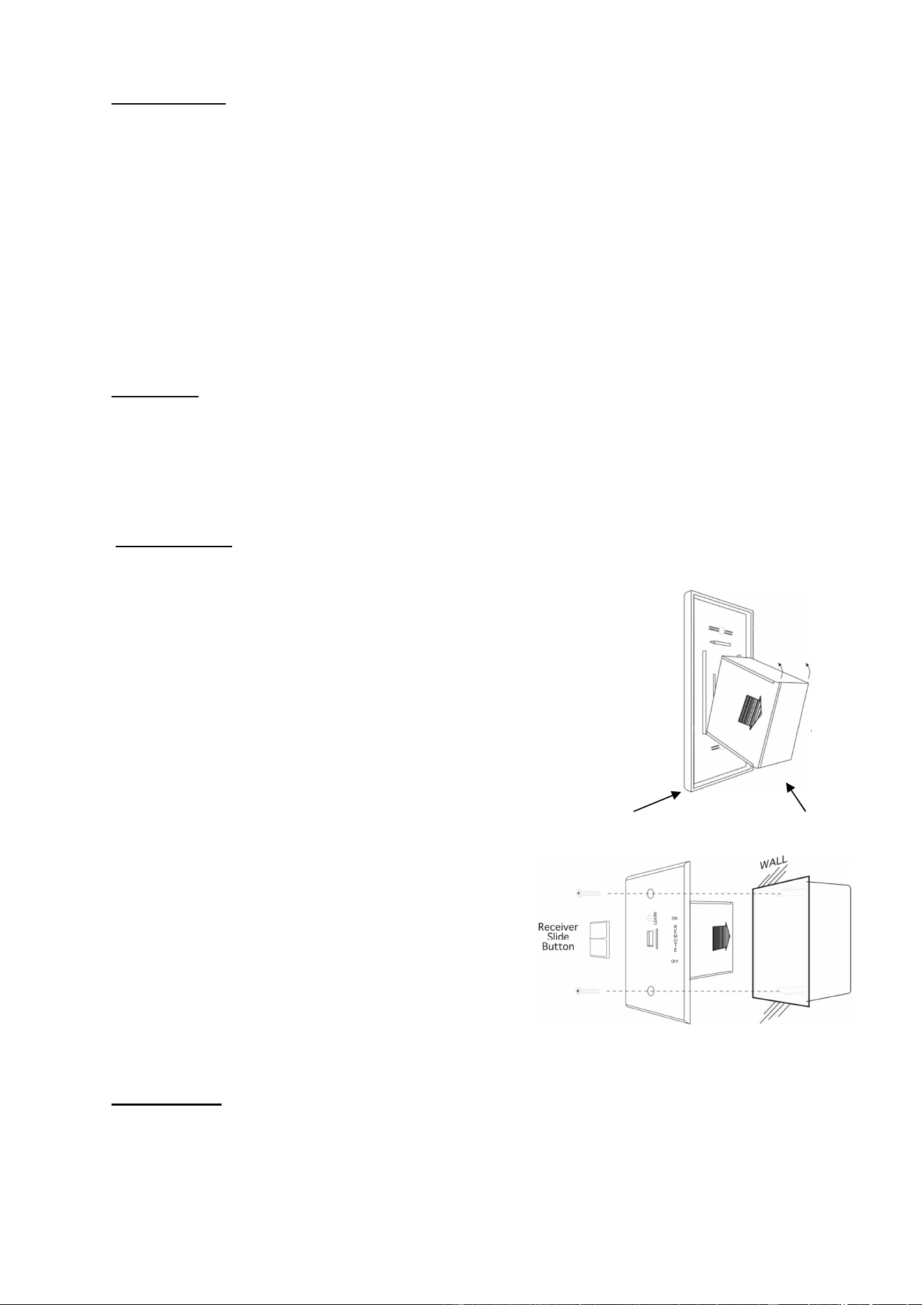
To attach wall cover plate to receiver box:
1. Position the receiver as shown in diagram to the right with lower tab on wall cover
Plate into groove of receiver (Make sure the LEARN hole on cover plate properly
Aligns with remote receiver)
2. Pull receiver up and snap into top tab of cover plate.
3. Position the wall cover plate so the word ON is facing up.
4. Install the remote receiver into the plastic switch box using the two
Long screws provided. Push the slide Button over the receiver slide
Wall plate Receiver
NOTE: The remote receiver will only respond to the transmitter
when the 3-position slide button on the remote receiver is in the
REMOTE position. If the system does not respond to the battery
transmitter on initial use, see LEARNING TRANSMITTER TO
RECEIVER, and recheck battery positions in the remote receiver
.
Cover plate Plastic switch box
Hearth Mount
The remote receiver can be placed on the fireplace hearth or under the fireplace, behind the control access panel.
Position where the ambient temperature inside the receiver case does not exceed 130 ℉.
NOTE: Black Slide Button is used for Hearth Mount applications.
Page 7 of 8
WIRING INSTRUCTIONS
A qualified electrician or a gas technician who is familiar with the gas appliance and gas valves that will be
operated by this remote should install the remote control system. Incorrect wiring connections WILL cause
damage to the gas valve or electronic module operating the gas appliance and may also damage the remote
receiver.
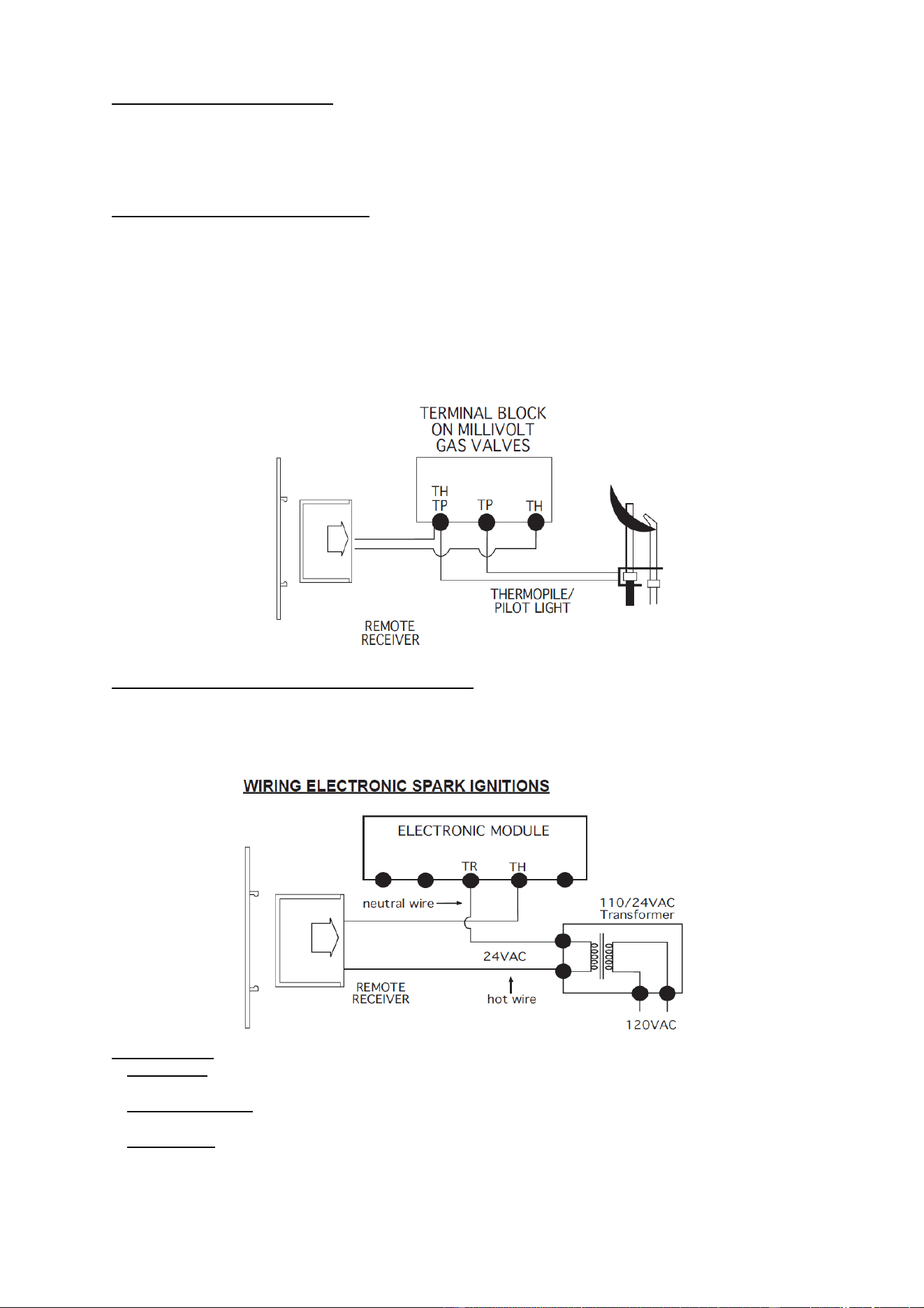
WIRING MILLIVOLT VALVES
The remote receiver is connected to the millivolt valve using the TH (thermostat) terminals on the terminal
block on the millivolt gas valve. Connect 18 gauge stranded or solid wires from the remote receiver to the gas
valve.
Operation of the remote receiver is similar to that of a thermostat in that both turn the gas valve on and off
Based on input signals. A thermostat’s input signals are different temperatures. The remote receiver’s input
Signals come from the transmitter.
Connect each of the two wires leading from the TH and TH/TP terminals on the millivolt gas valve to either of
The two wire terminals on the remote receiver. Normally it does not matter which wires go to which terminal.
WIRING ELECTRONIC SPARK IGNITIONS
The remote control receiver can be connected, in series, to a 24VAC transformer to the TR
(transformer) terminal on the ELECTRONIC MODULE. Connect the hot wire from the 24VAC
transformer to either of the wire terminals on the remote receiver. Connect another wire between the
other receiver wire terminal and the TH (thermostat) terminal on the ELECTRONIC MODULE.
Slide Switch
:
1. ON position: the system will remain on until the slide switch is placed in the OFF or REMOTE position.
2. REMOTE position: the system will only operate if the remote receiver receives a signal from the transmitter.
3. OFF position: the system is off. The slide switch should be placed in the OFF position if you will be
away for an extended period of time. If the remote receiver is mounted out of children’s reach, the OFF
position also functions as a safety device by both turning the system off and rendering the receiver inoperable.

Page 8 of 8
Testing Your New Remote System
1. Light your gas appliance following the appliance lighting instructions that come with the appliance. Confirm
that the pilot light is on; it must be in operation for the remote control to operate the main gas valve. Appliance
control knob must be in the ON position. Appliance ON/OFF switch must be in ON position.
2. Slide the 3 position button on the remote receiver to the ON position. The main gas flame should ignite.
3. Slide the button to OFF. The flame should extinguish (the pilot light will remain on).
4. Slide the button to REMOTE (the center position), then press the transmitter to turn the system to ON. The
main gas flame should ignite.
5.
Press the transmitter to turn the system to OFF. The flame should extinguish (the pilot light will remain on).
TROUBLESHOOTING
Symptom Causes Action
Battery icon on LCD on
transmitter.
Low Battery Replace batteries.
LCD Display is blank
Low Battery Check battery installation and replace
batteries.
Receiver emits the beep in
every minute
Low Battery Replace batteries.
Receiver cannot receive
signal.
1. Receiver is installed in an enclosure
2. Low Battery for Transmitter or
Low Battery for Receiver
1. Make sure the receiver is not inside a
tight enclosure.
2. Replace batteries.
Appliance does not come
on.
1. DIP (Privacy) switch setting on
transmitter does not match receiver
1. Make sure the transmitter is matched to
the receiver.
2. Transmitter measures temperature
exceeding 99 degrees and shows
“HI” on LCD display.
2. Move transmitter to a cooler place and
wait until temperature drops below 99
degree.
3. Distance between the transmitter
and receiver is more than 30 feet
3. Make sure the operating distance is less
than 30 feet

FCC Statement
1. This device complies with Part 15 of the FCC Rules. Operation is subject to the following two conditions:
(1) This device may not cause harmful interference.
(2) This device must accept any interference received, including interference that may cause undesired operation.
2. Changes or modifications not expressly approved by the party responsible for compliance could void the user's authority to operate
the equipment.
NOTE:
This equipment has been tested and found to comply with the limits for a Class B digital device, pursuant to Part 15 of the FCC Rules.
These limits are designed to provide reasonable protection against harmful interference in a residential installation.
This equipment generates uses and can radiate radio frequency energy and, if not installed and used in accordance with the
instructions, may cause harmful interference to radio communications. However, there is no guarantee that interference will not occur
in a particular installation. If this equipment does cause harmful interference to radio or television reception, which can be determined
by turning the equipment off and on, the user is encouraged to try to correct the interference by one or more of the following measures:
Reorient or relocate the receiving antenna.
Increase the separation between the equipment and receiver.
Connect the equipment into an outlet on a circuit different from that to which the receiver is connected.
Consult the dealer or an experienced radio/TV technician for help.
To comply with RF exposure requirements, a minimum separation distance of 20mm must be maintained between the user’s body and
the handset, including the antenna.
IC STATEMENT
This device complies with Industry Canada licence-exempt RSS standard(s)
Operation is subject to the following two conditions:
(1) This device may not cause interference, and
(2) This device must accept any interference, including interference that may cause undesired
operation of the device.
This equipment complies with IC radiation exposure limits set forth for an uncontrolled
environment. End user must follow the specific operating instructions for satisfying RF
exposure compliance. This transmitter must not be co-located or operating in conjunction with
any other antenna or transmitter.
Le présent appareil est conforme aux CNR d'Industrie Canada applicables aux appareils radio
exempts de licence.
Ce dispositif est conforme aux normes autoriser-exemptes du Canada RSS d'industrie
L'exploitation est autorisée aux deux conditions suivantes :
(1) l'appareil ne doit pas produire de brouillage, et
(2) l'utilisateur de l'appareil doit accepter tout brouillage radioélectrique subi, même si le
brouillage est susceptible d'en compromettre le fonctionnement.Cet équipement
est conforme avec l'exposition aux radiations IC définies pour un environnement
non contrôlé. L'utilisateur final doit respecter les instructions de fonctionnement spécifiques pour satisfaire la conformité aux
expositions RF. Cet émetteur ne doit pas être co-localisées ou opérant en conjonction avec une autre antenne ou transmetteur.