Part Number 000018624 Rev 00 4/26
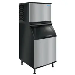
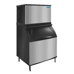
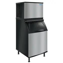
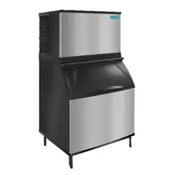
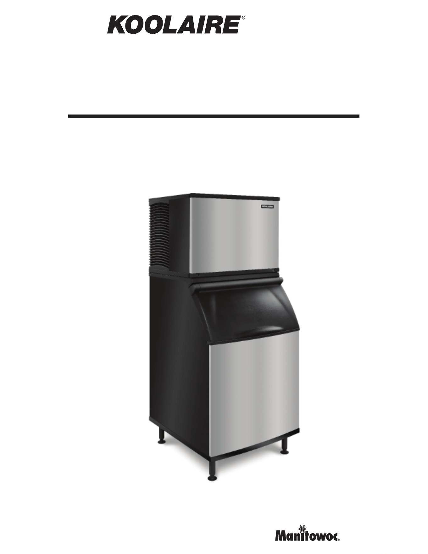
K, KP & KT Models
Air/Water/Remote Condenser
Modular Ice Machines
Technician’s Handbook


Part Number 000018624 Rev 00 4/26 Modular - 3
Safety Notices
Read these precautions to prevent personal injury:
• Read this manual thoroughly before operating,
installing or performing maintenance on the
equipment. Failure to follow instructions in this
manual can cause property damage, injury or death.
• Routine adjustments and maintenance procedures
outlined in this manual are not covered by the
warranty.
• Proper installation, care and maintenance are essential
for maximum performance and trouble-free operation
of your equipment.
• Visit our website www.kool-aire.com for manual
updates, translations, or contact information for
service agents in your area.
• This equipment contains high voltage electricity and
refrigerant charge. Installation and repairs are to be
performed by properly trained technicians aware of
the dangers of dealing with high voltage electricity
and refrigerant under pressure. The technician
must also be certified in proper refrigerant handling
and servicing procedures. All lockout and tag out
procedures must be followed when working on this
equipment.
• This equipment is intended for indoor use only. Do not
install or operate this equipment in outdoor areas.
• As you work on this equipment, be sure to pay close
attention to the safety notices in this handbook.
Disregarding the notices may lead to serious injury
and/or damage to the equipment.
4 - Modular Part Number 000018624 Rev 00 4/26
Definitions
DANGER
Indicates a hazardous situation that, if not avoided, will
result in death or serious injury. This applies to the most
extreme situations.
n
Warning
Indicates a hazardous situation that, if not avoided,
could result in death or serious injury.
,
Caution
Indicates a hazardous situation that, if not avoided,
could result in minor or moderate injury.
Notice
Indicates information considered important, but not
hazard-related (e.g. messages relating to property
damage)
NOTE: Indicates useful, extra information about the
procedure you are performing.
We reserve the right to make product improvements at
any time. Specifications and design are subject to change
without notice.
Part Number 000018624 Rev 00 4/26 Modular - 5
n
Warning
Follow these electrical requirements during
installation of this equipment.
• All field wiring must conform to all applicable
codes of the authority having jurisdiction. It is
the responsibility of the end user to provide the
disconnect means to satisfy local codes. Refer to
rating plate for proper voltage.
• This appliance must be grounded.
• This equipment must be positioned so that the plug
is accessible unless other means for disconnection
from the power supply (e.g., circuit breaker or
disconnect switch) is provided.
• Check all wiring connections, including factory
terminals, before operation. Connections can
become loose during shipment and installation.
DANGER
Do not operate equipment that has been misused,
abused, neglected, damaged, or altered/modified
from that of original manufactured specifications. This
appliance is not intended for use by persons (including
children) with reduced physical, sensory or mental
capabilities, or lack of experience and knowledge,
unless they have been given supervision concerning
use of the appliance by a person responsible for their
safety. Do not allow children to play with, clean or
maintain this appliance without proper supervision.
6 - Modular Part Number 000018624 Rev 00 4/26
n
Warning
Follow these precautions to prevent personal injury
during installation of this equipment:
• Installation must comply with all applicable
equipment fire and health codes with the authority
having jurisdiction.
• Connect to a potable water supply only.
• To avoid instability the installation area must be
capable of supporting the combined weight of the
equipment and product. Additionally the equipment
must be level side to side and front to back.
• Remove all removable panels before lifting and
installing and use appropriate safety equipment
during installation and servicing. Two or more
people are required to lift or move this appliance to
prevent tipping and/or injury.
• Do not damage the refrigeration circuit when
installing, maintaining or servicing the unit.
• This equipment contains refrigerant charge.
Installation of the line sets must be performed by
a properly trained and EPA certified refrigeration
technician aware of the dangers of dealing with
refrigerant charged equipment.
• Ice machines require a deflector when installed on
an ice storage bin. Prior to using a non-OEM ice
storage system with this ice machine, contact the
bin manufacturer to assure their ice deflector is
compatible.
• Prior to installing a non-OEM ice storage system
with this ice machine, follow the manufacturers
installation procedures and verify the location and
installation meets the local/national mechanical
codes and stability requirements.

Part Number 000018624 Rev 00 4/26 Modular - 7
n
Warning
Follow these precautions to prevent personal injury
while operating or maintaining this equipment.
• Refer to nameplate to identify the type of refrigerant
in your equipment.
• Only trained and qualified personnel aware of the
dangers are allowed to work on the equipment.
• Read this manual thoroughly before operating,
installing or performing maintenance on the
equipment. Failure to follow instructions in this
manual can cause property damage, injury or death.
• Crush/Pinch Hazard. Keep hands clear of moving
components. Components can move without
warning unless power is disconnected and all
potential energy is removed.
• Moisture collecting on the floor will create a
slippery surface. Clean up any water on the floor
immediately to prevent a slip hazard.
• Never use sharp objects or tools to remove ice or
frost. Do not use mechanical devices or other means
to accelerate the defrosting process.
• When using cleaning fluids or chemicals, rubber
gloves and eye protection (and/or face shield) must
be worn.
• Objects placed or dropped in the bin can affect
human health and safety. Locate and remove any
objects immediately.
8 - Modular Part Number 000018624 Rev 00 4/26
DANGER
Follow these precautions to prevent personal injury
during use and maintenance of this equipment:
• It is the responsibility of the equipment owner to
perform a Personal Protective Equipment Hazard
Assessment to ensure adequate protection during
maintenance procedures.
• Do Not Store Or Use Gasoline Or Other Flammable
Vapors Or Liquids In The Vicinity Of This Or Any Other
Appliance. Never use flammable oil soaked cloths or
combustible cleaning solutions for cleaning.
• All covers and access panels must be in place and
properly secured when operating this equipment.
• Risk of fire/shock. All minimum clearances must be
maintained. Do not obstruct vents or openings.
• Failure to disconnect power at the main power supply
disconnect could result in serious injury or death.
The power switch DOES NOT disconnect all incoming
power.
• All utility connections and fixtures must be maintained
in accordance with the authority having jurisdiction.
• Turn off and lockout all utilities (gas, electric, water)
according to approved practices during maintenance
or servicing.
• Do not store or use electrical appliances inside the ice
machine or ice storage areas.
Part Number 000018624 Rev 00 4/26 Modular - 9
DANGER
Follow these flammable refrigeration system
requirements during installation, use or repair of this
equipment:
• Refer to nameplate - Ice machine models may
contain up to 500 grams of R290 (propane)
refrigerant. R290 (propane)is flammable in
concentrations of air between approximately 2.1%
and 9.5% by volume (LEL lower explosion limit and
UEL upper explosion limit). An ignition source at
a temperature higher than 470°C is needed for a
combustion to occur. Refer to nameplate to identify
the type of refrigerant in your equipment.
• To minimize the risk of ignition due to improper
installation, replacement parts or service
procedures, only refrigeration technicians with
flammable refrigerant training who are aware of the
dangers of dealing with high voltage electricity and
refrigerant under pressure are allowed to work on
this equipment.
• All replacement parts must be like components
obtained from the equipment manufacturers
authorized replacement part network.
• This equipment must be installed in accordance with
the ASHRAE 15 Safety Standard for Refrigeration
Systems.
• This equipment can not be installed in corridors or
hallways of public buildings.
• Installation must comply with all applicable
equipment fire and health codes with the authority
having jurisdiction.
10 - Modular Part Number 000018624 Rev 00 4/26
DANGER
Follow these flammable refrigeration system
requirements during installation, use or repair of this
equipment:
• Minimum room size may be required; refer to ice
machine label.
• Multiple R290 units can be installed in a single room
but their cumulative refrigerant charge must be
considered when determining safe room size.
• All lockout and tag out procedures must be followed
when working on this equipment.
• This equipment contains high voltage electricity
and refrigerant charge. Shorting electrical wires to
refrigeration tubing may result in an explosion. All
electrical power must be disconnected from the
system before servicing the system. Refrigerant
leaks, can result in serious injury or death from
explosion, fire, or contact with refrigerant or
lubricant mists.
• Do not damage the refrigeration circuit when
installing, maintaining or servicing the unit. Never
use sharp objects or tools to remove ice or frost.
Do not use mechanical devices or other means to
accelerate the defrosting process.
• Well-ventilated areas are recommended for
installation and storage.
• Leak pressure, leak hole size, wind speed, and the
presence of objects like furniture within the room
can also affect the concentration and distribution of
R290 during a leak.
Part Number 000018624 Rev 00 4/26 Modular - 11
DANGER
Follow these precautions to prevent personal injury
during use and maintenance of this equipment:
• Units with two power cords must be plugged
into individual branch circuits. During movement,
cleaning or repair it is necessary to unplug both
power cords.
• Never use a high-pressure water jet for cleaning
on the interior or exterior of this unit. Do not use
power cleaning equipment, steel wool, scrapers or
wire brushes on stainless steel or painted surfaces.
• Two or more people are required to move this
equipment to prevent tipping.
• Locking the front casters after moving is the
owner’s and operator’s responsibility. When casters
are installed, the mass of this unit will allow it to
move uncontrolled on an inclined surface. These
units must be tethered/secured to comply with all
applicable codes.
• The on-site supervisor is responsible for ensuring
that operators are made aware of the inherent
dangers of operating this equipment.
• Do not operate any appliance with a damaged cord
or plug. All repairs must be performed by a qualified
service company.

12 - Modular Part Number 000018624 Rev 00 4/26
THIS PAGE INTENTIONALLY LEFT BLANK

Part Number 000018624 Rev 00 4/26 Modular - 13
Table of Contents - Modular
Safety Notices . . . . . . . . . . . . . . . . . . . . . . . . . . . . . . .3
Definitions . . . . . . . . . . . . . . . . . . . . . . . . . . . . . .4
General Information
Model Numbers . . . . . . . . . . . . . . . . . . . . . . . . . . . .19
KP Models . . . . . . . . . . . . . . . . . . . . . . . . . . . . .19
KT Models . . . . . . . . . . . . . . . . . . . . . . . . . . . . .19
K Models . . . . . . . . . . . . . . . . . . . . . . . . . . . . . .20
Ice Machine Warranty Information . . . . . . . . . . . .21
Warranty . . . . . . . . . . . . . . . . . . . . . . . . . . . . . . . . . .21
Warranty Registration . . . . . . . . . . . . . . . . . . . . . . .21
How to Read a Model Number . . . . . . . . . . . . . . . .22
Installation
Location of Ice Machine . . . . . . . . . . . . . . . . . . . . . .23
Ice Machine Clearance Requirements . . . . . . . . . .24
Minimum Room Size. . . . . . . . . . . . . . . . . . . . . . . . .25
Refrigerant Charge . . . . . . . . . . . . . . . . . . . . . . . . . .25
Ice Machine Heat of Rejection . . . . . . . . . . . . . . . .26
Leveling the Ice Machine . . . . . . . . . . . . . . . . . . . . .27
Electrical Requirements . . . . . . . . . . . . . . . . . . . . . .28
Water Service/Drains . . . . . . . . . . . . . . . . . . . . . . . .30
Water Supply . . . . . . . . . . . . . . . . . . . . . . . . . . .30
Drain Connections. . . . . . . . . . . . . . . . . . . . . . .31
Cooling Tower Applications . . . . . . . . . . . . . . .31
Water Supply and Drain Line Sizing/
Connections . . . . . . . . . . . . . . . . . . . . . . . . . . .32
Remote Condenser KT Models. . . . . . . . . . . . .33
Remote Condenser K Models. . . . . . . . . . . . . .34

14 - Modular Part Number 000018624 Rev 00 4/26
Maintenance
De-scaling and Sanitizing . . . . . . . . . . . . . . . . . . . . .39
General. . . . . . . . . . . . . . . . . . . . . . . . . . . . . . . .39
Ice Machine Inspection. . . . . . . . . . . . . . . . . . .40
Exterior Cleaning . . . . . . . . . . . . . . . . . . . . . . . .40
Remedial De-scaling . . . . . . . . . . . . . . . . . . . . .40
Detailed De-scaling/Sanitizing . . . . . . . . . . . . .40
Detailed De-scaling and Sanitizing Procedure 41
Toggle Switch Operation. . . . . . . . . . . . . . . . . .41
Sanitizing Procedure . . . . . . . . . . . . . . . . . . . . .44
Remove Parts for De-scaling/Sanitizing. . . . . .46
Remedial De-scaling Procedure. . . . . . . . . . . . . . . .48
Door Removal . . . . . . . . . . . . . . . . . . . . . . . . . . . . . .49
Cleaning the Air Filter & AirCondenser . . . . . . . . .50
Removal from Service/Winterization . . . . . . . . . . .51
Air-cooled Models . . . . . . . . . . . . . . . . . . . . . . .51
Water-cooled Models . . . . . . . . . . . . . . . . . . . .51
Operation
Ice Making Sequence of Operation. . . . . . . . . . . . .53
Control Board Timers . . . . . . . . . . . . . . . . . . . .54
Service Limits. . . . . . . . . . . . . . . . . . . . . . . . . . .55
Energized Parts Chart . . . . . . . . . . . . . . . . . . . .57
Operational Checks. . . . . . . . . . . . . . . . . . . . . . . . . .59
Ice Thickness Check. . . . . . . . . . . . . . . . . . . . . .59
Minimum/Maximum Slab Weights . . . . . . . . .60

Part Number 000018624 Rev 00 4/26 Modular - 15
Troubleshooting
Service Limits. . . . . . . . . . . . . . . . . . . . . . . . . . . . . . .61
Service Limit 1 . . . . . . . . . . . . . . . . . . . . . . . . . .61
Service Limit 2 . . . . . . . . . . . . . . . . . . . . . . . . . .61
Service Limit 3 . . . . . . . . . . . . . . . . . . . . . . . . . .63
Service Limit Checklist . . . . . . . . . . . . . . . . . . .65
Control Board Test Mode . . . . . . . . . . . . . . . . . . . . .69
Diagnosing an Ice Machine that Will Not Run. . . .70
Troubleshooting By Symptom . . . . . . . . . . . . . . . . .71
Symptom #1 . . . . . . . . . . . . . . . . . . . . . . . . . . .72
Symptom #2 . . . . . . . . . . . . . . . . . . . . . . . . . . .74
Symptom #3 - Remote Condenser. . . . . . . . .105
Symptom #3 - Air or Water-Cooled . . . . . . . .107
Symptom #4. . . . . . . . . . . . . . . . . . . . . . . . . . .109
Component Check Procedures
Main Fuse . . . . . . . . . . . . . . . . . . . . . . . . . . . . . . . .111
Bin Switch . . . . . . . . . . . . . . . . . . . . . . . . . . . . . . . .112
Float Switch . . . . . . . . . . . . . . . . . . . . . . . . . . . . . . .114
Compressor Electrical Diagnostics . . . . . . . . . . . .116
PTCR . . . . . . . . . . . . . . . . . . . . . . . . . . . . . . . . . . . . .118
Fan Cycle Control. . . . . . . . . . . . . . . . . . . . . . . . . . .120
High Pressure Cutout (HPCO) Control. . . . . . . . . .121
Refrigeration Components. . . . . . . . . . . . . . . . . . .122
Head Pressure Control Valve . . . . . . . . . . . . .122
Freeze Cycle Operation. . . . . . . . . . . . . . . . . .123
Harvest Cycle Operation. . . . . . . . . . . . . . . . .123
Harvest Pressure Regulating Valve. . . . . . . . .126
Water Regulating Valve . . . . . . . . . . . . . . . . . . . . .129
Refrigerant Recovery/Evacuation . . . . . . . . . . . . .130
Definitions . . . . . . . . . . . . . . . . . . . . . . . . . . . .130
Refrigerant Re-use Policy . . . . . . . . . . . . . . . .131
Recovery and Recharging Procedures . . . . .133
Remote Condenser Model Procedure . . . . . .137
Remote Charging Procedures. . . . . . . . . . . . .139

16 - Modular Part Number 000018624 Rev 00 4/26
System Contamination Cleanup . . . . . . . . . . . . . .140
Determining Severity of Contamination . . . .140
Cleanup Procedure . . . . . . . . . . . . . . . . . . . . .142
Severe System Contamination
Cleanup Procedure . . . . . . . . . . . . . . . . . . . . .143
Liquid Line Filter Driers . . . . . . . . . . . . . . . . . .144
Replacing Pressure Controls without
Removing Refrigerant Charge. . . . . . . . . . . . .145
Refrigerant Amounts . . . . . . . . . . . . . . . . . . . . . . .146
KP Models . . . . . . . . . . . . . . . . . . . . . . . . . . . .146
KT Models . . . . . . . . . . . . . . . . . . . . . . . . . . . .147
K Models . . . . . . . . . . . . . . . . . . . . . . . . . . . . .148
Charts
Cycle Times, 24 Hr. Ice Production and Refrigerant
Pressure Charts . . . . . . . . . . . . . . . . . . . . . . . . . . . .149
K0250 Series
K0250A Self-contained Air-cooled . . . . . . . . .150
K0300 Series
KP0300A Self-contained Air-cooled . . . . . . . .152
KT0300A Self-contained Air-cooled . . . . . . . .154
K0350 Series
K0350A Self-contained Air-cooled . . . . . . . . .156
K0350W Self-contained Water-cooled . . . . .158
K0400 Series
KP0400A Self-contained Air-cooled . . . . . . . .160
KP0400W Self-contained Water-cooled . . . .162
KT0400A Self-contained Air-cooled . . . . . . . .164
KT0400W Self-contained Water-cooled . . . .166
K0420 Series
K0420A Self-contained Air-cooled . . . . . . . . .168
K0420W Self-contained Water-cooled . . . . .170
KP0420A Self-contained Air-cooled . . . . . . . .172
KP0420W Self-contained Water-cooled . . . .174
KT0420A Self-contained Air-cooled . . . . . . . .176
KT0420W Self-contained Water-cooled . . . .178

Part Number 000018624 Rev 00 4/26 Modular - 17
K0500 Series
K0500A Self-contained Air-cooled . . . . . . . . .180
K0500W Self-contained Water-cooled . . . . .182
KP0500A Self-contained Air-cooled . . . . . . . .184
KP0500W Self-contained Water-cooled . . . .186
KT0500A Self-contained Air-cooled . . . . . . . .188
KT0500W Self-contained Water-cooled . . . .190
K0600 Series
K0600A Self-contained Air-cooled . . . . . . . . .192
K0600W Self-contained Water-cooled . . . . .194
K0700 Series
KP0700A Self-contained Air-cooled . . . . . . . .196
KP0700W Self-contained Water-cooled . . . .198
KT0700A Self-contained Air-cooled . . . . . . . .200
KT0700W Self-contained Water-cooled . . . .202
K1000 Series
K1000A Self-contained Air-cooled . . . . . . . . .204
K1000W Self-contained Water-cooled . . . . .206
K1000N Remote Air-cooled . . . . . . . . . . . . . .208
KP1000A Self-contained Air-cooled . . . . . . . .210
KP1000W Self-contained Water-cooled . . . .212
KT1000A Self-contained Air-cooled . . . . . . . .214
KT1000W Self-contained Water-cooled . . . .216
KT1000N Remote Air-cooled . . . . . . . . . . . . .218
K1350 Series
K1350A Self-contained Air-cooled . . . . . . . . .220
K1350W Self-contained Water-cooled . . . . .222
K1350N Remote Air-cooled . . . . . . . . . . . . . .224
K1700 Series
KT1700A Self-contained Air-cooled . . . . . . . .226
KT1700W Self-contained Water-cooled . . . .228
KT1700N Remote Air-cooled . . . . . . . . . . . . .230
K1800 Series
K1800A Self-contained Air-cooled . . . . . . . . .232
K1800N Remote Air-cooled . . . . . . . . . . . . . .234

18 - Modular Part Number 000018624 Rev 00 4/26
Diagrams
Wiring Diagrams . . . . . . . . . . . . . . . . . . . . . . . . . . .237
K & KT Models . . . . . . . . . . . . . . . . . . . . . . . . .238
KP Models . . . . . . . . . . . . . . . . . . . . . . . . . . . .252
Electronic Control Board . . . . . . . . . . . . . . . . . . . .256
KP & KT Models . . . . . . . . . . . . . . . . . . . . . . . .256
K Models . . . . . . . . . . . . . . . . . . . . . . . . . . . . .258
Refrigeration Tubing Schematics. . . . . . . . . . . . . .260
Part Number 000018624 Rev 00 4/26 Modular - 19
Model Numbers
This manual covers the following models:
KP MODELS
Self-Contained Air-Cooled Self-Contained Water-Cooled
KDP0300A ----
KYP0300A ----
KDP0400A KDP0400W
KYP0400A KYP0400W
KDP0420A KDP0420W
KYP0420A KYP0420W
KDP0500A KDP0500W
KYP0500A KYP0500W
KDP0700A KDP0700W
KYP0700A KYP0700W
KDP1000A KDP1000W
KYP1000A KYP1000W
KT MODELS
Self-Contained
Air-Cooled
Self-Contained
Water-Cooled
Remote
KDT0300A ---- ----
KYT0300A ---- ----
KDT0400A KDT0400W ----
KYT0400A KYT0400W ----
KDT0420A KDT0420W ----
KYT0420A KYT0420W ----
KDT0500A KDT0500W ----
KYT0500A KYT0500W ----
KDT0700A KDT0700W ----
KYT0700A KYT0700W ----
KDT1000A KDT1000W KDT1000N
KYT1000A KYT1000W KYT1000N
KDT1700A KDT1700W KYT1700N
KYT1700A KYT1700W KDT1700N
General Information
20 - Modular Part Number 000018624 Rev 00 4/26
K MODELS
Self-Contained
Air-Cooled
Self-Contained
Water-Cooled
Remote
KD0250A ---- ----
KY0250A ---- ----
KD0350A KD0350W ----
KY0350A KY0350W ----
KD0420A KD0420W ----
KY0420A KY0420W ----
KD0500A KD0500W ----
KY0500A KY0500W ----
KD0600A KD0600W ----
KY0600A KY0600W ----
KD1000A KD1000W KY1000N
KY1000A KY1000W KD1000N
KD1350A KD1350W KY1350N
KY1350A KY1350W KD1350N
KD1800A KD1800W KY1800N
KY1800A KY1800W KD1800N
Part Number 000018624 Rev 00 4/26 Modular - 21
Ice Machine Warranty Information
Warranty
For warranty information visit:
www.kool-aire.com/Service/Warranty
• Warranty Coverage Information
• Warranty Registration
• Warranty Verification
Warranty coverage begins the day the ice machine is
installed.
Warranty Registration
Completing the warranty registration process is a quick and
easy way to protect your investment.
Scan the QR code with your smart device or enter the link
in a web browser to complete your warranty registration.
www.kool-aire.com/Service/Warranty
Registering your product insures warranty coverage and
streamlines the process if any warranty work is required.
22 - Modular Part Number 000018624 Rev 00 4/26
How to Read a Model Number
ICE
MACHINE
SERIES
I
Indigo
U UnderCounter
K Koolaire
R Flake/Nugget
B
Big shot
S S-series
IB Ice Beverage
C Countertop
REFRIGERANT
TYPE
P
R290
(propane)
F R404A (four)
T R410A (ten)
B R600A (butane)
E
R134A (eight)
NOMINAL
PRODUCTION @
70/50
0300
produces
~300 #/day
0320 produces ~320 #/day
0350 produces
~350
#/day
etc. . .
Soo is stated
in
kg/day
CONDENSER TYPE
A air cooled
W water cooled
N
remote
(tradional)
C CVD (remote)
POWER CORD OPTION
Blank
juncon box
Z cord without
plug
B
NEMA
plug
(USA)
F schuko plug (EU)
G 13A blade (GBR)
I
oblique
V
blades
(AUS)
SPECIAL USE
Blank general use
Q coated condenser
H high pressure
M marine
P correconal
Ttop
air
discharge
X Luminice/Sanitaon
L
lever
V
space
maker
MARKET IDENTIFIER
Blank not market specific
S Saudi
Arabia (GCC)
K Korea (KC)
C China (CCC)
D
Germany (GS)
N
Brazil (InMetro)
ICE TYPE
R Regular
DDice
Y
Half-dice
F Flake
N Nugget
G
Gourmet
Blank for IB only
ELECTRICAL
CONFIGURATION
161
= 115/60/1
261 = 208-230/60/1
251 = 220-
240/50/1 (S=230)
263
=
208-
230/60/3
271 = 200/50-60/1
273 = 200/50-60/3
453 = 380-415/50/3
463 = 460/60/3
2= 22"
wide cabinet
#=
all other
#s
mean
producon
value
K Y T 1 0 0 0 A – 2 6 1 A
A/E alternate compressor

Part Number 000018624 Rev 00 4/26 Modular - 23
Location of Ice Machine
The location selected for the ice machine must meet the
following criteria. If any of these criteria are not met,
select another location.
• The location must be indoors and free of airborne and
other contaminants.
• Air temperature: Must be at least 35°F (2°C) but must
not exceed 110°F (43.4°C).
• The location must not be near heat-generating
equipment or in direct sunlight and protected from
weather.
• The location must be capable of supporting the weight
of the ice machine and a full bin of ice.
• The location must allow enough clearance for water,
drain, and electrical connections in the rear of the ice
machine.
• The location must not obstruct airflow through or
around the ice machine (condenser air flow is in
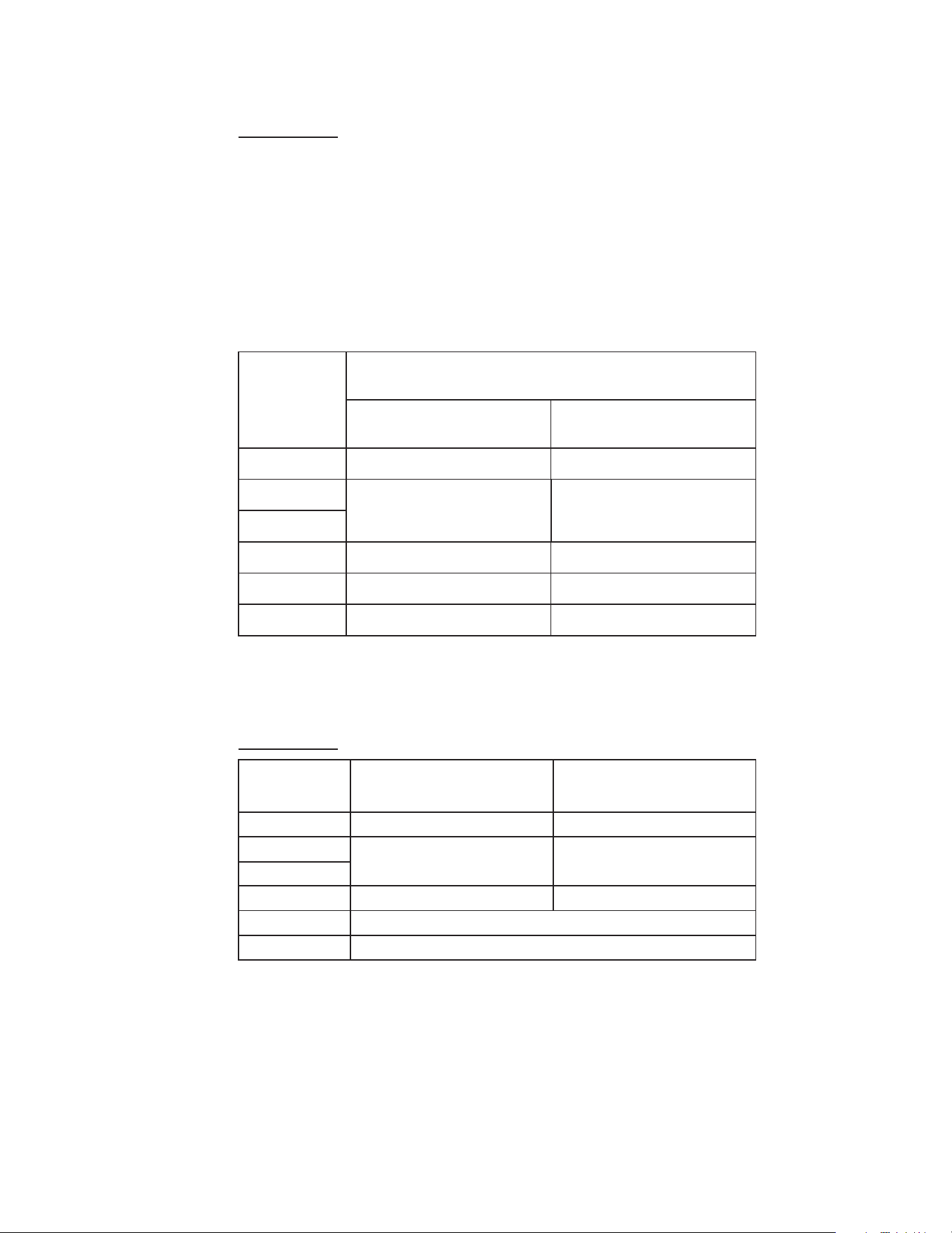
the back and out the sides). Refer to the chart for
clearance requirements.
• The ice machine must be protected if it will be
subjected to temperatures below 32°F (0°C). Failure
caused by exposure to freezing temperatures is not
covered by the warranty.
• All utilities must be within 6 feet (2 m) of the unit for
installation and serviceability.
Installation
24 - Modular Part Number 000018624 Rev 00 4/26
Ice Machine Clearance Requirements
n
Warning
Do not obstruct ice machine vents or openings.
KP0300
Self-Contained
Air-Cooled
Self-Contained
Water-Cooled
Top/Sides 16" (40.6 cm) n/a
Back 5" (12.7 cm)* n/a
KT0300
KP0420
Self-Contained
Air-Cooled
Self-Contained
Water-Cooled
Top/Sides 12" (30.5 cm) n/a
Back 5" (12.7 cm)* n/a
KT0400/KP0400
KT0420
KP0500/KT0500
KP0700/KT0700
KP1000/KT1000
KT1700
Self-Contained
Air-Cooled
Water-Cooled
and Remote
Top/Sides 8" (20.3 cm) 8" (20.3 cm)
Back 5" (12.7 cm) 5" (12.7 cm)
K0250
Self-Contained
Air-Cooled
Self-Contained
Water-Cooled
Top/Sides 12" (30.5 cm) n/a
Back 5" (12.7 cm)* n/a
K0350 - K0420
K0500 - K0600
K1000 - K1350
K1800
Self-Contained
Air-Cooled
Water-Cooled
and Remote
Top/Sides 8" (20.3 cm) 8" (20.3 cm)
Back 5" (12.7 cm) 5" (12.7 cm)
,
Caution
The ice machine must be protected if it will be
subjected to temperatures below 32°F (0°C). Failure
caused by exposure to freezing temperatures is not
covered by the warranty.
Part Number 000018624 Rev 00 4/26 Modular - 25
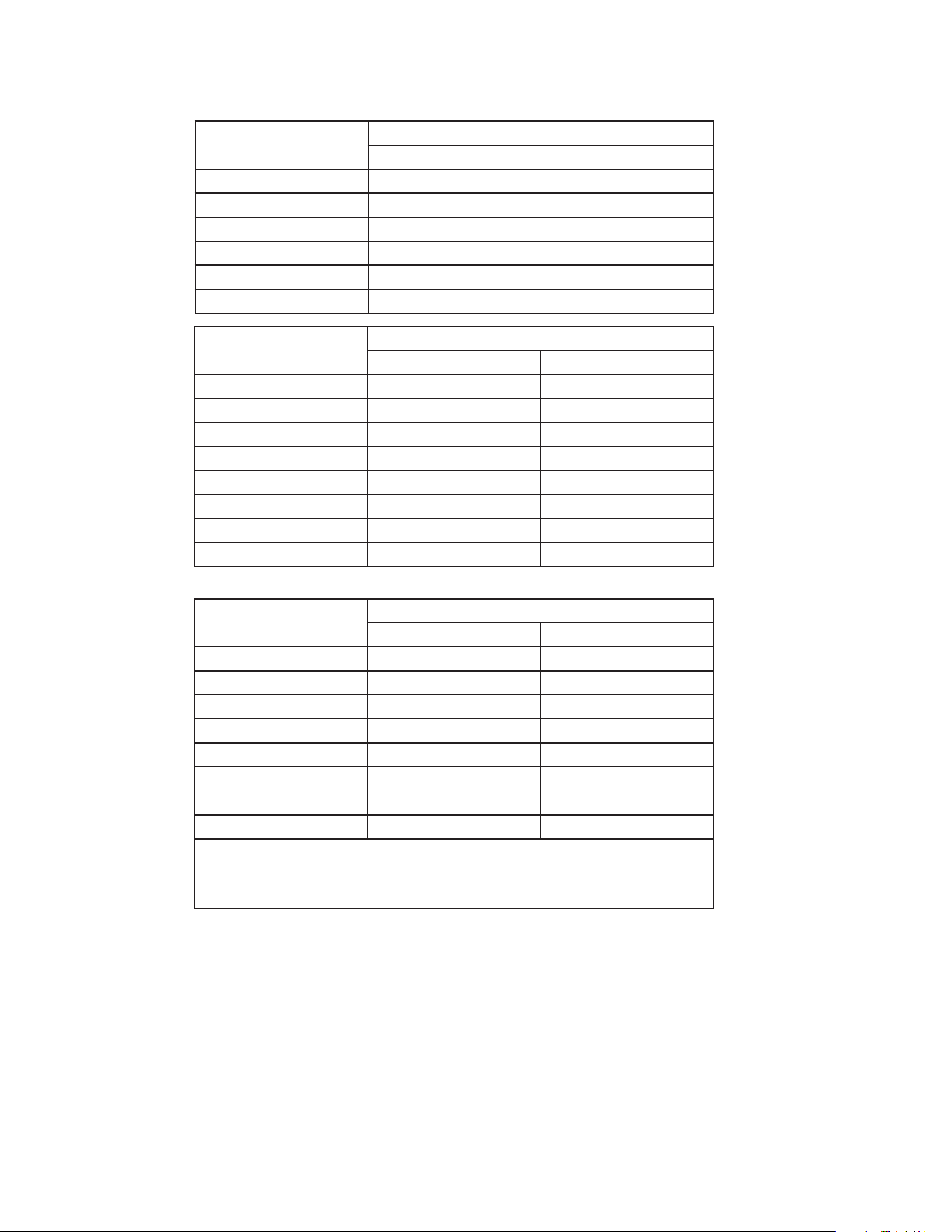
Minimum Room Size
R290 ONLY
In order to avoid the creation of a flammable gas-air
mixture if a leak in the refrigeration system occurs, the
size of the room in which the machine may be installed
depends on the amount of refrigerant used.
The ice machines listed below cannot be installed in
hallways, public corridors, public lobbies, evacuation
routes and/or small spaces.
Model
Minimum Room Size
sq ft (sq m)
Self-Contained
Air-Cooled
Self-Contained
Water-Cooled
KP0300 77.5 sq ft (7.2 sq m) ---
KP0400
87.0 sq ft (8.1 sq m) 77.5 sq ft (7.2 sq m)
KP0420
KP0500 77.5 sq ft (7.2 sq m) 93 sq ft (8.6 sq m)
KP0700 159 sq ft (14.8 sq m) 159 sq ft (14.8 sq m)
KP1000 206 sq ft (19.1 sq m) 206 sq ft (19.1 sq m)
Refrigerant Charge
R290 ONLY
Model
Self-Contained
Air-Cooled
Self-Contained
Water-Cooled
KP0300 5.3 oz (150 g) ---
KP0400
5.9 oz (170 g) 5.3 oz (150 g)
KP0420
KP0500 5.3 oz (150 g) 6.5 oz (180 g)
KP0700 10.9 oz (310 g)
KP1000 14.1 oz (400 g)
Multiple R290 units can be installed in a single room, but
their cumulative refrigerant charge needs to be considered
when determining the safe room size.
26 - Modular Part Number 000018624 Rev 00 4/26
Ice Machine Heat of Rejection
Series
Ice Machine
Heat of Rejection
1
Air Conditioning
2
Peak
KP0300 5120 6160
KP0400 7515 8905
KP0420 7516 8906
KP0500 7515 8905
KP0700 9470 11510
KP1000 14080 16340
Series
Ice Machine
Heat of Rejection
1
Air Conditioning
2
Peak
KT0300 4600 5450
KT0400 3800 6000
KT0420 5400 6300
KT0500 5300 6100
KT0700 12400 13900
KT1000 60 Hz 15400 17100
KT1000 50 Hz 14600 16200
KT1700 24700 29000
Series
Ice Machine
Heat of Rejection
1
Air Conditioning
2
Peak
K0250 4600 5450
K0350 3800 6000
K0420 5400 6300
K0500 5300 6100
K0600 9000 13900
K1000 17000 20700
K1350 23900 29000
K1800 29800 34700
1 BTU/Hour
2 Because the heat of rejection varies during the ice making
cycle, the figure shown is an average.
Ice machines, like other refrigeration equipment, reject
heat through the condenser. It is helpful to know the
amount of heat rejected by the ice machine when sizing air
conditioning equipment where self-contained air-cooled
ice machines are installed.

Part Number 000018624 Rev 00 4/26 Modular - 27
Leveling the Ice Machine
1. The leveling legs must be screwed into the bottom of
the bin as far as possible.
,
Caution
The legs must be screwed in tightly to prevent them
from bending.
2. Move the bin into its final position.
3. Use a level on top of the bin. Adjust each foot as
necessary and level from front to back and side to
side.

28 - Modular Part Number 000018624 Rev 00 4/26
Electrical Requirements
Voltage
The maximum allowable voltage variation is ±10% of the
rated voltage on the ice machine model/serial number
plate at start-up (when the electrical load is highest).
Fuse/Circuit Breaker
A separate electrical disconnect, which disconnects all
poles and has 1/8” (3 mm) contact separation, must be
provided for fixed wiring. Circuit breakers must be H.A.C.R.
rated in USA.
Total Circuit Ampacity
The total circuit ampacity is used to help select the wire
size of the electrical supply.
The wire size (or gauge) is also dependent upon location,
materials used, length of run, etc., so it must be
determined by a qualified electrician.
Refer to ice machine data plate, for electrical
requirements. The ice machine data plate information
overrides all other published data.
n
Warning
All wiring must conform to local, state and national
codes.
n
Warning
The ice machine must be grounded in accordance with
national and local electrical code.
Part Number 000018624 Rev 00 4/26 Modular - 29
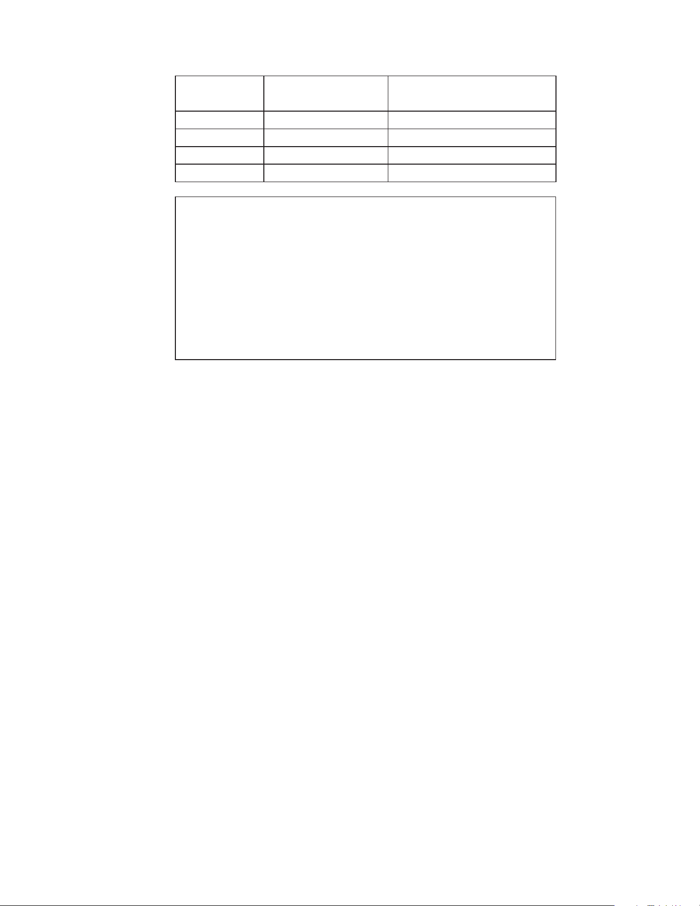
Minimum Power Cord Specifications
Maximum
Breaker Size
Minimum
Wire Size
Maximum
Length of Power Cord
15 amp 14 gauge 6 feet (1.83 m)
20 amp 12 gauge 6 feet (1.83 m)
30 amp 10 gauge 6 feet (1.83 m)
40 amp 8 gauge 6 feet (1.83 m)
n
Warning
Temporary electrical installations of more than
600 volts may be used only during periods of tests,
emergencies, or construction-like activities.
Temporary wiring must be removed immediately upon
completion of the project or purpose for which the
wiring was installed.
30 - Modular Part Number 000018624 Rev 00 4/26
Water Service/Drains
WATER SUPPLY
Local water conditions may require treatment of the water
to inhibit scale formation, filter sediment, and remove
chlorine odor and taste.
,
Caution
Do not apply heat to water inlet valve or water
drain fittings. Heating will damage the nonmetallic
connector. Do not over tighten fittings. Two turns after
hand tight is the maximum.
n
Warning
Connect to a potable water supply only. Plumbing
must conform to state, local and national codes.
WATER INLET LINES
Follow these guidelines to install water inlet lines:
• Do not connect the ice machine to a hot water supply.
Be sure all hot water restrictors installed for other
equipment are working. (Check valves on sink faucets,
dishwashers, etc.)
• If water pressure exceeds the maximum recommended
pressure, 80 psig (5.5 bar) obtain a water pressure
regulator from your Koolaire distributor.
• Install a water shut-off valve for ice making potable
water.
• Insulate water inlet lines to prevent condensation.
• If you are installing a water filter system, refer to the
Installation Instructions supplied with the filter system
for ice making water inlet connections.
,
Caution
Plumbing must conform to state and local codes

Part Number 000018624 Rev 00 4/26 Modular - 31
DRAIN CONNECTIONS
Follow these guidelines when installing drain lines to
prevent drain water from flowing back into the ice
machine and storage bin:
• Drain lines must have a 1.5-inch drop per 5 feet of run
(2.5 cm per meter), and must not create traps.
• The floor drain must be large enough to accommodate
drainage from all drains.
• Install a tee at the ice machine drain outlet and install
an 18.0” (46 cm) vent above the drain line.
• Insulate drain lines to prevent condensation.
• Vent the bin and ice machine drain to the atmosphere.
Do not vent the condenser drain on water-cooled
models.
COOLING TOWER APPLICATIONS
Water Cooled Models Only
A water-cooling tower installation does not require
modification of the ice machine. The water regulator valve
for the condenser continues to control the refrigeration
discharge pressure.
It is necessary to know the amount of heat rejected, and
the pressure drop through the condenser and water valves
(inlet to outlet) when using a cooling tower on an ice
machine.
• Water entering the condenser must not exceed 90°F
(32.2°C).
• Water flow through the condenser must not exceed
5 gallons (19 liters) per minute.
• Allow for a pressure drop of 7 psig (0.48 bar) between
the condenser water inlet and the outlet of the ice
machine.
• Water exiting the condenser must not exceed 110°F
(43.3°C).
32 - Modular Part Number 000018624 Rev 00 4/26
WATER SUPPLY AND DRAIN LINE SIZING/
CONNECTIONS
Location
Water
Temperature
Water
Pressure
Ice Machine Fitting
Tubing Size Up to Ice
Machine Fitting
Ice Making
Water Inlet
35°F (2°C) min.
90°F (32.2°C) max.
20 psi (1.38 bar) min.
80 psi (5.5 bar) max.
3/8" (9.5 mm)
Female Pipe Thread
3/8" (9.5 mm) min. inside
diameter
Ice Making
Water Drain
——
1/2" (12 mm)
Female Pipe Thread
1/2" (12 mm) min. inside
diameter
Condenser
Water Inlet
33°F (0.6°C) min.
90°F (32.2°C) max.
20 psi (1.38 bar) min.
275 psi (19 bar) max.
3/8” (9.5 mm)
Female Pipe Thread
3/8" (9.5 mm) min. inside
diameter
Condenser
Water Drain
——
1/2” (12 mm)
Female Pipe Thread
1/2" (12 mm) min. inside
diameter
Part Number 000018624 Rev 00 4/26 Modular - 33
REMOTE CONDENSER KT MODELS
Ice Machine
Remote Single
Circuit Condenser
Line Set*
KT1000 JCT1200
RT-20R-R410A
RT-35R-R410A
RT-50R-R410A
KT1700 JCT1500
RL-20R-R410A
RL-35R-R410A
RL-50R-R410A
*Line Set Discharge Line Liquid Line
RT 1/2" (1.27 cm) 5/16" (0.79 cm)
RL 1/2" (1.27 cm) 3/8" (0.95 cm)
NOTE: All line sets must be insulated with 1/4" wall thickness
Armaflex.
Air Temperature Around the Condenser
Minimum Maximum
-20°F (-29°C) 120°F (49°C)
Notice
Condensers must be mounted horizontally with the
fan motor on top with nothing obstructing it. There
must be at least a 16" (41 cm) clearance from the
bottom for air intake.
Additional Refrigerant Charge For 51' to 100' Line Sets
Ice Machine Condenser
Additional Amount of Refrigerant
To Be Added To The Nameplate
Charge
KT1000 JCT1200 2 lbs - 907g
KT1700 JCT1500 2 lbs - 907g
34 - Modular Part Number 000018624 Rev 00 4/26
REMOTE CONDENSER K MODELS
Ice Machine
Remote Single
Circuit Condenser
Line Set*
K1000 KC1000
RTK-20-R410A
RTK-35-R410A
RTK-50-R410A
K1350
K1800
KC1350
RLK-20-R410A
RLK-35-R410A
RLK-50-R410A
*Line Set Discharge Line Liquid Line
RTK 1/2" (1.27 cm) 5/16" (0.79 cm)
RLK 1/2" (1.27 cm) 3/8" (0.95 cm)
NOTE: All line sets must be insulated with 1/4" wall thickness
Armaflex.
Air Temperature Around the Condenser
Minimum Maximum
-20°F (-29°C) 120°F (49°C)
Notice
Condensers must be mounted horizontally with the
fan motor on top with nothing obstructing it. There
must be at least a 16" (41 cm) clearance from the
bottom for air intake.
Additional Refrigerant Charge For 51' to 100' Line Sets
Ice Machine Condenser
Additional Amount of Refrigerant
To Be Added To The Nameplate
Charge
K1000 KC1000 2 lbs - 907g
K1350
K1800
KC1350
2 lbs - 907g
2 lbs - 907g
Part Number 000018624 Rev 00 4/26 Modular - 35
Calculating Allowable Lineset Distance
Line Set Length
The maximum length is 100' (30.5 m).
Line Set Rise/Drop
The maximum rise is 35' (10.7 m).
The maximum drop is 15' (4.5 m).
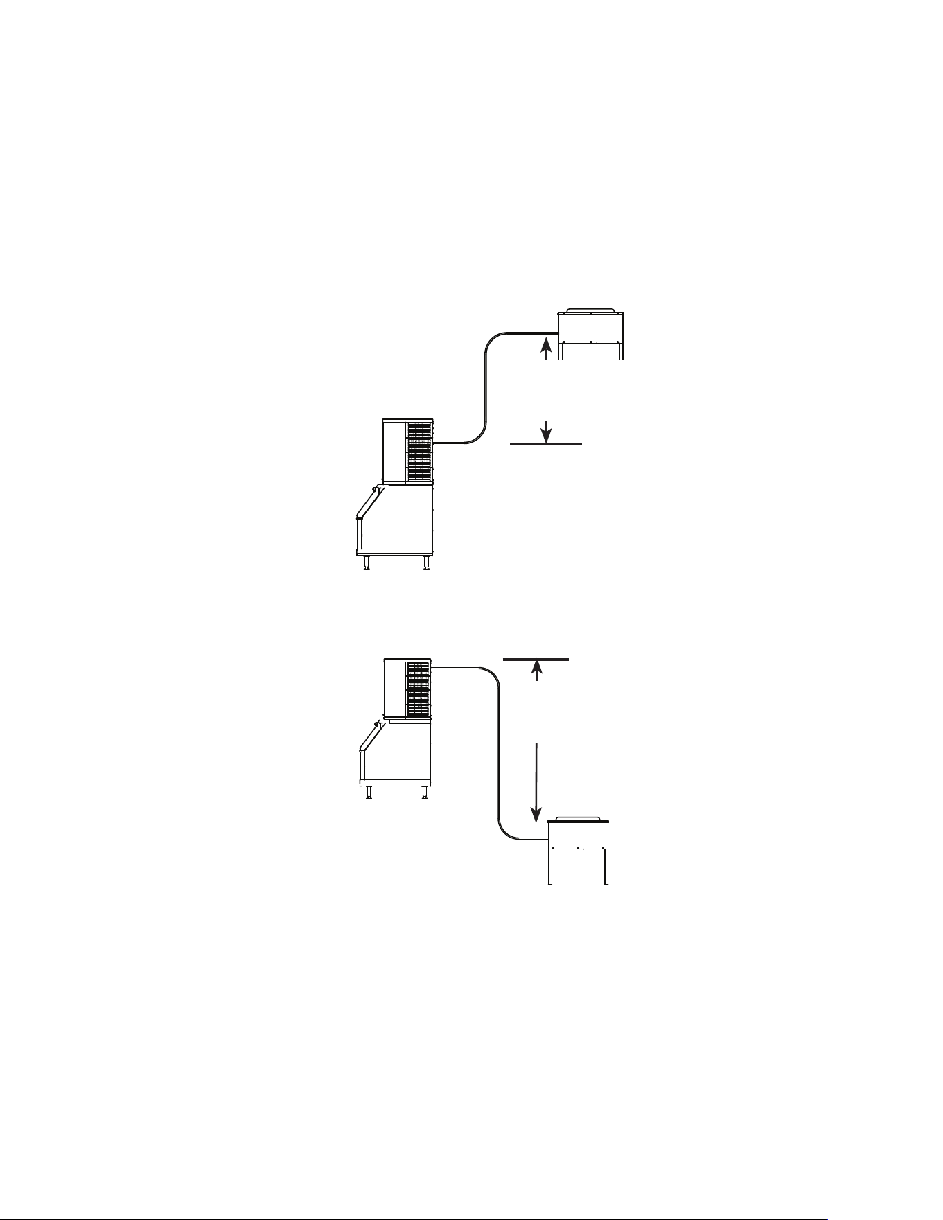
35 FT. (10.7 M)
MAXIMUM
DISTANCE
35 ft. (10.7 m) Rise: The maximum distance the Condenser
or Condensing Unit can be above the ice machine.
15 FT. (4.5 M)
MAXIMUM
DISTANCE
15 ft. (4.5 m) Drop: The maximum distance the Condenser
or Condensing Unit can be below the ice machine.

36 - Modular Part Number 000018624 Rev 00 4/26
Calculated Line Set Distance
The maximum calculated distance is 150' (45.7 m).
Line set rises, drops, horizontal runs (or combinations
of these) in excess of the stated maximums will exceed
compressor start-up and design limits. This will cause poor
oil return to the compressor.
Make the following calculations to make sure the line set
layout is within specifications.
1. Insert the measured rise into the formula below.
Multiply by 1.7 to get the calculated rise.
(Example: A condenser located 10 feet above the ice
machine has a calculated rise of 17 feet.)
2. Insert the measured drop into the formula below.
Multiply by 6.6 to get the calculated drop.
(Example. A condenser located 10 feet below the ice
machine has a calculated drop of 66 feet.)
3. Insert the measured horizontal distance into the
formula below. No calculation is necessary.
4. Add together the calculated rise, calculated drop,
and horizontal distance to get the total calculated
distance. If this total exceeds 150' (45.7 m), move
the condenser to a new location and perform the
calculations again.
Part Number 000018624 Rev 00 4/26 Modular - 37
Maximum Line Set Distance Formula
Step 1
Measured Rise ____ X 1.7 = ______Calculated Rise
(35 ft. Max)
Step 2
Measured Drop ____ X 6.6 = ______Calculated Drop
(15 ft. Max.)
Step 3
Measured Horizontal Distance = _________Horizontal
(100 ft. Max.) Distance
Step 4
Total Calculated Distance = ________Total Calculated
(150 ft. Max.) Distance
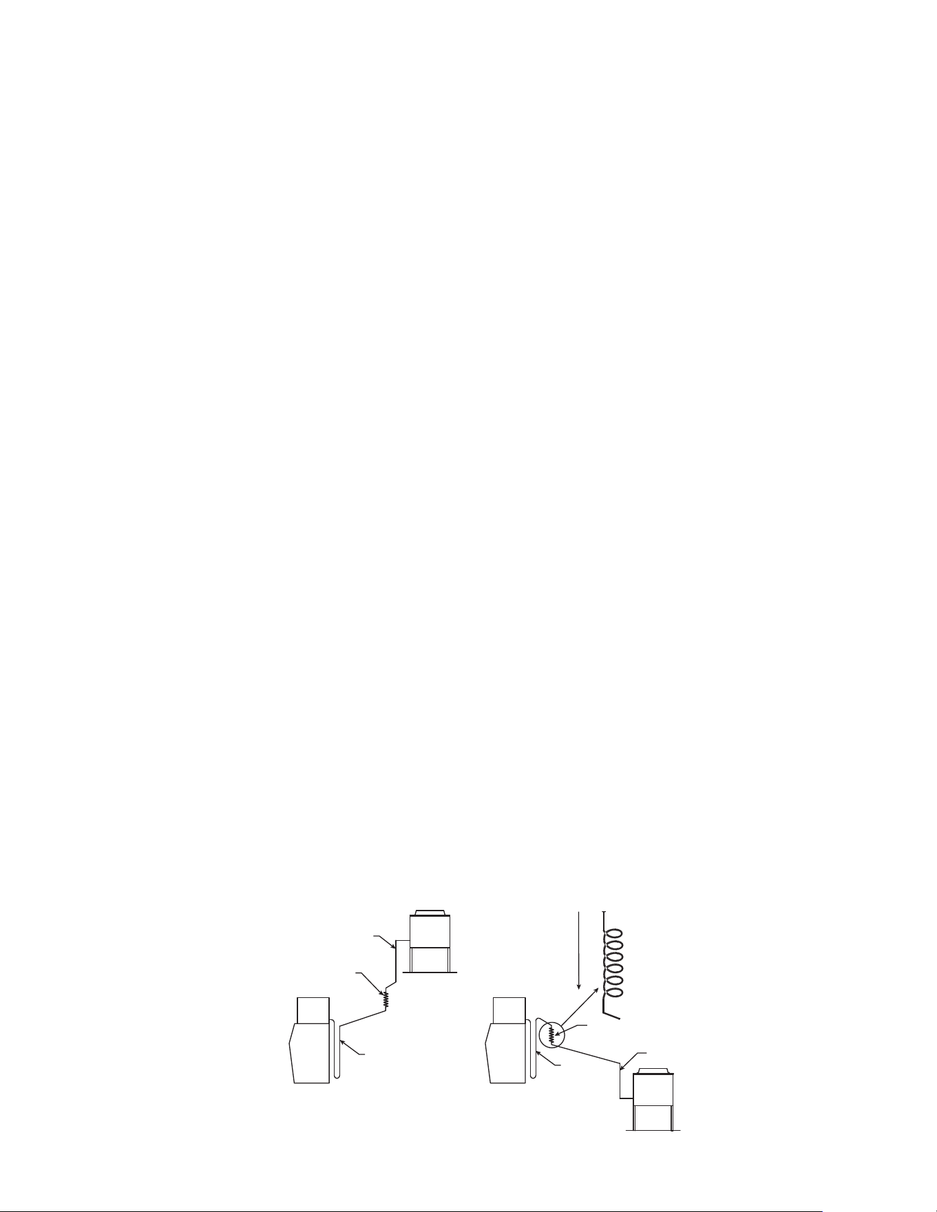
Follow these guidelines when routing the refrigerant lines.
This will help ensure proper performance and service
accessibility.
1. Optional - Make the service loop in the line sets (as
shown in Routing Line Sets graphic). This permits easy
access to the ice machine for cleaning and service. Do
not use hard rigid copper at this location.
2. Required - Do not form traps in the refrigeration lines
(except the service loop). Refrigerant oil must be free
to drain toward the ice machine or the condenser.
Route excess tubing in a supported downward
horizontal spiral (as shown below). Do not coil tubing
vertically.
3. Required - Keep outdoor refrigerant line runs as short
as possible.
1
2
3
1
2
3
Do n ar
oriontal
Spiral

THIS PAGE INTENTIONALLY LEFT BLANK
38 - Modular Part Number 000018624 Rev 00 4/26
Part Number 000018624 Rev 00 4/26 Modular - 39
De-scaling and Sanitizing
GENERAL
Sanitizing for Exterior, Remedial, and Detailed procedures
can be performed independently and more frequently
than de-scaling when needed.
De-scale and sanitize the ice machine every six months
for efficient operation. If the ice machine requires more
frequent de-scaling and sanitizing, consult a qualified
service company to test the water quality and recommend
appropriate water treatment. An extremely dirty ice
machine must be taken apart for de-scaling and sanitizing.
Manitowoc Ice Machine De-scaler and Sanitizer are
the only products approved for use in Manitowoc ice
machines.
Using non Manitowoc de-scalers, sanitizers, cleaners or
solutions may result in bodily harm and/or cause damage
to the ice machine that is not covered under the warranty.
The ice machine must be taken apart for de-scaling and
sanitizing.
Maintenance procedures are not covered by the warranty.
,
Caution
Use only Manitowoc Ice Machine De-scaler (part
number 9405463) and Sanitizer (part number
9405653). Do not mix De-scaler and Sanitizer solutions
together. It is a violation of Federal law to use these
solutions in a manner inconsistent with their labeling.
Read and understand all labels printed on bottles
before use.
Maintenance

40 - Modular Part Number 000018624 Rev 00 4/26
ICE MACHINE INSPECTION
Check all water fittings and lines for leaks. Also, confirm
refrigeration tubing is not rubbing or vibrating against
other tubing, panels, etc.
Do not put anything (boxes, etc.) in front of the ice
machine. There must be adequate airflow through and
around the ice machine to maximize ice production and
ensure long component life.
EXTERIOR CLEANING
Clean the area around the ice machine as often as
necessary to maintain cleanliness and efficient operation.
Wipe surfaces with a damp cloth rinsed in water to remove
dust and dirt from the outside of the ice machine. If a greasy
residue persists, use a damp cloth rinsed in a mild dish soap
and water solution. Wipe dry with a clean, soft cloth.
Products containing abrasives will damage the coating and
scratch the panels.
• Never use steel wool or abrasive pads for cleaning.
• Never use chlorinated, citrus based or abrasive
cleaners on exterior panels and plastic trim pieces.
REMEDIAL DESCALING
• This procedure de-scales all components in the water
flow path, and is used between the bi-yearly detailed
de-scaling and sanitizing procedure.
DETAILED DESCALING/SANITIZING
This procedure must be performed a minimum of once
every six months.
• The ice machine and bin must be disassembled de-
scaled and sanitized.
• All ice produced during the de-scaling and sanitizing
procedures must be discarded.

Part Number 000018624 Rev 00 4/26 Modular - 41
DETAILED DESCALING AND SANITIZING PROCEDURE
Ice machine de-scaler is used to remove lime scale and
mineral deposits. Ice machine sanitizer disinfects and
removes algae and slime.
TOGGLE SWITCH OPERATION
Moving the toggle switch to clean will start a Clean cycle.
• Setting the ice machine to stop after the clean cycle:
Place the toggle switch in the clean position. The ice
machine will stop after the clean cycle.
• Pausing the cleaning cycle: Move the toggle switch to
Off. Moving the toggle switch to clean will restart the
clean cycle.
• Setting the ice machine to start ice making after the
clean cycle: Place the toggle switch in the Ice position
more than 2 minutes into the clean cycle.
Step 1 Remove the front door to access the evaporator
compartment. Ice must not be on the evaporator during
the clean/sanitize cycle. Set the toggle switch to the OFF
position after ice falls from the evaporator at the end of a
harvest cycle. Or, set the switch to OFF and allow the ice to
melt off the evaporator.
,
Caution
Never use anything to force ice from the evaporator.
Damage may result.
Step 2 Remove all ice from the bin/dispenser.
n
Warning
Wear rubber gloves and safety goggles (and/or face
shield) when handling Ice Machine De-scaler or
Sanitizer.
42 - Modular Part Number 000018624 Rev 00 4/26
,
Caution
Do not mix Ice Machine De-scaler and Sanitizer
solutions together. It is a violation of Federal law to
use these solutions in a manner inconsistent with their
labeling.
Step 3 Place the toggle switch in the CLEAN position.
Water will flow through the water dump valve and down
the drain. Wait until the water trough refills, then add the
proper amount of ice machine de-scaler.
Model Amount of De-scaler
K0300 K0400 K0420 K0500
K0600 K0700 K1000
5 ounces (150 ml)
K1350 K1700 K1800 9 ounces (265 ml)
Step 4 Wait until the cycle is complete (approximately
24-30 minutes) then place the toggle switch in the off
position and disconnect power and water supplies to the
ice machine (and dispenser when used).
Warning
Disconnect the electric power to the ice machine at
the electric service switch box.
Step 5 Remove parts for de-scaling.
Refer to the proper parts removal for your machine.
Continue with Step 6 when the parts have been removed.
Part Number 000018624 Rev 00 4/26 Modular - 43
Step 6 Mix a solution of de-scaler and lukewarm water.
Depending on the amount of mineral buildup, a larger
quantity of solution may be required. Use the ratio in the
table below to mix enough solution to thoroughly de-scale
all parts.
Solution Type Water Mixed with
De-scaler 1 gal. (4 l) 16 oz (500 ml) de-scaler
Step 7 Use half of the de-scaler & water solution to
de-scale all components. The solution will foam when it
contacts lime scale and mineral deposits; once the foaming
stops use a soft bristle brush, sponge or cloth (not a wire
brush) to carefully de-scale the parts. Soak the parts for
5 minutes (15 – 20 minutes for heavily scaled parts). Rinse
all components with clean water.
Step 8 While components are soaking, use half of the
de-scaler & water solution to clean all foodzone surfaces
of the ice machine and bin/dispenser. Use a nylon brush or
cloth to thoroughly clean the following ice machine areas:
• Evaporator plastic parts – including top, bottom and
sides
• Bin bottom, sides and top
Rinse all areas thoroughly with clean water.
44 - Modular Part Number 000018624 Rev 00 4/26
SANITIZING PROCEDURE
Step 9 Mix a solution of sanitizer and warm water.
Solution Type Water Mixed With
Sanitizer 3 gal. (12 l) 2 oz (60 ml) sanitizer
Step 10 Use half of the sanitizer/water solution to
sanitize all removed components. Use a spray bottle to
liberally apply the solution to all surfaces of the removed
parts or soak the removed parts in the sanitizer/water
solution. Do not rinse parts after sanitizing.
Step 11 Use half of the sanitizer/water solution to
sanitize all foodzone surfaces of the ice machine and bin.
Use a spray bottle to liberally apply the solution. When
sanitizing, pay particular attention to the following areas:
• Evaporator plastic parts - including top, bottom and
sides
• Ice machine base (top of bin) and area above the
water trough
• Bin bottom, sides and top
Do not rinse the sanitized areas.
Step 12 Replace all removed components.
Step 13 Wait 20 minutes.
Step 14 Reapply power to the ice machine and place the
toggle switch in the CLEAN position.
Part Number 000018624 Rev 00 4/26 Modular - 45
Step 15 Water will flow through the water dump valve
and down the drain. Wait until the water trough refills,
then add the proper amount of ice machine sanitizer to
the water trough.
Model Amount of Sanitizer
K0300 K0400 K0420 K0500
K0600 K0700 K1000
3 ounces (90 ml)
K1350 K1700 K1800 6 ounces (180 ml)
Step 16 After the sanitize cycle is complete
(approximately 24 minutes) move the toggle switch to the
ICE position to start ice making.
Notice
Electrical connector must never be exposed to any
liquids.

46 - Modular Part Number 000018624 Rev 00 4/26
REMOVE PARTS FOR DESCALING/SANITIZING
n
Warning
Disconnect electric power to the ice machine at the
electric switch box before proceeding.
1. Remove the water curtain
• Gently flex the curtain in the center and remove it
from the right side.
• Slide the left pin out.
2. Remove the water trough and water diverter from the
bottom of the evaporator.
• Depress tabs on right and left side of the water
trough.
• Allow front of water trough to drop as you pull
forward to disengage the rear pins.
• Loosen thumbscrew on left side of water diverter
tray.
3. Remove the ice thickness and harvest float switches
• Pull the float switch straight down to disengage.
• Lower the float switch until the wiring connector
is visible.
• Disconnect the wire lead from the float switch.
• Remove the float switch from the ice machine.

Part Number 000018624 Rev 00 4/26 Modular - 47
4. Remove the water distribution tube
NOTE: Distribution tube thumbscrews are retained
to prevent loss. Loosen thumbscrews but do not pull
thumbscrews out of distribution tube.
• Loosen the two outer screws (do not remove
screws completely they are retained to prevent
loss) and pull forward on the distribution tube to
release from slip joint.
• Disassemble distribution tube by loosening
the two middle thumbscrews and dividing the
distribution tube into two pieces.
• Proceed to page 43 Step 6.
5. Remove the Water Trough
• Depress tabs on right and left side of the water
trough.
• Allow front of water trough to drop as you pull
forward to disengage the rear pins.
• Remove the water trough from the bin area.

48 - Modular Part Number 000018624 Rev 00 4/26
Remedial De-scaling Procedure
This procedure de-scales all components in the water flow
path, and is used to de-scale the ice machine between the
bi-yearly detailed de-scaling and sanitizing procedure.
Ice machine de-scaler is used to remove lime scale and
mineral deposits. Ice machine sanitizer disinfects and
removes algae and slime.
Step 1 Ice must not be on the evaporator during the
clean/sanitize cycle. Follow one of the methods below:
• Move the toggle switch to the OFF position at
the end of a harvest cycle after ice falls from the
evaporator.
• Move the toggle switch to the OFF position and
allow the ice to melt.
,
Caution
Never use anything to force ice from the evaporator.
Damage may result.
n
Warning
Wear rubber gloves and safety goggles (and/or face
shield) when handling Ice Machine De-scaler or
Sanitizer.
Part Number 000018624 Rev 00 4/26 Modular - 49
Step 2 Open the front door and move the toggle
switch to the CLEAN position. Wait until the water trough
refills (approximately 1 minute) and then add the proper
amount of Ice Machine Descaler to the water trough.
Model Amount of De-scaler
K0300 K0400 K0420 K0500
K0600 K0700 K1000
5 ounces (150 ml)
K1350 K1700 K1800 9 ounces (265 ml)
Step 3 After 1 minute place the toggle switch in the
ICE position and close and secure the front door. The ice
machine will automatically start ice making after the Clean
cycle is complete (approximately 24 minutes).
Door Removal
1. Use a Phillips screwdriver to loosen the two screws
securing the door. Do not remove, they are retained
to prevent loss.
2. Tilt door forward and lift up to remove.
50 - Modular Part Number 000018624 Rev 00 4/26
Cleaning the Air Filter & AirCondenser
n
Warning
Disconnect electric power to the ice machine head
section and the remote condensing unit at the electric
service switches before cleaning the condenser.
The washable filter on self-contained ice machines is
designed to catch dust, dirt, lint and grease. Clean the filter
once a month with mild soap and water.
A dirty condenser restricts airflow, resulting in excessively
high operating temperatures. This reduces ice production
and shortens component life.
n
Warning
The condenser fins are sharp. Use care when cleaning
them.
• Clean the condenser at least every six months.
• Shine a flashlight through the condenser to check for
dirt between the fins.
• Blow compressed air or rinse with water from the
inside out (opposite direction of airflow).
• If dirt still remains, call a service agent to clean the
condenser.

Part Number 000018624 Rev 00 4/26 Modular - 51
Removal from Service/Winterization
AIRCOOLED MODELS
1. Turn off the ice machine by pressing the On/Off
button.
2. Turn off the water supply.
3. Remove the water from the water trough.
4. Disconnect and drain the incoming ice-making water
line at the rear of the ice machine.
5. Energize the ice machine and wait one minute for the
water inlet valve to open - or - Energize all relays in
the touchscreen service menu.
6. Blow compressed air in both the incoming water and
the drain openings in the rear of the ice machine until
no more water comes out of the water inlet lines or
the drain.
7. Disconnect the electric power at the circuit breaker or
the electric service switch.
8. Make sure water is not trapped in any of the water
lines, drain lines, distribution tubes, etc.
9. Replace all panels.
WATERCOOLED MODELS
1. Perform Steps 1 – 6 under “Air-Cooled Models.”
2. Disconnect the incoming water and drain line from
the water-cooled condenser.
3. Start the ice making cycle by pressing the On/Off
button and wait for the freeze cycle. The increasing
refrigerant pressure will open the water regulating
valve.
4. Blow compressed air through the condenser until no
water remains.
5. Turn off ice machine by pressing the On/Off button
and then disconnecting power to the ice machine.
6. Replace all panels.

THIS PAGE INTENTIONALLY LEFT BLANK
52 - Modular Part Number 000018624 Rev 00 4/25

Part Number 000018624 Rev 00 4/26 Modular - 53
Ice Making Sequence of Operation
NOTE: The toggle switch must be in the ICE position and
the water curtain must be closed before the ice machine
will start.
Water Purge Cycle
The ice machine purges any remaining water from the
water trough down the drain and the refrigeration
compressor starts and the refrigeration compressor starts.
Freeze Cycle
Prechill - The refrigeration system chills the evaporator
before water flow over the evaporator starts. The water
inlet valve energizes during the pre-chill and remains on
until the ice thickness float switch is satisfied.
Freeze - Water flowing across the evaporator freezes
and builds ice on the evaporator. After a sheet of ice has
formed, the Harvest float switch signals the control board
to start a harvest cycle.
Dump Cycle
Upon initial start-up or start-up after an auto shut-off,
water flows through the water dump valve and down the
drain. If the water trough fails to drain after the water
dump valve has energized/
de-energized, a clean light will flash.
Harvest Cycle
Any remaining water is purged down the drain as
refrigerant gas warms the evaporator. When the
evaporator warms, the sheet of cubes slides off the
evaporator and into the storage bin. If all cubes fall clear
of the water curtain, the ice machine starts another freeze
cycle.
Operation

54 - Modular Part Number 000018624 Rev 00 4/26
Full Bin Cycle
If the water curtain is held open by ice cubes, the ice
machine shuts off and starts a 3-minute delay period.
When the water curtain closes, the ice machine starts a
new cycle at the water purge, provided the 3-minute delay
period has expired.
CONTROL BOARD TIMERS
• The ice machine is locked into the freeze cycle for
6 minutes before a harvest cycle can be initiated.
• The freeze time lock in feature is bypassed on the
initial cycle (manual start or after a full bin/safety limit
condition).
• If the harvest float switch is in the down position for
10 continuous seconds during the start of an initial
freeze cycle, a harvest sequence is initiated. If the
harvest float is in the down position in subsequent
cycles a safety limit 3 cycle is initiated.
• The maximum freeze time is 35 minutes (60 minutes
prior to software revision 3.2) at which time the
control board automatically initiates a harvest
sequence.
• The maximum harvest time is 3.5 minutes (software
revision 3.2 and later, 7 minute max harvest, with
water assist after 3.5 minutes. SL#2 will shut down
after 100 cycles). The control board automatically
initiates a freeze sequence when these times are
exceeded.
• The ice machine will continue to fill with water for up
to six minutes, or until the high water float opens for
5 continuous seconds. The control board will energize
the water inlet valve one more time 3 minutes into the
freeze cycle.

Part Number 000018624 Rev 00 4/26 Modular - 55
SERVICE LIMITS
Service limits are stored and indicated by the control
board. The number of cycles required to stop the ice
machine varies for each service limit.
Service limits can be reset by cycling the toggle switch Off/
On and starting a new ice making cycle.
A service limit is indicated by a flashing light on the control
board.
Service Limit 1
Software revision 3.2 and later:
If the freeze time reaches 35 minutes, the control board
automatically initiates a harvest cycle.
• After 3 consecutive 35 minute cycles control board
light SL#1 light will flash on/off at 1 second intervals.
• If 6 consecutive 35-minute freeze cycles occur, the ice
machine stops and the SL#1 light on the control board
will be on continuously.
NOTE: Prior to control board software revision 3.2
the maximum freeze time is 60 minutes rather than
35 minutes.
Service Limit 2
If the harvest time reaches 3.5 minutes, the control board
automatically returns the ice machine to the freeze cycle
(software revision 3.2 and later, 7 minute max harvest,
with water assist after 3.5 minutes. SL#2 will shut down
after 3 attempts).
• If 3 consecutive 3.5 minute harvest cycles occur the
SL#2 light on the control board will flash on/off at 1
second intervals. After 75 consecutive 3.5 minutes
harvest cycles the SL#2 light will be energized
continuously.
• If 100 consecutive 3.5 minute harvest cycles occur, the
ice machine stops and the SL#2 light on the control
board will be on continuously.

56 - Modular Part Number 000018624 Rev 00 4/26
Service Limit 3
If the harvest float switch hasn’t opened for 10 continuous
seconds within 4 minutes of the water inlet valve
energizing the ice machine stops.
• Service Limit 3 is bypassed on the initial cycle (manual
start or after a full bin/safety limit condition). For
all subsequent cycles the ice machine stops for 30
minutes when the water inlet valve is energized for
4 minutes and the harvest float valve didn’t open.
Control board lights SL#1 and SL#2 will flash on/off at 1
second intervals.
• The ice machine automatically restarts at the end of
the 30 minute delay period and stops flashing the
control board lights.
• If 100 consecutive failures occur the ice machine stops
and the SL#1 & SL#2 lights flash on/off at 1 second
intervals.
• SL#1 & SL#2 will flash 3 times on startup and
automatically erase after 100 normal cycles.
Part Number 000018624 Rev 00 4/26 Modular - 57
ENERGIZED PARTS CHART
Self-Contained Ice Machines
ICE MAKING
SEQUENCE OF
OPERATION
Water Pump
Harvest
Valve
Water Inlet
Valve
Dump Valve
Compressor
& Condenser
Fan Motor*
Harvest Float
Switch
Ice Thickness
Float Switch
Length of
Time
Initial Start-up
1a. Water purge
1b. Delay period
on on off on off closed closed 45 seconds
off off off off off closed closed 5 seconds
2. Refrigeration
System Start-up
2a. Equalize
Pressure
2b. Compressor
Start-up
off on off off off closed closed 5 seconds
off on off off on closed closed 5 seconds
Freeze Sequence
3. Pre chill
off off on off on open closed
120 Seconds
initial cycle
Thereafter
30 seconds
58 - Modular Part Number 000018624 Rev 00 4/26
ICE MAKING
SEQUENCE OF
OPERATION
Water Pump
Harvest
Valve
Water Inlet
Valve
Dump Valve
Compressor
& Condenser
Fan Motor*
Harvest Float
Switch
Ice Thickness
Float Switch
Length of
Time
4. Freeze on off on off on
open then
closed
closed then
open
Until Harvest
Float Switch
closes for
10 continual
seconds
Harvest Sequence
5. Water Purge
on on off on on closed closed 45 seconds
6. Harvest off on off off on closed closed
Bin switch
activation
7. Automatic
Shut-off
off off off off off closed closed
Until bin
switch
re-closes
* Condenser Fan Motor: The fan motor is wired through a fan cycle pressure control; therefore, it may cycle on and off.
Part Number 000018624 Rev 00 4/26 Modular - 59
Operational Checks
ICE THICKNESS CHECK
After a harvest cycle, inspect the ice cubes in the ice
storage bin. The ice thickness float switch is factory-set to
maintain the ice bridge thickness at 1/8” (3 mm).
NOTE: Make sure the water curtain is in place when
performing this check. It prevents water from splashing out
of the water trough.
1. Inspect the bridge connecting the cubes. It should be
about 1/8” (3 mm) thick.
2. If adjustment is necessary make the following
adjustment as you face the machine.
NOTE: The float can be adjusted with a 3/4” wrench while
the water trough is in place.
• Turn the ice thickness float switch to the right to
increase bridge thickness
• Turn the ice thickness float switch to the left to
decrease bridge thickness.
• Test run two cycles to verify bridge thickness.
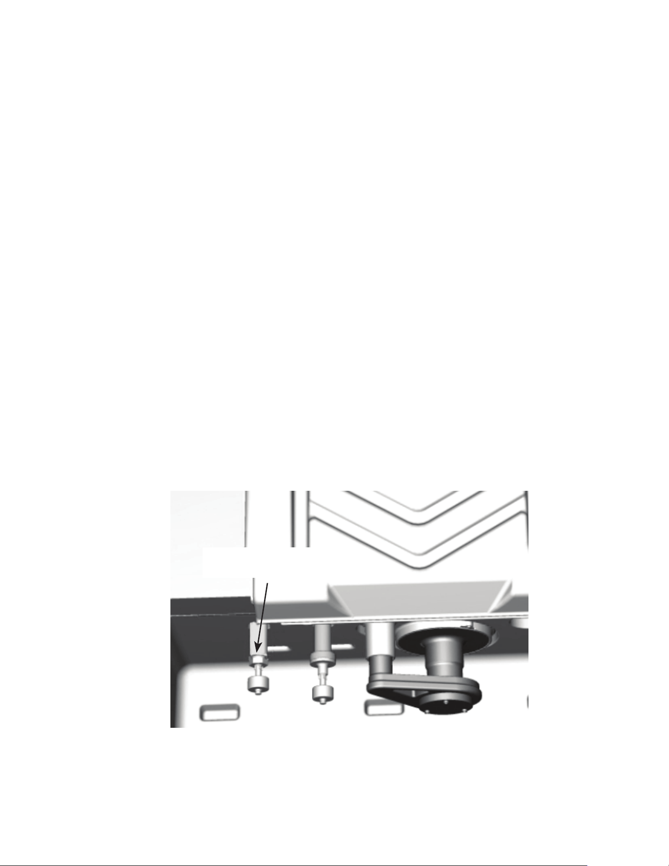
Ice Thickness Float
Switch Adjustment
60 - Modular Part Number 000018624 Rev 00 4/26
MINIMUM/MAXIMUM SLAB WEIGHTS
Adjust ice thickness to meet chart specifications.
Model
Minimum Ice Weight
Per Cycle
Maximum Ice
Weight Per Cycle
KP0300
KT0300
3.4 lbs
1542 g
3.9 lbs
1769 g
KP0400
KT0400
3.4 lbs
1542 g
3.9 lbs
1769 g
KP0420
KT0420
3.4 lbs
1542 g
3.9 lbs
1769 g
KP0500
KT0500
4.125 lbs
1871 g
4.75 lbs
2154 g
KP0700
KT0700
4.125 lbs
1871 g
4.75 lbs
2154 g
KP1000
KT1000
7.25 lbs
3288 g
7.75 lbs
3515 g
KT1700
13.2 lbs
5987 g
14.8 lbs
6713 g
Model
Minimum Ice Weight
Per Cycle
Maximum Ice
Weight Per Cycle
K0250
K0350
K0420
3.4 lbs
1542 g
3.9 lbs
1769 g
K0500
K0600
4.6 lbs
2.1 kg
5.2 lbs
2.36 kg
K1350
12.75 lbs
5.78 kg
14.75 lbs
6.69 kg
K1800
12.80
5.8 kg
14.4 lbs
6.5 kg

Part Number 000018624 Rev 00 4/26 Modular - 61
Service Limits
Service limits are stored and indicated by the control
board. The number of cycles required to stop the ice
machine varies for each service limit.
Service limits can be reset by cycling the toggle switch Off/
On and starting a new ice making cycle.
A service limit is indicated by a flashing light on the control
board.
Service Limit 1
Software revision 3.2 and later:
If the freeze time reaches 35 minutes, the control board
automatically initiates a harvest cycle.
• After 3 consecutive 35 minute cycles control board
light SL#1 light will flash on/off at 1 second intervals.
• If 6 consecutive 35-minute freeze cycles occur, the ice
machine stops and the SL#1 light on the control board
will be on continuously.
NOTE: Prior to control board software revision 3.2
the maximum freeze time is 60 minutes rather than
35 minutes.
Service Limit 2
Software revision 3.2 and later:
If the harvest time reaches 7 minutes, the control board
automatically returns the ice machine to the freeze cycle.
• If 3 consecutive 7 minute harvest cycles occur the SL#2
light on the control board will flash on/off at 1 second
intervals. After 100 consecutive 7 minute harvest
cycles the SL#2 light will be energized continuously.
• If 100 consecutive 3.5 minute harvest cycles occur, the
ice machine stops and the SL#2 light on the control
board will be on continuously.
Troubleshooting

62 - Modular Part Number 000018624 Rev 00 4/26
Software revision 3.1 and before:
If the harvest time reaches 3.5 minutes, the control board
automatically returns the ice machine to the freeze cycle
(software revision 3.2 and later, 7 minute max harvest,
with water assist after 3.5 minutes. SL#2 will shut down
after 3 attempts).
• If 3 consecutive 3.5 minute harvest cycles occur the
SL#2 light on the control board will flash on/off at 1
second intervals. After 75 consecutive 3.5 minutes
harvest cycles the SL#2 light will be energized
continuously.
• If 100 consecutive 3.5 minute harvest cycles occur, the
ice machine stops and the SL#2 light on the control
board will be on continuously.

Part Number 000018624 Rev 00 4/26 Modular - 63
Service Limit 3
If the harvest float switch hasn’t opened for 10 continuous
seconds within 4 minutes of the water inlet valve
energizing the ice machine stops.
• Service Limit 3 is bypassed on the initial cycle (manual
start or after a full bin/safety limit condition). For
all subsequent cycles the ice machine stops for 30
minutes when the water inlet valve is energized for
4 minutes and the harvest float valve didn’t open.
Control board lights SL#1 and SL#2 will flash on/off at 1
second intervals.
• The ice machine automatically restarts at the end of
the 30 minute delay period and stops flashing the
control board lights.
• If 100 consecutive failures occur the ice machine stops
and the SL#1 & SL#2 lights flash on/off at 1 second
intervals.
• SL#1 & SL#2 will flash 3 times on startup and
automatically erase after 100 normal cycles.

64 - Modular Part Number 000018624 Rev 00 4/26
Determining Which Service Limit Stopped the Ice
Machine:
1. Cycle the toggle switch Off.
2. Cycle the toggle switch On to start ice making.
3. Watch the service limit lights.
• One will flash corresponding to service limits 1
or 2.
4. Service limit 3 is indicated by both SL#1 & SL#2
flashing.
After service limit indication, the ice machine will restart
and run until a service limit is exceeded again.
Service Limit Notes
• A continuous run of 100 harvests automatically erases
the service limit code.
• The control board will store and indicate only one
service limit – the last one exceeded.
• If the toggle switch is cycled OFF and then ON prior to
reaching the 100-harvest point, the last service limit
exceeded will be indicated.

Part Number 000018624 Rev 00 4/26 Modular - 65
SERVICE LIMIT CHECKLIST
The following checklists are designed to assist the service
technician in analysis. However, because there are many
possible external problems, do not limit your diagnosis to
only the items listed.
Service Limit #1
Control board software revision 3.2 and higher
Freeze time exceeds 35 minutes for 6 consecutive freeze
cycles.
Possible Cause Checklist
Improper installation
• Refer to “Installation/Visual Inspection Checklist” on
page 84
Water System
• Float switch or water escaping water trough
• Low water pressure (20 psig min.)
• High water pressure (80 psig max.)
• High water temperature (90°F/32.2°C max.)
• Clogged water distribution tube
• Dirty/defective water inlet valve
• Defective water pump

66 - Modular Part Number 000018624 Rev 00 4/26
Electrical System
• Harvest cycle not initiated electrically
• Contactor not energizing
• Compressor electrically non-operational
• Restricted condenser air flow
• High inlet air temperature (110°F/43.3°C max.)
• Condenser discharge air re-circulation
• Dirty condenser fins
• Defective fan cycling control
• Defective fan motor
• Dirty condenser
NOTE: Prior to control board software revision 3.2
the maximum freeze time is 60 minutes rather than
35 minutes.
Refrigeration System
• Non-OEM components
• Improper refrigerant charge
• Defective compressor
• TXV starving or flooding (check bulb mounting)
• Non-condensible in refrigeration system
• Plugged or restricted high side refrigerant lines or
component
• Defective harvest valve

Part Number 000018624 Rev 00 4/26 Modular - 67
Service Limit #2
Harvest time exceeds 7 minutes for 100 Consecutive
harvest cycles.
Possible Cause Checklist
Improper installation
• Refer to “Installation/Visual Inspection Checklist” on
page 84
Water System
• Water area (evaporator) dirty
• Dirty/defective water dump valve
• Vent tube not installed on water outlet drain
• Water freezing behind evaporator
• Plastic extrusions and gaskets not securely mounted to
the evaporator
Electrical System
• Bin switch defective
• Premature harvest
Refrigeration System
• Non-OEM components
• Improper refrigerant charge
• Defective harvest valve
• TXV flooding (check bulb mounting)
• Defective fan cycling control

68 - Modular Part Number 000018624 Rev 00 4/26
Service Limit 3
The harvest float switch hasn’t opened for 10 continuous
seconds in the first 4 minutes of the freeze cycle.
Possible Cause Checklist
Improper installation
• Refer to “Installation/Visual Inspection Checklist” on
page 84
Water System
• Water dump valve
• Harvest float valve dirty or defective
• Low water pressure (20 psig min.)
• Dirty defective water filter (when used)
• Loss of water from sump area
• Dirty/defective water inlet valve
Electrical System
• Water inlet valve coil defective
• Harvest float valve defective

Part Number 000018624 Rev 00 4/26 Modular - 69
Control Board Test Mode
NOTE: The water curtain/bin switch can be open or closed
and does not affect the operation of the test mode.
To enter the test mode, move the toggle switch to off,
then press and hold the test button on the control board
for 3 seconds. The control board test mode performs the
following functions for a 2-minute time period:
• Energizes all control board relays
• Energizes all control board lights
After 2 minutes, the control board will automatically
initiate and complete one ice-making cycle, then stop (On
software revision 2.70 or earlier). On software version 2.71
or later the control board will complete 500 ice making
cycles and shutdown.
Canceling a test cycle:
To cancel a test cycle, press the test button a second time.
Restarting a test cycle:
The test cycle will restart each time the test button is
pressed for a 3-second time period.

70 - Modular Part Number 000018624 Rev 00 4/26
Diagnosing an Ice Machine that Will Not Run
n
Warning
High (line) voltage is applied to the control board at
all times. Removing the control board fuse or pressing
the power button will not remove the power supplied
to the control board.
1. Verify primary voltage is supplied to ice machine and
the fuse/circuit breaker is closed.
2. Verify control board fuse is okay.
NOTE: If any control board lights are on, the fuse is okay.
3. Verify the bin switch functions properly. A defective
bin switch can falsely indicate a full bin of ice.
4. Verify toggle switch functions properly. A defective
toggle switch may keep the ice machine in the OFF
mode. Refer to toggle switch diagnostics when Steps
1 – 3 test good.
5. Be sure Steps 1 – 4 were followed thoroughly.
Intermittent problems are not usually related to the
control board. Replace control board if toggle switch
operation is correct.

Part Number 000018624 Rev 00 4/26 Modular - 71
Troubleshooting By Symptom
The troubleshooting procedures follow diagnostic charts.
There are four symptoms, the symptom that you are
experiencing will determine which diagnostic chart to
use. The chart asks yes and no questions to determine
the problem. The diagnostic chart will direct you to a
procedure to correct the problem. Remote condenser, and
self contained models use separate charts.
SYMPTOM #1
Ice Machine Stops Running
Ice machine is in Ice Making cycle
or
Has a History of Shutting Down
• Refer to Ice Machine Stops Running diagnostic chart
SYMPTOM #2
Ice Machine has a Long Freeze Cycle
Ice Formation is Thick
or
Thin Ice Fill on Inlet or Outlet of Evaporator
or
Low Production
Service Fault (possible)
• Refer to Freeze Cycle Refrigeration System Operational
Analysis Table
SYMPTOM #3
Ice Machine Will Not Harvest - Freeze Cycle is Normal and
Ice Cubes are Not Melted After Harvest
Long Harvest (possible)
• Refer to Refrigeration Harvest Flow Chart
SYMPTOM #4
Ice Machine Will Not Harvest - Freeze Cycle is Normal and
Ice Cubes are Melted After Harvest
• Refer to Ice Meltout Flow Chart
72 - Modular Part Number 000018624 Rev 00 4/26
SYMPTOM #1 SELFCONTAINED AIR, WATERCOOLED
TRADITIONAL REMOTE
Ice Machine stops running or has history of shutting down
NO
NO
YES
NO
YES
YES
Control board has
energized lights?
Does Ice Machine run in Clean?
Ice Machine starts when Toggle
Switch is moved to ICE?
Refer to “Diagnosing an Ice
Machine that Will Not Run”
Part Number 000018624 Rev 00 4/26 Modular - 73
NO
YES
YES
Which light flashed
Immediately aer reseng
the toggle switch?
Refer to Safety Limit #1
Long Freeze Cycle
Refer to Safety Limit #2
Long Harvest Cycle
Refer to Safety Limit #3
No Water/Water Loss
Is the Water Curtain magnet
aached?
Refer to Bin Switch
Diagnoscs
Run machine & check for
Normal Operaon
Replace The Water Curtain
Install Water Curtain
SL1 LED
Flash (Once)
SL2 LED
Flash (Twice)
SL3 (SL1 & SL2 LED’s)
Flash (3 mes)
NO
YES
Is the Water Curtain
in place?

74 - Modular Part Number 000018624 Rev 00 4/26
#2 LOW PRODUCTION, LONG FREEZE CYCLE
Ice Machine has a Long Freeze Cycle
Ice Formation is Thick
or
Thin on Inlet or Outlet of Evaporator
or
Low Production
How to Use the Freeze Cycle Refrigeration System
Operational Analysis Table
GENERAL
These tables must be used with charts, checklists and
other references to eliminate refrigeration components
not listed on the tables and external items and problems
which can cause good refrigeration components to appear
defective.
The tables list five different defects that may affect the ice
machine’s operation.
NOTE: A low-on-charge ice machine and a starving
expansion valve have very similar characteristics and are
listed under the same column.
NOTE: Before starting, see “Before Beginning Service” for
a few questions to ask when talking to the ice machine
owner.
PROCEDURE
Step 1 Complete the “Operation Analysis” column.
Read down the left “Operational Analysis” column.
Perform all procedures and check all information listed.
Each item in this column has supporting reference material
to help analyze each step.
While analyzing each item separately, you may find an
“external problem” causing a good refrigerant component
to appear bad. Correct problems as they are found. If
the operational problem is found, it is not necessary to
complete the remaining procedures.

Part Number 000018624 Rev 00 4/26 Modular - 75
Step 2 Enter Checkmarks ().
Each time the actual findings of an item in the
“Operational Analysis” column matches the published
findings on the table, enter a Checkmark.
Example: Freeze cycle suction pressure is determined to be
low. Enter a Checkmark in the “low” column.
Step 3 Add the Checkmarks listed under each of
the four columns. Note the column number
with the highest total and proceed to “Final
Analysis.”
NOTE: If two columns have matching high numbers,
a procedure was not performed properly, supporting
material was not analyzed correctly or the problem
component is not covered by the analysis table.
Before Beginning Service
Ice machines may experience operational problems
only during certain times of the day or night. A machine
may function properly while it is being serviced, but
malfunctions later. Information provided by the user can
help the technician start in the right direction, and may be
a determining factor in the final diagnosis.
Ask these questions before beginning service:
• When does the ice machine malfunction? (night, day,
all the time, only during the Freeze cycle, etc.)
• When do you notice low ice production? (one day a
week, every day, on weekends, etc.)
• Can you describe exactly what the ice machine seems
to be doing?
• Has anyone been working on the ice machine?
• During “store shutdown,” is the circuit breaker, water
supply or air temperature altered?
• Is there any reason why incoming water pressure
might rise or drop substantially?
76 - Modular Part Number 000018624 Rev 00 4/26
SYMPTOM #2 REFRIGERATION COMPONENT DIAGNOSTIC CHART
Operational Analysis 1 2 3 4
Ice Production Published 24 hour ice production________________
Calculated (actual) 24 hour ice production_______________
NOTE: The ice machine is operating properly if the ice fill pattern is normal and ice production is within
10% of charted capacity.
Installation and Water
System
All installation and water related problems must be corrected
before proceeding with chart.
Part Number 000018624 Rev 00 4/26 Modular - 77
Operational Analysis 1 2 3 4
Ice Formation Pattern Ice formation is
extremely thin on outlet
of evaporator
-or-
No ice formation on
entire evaporator
Ice formation extremely
thin on outlet of
evaporator
-or-
No ice formation on
entire evaporator
Ice formation is normal
-or-
Ice formation is
extremely thin on the
bottom of evaporator
-or-
No ice formation on
evaporator
Ice formation is normal
-or-
No ice formation on
entire evaporator
Service Limits
Refer to “Analyzing Service
Limits” to eliminate all non-
refrigeration problems.
Stops on service limit:
1 or 2
Stops on service limit:
1
Stops on service limit:
1 or 2
Stops on service limit:
1
78 - Modular Part Number 000018624 Rev 00 4/26
Operational Analysis 1 2 3 4
Freeze Cycle
Discharge Pressure
________ ______ ______
1 minute Middle End
If discharge pressure is High or Low, refer to freeze cycle high or low discharge pressure problem checklist
to eliminate problems and/or components not listed on this table before proceeding.
Freeze Cycle Suction Pressure
________ ______ ______
1 minute Middle End
If suction pressure is High or Low refer to freeze cycle high or low suction pressure problem checklist to
eliminate problems and/or components not listed on this table before proceeding.
Suction pressure is
High
Suction pressure is
Low
Suction pressure is
High
Suction pressure is
High
Part Number 000018624 Rev 00 4/26 Modular - 79
Operational Analysis 1 2 3 4
Harvest Valve
The harvest valve
inlet is
HOT
and
The compressor
discharge line is
HOT
The harvest valve
inlet is
COOL
and
The compressor
discharge line is
HOT
The harvest valve
inlet is
COOL
and
The compressor
discharge line is
COOL
The harvest valve
inlet is
COOL
and
The compressor
discharge line is
HOT
Discharge Line Temp.
Record freeze cycle discharge
line temp at the end of freeze
cycle.
Discharge line temp
150°F (66°C) or higher at
the end of freeze cycle
Discharge line temp
150°F (66°C) or higher at
the end of freeze cycle
Discharge line temp
less than 150°F (66°C) at
the end of freeze cycle
Discharge line temp
150°F (66°C) or higher at
the end of freeze cycle
Final Analysis
Enter total number of boxes
checked in each column.
Harvest Valve
Leaking
Low On Charge
-or-
TXV Starving
TXV Flooding Compressor
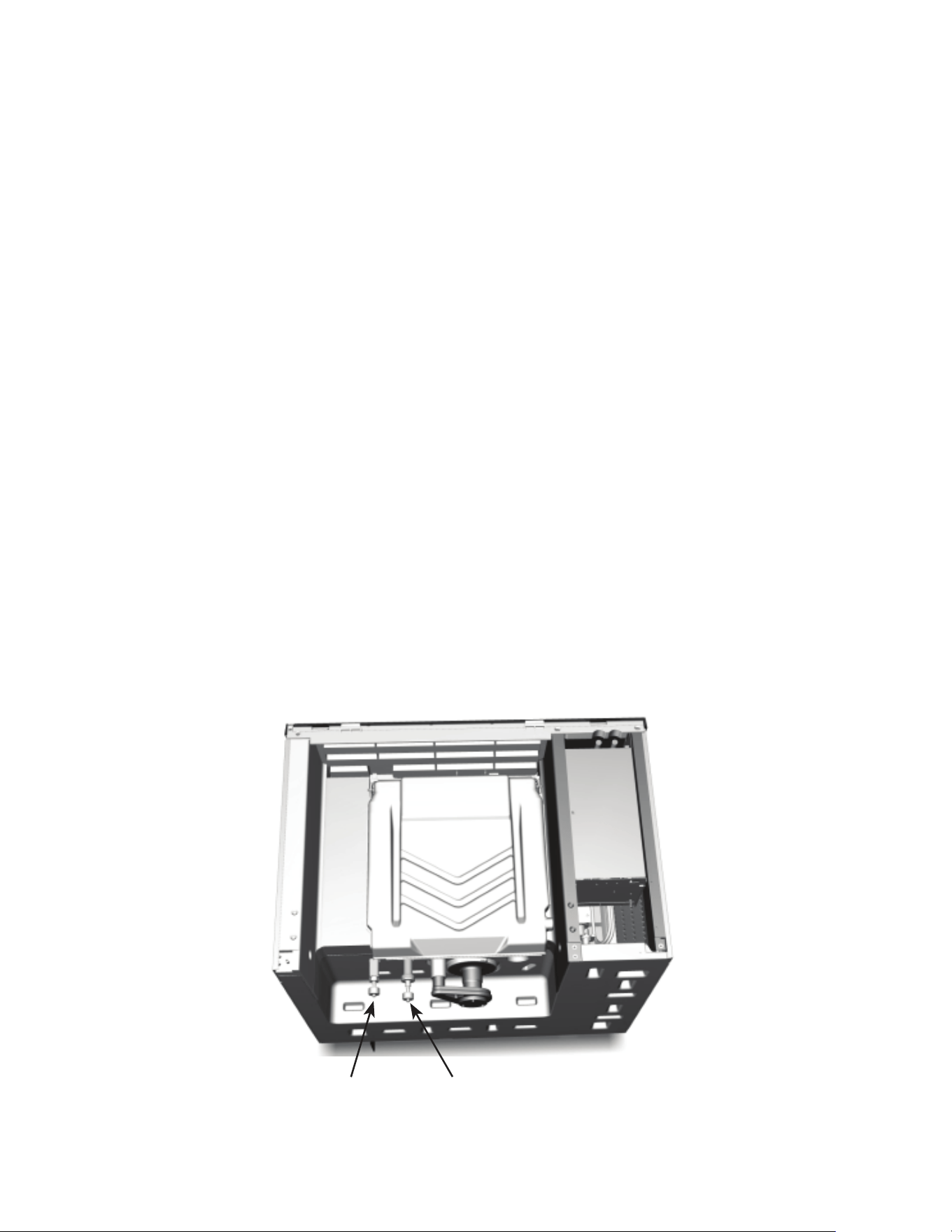
80 - Modular Part Number 000018624 Rev 00 4/26
Ice Machine Does Not Cycle Into Harvest when the
Harvest Float Is Down/Closed
NOTE: The ice machine will make a thick or double slab
when a new freeze cycle is started with ice already present
on the evaporator.
Two of the most common scenarios are:
• Power is cycled off/on with ice on the evaporator.
• The water curtain/bin switch is opened/closed in the
harvest cycle before the ice releases.
Remove all ice from the evaporator before starting
diagnostic procedures.
Freeze Time Lock-In Feature
The ice machine control system incorporates a freeze
time lock-in feature. This prevents the ice machine from
short cycling in and out of harvest. The control board locks
the ice machine in the freeze cycle for six minutes. After
six minutes a harvest cycle can be initiated. To allow the
service technician to initiate a harvest cycle without delay,
this feature is not used on the first cycle after moving the
toggle switch to OFF and back to ON.
Harvest Float SwitchIce Thickness Float Switch
Part Number 000018624 Rev 00 4/26 Modular - 81
Step 1 Disconnect power to the ice machine, remove
the electrical panel to allow viewing of the control board
lights. Disconnect the harvest float switch wire from the
control board and place a jumper on the control board
harvest switch terminals.
Step 2 Bypass the freeze time lock-in feature by
moving the toggle switch Off/On to cycle the ice machine
on. Wait until water flows over the evaporator, then refer
to chart.
Result Correction
10 seconds into the freeze
cycle the ice machine cycles
from freeze to harvest and
the control board harvest light
energizes.
The ice thickness float switch,
connectors or wiring are
causing the malfunction.
The harvest light comes on, but
the ice machine remains in the
freeze cycle.
The ice machine is in a 6 minute
freeze lock -
Cycle on/off and retest.
The harvest light stays off and
the ice machine remains in
freeze.
Replace the control board.
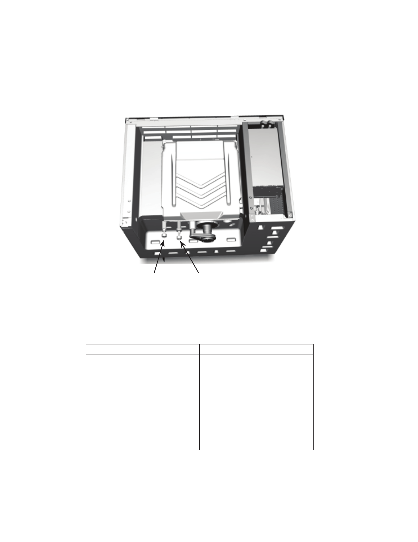
82 - Modular Part Number 000018624 Rev 00 4/26
Ice Machine Cycles Into Harvest Before the Harvest Float
Is Down/Closed
Step 1 Disconnect power to the ice machine, remove
the electrical panel to allow viewing of the control board
lights and disconnect the float switch harness from the
control board.
Harvest Float SwitchIce Thickness Float Switch
Step 2 Reapply power and move the toggle switch to
Ice to bypass the freeze time lock-in feature. Wait until
water flows over the evaporator, then refer to chart.
Result Correction
The harvest light does not come
on and the ice machine stays
in freeze.
The ice thickness float switch,
connectors or wiring are
causing the malfunction. Refer
to float switch diagnostics.
10 seconds into the freeze
cycle the ice machine cycles
from freeze to harvest and
the control board harvest light
energizes.
Replace the control board.

Part Number 000018624 Rev 00 4/26 Modular - 83
Ice Production Check
The amount of ice a machine produces directly relates to
the operating water and air temperatures. This means an
ice machine with a 70°F (21°C) ambient temperature and
50°F (10°C) water produces more ice than the same ice
machine with 90°F (32°C) ambient and 70°F (21°C) water.
1. Determine the ice machine operating conditions:
Air temp entering condenser:____°
Air temp around ice machine:____°
Water temp entering sump trough:____°
2. Refer to the appropriate 24-Hour Ice Production
Chart. Use the operating conditions determined in
Step 1 to find published 24-Hour Ice Production:_____
• Times are in minutes.
Example: 1 min. 15 sec. converts to 1.25 min.
(15 seconds ÷ 60 seconds = .25 minutes)
• Weights are in pounds.
Example: 2 lb. 6 oz. converts to 2.375 lb.
(6 oz. ÷ 16 oz. = .375 lb.)
3. Perform an ice production check using the formula
below.
1. + =
Freeze Time Harvest Time Total Cycle Time
2. 1440 ÷ =
Minutes in 24 Hrs.
Total Cycle Time Cycles per Day
3. x =
Weight of One
Harvest
Cycles per Day Actual 24-Hour
Production
Weighing the ice is the only 100% accurate check.
4. Compare the results of Step 3 with Step 2. Ice
production is normal when these numbers match
closely. If they match closely, determine if:
• Another larger ice machine is required.
• Relocating the existing equipment to lower the
load conditions is required.

84 - Modular Part Number 000018624 Rev 00 4/26
Installation/Visual Inspection Checklist
Ice machine is not level
• Level the ice machine
Condenser is dirty
• Clean the condenser
Water filtration is plugged (if used)
• Install a new water filter
Water drains are not run separately and/or are not
vented
• Run and vent drains according to the Installation
Manual

Part Number 000018624 Rev 00 4/26 Modular - 85
Water System Checklist
A water-related problem often causes the same symptoms
as a refrigeration system component malfunction.
Example: A water dump valve leaking during the freeze
cycle, a system low on charge, and a starving TXV have
similar symptoms.
Water system problems must be identified and eliminated
prior to replacing refrigeration components.
Water area (evaporator) is dirty
• Clean as needed
Water inlet pressure not between 20 and 80 psig (1–5 bar,
138–552 kPa)
• Install a water regulator valve or increase the water
pressure
Incoming water temperature is not between 35°F (1.7°C)
and 90°F (32.2°C)
• If too hot, check the hot water line check valves in
other store equipment
Water filtration is plugged (if used)
• Install a new water filter
Vent tube is not installed on water outlet drain
• See Installation Instructions
Hoses, fittings, etc., are leaking water
• Repair/replace as needed
Water valve is stuck open, closed or is leaking
• Clean/replace as needed

86 - Modular Part Number 000018624 Rev 00 4/26
Water is spraying out of the sump trough area
• Stop the water spray
Uneven water flow across the evaporator
• Clean the ice machine
Water is freezing behind the evaporator
• Correct the water flow
Plastic extrusions and gaskets are not secured to the
evaporator
• Remount/replace as needed

Part Number 000018624 Rev 00 4/26 Modular - 87
Ice Formation Pattern
Evaporator ice formation pattern analysis is helpful in ice
machine diagnostics.
Analyzing the ice formation pattern alone cannot diagnose
an ice machine malfunction. However, when this analysis
is used along with the Refrigeration System Operational
Analysis Table, it can help diagnose an ice machine
malfunction.
OUTLET
INLET
Example of Evaporator Tubing Routing
Normal Ice Formation
Ice forms across the entire evaporator surface.
At the beginning of the Freeze cycle, it may appear that
more ice is forming on the inlet of the evaporator than at
the outlet. At the end of the Freeze cycle, ice formation
at the outlet will be close to, or just a bit thinner than,
ice formation at the inlet. The dimples in the cubes at the
outlet of the evaporator may be more pronounced than
those at the inlet. This is normal.
If ice forms uniformly across the evaporator surface, but
does not do so in the proper amount of time, this is still
considered a normal ice fill pattern.

88 - Modular Part Number 000018624 Rev 00 4/26
Extremely Thin at Evaporator Outlet
There is no ice, or a considerable lack of ice formation on
the outlet of the evaporator.
Examples: No ice at all at the outlet of the evaporator, but
ice forms at the inlet half of the evaporator. Or, the ice at
the outlet of the evaporator reaches the correct thickness,
but the outlet of the evaporator already has 1/2" to 1"
(12 to 25 mm) of ice formation.
Extremely Thin at Evaporator Inlet
There is no ice, or a considerable lack of ice formation at
the inlet of the evaporator. Examples: The ice at the outlet
of the evaporator reaches the correct thickness, but there
is no ice formation at all at the inlet of the evaporator.
No Ice Formation
The ice machine operates for an extended period, but
there is no ice formation at all on the evaporator.
Evaporator Tubing Routing
Routing of the tubing on the back of the evaporator
determines the ice fill pattern failure mode.
One Evaporator, One TXV Models
The evaporator outlet tubing does not exit directly at the
top of the evaporator, but exits several inches below the
top of the evaporator. Extremely Thin at the Evaporator
Outlet will first be visible several inches below the top of
the evaporator. Extremely Thin at Evaporator Inlet will first
be visible at the bottom of the evaporator.
Part Number 000018624 Rev 00 4/26 Modular - 89
One Evaporator, Two TXV 48" Models
Tubing routing for one evaporator with two TXV’s is
different. The evaporator has two inlets and outlets. Fill
pattern varies depending on which circuit is affected,
Extremely Thin at the Evaporator Outlet
Will first be visible 1/3 of the way down the evaporator.
Only one side of the evaporator may be affected
depending on failure. A TXV failure will usually show on
only one side, while low on refrigerant can affect one or
both sides depending on the amount of refrigerant loss
and ambient temperature.
Extremely Thin at the Evaporator Inlet
Will show at the bottom of the evaporator. Depending on
the failure either the entire bottom of the evaporator or
one side of the bottom of the evaporator may be affected.
ICE
ICE
ICE

90 - Modular Part Number 000018624 Rev 00 4/26
Analyzing Suction Pressure
The suction pressure gradually drops throughout the
freeze cycle. The actual suction pressure (and drop rate)
changes as the air and water temperature entering the
ice machine changes. These variables also determine the
freeze cycle times.
To analyze and identify the proper suction pressure drop
throughout the freeze cycle, compare the published
suction pressure to the published freeze cycle time.
NOTE: Analyze discharge pressure before analyzing suction
pressure. High or low discharge pressure may be causing
high or low suction pressure.
Part Number 000018624 Rev 00 4/26 Modular - 91
Procedure
Step
1. Determine the ice machine operating conditions.
Example:
Air temp. entering condenser: 90°F/32.2°C
Air temp. around ice machine: 80°F/26.7°C
Water temp. entering water fill valve: 70°F/21.1°C
2A. Refer to “Cycle Time” and “Operating Pressure” charts for ice
machine model being checked. Using operating conditions from
Step 1, determine published freeze cycle time and published
freeze cycle suction pressure.
Example:
Published freeze cycle time: 14.8 - 15.9 minutes
Published freeze cycle suction pressure: 65 - 26 psig
2B. Compare the published freeze cycle time and published
freeze cycle suction pressure. Develop a chart.
Example:
Published Freeze Cycle Time (minutes)
1 2 4 7 10 12 14
| | | | | | |
65 55 47 39 34 30 26
Published Freeze Cycle Suction Pressure (psig)
In the example, the proper suction pressure should be
approximately 39 psig at 7 minutes; 30 psig at 12 minutes; etc.
3. Perform an actual suction pressure check at the beginning,
middle and end of the freeze cycle. Note the times at which the
readings are taken.
Example:
Manifold gauges were connected to the example ice machine
and suction pressure readings taken as follows: ________ PSIG
Beginning of freeze cycle: 79 (at 1 min.)
Middle of freeze cycle: 48 (at 7 min.)
End of freeze cycle: 40 (at 14 min.)
4. Compare the actual freeze cycle suction pressure (Step 3)
to the published freeze cycle time and pressure comparison
(Step 2B). Determine if the suction pressure is high, low or
acceptable.
Example:
In this example, the suction pressure is considered high
throughout the freeze cycle. It should have been:
Approximately 65 psig (at 1 minute) – not 79
Approximately 39 psig (at 7 minutes) – not 48
Approximately 26 psig (at 14 minutes) – not 40

92 - Modular Part Number 000018624 Rev 00 4/26
SUCTION PRESSURE HIGH CHECKLIST
Improper Installation
• Refer to “Installation/Visual Inspection Checklist” on
page 84.
Discharge Pressure
• Discharge pressure is too high and is affecting suction
pressure, refer to “Discharge Pressure High Checklist”
on page 96.
Improper Refrigerant Charge
• Overcharged
• Wrong type of refrigerant
• Non-condensible in system
Other
• Non-OEM components in system
• Harvest valve leaking
• TXV flooding (check bulb mounting)
• Defective compressor

Part Number 000018624 Rev 00 4/26 Modular - 93
SUCTION PRESSURE LOW CHECKLIST
Improper Installation
• Refer to “Installation/Visual Inspection Checklist” on
page 84.
Discharge Pressure
• Discharge pressure is too low, and is affecting suction
pressure, refer to “Freeze Cycle Discharge Pressure
Low Checklist” on page 96
Improper Refrigerant Charge
• Undercharged
• Wrong type of refrigerant
Other
• Non-OEM components in system
• Improper water supply over evaporator refer to
“Water System Checklist” on page 85.
• Loss of heat transfer from tubing on back side of
evaporator
• Restricted/plugged liquid line drier
• Restricted/plugged tubing in suction side of
refrigeration system
• TXV starving
NOTE: Do not limit your diagnosis to only the items listed
in the checklists.
94 - Modular Part Number 000018624 Rev 00 4/26
Comparing Evaporator Inlet and Outlet Temperatures
The temperatures of the suction lines entering and leaving
the evaporator alone cannot diagnose an ice machine.
However, comparing these temperatures during the freeze
cycle, along with the Refrigeration System Operational
Analysis Table, can help diagnose an ice machine
malfunction.
The actual temperatures entering and leaving the
evaporator vary by model, and change throughout the
freeze cycle. This makes documenting the “normal”
inlet and outlet temperature readings difficult. The key
to the diagnosis lies in the difference between the two
temperatures five minutes into the freeze cycle. These
temperatures must be within 7°F (4°C) of each other.
Use this procedure to document freeze cycle inlet and
outlet temperatures.
1. Use a quality temperature meter, capable of taking
temperature readings on curved copper lines.
2. Attach the temperature meter sensing device to the
copper lines entering and leaving the evaporator.
Important
Do not simply insert the sensing device under the
insulation. It must be attached to and reading the
actual temperature of the copper line.
3. Wait five minutes into the freeze cycle.
4. Record the temperatures below and determine the
difference between them.
___________ ___________ ___________
Inlet Temperature Difference must be within
7°F (4°C) at 5 minutes into
the freeze cycle
Outlet
Temperature
5. Use this with other information gathered on the
Refrigeration System Operational Analysis Table to
determine the ice machine malfunction.
Part Number 000018624 Rev 00 4/26 Modular - 95
Analyzing Discharge Pressure
1. Determine the ice machine operating conditions:
Air temp. entering condenser ______
Air temp. around ice machine ______
Water temp. entering sump trough ______
2. Refer to “Cycle Times, 24 Hr. Ice Production and
Refrigerant Pressure Charts” on page 149 for ice
machine being checked.
Use the operating conditions determined in Step 1 to find
the published normal discharge pressures.
Freeze Cycle ______
Harvest Cycle ______
3. Perform an actual discharge pressure check.
Freeze Cycle
PSIG
Harvest Cycle
PSIG
Beginning of
Cycle __________ __________
Middle of
Cycle __________ __________
End of
Cycle __________ __________
4. Compare the actual discharge pressure (Step 3) with
the published discharge pressure (Step 2).
The discharge pressure is normal when the actual
pressure falls within the published pressure range for the
ice machine’s operating conditions. It is normal for the
discharge pressure to be higher at the beginning of the
freeze cycle (when load is greatest), then drop throughout
the freeze cycle.

96 - Modular Part Number 000018624 Rev 00 4/26
DISCHARGE PRESSURE HIGH CHECKLIST
Improper Installation
• Refer to “Installation/Visual Inspection Checklist” on
page 84.
Condenser Air Flow
• High inlet air temperature
• Condenser discharge air re-circulation
• Dirty condenser fins
• Defective fan cycling control
• Defective fan motor
Improper Refrigerant Charge
• Overcharged
• Non-condensible in system
• Wrong type of refrigerant
Other
• Non-OEM components in system
• High side refrigerant lines/component restricted
(before mid-condenser)
FREEZE CYCLE DISCHARGE PRESSURE LOW CHECKLIST
Improper Installation
• Refer to “Installation/Visual Inspection Checklist” on
page 84.
Improper Refrigerant Charge
• Undercharged
• Wrong type of refrigerant
Other
• Non-OEM components in system
• High side refrigerant lines/component restricted
(before mid-condenser)
• Defective fan cycle control
NOTE: Do not limit your diagnosis to only the items listed
in the checklists.

Part Number 000018624 Rev 00 4/26 Modular - 97
Harvest Valve
General
The harvest valve is an electrically operated valve that
opens when energized, and closes when de-energized.
Normal Operation
The valve is de-energized (closed) during the freeze cycle
and energized (open) during the harvest cycle. The valve is
positioned between the compressor discharge line and the
evaporator and performs two functions:
1. Prevents refrigerant from entering the evaporator
during the freeze cycle.
The harvest valve is not used during the freeze cycle.
The harvest valve is de-energized (closed) preventing
refrigerant flow from the discharge line into the
evaporator.
2. Allows refrigerant vapor to enter the evaporator in
the harvest cycle.
During the harvest cycle, the harvest valve is
energized (open) allowing refrigerant gas from the
discharge line of the compressor to flow into the
evaporator. The heat is absorbed by the evaporator
and allows release of the ice slab.
Exact pressures vary according to ambient temperature
and ice machine model. Harvest pressures can be found
in the Cycle Time/24 Hour Ice Production/ Refrigerant
Pressure Charts in this book.

98 - Modular Part Number 000018624 Rev 00 4/26
HARVEST VALVE ANALYSIS
The valve can fail in two positions:
• Valve will not open in the harvest cycle.
• Valve remains open during the freeze cycle.
Valve will not open in the harvest cycle
Although the circuit board has initiated a harvest cycle,
the evaporator temperature remains unchanged from the
freeze cycle.
Valve remains open in the freeze cycle:
Symptoms of a harvest valve remaining partially open
during the freeze cycle can be similar to symptoms of an
expansion valve or compressor problem. Symptoms are
dependent on the amount of leakage in the freeze cycle.
A small amount of leakage will cause increased freeze
times and an ice fill pattern that is “Thin at the Outlet”, but
fills in at the end of the cycle.
As the amount of leakage increases, the length of the
freeze cycle increases and the amount of ice at the outlet
of the evaporator decreases.
Refer to the Parts Manual for proper valve application. If
replacement is necessary, use only “original” replacement
parts.

Part Number 000018624 Rev 00 4/26 Modular - 99
Use the following procedure and table to help determine
if a harvest valve is remaining partially open during the
freeze cycle.
1. Wait five minutes into the freeze cycle.
2. Feel the inlet of the harvest valve(s).
Important
Feeling the harvest valve outlet or across the harvest
valve itself will not work for this comparison.
The harvest valve outlet is on the suction side (cool
refrigerant). It may be cool enough to touch even if the
valve is leaking.
3. Feel the compressor discharge line.
n
Warning
The inlet of the harvest valve and the compressor
discharge line could be hot enough to burn your hand.
Just touch them momentarily.
4. Compare the temperature of the inlet of the harvest
valves to the temperature of the compressor
discharge line.
100 - Modular Part Number 000018624 Rev 00 4/26
Findings Comments
The inlet of the harvest valve
is cool enough to touch and
the compressor discharge line
is hot.
Cool & Hot
This is normal as the discharge
line should always be too hot
to touch and the harvest valve
inlet, although too hot to touch
during harvest, should be
cool enough to touch after 5
minutes into the freeze cycle.
The inlet of the harvest
valve is hot and approaches
the temperature of a hot
compressor discharge line.
Hot & Hot
This is an indication something
is wrong, as the harvest
valve inlet did not cool down
during the freeze cycle. If
the compressor dome is also
entirely hot, the problem is
not a harvest valve leaking, but
rather something causing the
compressor (and the entire ice
machine) to get hot.
Both the inlet of the harvest
valve and the compressor
discharge line are cool enough
to touch.
Cool & Cool
This is an indication something
is wrong, causing the
compressor discharge line to
be cool to the touch. This is
not caused by a harvest valve
leaking.
5. Record your findings on the table.

Part Number 000018624 Rev 00 4/26 Modular - 101
Discharge Line Temperature Analysis
GENERAL
Knowing if the discharge line temperature is increasing,
decreasing or remaining constant can be an important
diagnostic tool. Maximum compressor discharge line
temperature on a normally operating ice machine steadily
increases throughout the freeze cycle. Comparing the
temperatures over several cycles will result in a consistent
maximum discharge line temperature.
Ambient air temperatures affect the maximum discharge
line temperature.
Higher ambient air temperatures at the condenser = higher
discharge line temperatures at the compressor.
Lower ambient air temperatures at the condenser = lower
discharge line temperatures at the compressor.
Regardless of ambient temperature, the freeze cycle
discharge line temperature will be higher than 150°F (66°C)
on a normally operating ice machine.
PROCEDURE
Connect a temperature probe on the compressor discharge
line within 6" (15 cm) of the compressor. Observe the
discharge line temperature for the last three minutes of
the freeze cycle and record the maximum discharge line
temperature.

102 - Modular Part Number 000018624 Rev 00 4/26
Discharge Line Temperature Above 150°F (66°C) at End of
Freeze Cycle:
Ice machines that are operating normally will have
consistent maximum discharge line temperatures above
150°F (66°C).
Verify the expansion valve sensing bulb is positioned and
secured correctly.
Discharge Line Temperature Below 150°F (66°C) at End of
Freeze Cycle
Ice machines that have a flooding expansion valve will have
a maximum discharge line temperature that decreases
each cycle.
Verify the expansion valve sensing bulb is 100% insulated
and sealed airtight. Condenser air contacting an incorrectly
insulated sensing bulb will cause overfeeding of the
expansion valve.

Part Number 000018624 Rev 00 4/26 Modular - 103
Final Analysis - Self-contained Air, Water & Remote
Condenser Models
The column with the highest number of check marks
identifies the refrigeration problem.
COLUMN 1 HARVEST VALVE LEAKING
Replace the valve as required.
COLUMN 2 LOW CHARGE/TXV STARVING
Normally, a starving expansion valve only affects the freeze
cycle pressures, not the harvest cycle pressures. A low
refrigerant charge normally affects both pressures. Verify
the ice machine is not low on charge before replacing an
expansion valve.
1. Add refrigerant charge to verify a low charge (air and
water self-contained only). Do not add more than
30% of nameplate refrigerant charge. If the problem is
corrected, the ice machine is low on charge.
NOTE: Do not add charge to remote models. The
symptoms of a remote low on charge will result in a service
long freeze in cool ambient temperatures. Check the liquid
line temperature at the ice machine. The liquid line will be
hot with a normal or below normal head pressure in freeze
when the ice machine is low on refrigerant.
2. Find the refrigerant leak. The ice machine must
operate with the nameplate charge. If the leak cannot
be found, proper refrigerant procedures must still be
followed. Change the liquid line drier. Then, evacuate
and weigh in the proper charge.
3. If the problem is not corrected by adding charge, the
expansion valve is faulty.

104 - Modular Part Number 000018624 Rev 00 4/26
COLUMN 3 TXV FLOODING OR REFRIGERANT
OVERCHARGE
A loose or improperly mounted expansion valve bulb
causes the expansion valve to flood. Check bulb mounting,
insulation, etc, before changing the valve. Verify refrigerant
amount is correct by weighing recovered refrigerant before
replacing a TXV.
COLUMN 4 COMPRESSOR
Replace the compressor. To receive warranty credit, the
compressor ports must be properly sealed by crimping and
soldering them closed.
Part Number 000018624 Rev 00 4/26 Modular - 105
SYMPTOM #3 REMOTE CONDENSER
Traditional Remote Ice Machine – Long Harvest/Low
Production/Intermittent Service Limit 2
NO
NO
YES
YES
YES
Fails at night or in low
ambient - Operates normally
above 70°F (21°C)
Normal ice fill, Long harvest cycle,
Possible SL #2, Back of Cubes are not
melted at end of harvest cycle
Wet condenserwith
water during freeze
cycle
Liquid Line Temperature
Warm (Body Temperature)
Discharge line temperature is normal at the
end of the freeze cycle?
All Remotes = >150°F (65°C)
Liquid Line Temperature Cool
Liquid Line
Temperature Hot
Replace Headmaster
System low on refrigerant
Refer to Freeze Cycle
Analysis Chart
106 - Modular Part Number 000018624 Rev 00 4/26
YES
NO
YES
NO
YES
YES
NO
YES
NO
Is Harvest Valve Energized?
Refer to Wiring Diagram and
Sequence of Operaon
Head Pressure High, Sucon
Pressure Low in Harvest?
Replace Harvest Valve
Head Pressure Low, Sucon
Pressure Low in Harvest?
Refer to Harvest Pressure
Regulang Valve Diagnoscs
Repeat this flowchart and
verify all data
Head Pressure Normal,
Sucon Pressure Normal
in Harvest?
Refer to Symptom #4
Will Not Harvest, Freeze Cycle
Normal & Ice Cubes are Melted
Flowchart
Part Number 000018624 Rev 00 4/26 Modular - 107
SYMPTOM #3 SELFCONTAINED AIR OR
WATERCOOLED
Ice Machine Will Not Harvest – Freeze Cycle is Normal
and ice Cubes Are Not Melted After Harvest
NO
YES
YES
YES
NO
NO
YES
Low Producon, Normal Fill
Paern, Long Harvest Cycle,
Possible SL #2, Back of Cubes Are
Not Melted
Discharge line temperature is greater than 150°F
(65°C) at the end of the freeze cycle?
Refer to Symptom
#2 Freeze Cycle
Operaonal Analysis
Table
Refer to Sequence of
Operaon and Wiring
Diagram
Harvest Valve is Energized?
Head Pressure is High,
Sucon Pressure is Low in
Harvest? (Refer to Pressure
Charts)
Replace
Harvest
Valve
108 - Modular Part Number 000018624 Rev 00 4/26
NO
NO
YES
YES
NONO
NO
NO
YES
YES
NO
YES
Self Contained Air-cooled
Condenser?
Fan cycling Control
operates correctly in
freeze cycle?
Fan Cycling Control
Opens below setpoint in
harvest cycle?
Are you sure Discharge Line
Temperature is Normal?
Repeat this flowchart and
verify all data
Stops water flow 100%
in harvest cycle?
Maintains correct
pressure in freeze cycle?
Self Contained
Watercooled Condenser?
Replace Fan Cycling
Control
Adjust or Replace
Water Regulang
Valve
Refer To Tradional
Remote Ice Machine Only
Chart
Tradional Remote
Aircooled Condenser?
YES
YES
Part Number 000018624 Rev 00 4/26 Modular - 109
SYMPTOM #4
Ice Machine Will Not Harvest – Freeze Cycle Is Normal
and Ice Cubes Are Not Melted After Harvest
NO
NO
YES
YES
YES
NO
YES
NO
START
Are back of the cubes
melted at end of
harvest cycle?
Is Ice Machine
level?
Does ice remain
frozen to the
evaporator at the end
of the harvest cycle?
Refer to
Symptom #3 Ice
Machine will not
harvest
Is water flowing over
the evaporator in the
first 45 seconds of
harvest?
Level Ice
Machine
Refer to
Dump Valve
Diagnoscs
110 - Modular Part Number 000018624 Rev 00 4/26
NO
YES
YES
NO
*A damaged evaporator may not be repairable. For example: the top molding assembly is replaceable however the side moldings and/or the evaporator grid is not repairable.
Is the evaporator dirty or
damaged?*
(Dry evaporator first then
check) Dents, loose parons
or plang issues
Are ice thickness, cycle
mes and slab weights
correct?
Discharge line temperature is greater than
150°F (65°C) at the end of the freeze cycle?
Refer to Heavily Scaled
De-scaling Procedure
Refer to Symptom #2 Freeze
Cycle Operaonal Analysis
Table
Refer to Manual
Cleaning Procedure
Part Number 000018624 Rev 00 4/26 Modular - 111
Main Fuse
Function
The control board fuse stops ice machine operation if
electrical components fail causing high amp draw.
Specifications
• The main fuse is 250 Volt, 3.15 amp.
n
Warning
High (line) voltage is applied to the control board at
all times. Removing the control board fuse or cycling
the toggle switch Off/On will not remove the power
supplied to the control board.
Check Procedure
1. If the curtain light is on with the water curtain closed,
the fuse is good.
n
Warning
Disconnect electrical power to the entire ice machine
before proceeding.
2. Remove the fuse. Check the resistance across the fuse
with an ohmmeter.
Reading Result
Open (OL) Replace fuse
Closed (O) Fuse is good
Component Check Procedures

112 - Modular Part Number 000018624 Rev 00 4/26
Bin Switch
Function
Bin switch operation is controlled by the movement of the
water curtain. The bin switch has two main functions:
1. Terminating the harvest cycle and returning the ice
machine to the freeze cycle.
This occurs when the bin switch is opened and closed
again within 30 seconds of opening during the harvest
cycle.
2. Automatic ice machine shut-off.
If the storage bin is full at the end of a harvest cycle,
the sheet of cubes fails to clear the water curtain and
holds it down. After the water curtain is held down
for 30 seconds, the ice machine shuts off.
The ice machine remains off until enough ice is
removed from the storage bin to allow the sheet of
cubes to drop clear of the water curtain. As the water
curtain swings back to the operating position, the bin
switch closes and the ice machine restarts.
Important
The water curtain must be installed (bin switch closed)
to start ice making.
Check Procedure
1. Cycle the toggle switch OFF.
2. Watch the curtain light on the control board.
3. Move the water curtain upward, toward the
evaporator. The bin switch must close. The curtain
light “on” indicates the bin switch has closed properly.
4. Move the water curtain away from the evaporator.
The bin switch must open. The curtain light “off”
indicates the bin switch has opened properly.

Part Number 000018624 Rev 00 4/26 Modular - 113
Ohm Test
1. Disconnect the bin switch wires from the control
board.
2. Connect an ohmmeter to the disconnected bin switch.
3. Cycle the bin switch open and closed numerous times
by opening and closing the water curtain.
NOTE: To prevent misdiagnosis:
• Always use the water curtain magnet to cycle the
switch (a larger or smaller magnet will affect switch
operation).
• Watch for consistent readings when the bin switch is
cycled open and closed (bin switch failure could be
erratic).

114 - Modular Part Number 000018624 Rev 00 4/26
Float Switch
Function
Open and close to indicate to the control board the level of
water in the water trough.
Specifications
Normally closed, float operated magnetic reed switch.
The float switch contacts are closed in the down position.
When water raises the float to the up position the magnet
in the float opens the contacts.
Check Procedure
The ice machine uses two float switches.
Ice Thickness Float - Indicates the water level has been
reached.
Harvest Float - Indicates a harvest cycle needs to be
initiated.
Initial testing can be performed by viewing the control
board light(s) while raising and lowering the float. The
corresponding control board light must turn on and off
when the float is raised and lowered.
Harvest Float Switch:
A. The light must be on in the up position.
B. The light must be off in the down position.
Ice Thickness Float Switch:
A. The light must be off in the down position.
B. The light must be on in the up position.
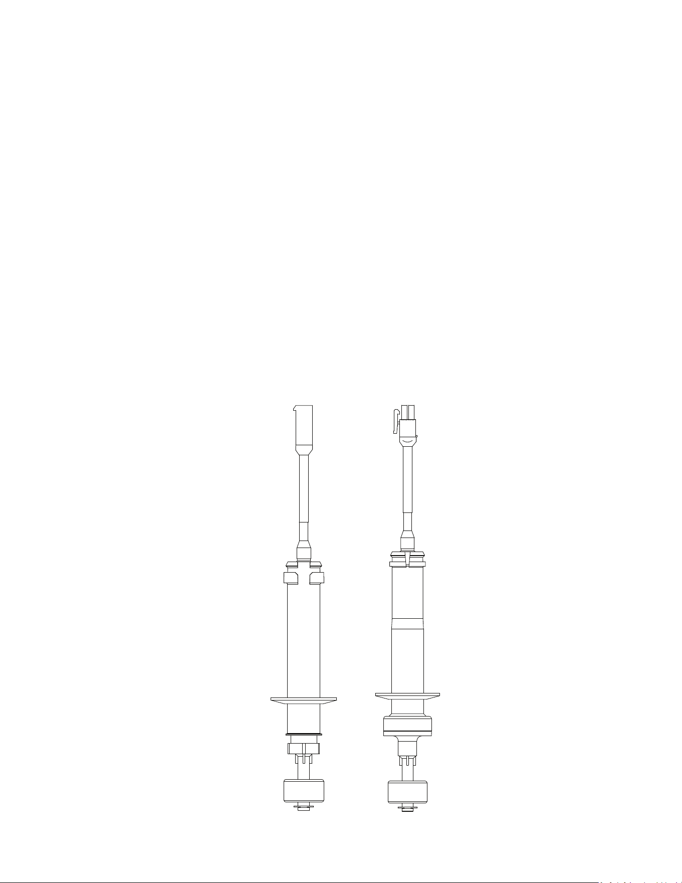
Part Number 000018624 Rev 00 4/26 Modular - 115
If the control board light does not respond to the float,
proceed with Step 1 below.
1. Disconnect power to the ice machine and pull the
float switch and connector through the ice machine
base and disconnect.
2. Attach an ohm meter lead to each float switch wire.
3. Place the float in the down position - The float switch
must be closed.
4. Place the float in the up position - The float switch
must be open.
5. If the float tests good, ohm the interconnecting wires
to the control board and inspect connectors.
NOTE: Make adjustments with the ice machine in the off
position. Making adjustments during the freeze cycle may
produce an initial sheet of ice that is thicker than future
cycles.
ICE THICKNESS
FLOAT
HARVEST
FLOAT

116 - Modular Part Number 000018624 Rev 00 4/26
Compressor Electrical Diagnostics
The compressor does not start or will trip repeatedly on
overload.
Check Resistance (Ohm) Values
NOTE: Compressor windings can have very low ohm
values. Use a properly calibrated meter.
Perform the resistance test after the compressor cools. The
compressor dome should be cool enough to touch (below
120°F/49°C) to ensure that the overload is closed and the
resistance readings will be accurate.
Single Phase Compressors
1. Disconnect power and remove the wires from the
compressor terminals.
2. The resistance values between C and S and between
C and R, when added together should equal the
resistance value between S and R.
3. If the overload is open, there will be a resistance
reading between S and R, and open readings between
C and S and between C and R. Allow the compressor
to cool, then check the readings again.
Check Motor Windings to Ground
Check continuity between all three terminals and the
compressor shell or copper refrigeration line. Scrape metal
surface to get good contact. If continuity is present, the
compressor windings are grounded and the compressor
should be replaced.
To determine if the compressor is seized, check the amp
draw while the compressor is trying to start.

Part Number 000018624 Rev 00 4/26 Modular - 117
Compressor Drawing Locked Rotor
The two likely causes of this are:
• Defective starting component
• Mechanically seized compressor
To determine which you have:
1. Install high and low side gauge.
2. Try to start the compressor.
3. Watch the pressures closely.
• If the pressures do not move, the compressor is
seized. Replace the compressor.
• If the pressures move, the compressor is
turning slowly and is not seized. Check the start
components.
Compressor Drawing High Amps
The continuous amperage draw on start-up should not be
near the maximum fuse size indicated on the serial tag.
The wiring must be correctly sized to minimize voltage
drop at compressor start-up. The voltage when the
compressor is trying to start must be within ±10% of the
nameplate voltage.

118 - Modular Part Number 000018624 Rev 00 4/26
PTCR
The PTCR allows current to flow through the start winding
at compressor startup. Current flow heats the ceramic
discs in the PTCR. The electrical resistance increases with
temperature and stops all except a trickle of current flow
through the start winding. The small flow of current keeps
the PTCR hot (260°F/127°C) and the start winding out of
the circuit.
The PTCR must be cooled before attempting to start the
compressor, otherwise the PTCR will heat up too quickly
and stop current flow through the start winding before the
compressor motor reaches full speed.
n
Warning
Disconnect electrical power to the entire ice machine
at the building electrical disconnect box before
proceeding.
NOTE: If a PTCR is dropped internal damage can occur
to the ceramic PTCR discs. The ceramic disc can chip and
cause arcing which leads to PTCR failure. Since there is no
way to open the PTCR in order to determine if the ceramic
disc is chipped or not, it must be discarded when dropped.
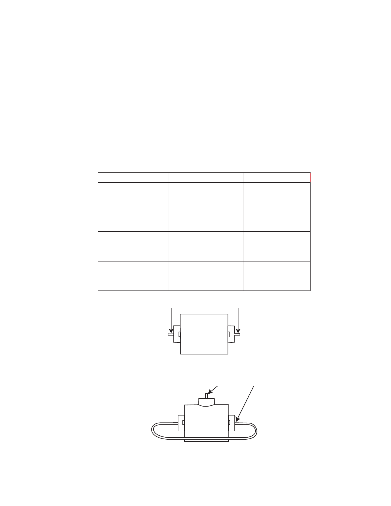
Part Number 000018624 Rev 00 4/26 Modular - 119
PTCR Operation Check
1. Visually inspect the PTCR. Check for signs of physical
damage.
NOTE: The PTCR case temperature may reach 210°F
(100°C) while the compressor is running. This is normal. Do
not change a PTCR just because it is hot.
2. Wait at least 10 minutes for the PTCR to cool to room
temperature.
3. Remove the PTCR from the ice machine.
4. Measure the resistance of the PTCR as shown. The
resistance reading must be between:
PTCR Ohm Value Amp Part Number
Two Terminal Black
Cera-Mite 305C2
60 to 110 12 000014323
Two Terminal
Black or Blue
Cera-Mite 305C20
24 to 46 10 8505003
Three Terminal
Blue or Tan
Cera-Mite 305C19
21 to 39 18 8504993
Three Terminal
Blue or Tan
Cera-Mite 305C09
10 to 20 36 8504913
Two Terminal PTCR
Three Terminal PTCR
Measure Resistance at Ends
Measure Resistance at Center and End
Leave Jumper Wire Attached
120 - Modular Part Number 000018624 Rev 00 4/26
Fan Cycle Control
Function
Cycles the fan motor on and off to maintain proper
operating discharge pressure.
The fan cycle control closes on an increase, and opens on a
decrease in discharge pressure.
Specifications
Model
Cut-In
(Close)
Cut-Out
(Open)
KT0300 K0350 KT0400 KT0420
K0420 KT0500 K0500 K0600
KT0700 KT1000 KT1700
335 psig ±5
2310 kPa ±5
275 psig ±5
1896 kPa ±5
K1000 K1350 K1800
385 psig ±5
2654 kPa ±5
305 psig ±5
2103 kPa ±5
KP0300 KP0400 KP0420
KP0500 KP0700 KP1000
200 psig ±5
(1379 kPa ±34)
150 psig ±5
(1030 kPa ±34)
Check Procedure
Disconnect electrical power to the ice machine at the
electrical service disconnect.
Verify fan motor windings are not open or grounded, and
fan spins freely.
Connect manifold gauge to ice machine.
Hook voltmeter in parallel across the fan cycle control,
leaving wires attached.
Reconnect electrical power to the ice machine and Cycle
the toggle switch On.
Wait until water flows over the evaporator then refer to
chart below.
System
Pressure:
Reading
Should Be:
Fan
Should Be:
above cut-in 0 volts running
below cut-out line voltage off
Part Number 000018624 Rev 00 4/26 Modular - 121
High Pressure Cutout (HPCO) Control
Function
Stops the ice machine if subjected to excessive high-side
pressure. The HPCO control is normally closed, and opens
on a rise in discharge pressure.
Specifications
Specifications
Refrigerant Cut-Out Cut-In
R410A
600 psig ±10
(4136 kPa ±69)
450 psig ±20
(3103 kPa ±138)
R290
250 psig ±10
(1724 kPa ±69)
350 psig ±20
(2413 kPa ±138)
Automatic Reset
Check Procedure
1. Move toggle switch to OFF.
2. Connect manifold gauge.
3. Hook voltmeter in parallel across the HPCO, leaving
wires attached.
4. On water-cooled models, close the water service
valve to the water condenser inlet. On self-contained
air-cooled models, disconnect the fan motor.
5. Move toggle switch to ON.
6. No water or air flowing through the condenser will
cause the HPCO control to open because of excessive
pressure. Watch the pressure gauge and record the
cut-out pressure.
n
Warning
If discharge pressure exceeds 600 psig - 4137 kPa and
the HPCO control does not cut out, cycle the toggle
switch Off to stop ice machine operation.
Replace the HPCO control if it:
• Will not reset
• Does not open at the specified cut-out point

122 - Modular Part Number 000018624 Rev 00 4/26
Refrigeration Components
HEAD PRESSURE CONTROL VALVE
Koolaire remote systems require head pressure control
valves with special settings. Replace defective head
pressure control valves only with “original” Koolaire
replacement parts.
Refrigerant Charge Verification
The correct amount of refrigerant (name plate charge) is
required to operate correctly at all ambient conditions.
An ice machine with an overcharge or undercharge of
refrigerant may function properly at higher ambient
temperatures and fails at lower ambient temperatures.
Symptoms of incorrect refrigerant amount are:
• Works during the day and malfunctions at night, and/
or fails whenever the outdoor temperature drops.
• A Safety limit is stored in control board memory.
Refrigerant loss and ambient temperature are directly
related to each other. As the ambient temperature drops,
more refrigerant is stored in the condenser.
When the refrigerant charge and ambient temperature
create an undercharge of refrigerant in the freeze cycle,
the receiver dip tube will lose it’s liquid seal. Without liquid
refrigerant to the TXV, the ice machine fails to make a full
sheet of ice in 60 minutes and a safety limit #1 results.
NOTE: When a head pressure control valve is being
replaced or refrigerant charge is suspected, verify the
refrigerant charge is correct by recovering the refrigerant,
weighing and comparing to the nameplate amount.
Refer to Refrigerant Recovery/Evacuation for recovery
procedures.

Part Number 000018624 Rev 00 4/26 Modular - 123
FREEZE CYCLE OPERATION ALL MODELS
The head pressure control valve is non adjustable.
At ambient temperatures of approximately 70°F (21°C)
or above, refrigerant flows through the valve from the
condenser to the receiver inlet. At temperatures below
this (or at higher temperatures if it is raining), the head
pressure control dome’s nitrogen charge closes the
condenser port and opens the bypass port from the
compressor discharge line.
In this modulating mode, the valve maintains minimum
head pressure by building up liquid in the condenser and
bypassing discharge gas directly to the receiver.
HARVEST CYCLE OPERATION
Remote Condenser Models
The head pressure control cycles into full bypass due to the
pressure drop when the harvest valve opens. Refrigerant
flows from the compressor to the evaporator through the
harvest valve and the head pressure valve is out of the
circuit.
Diagnostics
FREEZE CYCLE REMOTE CONDENSER
1. Determine if the coil is clean.
2. Determine the air temperature entering the
condenser.
3. Determine if the head pressure is high or low in
relationship to the outside temperature. (Refer to
the proper “Cycle Times/24-Hour Ice Production/
Refrigerant Pressure Charts”).
4. Determine the temperature of the liquid line entering
the receiver by feeling it. This line is normally warm;
“body temperature.”
5. Using the information gathered, refer to the chart.
124 - Modular Part Number 000018624 Rev 00 4/26
NOTE: A head pressure control valve that will not
bypass, will function properly with condenser air
temperatures of approximately 70°F (21°C) or above.
When the temperature drops below 70°F (21°C), the head
pressure control valve fails to bypass and the ice machine
malfunctions. Lower ambient conditions can be simulated
by rinsing the condenser with cool water during the freeze
cycle.
Condition Probable
Cause
Corrective
Measure
Discharge Pressure - High
Liquid Line Temperature
- Hot
Valve stuck in
bypass
Replace valve
Discharge Pressure - Low
Liquid Line Temperature
- Cold
Valve not
bypassing
Replace valve
Discharge Pressure - Low
Liquid Line Temperature
- Hot
Ice Machine
Low on Charge
Refrigerant
Charge
Verification

Part Number 000018624 Rev 00 4/26 Modular - 125
Undercharge Symptoms
• Safety limit #1 or Safety limit #2 in control board
memory.
• Harvest cycle suction pressure is low.
• Harvest cycle discharge pressure is low.
• Liquid line entering receiver feels warm to hot in the
freeze cycle.
Overcharge Symptoms
• Safety limit #2 in control board memory, a flashing
alert and after pressing left arrow Long Harvest is
displayed.
• Harvest cycle discharge pressure is normal.
• Freeze cycle time, suction and discharge pressure are
normal and the ice machine will not harvest. The sheet
of ice cubes show little or no sign of melting when
removed from the evaporator after the harvest cycle
has been completed. (If the cubes are melted you have
a release problem, clean the ice machine).

126 - Modular Part Number 000018624 Rev 00 4/26
HARVEST PRESSURE REGULATING VALVE HPR
SYSTEM REMOTE CONDENSER ONLY
GENERAL
The harvest pressure regulating (HPR) system includes:
• Harvest pressure regulating solenoid valve (HPR
solenoid). This is an electrically operated valve which
opens when energized, and closes when de-energized.
• Harvest pressure regulating valve (HPR valve). This is a
pressure regulating valve which modulates open and
closed, based on the refrigerant pressure at the outlet
of the valve. The valve closes completely and stops
refrigerant flow when the pressure at the outlet rises
above the valve setting.
• The harvest pressure regulating valve is not adjustable.
FREEZE CYCLE
The HPR system is not used during the freeze cycle.
The HPR solenoid is closed (de-energized), preventing
refrigerant flow into the HPR valve.
HARVEST CYCLE
During the harvest cycle, the check valve in the discharge
line prevents refrigerant in the remote condenser and
receiver from back feeding into the evaporator and
condensing to liquid.
The HPR solenoid is opened (energized) during the harvest
cycle, allowing refrigerant gas from the top of the receiver
to flow into the HPR valve. The HPR valve modulates open
and closed, raising the suction pressure high enough
to sustain heat for the harvest cycle, without allowing
refrigerant to condense to liquid in the evaporator.
In general, harvest cycle suction pressure rises, then
stabilize. Exact pressures vary from model to model. Refer
to cycle time/24 hour ice production and operational
pressure charts.

Part Number 000018624 Rev 00 4/26 Modular - 127
HPR DIAGNOSTICS
Steps 1 through 5 can be quickly verified without attaching
a manifold gauge set or thermometer.
All questions must have a yes answer to continue the
diagnostic procedure.
1. Liquid line warm?
(Body temperature is normal)
If liquid line is cooler than body temperature, refer to
head pressure control valve diagnostics.
2. Ice fill pattern normal?
Refer to “Ice Formation Pattern” if ice fill is not
normal.
3. Freeze time normal?
(Refer to Cycle Times/Refrigerant Pressures/24 Hour
Ice Production Charts).
A. Shorter freeze cycles?
Refer to head pressure control valve diagnostics.
B. Longer freeze cycles?
Refer to water system checklist, then refer to
Refrigeration Diagnostic Procedures.
4. Harvest time is longer than normal and control board
indicates safety limit #2?
(Refer to Cycle Times/Refrigerant Pressures/24 Hour
Ice Production Charts).
5. Discharge line temperature is greater than 160°F at
the end of the freeze cycle?
(Refer to Discharge Line Temperature Analysis)

128 - Modular Part Number 000018624 Rev 00 4/26
6. Connect refrigeration manifold gauge set to the
access valves on the front of the ice machine.
Establish baseline by recording suction and discharge
pressure and freeze & harvest cycle times. (Refer
to “Freeze Cycle Refrigeration System Operational
Analysis Tables” for data collection detail).
7. Freeze cycle Head Pressure is in the range indicated in
the cycle time/24 hour ice production and operational
pressure chart?
If the head pressure is low refer to head pressure
control valve diagnostics.
8. Freeze cycle Suction Pressure normal?
Refer to analyzing suction pressure if suction pressure
is high or low.
9. Harvest cycle suction and discharge pressures are
lower than indicated in the cycle times/refrigerant
pressures/24 hour ice production chart?
Replace Harvest Pressure Regulating solenoid

Part Number 000018624 Rev 00 4/26 Modular - 129
WATER REGULATING VALVE
Water-Cooled Models Only
FUNCTION
The water regulating valve maintains the freeze cycle
discharge pressure.
CHECK PROCEDURE
1. Determine if the head pressure is high or low (refer
to cycle time/24 hour ice production and operational
pressure chart for the model you are servicing).
2. Verify the condenser water meets specifications.
3. Adjust valve to increase or decrease discharge
pressure.
4. Determine the temperature of the liquid line entering
the receiver by feeling it. This line is normally warm;
body temperature.
5. Using the information gathered, refer to the list for
diagnosis.
Problem (Freeze Cycle)
VALVE NOT MAINTAINING DISCHARGE PRESSURE.
• Valve incorrectly set, dirty or defective. Adjust, clean
or replace valve.
DISCHARGE PRESSURE EXTREMELY HIGH; LIQUID LINE
ENTERING RECEIVER FEELS HOT.
• Water regulating valve incorrectly set or not opening.
DISCHARGE PRESSURE LOW, LIQUID LINE ENTERING
RECEIVER FEELS WARM TO HOT.
• Ice machine low on charge - Verify Total System
Refrigerant Charge

130 - Modular Part Number 000018624 Rev 00 4/26
Refrigerant Recovery/Evacuation
DEFINITIONS
Recover
To remove refrigerant, in any condition, from a system and
store it in an external container, without necessarily testing
or processing it in any way.
Recycle
To clean refrigerant for re-use by oil separation and single
or multiple passes through devices, such as replaceable
core filter-driers, which reduce moisture, acidity and
particulate matter. This term usually applies to procedures
implemented at the field job site or at a local service shop.
Reclaim
To reprocess refrigerant to new product specifications (see
below) by means which may include distillation. A chemical
analysis of the refrigerant is required after processing to be
sure that product specifications are met. This term usually
implies the use of processes and procedures available only
at a reprocessing or manufacturing facility.
Chemical analysis is the key requirement in this definition.
Regardless of the purity levels reached by a reprocessing
method, refrigerant is not considered “reclaimed” unless it
has been chemically analyzed and meets ARI Standard 700
(latest edition).
New Product Specifications
This means ARI Standard 700 (latest edition). Chemical
analysis is required to assure that this standard is met.

Part Number 000018624 Rev 00 4/26 Modular - 131
REFRIGERANT REUSE POLICY
Koolaire recognizes and supports the need for proper
handling, re-use, and disposal of refrigerants. Koolaire
service procedures require recapturing refrigerants, not
venting them to the atmosphere.
It is not necessary, in or out of warranty, to reduce or
compromise the quality and reliability of your customers’
products to achieve this.
Important
Koolaire assumes no responsibility for use of
contaminated refrigerant. Damage resulting from the
use of contaminated, recovered, or recycled refrigerant
is the sole responsibility of the servicing company.
Koolaire approves the use of:
1. New Refrigerant
• Must be of original nameplate type.
2. Reclaimed Refrigerant
• Must be of original nameplate type.
• Must meet ARI Standard 700 (latest edition)
specifications.
3. Recovered or Recycled Refrigerant
• Must be recovered or recycled in accordance with
current local, state and federal laws.
• Must be recovered from and re-used in the same
Koolaire product. Re-use of recovered or recycled
refrigerant from other products is not approved.
• Recycling equipment must be certified to ARI
Standard 740 (latest edition) and be maintained to
consistently meet this standard.

132 - Modular Part Number 000018624 Rev 00 4/26
4. Recovered refrigerant must come from a
“contaminant-free” system. To decide whether the
system is contaminant free, consider:
• Type(s) of previous failure(s)
• Whether the system was cleaned, evacuated and
recharged properly following failure(s)
• Whether the system has been contaminated by
this failure
• Compressor motor burnouts and improper past
service prevent refrigerant re-use.
• Refer to “Determining Severity of Contamination”
on page 140 to test for contamination.
5. “Substitute” or “Alternative” Refrigerant
• Must use only Koolaire-approved alternative
refrigerants.
• Must follow Koolaire-published conversion
procedures.
Part Number 000018624 Rev 00 4/26 Modular - 133
RECOVERY AND RECHARGING PROCEDURES
Do not purge refrigerant to the atmosphere. Capture
refrigerant using recovery equipment. Follow the
manufacturer’s recommendations.
Important
Koolaire assumes no responsibility for the use of
contaminated refrigerant. Damage resulting from
the use of contaminated refrigerant is the sole
responsibility of the servicing company.
Important
Replace the liquid line drier before evacuating and
recharging. Use only a Koolaire (O.E.M.) liquid line
filter drier to prevent voiding the warranty.
CONNECTIONS
1. Suction side of the compressor through the suction
service valve.
2. Discharge side of the compressor through the
discharge service valve.
3. Liquid side through the liquid line drier.

134 - Modular Part Number 000018624 Rev 00 4/26
SELFCONTAINED RECOVERY/EVACUATION
1. Cycle the toggle switch Off.
2. Install manifold gauge, scale and recovery unit or two-
stage vacuum pump and open high, low and charging
ports.
3. Perform recovery or evacuation:
A. Recovery: Operate the recovery unit as directed
by the manufacturer’s instructions.
B. Evacuation prior to recharging: Pull the system
down to 500 microns. Then, allow the pump to
run for an additional half hour. Turn off the pump
and perform a standing vacuum leak check.
4. Follow the Charging Procedures.

Part Number 000018624 Rev 00 4/26 Modular - 135
CHARGING PROCEDURES
Important
The charge is critical on all Koolaire machines. Use
a scale or a charging cylinder to ensure the proper
charge is installed.
1. Cycle the toggle switch Off.
2. Isolate the vacuum pump valve, low side and high
side access valves from the refrigeration system. The
refrigerant charging access valve remains open.
3. Open the high side manifold gauge valve.
4. Open the refrigerant cylinder and add the proper
refrigerant charge (shown on nameplate) through the
liquid line drier.
,
Caution
Damage may occur when charging liquid into the front
discharge line access port.
Replacement driers have a Schrader valve built into the
inlet of the drier. Filter driers without an access port
must be replaced with the current OEM part before
recharging the ice machine. All Liquid refrigerant must
be added through the liquid line drier access port.
5. Let the system “settle” for 2 to 3 minutes.
6. Cycle the toggle switch On.
NOTE: Manifold gauge set must be removed properly to
ensure that no refrigerant contamination or loss occurs.

136 - Modular Part Number 000018624 Rev 00 4/26
7. Make sure that all of the vapor in the charging hoses
is drawn into the ice machine before disconnecting
the charging hoses.
A. Run the ice machine in freeze cycle.
B. Remove the high side low loss fitting from the
liquid line filter drier.
C. Open the high and low side valves on the
manifold gauge set. Any refrigerant in the lines
will be pulled into the low side of the system.
D. Allow the pressures to equalize while the ice
machine is in the freeze cycle.
E. Remove the hoses from the ice machine and
install the caps.
Part Number 000018624 Rev 00 4/26 Modular - 137
REMOTE CONDENSER MODEL PROCEDURE
Refrigerant Recovery/Evacuation
Do not purge refrigerant to the atmosphere. Capture
refrigerant using recovery equipment. Follow the
manufacturer’s recommendations.
Important
Koolaire assumes no responsibility for the use of
contaminated refrigerant. Damage resulting from
the use of contaminated refrigerant is the sole
responsibility of the servicing company.
Important
Replace the liquid line drier after recovering the
refrigerant and before evacuating and recharging.
Use only a Koolaire (O.E.M.) liquid line filter drier to
prevent voiding the warranty.
Important
Recovery/evacuation of a remote system requires
connections at four points for complete system
evacuation.
MAKE THESE CONNECTIONS:
• Suction side of the compressor through the suction
service valve.
• Discharge side of the compressor through the
discharge service valve.
• Receiver outlet service valve, which evacuates the
area between the check valve in the liquid line and the
pump down solenoid.

138 - Modular Part Number 000018624 Rev 00 4/26
• Access valve on the discharge line quick-connect
fitting, located on the outside of the compressor/
evaporator compartment. This connection evacuates
the condenser. Without it, the magnetic check
valves would close when the pressure drops during
evacuation, preventing complete evacuation of the
condenser.
NOTE: Koolaire recommends using an access valve core
removal and installation tool on the discharge line quick-
connect fitting. This permits access valve core removal.
This allows for faster evacuation and charging, without
removing the manifold gauge hose.
REMOTE CONDENSER RECOVERY/EVACUATION
1. Stop the ice machine.
2. Install manifold gauge set, scale and recovery unit or
two-stage vacuum pump.
3. Open high and low side on the manifold gauge set.
4. Perform recovery or evacuation:
A. Recovery: Operate the recovery unit as directed
by the manufacturer’s instructions.
B. Evacuation prior to recharging: Pull the system
down to 500 microns. Then, allow the pump to
run for an additional hour. Turn off the pump and
perform a standing vacuum leak check.
NOTE: Check for leaks with an electronic leak detector
after charging the ice machine.
5. Follow the Remote Charging Procedures.

Part Number 000018624 Rev 00 4/26 Modular - 139
REMOTE CHARGING PROCEDURES
1. Close the vacuum pump valve and the low side
manifold gauge valve.
2. Open the refrigerant cylinder and add the proper
refrigerant charge (shown on nameplate) into the
system high side (receiver outlet valve/liquid line drier
and/or liquid line quick-connect fitting).
3. If the high side does not take the entire charge, close
the high side on the manifold gauge set and start the
ice machine. Add the remaining charge through the
low side until the machine is fully charged.
NOTE: If an access valve core removal and installation
tool is used on any of the access valves, reinstall the cores
before disconnecting the access tool and hose.
4. Verify all of the vapor in the charging hoses is drawn
into the refrigeration system before disconnecting the
charging hoses.
A. Run the ice machine in freeze cycle.
B. Remove the high side low loss fitting.
C. Open the high and low side valves on the
manifold gauge set. Any refrigerant in the lines
will be pulled into the low side of the system.
D. Allow the suction pressures in the refrigeration
system and the manifold gauge set to equalize
while the ice machine is in the freeze cycle.
E. Isolate and remove the low side hose.
F. Install access valve caps.

140 - Modular Part Number 000018624 Rev 00 4/26
System Contamination Cleanup
This section describes the basic requirements for restoring
contaminated systems to reliable service.
Important
Koolaire assumes no responsibility for the use of
contaminated refrigerant. Damage resulting from
the use of contaminated refrigerant is the sole
responsibility of the servicing company.
DETERMINING SEVERITY OF CONTAMINATION
System contamination is generally caused by either
moisture or residue from compressor burnout entering the
refrigeration system.
Inspection of the refrigerant usually provides the first
indication of system contamination. Obvious moisture or
an acrid odor in the refrigerant indicates contamination.
If harmful levels of contamination are suspected, perform
the following procedure.
1. Remove the refrigerant charge from the ice machine.
2. Remove the compressor from the system.
3. Check the odor and appearance of the oil.
4. Inspect open suction and discharge lines at the
compressor for burnout deposits.
5. If no signs of contamination are present, perform
an acid oil test to determine the type of cleanup
required.
Part Number 000018624 Rev 00 4/26 Modular - 141
Contamination/Cleanup Chart
Symptoms/Findings Required Cleanup
Procedure
No symptoms or suspicion of
contamination
Normal evacuation/
recharging
procedure
Moisture/Air Contamination symptoms
Refrigeration system open to atmosphere
for longer than 15 minutes
Refrigeration test kit and/or acid oil test
shows contamination
No burnout deposits in open compressor
lines
Mild contamination
cleanup procedure
Mild Compressor Burnout symptoms
Oil appears clean but smells acrid
Refrigeration test kit or acid oil test shows
harmful acid content
No burnout deposits in open compressor
lines
Mild contamination
cleanup procedure
Severe Compressor Burnout symptoms
Oil is discolored, acidic, and smells acrid
Burnout deposits found in the compressor,
lines, and other components
Severe
contamination
cleanup procedure

142 - Modular Part Number 000018624 Rev 00 4/26
CLEANUP PROCEDURE
Mild System Contamination
1. Replace any failed components.
2. If the compressor is good, change the oil.
3. Replace the liquid line drier.
NOTE: If the contamination is from moisture, use heat
lamps during evacuation. Position them at the compressor,
condenser and evaporator prior to evacuation. Do not
position heat lamps too close to plastic components, or
they may melt or warp.
4. Follow the normal evacuation procedure, except
replace the evacuation step with the following:
A. Pull vacuum to 1000 microns. Break the vacuum
with dry nitrogen and sweep the system.
Pressurize to a minimum of 5 psig.
B. Pull vacuum to 500 microns. Break the vacuum
with dry nitrogen and sweep the system.
Pressurize to a minimum of 5 psig.
C. Change the vacuum pump oil.
D. Pull vacuum to 500 microns. Run the vacuum
pump for 1/2 hour on self-contained models, 1
hour on remotes.
NOTE: You may perform a pressure test as a preliminary
leak check. You should use an electronic leak detector after
system charging to be sure there are no leaks.
5. Charge the system with the proper refrigerant to the
nameplate charge.
6. Operate the ice machine.

Part Number 000018624 Rev 00 4/26 Modular - 143
SEVERE SYSTEM CONTAMINATION CLEANUP
PROCEDURE
1. Remove the refrigerant charge.
2. Remove the compressor and inspect the refrigeration
lines. If burnout deposits are found, install a new
harvest valve, replace the manifold strainer, TXV and
harvest pressure regulating valve.
3. Wipe away any burnout deposits from suction and
discharge lines at compressor.
4. Sweep through the open system with dry nitrogen.
5. Install a new compressor and new start components.
6. Install suction line filter-drier in front of compressor.
7. Install an access valve at the inlet of the suction line
drier.
8. Install a new liquid line drier.
9. Follow the normal evacuation procedure, except
replace the evacuation step with the following:
A. Pull vacuum to 1000 microns. Break the vacuum
with dry nitrogen and sweep the system.
Pressurize to a minimum of 5 psig.
B. Change the vacuum pump oil.
C. Pull vacuum to 500 microns. Break the vacuum
with dry nitrogen and sweep the system.
Pressurize to a minimum of 5 psig.
D. Change the vacuum pump oil.
E. Pull vacuum to 500 microns. Run the vacuum
pump for 1 additional hour.
NOTE: You may perform a standing vacuum test to make a
preliminary leak check. You should use an electronic leak
detector after system charging to be sure there are no
leaks.

144 - Modular Part Number 000018624 Rev 00 4/26
10. Charge the system with the proper refrigerant to the
nameplate charge.
11. Operate the ice machine for one hour. Then, check
the pressure drop across the suction line filter-drier.
A. If the pressure drop is less than 1 psig the filter-
drier should be adequate for complete cleanup.
B. If the pressure drop exceeds 1 psig, change the
suction line filter-drier and the liquid line drier.
Repeat until the pressure drop is acceptable.
12. Operate the ice machine for 48 – 72 hours. Replace
the suction line and liquid line drier if necessary.
13. Follow normal evacuation procedures.
LIQUID LINE FILTER DRIERS
The filter-driers used on Koolaire ice machines are
manufactured to Koolaire specifications and have an
access fitting for charging with refrigerant. A Koolaire
drier also has dirt-retaining filtration, with fiberglass filters
on both the inlet and outlet ends. This is very important
because ice machines have a back-flushing action that
takes place during every Harvest cycle.
A Koolaire filter-drier has high moisture and acid removal
capability.
The size of the filter-drier is important. The refrigerant
charge is critical. Using an improperly sized filter-drier
will cause the ice machine to be improperly charged with
refrigerant.
Important
Driers are covered as a warranty part. The drier must
be replaced any time the system is opened for repairs.

Part Number 000018624 Rev 00 4/26 Modular - 145
REPLACING PRESSURE CONTROLS WITHOUT
REMOVING REFRIGERANT CHARGE
This procedure reduces repair time and cost. Use it when
any of the following components require replacement, and
the refrigeration system is operational and leak-free.
• Fan cycle control
• High pressure cut-out control
• High side access valve
• Low side access valve
1. Disconnect power to the ice machine.
2. Follow all manufacturers’ instructions supplied with
the pinch-off tool. Position the pinch-off tool around
the tubing as far from the pressure control as feasible.
(See the figure on next page.) Clamp down on the
tubing until the pinch-off is complete.
n
Warning
Do not unsolder a defective component. Cut it out of
the system. Do not remove the pinch-off tool until the
new component is securely in place.
3. Cut the tubing of the defective component with a
small tubing cutter.
4. Solder the replacement component in place. Allow
the solder joint to cool.
5. Remove the pinch-off tool.
6. Re-round the tubing. Position the flattened tubing in
the proper hole in the pinch off tool. Tighten the wing
nuts until the block is tight and the tubing is rounded.
NOTE: The pressure controls will operate normally once
the tubing is re-rounded. Tubing may not re-round 100%.
146 - Modular Part Number 000018624 Rev 00 4/26
Refrigerant Amount
KP MODELS
NOTE: All models charged with R290 refrigerant.
Nameplate information overrides all data in this chart.
Model
Self-Contained
Air-Cooled
Self-Contained
Water-Cooled
KP0300
5.3 oz
150 g
N/A
KP0400
5.9 oz
170 g
5.3 oz
150 g
KP0420
5.9 oz
170 g
5.3 oz
150 g
KP0500
5.3 oz
150 g
6.5 oz
180 g
KP0700
10.9 oz
310 g
10.9 oz
310 g
KP1000
14.1 oz
400 g
14.1 oz
400 g
Part Number 000018624 Rev 00 4/26 Modular - 147
KT MODELS
NOTE: All models charged with R410A refrigerant.
Nameplate information overrides all data in this chart.
Model Air-Cooled Water-Cooled Remote
51' to 100'
Line sets*
KT0300
60 Hz
15 oz
425 g
N/A N/A N/A
KT0300
50 Hz
17 oz
482 g
N/A N/A N/A
KT0400
60 Hz
18 oz
510 g
14 oz
397 g
N/A N/A
KT0400
50 Hz
21 oz
595 g
N/A N/A N/A
KT0420
60 Hz
16 oz
454 g
14 oz
397 g
N/A N/A
KT0420
50 Hz
16 oz
454 g
N/A N/A N/A
KT0500
60 Hz
18 oz
510 g
18 oz
510 g
N/A N/A
KT0500
50 Hz
18 oz
510 g
N/A N/A N/A
KT0700
60 Hz
22 oz
624 g
18 oz
510 g
N/A N/A
KT0700
50 Hz
22 oz
624 g
N/A N/A N/A
KT1000
60 Hz
28 oz
794 g
26 oz
624 g
7 lbs
3.2 kg
2 lbs
907 g
KT1000
50 Hz
28 oz
794 g
N/A N/A N/A
KT1700
60 Hz
42 oz
1191 g
34 oz
964 g
7 lbs
3.2 kg
2 lbs
907 g
KT1700
50 Hz
42 oz
1191 g
N/A N/A N/A
* Additional amount of refrigerant to be added for remote
condenser with line sets that are 51' to 100' in length
148 - Modular Part Number 000018624 Rev 00 4/26
K MODELS
NOTE: All models charged with R410A refrigerant.
Nameplate information overrides all data in this chart.
Model Air-Cooled Water-Cooled Remote
51' to 100'
Line sets*
K0250
60 Hz
15 oz
425 g
N/A N/A N/A
K0250
50 Hz
17 oz
482 g
N/A N/A N/A
K0350
60 Hz
18 oz
510 g
14 oz
397 g
N/A N/A
K0350
50 Hz
21 oz
595 g
14 oz
397 g
N/A N/A
K0420 60 Hz
and 50 Hz
16 oz
454 g
14 oz
397 g
N/A N/A
K0500 60 Hz
and 50 Hz
18 oz
510 g
18 oz
510 g
N/A N/A
K0600 60 Hz
and 50 Hz
24 oz
680 g
18 oz
510 g
N/A N/A
K1000 60 Hz
28 oz
794 g
24 oz
680 g
7 lbs 5 oz
3.4 kg
2 lbs
907 g
K1000 50 Hz
44 oz
1247 g
24 oz
680 g
7 lbs 5 oz
3.4 kg
2 lbs
907 g
K1350
60 Hz
42 oz
1191 g
32 oz
907 g
11 lbs
5 oz
5.2 kg
2 lbs
907 g
K1350
50 Hz
42 oz
1191 g
N/A
11 lbs
5 oz
5.2 kg
2 lbs
907 g
K1800 60 Hz
and 50 Hz
46 oz
1304 g
N/A
12 lbs
5.4 kg
2 lbs
907 g
* Additional amount of refrigerant to be added for remote
condenser with line sets that are 51' to 100' in length

Part Number 000018624 Rev 00 4/26 Modular - 149
Cycle Times, 24 Hr. Ice Production and
Refrigerant Pressure Charts
These charts are used as guidelines to verify correct ice
machine operation.
Accurate collection of data is essential to obtain the
correct diagnosis.
• Production and cycle times are for dice cube - Half dice
cube cycle times can be 1-2 minutes faster depending
on model and ambient temperature.
• Ice production checks that are within 10% of the chart
are considered normal. This is due to variances in
water and air temperature. Actual temperatures will
seldom match the chart exactly.
• Refer to “Operational Analysis Chart” for the list
of data that must be collected for refrigeration
diagnostics.
• Zero out manifold gauge set before obtaining pressure
readings to avoid mis-diagnosis.
• Discharge and suction pressure are highest at the
beginning of the cycle. Suction pressure will drop
throughout the cycle. Verify the pressures are within
the range indicated.
• Record beginning of freeze cycle suction pressure one
minute after the water pump energizes.
Charts
150 - Modular Part Number 000018624 Rev 00 4/26
K0250A SELFCONTAINED AIRCOOLED
NOTE: These characteristics may vary depending on
operating conditions.
CYCLE TIMES
Freeze Time + Harvest Time = Total Cycle Time
Air Temp.
Entering
Condenser
°F/°C
Freeze Time
Harvest
Time
Water Temperature °F/°C
50/10 70/21 90/32
70/21 9.3-11.5 10.8-12.9 12.3-14.6
1.0-2.5
80/27 10.6-12.6 12.3-14.6 13.5-16.0
90/32 11.8-14.0 13.9-16.4 15.0-17.7
100/38 13.2-15.7 14.6-17.3 16.2-19.2
110/43 15.0-17.7 15.8-18.7 17.7-20.9
Times in minutes
24 HOUR ICE PRODUCTION
Air Temp. Entering
Condenser °F/°C
Water Temperature °F/°C
50/10 70/21 90/32
70/21
310 lbs
141 kgs
280 lbs
127 kgs
250 lbs
113 kgs
80/27
285 lbs
129 kgs
250 lbs
113 kgs
230 lbs
104 kgs
90/32
260 lbs
118 kgs
225 lbs
102 kgs
210 lbs
95 kgs
100/38
235 lbs
107 kgs
215 lbs
98 kgs
195 lbs
88 kgs
110/43
210 lbs
95 kgs
200 lbs
91 kgs
180 lbs
82 kgs
Based on average ice slab weight of 3.40 – 3.90 lb (1.54 – 1.79 kg)
230/50/1 production is approximately 12% lower than 230/60/1.
Part Number 000018624 Rev 00 4/26 Modular - 151
OPERATING PRESSURES
Air Temp. Entering
Condenser °F/°C
Freeze Cycle
Discharge Pressure
PSIG
Suction Pressure
PSIG
50/10
300-335 psig
20.7-23.1 bar
70-38 psig
4.8-2.6 bar
70/21
310-340 psig
21.4-23.4 bar
75-40 psig
5.2-2.8 bar
80/27
315-360 psig
21.7-24.8 bar
80-42 psig
5.5-2.9 bar
90/32
320-375 psig
22.1-25.9 bar
90-44 psig
6.2-3.0 bar
100/38
420-510 psig
29.0-35.2 bar
100-49 psig
6.9-3.4 bar
110/43
450-540 psig
31.0-37.2 bar
120-52 psig
8.3-3.6 bar
Suction pressure drops gradually throughout the freeze cycle
Air Temp. Entering
Condenser °F/°C
Harvest Cycle
Discharge Pressure
PSIG
Suction Pressure
PSIG
50/10
160-180 psig
11.0-12.4 bar
150-175 psig
10.3-12.1 bar
70/21
180-200 psig
12.4-13.8 bar
150-175 psig
10.3-12.1 bar
80/27
185-210 psig
12.8-14.5 bar
150-175 psig
10.3-12.1 bar
90/32
190-215 psig
13.1-14.8 bar
150-175 psig
10.3-12.1 bar
100/38
300-330 psig
20.7-22.8 bar
200-250 psig
13.8-17.2 bar
110/43
355-370 psig
24.5-25.5 bar
270-290 psig
18.6-20.0 bar
152 - Modular Part Number 000018624 Rev 00 4/26
KP0300A SELFCONTAINED AIRCOOLED
NOTE: These characteristics may vary depending on
operating conditions.
CYCLE TIMES
Freeze Time + Harvest Time = Total Cycle Time
Air Temp.
Entering
Condenser
°F/°C
Freeze Time
Harvest
Time
Water Temperature °F/°C
50/10 70/21 90/32
70/21 13.0 - 15.5 15.5 - 18.5 18.0 - 21.0
1.0-2.5
80/27 15.5 - 18.0 17.9 - 20.8 19.5 - 22.5
90/32 17.2 - 20.0 19.2 - 22.5 21.5 - 25.0
100/38 19.1 - 22.2 21.0 - 24.5 23.5 - 27.0
110/43 21.5 - 25.0 23.0 - 26.5 25.5 - 29.5
Times in minutes
24 HOUR ICE PRODUCTION
Air Temp. Entering
Condenser °F/°C
Water Temperature °F/°C
50/10 70/21 90/32
70/21
330 lbs
(150 kgs)
280 lbs
(127 kgs)
250 lbs
(113 kgs)
80/27
285 lbs
(129 kgs)
250 lbs
(113 kgs )
230 lbs
(104 kgs)
90/32
260 lbs
(118 kgs)
230 lbs
(104 kg)
210 lbs
(95 kgs)
100/38
235 lbs
(107 kgs)
215 lbs
(98 kgs)
195 lbs
(88 kgs)
110/43
210 lbs
(95 kgs)
200 lbs
(91 kgs)
180 lbs
(82 kgs)
Based on average ice slab weight of 3.40 – 3.90 lb (1.54 – 1.77 kg)
Part Number 000018624 Rev 00 4/26 Modular - 153
OPERATING PRESSURES
Air Temp. Entering
Condenser °F/°C
Freeze Cycle
Discharge Pressure
PSIG
Suction Pressure
PSIG
50/10
145 - 200 psig
(10.0 -13.8 bar)
40 - 19 psig
(2.8-1.3 bar)
70/21
150 - 210 psig
(10.3 - 14.5 bar)
42 - 20 psig
(2.9-1.4 bar)
80/27
155 - 220 psig
(10.7 - 15.2 bar)
44 - 21 psig
(3.0-1.4 bar)
90/32
160 - 220 psig
(11.0 - 15.2 bar)
47 - 23 psig
(3.2-1.6 bar)
100/38
220 - 265 psig
(15.2 - 18.3 bar)
50 - 24 psig
(3.4-1.7 bar)
110/43
230 - 285 psig
(15.9 - 19.6 bar)
58 - 25 psig
(4.0-1.7 bar)
Suction pressure drops gradually throughout the freeze cycle
Air Temp. Entering
Condenser °F/°C
Harvest Cycle
Discharge Pressure
PSIG
Suction Pressure
PSIG
50/10
70 -85 psig
(4.8 - 5.9 bar)
55 -65 psig
(3.8 - 4.5 bar)
70/21
75 - 90 psig
(5.2 - 6.2 bar)
60 -70 psig
(4.1 - 4.8 bar)
80/27
80 - 90 psig
(5.2 - 6.2 bar)
60 - 70 psig
(4.1 - 4.8 bar)
90/32
105 - 115 psig
(7.2 - 7.9 bar)
70 - 85 psig
(4.8 - 5.9 bar)
100/38
115 -135 psig
(7.9 - 9.3 bar)
80 - 100 psig
(5.5 - 5.9 bar)
110/43
125 -145 psig
(8.6 - 10.0 bar)
85 - 105 psig
(5.9 - 7.2 bar)
154 - Modular Part Number 000018624 Rev 00 4/26
KT0300A SELFCONTAINED AIRCOOLED
NOTE: These characteristics may vary depending on
operating conditions.
CYCLE TIMES
Freeze Time + Harvest Time = Total Cycle Time
Air Temp.
Entering
Condenser
°F/°C
Freeze Time
Harvest
Time
Water Temperature °F/°C
50/10 70/21 90/32
70/21 13.3-15.5 16.0-18.6 18.1-21.0
1.0-2.5
80/27 15.7-18.2 18.1-21.0 19.8-22.9
90/32 17.3-20.1 19.3-22.4 21.8-25.2
100/38 19.3-22.4 21.3-24.6 23.6-27.3
110/43 21.8-25.2 23.0-26.6 25.7-29.7
Times in minutes
24 HOUR ICE PRODUCTION
Air Temp. Entering
Condenser °F/°C
Water Temperature °F/°C
50/10 70/21 90/32
70/21
330 lbs
150 kgs
280 lbs
127 kgs
250 lbs
113 kgs
80/27
285 lbs
129 kgs
250 lbs
113 kgs
230 lbs
104 kgs
90/32
260 lbs
118 kgs
230 lbs
104 kgs
210 lbs
95 kgs
100/38
235 lbs
107 kgs
215 lbs
98 kgs
195 lbs
88 kgs
110/43
210 lbs
95 kgs
200 lbs
91 kgs
180 lbs
82 kgs
Based on average ice slab weight of 3.40 – 3.90 lb (1.54 – 1.77 kg)
230/50/1 production is approximately 12% lower than 230/60/1.
Part Number 000018624 Rev 00 4/26 Modular - 155
OPERATING PRESSURES
Air Temp. Entering
Condenser °F/°C
Freeze Cycle
Discharge Pressure
PSIG
Suction Pressure
PSIG
50/10
300-335 psig
20.7-23.1 bar
70-38 psig
4.8-2.6 bar
70/21
310-340 psig
21.4-23.4 bar
75-40 psig
5.2-2.8 bar
80/27
315-360 psig
21.7-24.8 bar
80-42 psig
5.5-2.9 bar
90/32
320-375 psig
22.1-25.9 bar
90-44 psig
6.2-3.0 bar
100/38
420-510 psig
29.0-35.2 bar
100-49 psig
6.9-3.4 bar
110/43
450-540 psig
31.0-37.2 bar
120-52 psig
8.3-3.6 bar
Suction pressure drops gradually throughout the freeze cycle
Air Temp. Entering
Condenser °F/°C
Harvest Cycle
Discharge Pressure
PSIG
Suction Pressure
PSIG
50/10
160-180 psig
11.0-12.4 bar
150-175 psig
10.3-12.1 bar
70/21
180-200 psig
12.4-13.8 bar
150-175 psig
10.3-12.1 bar
80/27
185-210 psig
12.8-14.5 bar
150-175 psig
10.3-12.1 bar
90/32
190-215 psig
13.1-14.8 bar
150-175 psig
10.3-12.1 bar
100/38
300-330 psig
20.7-22.8 bar
200-250 psig
13.8-17.2 bar
110/43
355-370 psig
24.5-25.5 bar
270-290 psig
18.6-20.0 bar
156 - Modular Part Number 000018624 Rev 00 4/26
K0350A SELFCONTAINED AIRCOOLED
NOTE: These characteristics may vary depending on
operating conditions.
CYCLE TIMES
Freeze Time + Harvest Time = Total Cycle Time
Air Temp.
Entering
Condenser
°F/°C
Freeze Time
Harvest
Time
Water Temperature °F/°C
50/10 70/21 90/32
70/21 11.6-13.5 12.7-14.8 14.0-16.3
1.0-2.5
80/27 12.5-14.5 14.0-16.3 15.1-17.5
90/32 13.6-15.8 14.8-17.2 15.7-18.2
100/38 14.8-17.2 15.4-17.9 16.6-19.3
110/43 15.7-18.2 16.3-18.9 17.0-19.7
Times in minutes
24 HOUR ICE PRODUCTION
Air Temp. Entering
Condenser °F/°C
Water Temperature °F/°C
50/10 70/21 90/32
70/21
375 lbs
170 kgs
345 lbs
156 kgs
315 lbs
143 kgs
80/27
350 lbs
159 kgs
315 lbs
143 kgs
295 lbs
134 kgs
90/32
325 lbs
147 kgs
300 lbs
136 kgs
285 lbs
129 kgs
100/38
300 lbs
136 kgs
290 lbs
132 kgs
270 lbs
122 kgs
110/43
285 lbs
129 kgs
275 lbs
125 kgs
265 lbs
120 kgs
Based on average ice slab weight of 3.40 – 3.90 lb (1.54 – 1.79 kg)
230/50/1 production is approximately 12% lower than 230/60/1.
Part Number 000018624 Rev 00 4/26 Modular - 157
OPERATING PRESSURES
Air Temp. Entering
Condenser °F/°C
Freeze Cycle
Discharge Pressure
PSIG
Suction Pressure
PSIG
50/10
260-320 psig
17.9-22.1 bar
55-32 psig
3.8-2.2 bar
70/21
275-340 psig
19.0-23.4 bar
60-33 psig
4.1-2.3 bar
80/27
285-395 psig
19.7-27.2 bar
65-34 psig
4.5-2.3 bar
90/32
335-410 psig
23.1-28.3 bar
70-35 psig
4.8-2.4 bar
100/38
400-500 psig
27.6-34.5 bar
80-40 psig
5.5-2.8 bar
110/43
450-520 psig
31.0-35.9 bar
85-42 psig
5.9-2.9 bar
Suction pressure drops gradually throughout the freeze cycle
Air Temp. Entering
Condenser °F/°C
Harvest Cycle
Discharge Pressure
PSIG
Suction Pressure
PSIG
50/10
130-200 psig
9.0-13.8 bar
90-140 psig
6.2-9.7 bar
70/21
150-200 psig
10.3-13.8 bar
100-140 psig
6.9-9.7 bar
80/27
170-230 psig
11.7-15.9 bar
105-165 psig
7.2-11.4 bar
90/32
190-250 psig
13.1-17.2 bar
110-175 psig
7.6-12.1 bar
100/38
280-340 psig
19.3-23.4 bar
160-220 psig
11.0-15.2 bar
110/43
320-360 psig
22.1-24.8 bar
190-235 psig
13.1-16.2 bar
158 - Modular Part Number 000018624 Rev 00 4/26
K0350W SELFCONTAINED WATERCOOLED
NOTE: These characteristics may vary depending on
operating conditions.
CYCLE TIMES
Freeze Time + Harvest Time = Total Cycle Time
Air Temp.
Around Ice
Machine
°F/°C
Freeze Time
Harvest
Time
Water Temperature °F/°C
50/10 70/21 90/32
70/21 11.4-13.3 12.3-14.3 13.1-15.3
1.0-2.5
80/27 11.6-13.5 12.5-14.5 13.3-15.5
90/32 11.7-13.7 14.6-16.1 13.6-15.8
100/38 11.9-13.9 12.9-15.0 13.8-16.1
110/43 12.1-14.1 13.8-16.1 14.0-16.3
Times in minutes
24 HOUR ICE PRODUCTION
Air Temp.
Around Ice
Machine °F/°C
Water Temperature °F/°C
50/10 70/21 90/32
70/21
380 lbs
172 kgs
355 lbs
161 kgs
335 lbs
152 kgs
80/27
375 lbs
170 kgs
350 lbs
159 kgs
330 lbs
150 kgs
90/32
370 lbs
168 kgs
340 lbs
154 kgs
325 lbs
147 kgs
100/38
365 lbs
166 kgs
330 lbs
150 kgs
320 lbs
145 kgs
110/43
360 lbs
163 kgs
320 lbs
145 kgs
315 lbs
143 kgs
Based on average ice slab weight of 3.40 – 3.90 lb (1.54 – 1.79 kg)
Water regulating valve set to maintain 320 PSIG discharge
pressure
Condenser Water usage per 100 lbs ice = 170 gal (45 kg = 644 L)
230/50/1 production is approximately 12% lower than 230/60/1.
Part Number 000018624 Rev 00 4/26 Modular - 159
OPERATING PRESSURES
Air Temp. Around
Ice Machine °F/°C
Freeze Cycle
Discharge Pressure
PSIG
Suction Pressure
PSIG
50/10
315-330 psig
21.7-22.8 bar
60-34 psig
4.1-2.3 bar
70/21
315-330 psig
21.7-22.8 bar
60-34 psig
4.1-2.3 bar
80/27
315-330 psig
21.7-22.8 bar
60-34 psig
4.1-2.3 bar
90/32
315-330 psig
21.7-22.8 bar
60-34 psig
4.1-2.3 bar
100/38
315-335 psig
21.7-23.1 bar
60-34 psig
4.1-2.3 bar
110/43
315-340 psig
21.7-23.4 bar
65-36 psig
4.5-2.5 bar
Suction pressure drops gradually throughout the freeze cycle
Air Temp. Around
Ice Machine °F/°C
Harvest Cycle
Discharge Pressure
PSIG
Suction Pressure
PSIG
50/10
150-210 psig
10.3-14.5 bar
110-150 psig
7.6-10.3 bar
70/21
150-210 psig
10.3-14.5 bar
110-150 psig
7.6-10.3 bar
80/27
150-210 psig
10.3-14.5 bar
110-150 psig
7.6-10.3 bar
90/32
150-210 psig
10.3-14.5 bar
110-150 psig
7.6-10.3 bar
100/38
150-210 psig
10.3-14.5 bar
110-150 psig
7.6-10.3 bar
110/43
150-210 psig
10.3-14.5 bar
110-150 psig
7.6-10.3 bar
160 - Modular Part Number 000018624 Rev 00 4/26
KP0400A SELFCONTAINED AIRCOOLED
NOTE: These characteristics may vary depending on
operating conditions.
CYCLE TIMES
Freeze Time + Harvest Time = Total Cycle Time
Air Temp.
Entering
Condenser
°F/°C
Freeze Time
Harvest
Time
Water Temperature °F/°C
50/10 70/21 90/32
70/21 9.5 - 11.0 10.5 - 12.1 10.5 - 12.1
1.0-2.5
80/27 10.2 - 11.8 11.1 - 13.1 11.1 - 13.1
90/32 11.0 - 13.0 12.3 - 14.5 12.3 - 14.5
100/38 12.5 - 14.0 14.2 - 16.5 14.2 - 16.5
110/43 13.0 - 16.0 15.5 - 18.0 15.5 - 18.0
Times in minutes
24 HOUR ICE PRODUCTION
Air Temp. Entering
Condenser °F/°C
Water Temperature °F/°C
50/10 70/21 90/32
70/21
450 lbs
204 kgs
425 lbs
193 kgs
400 lbs
181 kgs
80/27
420 lbs
190 kgs
400 lbs
181 kgs
380 lbs
172 kgs
90/32
400 lbs
181 kgs
390 lbs
177 kgs
375 lbs
170 kgs
100/38
385 lbs
175 kgs
365 lbs
166 kgs
350 lbs
159 kgs
110/43
370 lbs
345 kgs
345 lbs
156 kgs
320 lbs
145 kgs
Based on average ice slab weight of 3.40 – 3.90 lb (1.54 – 1.77 kg)
Part Number 000018624 Rev 00 4/26 Modular - 161
OPERATING PRESSURES
Air Temp. Entering
Condenser °F/°C
Freeze Cycle
Discharge Pressure
PSIG
Suction Pressure
PSIG
50/10
155 - 205 psig
(10.7 - 14.1 bar)
30 - 14 psig
(2.1 - 1.0 bar)
70/21
165 - 205 psig
(11.4 - 14.1 bar)
32 - 15 psig
(2.2 - 1.0. bar)
80/27
170 - 205 psig
(11.7 - 14.1 bar)
36 -15 psig
(2.5 - 1.0 bar)
90/32
185 - 205 psig
(12.8 - 14.1 bar)
35 - 15 psig
(2.4 - 1.0 bar)
100/38
250 - 265 psig
(17.2 - 18.3 bar)
48 - 20 psig
(3.3 - 1.4 bar)
110/43
260 - 285 psig
(17.9 - 19.6 bar)
50 - 20 psig
(3.4 - 1.4 bar)
Suction pressure drops gradually throughout the freeze cycle
Air Temp. Entering
Condenser °F/°C
Harvest Cycle
Discharge Pressure
PSIG
Suction Pressure
PSIG
50/10
95 - 105 psig
(6.5 - 7.2 bar)
52 - 62 psig
(3.6 - 4.3 bar)
70/21
105 - 115 psig
(7.2 - 7.9 bar)
60 - 70 psig
(4.1 - 4.8 bar)
80/27
110 - 120 psig
(7.6 - 8.3 bar)
60 - 70 psig
(4.1 - 4.8 bar)
90/32
120 - 130 psig
(8.3 - 9.0 bar)
65 - 75 psig
(4.5 - 5.2 bar)
100/38
120 - 130 psig
(8.3 - 9.0 bar)
66 - 75 psig
(4.5 - 5.2 bar)
110/43
120 - 135 psig
(8.3 - 9.3 bar)
70 - 80 psig
(4.8 - 5.5 bar)
162 - Modular Part Number 000018624 Rev 00 4/26
KP0400W SELFCONTAINED WATERCOOLED
NOTE: These characteristics may vary depending on
operating conditions.
CYCLE TIMES
Freeze Time + Harvest Time = Total Cycle Time
Air Temp.
Around Ice
Machine
°F/°C
Freeze Time
Harvest
Time
Water Temperature °F/°C
50/10 70/21 90/32
70/21 9.2 - 10.3 9.4 - 10.2 10.3 - 11.1
1.0-2.5
80/27 9.5 - 10.6 9.5 - 11.3 10.6 - 11.7
90/32 9.7 - 10.8 9.9 - 11.4 10.9 - 12.0
100/38 10.3 - 11.5 10.3 - 11.9 11.2 - 12.2
110/43 10.8 - 11.7 11.1 - 12.1 11.5 - 12.6
Times in minutes
24 HOUR ICE PRODUCTION
Air Temp.
Around Ice
Machine °F/°C
Water Temperature °F/°C
50/10 70/21 90/32
70/21
470 lbs
213 kgs
445 lbs
202 kgs
420 lbs
190 kgs
80/27
460 lbs
209 kgs
461 lbs
209 kgs
410 lbs
186 kgs
90/32
450 lbs
204 kgs
450 lbs
204 kgs
400 lbs
181 kgs
100/38
451 lbs
204 kgs
451 lbs
204 kgs
395 lbs
179 kgs
110/43
445 lbs
202 kgs
446 lbs
202 kgs
380 lbs
172 kgs
Based on average ice slab weight of 3.40 – 3.90 lb (1.54 – 1.77 kg)
Water regulating valve set to maintain 170 PSIG
Condenser Water usage per 100 lbs ice = 170 gal (45 kg = 644 L)
Part Number 000018624 Rev 00 4/26 Modular - 163
OPERATING PRESSURES
Air Temp. Around
Ice Machine °F/°C
Freeze Cycle
Discharge Pressure
PSIG
Suction Pressure
PSIG
50/10
175 - 185 psig
(12.1 - 12.8 bar)
30 - 15 psig
(2.1 - 1.0 bar)
70/21
175 - 185 psig
(12.1 - 12.8 bar)
35 - 16 psig
(2.4 - 1.1. bar)
80/27
175 - 185 psig
(12.1 - 12.8 bar)
35 -17 psig
(2.4 - 1.2 bar)
90/32
175 - 185 psig
(12.1 - 12.8 bar)
36 - 18 psig
(2.5 - 1.2 bar)
100/38
180 - 190 psig
(12.4 - 13.1 bar)
37 - 19 psig
(2.6 - 1.3 bar)
110/43
180 - 190 psig
(12.4 - 13.1 bar)
38 - 20 psig
(2.6 - 1.4 bar)
Suction pressure drops gradually throughout the freeze cycle
Air Temp. Around
Ice Machine °F/°C
Harvest Cycle
Discharge Pressure
PSIG
Suction Pressure
PSIG
50/10
100 - 125 psig
(6.9 - 8.6 bar)
58 - 73 psig
(4.0 - 5.0 bar)
70/21
100 - 120 psig
(6.9 - 8.3 bar)
60 - 75 psig
(4.1 - 5.2 bar)
80/27
100 - 120 psig
(6.9 - 8.3 bar)
60 - 75 psig
(4.1 - 5.2 bar)
90/32
105 - 125 psig
(7.2 - 8.6 bar)
60 - 75 psig
(4.1 - 5.2 bar)
100/38
105 - 125 psig
(7.2 - 8.6 bar)
60 - 75 psig
(4.1 - 5.2 bar)
110/43
105 - 125 psig
(7.2 - 8.6 bar)
60 - 75 psig
(4.1 - 5.2 bar)
164 - Modular Part Number 000018624 Rev 00 4/26
KT0400A SELFCONTAINED AIRCOOLED
NOTE: These characteristics may vary depending on
operating conditions.
CYCLE TIMES
Freeze Time + Harvest Time = Total Cycle Time
Air Temp.
Entering
Condenser
°F/°C
Freeze Time
Harvest
Time
Water Temperature °F/°C
50/10 70/21 90/32
70/21 9.6-11.3 10.4-12.2 12.5-14.5
1.0-2.5
80/27 10.2-11.9 11.2-13.1 14.0-16.3
90/32 11.1-12.9 12.7-14.8 14.8-17.2
100/38 12.1-14.1 14.3-16.6 16.3-18.9
110/43 14.0-16.3 15.7-18.2 17.0-19.7
Times in minutes
24 HOUR ICE PRODUCTION
Air Temp. Entering
Condenser °F/°C
Water Temperature °F/°C
50/10 70/21 90/32
70/21
440 lbs
200 kgs
410 lbs
186 kgs
350 lbs
159 kgs
80/27
420 lbs
191 kgs
385 lbs
175 kgs
315 lbs
143 kgs
90/32
390 lbs
177 kgs
345 lbs
156 kgs
300 lbs
136 kgs
100/38
360 lbs
163 kgs
310 lbs
141 kgs
275 lbs
125 kgs
110/43
315 lbs
143 kgs
285 lbs
129 kgs
265 lbs
120 kgs
Based on average ice slab weight of 3.40 – 3.90 lb (1.54 – 1.77 kg)
230/50/1 production is approximately 12% lower than 230/60/1.
Part Number 000018624 Rev 00 4/26 Modular - 165
OPERATING PRESSURES
Air Temp. Entering
Condenser °F/°C
Freeze Cycle
Discharge Pressure
PSIG
Suction Pressure
PSIG
50/10
260-320 psig
17.9-22.1 bar
55-32 psig
3.8-2.2 bar
70/21
275-340 psig
19.0-23.4 bar
60-33 psig
4.1-2.3 bar
80/27
285-395 psig
19.7-27.2 bar
65-34 psig
4.5-2.3 bar
90/32
335-410 psig
23.1-28.3 bar
70-35 psig
4.8-2.4 bar
100/38
400-500 psig
27.6-34.5 bar
80-40 psig
5.5-2.8 bar
110/43
450-520 psig
31.0-35.9 bar
85-42 psig
5.9-2.9 bar
Suction pressure drops gradually throughout the freeze cycle
Air Temp. Entering
Condenser °F/°C
Harvest Cycle
Discharge Pressure
PSIG
Suction Pressure
PSIG
50/10
130-200 psig
9.0-13.8 bar
90-140 psig
6.2-9.7 bar
70/21
150-200 psig
10.3-13.8 bar
100-140 psig
6.9-9.7 bar
80/27
170-230 psig
11.7-15.9 bar
105-165 psig
7.2-11.4 bar
90/32
190-250 psig
13.1-17.2 bar
110-175 psig
7.6-12.1 bar
100/38
280-340 psig
19.3-23.4 bar
160-220 psig
11.0-15.2 bar
110/43
320-360 psig
22.1-24.8 bar
190-235 psig
13.1-16.2 bar
166 - Modular Part Number 000018624 Rev 00 4/26
KT0400W SELFCONTAINED WATERCOOLED
NOTE: These characteristics may vary depending on
operating conditions.
CYCLE TIMES
Freeze Time + Harvest Time = Total Cycle Time
Air Temp.
Around Ice
Machine
°F/°C
Freeze Time
Harvest
Time
Water Temperature °F/°C
50/10 70/21 90/32
70/21 10.0-11.7 9.9-11.6 11.7-13.7
1.0-2.5
80/27 10.9-12.7 11.7-13.7 12.5-14.5
90/32 11.1-12.9 12.1-14.1 12.7-14.8
100/38 11.2-13.1 12.7-14.8 13.8-16.1
110/43 11.7-13.7 13.3-15.5 14.6-16.9
Times in minutes
24 HOUR ICE PRODUCTION
Air Temp.
Around Ice
Machine °F/°C
Water Temperature °F/°C
50/10 70/21 90/32
70/21
425 lbs
193 kgs
430 lbs
195 kgs
370 lbs
168 kgs
80/27
395 lbs
179 kgs
370 lbs
168 kgs
350 lbs
159 kgs
90/32
390 lbs
177 kgs
360 lbs
163 kgs
345 lbs
156 kgs
100/38
385 lbs
175 kgs
345 lbs
156 kgs
320 lbs
145 kgs
110/43
370 lbs
168 kgs
330 lbs
150 kgs
305 lbs
138 kgs
Based on average ice slab weight of 3.40 – 3.90 lb (1.54 – 1.77 kg)
Water regulating valve set to maintain 320 PSIG discharge
pressure
Condenser Water usage per 100 lbs ice = 170 gal (45 kg = 644 L)
230/50/1 production is approximately 12% lower than 230/60/1.
Part Number 000018624 Rev 00 4/26 Modular - 167
OPERATING PRESSURES
Air Temp. Around
Ice Machine °F/°C
Freeze Cycle
Discharge Pressure
PSIG
Suction Pressure
PSIG
50/10
315-330 psig
21.7-22.8 bar
60-34 psig
4.1-2.3 bar
70/21
315-330 psig
21.7-22.8 bar
60-34 psig
4.1-2.3 bar
80/27
315-330 psig
21.7-22.8 bar
60-34 psig
4.1-2.3 bar
90/32
315-330 psig
21.7-22.8 bar
60-34 psig
4.1-2.3 bar
100/38
315-335 psig
21.7-23.1 bar
60-34 psig
4.1-2.3 bar
110/43
315-340 psig
21.7-23.4 bar
65-36 psig
4.5-2.5 bar
Suction pressure drops gradually throughout the freeze cycle
Air Temp. Around
Ice Machine °F/°C
Harvest Cycle
Discharge Pressure
PSIG
Suction Pressure
PSIG
50/10
150-210 psig
10.3-14.5 bar
110-150 psig
7.6-10.3 bar
70/21
150-210 psig
10.3-14.5 bar
110-150 psig
7.6-10.3 bar
80/27
150-210 psig
10.3-14.5 bar
110-150 psig
7.6-10.3 bar
90/32
150-210 psig
10.3-14.5 bar
110-150 psig
7.6-10.3 bar
100/38
150-210 psig
10.3-14.5 bar
110-150 psig
7.6-10.3 bar
110/43
150-210 psig
10.3-14.5 bar
110-150 psig
7.6-10.3 bar
168 - Modular Part Number 000018624 Rev 00 4/26
K0420A SELFCONTAINED AIRCOOLED
NOTE: These characteristics may vary depending on
operating conditions.
CYCLE TIMES
Freeze Time + Harvest Time = Total Cycle Time
Air Temp.
Entering
Condenser
°F/°C
Freeze Time
Harvest
Time
Water Temperature °F/°C
50/10 70/21 90/32
70/21 11.7-13.7 12.5-14.5 13.6-15.8
1.0-2.5
80/27 12.9-15.0 13.8-16.1 15.4-17.9
90/32 14.0-16.3 14.6-16.9 16.6-19.3
100/38 15.7-18.2 17.0-19.7 18.1-21.0
110/43 17.7-20.5 18.9-21.9 20.3-23.5
Times in minutes
24 HOUR ICE PRODUCTION
Air Temp. Entering
Condenser °F/°C
Water Temperature °F/°C
50/10 70/21 90/32
70/21
370 lbs
168 kgs
350 lbs
159 kgs
325 lbs
147 kgs
80/27
340 lbs
154 kgs
320 lbs
145 kgs
290 lbs
132 kgs
90/32
315 lbs
143 kgs
305 lbs
138 kgs
270 lbs
122 kgs
100/38
285 lbs
129 kgs
265 lbs
120 kgs
250 lbs
113 kgs
110/43
255 lbs
116 kgs
240 lbs
109 kgs
225 lbs
102 kgs
Based on average ice slab weight of 3.40 – 3.90 lb (1.54 – 1.79 kg)
230/50/1 production is approximately 12% lower than 230/60/1.
Part Number 000018624 Rev 00 4/26 Modular - 169
OPERATING PRESSURES
Air Temp. Entering
Condenser °F/°C
Freeze Cycle
Discharge Pressure
PSIG
Suction Pressure
PSIG
50/10
275-360 psig
19.0-24.8 bar
60-31 psig
4.1-2.1 bar
70/21
290-380 psig
20.0-26.2 bar
65-32 psig
4.5-2.2 bar
80/27
300-390 psig
20.7-26.9 bar
65-33 psig
4.5-2.3 bar
90/32
330-400 psig
22.8-27.6 bar
70-34 psig
4.8-2.3 bar
100/38
400-500 psig
27.6-34.5 bar
80-34 psig
5.5-2.3 bar
110/43
430-520 psig
29.6-35.9 bar
95-34 psig
6.6-2.3 bar
Suction pressure drops gradually throughout the freeze cycle
Air Temp. Entering
Condenser °F/°C
Harvest Cycle
Discharge Pressure
PSIG
Suction Pressure
PSIG
50/10
180-220 psig
12.4-15.2 bar
130-160 psig
9.0-11.0 bar
70/21
200-220 psig
13.8-15.2 bar
140-160 psig
9.7-11.0 bar
80/27
215-235 psig
14.8-16.2 bar
150-170 psig
10.3-11.7 bar
90/32
235-245 psig
16.2-16.9 bar
160-180 psig
11.0-12.4 bar
100/38
355-370 psig
24.5-25.5 bar
240-270 psig
16.5-18.6 bar
110/43
370-375 psig
25.5-25.9 bar
255-275 psig
17.6-19.0 bar
170 - Modular Part Number 000018624 Rev 00 4/26
K0420W SELFCONTAINED WATERCOOLED
NOTE: These characteristics may vary depending on
operating conditions.
CYCLE TIMES
Freeze Time + Harvest Time = Total Cycle Time
Air Temp.
Around Ice
Machine
°F/°C
Freeze Time
Harvest
Time
Water Temperature °F/°C
50/10 70/21 90/32
70/21 11.7-13.7 11.2-15.2 12.7-13.5
1.0-2.5
80/27 13.1-14.0 14.6-15.5 12.9-17.7
90/32 13.3-14.2 11.7-15.8 13.1-18.1
100/38 13.1-14.9 15.1-17.5 17.3-18.4
110/43 14.0-15.0 15.4-16.4 17.7-18.8
Times in minutes
24 HOUR ICE PRODUCTION
Air Temp.
Around Ice
Machine °F/°C
Water Temperature °F/°C
50/10 70/21 90/32
70/21
370 lbs
168 kgs
310 lbs
141 kgs
275 lbs
125 kgs
80/27
335 lbs
152 kgs
305 lbs
138 kgs
270 lbs
122 kgs
90/32
330 lbs
150 kgs
300 lbs
136 kgs
265 lbs
120 kgs
100/38
320 lbs
145 kgs
295 lbs
134 kgs
260 lbs
118 kgs
110/43
315 lbs
143 kgs
290 lbs
132 kgs
255 lbs
116 kgs
Based on average ice slab weight of 3.40 – 3.90 lb (1.54 – 1.79 kg)
Water regulating valve set to maintain 320 PSIG discharge
pressure
Condenser Water usage per 100 lbs ice = 170 gal (45 kg = 644 L)
230/50/1 production is approximately 12% lower than 230/60/1.
Part Number 000018624 Rev 00 4/26 Modular - 171
OPERATING PRESSURES
Air Temp. Around
Ice Machine °F/°C
Freeze Cycle
Discharge Pressure
PSIG
Suction Pressure
PSIG
50/10
325-335 psig
22.4-23.1 bar
70-31 psig
4.8-2.1 bar
70/21
325-335 psig
22.4-23.1 bar
70-31 psig
4.8-2.1 bar
80/27
325-335 psig
22.4-23.1 bar
70-31 psig
4.8-2.1 bar
90/32
325-335 psig
22.4-23.1 bar
75-31 psig
5.2-2.1 bar
100/38
325-345 psig
22.4-23.8 bar
80-31 psig
5.5-2.1 bar
110/43
325-350 psig
22.4-24.1 bar
80-31 psig
5.5-2.1 bar
Suction pressure drops gradually throughout the freeze cycle
Air Temp. Around
Ice Machine °F/°C
Harvest Cycle
Discharge Pressure
PSIG
Suction Pressure
PSIG
50/10
155-230 psig
10.7-15.9 bar
110-165 psig
7.6-11.4 bar
70/21
155-235 psig
10.7-16.2 bar
110-170 psig
7.6-11.7 bar
80/27
160-240 psig
11.0-16.5 bar
110-170 psig
7.6-11.7 bar
90/32
160-245 psig
11.0-16.9 bar
110-175 psig
7.6-12.1 bar
100/38
160-245 psig
11.0-16.9 bar
115-180 psig
7.9-12.4 bar
110/43
160-245 psig
11.0-16.9 bar
115-180 psig
7.9-12.4 bar
172 - Modular Part Number 000018624 Rev 00 4/26
KP0420A SELFCONTAINED AIRCOOLED
NOTE: These characteristics may vary depending on
operating conditions.
CYCLE TIMES
Freeze Time + Harvest Time = Total Cycle Time
Air Temp.
Entering
Condenser
°F/°C
Freeze Time
Harvest
Time
Water Temperature °F/°C
50/10 70/21 90/32
70/21 9.5 - 11.5 10.2 - 12.2 12.5 - 14.5
1.0-2.5
80/27 10.1 - 11.9 11.1 - 13.1 14.0 - 16.0
90/32 11.0 - 13.0 12.5 - 14.5 14.7 - 17.2
100/38 12.0 - 14.0 14.0 - 16.5 16.0 - 19.0
110/43 14.2 - 16.2 15.5 - 18.0 17.0 - 19.5
Times in minutes
24 HOUR ICE PRODUCTION
Air Temp. Entering
Condenser °F/°C
Water Temperature °F/°C
50/10 70/21 90/32
70/21
430 lbs
190 kgs
395 lbs
179 kgs
360 lbs
163 kgs
80/27
420 lbs
190 kgs
385 lbs
175 kgs
335 lbs
152 kgs
90/32
390 lbs
177 kgs
375 lbs
170 kgs
310 lbs
141 kgs
100/38
355 lbs
161 kgs
335 lbs
152 kgs
300 lbs
136 kgs
110/43
320 lbs
145 kgs
300 lbs
136 kgs
285 lbs
129 kgs
Based on average ice slab weight of 3.40 – 3.90 lb (1.54 – 1.77 kg)
Part Number 000018624 Rev 00 4/26 Modular - 173
OPERATING PRESSURES
Air Temp. Entering
Condenser °F/°C
Freeze Cycle
Discharge Pressure
PSIG
Suction Pressure
PSIG
50/10
140 - 200 psig
(9.7 - 13.8 bar)
36 - 16 psig
(2.5 - 1.1 bar)
70/21
150 - 205 psig
(10.3 - 14.1 bar)
38 - 18 psig
(2.6 - 1.2 bar)
80/27
160 - 210 psig
(11.0 - 14.5 bar)
42 -20 psig
(2.9 - 1.4 bar)
90/32
185 - 215 psig
(12.8 - 14.8bar)
46 - 20 psig
(3.2 - 1.4 bar)
100/38
190 - 240 psig
(13.1 - 16.5 bar)
48 - 22 psig
(3.3 - 1.5 bar)
110/43
240 - 270 psig
(16.5 - 18.6 bar)
50 - 22 psig
(3.4 - 1.5 bar)
Suction pressure drops gradually throughout the freeze cycle
Air Temp. Entering
Condenser °F/°C
Harvest Cycle
Discharge Pressure
PSIG
Suction Pressure
PSIG
50/10
90 - 105 psig
(6.2 - 7.2 bar)
60 - 70 psig
(4.1 - 4.8 bar)
70/21
95 - 115 psig
(6.5 - 7.9 bar)
65 - 75 psig
(4.5 - 5.2 bar)
80/27
105 - 120 psig
(7.2 - 8.3 bar)
75 - 90 psig
(5.2 - 6.2 bar)
90/32
105 - 120 psig
(7.2 - 8.3 bar)
75 - 90 psig
(5.2 - 6.2 bar)
100/38
110 - 135 psig
(7.6 - 9.3 bar)
80 - 95 psig
(5.5 - 6.5 bar)
110/43
120 -145 psig
(8.3 -10.0 bar)
85 - 110 psig
(5.9 - 7.6 bar)
174 - Modular Part Number 000018624 Rev 00 4/26
KP0420W SELFCONTAINED WATERCOOLED
NOTE: These characteristics may vary depending on
operating conditions.
CYCLE TIMES
Freeze Time + Harvest Time = Total Cycle Time
Air Temp.
Around Ice
Machine
°F/°C
Freeze Time
Harvest
Time
Water Temperature °F/°C
50/10 70/21 90/32
70/21 10.0 - 11.5 10.2 - 11.7 11.7 - 13.7
1.0-2.5
80/27 10.5 - 12.5 11.5 - 13.5 12.5 - 14.5
90/32 11.0 - 12.8 12.0 - 14.0 12.5 - 14.7
100/38 11.2 - 13.0 12.5 - 14.7 13.2 - 16.0
110/43 11.5 - 13.5 13.0 - 15.5 14.5 - 16.8
Times in minutes
24 HOUR ICE PRODUCTION
Air Temp.
Around Ice
Machine °F/°C
Water Temperature °F/°C
50/10 70/21 90/32
70/21
450 lbs
204 kgs
435 lbs
197 kgs
390 lbs
177 kgs
80/27
425 lbs
193 kgs
430 lbs
195 kgs
360 lbs
163 kgs
90/32
420 lbs
190 kgs
425 lbs
193 kgs
345 lbs
156 kgs
100/38
400 lbs
181 kgs
390 lbs
177 kgs
330 lbs
150 kgs
110/43
390 lbs
177 kgs
350 lbs
159 kgs
325 lbs
147 kgs
Based on average ice slab weight of 3.40 – 3.90 lb (1.54 – 1.77 kg)
Water regulating valve set to maintain 170 PSIG Condenser Water
Usage per 100 lbs (45 kg) ice =
Half-dice: 128.6 gallons (487 liters), Dice: 119.4 gallons (452 liters)
Part Number 000018624 Rev 00 4/26 Modular - 175
OPERATING PRESSURES
Air Temp. Around
Ice Machine °F/°C
Freeze Cycle
Discharge Pressure
PSIG
Suction Pressure
PSIG
50/10
175 - 185 psig
(12.1 - 12.8 bar)
35 - 12 psig
(2.4 - 0.8 bar)
70/21
175 - 185 psig
(12.1 - 12.8 bar)
38 - 15 psig
( 2.6 - 1.0 bar)
80/27
175 - 185 psig
(12.1 - 12.8 bar)
39 - 16 psig
(2.7 - 1.1 bar)
90/32
180 - 190 psig
(12.4 - 13.1 bar)
40 - 18 psig
( 2.8 - 1.2 bar)
100/38
180 - 190 psig
(12.4 - 13.1 bar)
42 -20 psig
(2.9 - 1.4 bar)
110/43
185 - 195 psig
(12.8 - 13.4 bar)
45 -20 psig
(3.1 -1.4 bar)
Suction pressure drops gradually throughout the freeze cycle
Air Temp. Around
Ice Machine °F/°C
Harvest Cycle
Discharge Pressure
PSIG
Suction Pressure
PSIG
50/10
90 - 110 psig
(6.2 - 7.6 bar)
52 - 75 psig
(3.6 - 5.2 bar)
70/21
95 - 115 psig
(6.5 - 7.9 bar)
55 - 75 psig
(3.8 - 5.2 bar)
80/27
95 - 115 psig
(6.5 - 7.9 bar)
55 - 75 psig
(3.8 - 5.2 bar)
90/32
100 - 120 psig
(6.9 - 8.3 bar)
60 - 75 psig
(4.1 - 5.2 bar)
100/38
100 - 120 psig
(6.9 - 8.3 bar)
60 - 75 psig
(4.1 - 5.2 bar)
110/43
100 - 125 psig
(6.9 - 8.6 bar)
65 - 75 psig
(4.5 - 5.2 bar)
176 - Modular Part Number 000018624 Rev 00 4/26
KT0420A SELFCONTAINED AIRCOOLED
NOTE: These characteristics may vary depending on
operating conditions.
CYCLE TIMES
Freeze Time + Harvest Time = Total Cycle Time
Air Temp.
Entering
Condenser
°F/°C
Freeze Time
Harvest
Time
Water Temperature °F/°C
50/10 70/21 90/32
70/21 9.6-11.3 10.4-12.2 12.5-14.5
1.0-2.5
80/27 10.2-11.9 11.2-13.1 14.0-16.3
90/32 11.1-12.9 12.5-14.5 14.8-17.2
100/38 12.1-14.1 14.3-16.6 16.3-18.9
110/43 14.0-16.3 15.7-18.2 17.0-19.7
Times in minutes
24 HOUR ICE PRODUCTION
Air Temp. Entering
Condenser °F/°C
Water Temperature °F/°C
50/10 70/21 90/32
70/21
440 lbs
200 kgs
410 lbs
186 kgs
350 lbs
159 kgs
80/27
420 lbs
191 kgs
385 lbs
175 kgs
315 lbs
143 kgs
90/32
390 lbs
177 kgs
350 lbs
159 kgs
300 lbs
136 kgs
100/38
360 lbs
163 kgs
310 lbs
141 kgs
275 lbs
125 kgs
110/43
315 lbs
143 kgs
285 lbs
129 kgs
265 lbs
120 kgs
Based on average ice slab weight of 3.40 – 3.90 lb (1.54 – 1.77 kg)
230/50/1 production is approximately 12% lower than 230/60/1.
Part Number 000018624 Rev 00 4/26 Modular - 177
OPERATING PRESSURES
Air Temp. Entering
Condenser °F/°C
Freeze Cycle
Discharge Pressure
PSIG
Suction Pressure
PSIG
50/10
275-360 psig
19.0-24.8 bar
60-31 psig
4.1-2.1 bar
70/21
290-380 psig
20.0-26.2 bar
65-32 psig
4.5-2.2 bar
80/27
300-390 psig
20.7-26.9 bar
65-33 psig
4.5-2.3 bar
90/32
330-400 psig
22.8-27.6 bar
70-34 psig
4.8-2.3 bar
100/38
400-500 psig
27.6-34.5 bar
80-34 psig
5.5-2.3 bar
110/43
430-520 psig
29.6-35.9 bar
95-34 psig
6.6-2.3 bar
Suction pressure drops gradually throughout the freeze cycle
Air Temp. Entering
Condenser °F/°C
Harvest Cycle
Discharge Pressure
PSIG
Suction Pressure
PSIG
50/10
180-220 psig
12.4-15.2 bar
130-160 psig
9.0-11.0 bar
70/21
200-220 psig
13.8-15.2 bar
140-160 psig
9.7-11.0 bar
80/27
215-235 psig
14.8-16.2 bar
150-170 psig
10.3-11.7 bar
90/32
235-245 psig
16.2-16.9 bar
160-180 psig
11.0-12.4 bar
100/38
355-370 psig
24.5-25.5 bar
240-270 psig
16.5-18.6 bar
110/43
370-375 psig
25.5-25.9 bar
255-275 psig
17.6-19.0 bar
178 - Modular Part Number 000018624 Rev 00 4/26
KT0420W SELFCONTAINED WATERCOOLED
NOTE: These characteristics may vary depending on
operating conditions.
CYCLE TIMES
Freeze Time + Harvest Time = Total Cycle Time
Air Temp.
Around Ice
Machine
°F/°C
Freeze Time
Harvest
Time
Water Temperature °F/°C
50/10 70/21 90/32
70/21 10.0-11.7 9.9-11.6 11.7-13.7
1.0-2.5
80/27 10.9-12.7 11.7-13.7 12.5-14.5
90/32 11.1-12.9 12.1-14.1 12.7-14.8
100/38 11.2-13.1 12.7-14.8 13.8-16.1
110/43 11.7-13.7 13.3-15.5 14.6-16.9
Times in minutes
24 HOUR ICE PRODUCTION
Air Temp.
Around Ice
Machine °F/°C
Water Temperature °F/°C
50/10 70/21 90/32
70/21
425 lbs
193 kgs
430 lbs
195 kgs
370 lbs
168 kgs
80/27
395 lbs
179 kgs
370 lbs
168 kgs
350 lbs
159 kgs
90/32
390 lbs
177 kgs
360 lbs
163 kgs
345 lbs
156 kgs
100/38
385 lbs
175 kgs
345 lbs
156 kgs
320 lbs
145 kgs
110/43
370 lbs
168 kgs
330 lbs
150 kgs
305 lbs
138 kgs
Based on average ice slab weight of 3.40 – 3.90 lb (1.54 – 1.77 kg)
Water regulating valve set to maintain 330 PSIG discharge
pressure
Condenser Water usage per 100 lbs ice =170 gal (45 kg = 644 L)
230/50/1 production is approximately 12% lower than 230/60/1.
Part Number 000018624 Rev 00 4/26 Modular - 179
OPERATING PRESSURES
Air Temp. Around
Ice Machine °F/°C
Freeze Cycle
Discharge Pressure
PSIG
Suction Pressure
PSIG
50/10
325-335 psig
22.4-23.1 bar
70-31 psig
4.8-2.1 bar
70/21
325-335 psig
22.4-23.1 bar
70-31 psig
4.8-2.1 bar
80/27
325-335 psig
22.4-23.1 bar
70-31 psig
4.8-2.1 bar
90/32
325-335 psig
22.4-23.1 bar
75-31 psig
5.2-2.1 bar
100/38
325-345 psig
22.4-23.8 bar
80-31 psig
5.5-2.1 bar
110/43
325-350 psig
22.4-24.1 bar
80-31 psig
5.5-2.1 bar
Suction pressure drops gradually throughout the freeze cycle
Air Temp. Around
Ice Machine °F/°C
Harvest Cycle
Discharge Pressure
PSIG
Suction Pressure
PSIG
50/10
155-230 psig
10.7-15.9 bar
110-165 psig
7.6-11.4 bar
70/21
155-235 psig
10.7-16.2 bar
110-170 psig
7.6-11.7 bar
80/27
160-240 psig
11.0-16.5 bar
110-170 psig
7.6-11.7 bar
90/32
160-245 psig
11.0-16.9 bar
110-175 psig
7.6-12.1 bar
100/38
160-245 psig
11.0-16.9 bar
115-180 psig
7.9-12.4 bar
110/43
160-245 psig
11.0-16.9 bar
115-180 psig
7.9-12.4 bar
180 - Modular Part Number 000018624 Rev 00 4/26
K0500A SELFCONTAINED AIRCOOLED
NOTE: These characteristics may vary depending on
operating conditions.
CYCLE TIMES
Freeze Time + Harvest Time = Total Cycle Time
Air Temp.
Entering
Condenser
°F/°C
Freeze Time
Harvest
Time
Water Temperature °F/°C
50/10 70/21 90/32
70/21 11.9-13.6 14.1-16.1 15.7-17.9
1.0-2.5
80/27 13.6-15.5 15.1-17.2 16.6-19.0
90/32 14.9-17.0 15.5-17.7 17.7-20.2
100/38 16.6-19.0 18.3-20.9 20.2-23.1
110/43 18.9-21.5 19.5-22.3 20.6-23.5
Times in minutes
24 HOUR ICE PRODUCTION
Air Temp. Entering
Condenser °F/°C
Water Temperature °F/°C
50/10 70/21 90/32
70/21
495 lbs
225 kgs
425 lbs
193 kgs
385 lbs
175 kgs
80/27
440 lbs
200 kgs
400 lbs
181 kgs
365 lbs
166 kgs
90/32
405 lbs
184 kgs
390 lbs
177 kgs
345 lbs
156 kgs
100/38
365 lbs
166 kgs
335 lbs
152 kgs
305 lbs
138 kgs
110/43
325 lbs
147 kgs
315 lbs
143 kgs
300 lbs
136 kgs
Based on average ice slab weight of 4.6 – 5.2 lb (2.1 – 2.36 kg)
230/50/1 production is approximately 12% lower than 230/60/1.
Part Number 000018624 Rev 00 4/26 Modular - 181
OPERATING PRESSURES
Air Temp. Entering
Condenser °F/°C
Freeze Cycle
Discharge Pressure
PSIG
Suction Pressure
PSIG
50/10
260-325 psig
17.9-22.4 bar
60-36 psig
4.1-2.5 bar
70/21
270-340 psig
18.6-23.4 bar
65-37 psig
4.5-2.6 bar
80/27
275-380 psig
19.0-26.2 bar
65-37 psig
4.5-2.6 bar
90/32
340-400 psig
23.4-27.6 bar
75-38 psig
5.2-2.6 bar
100/38
380-500 psig
26.2-34.5 bar
80-42 psig
5.5-2.9 bar
110/43
440-520 psig
30.3-35.9 bar
80-44 psig
5.5-3.0 bar
Suction pressure drops gradually throughout the freeze cycle
Air Temp. Entering
Condenser °F/°C
Harvest Cycle
Discharge Pressure
PSIG
Suction Pressure
PSIG
50/10
140-175 psig
9.7-12.1 bar
100-120 psig
6.9-8.3 bar
70/21
150-185 psig
10.3-12.8 bar
105-130 psig
7.2-9.0 bar
80/27
165-200 psig
11.4-13.8 bar
110-150 psig
7.6-10.3 bar
90/32
190-220 psig
13.1-15.2 bar
130-160 psig
9.0-11.0 bar
100/38
280-320 psig
19.3-22.1 bar
180-235 psig
12.4-16.2 bar
110/43
290-330 psig
20.0-22.8 bar
185-240 psig
12.8-16.5 bar
182 - Modular Part Number 000018624 Rev 00 4/26
K0500W SELFCONTAINED WATERCOOLED
NOTE: These characteristics may vary depending on
operating conditions.
CYCLE TIMES
Freeze Time + Harvest Time = Total Cycle Time
Air Temp.
Around Ice
Machine
°F/°C
Freeze Time
Harvest
Time
Water Temperature °F/°C
50/10 70/21 90/32
70/21 10.7-13.7 13.6-15.5 15.7-17.7
1.0-2.5
80/27 12.0-13.8 13.7-15.7 15.5-17.9
90/32 12.4-14.3 13.9-15.9 16.4-18.7
100/38 12.7-14.6 14.5-16.5 16.6-19.0
110/43 13.1-15.0 14.7-16.8 16.9-19.3
Times in minutes
24 HOUR ICE PRODUCTION
Air Temp.
Around Ice
Machine °F/°C
Water Temperature °F/°C
50/10 70/21 90/32
70/21
545 lbs
247 kgs
440 lbs
200 kgs
390 lbs
177 kgs
80/27
490 lbs
222 kgs
435 lbs
197 kgs
385 lbs
175 kgs
90/32
475 lbs
215 kgs
430 lbs
195 kgs
370 lbs
168 kgs
100/38
465 lbs
211 kgs
415 lbs
188 kgs
365 lbs
166 kgs
110/43
455 lbs
206 kgs
410 lbs
186 kgs
360 lbs
163 kgs
Based on average ice slab weight of 4.6 – 5.2 lb (2.1– 2.4 kg)
Water regulating valve set to maintain 330 PSI discharge pressure
Condenser Water usage per 100 lbs ice = 160 gal (45 kg = 606 L)
230/50/1 production is approximately 12% lower than 230/60/1.
Part Number 000018624 Rev 00 4/26 Modular - 183
OPERATING PRESSURES
Air Temp. Around
Ice Machine °F/°C
Freeze Cycle
Discharge Pressure
PSIG
Suction Pressure
PSIG
50/10
325-335 psig
22.4-23.1 bar
70-38 psig
4.8-2.6 bar
70/21
325-335 psig
22.4-23.1 bar
70-39 psig
4.8-2.7 bar
80/27
325-335 psig
22.4-23.1 bar
75-39 psig
5.2-2.7 bar
90/32
325-340 psig
22.4-23.4 bar
80-39 psig
5.5-2.7 bar
100/38
325-340 psig
22.4-23.4 bar
80-39 psig
5.5-2.7 bar
110/43
325-345 psig
22.4-23.8 bar
80-39 psig
5.5-2.7 bar
Suction pressure drops gradually throughout the freeze cycle
Air Temp. Around
Ice Machine °F/°C
Harvest Cycle
Discharge Pressure
PSIG
Suction Pressure
PSIG
50/10
145-175 psig
10.0-12.1 bar
105-130 psig
7.2-9.0 bar
70/21
150-180 psig
10.3-12.4 bar
110-135 psig
7.6-9.3 bar
80/27
150-185 psig
10.3-12.8 bar
110-135 psig
7.6-9.3 bar
90/32
150-190 psig
10.3-13.1 bar
110-135 psig
7.6-9.3 bar
100/38
150-190 psig
10.3-13.1 bar
110-135 psig
7.6-9.3 bar
110/43
150-190 psig
10.3-13.1 bar
110-135 psig
7.6-9.3 bar
184 - Modular Part Number 000018624 Rev 00 4/26
KP0500A SELFCONTAINED AIRCOOLED
NOTE: These characteristics may vary depending on
operating conditions.
CYCLE TIMES
Freeze Time + Harvest Time = Total Cycle Time
Air Temp.
Entering
Condenser
°F/°C
Freeze Time
Harvest
Time
Water Temperature °F/°C
50/10 70/21 90/32
70/21 11.7 - 13.3 13.2 - 15.0 14.5 - 16.0
1.0-2.5
80/27 12.3 - 14.1 14.5 - 16.5 14.8 - 16.4
90/32 12.4 - 14.3 15.1 - 17.2 15.5 - 18.0
100/38 12.6 - 14.4 15.5 - 17.7 16.0 - 18.0
110/43 15.0 - 17.0 15.9 - 18.2 17.5 - 19.0
Times in minutes
24 HOUR ICE PRODUCTION
Air Temp. Entering
Condenser °F/°C
Water Temperature °F/°C
50/10 70/21 90/32
70/21
500 lbs
227 kgs
465 lbs
211 kgs
435 lbs
197 kgs
80/27
480 lbs
218 kgs
445 lbs
202 kgs
420 lbs
190 kgs
90/32
460 lbs
209 kgs
425 lbs
193 kgs
405 lbs
184 kgs
100/38
450 lbs
204 kgs
415 lbs
188 kgs
390 lbs
177 kgs
110/43
430 lbs
195 kgs
400 lbs
181 kgs
370 lbs
168 kgs
Based on average ice slab weight of 4.125 – 4.75 lb (1.87 –
2.15 kg)
Part Number 000018624 Rev 00 4/26 Modular - 185
OPERATING PRESSURES
Air Temp. Entering
Condenser °F/°C
Freeze Cycle
Discharge Pressure
PSIG
Suction Pressure
PSIG
50/10
150 -200 psig
(10.3 -13.8 bar)
34 - 7 psig
(2.3 - 0.5 bar)
70/21
150 - 200 psig
(10.3 - 13.8 bar)
34 - 8 psig
(2.3 - 0.6 bar)
80/27
165 - 185 psig
(11.4 - 12.8 bar)
36 - 11 psig
(2.5 - 0.8 bar)
90/32
165 - 185 psig
(11.4 - 12.8 bar)
38 - 13 psig
(2.6 - 0.9 bar)
100/38
170 - 190 psig
(11.4 - 12.8 bar)
40 - 15 psig
(2.7 - 1.0 bar)
110/43
175 - 200 psig
(11.4 - 12.8 bar)
42 - 18 psig
(2.9 - 1.2 bar)
Suction pressure drops gradually throughout the freeze cycle
Air Temp. Entering
Condenser °F/°C
Harvest Cycle
Discharge Pressure
PSIG
Suction Pressure
PSIG
50/10
70 - 100 psig
(4.8 - 6.9 bar)
50 - 75 psig
(3.4 - 5.2 bar)
70/21
70 - 100 psig
(4.8 - 6.9 bar)
50 - 75 psig
(3.4 - 5.2 bar)
80/27
95 - 110 psig
(6.5 -7.6 bar)
55 - 75 psig
(3.8 - 5.2 bar)
90/32
95 - 110 psig
(6.5 -7.6 bar)
58 - 78 psig
(4.0 - 5.4 bar)
100/38
95 - 110 psig
(6.5 -7.6 bar)
60 - 80 psig
(4.1 - 5.5 bar)
110/43
100 - 120 psig
(6.9 - 8.3 bar)
61 - 85 psig
(4.5 - 5.9 bar)
186 - Modular Part Number 000018624 Rev 00 4/26
KP0500W SELFCONTAINED WATERCOOLED
CYCLE TIMES
Freeze Time + Harvest Time = Total Cycle Time
Air Temp.
Around Ice
Machine
°F/°C
Freeze Time
Harvest
Time
Water Temperature °F/°C
50/10 70/21 90/32
70/21 10.8 - 12.0 11.5 - 12.9 12.7 - 14.1
1.0-2.5
80/27 11.2 - 12.3 12.1 - 13.1 12.9 - 14.3
90/32 11.8 - 12.9 12.2 - 13.3 13.1 - 14.6
100/38 12.4 - 14.2 12.7 - 13.5 13.4 - 14.9
110/43 12.9 - 14.8 13.3 - 15.6 13.7 - 15.4
Times in minutes
24 HOUR ICE PRODUCTION
Air Temp.
Around Ice
Machine °F/°C
Water Temperature °F/°C
50/10 70/21 90/32
70/21
500 lbs
227 kgs
460 lbs
209 kgs
420 lbs
190 kgs
80/27
495 lbs
224 kgs
455 lbs
206 kgs
415 lbs
188 kgs
90/32
490 lbs
222 kgs
450 lbs
204 kgs
410 lbs
186 kgs
100/38
480 lbs
218 kgs
445 lbs
202 kgs
405 lbs
184 kgs
110/43
475 lbs
215 kgs
440 lbs
200 kgs
400 lbs
181 kgs
Based on average ice slab weight of 4.125 – 4.75 lb (1.87 –
2.15 kg)
Water regulating valve set to maintain 330 PSI discharge pressure
Condenser Water usage per 100 lbs ice = 160 gal (45 kg = 606 L)
Part Number 000018624 Rev 00 4/26 Modular - 187
OPERATING PRESSURES
Air Temp. Around
Ice Machine °F/°C
Freeze Cycle
Discharge Pressure
PSIG
Suction Pressure
PSIG
50/10
165 - 185 psig
(11.4 - 12.8 bar)
38 - 16 psig
(2.6 - 1.1 bar)
70/21
165 - 185 psig
(11.4 - 12.8 bar)
38 - 17 psig
(2.6 - 1.2 bar)
80/27
165 - 185 psig
(11.4 - 12.8 bar)
40 - 19 psig
(2.8 - 1.3 bar)
90/32
165 - 185 psig
(11.4 - 12.8 bar)
40 - 19 psig
(2.8 - 1.3 bar)
100/38
170 - 190 psig
(11.7 - 13.1 bar)
43 - 20 psig
(3.0 - 1.4 bar)
110/43
175 - 200 psig
(12.1 - 13.8 bar)
43 - 20 psig
(3.0 - 1.4 bar)
Suction pressure drops gradually throughout the freeze cycle
Air Temp. Around
Ice Machine °F/°C
Harvest Cycle
Discharge Pressure
PSIG
Suction Pressure
PSIG
50/10
75 - 90 psig
(5.2 - 6.2 bar)
55 - 70 psig
(3.8 - 4.8 bar)
70/21
75 - 90 psig
(5.2 - 6.2 bar)
55 - 70 psig
(3.8 - 4.8 bar)
80/27
80 - 110 psig
(5.5 - 7.6 bar)
58 - 72 psig
(4.0 - 5.0 bar)
90/32
80 - 100 psig
(5.5 - 6.9 bar)
60 - 70 psig
(4.1 - 4.8 bar)
100/38
85 - 110 psig
(5.9 - 7.6 bar)
65 - 75 psig
(4.5 - 5.2 bar)
110/43
85 - 110 psig
(5.9 - 7.6 bar)
65 - 75 psig
(4.5 - 5.2 bar)
188 - Modular Part Number 000018624 Rev 00 4/26
KT0500A SELFCONTAINED AIRCOOLED
NOTE: These characteristics may vary depending on
operating conditions.
CYCLE TIMES
Freeze Time + Harvest Time = Total Cycle Time
Air Temp.
Entering
Condenser
°F/°C
Freeze Time
Harvest
Time
Water Temperature °F/°C
50/10 70/21 90/32
70/21 10.0-11.8 12.5-14.6 13.4-15.6
1.0-2.5
80/27 11.7-13.7 12.6-14.8 14.3-16.7
90/32 12.6-14.8 15.5-17.7 15.5-18.0
100/38 13.9-16.3 15.5-18.0 16.8-19.5
110/43 14.8-17.2 16.8-19.5 18.3-21.3
Times in minutes
24 HOUR ICE PRODUCTION
Air Temp. Entering
Condenser °F/°C
Water Temperature °F/°C
50/10 70/21 90/32
70/21
515 lbs
234 kgs
425 lbs
193 kgs
400 lbs
181 kgs
80/27
450 lbs
204 kgs
420 lbs
191 kgs
375 lbs
170 kgs
90/32
420 lbs
191 kgs
400 lbs
181 kgs
350 lbs
159 kgs
100/38
385 lbs
175 kgs
350 lbs
159 kgs
325 lbs
147 kgs
110/43
365 lbs
166 kgs
325 lbs
147 kgs
300 lbs
136 kgs
Based on average ice slab weight of 4.125 – 4.75 lb (1.87 –
2.15 kg)
230/50/1 production is approximately 12% lower than 230/60/1.
Part Number 000018624 Rev 00 4/26 Modular - 189
OPERATING PRESSURES
Air Temp. Entering
Condenser °F/°C
Freeze Cycle
Discharge Pressure
PSIG
Suction Pressure
PSIG
50/10
260-325 psig
17.9-22.4 bar
60-36 psig
4.1-2.5 bar
70/21
270-340 psig
18.6-23.4 bar
65-37 psig
4.5-2.6 bar
80/27
275-380 psig
19.0-26.2 bar
65-37 psig
4.5-2.6 bar
90/32
340-400 psig
23.4-27.6 bar
75-38 psig
5.2-2.6 bar
100/38
380-500 psig
26.2-34.5 bar
80-42 psig
5.5-2.9 bar
110/43
440-520 psig
30.3-35.9 bar
80-44 psig
5.5-3.0 bar
Suction pressure drops gradually throughout the freeze cycle
Air Temp. Entering
Condenser °F/°C
Harvest Cycle
Discharge Pressure
PSIG
Suction Pressure
PSIG
50/10
140-175 psig
9.7-12.1 bar
100-120 psig
6.9-8.3 bar
70/21
150-185 psig
10.3-12.8 bar
105-130 psig
7.2-9.0 bar
80/27
165-200 psig
11.4-13.8 bar
110-150 psig
7.6-10.3 bar
90/32
190-220 psig
13.1-15.2 bar
130-160 psig
9.0-11.0 bar
100/38
280-320 psig
19.3-22.1 bar
180-235 psig
12.4-16.2 bar
110/43
290-330 psig
20.0-22.8 bar
185-240 psig
12.8-16.5 bar
190 - Modular Part Number 000018624 Rev 00 4/26
KT0500W SELFCONTAINED WATERCOOLED
CYCLE TIMES
Freeze Time + Harvest Time = Total Cycle Time
Air Temp.
Around Ice
Machine
°F/°C
Freeze Time
Harvest
Time
Water Temperature °F/°C
50/10 70/21 90/32
70/21 9.7-11.4 12.0-14.0 13.0-15.2
1.0-2.5
80/27 12.0-13.8 13.7-15.7 15.5-17.9
90/32 12.4-14.3 12.6-14.8 16.4-18.7
100/38 12.7-14.6 14.5-16.5 16.6-19.0
110/43 13.1-15.0 14.7-16.8 16.9-19.3
Times in minutes
24 HOUR ICE PRODUCTION
Air Temp.
Around Ice
Machine °F/°C
Water Temperature °F/°C
50/10 70/21 90/32
70/21
530 lbs
240 kgs
440 lbs
200 kgs
410 lbs
186 kgs
80/27
490 lbs
222 kgs
435 lbs
197 kgs
385 lbs
175 kgs
90/32
475 lbs
215 kgs
420 lbs
191 kgs
370 lbs
168 kgs
100/38
465 lbs
211 kgs
415 lbs
188 kgs
365 lbs
166 kgs
110/43
455 lbs
206 kgs
410 lbs
186 kgs
360 lbs
163 kgs
Based on average ice slab weight of 4.125 – 4.75 lb (1.87 –
2.15 kg)
Water regulating valve set to maintain 330 PSI discharge pressure
Condenser Water usage per 100 lbs ice = 160 gal (45 kg = 606 L)
230/50/1 production is approximately 12% lower than 230/60/1.
Part Number 000018624 Rev 00 4/26 Modular - 191
OPERATING PRESSURES
Air Temp. Around
Ice Machine °F/°C
Freeze Cycle
Discharge Pressure
PSIG
Suction Pressure
PSIG
50/10
325-335 psig
22.4-23.1 bar
70-38 psig
4.8-2.6 bar
70/21
325-335 psig
22.4-23.1 bar
70-39 psig
4.8-2.7 bar
80/27
325-335 psig
22.4-23.1 bar
75-39 psig
5.2-2.7 bar
90/32
325-340 psig
22.4-23.4 bar
80-39 psig
5.5-2.7 bar
100/38
325-340 psig
22.4-23.4 bar
80-39 psig
5.5-2.7 bar
110/43
325-345 psig
22.4-23.8 bar
80-39 psig
5.5-2.7 bar
Suction pressure drops gradually throughout the freeze cycle
Air Temp. Around
Ice Machine °F/°C
Harvest Cycle
Discharge Pressure
PSIG
Suction Pressure
PSIG
50/10
145-175 psig
10.0-12.1 bar
105-130 psig
7.2-9.0 bar
70/21
150-180 psig
10.3-12.4 bar
110-135 psig
7.6-9.3 bar
80/27
150-185 psig
10.3-12.8 bar
110-135 psig
7.6-9.3 bar
90/32
150-190 psig
10.3-13.1 bar
110-135 psig
7.6-9.3 bar
100/38
150-190 psig
10.3-13.1 bar
110-135 psig
7.6-9.3 bar
110/43
150-190 psig
10.3-13.1 bar
110-135 psig
7.6-9.3 bar
192 - Modular Part Number 000018624 Rev 00 4/26
K0600A SELFCONTAINED AIRCOOLED
NOTE: These characteristics may vary depending on
operating conditions.
CYCLE TIMES
Freeze Time + Harvest Time = Total Cycle Time
Air Temp.
Entering
Condenser
°F/°C
Freeze Time
Harvest
Time
Water Temperature °F/°C
50/10 70/21 90/32
70/21 8.5-11.0 11.5-13.2 12.4-14.3
1.0-2.5
80/27 10.5-12.1 12.0-13.8 12.7-14.6
90/32 11.7-13.5 12.2-13.9 13.9-15.9
100/38 12.9-14.8 13.2-15.1 14.1-16.1
110/43 13.6-15.5 14.1-16.1 14.5-16.5
Times in minutes
24 HOUR ICE PRODUCTION
Air Temp. Entering
Condenser °F/°C
Water Temperature °F/°C
50/10 70/21 90/32
70/21
600 lbs
272 kgs
510 lbs
231 kgs
475 lbs
215 kgs
80/27
550 lbs
249 kgs
490 lbs
222 kgs
465 lbs
211 kgs
90/32
500 lbs
227 kgs
485 lbs
220 kgs
430 lbs
195 kgs
100/38
460 lbs
209 kgs
450 lbs
204 kgs
425 lbs
193 kgs
110/43
440 lbs
200 kgs
425 lbs
193 kgs
415 lbs
188 kgs
Based on average ice slab weight of 4.6 – 5.2 lb (2.1 – 2.4 kg)
230/50/1 production is approximately 12% lower than 230/60/1.
Part Number 000018624 Rev 00 4/26 Modular - 193
OPERATING PRESSURES
Air Temp. Entering
Condenser °F/°C
Freeze Cycle
Discharge Pressure
PSIG
Suction Pressure
PSIG
50/10
260-325 psig
17.9-22.4 bar
60-28 psig
4.1-1.9 bar
70/21
275-350 psig
19.0-24.1 bar
65-30 psig
4.5-2.1 bar
80/27
275-380 psig
19.0-26.2 bar
70-31 psig
4.8-2.1 bar
90/32
350-415 psig
24.1-28.6 bar
75-35 psig
5.2-2.4 bar
100/38
380-520 psig
26.2-35.9 bar
80-36 psig
5.5-2.5 bar
110/43
440-540 psig
30.3-37.2 bar
80-36 psig
5.5-2.5 bar
Suction pressure drops gradually throughout the freeze cycle
Air Temp. Entering
Condenser °F/°C
Harvest Cycle
Discharge Pressure
PSIG
Suction Pressure
PSIG
50/10
140-175 psig
9.7-12.1 bar
90-120 psig
6.2-8.3 bar
70/21
165-200 psig
11.4-13.8 bar
100-130 psig
6.9-9.0 bar
80/27
165-210 psig
11.4-14.5 bar
105-150 psig
7.2-10.3 bar
90/32
310-370 psig
21.4-25.5 bar
170-215 psig
11.7-14.8 bar
100/38
310-375 psig
21.4-25.9 bar
170-235 psig
11.7-16.2 bar
110/43
310-375 psig
21.4-25.9 bar
170-225 psig
11.7-15.5 bar
194 - Modular Part Number 000018624 Rev 00 4/26
K0600W SELFCONTAINED WATERCOOLED
NOTE: These characteristics may vary depending on
operating conditions.
CYCLE TIMES
Freeze Time + Harvest Time = Total Cycle Time
Air Temp.
Around Ice
Machine
°F/°C
Freeze Time
Harvest
Time
Water Temperature °F/°C
50/10 70/21 90/32
70/21 9.5-11.0 10.9-12.5 11.5-13.2
1.0-2.5
80/27 9.8-11.3 11.1-12.8 11.7-13.5
90/32 10.9-12.5 11.2-12.9 12.7-14.6
100/38 11.9-13.6 12.2-13.9 12.9-14.8
110/43 12.4-14.3 12.9-14.8 13.2-15.1
Times in minutes
24 HOUR ICE PRODUCTION
Air Temp.
Around Ice
Machine °F/°C
Water Temperature °F/°C
50/10 70/21 90/32
70/21
600 lbs
272 kgs
535 lbs
243 kgs
510 lbs
231 kgs
80/27
585 lbs
265 kgs
525 lbs
238 kgs
500 lbs
227 kgs
90/32
535 lbs
243 kgs
520 lbs
236 kgs
465 lbs
211 kgs
100/38
495 lbs
225 kgs
485 lbs
220 kgs
460 lbs
209 kgs
110/43
475 lbs
215 kgs
460 lbs
209 kgs
450 lbs
204 kgs
Based on average ice slab weight of 4.6 – 5.2 lb (2.1 – 2.4 kg)
Water regulating valve set to maintain 320 PSI discharge pressure
Condenser Water usage per 100 lbs ice = 170 gal (45 kg = 644 L)
230/50/1 production is approximately 12% lower than 230/60/1.
Part Number 000018624 Rev 00 4/26 Modular - 195
OPERATING PRESSURES
Air Temp. Around
Ice Machine °F/°C
Freeze Cycle
Discharge Pressure
PSIG
Suction Pressure
PSIG
50/10
315-325 psig
21.7-22.4 bar
55-31 psig
3.8-2.1 bar
70/21
315-325 psig
21.7-22.4 bar
55-32 psig
3.8-2.2 bar
80/27
315-325 psig
21.7-22.4 bar
60-32 psig
4.1-2.2 bar
90/32
315-325 psig
21.7-22.4 bar
65-32 psig
4.5-2.2 bar
100/38
315-325 psig
21.7-22.4 bar
65-32 psig
4.5-2.2 bar
110/43
315-325 psig
21.7-22.4 bar
65-32 psig
4.5-2.2 bar
Suction pressure drops gradually throughout the freeze cycle
Air Temp. Around
Ice Machine °F/°C
Harvest Cycle
Discharge Pressure
PSIG
Suction Pressure
PSIG
50/10
160-210 psig
11.0-14.5 bar
100-135 psig
6.9-9.3 bar
70/21
180-225 psig
12.4-15.5 bar
100-140 psig
6.9-9.7 bar
80/27
180-230 psig
12.4-15.9 bar
105-140 psig
7.2-9.7 bar
90/32
180-230 psig
12.4-15.9 bar
105-140 psig
7.2-9.7 bar
100/38
180-230 psig
12.4-15.9 bar
105-140 psig
7.2-9.7 bar
110/43
180-230 psig
12.4-15.9 bar
105-140 psig
7.2-9.7 bar
196 - Modular Part Number 000018624 Rev 00 4/26
KP0700A SELFCONTAINED AIRCOOLED
NOTE: These characteristics may vary depending on
operating conditions.
CYCLE TIMES
Freeze Time + Harvest Time = Total Cycle Time
Air Temp.
Entering
Condenser
°F/°C
Freeze Time
Harvest
Time
Water Temperature °F/°C
50/10 70/21 90/32
70/21 7.1 - 8.5 8.6 - 10.2 9.5 - 11.0
1.0-2.5
80/27 8.0 - 9.2 9.0 - 10.7 10.5 - 12.3
90/32 8.8 - 10.5 9.5 - 11.3 11.5 - 13.7
100/38 9.8 - 11.5 11.0 - 12.7 13.5 - 15.6
110/43 11.9 - 13.2 12.4 - 14.2 14.0 - 16.0
Times in minutes
24 HOUR ICE PRODUCTION
Air Temp. Entering
Condenser °F/°C
Water Temperature °F/°C
50/10 70/21 90/32
70/21
725 lbs
329 kgs
620 lbs
281 kgs
530 lbs
240 kgs
80/27
675 lbs
306 kgs
600 lbs
272 kgs
500 lbs
227 kgs
90/32
625 lbs
283 kgs
585 lbs
265 kgs
470 lbs
213 kgs
100/38
550 lbs
249 kgs
510 lbs
231 kgs
440 lbs
200 lbs
110/43
470 lbs
213 kgs
440 lbs
200 kgs
415 lbs
188 kgs
Based on average ice slab weight of 4.125 – 4.75 lb (1.87 – 2.15 kg)
Part Number 000018624 Rev 00 4/26 Modular - 197
OPERATING PRESSURES
Air Temp. Entering
Condenser °F/°C
Freeze Cycle
Discharge Pressure
PSIG
Suction Pressure
PSIG
50/10
145 - 200 psig
(10.0 - 13.8 bar)
37-15 psig
(2.6-1.0 bar)
70/21
150 - 210 psig
(10.3 - 14.5 bar)
38-16 psig
(2.6-1.1 bar)
80/27
160 -215 psig
(11.0 - 14.8 bar)
40-18 psig
(2.8-1.2 bar)
90/32
180 - 220 psig
(12.4 - 15.2 bar)
43-20 psig
(3.0-1.4 bar)
100/38
215 - 280 psig
(14.8 - 19.3 bar)
48-20 psig
(3.3-1.4 bar)
110/43
250 - 300 psig
(17.2 - 20.7 bar)
55-22 psig
(3.8-1.5 bar)
Suction pressure drops gradually throughout the freeze cycle
Air Temp. Entering
Condenser °F/°C
Harvest Cycle
Discharge Pressure
PSIG
Suction Pressure
PSIG
50/10
85 - 110 psig
(5.9 - 7.6 bar)
50 - 60 psig
(3.4 - 4.1 bar)
70/21
86 - 110 psig
(5.9 - 7.6 bar)
52 - 62 psig
(3.6 - 4.3 bar)
80/27
95 - 110 psig
(6.5. - 7.6 bar)
52 - 64 psig
(3.6 - 4.4 bar)
90/32
100 - 120 psig
(6.5. - 7.6 bar)
55 - 68 psig
(3.8 - 4.7 bar)
100/38
110 - 120 psig
(6.5. - 7.6 bar)
60 - 70 psig
(4.1 - 5.8 bar)
110/43
120 - 150 psig
(6.5. - 7.6 bar)
65 - 75 psig
(4.5 - 5.2 bar)
198 - Modular Part Number 000018624 Rev 00 4/26
KP0700W SELFCONTAINED WATERCOOLED
NOTE: These characteristics may vary depending on
operating conditions.
CYCLE TIMES
Freeze Time + Harvest Time = Total Cycle Time
Air Temp.
Around Ice
Machine
°F/°C
Freeze Time
Harvest
Time
Water Temperature °F/°C
50/10 70/21 90/32
70/21 7.6 - 8.5 8.1 - 10.0 10.8 - 11.4
1.0-2.5
80/27 7.8 - 9.1 8.7 - 10.3 9.7 - 11.5
90/32 8.1 - 9.4 9.4 - 10.8 10.1 - 11.8
100/38 8.4 - 9.8 9.8 - 11.4 10.2 - 12.0
110/43 8.8 - 10.5 10.2 - 12.2 11.6 - 12.6
Times in minutes
24 HOUR ICE PRODUCTION
Air Temp.
Around Ice
Machine °F/°C
Water Temperature °F/°C
50/10 70/21 90/32
70/21
710 lbs
322 kgs
610 lbs
277 kgs
515 lbs
234 kgs
80/27
675 lbs
306 kgs
590 lbs
268 kgs
505 lbs
229 kgs
90/32
640 lbs
290 kgs
585 lbs
265 kgs
495 lbs
224 kgs
100/38
605 lbs
274 kgs
555 lbs
252 kgs
485 lbs
220 kgs
110/43
570 lbs
259 kgs
525 lbs
238 kgs
475 lbs
215 kgs
Based on average ice slab weight of 4.125 – 4.75 lb (1.87 – 2.15 kg)
Water regulating valve set to maintain 170 PSI discharge pressure
Condenser Water usage per 100 lbs ice = 125 gal (45 kg = 473 L)
Part Number 000018624 Rev 00 4/26 Modular - 199
OPERATING PRESSURES
Air Temp. Around
Ice Machine °F/°C
Freeze Cycle
Discharge Pressure
PSIG
Suction Pressure
PSIG
50/10
175 - 185 psig
(12.1 - 12.8 bar)
31-15 psig
(2.1-1.0 bar)
70/21
176 - 185 psig
(12.1 - 12.8 bar)
34-15 psig
(2.3-1.1 bar)
80/27
177 - 185 psig
(12.1 - 12.8 bar)
36-16 psig
(2.5-1.2 bar)
90/32
180 - 190 psig
(12.4 - 13.1 bar)
37-17 psig
(2.6-1.2 bar)
100/38
181 - 190 psig
(12.4 - 13.1 bar)
38-17 psig
(2.6-1.2 bar)
110/43
182 - 190 psig
(12.4 - 13.1 bar)
40-17 psig
(2.8-1.2 bar)
Suction pressure drops gradually throughout the freeze cycle
Air Temp. Around
Ice Machine °F/°C
Harvest Cycle
Discharge Pressure
PSIG
Suction Pressure
PSIG
50/10
85 - 115 psig
(5.9 - 7.9 bar)
50 - 60 psig
(3.4 - 4.1 bar)
70/21
85 - 115 psig
(5.9 - 7.9 bar)
52 - 62 psig
(3.6 - 4.3 bar)
80/27
85 - 115 psig
(5.9 - 7.9 bar)
52 - 64 psig
(3.6 - 4.4 bar)
90/32
85 - 115 psig
(5.9 - 7.9 bar)
55 - 68 psig
(3.8 - 4.7 bar)
100/38
90 - 120 psig
(6.5. - 7.6 bar)
60 - 70 psig
(4.1 - 5.8 bar)
110/43
90 - 120 psig
(6.5. - 7.6 bar)
65 - 75 psig
(4.5 - 5.2 bar)
200 - Modular Part Number 000018624 Rev 00 4/26
KT0700A SELFCONTAINED AIRCOOLED
NOTE: These characteristics may vary depending on
operating conditions.
CYCLE TIMES
Freeze Time + Harvest Time = Total Cycle Time
Air Temp.
Entering
Condenser
°F/°C
Freeze Time
Harvest
Time
Water Temperature °F/°C
50/10 70/21 90/32
70/21 7.3-8.6 8.7-10.2 9.3-10.9
1.0-2.5
80/27 8.0-9.4 9.2-10.8 10.4-12.2
90/32 8.8-10.4 9.7-11.4 11.7-13.7
100/38 9.8-11.5 10.9-12.8 13.4-15.6
110/43 11.0-12.9 12.3-14.4 14.3-16.7
Times in minutes
24 HOUR ICE PRODUCTION
Air Temp. Entering
Condenser °F/°C
Water Temperature °F/°C
50/10 70/21 90/32
70/21
675 lbs
306 kgs
585 lbs
265 kgs
550 lbs
249 kgs
80/27
625 lbs
283 kgs
555 lbs
252 kgs
500 lbs
227 kgs
90/32
575 lbs
261 kgs
530 lbs
240 kgs
450 lbs
204 kgs
100/38
525 lbs
238 kgs
480 lbs
218 kgs
400 lbs
181 kgs
110/43
475 lbs
215 kgs
430 lbs
195 kgs
375 lbs
170 kgs
Based on average ice slab weight of4.125 – 4.75 lb (1.87 – 2.15 kg)
230/50/1 production is approximately 12% lower than 230/60/1.
Part Number 000018624 Rev 00 4/26 Modular - 201
OPERATING PRESSURES
Air Temp. Entering
Condenser °F/°C
Freeze Cycle
Discharge Pressure
PSIG
Suction Pressure
PSIG
50/10
260-340 psig
17.9-23.4 bar
60-28 psig
4.1-1.9 bar
70/21
275-350 psig
19.0-24.1 bar
65-30 psig
4.5-2.1 bar
80/27
275-380 psig
19.0-26.2 bar
70-31 psig
4.8-2.1 bar
90/32
350-415 psig
24.1-28.6 bar
75-35 psig
5.2-2.4 bar
100/38
380-520 psig
26.2-35.9 bar
80-36 psig
5.5-2.5 bar
110/43
440-540 psig
30.3-37.2 bar
80-36 psig
5.5-2.5 bar
Suction pressure drops gradually throughout the freeze cycle
Air Temp. Entering
Condenser °F/°C
Harvest Cycle
Discharge Pressure
PSIG
Suction Pressure
PSIG
50/10
150-175 psig
10.3-12.1 bar
115-130 psig
7.9-9.0 bar
70/21
165-200 psig
11.4-13.8 bar
115-130 psig
7.9-9.0 bar
80/27
175-200 psig
12.1-13.8 bar
115-135 psig
7.9-9.3 bar
90/32
185-200 psig
12.8-13.8 bar
135-145 psig
9.3-10.0 bar
100/38
200-215 psig
13.8-14.8 bar
140-160 psig
9.7-11.0 bar
110/43
210-220 psig
14.5-15.2 bar
155-175 psig
10.7-12.1 bar
202 - Modular Part Number 000018624 Rev 00 4/26
KT0700W SELFCONTAINED WATERCOOLED
NOTE: These characteristics may vary depending on
operating conditions.
CYCLE TIMES
Freeze Time + Harvest Time = Total Cycle Time
Air Temp.
Around Ice
Machine
°F/°C
Freeze Time
Harvest
Time
Water Temperature °F/°C
50/10 70/21 90/32
70/21 7.5-8.9 8.2-9.7 9.6-11.3
1.0-2.5
80/27 7.8-9.2 8.5-10.0 9.8-11.5
90/32 7.9-9.4 9.3-10.9 10.0-11.8
100/38 8.4-9.9 9.8-11.5 10.3-12.0
110/43 8.7-10.2 10.4-12.2 11.0-12.9
Times in minutes
24 HOUR ICE PRODUCTION
Air Temp.
Around Ice
Machine °F/°C
Water Temperature °F/°C
50/10 70/21 90/32
70/21
660 lbs
299 kgs
610 lbs
277 kgs
535 lbs
243 kgs
80/27
640 lbs
290 kgs
595 lbs
270 kgs
525 lbs
238 kgs
90/32
630 lbs
286 kgs
550 lbs
249 kgs
515 lbs
234 kgs
100/38
600 lbs
272 kgs
525 lbs
238 kgs
505 lbs
229 kgs
110/43
585 lbs
265 kgs
500 lbs
227 kgs
475 lbs
215 kgs
Based on average ice slab weight of 4.125 – 4.75 lb (1.87 – 2.15 kg)
Water regulating valve set to maintain 300 PSI discharge pressure
Condenser Water usage per 100 lbs ice = 140 gal (45 kg = 530 L)
230/50/1 production is approximately 12% lower than 230/60/1.
Part Number 000018624 Rev 00 4/26 Modular - 203
OPERATING PRESSURES
Air Temp. Around
Ice Machine °F/°C
Freeze Cycle
Discharge Pressure
PSIG
Suction Pressure
PSIG
50/10
295-305 psig
20.3-21.0 bar
55-31 psig
3.8-2.1 bar
70/21
295-305 psig
20.3-21.0 bar
55-32 psig
3.8-2.2 bar
80/27
295-305 psig
20.3-21.0 bar
60-32 psig
4.1-2.2 bar
90/32
295-305 psig
20.3-21.0 bar
65-32 psig
4.5-2.2 bar
100/38
300-325 psig
20.7-22.4 bar
65-32 psig
4.5-2.2 bar
110/43
300-325 psig
20.7-22.4 bar
65-32 psig
4.5-2.2 bar
Suction pressure drops gradually throughout the freeze cycle
Air Temp. Around
Ice Machine °F/°C
Harvest Cycle
Discharge Pressure
PSIG
Suction Pressure
PSIG
50/10
145-180 psig
10.0-12.4 bar
115-140 psig
7.9-9.7 bar
70/21
155-190 psig
10.7-13.1 bar
120-140 psig
8.3-9.7 bar
80/27
155-190 psig
10.7-13.1 bar
120-140 psig
8.3-9.7 bar
90/32
155-190 psig
10.7-13.1 bar
120-150 psig
8.3-10.3 bar
100/38
160-190 psig
11.0-13.1 bar
125-150 psig
8.6-10.3 bar
110/43
165-190 psig
11.4-13.1 bar
130-150 psig
9.0-10.3 bar
204 - Modular Part Number 000018624 Rev 00 4/26
K1000A SELFCONTAINED AIRCOOLED
NOTE: These characteristics may vary depending on
operating conditions.
CYCLE TIMES
Freeze Time + Harvest Time = Total Cycle Time
Air Temp.
Entering
Condenser
°F/°C
Freeze Time
Harvest
Time
Water Temperature °F/°C
50/10 70/21 90/32
70/21 8.5-10.1 9.9-11.7 11.6-12.6
1.0-2.5
80/27 9.4-11.1 10.2-12.1 10.9-12.9
90/32 10.2-12.1 11.0-13.0 12.0-14.2
100/38 11.1-13.1 12.6-14.8 13.1-15.5
110/43 12.1-14.3 13.0-15.4 13.9-16.4
Times in minutes
24 HOUR ICE PRODUCTION
Air Temp. Entering
Condenser °F/°C
Water Temperature °F/°C
50/10 70/21 90/32
70/21
895 lbs
406 kgs
785 lbs
356 kgs
735 lbs
333 kgs
80/27
820 lbs
372 kgs
765 lbs
347 kgs
720 lbs
327 kgs
90/32
765 lbs
347 kgs
715 lbs
324 kgs
660 lbs
299 kgs
100/38
710 lbs
322 kgs
635 lbs
288 kgs
610 lbs
277 kgs
110/43
655 lbs
297 kgs
615 lbs
279 kgs
580 lbs
263 kgs
Based on average ice slab weight of 6.2 – 7.2 lb (2.8 – 3.3 kg)
230/50/1 production is approximately 12% lower than 230/60/1.
Part Number 000018624 Rev 00 4/26 Modular - 205
OPERATING PRESSURES
Air Temp. Entering
Condenser °F/°C
Freeze Cycle
Discharge Pressure
PSIG
Suction Pressure
PSIG
50/10
280-375 psig
19.3-25.9 bar
60-28 psig
4.1-1.9 bar
70/21
300-390 psig
20.7-26.9 bar
65-28 psig
4.5-1.9 bar
80/27
320-400 psig
22.1-27.6 bar
70-32 psig
4.8-2.2 bar
90/32
350-415 psig
24.1-28.6 bar
75-33 psig
5.2-2.3 bar
100/38
450-520 psig
31.0-35.9 bar
80-37 psig
5.5-2.6 bar
110/43
440-540 psig
30.3-37.2 bar
85-39 psig
5.9-2.7 bar
Suction pressure drops gradually throughout the freeze cycle
Air Temp. Entering
Condenser °F/°C
Harvest Cycle
Discharge Pressure
PSIG
Suction Pressure
PSIG
50/10
140-200 psig
9.7-13.8 bar
100-140 psig
6.9-9.7 bar
70/21
145-200 psig
10.0-13.8 bar
105-140 psig
7.2-9.7 bar
80/27
150-205 psig
10.3-14.1 bar
105-150 psig
7.2-10.3 bar
90/32
160-210 psig
11.0-14.5 bar
110-150 psig
7.6-10.3 bar
100/38
170-240 psig
11.7-16.5 bar
115-155 psig
7.9-10.7 bar
110/43
200-250 psig
13.8-17.2 bar
125-160 psig
8.6-11.0 bar
206 - Modular Part Number 000018624 Rev 00 4/26
K1000W SELFCONTAINED WATERCOOLED
NOTE: These characteristics may vary depending on
operating conditions.
CYCLE TIMES
Freeze Time + Harvest Time = Total Cycle Time
Air Temp.
Around Ice
Machine
°F/°C
Freeze Time
Harvest
Time
Water Temperature °F/°C
50/10 70/21 90/32
70/21 8.3-9.8 8.8-10.4 9.7-11.5
1.0-2.5
80/27 9.0-10.7 9.7-11.5 10.8-12.8
90/32 9.9-11.8 10.7-12.7 11.0-13.0
100/38 10.2-12.1 11.1-13.1 11.4-13.5
110/43 10.8-12.8 11.3-13.4 11.8-14.0
Times in minutes
24 HOUR ICE PRODUCTION
Air Temp.
Around Ice
Machine °F/°C
Water Temperature °F/°C
50/10 70/21 90/32
70/21
915 lbs
415 kgs
870 lbs
395 kgs
800 lbs
363 kgs
80/27
850 lbs
386 kgs
800 lbs
363 kgs
725 lbs
329 kgs
90/32
780 lbs
354 kgs
730 lbs
331 kgs
715 lbs
324 kgs
100/38
765 lbs
347 kgs
710 lbs
322 kgs
690 lbs
313 kgs
110/43
725 lbs
329 kgs
695 lbs
315 kgs
670 lbs
304 kgs
Based on average ice slab weight of 6.2 – 7.2 lb (2.8 – 3.3 kg)
Water regulating valve set to maintain 320 PSI discharge pressure.
Condenser Water usage per 100 lbs ice = 180 gal (45 kg = 681 L)
230/50/1 production is approximately 12% lower than 230/60/1.
Part Number 000018624 Rev 00 4/26 Modular - 207
OPERATING PRESSURES
Air Temp. Around
Ice Machine °F/°C
Freeze Cycle
Discharge Pressure
PSIG
Suction Pressure
PSIG
50/10
295-310 psig
20.3-21.4 bar
65-30 psig
4.5-2.1 bar
70/21
295-310 psig
20.3-21.4 bar
65-30 psig
4.5-2.1 bar
80/27
295-310 psig
20.3-21.4 bar
65-32 psig
4.5-2.2 bar
90/32
295-310 psig
20.3-21.4 bar
65-32 psig
4.5-2.2 bar
100/38
300-330 psig
20.7-22.8 bar
68-33 psig
4.7-2.3 bar
110/43
310-345 psig
21.4-23.8 bar
70-34 psig
4.8-2.3 bar
Suction pressure drops gradually throughout the freeze cycle
Air Temp. Around
Ice Machine °F/°C
Harvest Cycle
Discharge Pressure
PSIG
Suction Pressure
PSIG
50/10
140-220 psig
9.7-15.2 bar
100-155 psig
6.9-10.7 bar
70/21
140-220 psig
9.7-15.2 bar
100-155 psig
6.9-10.7 bar
80/27
145-225 psig
10.0-15.5 bar
100-160 psig
6.9-11.0 bar
90/32
150-225 psig
10.3-15.5 bar
105-160 psig
7.2-11.0 bar
100/38
150-230 psig
10.3-15.9 bar
105-165 psig
7.2-11.4 bar
110/43
150-235 psig
10.3-16.2 bar
105-165 psig
7.2-11.4 bar
208 - Modular Part Number 000018624 Rev 00 4/26
K1000N REMOTE AIRCOOLED
NOTE: These characteristics may vary depending on
operating conditions.
CYCLE TIMES
Freeze Time + Harvest Time = Total Cycle Time
Air Temp.
Entering
Condenser
°F/°C
Freeze Time
Harvest
Time
Water Temperature °F/°C
50/10 70/21 90/32
70/21 8.2-9.7 8.5-10.1 9.4-11.1
1.0-2.5
80/27 9.1-10.8 9.9-11.7 10.2-12.1
90/32 9.7-11.5 10.8-12.5 11.3-13.3
100/38 10.6-12.5 11.4-13.5 12.2-14.5
110/43 12.0-14.2 12.5-14.7 13.4-15.8
Times in minutes
24 HOUR ICE PRODUCTION
Air Temp. Entering
Condenser °F/°C
Water Temperature °F/°C
50/10 70/21 90/32
70/21
925 lbs
420 kgs
890 lbs
404 kgs
820 lbs
372 kgs
80/27
845 lbs
383 kgs
785 lbs
356 kgs
760 lbs
345 kgs
90/32
800 lbs
363 kgs
725 lbs
329 kgs
700 lbs
318 kgs
100/38
740 lbs
336 kgs
690 lbs
313 kgs
650 lbs
295 kgs
110/43
660 lbs
299 kgs
640 lbs
290 kgs
600 lbs
272 kgs
Based on average ice slab weight of 6.2 – 7.2 lb (2.8 – 3.3 kg)
230/50/1 production is approximately 12% lower than 230/60/1.
Part Number 000018624 Rev 00 4/26 Modular - 209
OPERATING PRESSURES
Air Temp. Entering
Condenser °F/°C
Freeze Cycle
Discharge Pressure
PSIG
Suction Pressure
PSIG
50/10
300-350 psig
20.7-24.1 bar
60-36 psig
4.1-2.5 bar
70/21
310-365 psig
21.4-25.2 bar
60-38 psig
4.1-2.6 bar
80/27
315-370 psig
21.7-25.5 bar
65-38 psig
4.5-2.6 bar
90/32
320-375 psig
22.1-25.9 bar
65-38 psig
4.5-2.6 bar
100/38
380-500 psig
26.2-34.5 bar
70-45 psig
4.8-3.1 bar
110/43
405-520 psig
27.9-35.9 bar
75-46 psig
5.2-3.2 bar
Suction pressure drops gradually throughout the freeze cycle
Air Temp. Entering
Condenser °F/°C
Harvest Cycle
Discharge Pressure
PSIG
Suction Pressure
PSIG
50/10
190-210 psig
13.1-14.5 bar
110-130 psig
7.6-9.0 bar
70/21
200-220 psig
13.8-15.2 bar
120-140 psig
8.3-9.7 bar
80/27
205-225 psig
14.1-15.5 bar
120-150 psig
8.3-10.3 bar
90/32
210-225 psig
14.5-15.5 bar
130-150 psig
9.0-10.3 bar
100/38
220-250 psig
15.2-17.2 bar
135-155 psig
9.3-10.7 bar
110/43
230-250 psig
15.9-17.2 bar
140-160 psig
9.7-11.0 bar
210 - Modular Part Number 000018624 Rev 00 4/26
KP1000A SELFCONTAINED AIRCOOLED
NOTE: These characteristics may vary depending on
operating conditions.
CYCLE TIMES
Freeze Time + Harvest Time = Total Cycle Time
Air Temp.
Entering
Condenser
°F/°C
Freeze Time
Harvest
Time
Water Temperature °F/°C
50/10 70/21 90/32
70/21 10.5 - 11.5 12.1 - 13.2 13.3 - 14.8
1.0-2.5
80/27 11.7 - 12.5 12.6 - 13.9 13.9 - 15.7
90/32 12.6 - 13.4 12.9 - 14.6 14.5 - 16.2
100/38 13.0 - 14.5 14.5 - 15.7 15.9 - 16.7
110/43 13.3 - 14.4 15.1 - 16.3 16.5 - 18.0
Times in minutes
24 HOUR ICE PRODUCTION
Air Temp. Entering
Condenser °F/°C
Water Temperature °F/°C
50/10 70/21 90/32
70/21
890 lbs
404 kgs
850 lbs
385 kgs
810 lbs
367 kgs
80/27
850 lbs
385 kgs
820 lbs
372 kgs
790 lbs
358 kgs
90/32
810 lbs
367 kgs
790 lbs
358 kgs
750 lbs
340 kgs
100/38
750 lbs
340 kgs
730 lbs
331 kgs
710 lbs
322 kgs
110/43
700 lbs
317 kgs
680 lbs
308 kgs
670 lbs
304 kgs
Based on average ice slab weight of 7.25 – 7.75 lb (3.3 – 3.5 kg)
Part Number 000018624 Rev 00 4/26 Modular - 211
OPERATING PRESSURES
Air Temp. Entering
Condenser °F/°C
Freeze Cycle
Discharge Pressure
PSIG
Suction Pressure
PSIG
50/10
150 - 210 psig
(10.3 - 14.5 bar)
37 - 18 psig
(2.6 - 1.2 bar)
70/21
150 - 210 psig
(10.3 - 14.5 bar)
37 - 18 psig
(2.6 - 1.2 bar)
80/27
160 - 220 psig
(11.0 - 15.2 bar)
39 - 19 psig
(2.7 - 1.3 bar)
90/32
175 - 225 psig
(12.1 - 15.5 bar)
44 - 20 psig
(3.0 - 1.4 bar)
100/38
200 - 235 psig
(13.8 - 16.2 bar)
49 - 20 psig
(3.4 - 1.4 bar)
110/43
215 - 300 psig
(14.8 - 20.7 bar)
55 - 21 psig
(3.8 - 1.4 bar)
Suction pressure drops gradually throughout the freeze cycle
Air Temp. Entering
Condenser °F/°C
Harvest Cycle
Discharge Pressure
PSIG
Suction Pressure
PSIG
50/10
65 - 105 psig
(4.5 - 7.2 bar)
45 - 58 psig
(3.1 - 4.0 bar)
70/21
70 - 110 psig
(4.8 - 7.6 bar)
48 - 60 psig
(3.3 - 4.1 bar)
80/27
75 - 115 psig
(5.2 - 7.9 bar)
50 - 60 psig
(3.4 - 4.1 bar)
90/32
100 - 125 psig
(6.9 - 8.6 bar)
52 - 78 psig
(3.6 - 5.4 bar)
100/38
110 - 140 psig
(7.6 - 9.7 bar)
54 - 82 psig
(3.7 - 5.7 bar)
110/43
115 - 150 psig
(7.9 - 10.3 bar)
60 - 90 psig
(4.1 - 6.2 bar)
212 - Modular Part Number 000018624 Rev 00 4/26
KP1000W SELFCONTAINED WATERCOOLED
NOTE: These characteristics may vary depending on
operating conditions.
CYCLE TIMES
Freeze Time + Harvest Time = Total Cycle Time
Air Temp.
Around Ice
Machine
°F/°C
Freeze Time
Harvest
Time
Water Temperature °F/°C
50/10 70/21 90/32
70/21 9.5 - 10.4 11.5 - 12.5 12.4 - 13.1
1.0-2.5
80/27 9.7 - 10.5 11.8 - 12.7 12.5 - 13.3
90/32 10.1 - 10.9 11.9 - 12.9 12.8 - 13.6
100/38 10.8 - 11.7 12.1 - 13.1 12.9 - 13.8
110/43 11.0 - 12.2 12.3 - 13.3 13.1 - 14.1
Times in minutes
24 HOUR ICE PRODUCTION
Air Temp.
Around Ice
Machine °F/°C
Water Temperature °F/°C
50/10 70/21 90/32
70/21
910 lbs
413 kgs
880 lbs
399 kgs
760 lbs
399 kgs
80/27
900 lbs
408 kgs
870 lbs
395 kgs
870 lbs
395 kgs
90/32
890 lbs
404 kgs
860 lbs
390 kgs
740 lbs
336 kgs
100/38
880 lbs
399 kgs
850 lbs
385 kgs
730 lbs
331 kgs
110/43
870 lbs
395 kgs
840 lbs
381 kgs
720 lbs
327 kgs
Based on average ice slab weight of 7.25 – 7.75 lb (3.3 – 3.5 kg)
Water regulating valve set to maintain 300 PSI discharge pressure.
Condenser Water usage per 100 lbs ice = 125 gal (45 kg = 473 L)
Part Number 000018624 Rev 00 4/26 Modular - 213
OPERATING PRESSURES
Air Temp. Around
Ice Machine °F/°C
Freeze Cycle
Discharge Pressure
PSIG
Suction Pressure
PSIG
50/10
175 - 185 psig
(12.1 - 12.8 bar)
32 - 16 psig
(2.2 -1.1 bar)
70/21
175 - 185 psig
(12.1 - 12.8 bar)
32 - 16 psig
(2.2 -1.1 bar)
80/27
175 - 185 psig
(12.1 - 12.8 bar)
35 - 19 psig
(2.4 - 1.3 bar)
90/32
180 - 190 psig
(12.4 - 13.1 bar)
35 - 22 psig
(2.4 - 1.5 bar)
100/38
180 - 190 psig
(12.4 - 13.1 bar)
37 - 24 psig
(2.6 - 1.7 bar)
110/43
180 - 190 psig
(12.4 - 13.1 bar)
38 - 25 psig
(2.6 - 1.7 bar)
Suction pressure drops gradually throughout the freeze cycle
Air Temp. Around
Ice Machine °F/°C
Harvest Cycle
Discharge Pressure
PSIG
Suction Pressure
PSIG
50/10
75 - 100 psig
(5.2 - 6.9 bar)
50 - 60 psig
(3.4 - 4.1 bar)
70/21
75 - 100 psig
(5.2 - 6.9 bar)
50 - 60 psig
(3.4 - 4.1 bar)
80/27
75 - 100 psig
(5.2 - 6.9 bar)
52 - 62 psig
(3.6 - 4.3 bar)
90/32
80 - 100 psig
(5.5 - 6.9 bar)
55 - 66 psig
(3.8 - 4.6 bar)
100/38
85 - 105 psig
(5.9 - 7.2 bar)
56 - 58 psig
(3.9 - 4.0 bar)
110/43
85 - 105 psig
(5.9 - 7.2 bar)
57 - 70 psig
(3.9 - 4.8 bar)
214 - Modular Part Number 000018624 Rev 00 4/26
KT1000A SELFCONTAINED AIRCOOLED
NOTE: These characteristics may vary depending on
operating conditions.
CYCLE TIMES
Freeze Time + Harvest Time = Total Cycle Time
Air Temp.
Entering
Condenser
°F/°C
Freeze Time
Harvest
Time
Water Temperature °F/°C
50/10 70/21 90/32
70/21 10.2-11.0 11.6-12.5 12.6-13.6
1.0-2.5
80/27 11.2-12.1 12.2-13.2 13.4-14.4
90/32 12.1-13.0 13.9-14.9 14.8-15.9
100/38 13.2-14.2 14.2-15.3 16.2-17.4
110/43 14.3-15.4 16.3-17.6 17.8-19.2
Times in minutes
24 HOUR ICE PRODUCTION
Air Temp. Entering
Condenser °F/°C
Water Temperature °F/°C
50/10 70/21 90/32
70/21
890 lbs
404 kgs
800 lbs
363 kgs
740 lbs
336 kgs
80/27
820 lbs
372 kgs
760 lbs
345 kgs
700 lbs
318 kgs
90/32
770 lbs
349 kgs
680 lbs
308 kgs
640 lbs
290 kgs
100/38
710 lbs
322 kgs
665 lbs
302 kgs
590 lbs
268 kgs
110/43
660 lbs
299 kgs
585 lbs
265 kgs
540 lbs
245 kgs
Based on average ice slab weight of 7.25 – 7.75 lb (3.3 – 3.5 kg)
230/50/1 production is approximately 12% lower than 230/60/1.
Part Number 000018624 Rev 00 4/26 Modular - 215
OPERATING PRESSURES
Air Temp. Entering
Condenser °F/°C
Freeze Cycle
Discharge Pressure
PSIG
Suction Pressure
PSIG
50/10
280-350 psig
19.3-24.1 bar
60-36 psig
4.1-2.5 bar
70/21
280-350 psig
19.3-24.1 bar
65-36 psig
4.5-2.5 bar
80/27
300-400 psig
20.7-27.6 bar
70-38 psig
4.8-2.6 bar
90/32
350-420 psig
24.1-29.0 bar
75-39 psig
5.2-2.7 bar
100/38
425-520 psig
29.3-35.9 bar
80-40 psig
5.5-2.8 bar
110/43
440-540 psig
30.3-37.2 bar
85-41 psig
5.9-2.8 bar
Suction pressure drops gradually throughout the freeze cycle
Air Temp. Entering
Condenser °F/°C
Harvest Cycle
Discharge Pressure
PSIG
Suction Pressure
PSIG
50/10
135-150 psig
9.3-10.3 bar
100-140 psig
6.9-9.7 bar
70/21
135-155 psig
9.3-10.7 bar
105-140 psig
7.2-9.7 bar
80/27
150-180 psig
10.3-12.4 bar
105-150 psig
7.2-10.3 bar
90/32
160-210 psig
11.0-14.5 bar
120-150 psig
8.3-10.3 bar
100/38
170-240 psig
11.7-16.5 bar
130-155 psig
9.0-10.7 bar
110/43
190-250 psig
13.1-17.2 bar
135-160 psig
9.3-11.0 bar
216 - Modular Part Number 000018624 Rev 00 4/26
KT1000W SELFCONTAINED WATERCOOLED
NOTE: These characteristics may vary depending on
operating conditions.
CYCLE TIMES
Freeze Time + Harvest Time = Total Cycle Time
Air Temp.
Around Ice
Machine
°F/°C
Freeze Time
Harvest
Time
Water Temperature °F/°C
50/10 70/21 90/32
70/21 11.0-11.9 11.6-12.5 13.4-14.4
1.0-2.5
80/27 11.2-12.0 11.5-12.4 13.5-14.6
90/32 11.4-12.3 13.0-14.0 13.6-14.7
100/38 11.6-12.5 13.3-14.3 13.9-14.9
110/43 11.7-12.6 13.5-14.6 14.1-15.2
Times in minutes
24 HOUR ICE PRODUCTION
Air Temp.
Around Ice
Machine °F/°C
Water Temperature °F/°C
50/10 70/21 90/32
70/21
835 lbs
379 kgs
800 lbs
363 kgs
700 lbs
318 kgs
80/27
825 lbs
374 kgs
805 lbs
365 kgs
695 lbs
315 kgs
90/32
810 lbs
367 kgs
720 lbs
327 kgs
690 lbs
313 kgs
100/38
800 lbs
363 kgs
705 lbs
320 kgs
680 lbs
308 kgs
110/43
790 lbs
358 kgs
695 lbs
315 kgs
670 lbs
304 kgs
Based on average ice slab weight of 7.25 – 7.75 lb (3.3 – 3.5 kg)
Water regulating valve set to maintain 300 PSI discharge pressure.
Condenser Water usage per 100 lbs ice = 131 gal (45 kg = 496 L)
230/50/1 production is approximately 12% lower than 230/60/1.
Part Number 000018624 Rev 00 4/26 Modular - 217
OPERATING PRESSURES
Air Temp. Around
Ice Machine °F/°C
Freeze Cycle
Discharge Pressure
PSIG
Suction Pressure
PSIG
50/10
290-305 psig
20.0-21.0 bar
64-36 psig
4.4-2.5 bar
70/21
290-305 psig
20.0-21.0 bar
64-36
4.4-2.5 bar
80/27
290-310 psig
20.0-21.4 bar
68-37 psig
4.7-2.6 bar
90/32
295-335 psig
20.3-23.1 bar
72-39 psig
5.0-2.7 bar
100/38
305-335 psig
21.0-23.1 bar
73-41 psig
5.0-2.8 bar
110/43
310-345 psig
21.4-23.8 bar
74-44 psig
5.1-3.0 bar
Suction pressure drops gradually throughout the freeze cycle
Air Temp. Around
Ice Machine °F/°C
Harvest Cycle
Discharge Pressure
PSIG
Suction Pressure
PSIG
50/10
150-165 psig
10.3-11.4 bar
100-125 psig
6.9-8.6 bar
70/21
150-165 psig
10.3-11.4 bar
100-125 psig
6.9-8.6 bar
80/27
155-175 psig
10.7-12.1 bar
100-125 psig
6.9-8.6 bar
90/32
160-180 psig
11.0-12.4 bar
110-125 psig
7.6-8.6 bar
100/38
160-180 psig
11.0-12.4 bar
110-130 psig
7.6-9.0 bar
110/43
165-185 psig
11.4-12.8 bar
115-130 psig
7.9-9.0 bar
218 - Modular Part Number 000018624 Rev 00 4/26
KT1000N REMOTE AIRCOOLED
NOTE: These characteristics may vary depending on
operating conditions.
CYCLE TIMES
Freeze Time + Harvest Time = Total Cycle Time
Air Temp.
Entering
Condenser
°F/°C
Freeze Time
Harvest
Time
Water Temperature °F/°C
50/10 70/21 90/32
70/21 10.8-11.6 11.2-12.1 11.4-12.3
1.0-2.5
80/27 10.9-11.7 11.8-12.7 13.0-14.0
90/32 11.5-12.4 13.4-14.4 13.6-14.7
100/38 11.9-12.8 13.9-14.9 15.1-16.2
110/43 13.5-14.6 14.9-16.1 16.3-17.6
Times in minutes
24 HOUR ICE PRODUCTION
Air Temp. Entering
Condenser °F/°C
Water Temperature °F/°C
50/10 70/21 90/32
-20-50/-29-10
850 lbs
386 kgs
820 lbs
372 kgs
810 lbs
367 kgs
70/21
845 lbs
383 kgs
785 lbs
356 kgs
720 lbs
327 kgs
80/27
805 lbs
365 kgs
745 lbs
338 kgs
690 lbs
313 kgs
90/32
780 lbs
354 kgs
700 lbs
318 kgs
660 lbs
299 kgs
100/38
735 lbs
333 kgs
680 lbs
308 kgs
630 lbs
286 kgs
110/43
695 lbs
315 kgs
635 lbs
288 kgs
585 lbs
265 kgs
Based on average ice slab weight of 7.25 – 7.75 lb (3.3 – 3.5 kg)
230/50/1 production is approximately 12% lower than 230/60/1.
Part Number 000018624 Rev 00 4/26 Modular - 219
OPERATING PRESSURES
Air Temp. Entering
Condenser °F/°C
Freeze Cycle
Discharge Pressure
PSIG
Suction Pressure
PSIG
-20/-29
260-280 psig
17.9-19.3 bar
65-42 psig
4.5-2.9 bar
70/21
300-315 psig
20.7-21.7 bar
65-43 psig
4.5-3.0 bar
80/27
350-320 psig
24.1-22.1 bar
68-44 psig
4.7-3.0 bar
90/32
370-325 psig
25.5-22.4 bar
70-45 psig
4.8-3.1 bar
100/38
470-420 psig
32.4-29.0 bar
80-50 psig
5.5-3.4 bar
110/43
480-425 psig
33.1-29.3 bar
95-50 psig
6.6-3.4 bar
Suction pressure drops gradually throughout the freeze cycle
Air Temp. Entering
Condenser °F/°C
Harvest Cycle
Discharge Pressure
PSIG
Suction Pressure
PSIG
-20/-29
160-180 psig
11.0-12.4 bar
120-130 psig
8.3-9.0 bar
70/21
180-195 psig
12.4-13.4 bar
130-145 psig
9.0-10.0 bar
80/27
180-195 psig
12.4-13.4 bar
130-145 psig
9.0-10.0 bar
90/32
180-195 psig
12.4-13.4 bar
130-145 psig
9.0-10.0 bar
100/38
195-200 psig
13.4-13.8 bar
130-145 psig
9.0-10.0 bar
110/43
200-210 psig
13.8-14.5 bar
135-150 psig
9.3-10.3 bar
220 - Modular Part Number 000018624 Rev 00 4/26
K1350A SELFCONTAINED AIRCOOLED
NOTE: These characteristics may vary depending on
operating conditions.
CYCLE TIMES
Freeze Time + Harvest Time = Total Cycle Time
Air Temp.
Entering
Condenser
°F/°C
Freeze Time
Harvest
Time
Water Temperature °F/°C
50/10 70/21 90/32
70/21 10.7-12.6 12.1-14.2 13.8-16.2
1.0-2.5
80/27 11.2-13.2 12.5-14.7 13.1-15.4
90/32 11.7-13.8 12.9-15.2 14.1-16.6
100/38 12.8-15.1 14.1-16.6 15.5-18.2
110/43 14.4-16.9 16.2-19.0 18.9-22.1
Times in minutes
24 HOUR ICE PRODUCTION
Air Temp. Entering
Condenser °F/°C
Water Temperature °F/°C
50/10 70/21 90/32
70/21
1540 lbs
699 kgs
1350 lbs
612 kgs
1190 lbs
540 kgs
80/27
1350 lbs
612 kgs
1215 lbs
551 kgs
1090 lbs
494 kgs
90/32
1235 lbs
560 kgs
1145 lbs
519 kgs
990 lbs
449 kgs
100/38
1160 lbs
526 kgs
1080 lbs
490 kgs
920 lbs
417 kgs
110/43
1040 lbs
472 kgs
950 lbs
431 kgs
870 lbs
395 kgs
Based on average ice slab weight of 12.75 - 14.75 lb (5.78–
6.69 kg)
230/50/1 production is approximately 12% lower than 230/60/1.
Part Number 000018624 Rev 00 4/26 Modular - 221
OPERATING PRESSURES
Air Temp. Entering
Condenser °F/°C
Freeze Cycle
Discharge Pressure
PSIG
Suction Pressure
PSIG
50/10
300-380 psig
20.7-26.2 bar
66-34 psig
4.6-2.3 bar
70/21
300-380 psig
20.7-26.2 bar
66-34 psig
4.6-2.3 bar
80/27
315-410 psig
21.7-28.3 bar
73-36 psig
5.0-2.5 bar
90/32
330-450 psig
22.8-31.0 bar
81-39 psig
5.6-2.7 bar
100/38
375-490 psig
25.9-33.8 bar
91-42 psig
6.3-2.9 bar
110/43
420-530 psig
29.0-36.5 bar
101-46 psig
7.0-3.2 bar
Suction pressure drops gradually throughout the freeze cycle
Air Temp. Entering
Condenser °F/°C
Harvest Cycle
Discharge Pressure
PSIG
Suction Pressure
PSIG
50/10
165-190 psig
11.4-13.1 bar
125-135 psig
8.6-9.3 bar
70/21
165-190 psig
11.4-13.1 bar
125-135 psig
8.6-9.3 bar
80/27
175-205 psig
12.1-14.1 bar
130-140 psig
9.0-9.7 bar
90/32
185-220 psig
12.8-15.2 bar
135-150 psig
9.3-10.3 bar
100/38
200-240 psig
13.8-16.5 bar
150-170 psig
10.3-11.7 bar
110/43
230-260 psig
15.9-17.9 bar
165-185 psig
11.4-12.8 bar
222 - Modular Part Number 000018624 Rev 00 4/26
K1350W SELFCONTAINED WATERCOOLED
NOTE: These characteristics may vary depending on
operating conditions.
CYCLE TIMES
Freeze Time + Harvest Time = Total Cycle Time
Air Temp.
Around Ice
Machine
°F/°C
Freeze Time
Harvest
Time
Water Temperature °F/°C
50/10 70/21 90/32
70/21 10.7-12.7 11.2-13.1 11.6-13.7
1.0-2.5
80/27 10.9-12.8 11.3-13.3 11.7-13.7
90/32 11.0-13.0 11.4-13.4 11.8-13.8
100/38 11.3-13.4 11.7-13.8 12.2-14.9
110/43 11.6-13.7 12.1-14.2 12.7-14.9
Times in minutes
24 HOUR ICE PRODUCTION
Air Temp.
Around Ice
Machine °F/°C
Water Temperature °F/°C
50/10 70/21 90/32
70/21
1510 lbs
685 kgs
1290 lbs
585 kgs
1215 lbs
551 kgs
80/27
1500 lbs
680 kgs
1280 lbs
581 kgs
1205 lbs
547 kgs
90/32
1495 lbs
678 kgs
1225 lbs
556 kgs
1190 lbs
540 kgs
100/38
1485 lbs
674 kgs
1210 lbs
549 kgs
1170 lbs
531 kgs
110/43
1470 lbs
667 kgs
1190 lbs
540 kgs
1140 lbs
517 kgs
Based on average ice slab weight of 12.75 - 14.75 lb (5.78 – 6.69 kg)
Water regulating valve set to maintain 300 PSIG discharge
pressure
Condenser Water usage per 100 lbs ice = 160 gal (45 kg = 606 L)
230/50/1 production is approximately 12% lower than 230/60/1.
Part Number 000018624 Rev 00 4/26 Modular - 223
OPERATING PRESSURES
Air Temp. Around
Ice Machine °F/°C
Freeze Cycle
Discharge Pressure
PSIG
Suction Pressure
PSIG
50/10
290-305 psig
20.0-21.0 bar
64-36 psig
4.4-2.5 bar
70/21
290-305 psig
20.0-21.0 bar
64-36 psig
4.4-2.5 bar
80/27
290-310 psig
20.0-21.4 bar
68-37 psig
4.7-2.6 bar
90/32
295-335 psig
20.3-23.1 bar
72-39 psig
5.0-2.7 bar
100/38
305-335 psig
21.0-23.1 bar
73-41 psig
5.0-2.8 bar
110/43
310-340 psig
21.4-23.4 bar
74-44 psig
5.1-3.0 bar
Suction pressure drops gradually throughout the freeze cycle
Air Temp. Around
Ice Machine °F/°C
Harvest Cycle
Discharge Pressure
PSIG
Suction Pressure
PSIG
50/10
150-165 psig
10.3-11.4 bar
110-125 psig
7.6-8.6 bar
70/21
150-165 psig
10.3-11.4 bar
110-125 psig
7.6-8.6 bar
80/27
155-175 psig
10.7-12.1 bar
110-125 psig
7.6-8.6 bar
90/32
160-180 psig
11.0-12.4 bar
110-125 psig
7.6-8.6 bar
100/38
160-180 psig
11.0-12.4 bar
110-130 psig
7.6-9.0 bar
110/43
165-185 psig
11.4-12.8 bar
115-130 psig
7.9-9.0 bar
224 - Modular Part Number 000018624 Rev 00 4/26
K1350N REMOTE AIRCOOLED
NOTE: These characteristics may vary depending on
operating conditions.
CYCLE TIMES
Freeze Time + Harvest Time = Total Cycle Time
Air Temp.
Entering
Condenser
°F/°C
Freeze Time
Harvest
Time
Water Temperature °F/°C
50/10 70/21 90/32
70/21 10.6-12.5 12.0-14.2 12.2-14.3
1.0-2.5
80/27 11.1-13.0 11.6-13.6 12.8-15.0
90/32 11.2-13.2 11.3-13.4 12.5-16.0
100/38 11.9-14.0 12.7-14.9 14.4-16.9
110/43 12.8-15.0 13.9-16.3 15.3-18.0
Times in minutes
24 HOUR ICE PRODUCTION
Air Temp. Entering
Condenser °F/°C
Water Temperature °F/°C
50/10 70/21 90/32
70/21
1470 lbs
667 kgs
1295 lbs
587 kgs
1195 lbs
542 kgs
80/27
1410 lbs
640 kgs
1250 lbs
567kgs
1175 lbs
533 kgs
90/32
1340 lbs
608 kgs
1200 lbs
544 kgs
1130 lbs
513 kgs
100/38
1280 lbs
581 kgs
1115 lbs
kgs506
1040 lbs
472 kgs
110/43
1160 lbs
526 kgs
1095 lbs
497kgs
975 lbs
442 kgs
Based on average ice slab weight of 12.75 - 14.75 lb (4.65 –
5.22 kg)
230/50/1 production is approximately 12% lower than 230/60/1.
Part Number 000018624 Rev 00 4/26 Modular - 225
OPERATING PRESSURES
Air Temp. Entering
Condenser °F/°C
Freeze Cycle
Discharge Pressure
PSIG
Suction Pressure
PSIG
50/10
300-365 psig
20.7-25.2 bar
70-33 psig
4.8-2.3 bar
70/21
300-365 psig
20.7-25.2 bar
70-33 psig
4.8-2.3 bar
80/27
305-370 psig
21.0-25.5 bar
75-35 psig
5.2-2.4 bar
90/32
305-380 psig
21.0-26.2 bar
75-38 psig
5.2-2.6 bar
100/38
330-410 psig
22.8-28.3 bar
82-42 psig
5.7-2.9 bar
110/43
400-490 psig
27.6-33.8 bar
95-48 psig
6.6-3.3 bar
Suction pressure drops gradually throughout the freeze cycle
Air Temp. Entering
Condenser °F/°C
Harvest Cycle
Discharge Pressure
PSIG
Suction Pressure
PSIG
50/10
165-190 psig
11.4-13.1 bar
115-140 psig
7.9-9.7 bar
70/21
165-190 psig
11.4-13.1 bar
115-140 psig
7.9-9.7 bar
80/27
170-190 psig
11.7-13.1 bar
115-140 psig
7.9-9.7 bar
90/32
170-195 psig
11.7-13.4 bar
120-145 psig
8.3-10.0 bar
100/38
175-195 psig
12.1-13.4 bar
125-145 psig
8.6-10.0 bar
110/43
180-200 psig
12.4-13.8 bar
130-150 psig
9.0-10.3 bar
226 - Modular Part Number 000018624 Rev 00 4/26
KT1700A SELFCONTAINED AIRCOOLED
NOTE: These characteristics may vary depending on
operating conditions.
CYCLE TIMES
Freeze Time + Harvest Time = Total Cycle Time
Air Temp.
Entering
Condenser
°F/°C
Freeze Time
Harvest
Time
Water Temperature °F/°C
50/10 70/21 90/32
70/21 9.1-10.3 9.7-11.1 10.3-11.7
1.0-2.5
80/27 10.5-11.9 11.3-12.9 12.5-14.2
90/32 11.8-13.4 12.6-14.3 14.3-16.2
100/38 13.1-14.8 14.1-16.0 16.1-18.2
110/43 15.6-17.7 17.1-19.4 18.2-20.6
Times in minutes
24 HOUR ICE PRODUCTION
Air Temp. Entering
Condenser °F/°C
Water Temperature °F/°C
50/10 70/21 90/32
70/21
1800 lbs
816 kgs
1690 lbs
767 kgs
1610 lbs
730 kgs
80/27
1590 lbs
721 kgs
1480 lbs
671 kgs
1360 lbs
617 kgs
90/32
1430 lbs
649 kgs
1350 lbs
612 kgs
1205 lbs
547 kgs
100/38
1305 lbs
592 kgs
1215 lbs
551 kgs
1080 lbs
490 kgs
110/43
1110 lbs
503 kgs
1020 lbs
463 kgs
965 lbs
438 kgs
Based on average ice slab weight of 13.20 - 14.80 lb (5.99 – 6.71 kg)
230/50/1 production is approximately 12% lower than 230/60/1.
Part Number 000018624 Rev 00 4/26 Modular - 227
OPERATING PRESSURES
Air Temp. Entering
Condenser °F/°C
Freeze Cycle
Discharge Pressure
PSIG
Suction Pressure
PSIG
50/10
255-340 psig
17.6-23.4 bar
70-33 psig
4.8-2.3 bar
70/21
275-350 psig
19.0-24.1 bar
75-35 psig
5.2-2.4 bar
80/27
300-380 psig
20.7-26.2 bar
80-40 psig
5.5-2.8 bar
90/32
330-400 psig
22.8-27.6 bar
80-45 psig
5.5-3.1 bar
100/38
500-415 psig
34.5-28.6 bar
85-48 psig
5.9-3.3 bar
110/43
530-425 psig
36.5-29.3 bar
100-50 psig
6.9-3.4 bar
Suction pressure drops gradually throughout the freeze cycle
Air Temp. Entering
Condenser °F/°C
Harvest Cycle
Discharge Pressure
PSIG
Suction Pressure
PSIG
50/10
150-160 psig
10.3-11.0 bar
110-115 psig
7.6-7.9 bar
70/21
165-170 psig
11.4-11.7 bar
120-125 psig
8.3-8.6 bar
80/27
185-200 psig
12.8-13.8 bar
135-145 psig
9.3-10.0 bar
90/32
200-205 psig
13.8-14.1 bar
145-150 psig
10.0-10.3 bar
100/38
230-245 psig
15.9-16.9 bar
165-180 psig
11.4-12.4 bar
110/43
245-255 psig
16.9-17.6 bar
175-190 psig
12.1-13.1 bar
228 - Modular Part Number 000018624 Rev 00 4/26
KT1700W SELFCONTAINED WATERCOOLED
NOTE: These characteristics may vary depending on
operating conditions.
CYCLE TIMES
Freeze Time + Harvest Time = Total Cycle Time
Air Temp.
Around Ice
Machine
°F/°C
Freeze Time
Harvest
Time
Water Temperature °F/°C
50/10 70/21 90/32
70/21 9.3-10.6 9.6-10.9 11.3-12.6
1.0-2.5
80/27 9.8-11.1 10.0-11.4 11.7-13.2
90/32 9.9-11.3 11.5-13.1 12.0-13.6
100/38 10.0-11.3 12.1-13.7 12.5-14.2
110/43 10.0-11.4 12.3-14.0 12.9-14.6
Times in minutes
24 HOUR ICE PRODUCTION
Air Temp.
Around Ice
Machine °F/°C
Water Temperature °F/°C
50/10 70/21 90/32
70/21
1765 lbs
801 kgs
1720 lbs
780 kgs
1515 lbs
687 kgs
80/27
1685 lbs
764 kgs
1650 lbs
748 kgs
1445 lbs
655 kgs
90/32
1670 lbs
757 kgs
1460 lbs
662 kgs
1410 lbs
640 kgs
100/38
1660 lbs
753 kgs
1400 lbs
635 kgs
1355 lbs
615 kgs
110/43
1650 lbs
748 kgs
1375 lbs
624 kgs
1320 lbs
599 kgs
Based on average ice slab weight of 13.20 - 14.80 lb (5.99 – 6.71 kg)
Water regulating valve set to maintain 310 PSIG discharge
pressure
Condenser Water usage per 100 lbs ice = 139 gal (45 kg = 526 L)
230/50/1 production is approximately 12% lower than 230/60/1.
Part Number 000018624 Rev 00 4/26 Modular - 229
OPERATING PRESSURES
Air Temp. Around
Ice Machine °F/°C
Freeze Cycle
Discharge Pressure
PSIG
Suction Pressure
PSIG
50/10
310-320 psig
21.4-22.1 bar
68-40 psig
4.7-2.8 bar
70/21
310-320 psig
21.4-22.1 bar
72-40 psig
5.0-2.8 bar
80/27
310-320 psig
21.4-22.1 bar
75-40 psig
5.2-2.8 bar
90/32
310-325 psig
21.4-22.4 bar
80-40 psig
5.5-2.8 bar
100/38
310-335 psig
21.4-23.1 bar
81-45 psig
5.6-3.1 bar
110/43
320-370 psig
22.1-25.5 bar
82-50 psig
5.7-3.4 bar
Suction pressure drops gradually throughout the freeze cycle
Air Temp. Around
Ice Machine °F/°C
Harvest Cycle
Discharge Pressure
PSIG
Suction Pressure
PSIG
50/10
145-160 psig
10.0-11.0 bar
110-115 psig
7.6-7.9 bar
70/21
165-180 psig
11.4-12.4 bar
120-130 psig
8.3-9.0 bar
80/27
165-180 psig
11.4-12.4 bar
120-130 psig
8.3-9.0 bar
90/32
165-180 psig
11.4-12.4 bar
120-130 psig
8.3-9.0 bar
100/38
170-180 psig
11.7-12.4 bar
120-130 psig
8.3-9.0 bar
110/43
175-180 psig
12.1-12.4 bar
125-135 psig
8.6-9.3 bar
230 - Modular Part Number 000018624 Rev 00 4/26
KT1700N REMOTE AIRCOOLED
NOTE: These characteristics may vary depending on
operating conditions.
CYCLE TIMES
Freeze Time + Harvest Time = Total Cycle Time
Air Temp.
Entering
Condenser
°F/°C
Freeze Time
Harvest
Time
Water Temperature °F/°C
50/10 70/21 90/32
70/21 9.8-11.2 10.2-14.8 10.6-12.1
1.0-2.5
80/27 10.0-11.4 10.6-12.1 11.5-13.1
90/32 10.7-12.2 11.9-13.5 13.4-15.2
100/38 12.3-13.9 12.6-14.3 14.5-16.4
110/43 12.6-14.3 13.6-15.4 15.2-17.2
Times in minutes
24 HOUR ICE PRODUCTION
Air Temp. Entering
Condenser °F/°C
Water Temperature °F/°C
50/10 70/21 90/32
70/21
1650 lbs
748 kgs
1565 lbs
710 kgs
1460 lbs
662 kgs
80/27
1560 lbs
708 kgs
1480 lbs
671 kgs
1370 lbs
621 kgs
90/32
1470 lbs
667 kgs
1420 lbs
644 kgs
1280 lbs
581 kgs
100/38
1380 lbs
626 kgs
1345 lbs
610 kgs
1190 lbs
540 kgs
110/43
1345 lbs
610 kgs
1260 lbs
572 kgs
1140 lbs
517 kgs
Based on average ice slab weight of 13.20 - 14.80 lb (5.99 – 6.71 kg)
230/50/1 production is approximately 12% lower than 230/60/1.
Part Number 000018624 Rev 00 4/26 Modular - 231
OPERATING PRESSURES
Air Temp. Entering
Condenser °F/°C
Freeze Cycle
Discharge
Pressure PSIG
Suction Pressure
PSIG
-20-50/-29-10
270-285 psig
18.6-19.7 bar
60-38 psig
4.1-2.6 bar
70/21
300-320 psig
20.7-22.1 bar
60-38 psig
4.1-2.6 bar
80/27
300-340 psig
20.7-23.4 bar
60-39 psig
4.1-2.7 bar
90/32
310-380 psig
21.4-26.2 bar
70-40 psig
4.8-2.8 bar
100/38
380-460 psig
26.2-31.7 bar
80-41 psig
5.5-2.8 bar
110/43
400-480 psig
27.6-33.1 bar
85-42 psig
5.9-2.9 bar
Suction pressure drops gradually throughout the freeze cycle
Air Temp. Entering
Condenser °F/°C
Harvest Cycle
Discharge Pressure
PSIG
Suction Pressure
PSIG
-20-50/-29-10
170-190 psig
11.7-13.1 bar
120-135 psig
8.3-9.3 bar
70/21
180-210 psig
12.4-14.5 bar
130-140 psig
9.0-9.7 bar
80/27
180-210 psig
12.4-14.5 bar
130-140 psig
9.0-9.7 bar
90/32
180-210 psig
12.4-14.5 bar
130-140 psig
9.0-9.7 bar
100/38
200-210 psig
13.8-14.5 bar
135-150 psig
9.3-10.3 bar
110/43
210-220 psig
14.5-15.2 bar
140-155 psig
9.7-10.7 bar
232 - Modular Part Number 000018624 Rev 00 4/26
K1800A SELFCONTAINED AIRCOOLED
NOTE: These characteristics may vary depending on
operating conditions.
CYCLE TIMES
Freeze Time + Harvest Time = Total Cycle Time
Air Temp.
Entering
Condenser
°F/°C
Freeze Time
Harvest
Time
Water Temperature °F/°C
50/10 70/21 90/32
70/21 9.1-10.5 9.8-11.2 10.6-12.1
1.0-2.5
80/27 9.9-11.4 10.6-12.1 11.6-13.2
90/32 11.0-12.5 11.4-13.0 12.7-14.5
100/38 12.2-13.9 12.9-14.7 14.5-16.5
110/43 13.6-15.5 14.9-16.9 16.4-18.6
Times in minutes
24 HOUR ICE PRODUCTION
Air Temp. Entering
Condenser °F/°C
Water Temperature °F/°C
50/10 70/21 90/32
70/21
1735 lbs
787 kgs
1630 lbs
739 kgs
1520 lbs
689 kgs
80/27
1610 lbs
730 kgs
1520 lbs
689 kgs
1410 lbs
640 kgs
90/32
1480 lbs
671 kgs
1430 lbs
649 kgs
1295 lbs
587 kgs
100/38
1350 lbs
612 kgs
1280 lbs
581 kgs
1155 lbs
524 kgs
110/43
1220 lbs
553 kgs
1125 lbs
510 kgs
1030 lbs
467 kgs
Based on average ice slab weight of 12.80 - 14.4 lb (5.8– 6.5 kg).
230/50/1 production is approximately 12% lower than 230/60/1.
Part Number 000018624 Rev 00 4/26 Modular - 233
OPERATING PRESSURES
Air Temp. Entering
Condenser °F/°C
Freeze Cycle
Discharge Pressure
PSIG
Suction Pressure
PSIG
50/10
295-395 psig
20.3-27.2 bar
85-35 psig
5.9-2.4 bar
70/21
295-395 psig
20.3-27.2 bar
85-35 psig
5.9-2.4 bar
80/27
310-410 psig
21.4-28.3 bar
85-36 psig
5.9-2.5 bar
90/32
330-430 psig
22.8-29.6 bar
85-38 psig
5.9-2.6 bar
100/38
400-500 psig
27.6-34.5 bar
90-40 psig
6.2-2.8 bar
110/43
430-555 psig
29.6-38.3 bar
110-45 psig
7.6-3.1 bar
Suction pressure drops gradually throughout the freeze cycle
Air Temp. Entering
Condenser °F/°C
Harvest Cycle
Discharge Pressure
PSIG
Suction Pressure
PSIG
50/10
175-205 psig
12.1-14.1 bar
115-145 psig
7.9-10.0 bar
70/21
175-205 psig
12.1-14.1 bar
115-145 psig
7.9-10.0 bar
80/27
185-215 psig
12.8-14.8 bar
125-150 psig
8.6-10.3 bar
90/32
195-225 psig
13.4-15.5 bar
135-155 psig
9.3-10.7 bar
100/38
210-250 psig
14.5-17.2 bar
150-170 psig
10.3-11.7 bar
110/43
230-290 psig
15.9-20.0 bar
160-190 psig
11.0-13.1 bar
234 - Modular Part Number 000018624 Rev 00 4/26
K1800N REMOTE AIRCOOLED
NOTE: These characteristics may vary depending on
operating conditions.
CYCLE TIMES
Freeze Time + Harvest Time = Total Cycle Time
Air Temp.
Entering
Condenser
°F/°C
Freeze Time
Harvest
Time
Water Temperature °F/°C
50/10 70/21 90/32
70/21 9.5-10.8 10.1-11.5 10.7-12.2
1.0-2.5
80/27 10.0-11.5 10.7-12.2 11.5-13.1
90/32 10.7-12.2 11.5-13.2 12.4-14.1
100/38 11.4-13.0 12.3-14.0 13.3-15.2
110/43 12.2-13.9 13.2-15.1 14.5-16.5
Times in minutes
24 HOUR ICE PRODUCTION
Air Temp. Entering
Condenser °F/°C
Water Temperature °F/°C
50/10 70/21 90/32
70/21
1680 lbs
762 kgs
1595 lbs
723 kgs
1510 lbs
685 kgs
80/27
1600 lbs
726 kgs
1510 lbs
685 kgs
1420 lbs
644 kgs
90/32
1515 lbs
687 kgs
1415 lbs
642 kgs
1330 lbs
603 kgs
100/38
1430 lbs
649 kgs
1335 lbs
606 kgs
1245 lbs
565 kgs
110/43
1345 lbs
610 kgs
1250 lbs
567 kgs
1150 lbs
522 kgs
Based on average ice slab weight of 12.8 - 14.4 lb (5.8 - 6.5 kg)
230/50/1 production is approximately 12% lower than 230/60/1.
Part Number 000018624 Rev 00 4/26 Modular - 235
OPERATING PRESSURES
Air Temp. Entering
Condenser °F/°C
Freeze Cycle
Discharge Pressure
PSIG
Suction Pressure
PSIG
50/10
300-365 psig
20.7-25.2 bar
70-35 psig
4.8-2.4 bar
70/21
300-365 psig
20.7-25.2 bar
70-35 psig
4.8-2.4 bar
80/27
300-380 psig
20.7-26.2 bar
75-37 psig
5.2-2.6 bar
90/32
300-400 psig
20.7-27.6 bar
80-38 psig
5.5-2.6 bar
100/38
350-480 psig
24.1-33.1 bar
90-40 psig
6.2-2.8 bar
110/43
450-520 psig
31.0-35.9 bar
95-42 psig
6.6-2.9 bar
Suction pressure drops gradually throughout the freeze cycle
Air Temp. Entering
Condenser °F/°C
Harvest Cycle
Discharge Pressure
PSIG
Suction Pressure
PSIG
50/10
175-195 psig
12.1-13.4 bar
110-135 psig
7.6-9.3 bar
70/21
175-195 psig
12.1-13.4 bar
110-135 psig
7.6-9.3 bar
80/27
180-200 psig
12.4-13.8 bar
115-140 psig
7.9-9.7 bar
90/32
180-205 psig
12.4-14.1 bar
120-140 psig
8.3-9.7 bar
100/38
190-215 psig
13.1-14.8 bar
125-145 psig
8.6-10.0 bar
110/43
205-225 psig
14.1-15.5 bar
135-150 psig
9.3-10.3 bar

THIS PAGE INTENTIONALLY LEFT BLANK
Part Number 000018624 Rev 00 4/26 Modular - 237
Wiring Diagrams
The following pages contain electrical wiring diagrams. Be
sure you are referring to the correct diagram for the ice
machine you are servicing.
n
Always disconnect power before working on electrical
circuitry.
Wiring Diagram Legend
The following symbols are used on all of the wiring
diagrams:
* Internal Compressor Overload
(Some models have external compressor
overloads)
** Fan Motor Run Capacitor
(Some models do not incorporate fan motor run
capacitor)
( ) Wire Number Designation
(The number is marked at each end of the wire)
—>>— Multi-pin Connection
(Electrical Box Side)—>
(Compressor Compartment Side)>—
Diagrams
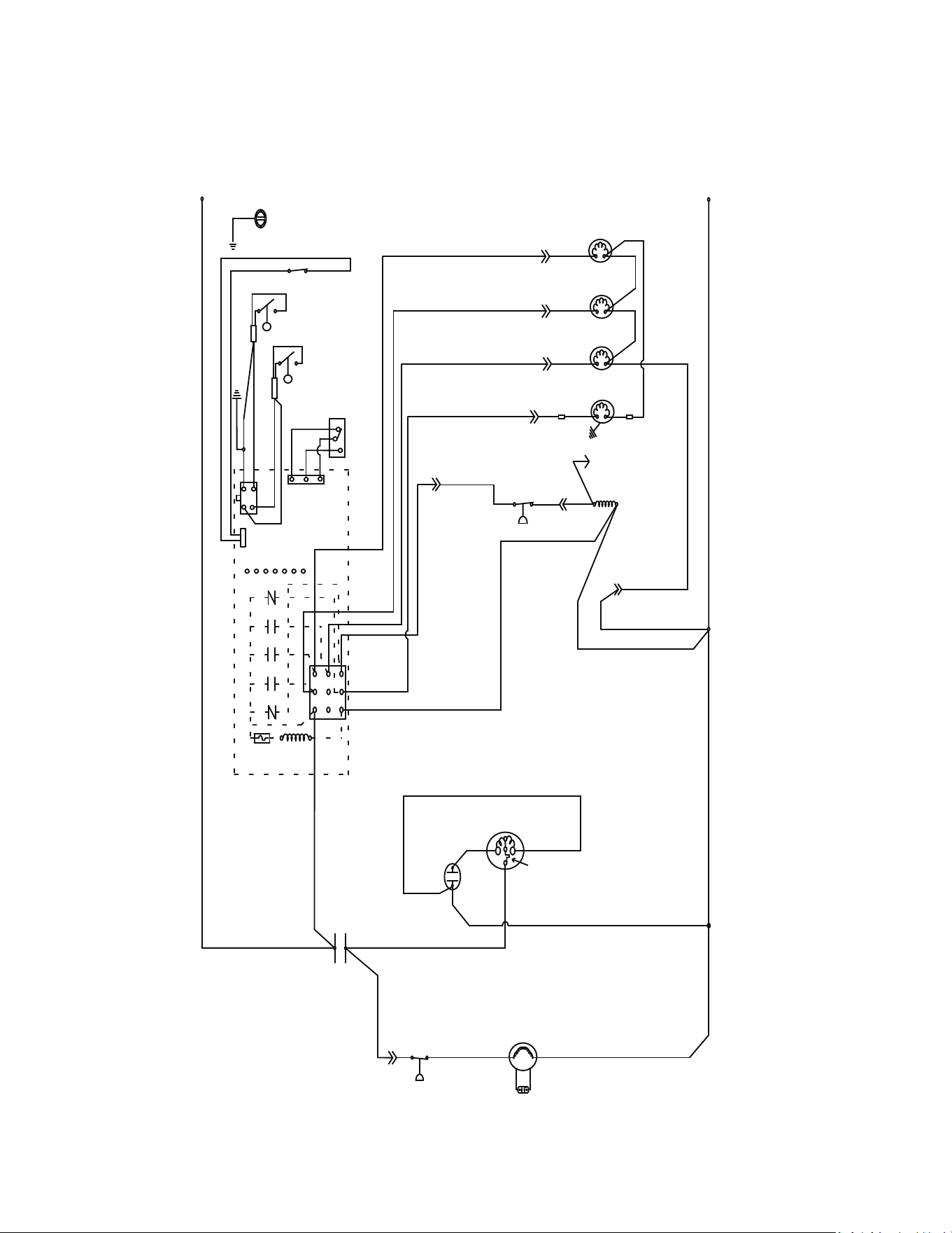
238 - Modular Part Number 000018624 Rev 00 4/26
K0250, KT0300, K0350, KT400, K0420, KT0420, K0500,
K0600, KT0700, K1000, KT1000
WITHOUT PTCR
1 PH SELFCONTAINED AIR/WATERCOOLED
L1
L2
GND
(22)
WHT
(21) BLU
(20) WHT
(99)
WHT
(77) RED
(61) RED
(80)
WHT
(81)
WHT
(76) BLK
(98) GRY
(60) BLK
(57) GRY
(59) ORG
(42)
ORG
(89)
PRPL
(88) PRPL
(58)
PRPL
(56)
WHT
(74)
WHT
(75)
WHT
(50) BLU
(C)
(S)
(R)
(47)
YEL
(47)
RED
(48) BLK
(55)
BLK
L1
(51)
ORG
(85)
BLK
000010656_04
5
14
56
1
55
17
31
26
3
40
41
19
28 54
18
15
7
11
58
42
25
27
Part Number 000018624 Rev 00 4/26 Modular - 239
K0250, KT0300, K0350, KT400, K0420, KT0420, K0500,
K0600, KT0700, K1000, KT1000
Without PTCR
1 Ph Self-contained Air/Water-cooled
Number Component
3 Bin Switch
5 Compressor
7 Compressor Overload
11 Compressor Run Capacitor
14 Condenser Fan Motor
15 Condenser Fan Motor Run Capacitor
17 Contactor Coil
18 Contactor Contacts
19 Control Board
25 Fan Cycle Control
26 Harvest Float Switch
27 Water Level Float Switch
28 Fuse
31 High Pressure Cutout
40 On/Off/Clean Switch
41 See Control Board Schematic For Detail
42 Solenoid Valve - Harvest
54 Transformer
55 Water Dump Valve
56 Water Inlet Valve
58 Water Pump
Wire Colors
BLK Black
BLU Blue
BRN Brown
GRY Grey
ORG Orange
PRPL Purple
RED Red
WHT White
YEL Yellow
Refer to control board schematic for control board detail
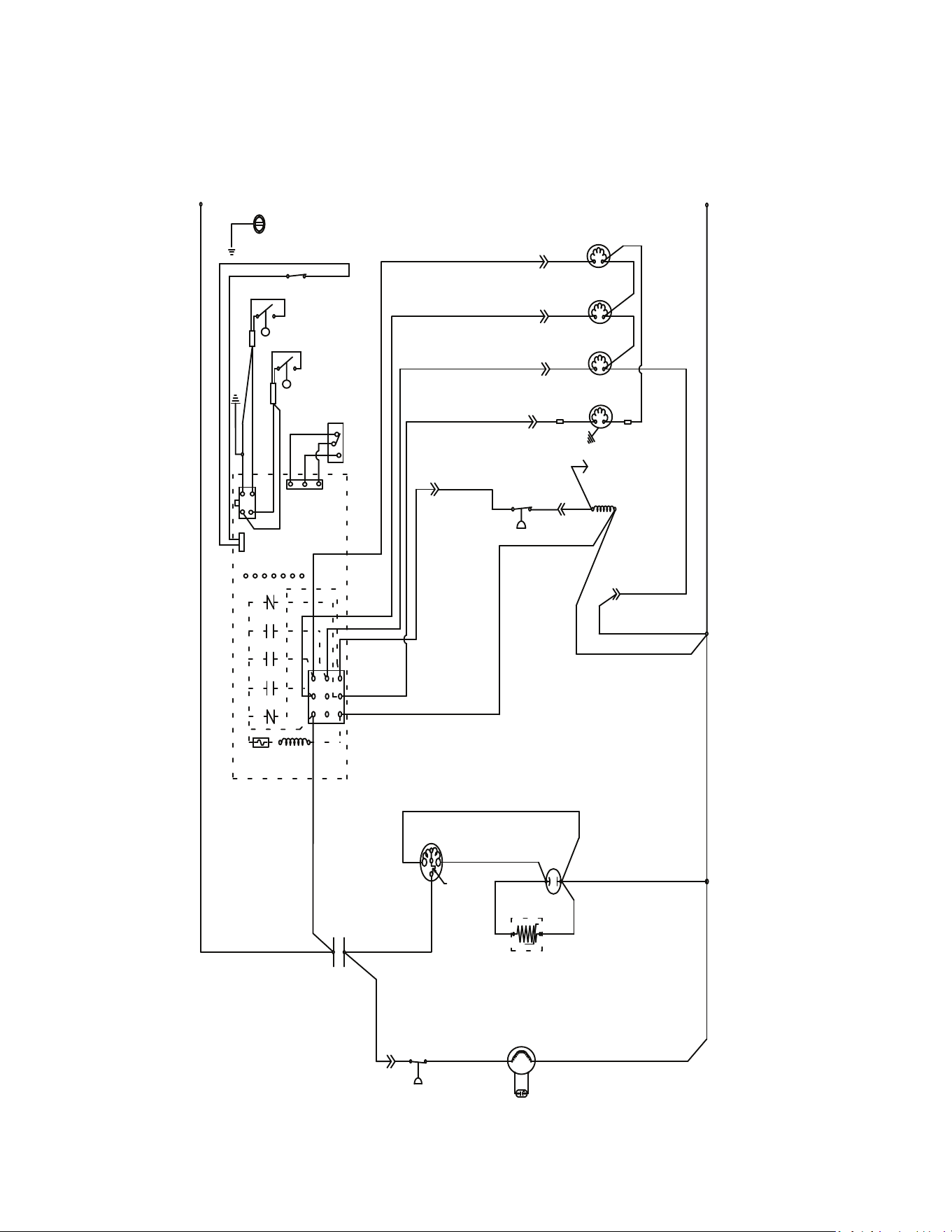
240 - Modular Part Number 000018624 Rev 00 4/26
K0250, KT0300, K0350, KT400, K0420, KT0420, K0500,
KT0500, KT0700, K1000, KT1000
WITH PTCR
1 PH SELFCONTAINED AIR/WATERCOOLED
L1
L2
GND
(22)
WHT
(21) BLU
(20) WHT
(99)
WHT
(77) RED
(61) RED
(80)
WHT
(81)
WHT
(76) BLK
(98) GRY
(60) BLK
(57) GRY
(59) ORG
(42)
ORG
(89)
PRPL
(88) PRPL
(58)
PRPL
(56)
WHT
(74)
WHT
(75)
WHT
(50) BLU
(C)
(S)(R)
(47) YEL
(49) RED
(48) BLK
(55)
BLK
L1
(51)
ORG
(85)
BLK
000014012_00
(45) YEL
(47) ORG
5
14
56
1
55
17
31
26
3
40
41
19
28 54
18
15
7
11
58
42
25
27
9
Part Number 000018624 Rev 00 4/26 Modular - 241
K0250, KT0300, K0350, KT400, K0420, KT0420, K0500,
KT0500, KT0700, K1000, KT1000
WITH PTCR
1 Ph Self-contained Air/Water-cooled
Number Component
3 Bin Switch
5 Compressor
7 Compressor Overload
9 Compressor PTCR
11 Compressor Run Capacitor
14 Condenser Fan Motor
15 Condenser Fan Motor Run Capacitor
17 Contactor Coil
18 Contactor Contacts
19 Control Board
25 Fan Cycle Control
26 Harvest Float Switch
27 Water Level Float Switch
28 Fuse
31 High Pressure Cutout
40 On/Off/Clean Switch
41 See Control Board Schematic For Detail
42 Solenoid Valve - Harvest
54 Transformer
55 Water Dump Valve
56 Water Inlet Valve
58 Water Pump
Wire Colors
BLK Black
BLU Blue
BRN Brown
GRY Grey
ORG Orange
PRPL Purple
RED Red
WHT White
YEL Yellow
Refer to control board schematic for control board detail
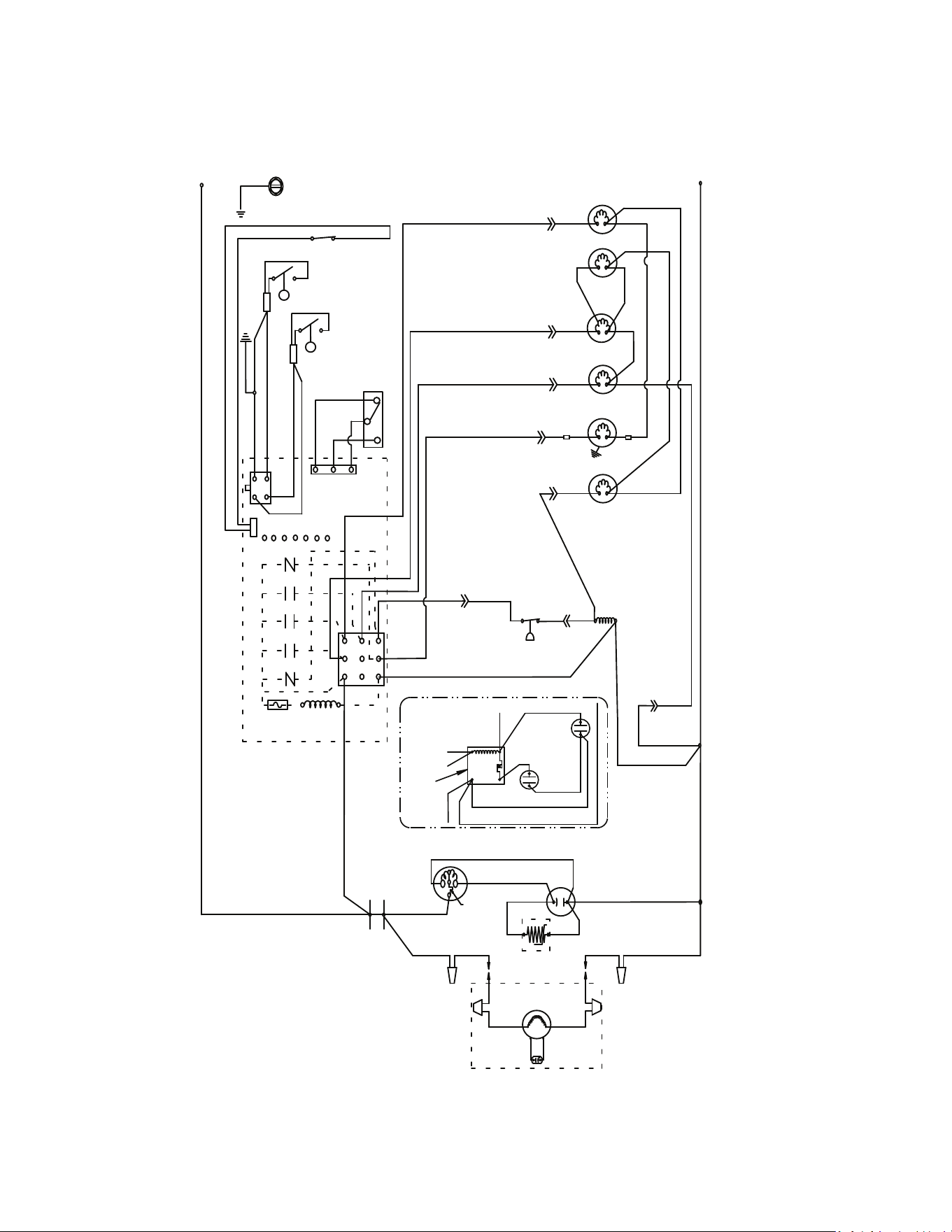
242 - Modular Part Number 000018624 Rev 00 4/26
K1000, KT1000
1PH REMOTE AIRCOOLED CONDENSER
(22)
WHT
(21) BLU
(20) BLU
(99)
WHT
(77) RED
(61) RED
(79)
WHT
(81)
WHT
(76) BLK
(98) GRY
(60) BLK
(57) GRY
(59) ORG
(42)
ORG
(89)
PRPL
(88) PRPL
(58)
PRPL
(56) WHT
(74)
WHT
(75)
WHT
(50) BLU
(C)
(S)
(R)
(45)YEL
RED
(48) BLK
(55)
BLK
L1
(51)
ORG
F1
000011562_04
YEL
(83) ORG
(81 )
WHT
(78) RED
(82)
WHT
(80)
WHT
F2
L1
L2
GND
5
14
56
42
55
17
31
26
3
40
41
19
28 54
9
18
15
7
11
58
44
27
45
5
4
2
1
(49)
RED
(46) BLK
(50) BLU
(45) YEL
(52) BLU
(44) ORG
(53) RED
(47) YEL
(48) BLK
8
11
12
Part Number 000018624 Rev 00 4/26 Modular - 243
K1000, KT1000
1Ph Remote Air-cooled Condenser
Number Component
3 Bin Switch
5 Compressor
7 Compressor Overload
8 Compressor Potential Relay - When Used
9 Compressor PTCR - When Used
11 Compressor Run Capacitor
12 Compressor Start Capacitor - When Used
14 Condenser Fan Motor
15 Condenser Fan Motor Run Capacitor
17 Contactor Coil
18 Contactor Contacts
19 Control Board
26 Harvest Float Switch
27 Water Level Float Switch
28 Fuse
31 High Pressure Cutout
40 On/Off/Clean Switch
41 See Control Board Schematic For Detail
42 Solenoid Valve - Harvest
44 Solenoid Valve - Harvest Pressure Regulating
45 Solenoid Valve - Liquid Line Solenoid
54 Transformer
55 Water Dump Valve
56 Water Inlet Valve
58 Water Pump
Wire Colors
BLK Black
BLU Blue
BRN Brown
GRY Grey
ORG Orange
PRPL Purple
RED Red
WHT White
YEL Yellow
Refer to control board schematic for control board detail
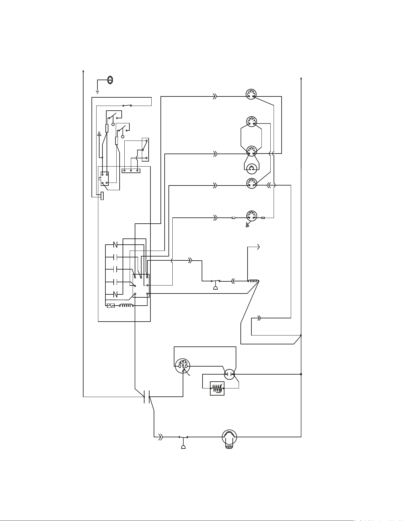
244 - Modular Part Number 000018624 Rev 00 4/26
K1350, KT1700, K1800
1 PH SELFCONTAINED AIR/WATERCOOLED
L1
L2
GND
(22)
WHT
(21) BLU
(20) BLU
(99)
WHT
(77) RED
(61) RED
(87)
WHT
(81) WHT
(25) RED
(76) BLK
(60) BLK
(57) GRY
(42)
ORG
(89)
PRPL
(88) PRPL
(58)
PRPL
(56) WHT
(74)
WHT
(75)WHT
(50) BLU
(C)
(S)
(R)
(45)YEL
RED
BLK
(55)
BLK
L1
(51)
ORG
000012160_04
YEL
(83) ORG
(81 )
WHT
(88) RED
(80)
WHT
(59)
ORG
(26)
WHT
(98) GRY
(85)
BLK
RED
BLK
WHT
BRN
5
14
56
1
42
55
17
31
26
3
40
41
19
28 54
9
18
15
7
11
58
43
25
27
Part Number 000018624 Rev 00 4/26 Modular - 245
K1350, KT1700, K1800
1 Ph Self-contained Air/Water-cooled
Number Component
1 Air Pump Harvest Assist
3 Bin Switch
5 Compressor
7 Compressor Overload
9 Compressor PTCR
11 Compressor Run Capacitor
14 Condenser Fan Motor
15 Condenser Fan Motor Run Capacitor
17 Contactor Coil
18 Contactor Contacts
19 Control Board
25 Fan Cycle Control
26 Harvest Float Switch
27 Water Level Float Switch
28 Fuse
31 High Pressure Cutout
40 On/Off/Clean Switch
41 See Control Board Schematic For Detail
42 Solenoid Valve - Harvest Left Hand
43 Solenoid Valve - Harvest Right Hand
54 Transformer
55 Water Dump Valve
56 Water Inlet Valve
58 Water Pump
Wire Colors
BLK Black
BLU Blue
BRN Brown
GRY Grey
ORG Orange
PRPL Purple
RED Red
WHT White
YEL Yellow
Refer to control board schematic for control board detail
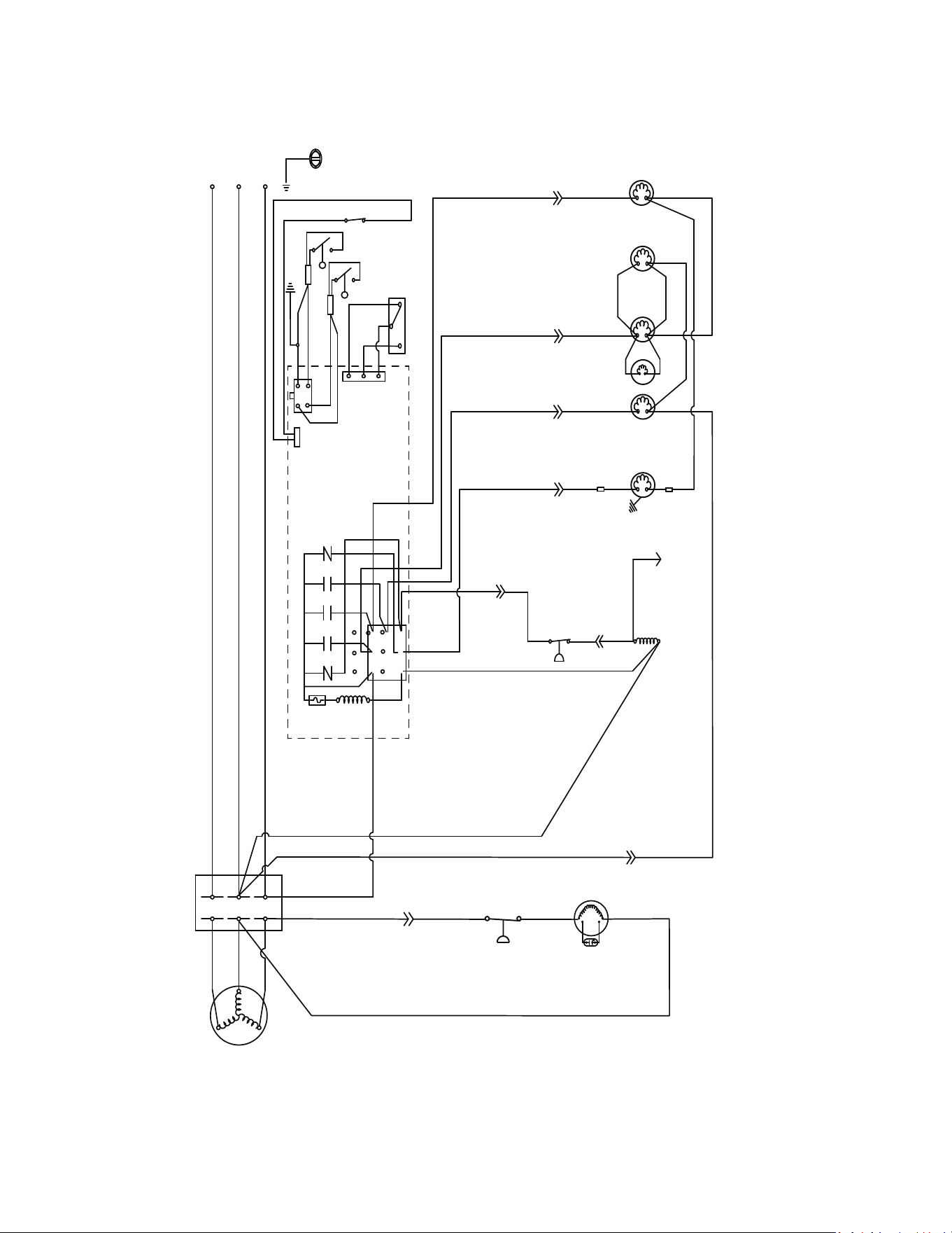
246 - Modular Part Number 000018624 Rev 00 4/26
K1350, KT1700, K1800
3 PH SELFCONTAINED AIR/WATERCOOLED
L1
GND
(22) WHT
(21) BLU
(20) BLU
(99)
WHT
(77) RED
(61) RED
(87)
WHT
(81) WHT
(25) RED
(76) BLK
(60) BLK
(57) GRY
(42)
ORG
(89)
PRPL
(88) PRPL
(58)
PRPL
(56) WHT
(74)
WHT
(75)WHT
(85) BLK
(55)
BLK
L1
000012160_04
(88) RED
(80)
WHT
(59)
ORG
(26)
WHT
(98) GRY
RED
BLK
WHT
BRN
L3
L2
(51) ORG
L2L3
5
(81)
WHT
14
56
1
42
55
17
31
26
3
40
41
19
28 54
15
58
43
27
18
25
Part Number 000018624 Rev 00 4/26 Modular - 247
K1350, KT1700, K1800
3 Ph Self-contained Air/Water-cooled
Number Component
1 Air Pump Harvest Assist
3 Bin Switch
5 Compressor
7 Compressor Overload
14 Condenser Fan Motor
15 Condenser Fan Motor Run Capacitor
17 Contactor Coil
18 Contactor Contacts
19 Control Board
25 Fan Cycle Control
26 Harvest Float Switch
27 Water Level Float Switch
28 Fuse
31 High Pressure Cutout
40 On/Off/Clean Switch
41 See Control Board Schematic For Detail
42 Solenoid Valve - Harvest Left Hand
43 Solenoid Valve - Harvest Right Hand
54 Transformer
55 Water Dump Valve
56 Water Inlet Valve
58 Water Pump
56 Water Inlet Valve
58 Water Pump
Wire Colors
BLK Black
BLU Blue
BRN Brown
GRY Grey
ORG Orange
PRPL Purple
RED Red
WHT White
YEL Yellow
Refer to control board schematic for control board detail
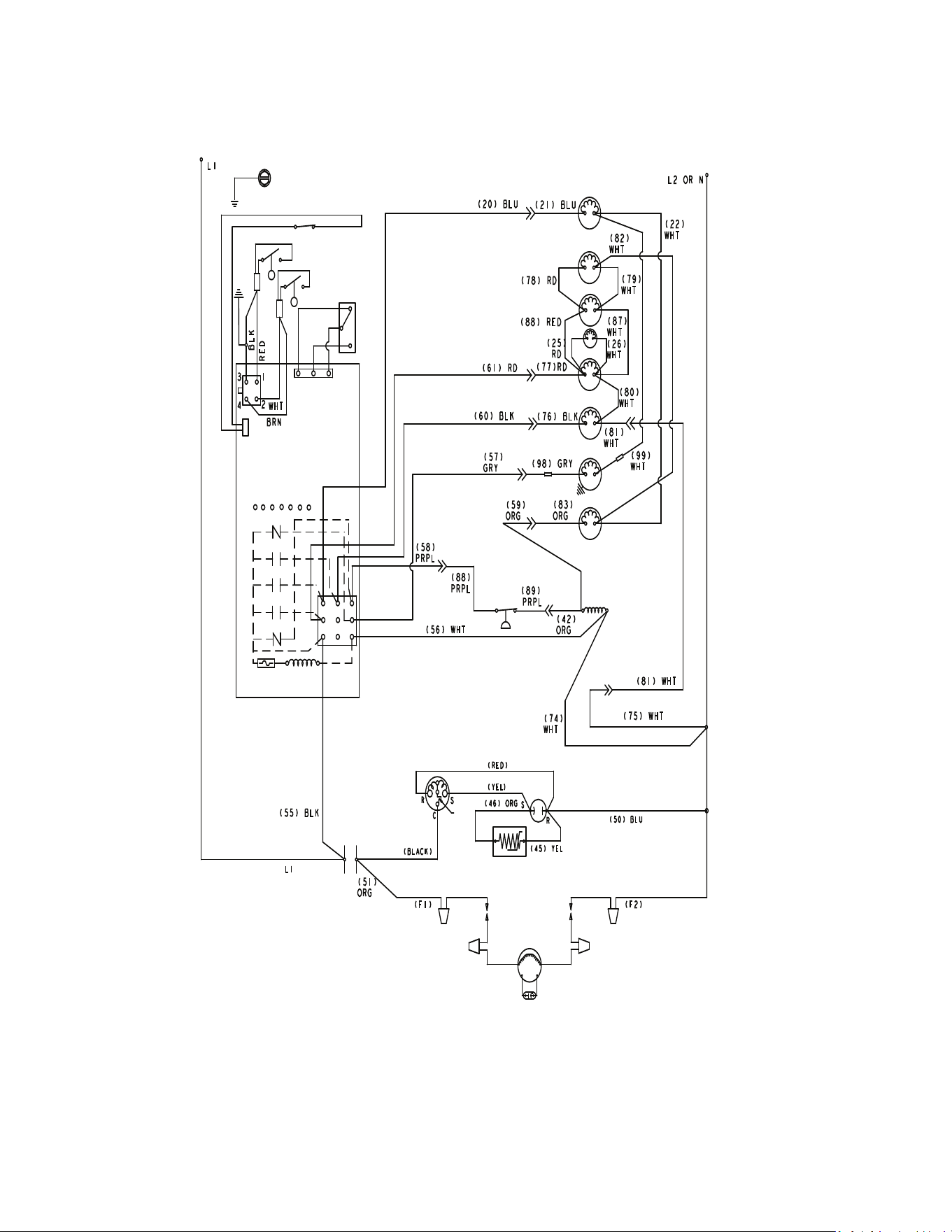
248 - Modular Part Number 000018624 Rev 00 4/26
K1350, KT1700, K1800
1PH REMOTE AIRCOOLED CONDENSER
000012161_04
3
26
27
18
5
7
11
9
14
15
17
31
45
58
55
42
1
43
44
56
19
28 54
40
Part Number 000018624 Rev 00 4/26 Modular - 249
K1350, KT1700, K1800
1Ph Remote Air-cooled Condenser
Number Component
1 Air Pump Harvest Assist
3 Bin Switch
5 Compressor
7 Compressor Overload
9 Compressor PTCR
11 Compressor Run Capacitor
14 Condenser Fan Motor
15 Condenser Fan Motor Run Capacitor
17 Contactor Coil
18 Contactor Contacts
19 Control Board
25 Fan Cycle Control
26 Harvest Float Switch
27 Water Level Float Switch
28 Fuse
31 High Pressure Cutout
40 On/Off/Clean Switch
41 See Control Board Schematic For Detail
42 Solenoid Valve - Harvest Left Hand
43 Solenoid Valve - Harvest Right Hand
44 Solenoid Valve - Harvest Pressure Regulating
45 Solenoid Valve - Liquid Line
54 Transformer
55 Water Dump Valve
56 Water Inlet Valve
58 Water Pump
Wire Colors
BLK Black
BLU Blue
BRN Brown
GRY Grey
ORG Orange
PRPL Purple
RED Red
WHT White
YEL Yellow
Refer to control board schematic for control board detail
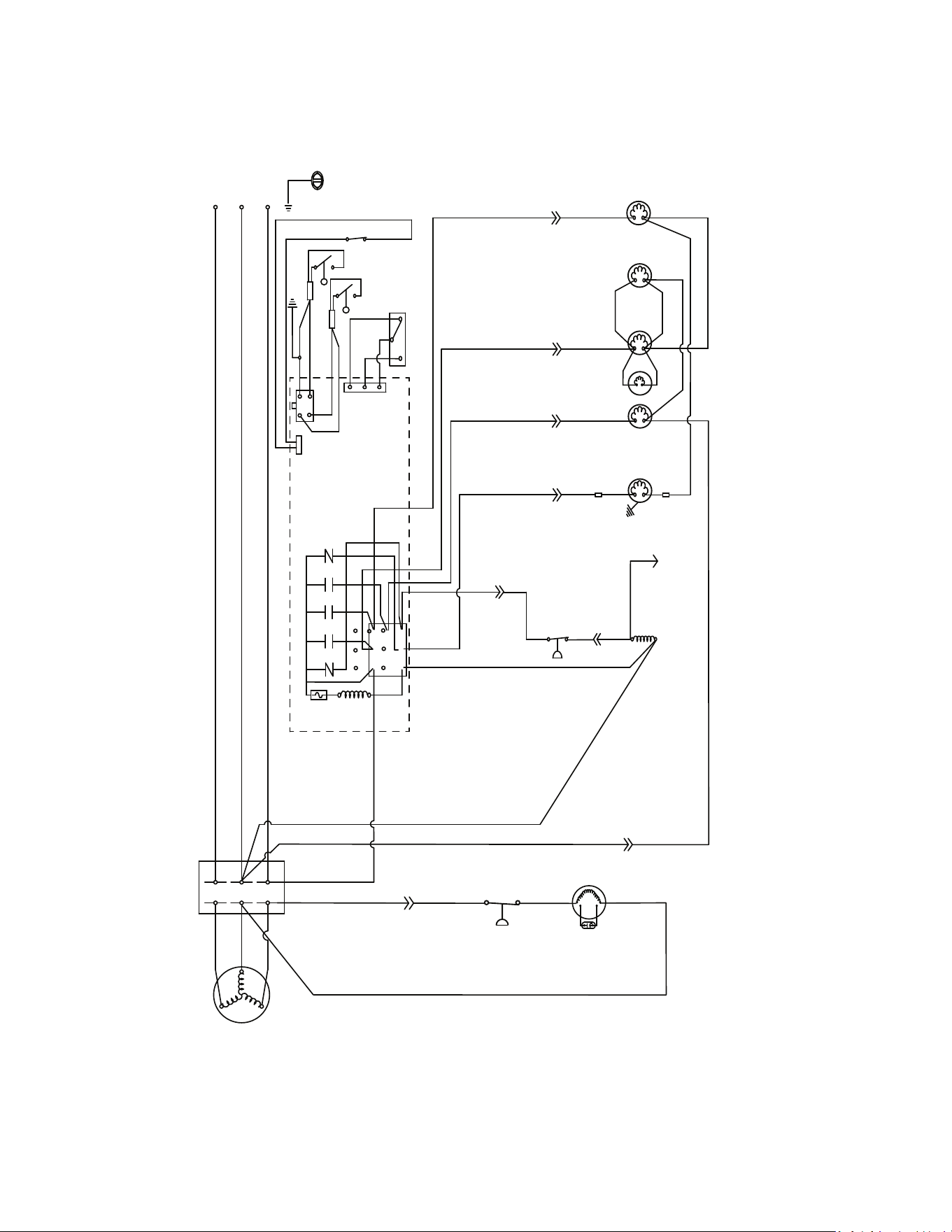
250 - Modular Part Number 000018624 Rev 00 4/26
K1350, KT1700, K1800
3 PH REMOTE AIRCOOLED CONDENSER
L1
GND
(22) WHT
(21) BLU
(20) BLU
(99)
WHT
(77) RED
(61) RED
(87)
WHT
(81) WHT
(25) RED
(76) BLK
(60) BLK
(57) GRY
(42)
ORG
(89)
PRPL
(88) PRPL
(58)
PRPL
(56) WHT
(74)
WHT
(75)WHT
(85) BLK
(55)
BLK
L1
000012160_04
(88) RED
(80)
WHT
(59)
ORG
(26)
WHT
(98) GRY
RED
BLK
WHT
BRN
L3
L2
(51) ORG
L2L3
5
(81)
WHT
14
56
1
42
55
17
31
26
3
40
41
19
28 54
15
58
43
27
18
25
Part Number 000018624 Rev 00 4/26 Modular - 251
K1350, KT1700, K1800
3 Ph Remote Air-cooled Condenser
Number Component
1 Air Pump Harvest Assist
3 Bin Switch
5 Compressor
14 Condenser Fan Motor
15 Condenser Fan Motor Run Capacitor
17 Contactor Coil
18 Contactor Contacts
19 Control Board
25 Fan Cycle Control
26 Harvest Float Switch
27 Water Level Float Switch
28 Fuse
31 High Pressure Cutout
40 On/Off/Clean Switch
41 See Control Board Schematic For Detail
42 Solenoid Valve - Harvest Left Hand
43 Solenoid Valve - Harvest Right Hand
44 Solenoid Valve - Harvest Pressure Regulating
45 Solenoid Valve - Liquid Line
54 Transformer
55 Water Dump Valve
56 Water Inlet Valve
58 Water Pump
Wire Colors
BLK Black
BLU Blue
BRN Brown
GRY Grey
ORG Orange
PRPL Purple
RED Red
WHT White
YEL Yellow
Refer to control board schematic for control board detail
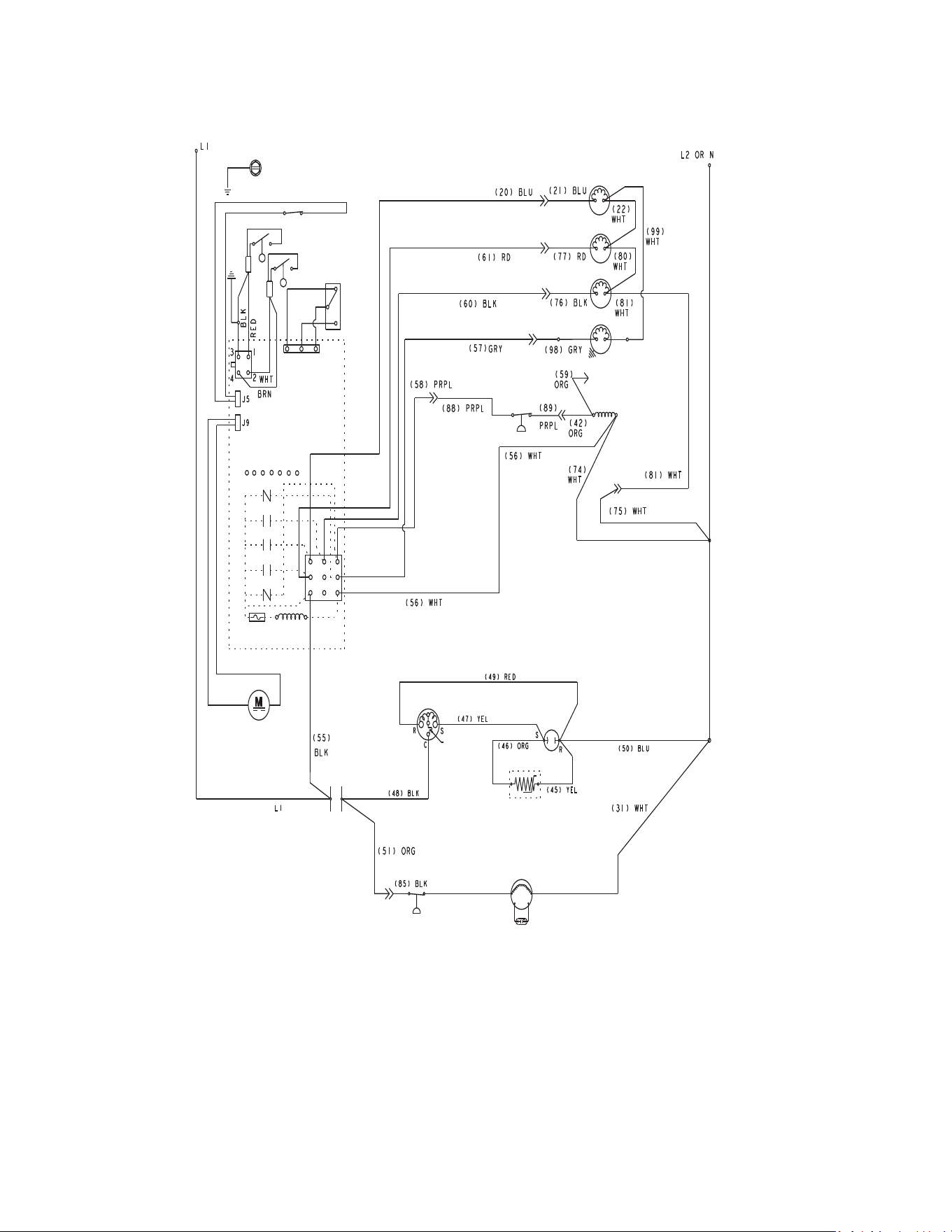
252 - Modular Part Number 000018624 Rev 00 4/26
KP0300/KP0400/KP0500/KP0700/KP1000
1 Ph Self-contained Air/Water-cooled
5
14
56
55
17
31
26
3
40
41
19
28
54
18
15
7
11
58
42
25
62
27
9
Part Number 000018624 Rev 00 4/26 Modular - 253
KP0300/KP0400/KP0500/KP0700/KP1000
1 Ph Self-contained Air/Water-cooled
Number Component
3 Bin Switch
5 Compressor
7 Compressor Overload
9 Compressor PTCR (when used)
11 Compressor Run Capacitor
14 Condenser Fan Motor
15 Condenser Fan Motor Run Capacitor
17 Contactor Coil
18 Contactor Contacts
19 Control Board
25 Fan Cycle Control
26 Harvest Float Switch
27 Water Level Float Switch
28 Fuse
31 High Pressure Cutout
40 On/Off/Clean Switch
41 See Control Board Schematic For Detail
42 Solenoid Valve - Harvest
54 Transformer
55 Water Dump Valve
56 Water Inlet Valve
58 Water Pump
62 Vent Fan (when used)
Wire Colors
BLK Black
BLU Blue
BRN Brown
GRY Grey
ORG Orange
PRPL Purple
RED Red
WHT White
YEL Yellow
Refer to control board schematic for control board detail
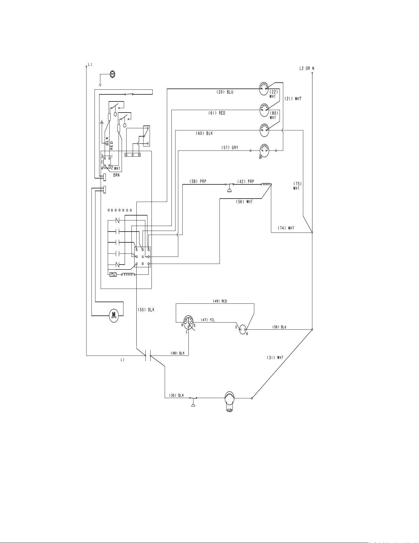
254 - Modular Part Number 000018624 Rev 00 4/26
KP0420
1 Ph Self-contained Air/Water-cooled
5
14
56
55
17
31
26
3
40
41
19
28
54
18
15
7
11
58
42
25
62
27
Part Number 000018624 Rev 00 4/26 Modular - 255
KP0420
1 Ph Self-contained Air/Water-cooled
Number Component
3 Bin Switch
5 Compressor
7 Compressor Overload
11 Compressor Run Capacitor
14 Condenser Fan Motor
15 Condenser Fan Motor Run Capacitor
17 Contactor Coil
18 Contactor Contacts
19 Control Board
25 Fan Cycle Control
26 Harvest Float Switch
27 Water Level Float Switch
28 Fuse
31 High Pressure Cutout
40 On/Off/Clean Switch
41 See Control Board Schematic For Detail
42 Solenoid Valve - Harvest
54 Transformer
55 Water Dump Valve
56 Water Inlet Valve
58 Water Pump
62 Vent Fan (when used)
Wire Colors
BLK Black
BLU Blue
BRN Brown
GRY Grey
ORG Orange
PRPL Purple
RED Red
WHT White
YEL Yellow
Refer to control board schematic for control board detail
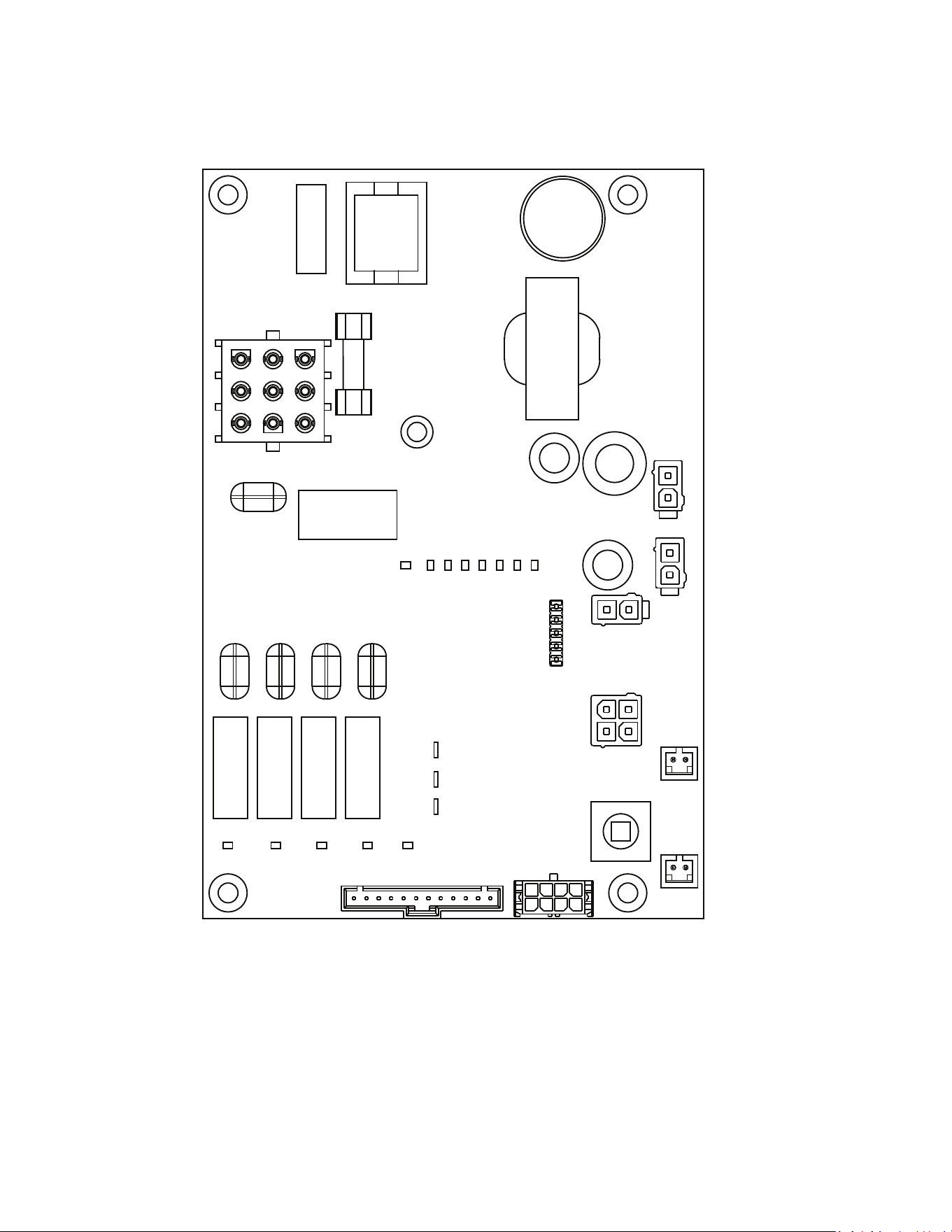
256 - Modular Part Number 000018624 Rev 00 4/26
Electronic Control Board
KP & KT MODELS
1
2
3
4
5
678
9
10
11
12
13
14
15
16
17
19
18
20
21
23
24
25
22
Part Number 000018624 Rev 00 4/26 Modular - 257
Electronic Control Board
Number Component
1 LED Water Pump Relay
2 LED Compressor Relay
3 LED Water Dump Valve Relay
4 LED Harvest Solenoid Valve
5 LED Clean
6 Thermistor
7 Thermistor
8 Thermistor
9 LED Water Fill Valve
10 LED Harvest Float
11 LED Water Level Float
12 LED Bin Switch
13 LED Safety Limit 2
14 LED Safety Limit 1
15 LED Harvest
16 LED Test Mode
17 Fuse
18 Motor Connector
19 EC Fan Motor Connector
20 Bin Switch Connector
21 Float Switch Water Level
22 Float Switch Harvest
23 Thermistor 2
24 Test Switch
25 Thermistor 1
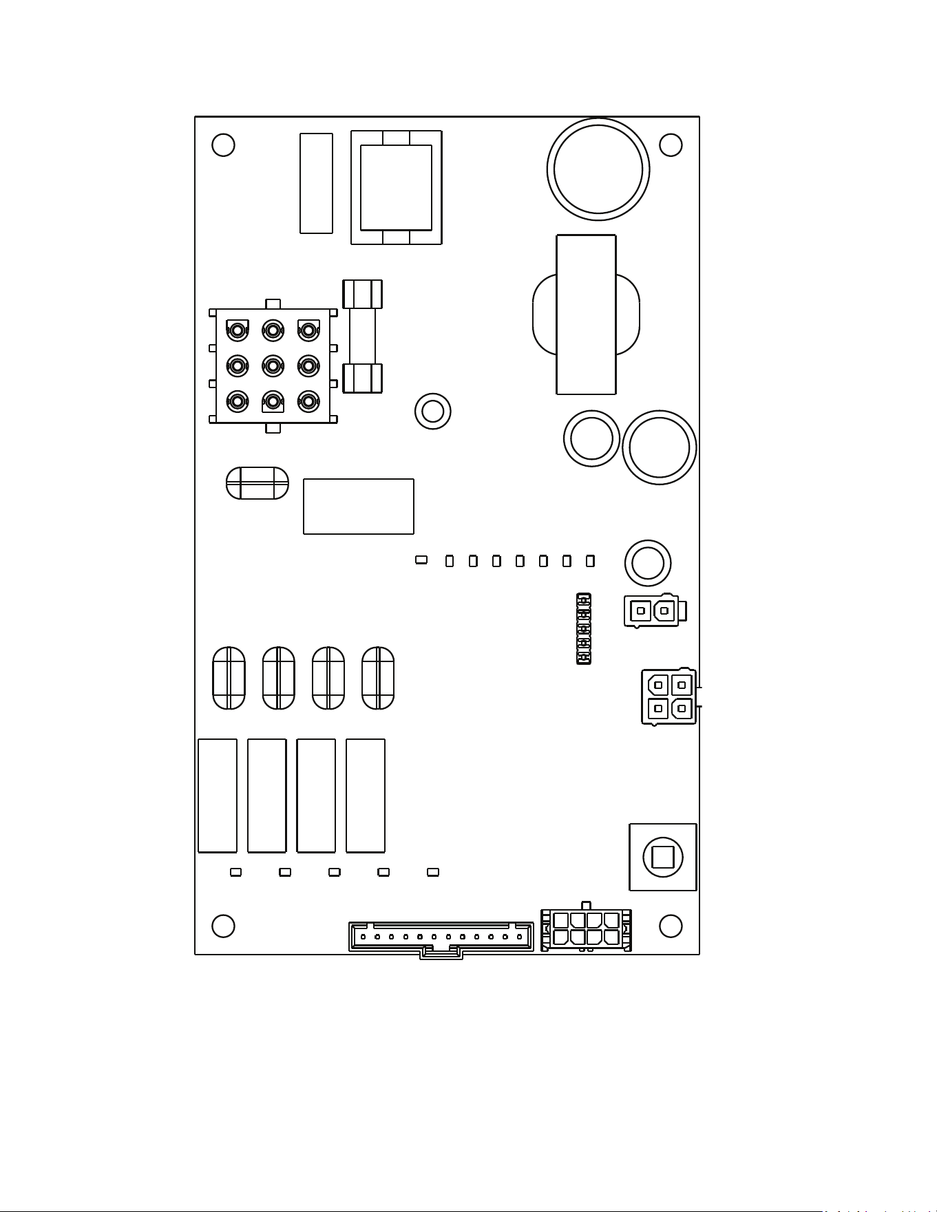
258 - Modular Part Number 000018624 Rev 00 4/26
K MODELS
1
2
3
4
5
9
10
11
12
13
14
15
16
17
20
21
24
22
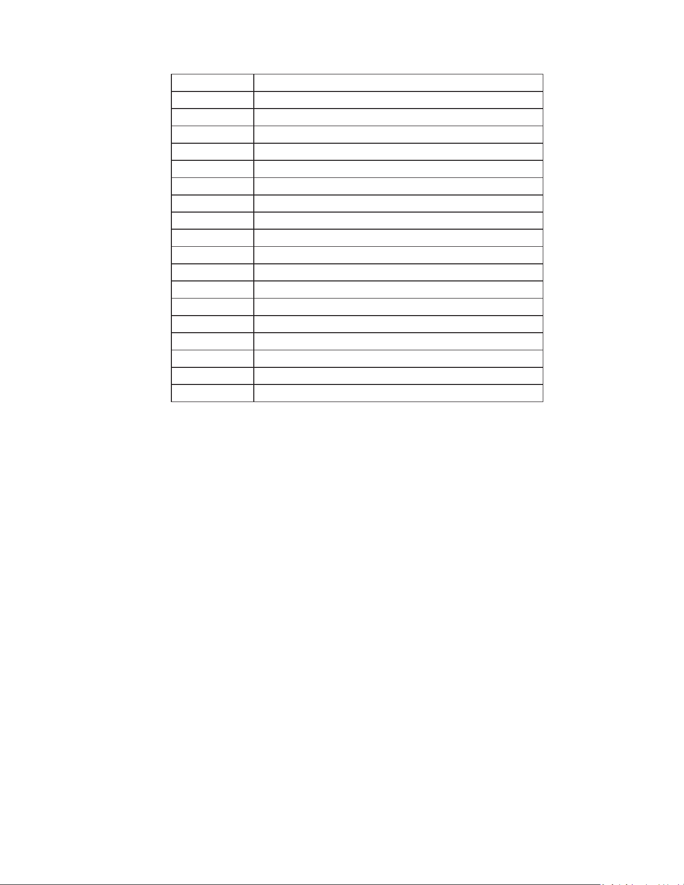
Part Number 000018624 Rev 00 4/26 Modular - 259
Electronic Control Board
Number Component
1 LED Water Pump Relay
2 LED Compressor Relay
3 LED Water Dump Valve Relay
4 LED Harvest Solenoid Valve
5 LED Clean
9 LED Water Fill Valve
10 LED Harvest Float
11 LED Water Level Float
12 LED Bin Switch
13 LED Safety Limit 2
14 LED Safety Limit 1
15 LED Harvest
16 LED Test Mode
17 Fuse 3.15 Amp
20 Bin Switch Connector
21 Float Switch Water Level
22 Float Switch Harvest
24 Test Switch
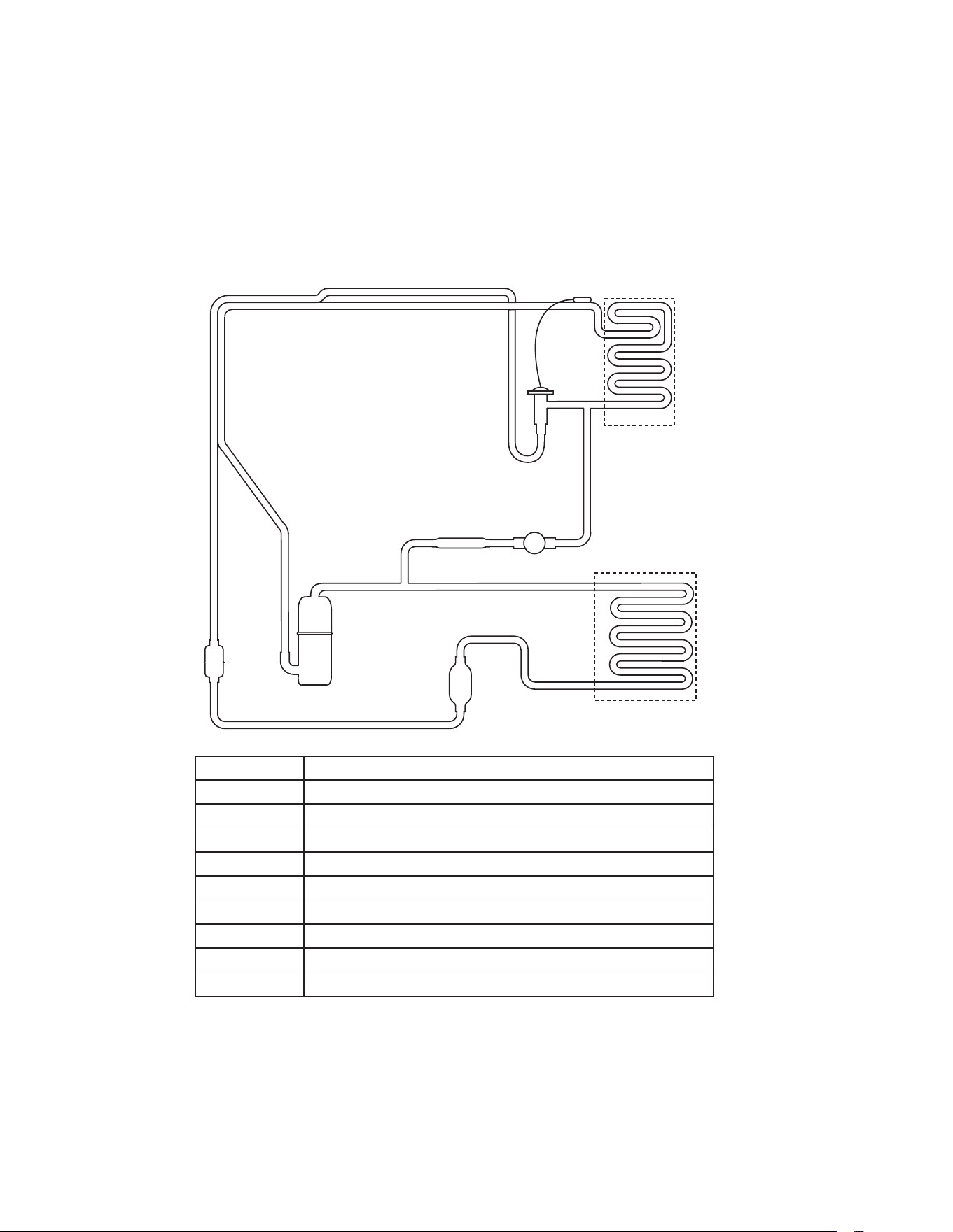
260 - Modular Part Number 000018624 Rev 00 4/26
Refrigeration Tubing Schematics
SELFCONTAINED AIR OR WATERCOOLED
K0250, K0350, K0420, K0500, K0600, K1000
KP0300, KP0400, KP0420, KP0500, KP0700, KP1000
KT0300, KT0400, KT0420, KT0500, KT0700, KT1000
Number Component
1 Compressor
2 Condenser-Air or Water-cooled
3 Receiver - Water-cooled Only
4 Liquid Line Filter Drier
5 Heat Exchanger
6 TXV - Thermostatic Expansion Valve
7 Evaporator
8 Strainer
9 Harvest Solenoid Valve
1
2
3
4
5
8
9
6
7
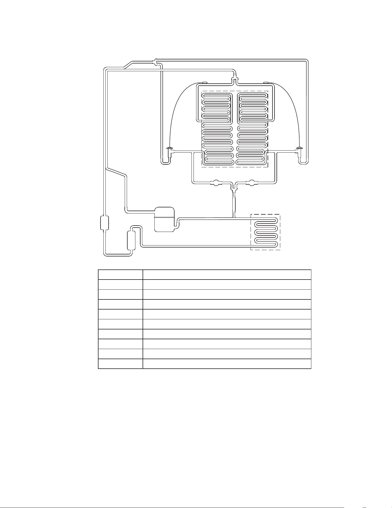
Part Number 000018624 Rev 00 4/26 Modular - 261
K1350, KT1700, K1800
SELFCONTAINED AIR OR WATERCOOLED
Number Component
1 Compressor
2 Condenser-Air or Water-cooled
3 Receiver - Water-cooled Only
4 Liquid Line Filter Drier
5 Heat Exchanger
6 TXV - Thermostatic Expansion Valve
7 Evaporator
8 Strainer
9 Harvest Solenoid Valve
1
2
3
4
5
6
7
8
99
6
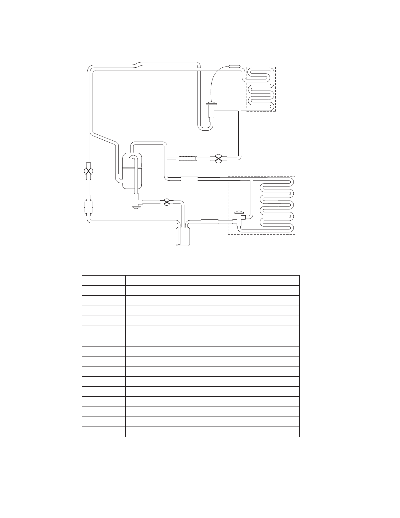
262 - Modular Part Number 000018624 Rev 00 4/26
K1000, KT1000 REMOTE AIRCOOLED CONDENSER
Number Component
1 Compressor
2 Discharge Check Valve
3 Condenser - Remote Air-Cooled
4 Head Pressure Control Valve
5 Liquid Line Check Valve
6 Receiver
7 Liquid Line Filter Drier
8 Liquid Line Solenoid Valve
9 Heat Exchanger
10 TXV - Thermostatic Expansion Valve
11 Evaporator
12 Strainer
13 Harvest Solenoid Valve
14 Harvest Pressure Solenoid Valve
15 Harvest Pressure Regulating Valve
1
23
4
5
8
9
7
10 11
12 13
6
14
15
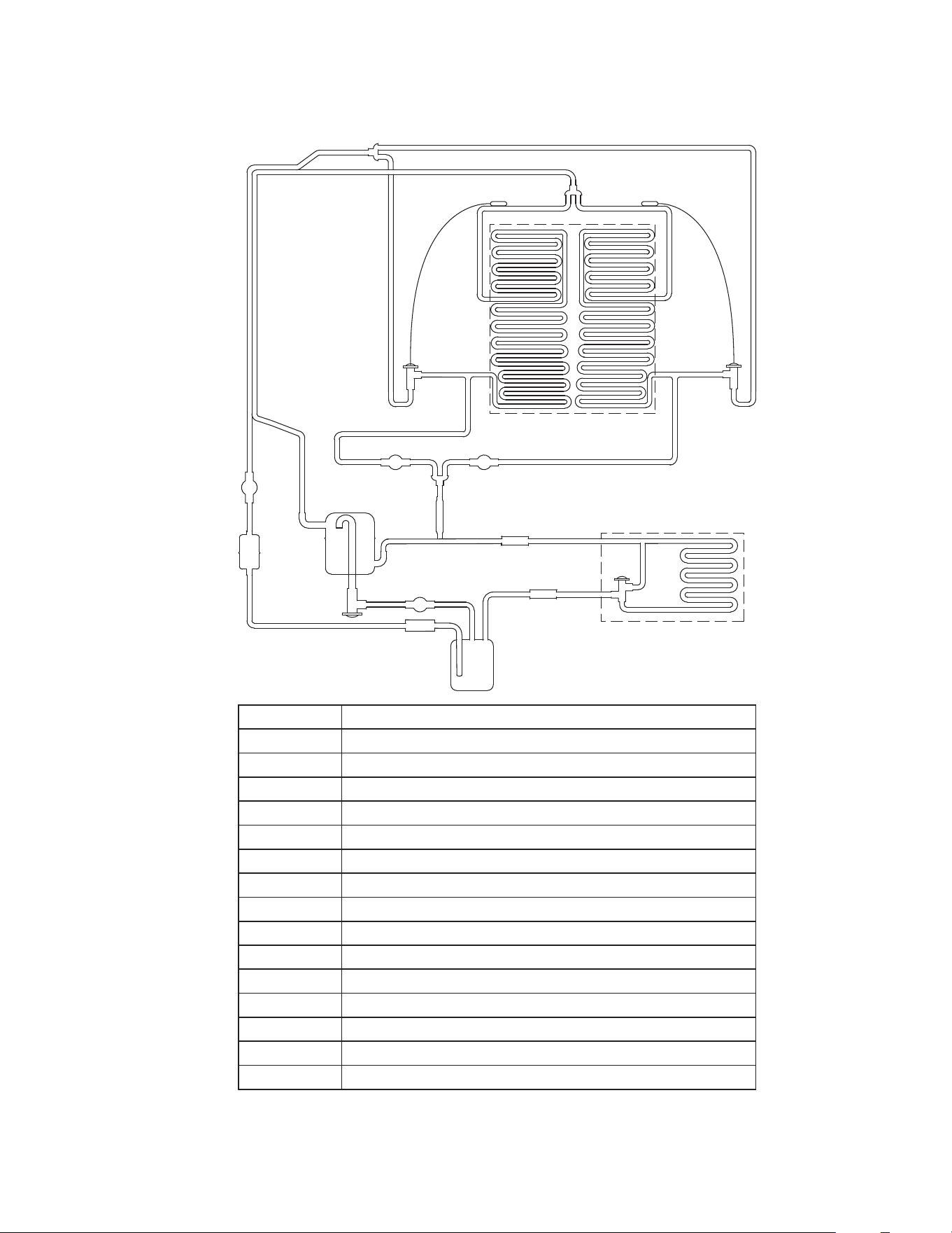
Part Number 000018624 Rev 00 4/26 Modular - 263
K1350, KT1700, K1800
REMOTE AIRCOOLED CONDENSER
Number Component
1 Compressor
2 Discharge Check Valve
3 Condenser - Remote Air-Cooled
4 Head Pressure Control Valve
5 Liquid Line Check Valve
6 Receiver
7 Liquid Line Filter Drier
8 Liquid Line Solenoid Valve
9 Heat Exchanger
10 TXV - Thermostatic Expansion Valve
11 Evaporator
12 Strainer
13 Harvest Solenoid Valve
14 Harvest Pressure Solenoid Valve
15 Harvest Pressure Regulating Valve
1
2
3
4
5
6
7
8
9
10
11
12
13
15
16
10
13
5

THIS PAGE INTENTIONALLY LEFT BLANK

MANITOWOC ICE
2110 SOUTH 26TH STREET
MANITOWOC, WI 54220
8005455720
WWW.KOOLAIRE.COM
Part Number 000018624 Rev 00 4/26
©2026 Manitowoc Ice except where explicitly stated otherwise. All rights reserved.