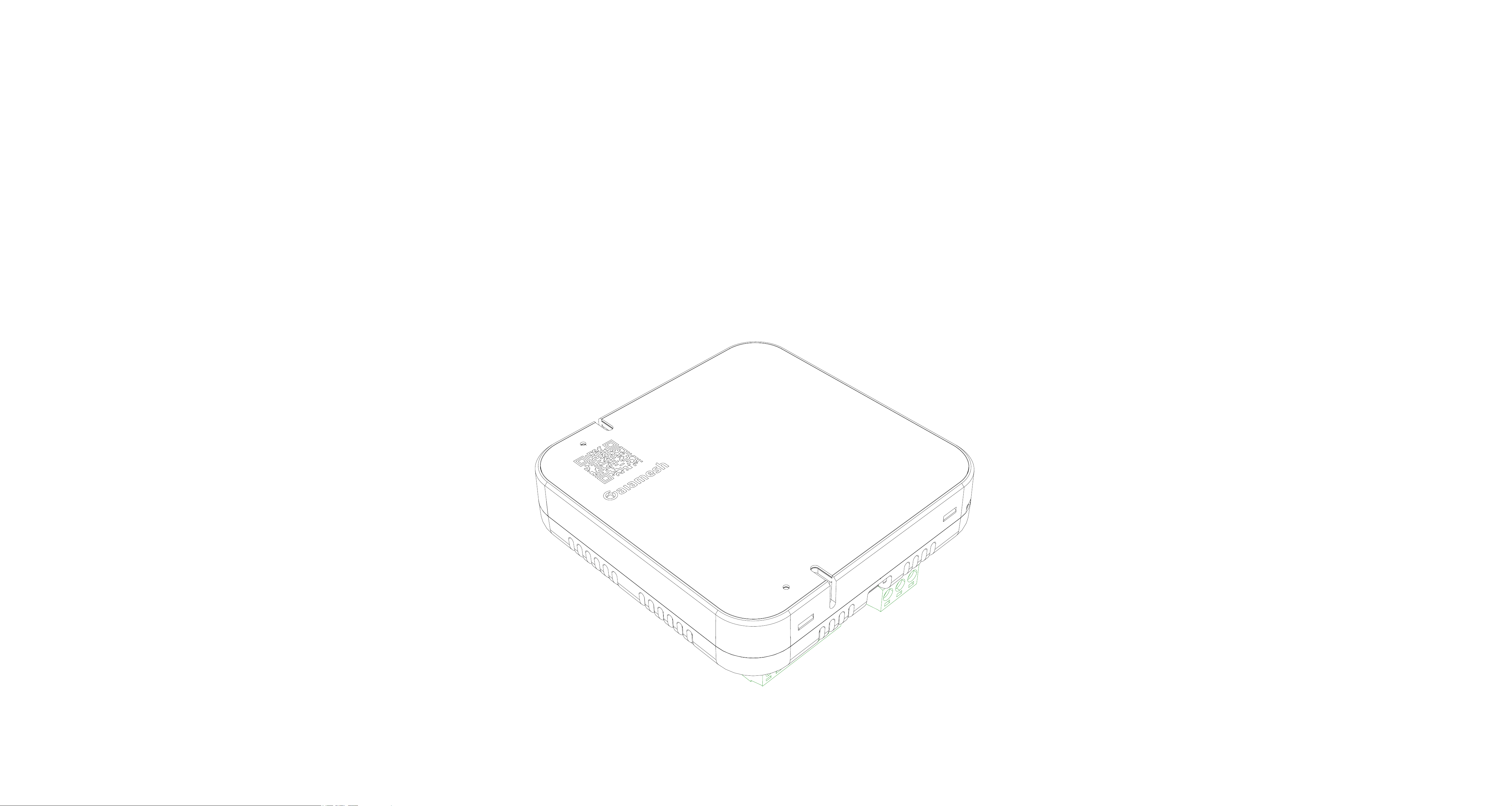
Gaiamesh Integrator v3
Model: GM-IN-3 Abbreviation: IN
Installation Manual

Product introduction
Drawing name
01
Drawing name
Table of contents
Technical specifications
Cover sheet
02
03
No. No.
04
05
Installation method
Table of Contents
P
rod
uc
t
High
l
i
g
hts
Temperature +
humidity sensor
(option)
Wireless connectivity
supports Wifi,
Bluetooth (native)
Po
we
r
outp
u
t – elimi
n
a
t
es
add
i
t
i
o
n
al
c
a
bli
n
g an
d
p
ower su
p
plie
s f
o
r
e
xt
er
n
al
lo
w-
p
ow
e
r de
v
ice
s
Comp
a
c
t size – 86x86x43mm form f
a
ctor
install
s
o
nto stan
d
ard 86
-
box, on the
w
all
or
c
e
il
ing
.
Pluggable connectors
support easy wiring
during installation and
maintenance
RS485 IO for integration
of a wide range of
external devices
Standard anchor holes
for easy installation onto
86-boxes
220V AC power supply
1-Wire IO supporting
multiple external
temperature sensors
(daisy-chained
DS18B20s)
Scan QR
code to
provision
device using
mobile
phone
P
o
wer
f
u
l
Mod
b
u
s
i
n
t
eg
rati
o
n
ca
pab
i
l
i
t
y
– c
an
in
te
g
ra
te a
w
i
de
ra
n
g
e
o
f
d
e
vi
ce
s, wit
h
capac
i
t
y
o
f
u
p
t
o 5
0
0
M
o
d
b
u
s
p
o
ints.
On-boar
d
da
ta
st
o
rage
–
C
a
n
s
to
re
u
p
t
o
2
0
0
K
re
a
d
i
n
g
s
5VDC / 24VDC
output for
powering
external devices
S
imp
l
e
wi
r
eles
s
i
n
s
tall
a
ti
o
n
–
s
i
mp
l
y
replac
e
e
xist
i
n
g
s
w
i
tch
e
s,
no
ad
d
i
t
i
o
n
al
ca
b
l
i
ng
r
e
q
ui
r
e
d.
S
eamles
s
c
ommi
s
sion
i
ng
–
d
e
vice
a
utom
ati
ca
ll
y
j
o
i
ns
w
ir
eles
s
me
sh
an
d
link
s
t
o
c
l
o
ud
up
o
n po
wer-
u
p
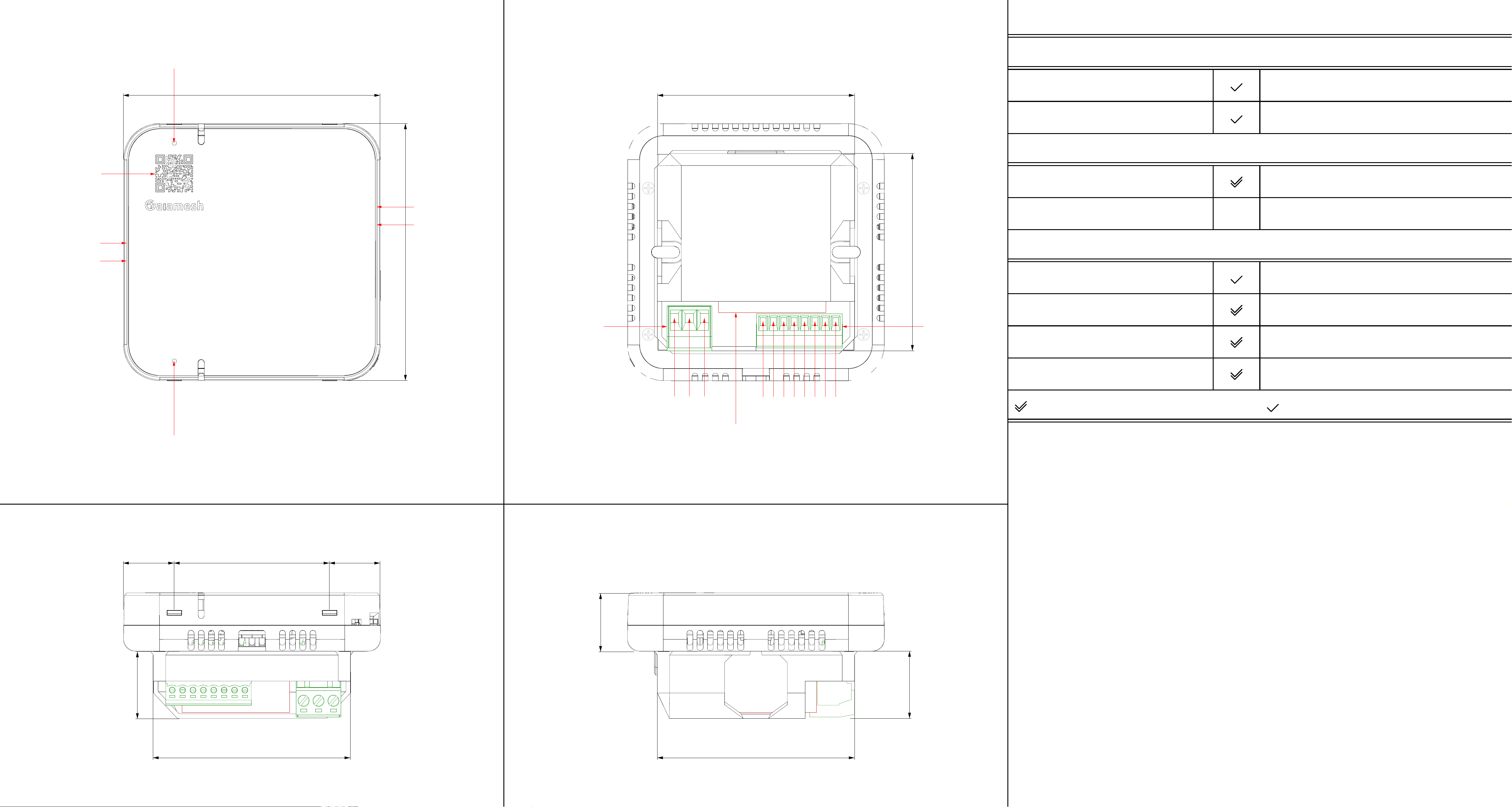
22.50
52.00 17.00
86.00
19.50
66.00
22.50
66.00
66.00
66.00
17.00
86.00
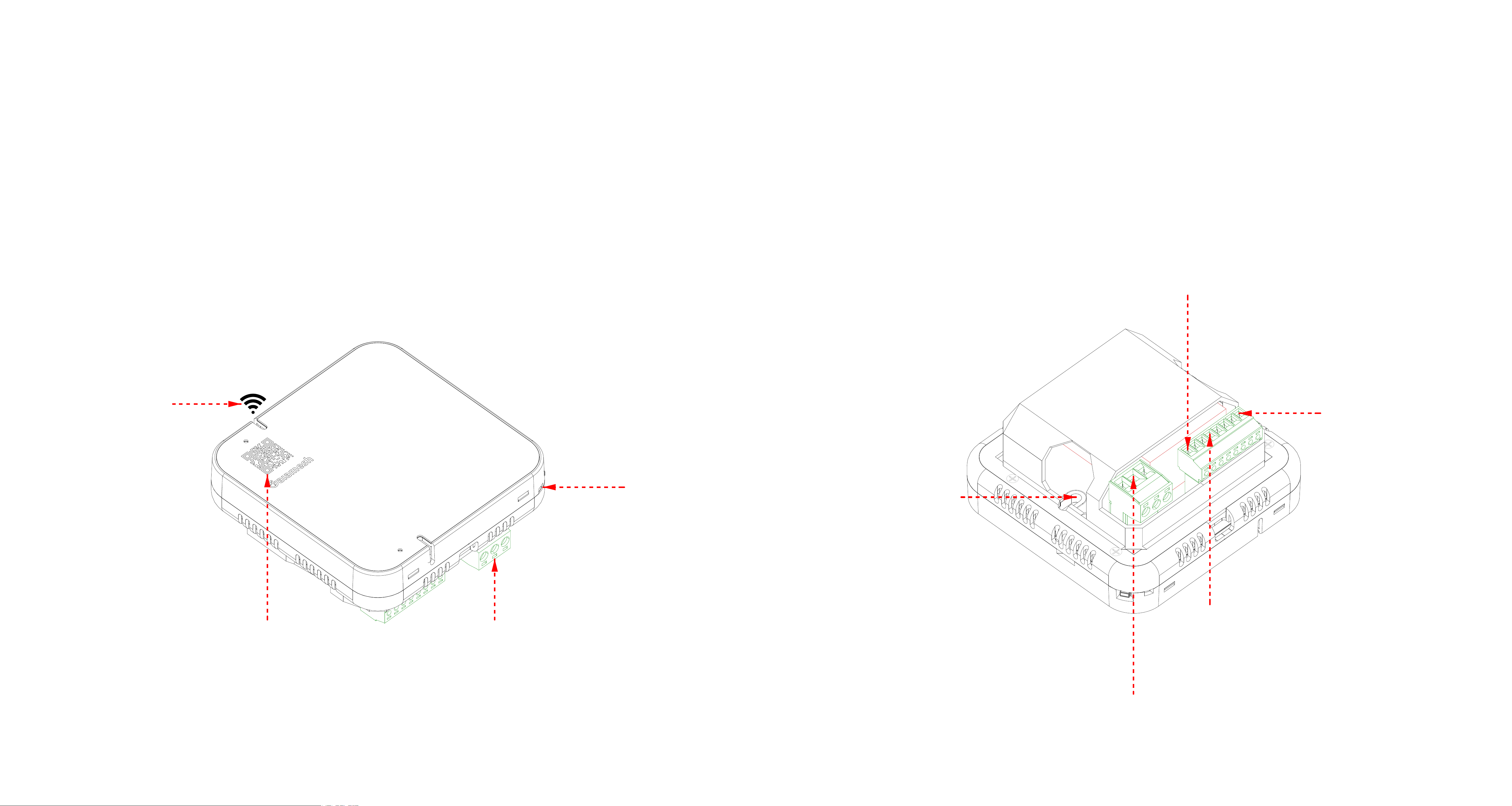
Scan QR code
to access
mobile interface
3.5mm 8P
pluggable
connector
Netconfig button
G
G
5V+
1W
B
Function
A
24V+
G
Front
Bottom
Digital sensor
Temperature
802.11 b/g/n
Top
L
Mesh Integrator (MI)
Wifi
24V DC output
Wireless connectivity Protocol
5V DC output
Wired IO
G
Power external devices
Sensor type
Power external devices
N
Integrates modbus devices
Included
integrates external temp sensors
Humidity
Modbus over RS485
Sensors
Option
1-WIRE
Green LED
(RS485 Tx)
Blue LED
(RS485 Rx)
White LED
(Connectivity)
Orange LED
(Power)
Left
Reset button
5mm 3P
pluggable
connector
Digital sensor
220V AC to 5V
DC power
converter
FCC Warnning:
This equipment has been tested and found to comply with the limits for a Class B digital device,
pursuant to part 15 of the FCC Rules. These limits are designed to provide reasonable
protection againstharmful interference in a residential installation. This equipment generates,
uses and can radiateradio frequency energy and, if not installed and used in accordance with
the instructions, maycause harmful interference to radio communications. However, there
is no guarantee thatinterference will not occur in a particular installation. If this
equipment does cause harmfulinterference to radio or television reception, which can be
determined by turning the equipmentoff and on, the user is encouraged to try to correct the
interference by one or more of thefollowing measures:
• Reorient or relocate the receiving antenna.
• Increase the separation between the equipment and receiver.
• Connect the equipment into an outlet on a circuit different from that to which the receiver is
connected.
• Consult the dealer or an experienced radio/TV technician for help.
Caution: Any changes or modifications to this device not explicitly approved by manufacturer
could void your authority to operate this equipment.
This device complies with part 15 of the FCC Rules. Operation is subject to the following two
conditions:
(1)This device may not cause harmful interference, and (2) this device must accept any
interference received, including interference that may cause undesired operation.
This equipment complies with FCC radiation exposure limits set forth for an uncontrolled
environment. This equipment should be installed and operated with minimum distance 20cm
between the radiator and your body.
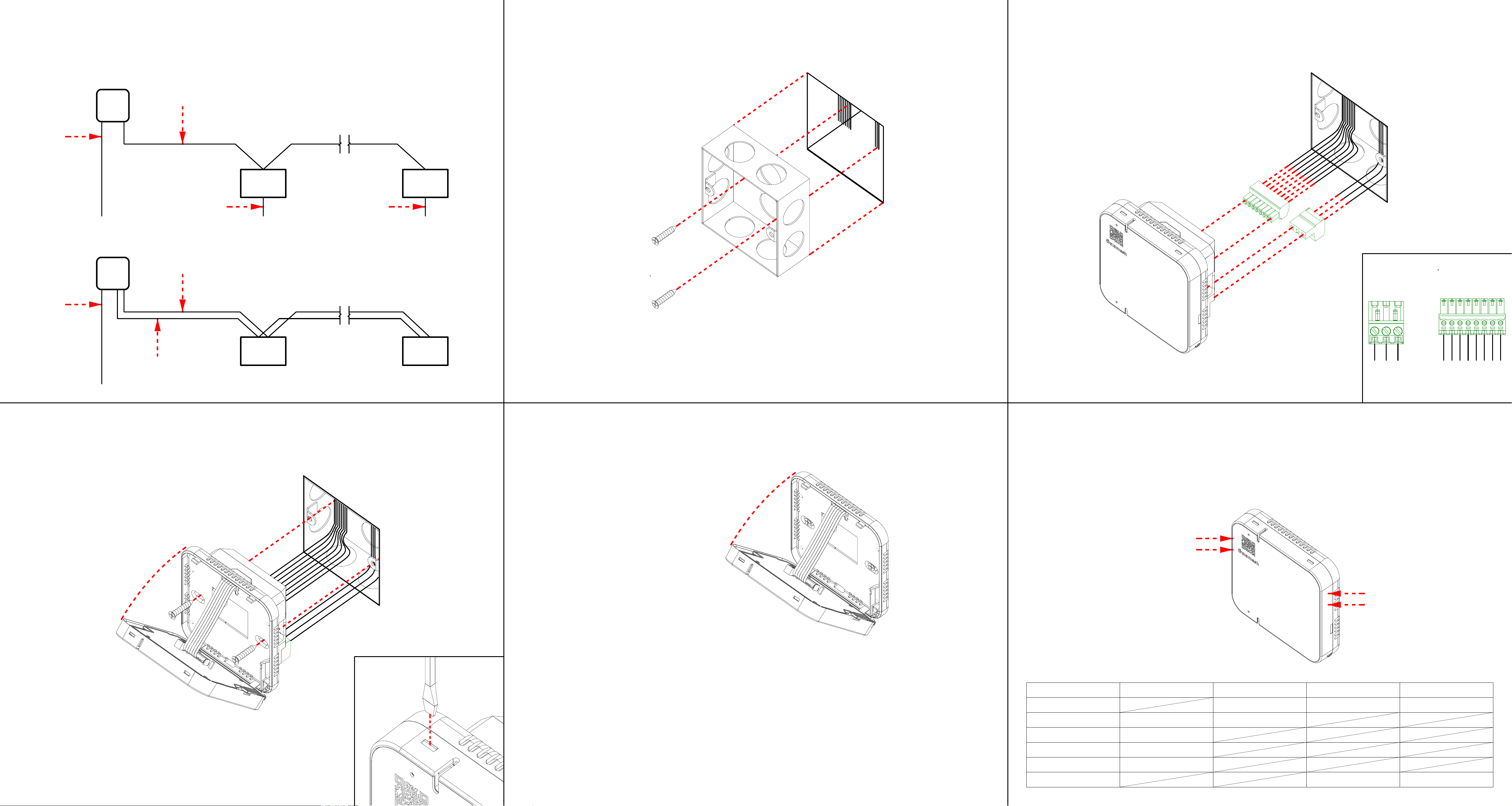
No Tx signal
See Modbus troubleshooting checklist
Step 1 - connect Modbus devices using RS485 cable (see Scenario 1) and
RS485 cable + DC power output cable (see Scenario 2)
No Rx signal
See Modbus troubleshooting checklist
Random blinking
Step 3 - connect power input wires to 3P connector, power output wires
(Scenario 2 only) and RS485 wires to 8P connector (see Detail A) and plug
connectors into node
Root node no connection
Contact tech support
Scenario 2: Devices powered from node
No light
G
N
L
24V+
Parent / Leaf node no connection
Contact tech support
No power - check power supply
...
...
A
Rx signal OK
G
Tx signal OK
Table 1 - LED Status
Power OK
Step 5 - close node lid
Blue LED (wireless connectivity)
Step 6 - power on and check LED status and ensure all LEDs are indicating an
"OK" status (see Table 1). Contact tech support if needed.
G
Detail A
Parent / Leaf node connectivity OK
Root node connectivity OK
Step 4 - use flathead screwdriver to open node lid (see Detail B), mount node to
86 box using 2 flathead screws
Node
5V+
Node
RS485
Green LED
Device 1
Orange LED (RS485 transmitting)
G
Orange LED
Device n
220V
White LED
220V
5VDC / 24VDC
RS485
1W
Continuously blinking
Device power source
Blue LED
Device power source
3 blinks + 3 sec pause
Device 1
Detail B
Device n
Green LED (power)
White LED (RS485 receiving)
B
2 blinks + 3 sec pause
Scenario 1: Devices powered externally
Step 2 - install 86 box inside wall (hidden installation condition, shown) or
mounted on wall (exposed installation condition, not shown)
Continuously on