Model No. DHD2400iSCO
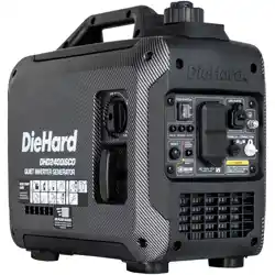
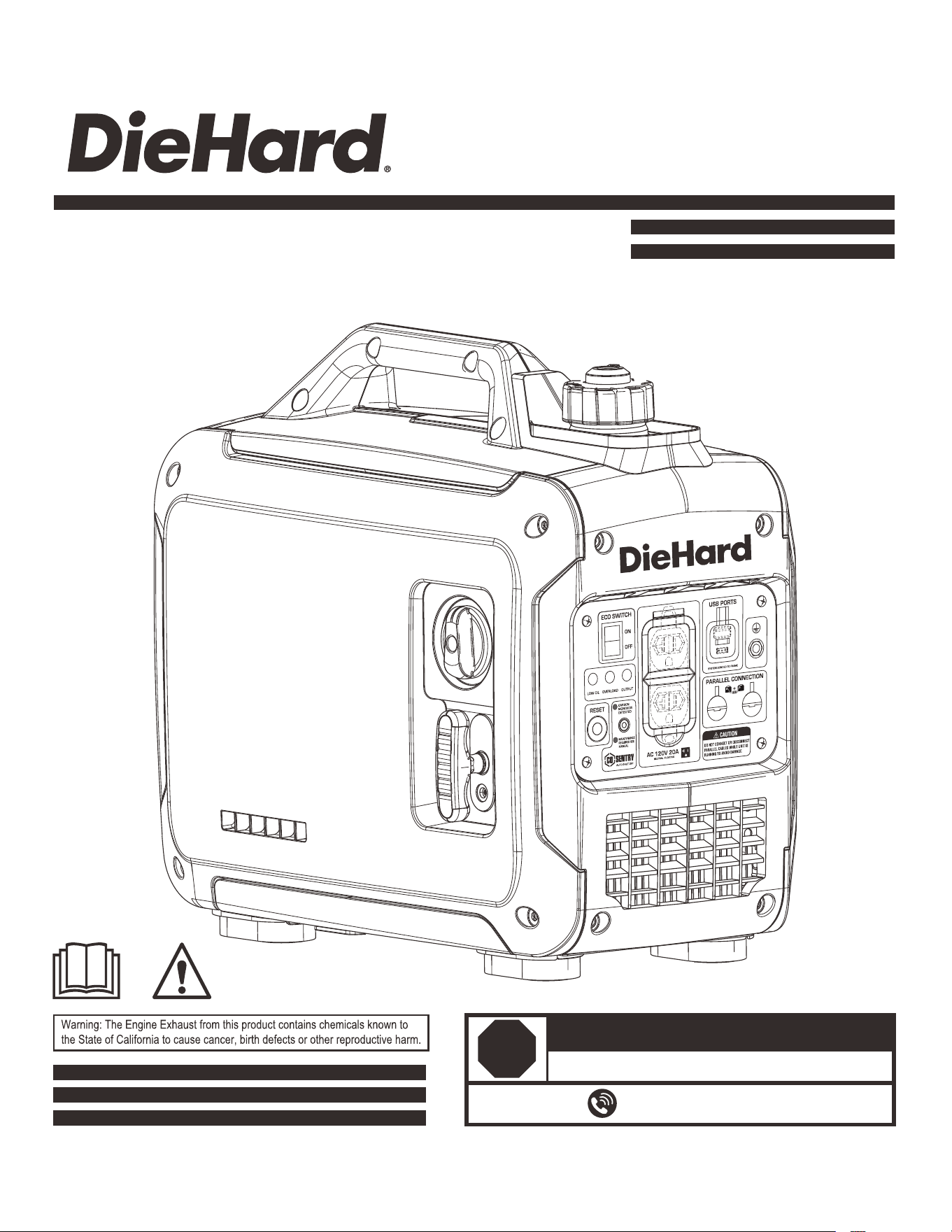
2400 WATT INVERTER GENERATOR
OPERATOR’S MANUAL
DO NOT RETURN TO STORE!
866-591-8921
HAVE QUESTIONS OR NEED SERVICE?
STOP
1
4
5
6
7
8
8
9
10
12
13
14
15
Introduction
Table of Contents
Safety Warnings and Notices
Thank you for choosing DieHard!
This manual provides instruction on how to operate and use your
generator safely and correctly; be sure to read and understand this
manual before using your generator.
If you have ANY questions, please call 866.591.8921 M-F
BEFORE using your generator. All details and images in this manual
are believed to be accurate at the time of publication.
If the generator is resold, kindly include this manual with the
generator.
2
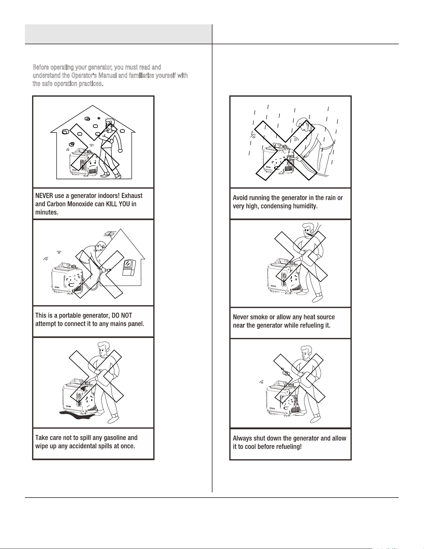
Before operating your generator, you must read and
u
nderstand the Operator's Manual and familiarize yourself with
t
he safe operation practices.
Safety Instructions
3
Safety Instructions
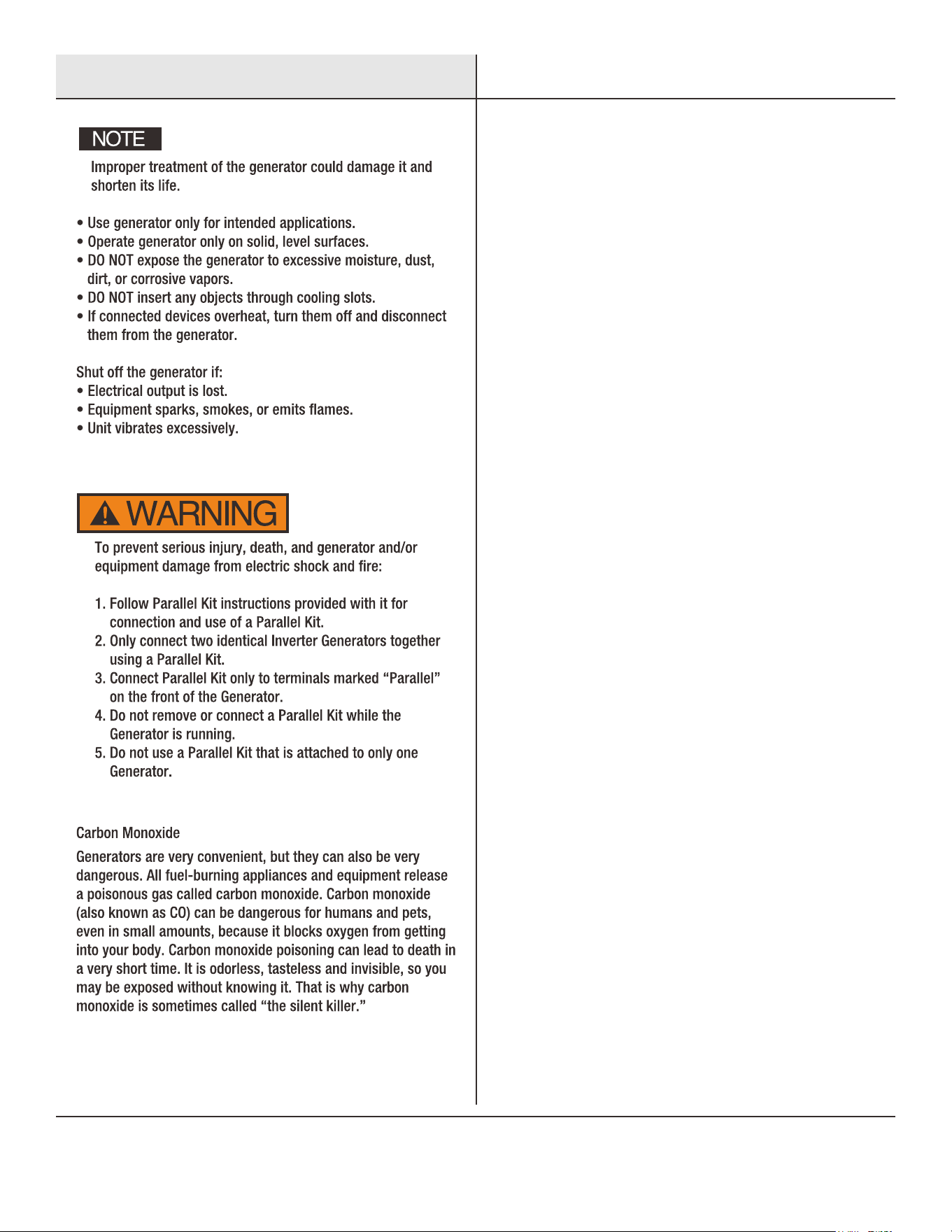
Parallel Kit Precautions
Carbon Monoxide Safety
4
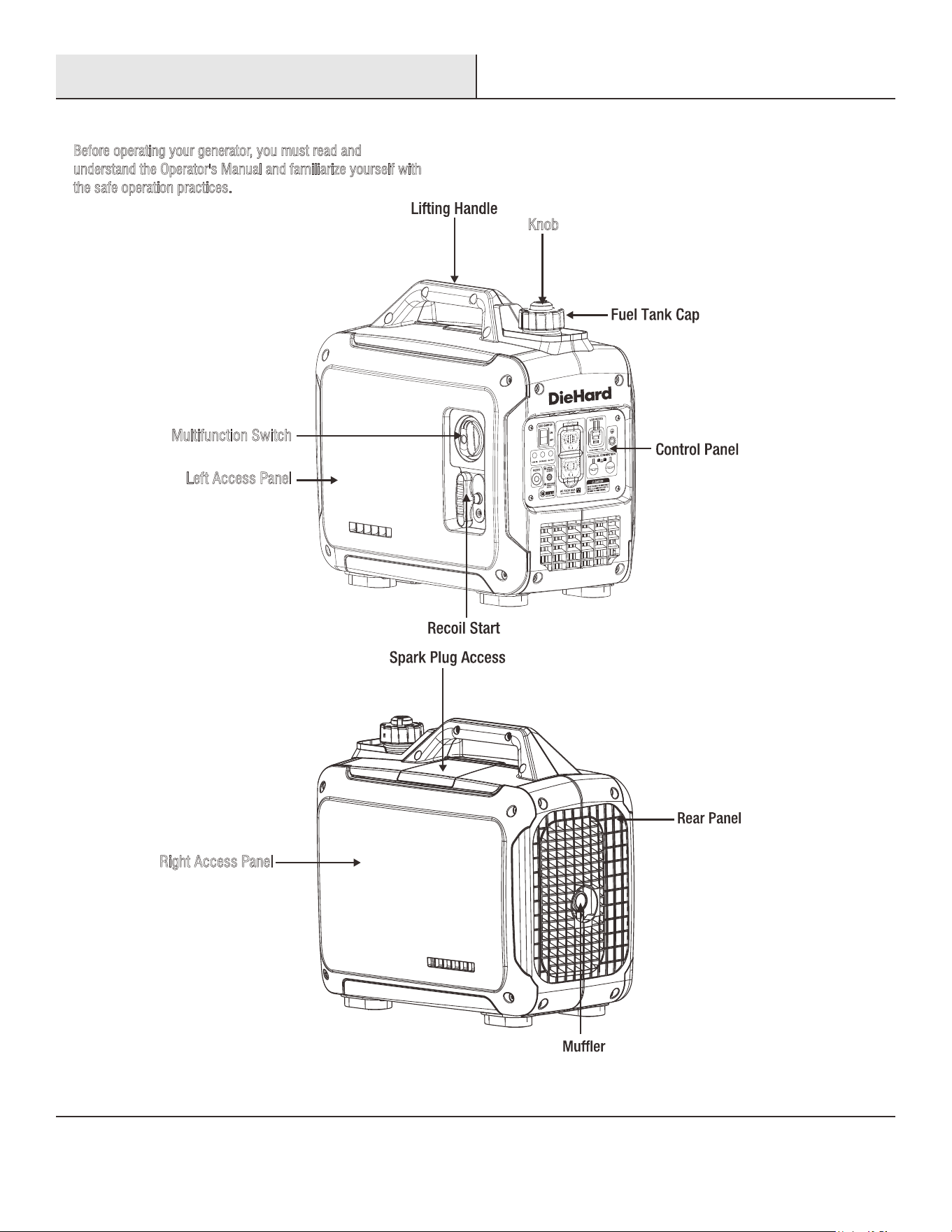
Knob
Multifunction Switch
Left Access Panel
Right Access Panel
Before operating your generator, you must read and
u
nderstand the Operator's Manual and familiarize yourself with
t
he safe operation practices.
Names of Components
5
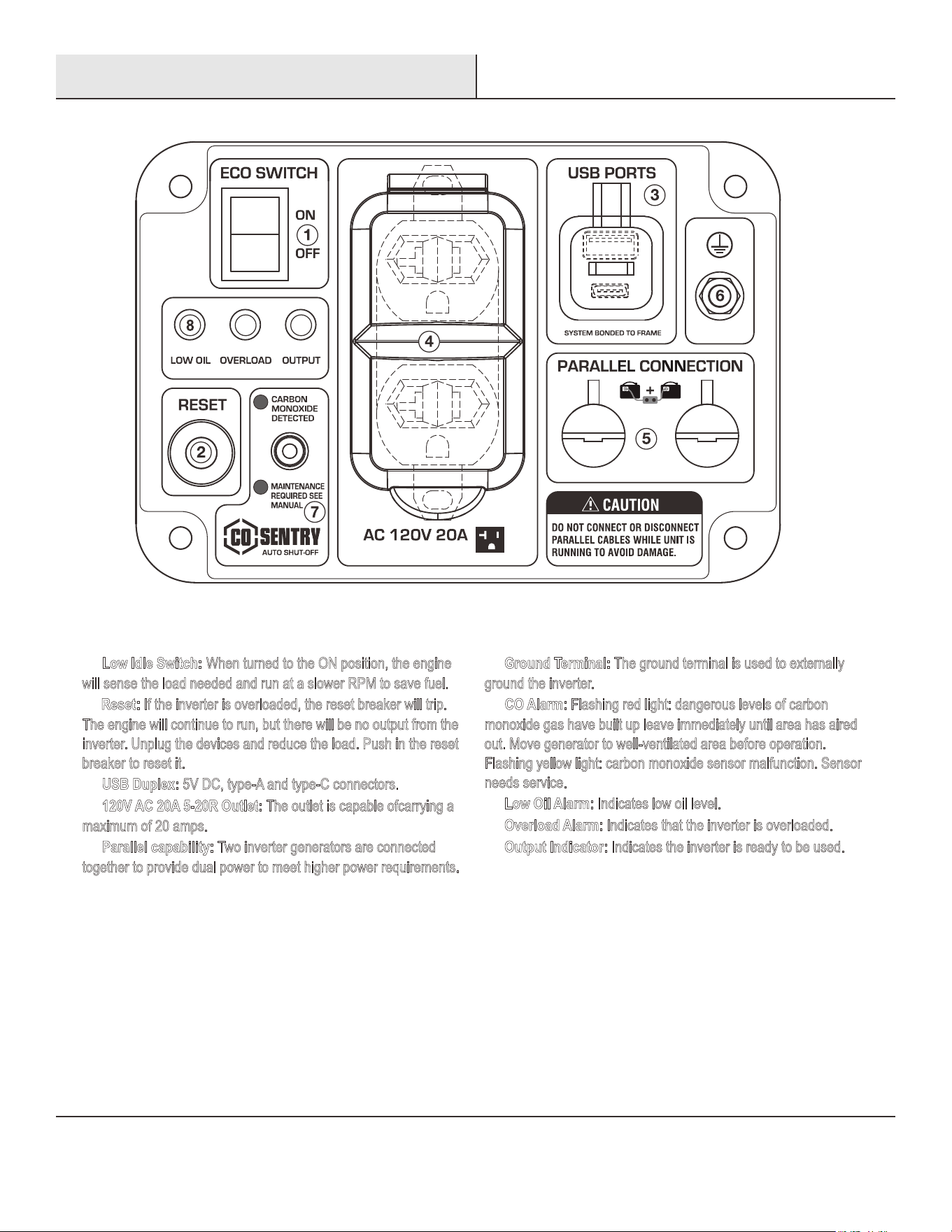
① Low Idle Switch: When turned to the ON position, the engine
w
ill sense the load needed and run at a slower RPM to save fuel.
② Reset: If the inverter is overloaded, the reset breaker will trip.
T
he engine will continue to run, but there will be no output from the
i
nverter. Unplug the devices and reduce the load. Push in the reset
b
reaker to reset it.
③ USB Duplex: 5V DC, type-A and type-C connectors.
④ 120V AC 20A 5-20R Outlet: carrying a The outlet is capable of
maximum of 20 amps.
⑤ Parallel capability: Two inverter generators are connected
t
ogether to provide dual power to meet higher power requirements.
⑥ Ground Terminal: The ground terminal is used to externally
g
round the inverter.
⑦ CO Alarm: Flashing red light: dangerous levels of carbon
m
onoxide gas have built up leave immediately until area has aired
o
ut. Move generator to well-ventilated area before operation.
F
lashing yellow light: carbon monoxide sensor malfunction. Sensor
n
eeds service.
⑧ Low Oil Alarm: Indicates low oil level.
⑨ Overload Alarm: Indicates that the inverter is overloaded.
⑩ Output Indicator: Indicates the inverter is ready to be used.
9 10
NEUTRAL FLOATING
Control Panel
CONTROL PANEL FEATURES
6
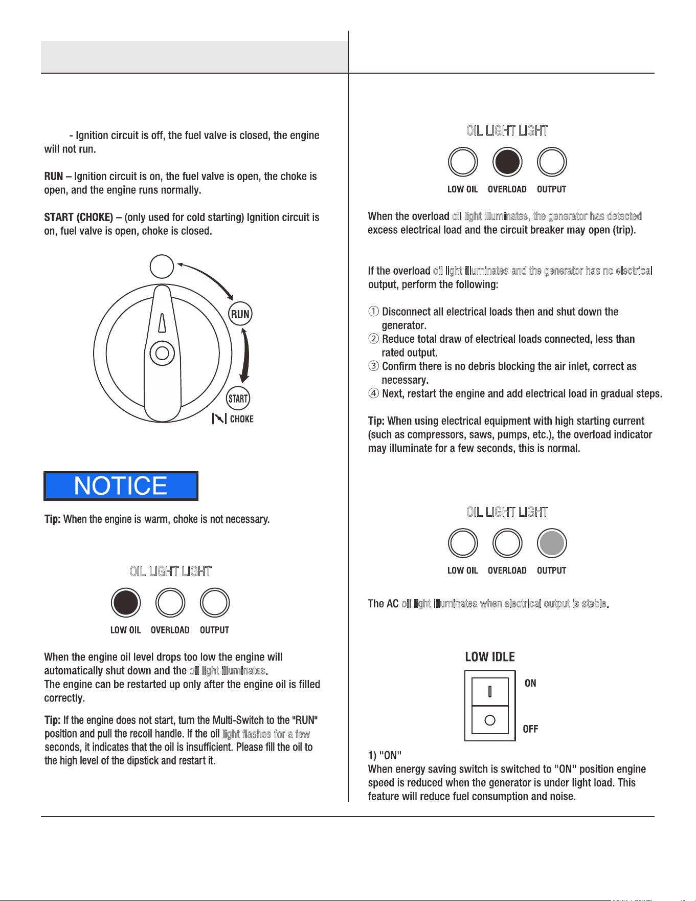
Multi-Switch
STOP
STOP
oil light illuminates.
light flashes for a few
oil light illuminates, the generator has detected
oil light illuminates and the generator has no electrical
OIL LIGHT LIGHT
OIL LIGHT LIGHT
oil light illuminates when electrical output is stable.
OIL LIGHT LIGHT
Control Functions
Multi-Switch
Oil Indicator (Yellow)
Overload Oil Light (Red)
AC Oil Light (Green)
Energy Saving (Idle) Switch
7
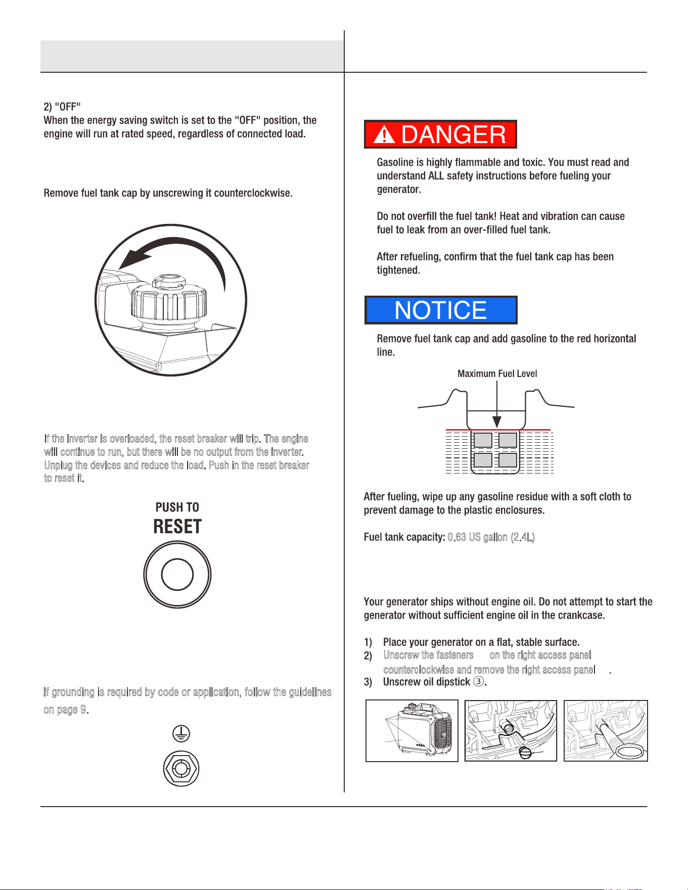
0.63 US gallon (2.4L)
If grounding is required by code or application, follow the guidelines
o
n page 9.
If the inverter is overloaded, the reset breaker will trip. The engine
w
ill continue to run, but there will be no output from the inverter.
U
nplug the devices and reduce the load. Push in the reset breaker
to reset it.
③
②
①
Unscrew the fasteners ① on the right access panel
c
ounterclockwise and remove the right access panel .②
Control Functions Preparing Your Generator
Fuel Tank Cap
Reset
Grounding Terminal
Fuel
Engine Oil
8
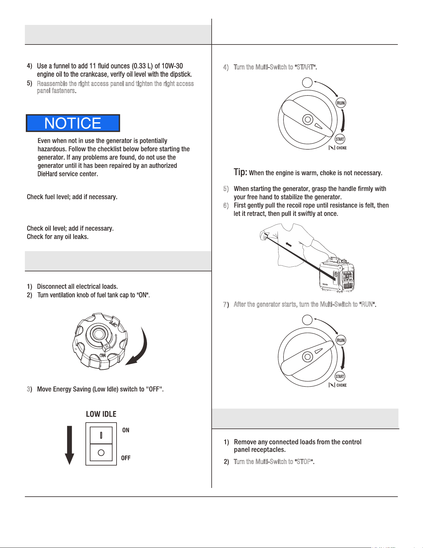
5)
6)
7
3
4)
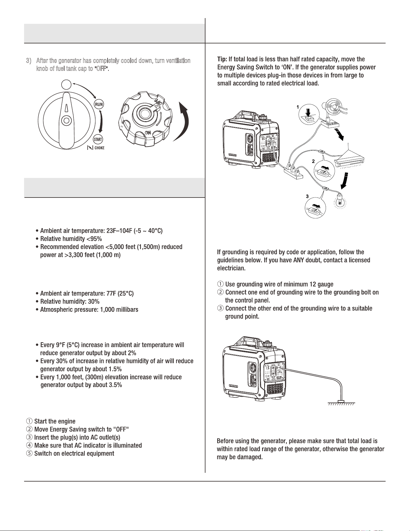
Turn the Multi-Switch to "STOP".
Turn the Multi-Switch to "START".
Multi-Switch
STOP
After the generator starts, turn the Multi-Switch to "RUN".
Multi-Switch
STOP
Reassemble the right access panel and tighten the right access
p
anel fasteners.
Preparing Your Generator
Starting The Generator
Shutting Down The Generator
Fuel
Oil
Pre-use Inspections
9
After the generator has completely cooled down, turn ventilation
k
nob of fuel tank cap to "OFF".
3)
Multi-Switch
STOP
Shutting Down The Generator
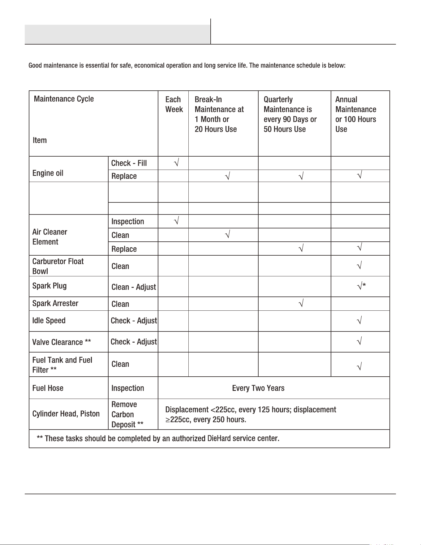
Using The Generator
Operating Range of the Generator
Ideal Atmospheric Conditions
Standard Deration
Connecting Loads to the Generator
Range of Application
Generator Grounding
10
Service and Maintenance
11
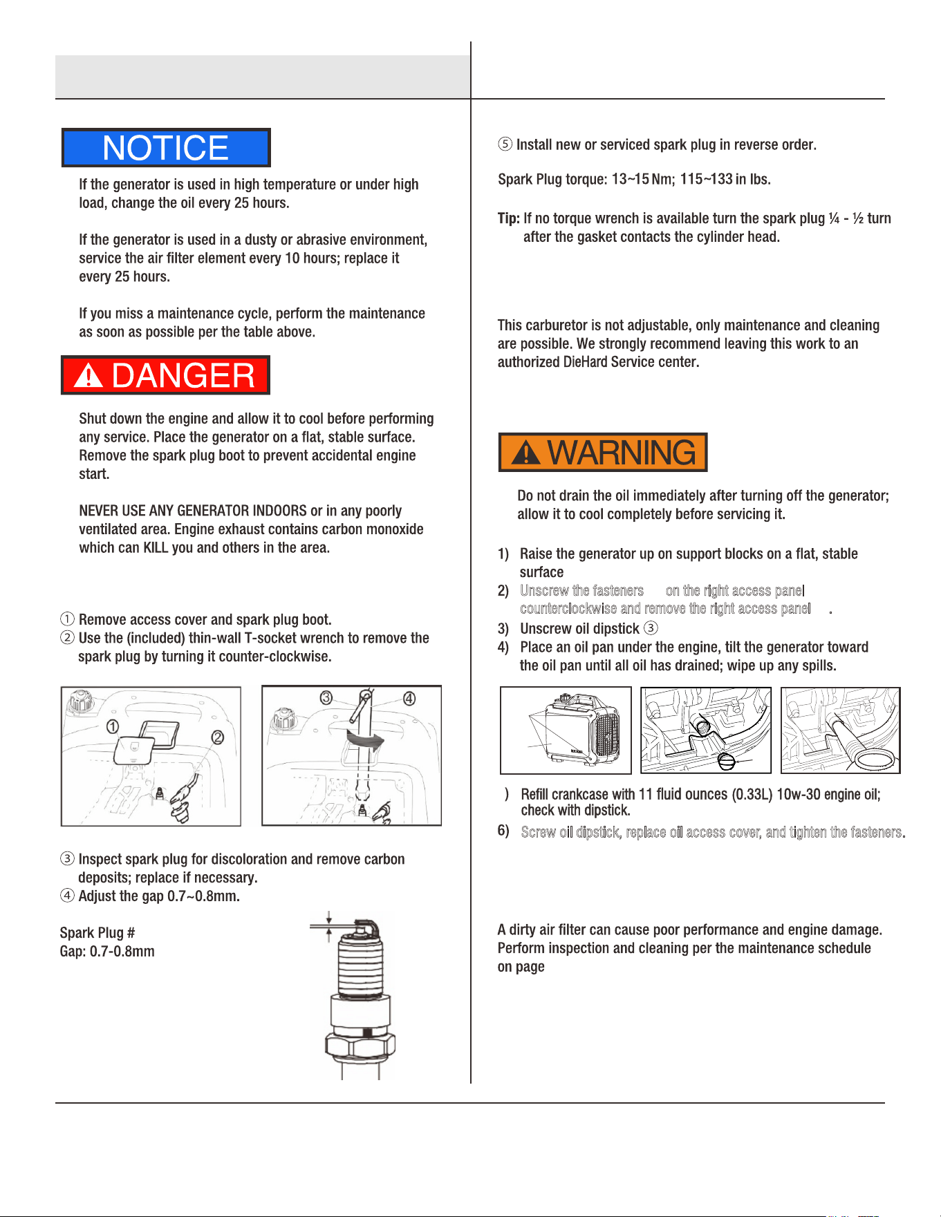
③
Unscrew the fasteners on the right access panel ①
c
ounterclockwise and remove the right access panel .②
②
①
10.
A5RTC
Screw oil dipstick, replace oil access cover, and tighten the fasteners.
5
Service and Maintenance
Spark Plug
Oil Change
Air Filter
Adjustment of the Carburetor
12
②
2
3
4
5
6
1). Turn off the generator and allow it to cool completely.
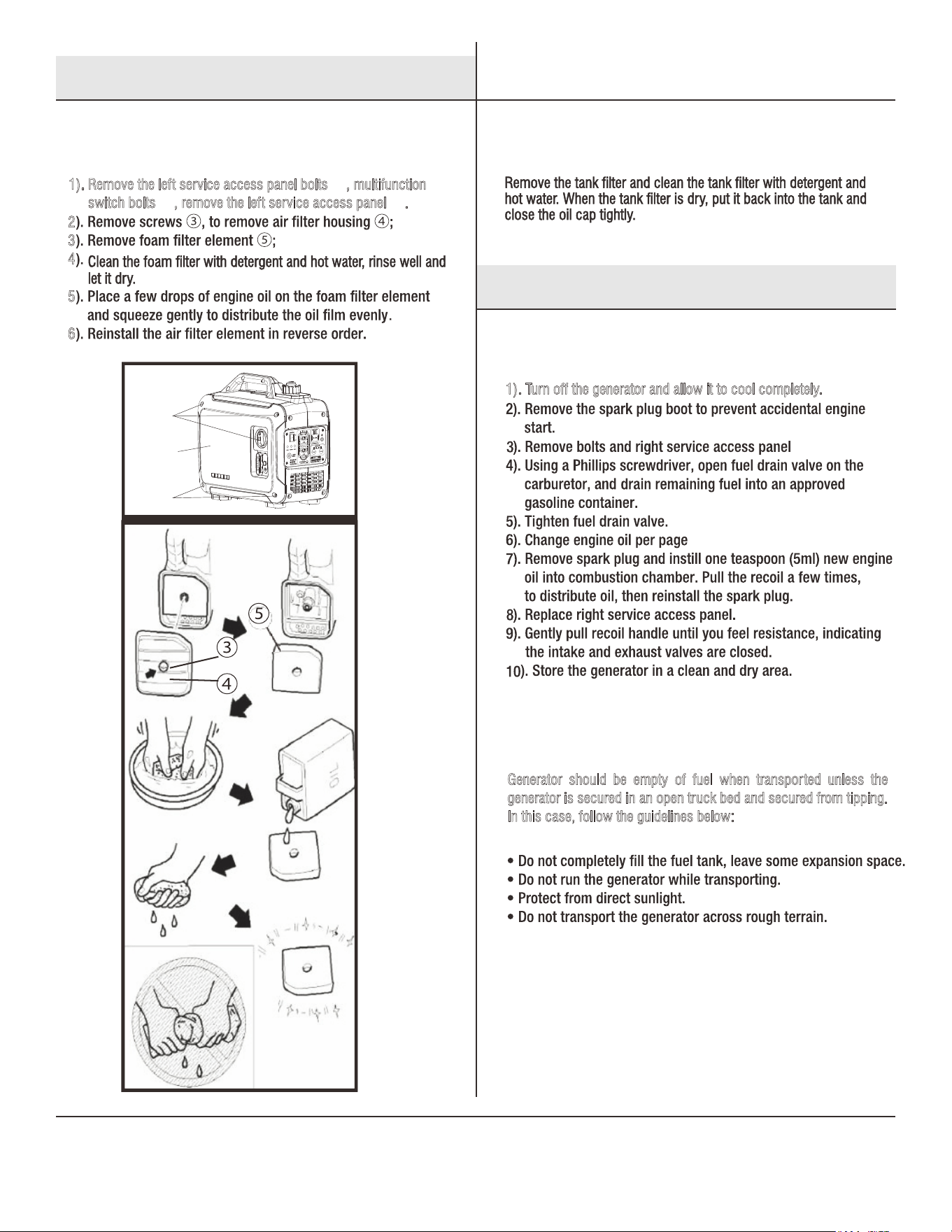
1). Remove the left service access panel bolts , multifunction ①
s
witch bolts , remove the left service access panel .① ②
①
①
10.
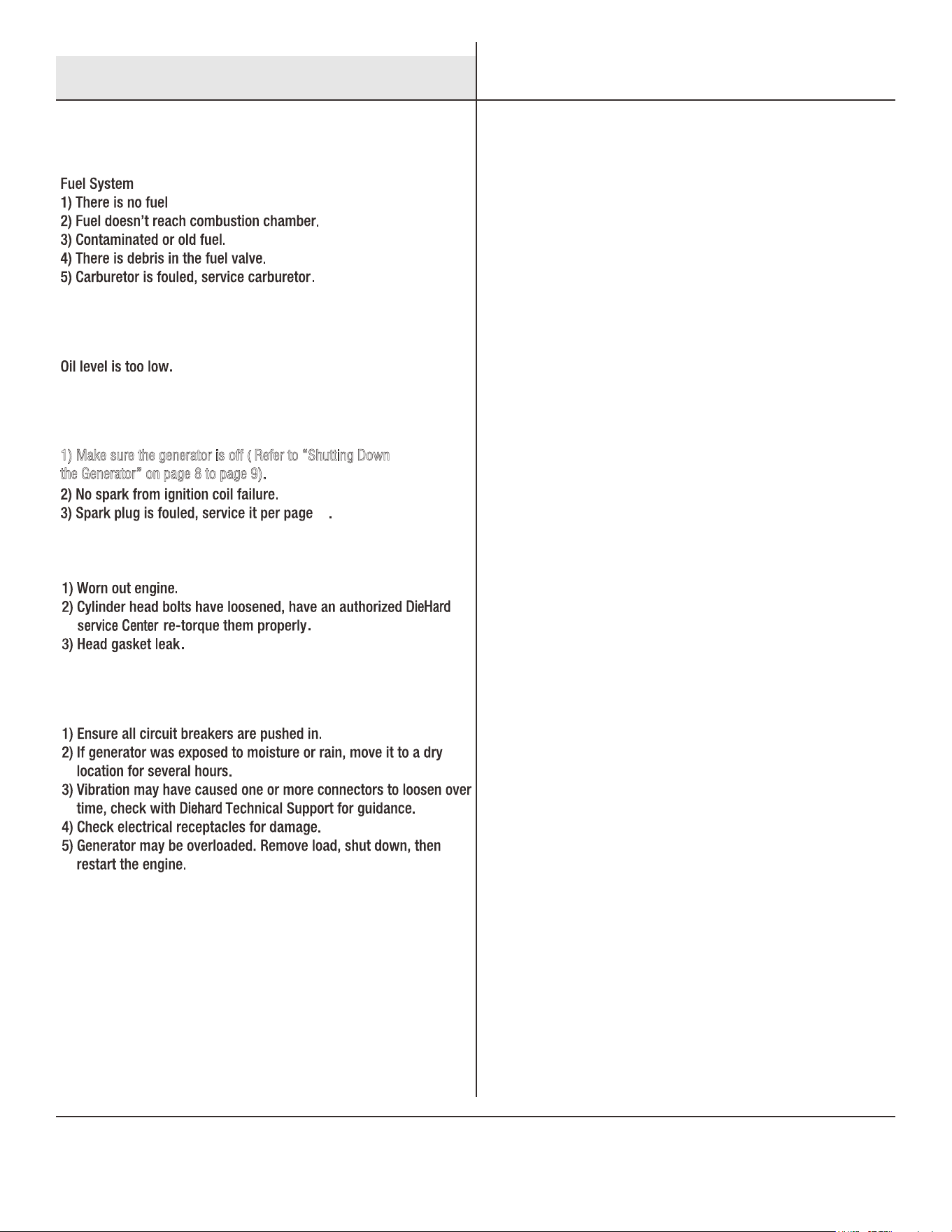
Generator should be empty of fuel when transported unless the
g
enerator is secured in an open truck bed and secured from tipping.
I
n this case, follow the guidelines below:
Service and Maintenance
Storage and Transport
Air Filter
Fuel Filter Screen
Generator Long Term Storage
Generator Transport
13
1) Make sure the generator is off ( Refer to “Shutting Down
t
he Generator” on page 8 to page 9).
11
Troubleshooting
Engine No-Start
Insufficient Engine Oil
Ignition System
Low Compression
Engine Runs, No Power Output
14
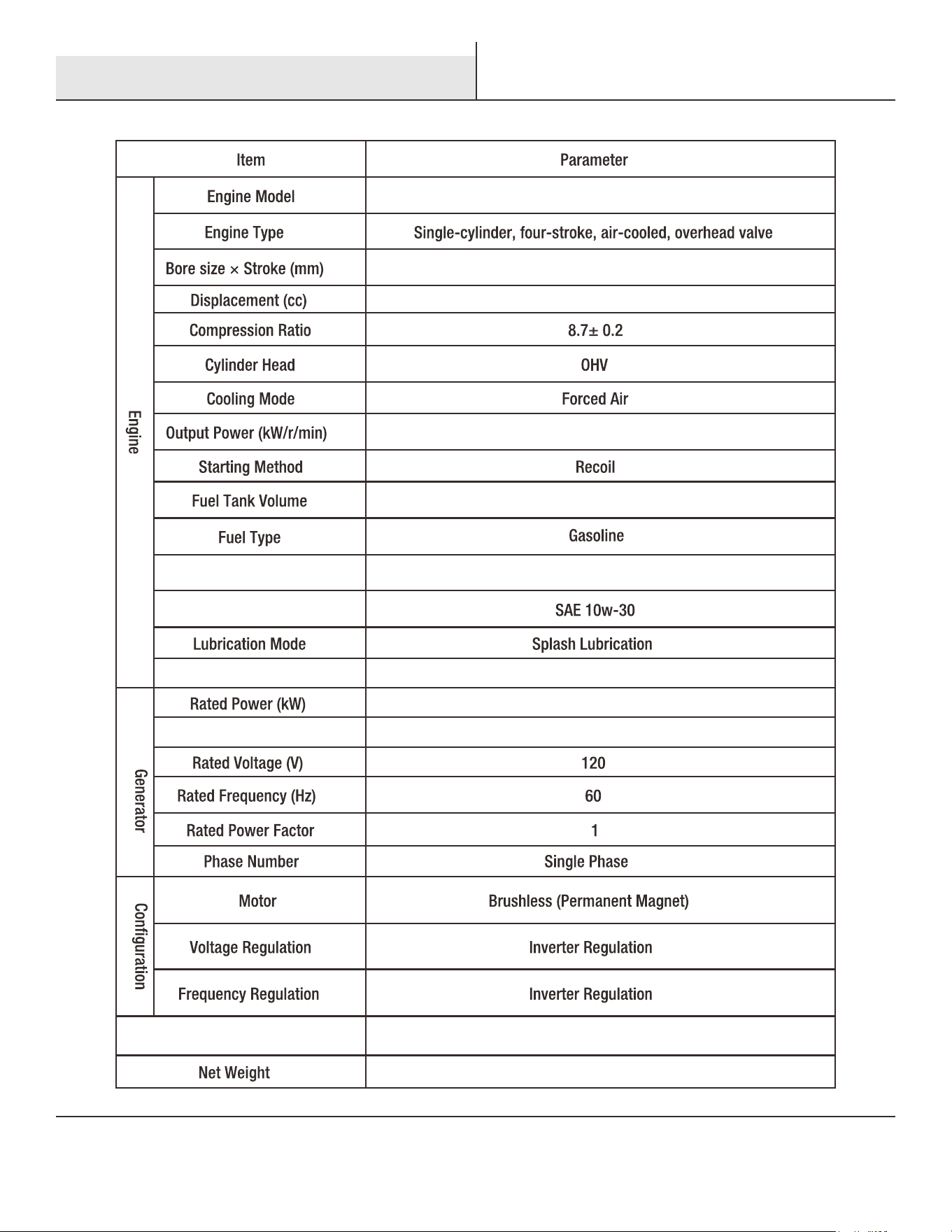
148F/P-3
48.6×43
79.7
0.63 Gallon (2.4L)
11 fluid Ounces (0.33L)
2.0
17.3”x9.8”x15.9”
33lbs.(15kg)
57
Noise dB (@ 7m)(1/4 load)
2.2/5000
Overall Dimension (in)
2.4Max. Power (kW)
Engine Oil Capacity
Oil Type
Technical Parameters
15
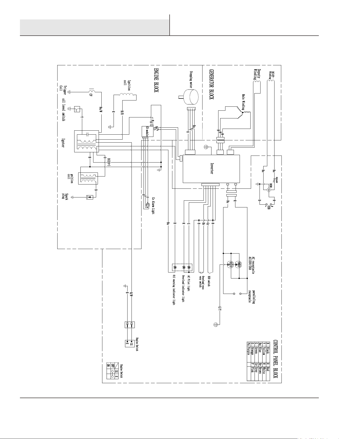
Electrical Schematic
60Hz, 120V Electrical Schematic Diagram

16



