
Dashcam
User Manual
(Version 1.1)

Revision record:
Actor
Version
Description
Date
Kevin
V1.0
First draft
2025/6/4
Kevin
V1.1
Replace new diagram
2025/8/28

Content
Actor ................................................................................................................................................................2
Version .............................................................................................................................................................2
Description ...................................................................................................................................................... 2
Date ................................................................................................................................................................. 2
1. Features
............................................................................................................................................................ 1
2.Dimension and Definition
.................................................................................................................................1
3.Quick Starts
........................................................................................................................................................2
3.1 Dashcam Configuration
........................................................................................................................3
3.2 Parameters set up via Howen-iTool
................................................................................................... 4
3.3 Time zone setting ......................................................................................................................................5
3.4 Quick connect to Platform
....................................................................................................................6
3.4.1 Device ID
..................................................................................................................................... 7
3.4.2 Center setting
............................................................................................................................. 7
3.4.3 Dial setting
...................................................................................................................................8
3.4.4 Add device to Howen VSS
....................................................................................................... 9
3.4.5 Network Status
........................................................................................................................... 9
3.5 Info page ................................................................................................................................................. 10
3.5.1 System
....................................................................................................................................... 11
3.5.2 Disk
.............................................................................................................................................12
3.5.3 AI Authorization
.........................................................................................................................13
4. Installation
....................................................................................................................................................... 13
5.Calibration
........................................................................................................................................................ 17
5.1 DMS Calibration ...................................................................................................................................... 17
5.2 ADAS Calibration ..................................................................................................................................... 19
6.Main Menu
....................................................................................................................................................... 23
6.1 Search ......................................................................................................................................................23
6.2 Config ...................................................................................................................................................... 24
6.2.1 Device
........................................................................................................................................ 24
6.2.2 User
............................................................................................................................................ 24
6.2.3 Clock
.......................................................................................................................................... 25
6.2.4 Power
......................................................................................................................................... 26
6.2.5 Sleep Configuration
................................................................................................................. 27
6.2.6 Disk
.............................................................................................................................................29
6.2.7 Audio
.......................................................................................................................................... 30
6.2.8 Parameter
..................................................................................................................................30
6.3 Video ....................................................................................................................................................... 31
6.3.1 General
...................................................................................................................................... 32
6.3.2 Main-stream
.............................................................................................................................. 32
6.3.3 Sub-stream
................................................................................................................................33
6.3.4 Timed Recording
...................................................................................................................... 34
6.3.4 Storage
...................................................................................................................................... 35
6.3.6 OSD
............................................................................................................................................36
6.3.7 Video Block
............................................................................................................................... 37

6.4 Network ...................................................................................................................................................37
6.4.1 Center setting
........................................................................................................................... 38
6.4.3 Dial setting
.................................................................................................................................39
6.4.4 Wi-Fi setting
.............................................................................................................................. 40
6.5 Alarm .......................................................................................................................................................41
6.5.1 I/O(Panic button)
...................................................................................................................... 41
6.5.2 External alarm
...........................................................................................................................43
6.5.3 Speed
.........................................................................................................................................44
6.5.4 G-sensor
....................................................................................................................................46
6.5.5 Voltage
....................................................................................................................................... 47
6.5.6 DMS
............................................................................................................................................48
6.5.7 ADAS
..........................................................................................................................................51
6.5.8 Face Setting
..............................................................................................................................52
6.5.9 Equipment Alarm
......................................................................................................................53
6.5.10 Overtime Driving
.................................................................................................................... 54
6.5.11 Other
.........................................................................................................................................55
Appendix-1 SMS command
...........................................................................................................................58
Appendix-2 Power consumption
...................................................................................................................59

— 1 —
1. Features
✓ Stylish new appearance
✓ Support AI features (optional): DMS, ADAS
✓ Compact design, least blocking for driver view sight
✓ Easy installation
✓ Detachable 2
nd
camera 720P/1080P, flexible for extension
✓ Cost-effective and more affordable
✓ Remote and local wake-up
✓ Support RS232
2.Dimension and Definition
LED color:
White: During the first minute device is powered on;
Green: Device connecting to platform;
Blue: Recording;
Purple: GPS working;
Red: Alert.
As the corresponding functions are activated, the LED light will change the corresponding colors in
sequence.

— 2 —
3.Quick Starts
Install Memory card and SIM card
The TF card (or Micro SD card) will be formatted automatically when it is inserted into the device for
the first time, the maximum is 512GB.
1.Recommended storage capacity 64GB-256GB, MLC material [Important!], Class 10 or above TF
card.
2. Require to use industrial grade SIM card (MP2 type), DO NOT use MP1 type SIM card.
Unscrew the cover at the bottom of device. Insert the SIM card and TF card, please mind the
direction.
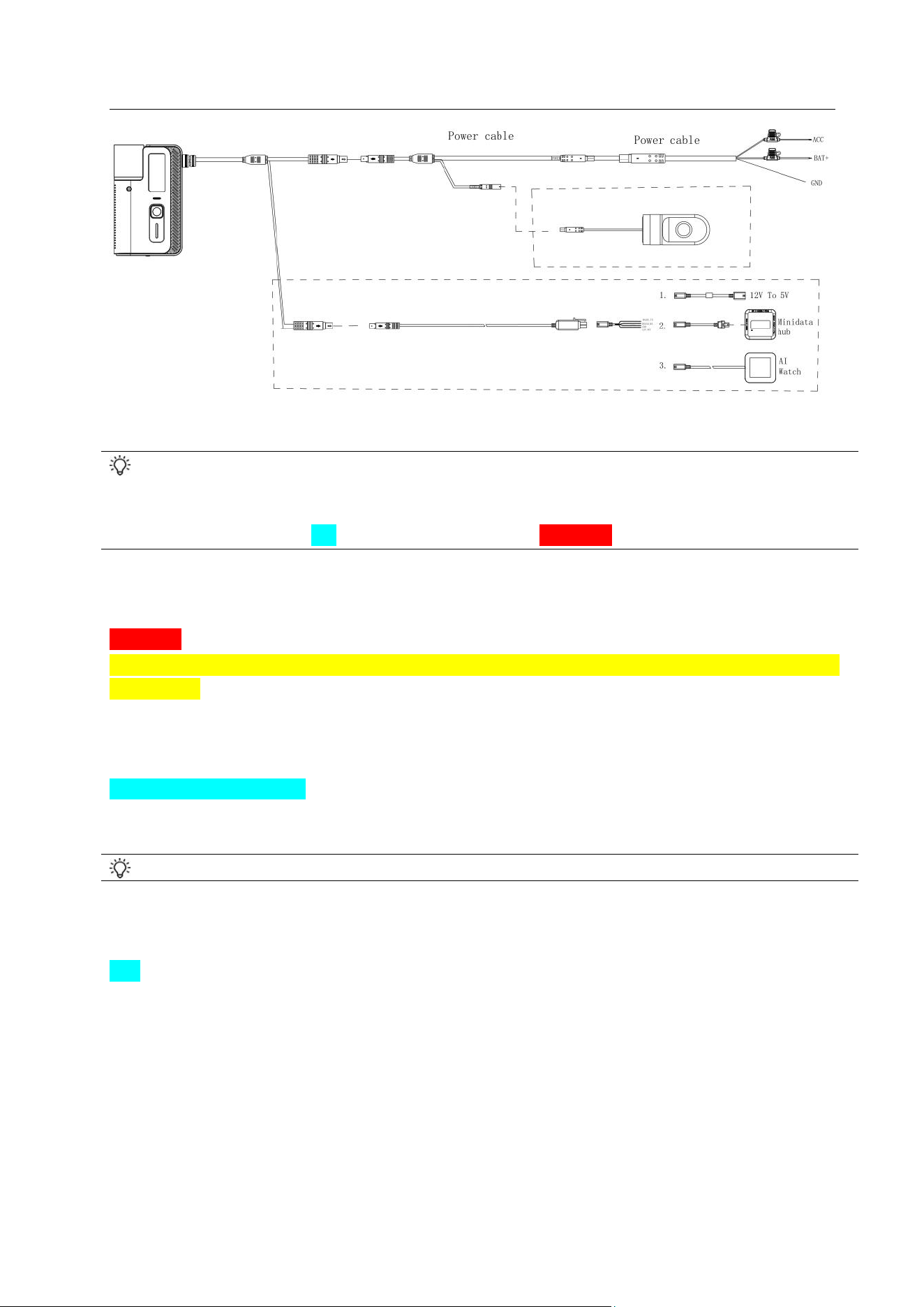
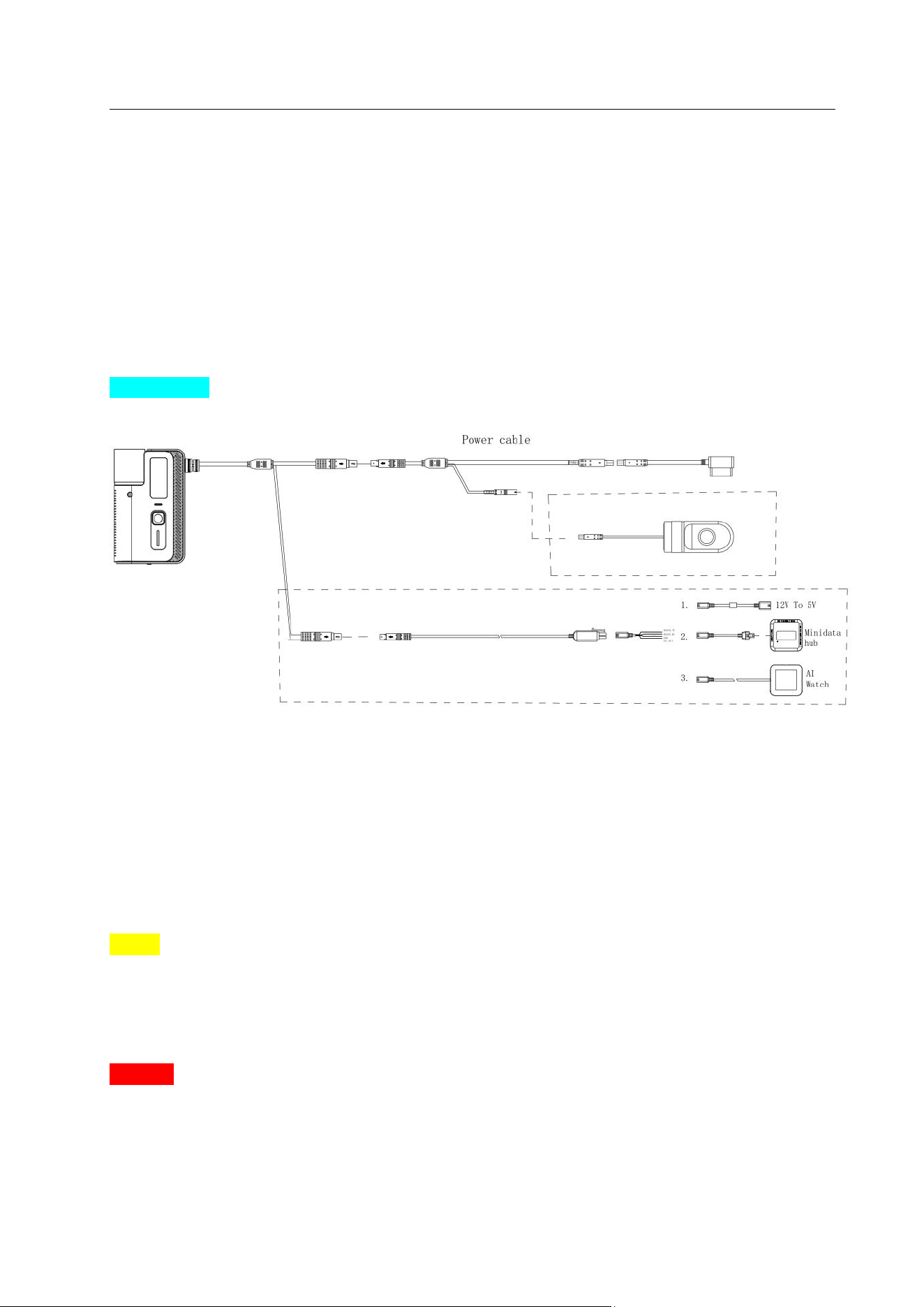
For Office test: DC12V, 5A power source is recommended. First connect the cable port to the
device side! Then connect red & orange wire to 12V’s positive and the black wire to GND.
Connection diagram:
— 3 —
3.1 Dashcam Configuration
Download “Howen-iTool” app from your mobile device (both Android and iOS versions
available).
The Wi-Fi name is APxxxxxx and the password is 12345678
Step1: Power on the Dashcam;
Step2: Search Wi-Fi shared by the Dashcam;
Step3: Connect your mobile device to this Wi-Fi, input the password.
Attention:
Use your mobile phone or tablet to connect Dashcam Wi-Fi within 2 minutes after the Dashcam is
powered on. Device will be in AP mode for 2 minutes then switch to Station mode. During these 2
minutes, if it connected via Howen-iTool, it will remain in connection mode. If the AP is
disconnected, please restart device to reconnect.
Search Dashcam via APP
Step1: Connect Wi-Fi shared by the Dashcam via your mobile device.
Step2: Open the Howen-iTool app, the APP will automatically search the device.
If auto search not started, please follow step 3.
Step3: Click the refresh button on the upper right of the page, it will start searching.
Tips: You can also use laptop to access this Dashcam Wi-Fi and configure via web in office.

— 4 —
The system IP address is 10.20.20.254
3.2 Parameters set up via Howen-iTool
Step 1: Input the password and log-in. Default login password is 111111;
Step 2: Click the Config button at the bottom, enter the configuration homepage
Step 3: Then you could start setting up parameters.
Fig.3.1 Login

— 5 —
Fig.3.2 Home Page
3.3 Timezone setting
Fig.3.3 Time

— 6 —
Fig.3.4 DST (Daylight Saving Time)
Timezone: Please set according to your preferred time zone, default setting is GMT + 08.
DST mode: Daylight Saving Time, set according to your local regulation.
Set the Month, Week, Days, specific hour, then set the offset time (normally 60 minutes, variable by
your local regulation).
For example:
This one means DST start from the first Sunday of April at 00:00, end at 00:00 of the last Sunday of
October, 1 hour forward.
3.4 Quick connect to Platform
Here are the steps to add device to platform quickly.
1. Create a unique device ID for the Dashcam. (3.4.1)
2. Input IP address and port in server 2, select H-protocol. (3.4.2)
3. Set the 4G(APN) Make sure dial successfully. (3.4.3 )
4. Add the device to Howen VSS or other 3
rd
party platform. (3.4.4)
5. Check the “Network” page, make sure it shows Connected. (3.4.5)
This is explained in detail below, please check.

— 7 —
3.4.1 Device ID
Step1: Go to Settings.
Step2: Click System>>Device Configuration.
Step3: Set it a unique device ID for it, it will be used to add Dashcam to the platform.
In addition, it is recommended to set the Plate NO. matching that of the vehicle in which the
Dashcam will be installed.
Fig.3.4.1 Device ID
Tips: New firmware which supports use IMEI as device ID, device will reboot after you set.
3.4.2 Center setting
The device will access Howen VSS platform or 3
rd
party platform via 4G/Wi-Fi.
Step 1: Settings >> Network.
Step 2: Click Center Settings.
Step 3: Select server 2, H-protocol.
Step 4: Select the H-protocol, input the server IP address and port.
Server IP: It’s your server PC’s public IP address which already deployed the platform.
Port: Default is 33000.
Server 1&2 both could support either Howen VSS or 3rd party platform at the same time, such as Wialon,
Navixy, Key, etc.
But do not set Server 1 and Server 2 to the same settings!

— 8 —
Fig.3.4.2 Center setting
3.4.3 Dial setting
Fig.3.4.3 Dial setting
Enable: On / Off.
Type: Device will automatically detect the SIM card type, and generally there is no need to change.
APN: Set for access point name for SIM card.
Notice: Each SIM card has a different APN , please ask your SIM card supplier.
Center No. : Default setting is *99#. Can not delete and generally don’t change it.
User name, Password: SIM card user name and password.
Recover: Auto reboot the 4G module when dial failed. Some SIM cards will not be recognized if
you turn on this menu, pay attention before you set this!

— 9 —
Telco: Currently only set for Verizon dial-up. Others don’t input it!
Scan: You can Scan the QR code to config device quickly.
QR code: You can share this QR code for other devices.
3.4.4 Add device to Howen VSS
Login to the Howen VSS platform via Web or VSS client.
Device No. Input device ID.
Device Name: Input Plate number.
Device Type: Select the device model.
Fleet: Need to create a fleet first. Then select this fleet.
Audio-video Number: Channel numbers, set according to the video channel needed.
Input/Output: Input according to device type.
Click to show more info about device, then save it.
Fig.3.4.4 Add Dashcam to VSS
3.4.5 Network Status
Go to system info menu, check the network info.
If it shows “dial failed”, please double-check the 3.4.3 Dial setting.

— 10 —
Fig.3.4.5 Network Status
Tips: New iTool could directly get the status from the icon.
: Green color means device is recording;
: Green color means GPS valid;
: Green color means 4G dial success;
: Green color means Server connected. Gray means Not link.
3.5 Info page
In addition to the network status info, there is other important information.

— 11 —
3.5.1 System
Check Status page, where you get general information about the device, e.g. MCU and firmware
version, device ID and plate number, GPS info etc.
Fig.3.5.1-1 INFO Page
Following information is important:
MCU version: MCU software version.
App Version: The current device firmware version.
Voltage: The current device operational voltage.
Device ID: Device ID.
LTE module & IMEI: 4G module information.
I/O status: Check I/O electrical level status.1 is high, 0 (lower than 3V) is low. You can check when
the panic button.
G-sensor: It shows the G-sensor value. Move the device and check if the values change.

— 12 —
Location Status:
It will show the longitude and latitude, satellites number. You can check more details for Satellites.
The signal intensity should be larger than 30dB, satellite number more than 4.
Fig.3.5.1-2 Satellites signal
3.5.2 Disk
Shows storage info.
Fig.3.5.2 Disk Info

— 13 —
Fig.3.5.3 AI Authorization
3.5.3 AI Authorization
ChipId: The Chip-set ID is for activating the DMS/ADAS function.
DMS/ADAS Authorization status: Activation status.
AI version: Algorithm version.
4. Installation
1. Take MC30-01 out of the package box. Insert SIM card and TF card, cover it with SIM card cover,
fix it with a short-screw.
2. Connect the 3-wires power cable or OBD power cable to vehicle battery.
— 14 —
OBD method
If you have purchased OBD cable, please connect the interface directly to Dashcam’s port.
For the 16-PIN OBD port, connect to your vehicle’s OBD interface.
3. Clean the pasting area on the windshield, find the best position to paste the bracket.
Notice: Before attaching the bracket, measure and mark the center of your vehicle's windshield.
A. Ensure that the surfaces where the tape will be applied is clean, dry, and free of grease. You
can wipe the surface with alcohol or a special detergent and wait for it to dry completely before
applying the tape.
Attention:
If the temperature is below 20 degrees, it’s recommended to use a hot-air cylinder to dry at 50
degrees for 5-10 seconds before pasting.

— 15 —
B. Apply Pressure: When applying the tape, make sure to apply enough pressure to ensure the
sticker is in full contact with the surface.
4. Slide the socket on the back of the Dashcam into the windshield mount until it locks.
Attention: DO NOT use the Long-screw, it will damage the device!!!
5. Turn the ignition ON, and open Howen-iTool to access the device,
If ADAS function is activated, need go to ADAS calibration view, make a roughly adjustment firstly.
Regarding how to calibrate ADAS accurately, please follow and refer to Part 5.2.
After calibrating/adjusting the cameras, tighten up the screw to fix the device.

— 16 —
6. If DMS function is activated, install them according to the camera type.
A. Standard camera[D3]
Install the DMS camera 60-120cm away in front of the driver, and 5-30 degrees that face to driver’s
eyes, make sure nothing laid between lens and driver. Angle is adjustable (left/right, up/down) to
make sure DMS camera could capture driver’s face entirely.
Attention: Currently not support fixing DMS cam on A-pillar of the vehicle.
Standard DMS camera position as shown below:
If the steer wheel blocked the view of DMS camera, try the following 2 options (also refer to the pics
below):
1. Install a holder to lift the DMS camera higher.
2. Move the DMS camera aside for 15-20cm or less than 15 degrees (towards vertical central line of
the driver face), but shall not across the vertical central line of the windshield. Then adjust the camera,
make sure it faces the driver, and driver face shall appear in the central field of camera view.
B. Wide-angle Camera

— 17 —
Tips: Please install the Wide-angle camera face to driver side a little, it’s better make the driver face
and camera view on same level as the right picture, it will affect the DMS accuracy a lot!
7. Please also check the basic information of device in INFO menu, such as dial status, TF card,
server connection status and satellites. Make sure all items work properly.
8. Hide the wire/cables, make it tidy.
5.Calibration
5.1 DMS Calibration
If your device supports DMS function, connect the DMS camera to the extension cable and select
CH2.
Attention: This model supports wide-angle camera(left-drive or right-drive) and Standard DMS
camera(external CH2).
1. Please go to Alarm>>DMS, and set the type first, then it will show different calibration method.
① Default: Standard camera which install on the dashboard
② Left drive: The driver in left side.
③ Right drive: The driver in right side.

— 18 —
Fig.5.1-1 Set Installation Position
2. After you install the camera, sit in front of the DMS camera, and face the camera lens.
Attention: The APP will show the valid area, must make sure your face in this area. If can not, please
adjust the camera location and angle.
3. Go to the AI Settings>>DMS , Click Submit
It will take a few seconds to enter calibration interface, please wait.
Fig.5.1-2 Standard DMS

— 19 —
Fig.5.1-3 Wide-angle DMS calibration
4. It will show “DMS Calibration successful” once done.
If failed, make sure you face to the center of the lens, adjust the camera angle and try calibration
again.
Fig.5.1-4 DMS calibration success
5.2 ADAS Calibration
1. Install the ADAS camera, and park the vehicle on a flat and open field.
Fig.5.2-1 Location
2. Go to ADAS setting menu, point the ADAS channel to CH1.
3. Calibrate Horizon&Car Center
A. Put a pole or ruler in the front of vehicle, the distance is 3~5m, and the pole or ruler should be in
same line with camera center in vertical direction.

— 20 —
B. Mark a line which is the same height with ADAS camera’s center[Need measure the camera
height as below] on ruler. Then modify these parameters correctly.( Fig.5.2-3)
Fig.5.2-2 Ruler or Pole Position
Fig.5.2-3 ADAS calibration step
For explanation:
Vehicle Width: The width between the outter edge of tires. Unit: cm. (Fig.5.2-4)
Camera Height: The distance from the ground to center of camera. Unit: cm. (Fig.5.2-6)
Camera to Bumper: The distance from camera to front bumper. Unit: cm. (Fig.5.2-6) For flat cabin,
input 0.
Camera to left wheel: The camera center to the left wheel distance. Unit: cm. (Fig.5.2-5)

— 21 —
Fig.5.2-4 Vehicle Width Fig.5.2-5 Camera to Left wheel
Fig.5.2-6 Camera Height and Bumper
C. Move the Horizon Red line up or down, make it overlap with the marked line on the ruler.
Move the Vehicle center-line Blue line overlap with the ruler in vertical direction.
Attention: The ruler/pole must align with ADAS center line.
For explanation:
Horizon Line: The horizontal level, which get from calibration, do not input manually. Unit:Pixel.
Vehicle center-line: The offset (distance) from the camera center, calibrate to get. Unit: Pixel.
(Fig.5.2-7)

— 22 —
Fig.5.2-7 Horizon&Car middle
Tips: How to make sure the calibration is well:
Check real-time preview by iTool. Refer to the picture above, the horizon should be aligned with the
ground 30 meters away and occupy 1/3 to 1/2 of the vertical position of the screen.
4. After calibrate the Horizon and Car middle , Click “Save”
Fig.5.2-8 ADAS Calibration
If it fails, Please double-check each step and redo it.

— 23 —
6.Main Menu
6.1 Search
Make sure there is a TF card in the Dash cam and the recording function is working properly. Switch
to homepage.
Fig.6.1 Search
Channel: Select the channel requested.
Type: Normal recording, alarm recording, Image, Log file and Black box file.
Start time: Select the start time for video search.
End time: End time for video search, default is the current time.
Once video is available, you can export it to external USB drive (which need connect via OTG tool) or
to your mobile device.
Fig.6.1 Playback

— 24 —
6.2 Config
The configuration menu contains Device, User, Clock, Power, Sleep mode, Disk, Audio, Serial
and parameter.
6.2.1 Device
Device ID
Set a number (up to16 digits), but it must be unique, which is very important.
Plate NO.: It will display on the OSD for live streaming. It’s better set it same as Plate number.
Position Mode: GPS, GPS+BD [Default] or GPS+GL.
Fig.6.2.1 Device
6.2.2 User
Fig.6.2.2 User

— 25 —
The default admin password is 111111
Password enable:On/Off
ON (Recommended): Administrator can set or change parameters, so if you need to set certain
parameters, log in with this account.
OFF: When there is no password, the menu will be entered directly.
6.2.3 Clock
Fig.6.2.3-1 Date &Time
Fig.6.2.3-2 DST
Date Type: For selecting the date type, year - month - day, day - month – year, month - day - year.
Time Sync: Time synchronize method: Off / GPS / NTP, default is GPS.

— 26 —
Time zone: Please set according to your time zone, default is GMT + 08.
DST mode: Daylight saving time is to set clocks forward by one hour in the spring ("spring
forward"), and to set clocks back by one hour in the fall ("fall back") to return to standard time. Need
set it according to your local country requirement.
Set the Month, Week, Days, specific hour, then set the offset time(normally it’s 60 minutes).
(Fig.6.2.3-2)
For example:
This one means DST start from the first Sunday of April at 00:00, end at 00:00 of the last Sunday of
October, 1 hour forward.
6.2.4 Power
①Auto Reboot: Automatically restart the device for maintenance. If set ON, the device will reboot
at the Reboot Time.
Tips: If the device run 24 hours each day, we recommend to set it ON, then set a Reboot time.
②Power off: You can set a voltage limit for prevent draining the battery, device will automatically
power off when voltage less than this limit.
Fig.6.2.4-1 Power
Power Mode: Ignition mode / timing mode.
Ignition mode: On/Off by the vehicle’s ignition status.

— 27 —
Timed mode: On/Off according to the user’s time setting.
Fig.6.2.4-2 Power
Timed mode
Power on: Setup power on time under timing mode.
Power off: Setup power off time under timing mode.
③Ignition mode
Shutdown delay: After the ignition switch is turned off, the Dashcam will continue to work and will
only shut down after the delayed shutdown time you set is reached.
14400 minutes means the device will keep working for 10 days. Please set reasonable parameters
for it.
Turn off video delay: When ignition is turned off, set the record delay time, it will continue to record
during this period. This time can’t exceed the Delay shutdown time .
Record Channel: Check the channels for delay recording.
6.2.5 Sleep Configuration
It supports device wake-up by Timed, remote(SMS or phone-call) or G-sensor mode. It will turn on
and run for a few minutes according to the settings, upload GPS and start recording.

— 28 —
Fig.6.2.5-1 Sleep mode
Remote Wake-up: You can wake up device via phone call or SMS(any message).
Attention: This depends on the telecom provider and not all providers support it.
Time Mode & Timed Interval: The device will wake up by the setting interval. (Fig.6.2.5-1)
G-sensor mode & G-sensor: The device will wake up by the impact/hit value of G-sensor.
(Fig.6.2.5-2)
Running Time: The working time after device wakes up. Unit is minute, the minimum is 1 minute.
Attention: The whole running time: this time plus the Power menu’s Shutdown delay time.
Upload GPS: 4G module switch, and upload GPS information. It will upload GPS location after
device power off if you enable it.
Power-on snapshot: Select the channels to take snapshots.
Power-on Record: Select the channels to record video.
Dormancy alarm: Device will upload this wake-up alarm to platform.
Wake-up Alarm
Enable this alarm, when the vehicle ignition is off and the device is in sleep mode, this alarm can be
triggered

— 29 —
Fig.6.2.5-2 Wake-up alarm
6.2.6 Disk
Encrypt Key: For safety concern, we can set a password (Key) for the dedicated channels.
When playing by Howen video player, user will be asked to input the password.
Encryption Channel: Select the channel to encrypt.
Once memory card is inserted, Disk Name will be shown, click to enter.
Fig.6.2.6 Disk format
It will show the whole capacity of storage, the unit is GB. To set it as standard, you can set via
Standard Partition.
For Dashcam, AI video/picture will be saved in the Standard part of TF card, so need to set a proper
space for it. Default is 3GB, not recommend to change.

— 30 —
6.2.7 Audio
Speaker Volume: 0-5 scale, 5 is Maximum.
Power-on Sound: The chime sound when startup.
TF card Import: Import customized voice package to device from the TF card.
Mobile phone Import: Import customized voice package to device from the Phone.
Fig.6.2.7 Audio
6.2.8 Parameter
1.Mileage: You could set an initial value or restore it to the original set-up. (Fig.6.2.8-1)
Restore default: Could restore most setting except some important items, such as device ID, 4G,
Server setting.
Restore All parameters: Could restore all settings to default settings.
2.Parameters Export: Export the current configuration to your smartphone.
3.Parameters import: Import configuration from smartphone to other devices.

— 31 —
Fig.6.2.8-1 Parameter
Fig.6.2.8-2 Parameter import/export
Tips:
After setting the parameters for a device, you can export them and then import the set parameters
into other devices. After the import is complete, the device will automatically restart once.
6.3 Video
Recording setup including:General, M-stream, S-stream, Time recording, Storage, OSD set.

— 32 —
6.3.1 General
Fig.6.3 General
TV System: PAL / NTSC, default is PAL. Device will automatically detect it.
Record Mode: Auto / time recording / alarm recording, default is Auto.
①Auto: It will record all the time.
②Time recording: Need set the time in [Timed Record].
③Alarm: Only do recording when an alarm is triggered,which should set in the Alarm menu first.
Camera Type: The device will automatically detect camera type.
Encoding format: Support H.264 and H.265.
6.3.2 Main-stream
Fig.6.3.2 Main stream

— 33 —
Main-stream is for recording video locally. (Fig.6.3.2)
Enable: On / Off. You could disable unused channel.
Resolution: Select: CIF/D1 / HD1/ 720P/1080P.
CIF:352*288, HD1:352*576, D1:704*576, 720P:1280*720, 1080P: 1920*1080.
Frame rate: Frames Per Second (FPS). NTSC: 30FPS, PAL: 25FPS.
Quality: Video quality, 1-8 steps optional. 1 refers to the best video quality. And1-5 will consume more
storage.
Audio: ON means the audio will be saved with video together, device has one built-in microphone.
Time-lapse Recording: It will only record 1 frame for storage efficiency. Maximum time-lapse
recording time interval is 2s, Minimum is 0.2s.
Mirror: Only CH2 supports Mirror feature.
6.3.3 Sub-stream
Fig.6.3.3 Sub-stream
The sub-stream is used for live streaming(default). The higher the Resolution&bit rate &frame rate,
the clearer the image will be, but more SIM card data will be consumed.
Notice: QUA, 1 refers to the best video quality. To save cellular data, suggest to set it as 5 or 6.

— 34 —
6.3.4 Timed Recording
Fig.6.3.4 Timed Recording
Set the start time and end time. During the setting time, it will automatically start recording.
Attention:
1.Need turn on the Time mode first, in the Video-˃General-˃Record mode-˃Timed mode;
2.Set the ALL as 00:00:00-00:00:00, otherwise timed recording will NOT work!
3.Set the recording plan for each day.

— 35 —
6.3.4 Storage
Fig.6.3.4 Storage
Alarm Previous Rec: Set the previous recording time before the alarm happens. 0 to 60 seconds for
selection.
Alarm delay: Set the delay recording time after the alarm happened. 0 to 3600 seconds for selection.
Alarm file to server: Alarm file upload to FTP or HFTP or NO.
Alarm file protection: Set the alarm file protection days, those files will NOT be deleted during the
set days. Set a proper value for it.
Attention: To upload files to FTP server:
1.Must set Alarm file protection days.
2.Set a reasonable space for Standard Partition in section 6.2.6 Disk.
Usage: No / Record
1.No: No recording;

— 36 —
2.Record: Recording the file in this disk.
Alarm file stream: Supports main-stream or sub-stream. You can choose sub-stream for saving SIM
card data.
6.3.6 OSD
Set the stamp information on the image, and location to be displayed on the image.
Fig.6.3.6-1 OSD
Date: Time display switch.
Ch: Chanel name and Plate number display switch.
GPS: GPS information display switch.
Driver ID: User information.

— 37 —
And now the Speed test is also displayed on the OSD(Fig.63.6-2)
Fig.6.3.6-2 OSD
6.3.7 Video Block
Fig.6.3.7 video block
Enabling Video block could place mosaic on a set area of camera view.
Region name: select the video block region name;
Color: select the video block color;
X&Y: input number keys to set the X and Y coordinates on the image;
Width & Height: set the width and height of the block.
6.4 Network
Network Setup page: Center settings, Dial settings and Wi-Fi settings.

— 38 —
6.4.1 Center setting
The device will access Howen VSS platform or 3
rd
party platform via 4G/Wi-Fi.
Step 1: Config >> Network.
Step 2: Click Center Settings.
Step 3: Select server 2, H-protocol.
Step 4: Select the H-protocol, input the server IP address and port.
Server IP: It’s your server PC’s public IP address which already deployed the platform.
Port: Default is 33000 for VSS.
Server 1&2 both could support either Howen VSS or 3rd party platform at the same time, such as Wialon,
Navixy, Key, etc.
But do not set Server 1 and Server 2 to the same settings!
Fig.6.4.1-1 Center setting
GPS Interval: Time interval for the device to report GPS information to the platform.
GPS Angle Filter: GPS Angle optimization, when the vehicle turns or U-turns, the GPS will track the
change of the vehicle's traveling Angle and upload to platform.
Degree: Turning Angle.
Last Valid GPS: When the GPS is invalid, the device uses the last valid GPS info to upload.
Report UTC+0: The device reports the UTC+0 time’s message(GPS/Alarm) to the platform.
More features
FTP server: You can build your own FTP server, and upload video/picture to it.
Timed snapshot: Take snapshots according to the set interval and upload snapshots to VSS.

— 39 —
Fig.6.4.1-2 FTP server & Timed snapshot
6.4.3 Dial setting
Enable: On / Off.
Type: Device will automatically detect the SIM card type, and generally there is no need to change.
APN: Set for access point name for SIM card.
Notice: Each SIM card has a different APN , please ask the SIM card supplier.
Center No. : Default setting is *99#. Can not delete and generally don’t change it.
User name, Password: SIM card user name and password.
Recover: Auto reboot the 4G module when dial failed. Some SIM cards will not be recognized if
you turn on this menu, pay attention before you set this!
Fig.6.4.3-1 Dial setting

— 40 —
6.4.4 Wi-Fi setting
In office test, you can also use Wi-Fi to access internet, device will use Wi-Fi as priority. To set up,
simply follow your WIFI router’s configuration.
Fig.6.4.4 Wi-Fi setting
After you set, please restart the device and wait a while, it will connect to your office Router.
Wi-Fi Enabled: Turn it On.
Encrypt Enable: On / Off.
Auth Mode: Open / Shared / WPA / WPA-PSK, set according to your router configuration.
EncType: NONE /WEP/ TKIP / AES, set according to your router configuration.
Work Mode: Station or AP.
DHCP: Turn it on/off, default is On. Change it only if you need to set a static IP address.
AP mode:
If switch to AP mode, you can share the 4G network to access internet.
AP work time: The hotspot duration.

— 41 —
6.5 Alarm
Alarm menu contains I/O, Speed, Geo-fence switch, G-sensor, voltage, DMS and ADAS.
Fig.6.5 Alarm menu
6.5.1 I/O(Panic button)
Enable: Off, Panic and reverse.
Level: High. High means it will trigger sensor alarm when the sensor voltage input is changed from 0
to a high voltage [DC 4V - 12V].
Delay: The alarm duration time after trigger source is removed, it is used for setting linkage’s duration
time. During this period, it will not response the new alarm if there is a continuous triggering.
Wait: In order to prevent the user from accidentally touching and triggering the alarm, the system
waits for a period of time.
Fig.6.5.1-1 I/O setting

— 42 —
Record: Recording as an alarm video.
Buzzer: Turn on/off voice notification.
RecLockChn: Copy the alarm files to REC-Alarm folder of TF card.
RecUploadChn: The files will be uploaded to Howen VSS (HFTP) or FTP server.
Attention: For NO-AI alarm video, the channel need match in RecLockChn and RecUploadChn,
they are a pair setting.
For example, if you need to upload CH1, need select CH1 in RecLockChn and RecUploadChn, or
else, it will not upload!
AlarmOutput: N/A.
SnapPicChn: Select the channel for snapshot. Snapshots will be saved in TF card, and upload to
FTP server.
Tips: If you don’t need to receive the repeat alerts when I/O been triggered, select Single mode.
Fig.
6.5.1-2 Panic button setting
Only when you set the type as Panic, they can define the functions of panic button.
Urgent report: Means a panic alert will be uploaded to platform.
WIFI AP: Reboot the AP for configuration.

— 43 —
6.5.2 External alarm
6.5.2.1 Geofence
This feature is designed for Geofence, if you have released Geofence to the device from VSS
platform, please enable it.
When Geofence triggers an alarm, it pushes the alarm content to the platform and reports the ID of
the fence
Fig.6.5.2.1 Geofence
6.5.2.2 SIM Alarm
The SIM card cannot detect alarms. If the device cannot detect the SIM card for a long time, the
device generates an alarm, which is cached locally and uploaded to the platform after the network
recovers.
Fig.6.5.2.2 SIM card alarm

— 44 —
Enable: Turn on or off this function.
Interval: The device cannot detect the SIM card duration threshold.
Record: Recording as an alarm video.
Buzzer: N/A
RecLockChn: Copy the alarm files to REC-Alarm folder of TF card.
RecUploadChn: The files will be uploaded to Howen VSS (HFTP) or FTP server.
Snapshot Chn: Upload the alarm picture to the platform.
6.5.3 Speed
It contains Parking (parking time setting), L-Warn (low-speed warning), L-ALM (low-speed alarm),
H-Warn (high-speed warning), H-ALM (high-speed alarm), Spd Up (speed up), Spd Down (speed
down), spd Idle (idle status).
Enable: On / Off.
Limit: Parking limit unit is second; Others limit is Speed you set.
Delay: Linkage’s duration time. During this period, it will not response the new same alert.
Wait: The waiting response for false triggering could be set to prevent false alarm.
Record: Turn on/off recording function.
Buzzer & Premode: N/A.
RecLockChn: Copy the alarm files to REC-Alarm folder of TF card.
RecUploadChn: The files will be uploaded to Howen VSS (HFTP) or FTP server.
Attention: For NO-AI alarm video, the channels need match in RecLockChn and RecUploadChn,
they are a pair setting.
For example, if you need to upload CH1, need select CH1 in RecLockChn and RecUploadChn, or
else, it will not upload!
AlarmOutput: N/A.
SnapPicChn: Select the channel for snapshot. Snapshots will be saved in TF card, and upload to
server.
Speed Source: GPS[default] / Vehicle / Mix.
Pulse: N/A.
Speed unit: KM/H, Mile/H or NM/H.
Attention:
1. Parking: Ignition off status, when it passed the Limit [Unit is second] you set, then it will upload
the first alarm, if still parking, the rest will be upload by the Delay time [Unit is second] you set. For
parking, no need to set Wait.
2. Idle: Vehicle ignition on, when vehicle speed is less than the speed Limit, after the Wait time you
set, it will upload the first alarm, the rest will be uploaded by the Delay time [Unit is second] you set.

— 45 —
3. Speed up/down: HA/HB, Harsh Acceleration/Harsh Braking. Use the speed compare to get
alarm.
For the "Speed HA" line, you can set the limit to 8, so if the driver drives 50km this second and 55km
the next second, there will be no HA alarm; if the driver drives 50km this second and 60km the next
second, the HA alarm will be triggered.
For the "Speed HB" line, you can set the limit to 8, so if the driver drives 50km this second and 45km
the next second, there will be no HB alarm; if the driver drives 50km this second and 40km the next
second, the HB alarm will be triggered.
Fig.6.5.3 Speed

— 46 —
6.5.4 G-sensor
The acceleration alarm contains X, Y, Z, impact, tilt, HC (Harsh Cornering), HA (G-sensor Harsh
Acceleration), HB (G-sensor Harsh Brake).
Enable:Select ON/OFF.
Limit: Tilt unit is angle, the others are g (m/s
2
).
Wait: To prevent system misjudgment or false alarm, the delayed response time can be set. Unit is
second, minimum is 0.1s.
Delay: Linkage’s duration time, Unit is second. During this period, it will not respond to new alarms
if there is continuous triggering.
Record: Turn on/off alarm recording function.
Calibration Method:
Manual Calibration: After the device is installed, you need to enter the G-sensor setting page
manually, click Calibration, and return the G-sensor value to zero.
Automatic Calibration: After the device is turned on, it will automatically calibrate the reference
value (the reference value of the device at static state);
Install: No setup required.
Adjust: After you install the device, press this button to restore x/y/z value to zero.
Fig.6.5.4-1 G-sensor

— 47 —
HA/HB/HC: which use G-sensor to detect the harsh acceleration, harsh braking and harsh corner.
Since G-sensor is quite accurate, so each type of vehicle need to adjust.
The unit is g, for small vehicle, set as 2~3 for your reference.
6.5.5 Voltage
When the operation voltage value is low, alarm will be triggered. Dashcam’s operational voltage is
8-36V (Lower the voltage, higher the current will be drawn), 12V/24V input is recommended.
Enable:On/Off.
Limit: Set a voltage threshold.
Delay: The alarm duration time after triggering source is deactivated, it is used for setting linkage’s
duration time.
Wait: To prevent system misjudgment or false alarm, the delayed response time can be set.
Record: N/A.
Fig.6.5.5 Voltage

— 48 —
6.5.6 DMS
DMS supports Smoking, Phone call, Eye closed, Yawning, Distracted driving, Absent (No driver),
Infrared sunglasses, seatbelt, Camera Coverage detection and Fatigue driving.
Camera Chn: CH2.
AI Draw: AI alarm video frame. When the AI alarm video is triggered by the device, the detected
driver behavior will be marked with the frame;
Attention: This function consumes system resources and is not recommended when AI alarms are
frequently triggered.
Install: Select an installation location. The device adjusts its detection area based on the installation
location. Default is for DMS install on the dashboard.
① Default: Standard camera which install on the dashboard
② Left drive: The driver in left side.
③ Right drive: The driver in right side.
Fig.6.5.6-1 Set Installation Position

— 49 —
Fig.6.5.6-2 Standard DMS
Fig.6.5.6-3 Wide-angle DMS calibration
Enable: Turn on/off this alert.
Speed: The alert triggering speed or threshold, unit is KM/H.
Pre-Recording: Recording time (Unit: Second) before alert, could set it as 3 to 5 seconds.
Duty ratio: The ratio of the number of frames used for algorithm analysis to the total number of
sampled frames.
DMS: 8 frames(total frame number) will be sent to NPU per second. If it is set to 70% and the trigger
hold time is 3 seconds, it means 3*8*70%=17 frames. When this value is reached, the alarm will be
triggered.
In addition, 70% is the recommended value. If it is set more. For example, 85%, the alarm will be
more accurate, but it may miss alarms; if it is set too low, such as 60%, it will be very sensitive and
receive some false alarms.

— 50 —
TriggerHold: Wait or Hold time.
Interval: The trigger interval (Unit: Second) for the following same alert.
Distracted: Distracted driving detects the driver's turning Angle threshold, up, down, left and right.
Fig.6.5.6-4 Fatigue driving
Fatigue Driving: The fatigue driving alarm is determined according to the number of closed eye
alarms triggered. When the number of eye-closing alarms triggered reaches the threshold within a
certain period, the device reports a driving fatigue alarm.
Alarm Linkage items
Record: Record video for this alert.
Buzzer: Turn on /off alert voice broadcast.
RecLockChn: No setup required.
RecUploadChn: The uploaded DMS channel can be turned on or off, and other channels cannot
be selected. The AI video will be saved in the TF card first and then uploaded to the server.
SnapPicChn: The DMS channel for snapshot. Pictures will be saved in TF card first, then upload to
server.

— 51 —
Tick this specify channel for RecUploadChn and SnapPicChn, then AI video/picture will be uploaded
to VSS. If you don't need to upload, just uncheck it.
6.5.7 ADAS
ADAS supports FCW (Forward Collision Warning), HMW (Headway Monitoring Warning) and PCW
(Pedestrian Collision Warning).
Camera Chn: CH1 for ADAS.
AI Draw: AI alarm video frame. When the AI alarm video is triggered by the device, the detected
driver behavior will be marked with the frame; Caution: This function consumes system resources
and is not recommended when AI alarms are frequently triggered.
Dynamic Lane Width: When the algorithm recognizes that some roads have single lane lines or no
lane lines, the software will use virtual lane lines. It’s the dynamic Lane width plus the vehicle width.
Please set edit according to local road condition.
Enable: Turn on/off this alert.
Speed: The alert triggering speed (KM/H or MPH, switch in Speed menu), which you can configure it.
Pre-Recording: Recording time (Unit: Second) before alert, could set it as 3 to 5 seconds.
Interval: The trigger interval (Unit: Second) for the following same alert.
Sensitivity: The threshold time for triggering alert.
Alarm Linkage items
Record: Record alarm video for this alert.
Buzzer: Turn on /off alert voice broadcast.
RecLockChn: No setup required.
RecUploadChn: The uploaded ADAS channel can be turned on or off, and other channels cannot
be selected. The AI video will be saved in the TF card first and then uploaded to the server.
SnapPicChn: The ADAS channel for snapshot. Pictures will be saved in TF card, and upload to
server.

— 52 —
Tick this specify channel for RecUploadChn and SnapPicChn, then AI video/picture will be
uploaded to VSS. If you don't need to upload, just uncheck it.
Fig.6.5.7 ADAS
6.5.8 Face Setting
Face Similarity: The similarity between the driver's personnel and the driver's picture issued by the
platform; If the similarity exceeds this, the program determines that the authentication is successful.
Note: The higher the similarity setting, the more accurate the driver authentication, but there is a
probability of authentication failure; The lower the similarity setting, the higher the success rate of
driver authentication, but the probability of identifying the wrong driver exists.
Misaligned camera reminder: When detecting the driver, if the driver is not detected, there will be
a voice prompt broadcast to remind the driver face to front.

— 53 —
Driver Back / Change, the system will detect and analyze if a different driver is operating the vehicle.
Auth successful /Failed: It will detect if the driver is an authenticated personnel, if it’s not authorized,
an alert will be sent to platform.
Fig.6.5.8 Face setting
6.5.9 Equipment Alarm
When detecting that the SIM card is roaming, the device generates a roaming start alarm.
When the SIM card recovers, the device generates a roaming end alarm.
Fig.6.5.9 Roam alarm
Roam ON/OFF:
Enable: Function switch
Wait: Function anti-shake time, the device generates an alarm when the roaming state exceeds the
duration.

— 54 —
Record: Alarm linkage switch.
RecLockChn: Copy the alarm files to REC-Alarm folder of TF card.
RecUploadChn: The files will be uploaded to Howen VSS (HFTP) or FTP server.
Attention: For NO-AI alarm video, the channel need match in RecLockChn and RecUploadChn, they
are a pair setting.
For example, if you need to upload CH1, need select CH1 in RecLockChn and RecUploadChn, or
else, it will not upload!
AlarmOutput: N/A.
SnapPicChn: Select the channel for snapshot. Snapshots will be saved in TF card, and upload to
FTP server.
6.5.10 Overtime Driving
Fig.6.5.10 Overtime driving

— 55 —
If the driver drives for more than some hours, he needs to rest for some minutes. If the rest time is not
enough, the local voice will remind the driver and report to the platform.
Parking speed: Consider the GPS drift issue, so need set a reasonable threshold to judge. When the
speed is greater than this speed, it enters the driving state. The default is 5km/h.
Travel filter time: Wait time, to prevent system misjudgment or false status, the default is 10
seconds.
Parking filter time: Wait time, to prevent system misjudgment or false status, the default is 10
seconds.
Timeout warning time: The warning time for accumulated over time driving, the default is 3 hours
and 50 minutes.
Timeout alarm time: The alarm time for accumulated over time driving, the default is 4 hours.
Min. rest time: The minimum rest time each time, each rest time slice length can be set (default 5
minutes). But must meet this setting if you rest, or else, system will not take into account for this time.
Rest recovery time: The whole time need to rest, it could accumulate the Min.rest time. The default
is 20 minutes.
Alert period: When the accumulated driving time is greater than or equal to the warning time, the
overtime driving warning is triggered, and the device starts to periodically remind you to take a rest
(default is 5-minute interval), and the warning is not reported to the platform.
Alarm reminder period: When the accumulated driving time is greater than or equal to the alarm
time, the device will periodically remind you that the driving time has exceeded the limit and report it
to the platform. the default cycle is 1 minutes.
Report interval: Alarm report interval if the driver is keep overtime driving, the default is 1 minute.
Linkage:
Buzzer: Voice alert switch.
6.5.11 Other
Speed test:
For office testing (demo mode), need to input a speed value for it. The unit same as you set in 6.5.3
Speed menu.
Input a demo speed which should be larger than ADAS&DMS threshold speed, then click Start.
To stop it, click end. The recommend speed is 30-55 km/H, since it will not recognize face when over
60 km/H.

— 56 —
Fig.6.5.11-1 Speed test
Upgrade: Copy the firmware in the smartphone of iTool folder, then select it.
Fig.6.5.11-2 upgrade
Face info: Which is used for searching the driver info which has been saved in the device. This
function need work with VSS platform to release faces.

— 57 —
Fig.6.5.11-2 Face info

— 58 —
Appendix-1 SMS command
Function
list
Command format
Explanation
Example
Set Device
ID
*SETDEVID:DEVID;
Can not over 16 bit.
*SETDEVID:18578234289;
Set
Center(IP
address and
port),
Protocol
type
*SETCENTER:centerNum,prot
ocol,IP,port;
CenterNum: 1/2/3/4 for
option;
Protocol:OFF, H-protocol,
Transpt;
(Server1support H and T
protocol,Server 2 only
H-protocol)
*SETCENTER:1,H-protocol
,192.168.52.55,8080;
*SETCENTER:2,H-protocol
,192.168.52.55,8080;
Dial setting
*SETDIAL:ON;
*SETDIAL:ON;
Stop Dial
*SETDIAL:OFF;
*SETDIAL:OFF;
Set Dial info
*SETDIAL;
*SETDIAL:,3gnet,*
99#,card,card;
Set Plate
Number
SETLPN:licenseNum;
Can not over 32 bit.
*SETLPN:A33554
Query
*GETSTATE:DIAL;
Query the dial status.
*GETSTATE:DIAL;
*GETSTATE:RECORD;
Query the recording status.
*GETSTATE:RECORD;
*GETSTATE:VIDEO;
Query camera status.
*GETSTATE:VIDEO;
*GETSTATE:DISK;
Query the Storage status.
*GETSTATE:DISK;
*GETSTATE:VER;
Query the version.
*GETSTATE:VER;
*GETSTATE:LOCATION;
Query the GPS location.
*GETSTATE:LOCATION;
Calibrate
G-sensor
*ADJUST GSENSOR;
*ADJUST GSENSOR;

— 59 —
Appendix-2 Power consumption
Model
Sleep
Front camera
+External camera
MC30-01
0.1W
3W
3.6W
Format Disk
*FORMAT
DISK:SD1/SD2/HDD;
*FORMAT DISK:SD1;
Restart
*REBOOT;
*REBOOT:20;
Reset to
factory
setting
*RESTOR FACTORY;
*RESTOR FACTORY;

FCC Statement
This equipment has been tested and found to comply with the limits for a Class
B digital device, pursuant to part 15 of the FCC rules. These limits are
designed to provide reasonable protection against harmful interference in a
residential installation. This equipment generates, uses and can radiate radio
frequency energy and, if not installed and used in accordance with the
instructions, may cause harmful interference to radio communications.
However, there is no guarantee that interference will not occur in a particular
installation. If this equipment does cause harmful interference to radio or
television reception, which can be determined by turning the equipment off and
on, the user is encouraged to try to correct the interference by one or more of
the following measures:
-
Reorient or relocate the receiving antenna.
-Increase the separation between the equipment and receiver.
-Connect the equipment into an outlet on a circuit different from that to which
the receiver is connected.
-Consult the dealer or an experienced radio/TV technician for help.
To assure continued compliance, any changes or modifications not expressly
approved by the party.
Responsible for compliance could void the user’s authority to operate this
equipment. (Example- use only shielded interface cables when connecting to
computer or peripheral devices).
Any Changes or modifications not expressly approved by the party responsible
for compliance could void the user's authority to operate the equipment.
This equipment complies with Part 15 of the FCC Rules. Operation is subject
to the following two conditions:
(1) This device may not cause harmful interference, and
(2) This device must accept any interference received, including interference
that may cause undesired operation.
FCC Radiation Exposure Statement:
The equipment complies with FCC Radiation exposure limits set forth for
unc
ontrolled enviroment. This equipment should be installed and operated with
minimum distance 20cm between the radiator and your body.