Operating Instructions & Parts Manual
EN
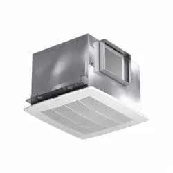
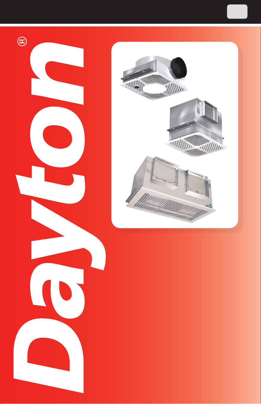
Insulated
Ventilators
465932
Models 60RG34, 60RG35, 60RG36,
60RG39, 60RG40, 60RG41, 60RG42,
60RG43, 5AE75, 60KU32,
5AE77, 60RG45, 60RG46, 5AE80,
60KU34, 6WZN1, 6WZN2, 60KU31,
60KU33, 60KU42, 60KU43, 60KU44

PLEASE READ AND SAVE
THESE INSTRUCTIONS.
READ CAREFULLY
BEFORE ATTEMPTING
TO ASSEMBLE, INSTALL,
OPERATE OR MAINTAIN THE
PRODUCT DESCRIBED.
PROTECT YOURSELF AND
OTHERS BY OBSERVING ALL
SAFETY INFORMATION. FAILURE
TO COMPLY WITH INSTRUCTIONS
COULD RESULT IN PERSONAL
INJURY AND/OR PROPERTY
DAMAGE! RETAIN INSTRUCTIONS
FOR FUTURE REFERENCE.
PLEASE REFER TO BACK COVER
FOR INFORMATION REGARDING
DAYTON’S WARRANTY AND OTHER
IMPORTANT INFORMATION.
Model #: ___________________
Serial #: ___________________
Purch. Date: _______________
Form 5S6856 / Printed in USA
04632 Version 5 3/2022
© 2005 - 2022 Dayton Electric Manufacturing Co.
All Rights Reserved
1
SAFETY /
SPECIFICATIONS
ASSEMBLY /
INSTALLATION
OPERATION TROUBLESHOOTING
MAINTENANCE /
REPAIR
GETTING STARTED
BEFORE YOU BEGIN
Installation, troubleshooting and parts replacement are to
be performed only by qualified personnel in accordance
with all applicable codes and standards, including fire-rated construction.
Electrical Requirements:
Install all wiring, protection and grounding in accordance
with the U.S. National Electrical Code (NEC) and all local
requirements. Follow all local electrical and safety codes, as well as the U.S.
National Electrical Code (NEC) and the Occupational Safety and Health Act
(OSHA).
Tools Needed:
• Lock-Out Tag-Out
• Phillips Screwdriver
• Drill
• Sheet Metal Screws
Recommended Accessories:
• Speed Control (48C172, 48C173, 43Y140, 35YV92-35YV94)
• Non-Lighted (3DPF7-3DPF8) Ceiling Radiation Damper
• 6" Round Duct Connector (6WZP2)
• 8" Round Duct Connector (6WZP3)
UNPACKING
Contents:
• Dayton
®
Insulated Ventilator (1)
• Mounting Brackets with Hardware (2)
• Operating Instructions and Parts Manual (1)
Inspect:
• After unpacking unit, inspect carefully for any damage that may have
occurred during transit. Check for loose, missing, or damaged parts.
Shipping damage claim must be filed with carrier.
• Check all bolts, screws, set-screws, etc. for looseness that may have
occurred during transit. Retighten as required. Rotate wheel by hand
to be sure it turns freely.
• See General Safety Instructions on page 2, and Cautions and
Warnings as shown.
MAINTENANCE /
REPAIR
TROUBLESHOOTING OPERATION
ASSEMBLY /
INSTALLATION
GETTING STARTED
2
SAFETY /
SPECIFICATIONS
GENERAL SAFETY INSTRUCTIONS
Do not depend on any switch as the sole means of
disconnecting power when installing or servicing the fan.
Always disconnect, lock and tag power source before installing or servicing.
Failure to disconnect power source can result in fire, shock or serious injury.
Motor will restart without warning after thermal protector trips. Do not touch
operating motor, it may be hot enough to cause injury.
Do not place any body parts or objects in fan, motor
openings or drives while motor is connected to power
source.
For general ventilating use only. Do not use to exhaust
hazardous or explosive materials and vapors.
To reduce the risk of fire, electric shock, or injury to
persons, observe the following:
1. Read and follow all instructions and cautionary markings. Make sure
electrical power source conforms to requirements of equipment and
local codes.
2. Use this unit only in the manner intended by the manufacturer. If you
have questions, contact the manufacturer.
3. Installation work and electrical wiring must be done by a qualified
person(s) in accordance with all applicable codes and standards,
including fire-rated construction.
4. Sufficient air is needed for proper combustion and exhausting of
gases through the flue (chimney) of fuel burning equipment to prevent
back drafting. Follow the heating equipment manufacture’s guideline
and safety standards such as those published by the National Fire
Protection Association (NFPA), and the American Society for Heating,
Refrigeration and Air Conditioning Engineers (ASHRAE) and the local
code authorities.
5. These fans are not recommended for cooking exhaust applications.
They are designed primarily for low temperature, clean air applications
only. Figure 3, page 6 shows the minimum distance these fans should
be placed in relation to cooking equipment.
6. When cutting or drilling into wall or ceiling, do not damage electrical
wiring or other hidden utilities.
7. Ducted fans must always be vented to the outdoors.
8. If this unit is to be installed over a tub or shower, it must be marked as
appropriate for the application and be connected to a GFCI (Ground
Fault Circuit Interrupter) - protected branch circuit.
9. Suitable for use with solid-state speed controls.
10. Never place a switch where it can be reached from a tub or shower.
11. Fan/Light combination not to be installed in a ceiling thermally insulated
to a value greater than R-40.
12. Before servicing or cleaning unit, switch power off at service panel
3
GETTING STARTED
ASSEMBLY /
INSTALLATION
OPERATION TROUBLESHOOTING
MAINTENANCE /
REPAIR
SAFETY /
SPECIFICATIONS
and lock service disconnecting means to prevent power from being
switched on accidentally. When the service disconnecting means
cannot be locked, securely fasten a prominent warning device, such as
a tag, to the service panel.
SPECIFICATIONS
Max. Inlet Temp. 104°F
Mounting Location Ceiling, Horizontal or Vertical Discharge
Housing Material Galvanized Steel
Agency Compliance UL/cUL 507, AMCA Sound and Air, Energy Star®
NOTE: Models 60RG34, 60RG35, 60RG36, 60RG39, 60RG40, 60RG41, 60RG42, 60RG43
and 60KU42 are acceptable for use over a bathtub or shower when installed in a GFCI
protected branch circuit.
Dayton Electric Mfg. Co. certifies that the ventilators shown herein are licensed
to bear the AMCA seal. The ratings shown are based on tests and procedures
performed in accordance with AMCA Publication 211 and AMCA Publication 311
and comply with the requirements of the AMCA Certified Ratings Program.
Energy Star® Certified models include:
60RG34, 60RG39, 60RG35, 60RG41, 60RG40 and 60RG36
Singlewide 60RG34
60RG35
60RG39
60RG40
60RG36
60RG41
60RG42
60RG43 60KU42
5AE75
6WZN1
60KU31
60KU33
5AE77
6WZN2
Recommended
Ceiling Opening
(inches)
13-1/2 x
10-7/8
13-1/2 x
10-7/8
14-1/4 x
12-1/8
14-1/4 x
12-1/8
18-1/4 x
14-5/8
18-1/4 x
14-5/8
18-1/4 x
14-5/8
Recommended
Duct Sizes
(inches)
6 Dia. 8 x 6 8 x 8 8X8 8 x 8 8 x 8 10 x 8
Recommended
Speed Control
48C172 48C172 48C172
35YV94
43Y140
48C172 35YV94 48C172
Doublewide 60KU32 60KU43 60RG45 60KU44
60RG46
5AE80
60KU34
Recommended
Ceiling Opening
(inches)
23-7/8 x
11-7/8
23-7/8 x
11-7/8
24 x 14-5/8 24 x 14-5/8 24 x 14-5/8
Recommended
Duct Sizes
(inches)
19-1/2 x 8 19-1/2 x 8 18-3/4 x 8 17-7/16 x 8 18-3/4 x 8
Recommended
Speed Control
48C172
35YV94
43Y140
48C172
35YV94
43Y140
48C173
E19455
MAINTENANCE /
REPAIR
TROUBLESHOOTING OPERATION
ASSEMBLY /
INSTALLATION
GETTING STARTED
4
SAFETY /
SPECIFICATIONS
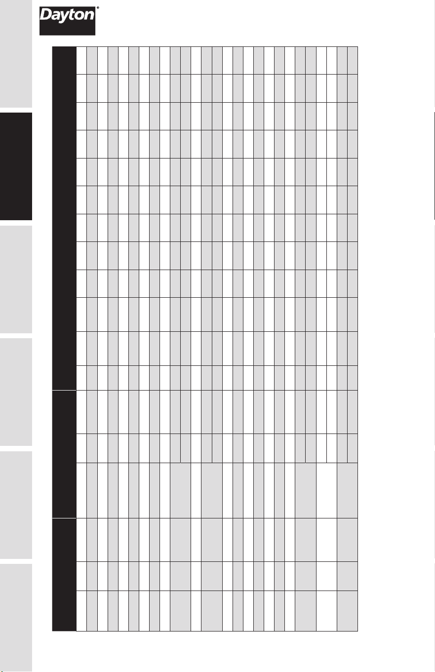
PERFORMANCE
Model
115V Watts
Full Load
Amps
Model
115V – EC Watts
Full Load
Amps RPM
Sones @ 5 Ft. @ CFM Air Delivery @ Static Pressure Shown
.100"SP .250"SP .000" .100" .125" .250" .375" .500" .625" .750" 1.00"
60RG34
16.9 0.14 — — — 870 <0.3 0.4 114 101 98 80 — — — — —
60RG39
19.4 0.16 — — — 950 <0.3 0.5 130 119 115 98 — — — — —
60RG35
23 0.19 — — — 1010 0.4 0.6 144 130 127 109 — — — — —
60RG40
54.2 0.45 — — — 1400 2.5 2 229 214 210 186 156 — — — —
60RG41 56.1 0.47 — — — 900 2 2.5 267 246 242 224 199 162 109 68 —
60RG36 67 0.56 — — — 1000 2.5 3 294 274 271 250 230 201 147 92 —
60RG42 80.7 0.72 — — — 1050 2.5 3 315 293 287 257 231 207 175 124 —
60RG43 135 1.34 — — — 1350 4.5 4.5 410 395 391 368 345 325 307 279 —
6WZN1 121 1.74 — — — 1000 3.5 3 443 413 405 351 306 — — — —
— — — 60KU31
49.1 0.75 850 4.5 3.5 399 354 341 255 — — — — —
155 2.4 1275 8 7.5 604 583 576 540 495 443 377 — —
5AE75 224 3.3 1070 5 4.5 557 512 501 439 392 325 — — —
— — — 60KU33
60.4 0.96 925 4.5 4 441 410 397 327 — — — — —
230 3.39 1450 9.5 9 709 685 677 656 621 580 534 483 —
6WZN2 285 4.4 — — 1080 6 6 752 714 701 653 588 486 320 — —
5AE77 348 3.3 — — — 1600 8.5 8 812 782 775 741 704 665 625 581 —
60KU32 351 2.98 — — — 1015 7 7 790 762 753 728 701 659 621 547 382
60RG45 301 2.78 — — — 1055 5.5 5 971 925 915 866 814 754 694 621 327
60RG46 438 4.05 — — — 1250 7 7 1144 1098 1084 1032 987 935 875 809 561
5AE80 786 7.4 — — — 1450 10 10 1455 1415 1404 1353 1307 1262 1218 1174 —
60KU34 695 6.07 — — — 1695 11.5 11 1559 1518 1503 1456 1402 1346 1300 1239 1095
— — — 60KU42
47 0.7 935 2
2.5 276 251 248 233 215 196 173 146 93
100 1.46 1340 5 5 410 395 390 370 361 349 338 325 294
— — — 60KU43
111 1.82 1275 3.5 3.5 568 527 517 466 419 372 329 275 170
218 3.52 1425 7 7 801 774 766 729 699 666 634 597 530
— — — 60KU44
120 1.94 1050 4 4 838 789 779 735 685 632 579 — —
240 3.75 1225 7.5 7 1162 1106 1092 1023 944 831 668 — —
Performance certified is for installation type B: Free inlet, Ducted outlet. Performance ratings include the effects of an inlet grille and backdraft damper. Speed (RPM)
shown is nominal. Performance is based on actual speed of test. The sound ratings shown are loudness values in fan sones at 5 ft. (1.5 m) in a spherical free field
calculated per AMCA Standard 301. Values shown are for installation type B: Free inlet spherical sone levels.
5
GETTING STARTED
SAFETY /
SPECIFICATIONS
ASSEMBLY /
INSTALLATION
OPERATION TROUBLESHOOTING
MAINTENANCE /
REPAIR
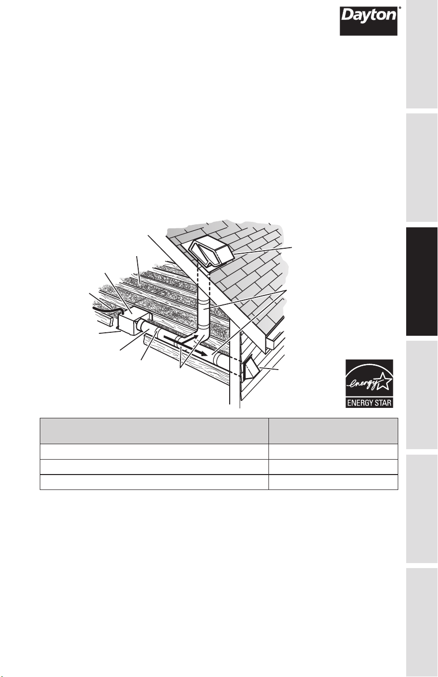
TYPICAL INSTALLATION
The ducting from this fan to the outside of the building has a strong effect on the air flow,
noise and energy use of the fan. Use the shortest, straightest duct routing possible for best
performance, and avoid installing the fan with smaller ducts than recommended. Insulation
around the ducts can reduce energy loss and inhibit mold growth. Fans installed with
existing ducts may not achieve their rated airflow.
Rigid metal duct is recommended for optimal fan performance.
Ensure duct joints and exterior penetrations are sealed with caulk or other similar material
to create an air-tight path and to minimize building heat loss and gain and reduce the
potential for condensation.
Place/wrap insulation around duct and/or fan to in order to minimize possible condensation
buildup within the duct, as well as minimize building heat loss and gain.
*Pu
rchase separately.
INSUL
ATION*
(Place a
round and over Fan Housing.)
ROOF CAP*
(with built-in damper)
FAN HOUSING
POWER CABLE*
ROUND DUCT*
ROUND
ELBOWS*
Seal gaps
around Housing.
Seal duct joints
with tape.
OR
Keep duct
runs short.
WALL CAP*
(with built-in damper)
Energy Star® Certified
Fan Model/Size
Recommended
Duct Dimensions
60RG34 6 inch round
60RG35, 60RG39, 60RG40 8 x 6 inch rectangular
60RG36, 60RG41 8 x 8 inch rectangular
ASSEMBLY /
INSTALLATION
MAINTENANCE /
REPAIR
TROUBLESHOOTING OPERATION
ASSEMBLY /
INSTALLATION
SAFETY /
SPECIFICATIONS
GETTING STARTED
6
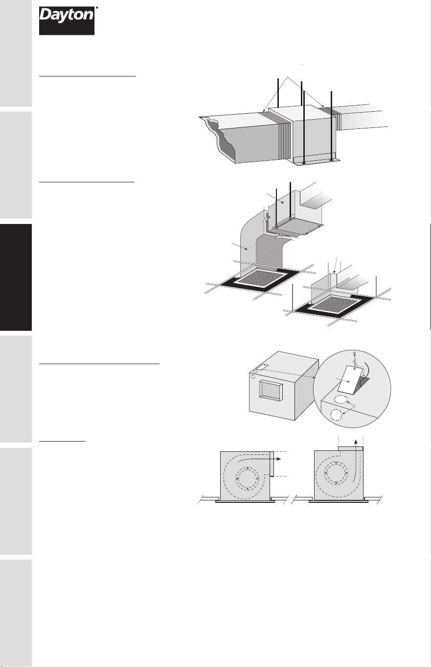
OTHER INSTALLATION CONSIDERATIONS
Ductwork and Noise
Fiberglass ductboard is a better choice
than metal ductwork for reducing fan
noise and is highly recommended for
low sound applications. Where metal
duct is used, sound transmission can be
reduced with flexible duct connections
between the fan and the duct.
Sound and Location
The location of these fans must be taken
into consideration before installation.
In critical sound installations, insulated
ductwork, flexible duct connections or
placing the fan in a remote section of
ductwork are solutions to meeting the
required fan sound levels.
Flex Duct
Connections
Fiberglass
Ductboard
Remote
Mounted
Correct Low
Sound Installation
Incorrect
Fan Mounted
Directly Overhead
Fan Converted
to Inline
PREPARE THE FAN
Remove Wiring Knockout
Remove either top or side wiring knockout,
depending on wiring direction, by bending it back
and forth to break tabs.
Ductwork
Check ductwork to see if the fan’s
discharge requires rotation from
horizontal to vertical discharge.
K
n
o
c
k
o
u
t
s
E
l
ec
t
r
i
ca
l
A
cce
ss
P
a
n
e
l
CSP/SP-C Mounting Arrangements
SP/SP-C Ceiling
Mounting
SP/SP-C Wall
Mounting Arrangements
Airflow
Airflow
Airflow
Airflow
Airflow
AirflowAirflow
Airflow
Airflow
Airflow
ASSEMBLY /
INSTALLATION
7
GETTING STARTED
SAFETY /
SPECIFICATIONS
ASSEMBLY /
INSTALLATION
OPERATION TROUBLESHOOTING
MAINTENANCE /
REPAIR
Fan Rotation
To rotate from horizontal to vertical discharge
A Models Only
Models: 60RG34, 60RG35,
60RG36, 60RG39, 60RG40,
60RG41, 60RG42, 60RG43,
5AE75, 5AE77 , 6WZN1, 6WZN2,
60KU31, 60KU33, 60KU42
Remove the two screws holding
the power assembly in and pull
power assembly out. Rotate
power assembly 180 degrees
and put back into fan. Use the
same screws to reattach power
assembly to fan housing. Flip fan
over and remove the four screws
holding the discharge duct and
damper assembly. Exchange the
assembly with plate mounted on top of fan, as shown in these illustrations.
Models: 60RG45, 60RG46, 5AE80, 60KU32, 60KU34, 60KU43, 60KU44
Remove the eight screws holding the access panel or collar as shown in picture. Rotate the
fan housing so the discharge is facing up. Replace access panel or collar and screws.
Access
Panel
Access
Panel
ASSEMBLY /
INSTALLATION
MAINTENANCE /
REPAIR
TROUBLESHOOTING OPERATION
ASSEMBLY /
INSTALLATION
SAFETY /
SPECIFICATIONS
GETTING STARTED
8
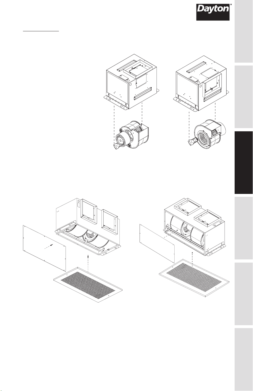
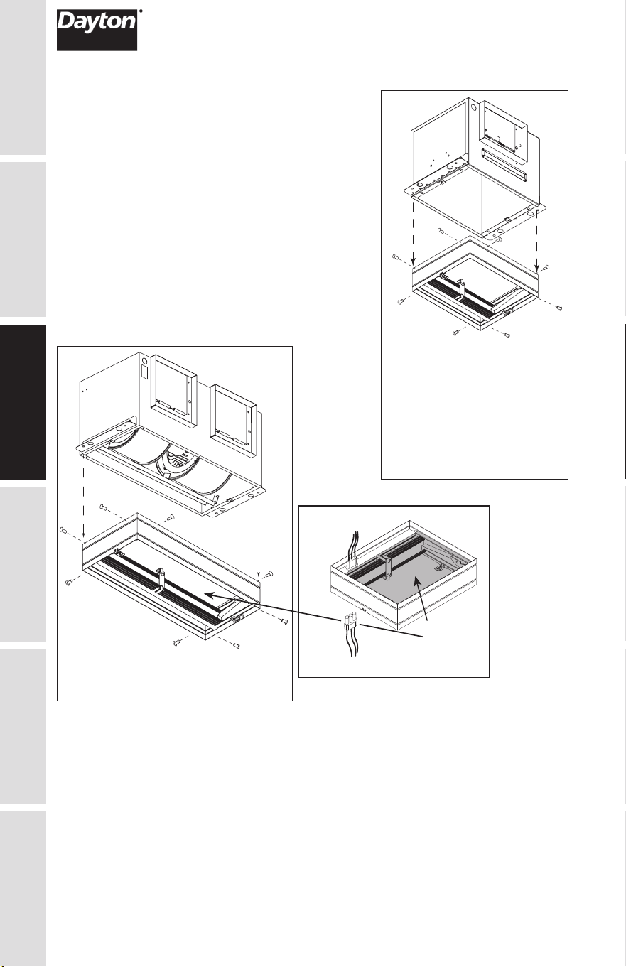
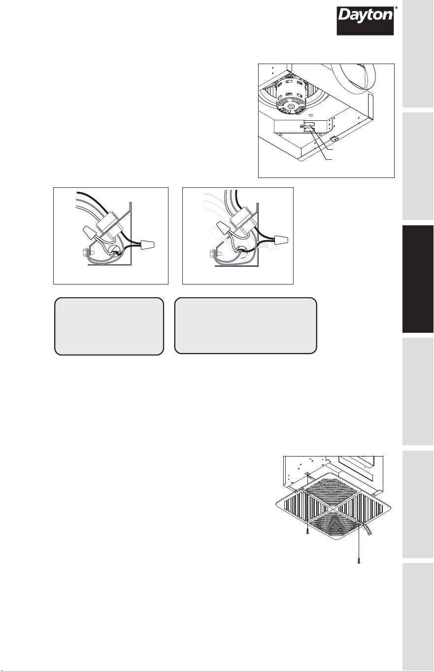
Ceiling Radiation Damper (CRD)
If fan is to be used in a fire resistive membrane ceiling,
a ceiling radiation damper must be used.
If the ceiling radiation damper is already mounted to the
fan from the factory, proceed to Install the Fan.
To mount the ceiling radiation damper to fan, make sure
grille attachment tabs are facing down. Then place the
inlet part of the fan into the ceiling radiation damper
collar, and use self-tapping sheet metal screws (by
others) to screw through the damper collar and into the
fan housing. If the fan/light combination is being used,
make sure ceiling radiation damper has an electrical
plug in it. The electrical plug must be inserted into the
fan. Make sure the electrical wire will not interfere with
damper operation as shown in figure below.
Models: 60RG34, 60RG35,
60RG36, 60RG39, 60RG40,
60RG41, 60RG42, 60RG43,
5AE75, 5AE77 ,6WZN1,
6WZN2, 60KU31,
60KU33, 60KU42
Wires from lighted grille
Wires to ceiling fan
Do not allow
interference
in this area
Models: 60RG45, 60RG46, 5AE80,
60KU32, 60KU34, 60KU43, 60KU44
ASSEMBLY /
INSTALLATION
9
GETTING STARTED
SAFETY /
SPECIFICATIONS
ASSEMBLY /
INSTALLATION
OPERATION TROUBLESHOOTING
MAINTENANCE /
REPAIR
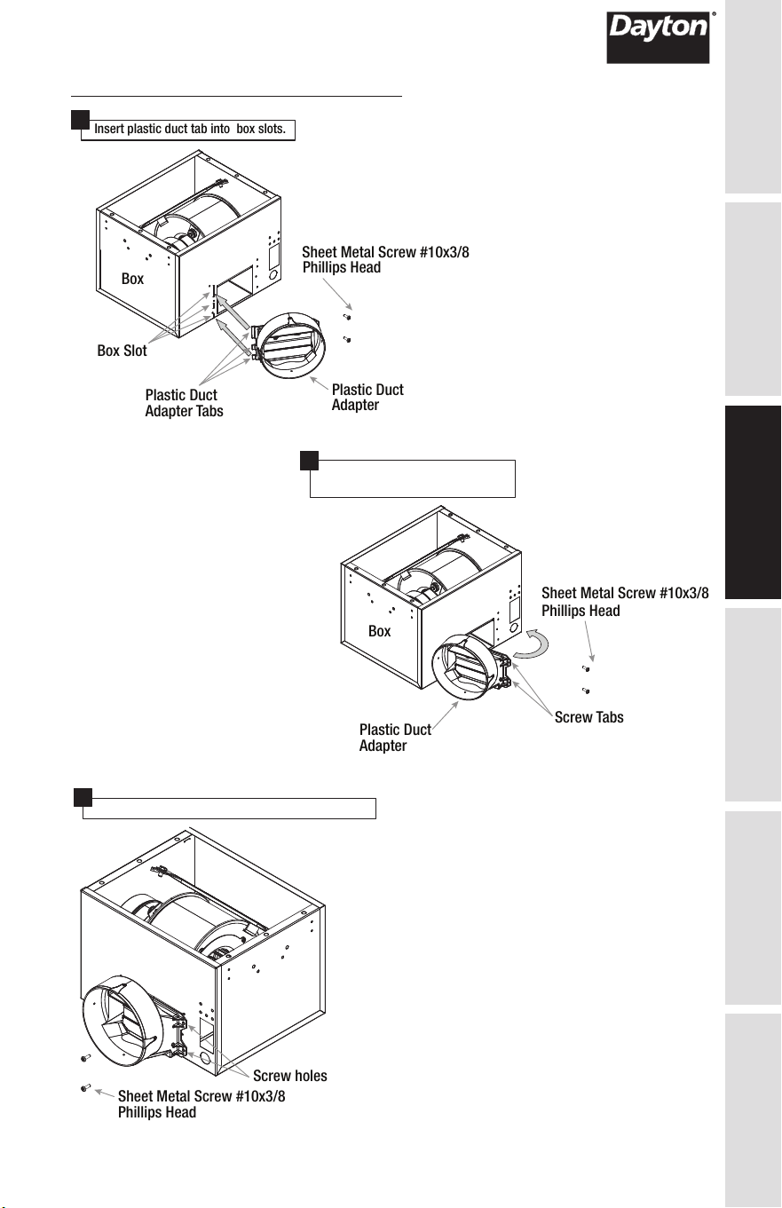
Discharge Installation 60RG34 Models
Box Slot
Plastic Duct
Adapter Tabs
Insert plastic duct tab into box slots.
Plastic Duct
Adapter
Sheet Metal Screw #10x3/8
Phillips Head
Box
Sheet Metal Screw #10x3/8
Phillips Head
Box
Plastic Duct
Adapter
Screw Tabs
Sheet Metal Screw #10x3/8
Phillips Head
Screw holes
Rotate plastic duct adapter until the
screw tabs meet the box.
1
2
Install screws provided to secure discharge.
3
ASSEMBLY /
INSTALLATION
MAINTENANCE /
REPAIR
TROUBLESHOOTING OPERATION
ASSEMBLY /
INSTALLATION
SAFETY /
SPECIFICATIONS
GETTING STARTED
10
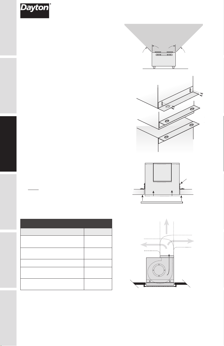
INSTALLATION INSTRUCTIONS
1. For best performance, choose a location with
the shortest possible duct run and minimum
number of elbows. Do not mount near cooking
equipment, as shown in Fig. 1.
2. Attach adjustable mounting brackets to fan,
but leave the screws loose until proper height
is determined, shown in Fig. 2. Cut hole to
dimensions shown in table below.
For Frame Construction:
Position unit between joists. Position brackets
such that bottom edge of housing will be flush
with finished ceiling, and tighten the adjustable
mounting brackets, shown in Fig. 3.
3. Installation of ductwork is critical to the
performance of the fan, shown in Fig.4. Straight
ductwork (1) or ductwork that turns in the same
direction as the wheel (2) is recommended.
Ductwork turning opposite the wheel direction
(3) will cause turbulence and back pressure
resulting in poor performance.
4. Slide ductwork over the fan’s discharge collar
and securely attach it with sheet metal screws.
Make sure the screws do not interfere with
damper operation. Check damper to make
sure it opens freely.
Note: Model 60RG34 is standard with a round
duct. Should any model require a round duct,
Round Duct Connector (6WZP3 or 6WZP2)
may be ordered from manufacturer for eld
installation.
Slots in the
brackets
allow fine
adjustment
for flush
fit with
wall/ceiling
opening
Top Mount
Bottom Mount
Brackets can be
used in either
position to adapt to
most mounting
situations
Bottom Mount
Figure 2
45° 45°
Do not install
fan in this area
Figure 1
Ceiling Openings
Ceiling Exhaust Sizes Fan/CRD
60RG34, 60RG35, 60RG39,
60RG40
11
1
⁄8
x 13
7
⁄16
60RG36, 60RG41, 60RG42,
60RG43, 60KU42
12
1
⁄4
x 14
3
⁄8
60KU32, 60KU43 24
1
⁄8
x 12
1
⁄4
5AE75, 5AE77, 6WZN1,
6WZN2, 60KU31, 60KU33
14
7
⁄8
x 18
7
⁄16
60RG45, 60RG46, 5AE80,
60KU34, 60KU44
14
7
⁄8
x 24
1
⁄8
Slots in the
brackets
allow fine
adjustment
for flush
fit with
wall/ceiling
opening
Top Mount
Bottom Mount
Brackets can be
used in either
position to adapt to
most mounting
situations
Bottom Mount
AIRFLOW
1
(GOOD)
3
(POOR)
2
(GOOD)
Figure 3
Figure 4
ASSEMBLY /
INSTALLATION
11
GETTING STARTED
SAFETY /
SPECIFICATIONS
ASSEMBLY /
INSTALLATION
OPERATION TROUBLESHOOTING
MAINTENANCE /
REPAIR
WIRE THE FAN
1. Remove wiring cover. If fan/accessory
combination is being used, make sure the
fan plug is connected to the fan receptacle
and the accessory plug is connected to the
accessory receptacle, shown in Fig. 5. Using
proper wire connectors, wire the fan as
shown in Fig. 6a. For wiring of light
proceed to Fig. 6b.
2. Push all wiring into the unit’s cover and
replace wiring cover.
115 & 277 Volt
Black wire is “Hot”
White wire is “Neutral”
Green wire is “Ground”
220 - 240 Volt
Black wire is “Hot”
White wire is “Hot”
Green wire is “Neutral/Ground”
Figure 6a
Fan, No Light Fan and Light
Figure 6b
Fan, No Light Fan and Light
Figure 5
Fan Outlet (top)
Accessory (bottom)
Fan
Light
ASSEMBLY /
INSTALLATION
Figure 7
ATTACH THE GRILLE
1. Attach grille with two screws provided. Make
sure not to over tighten; over tightening will
damage grille.
2. Slide attachment screw covers over the
attachment screws, shown in Figure 7.
MAINTENANCE /
REPAIR
TROUBLESHOOTING OPERATION
ASSEMBLY /
INSTALLATION
SAFETY /
SPECIFICATIONS
GETTING STARTED
12
TROUBLESHOOTING GUIDE
Symptom Possible Cause(s) Corrective Action
Ventilator
inoperative
1. Blown fuse or breaker 1. Replace or repair
2. Defective motor 2. Replace or repair
3. Incorrectly wired 3. Shut power OFF and check
wiring for proper connections
Excessive noise
or vibration
1. Accumulation of material on
wheel
1. Clean
2. Fan wheel out of balance 2. Replace wheel
Insufficient airflow 1. Blocked duct or clogged filters 1. Clean or replace
2. Collapsed or perforated duct 2. Repair or replace duct section
Motor overloads
or overheats
1. Shorted motor winding 1. Replace motor
2. Incorrect voltage input 2. Correct to 115V
3. Buildup of dust, dirt or other
contaminants on motor
3. Clean motor
MAINTENANCE
Disconnect the power source before working on the unit.
Maintenance should be done yearly or as conditions
warrant.
1. The ventilator motor, wheel, housing and grille should be checked
for dust and dirt accumulations. Dirt buildup can lead to loss of
performance and motor overheating.
a. Remove grille. Using a vacuum cleaner with appropriate
attachments, vacuum dust from grille. Wash grille with warm,
soapy solution of water. Allow grille to dry thoroughly before
re-installing.
b. To clean wheel and housing, unplug motor from the integral
terminal box. Vacuum the wheel. If necessary, the wheel can be
washed. Wipe the wheel dry with an absorbent cloth. Wipe out the
interior of the housing. Plug blower motor into terminal box.
c. Lubricate only those motors which a have an oil hole provided.
A few drops of all purpose oil (SAE 20) will be sufficient.
MAINTENANCE /
REPAIR
TROUBLESHOOTING OPERATION
ASSEMBLY /
INSTALLATION
SAFETY /
SPECIFICATIONS
GETTING STARTED
14
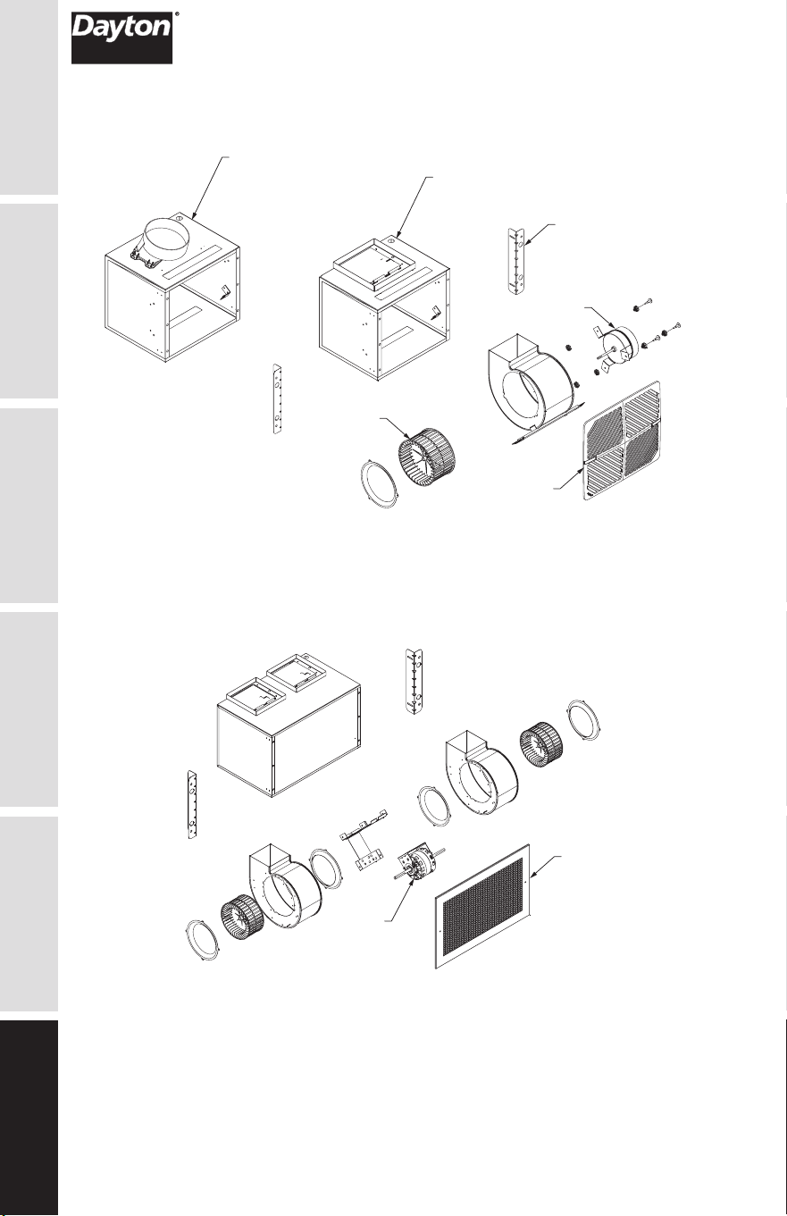
REPAIR PARTS ILLUSTRATION FOR SINGLEWIDE
INSULATED VENTILATORS
4
3
2
1
36WG64, 36WG65, 3DPE5C,
3DPE6A, 5AE70C, 60RG40, 60RG41,
60RG42, 5AE75 and 5AE77
3
5
4
2
1
Model 60RG34 only
REPAIR PARTS ILLUSTRATION FOR DOUBLEWIDE
INSULATED VENTILATORS
2
1
For Repair Parts, call 1-800-Grainger
24 hours a day – 365 days a year
Please provide following information:
-Model number
-Serial number (if any)
-Part description and number as shown in parts list

15
GETTING STARTED
SAFETY /
SPECIFICATIONS
ASSEMBLY /
INSTALLATION
OPERATION TROUBLESHOOTING
MAINTENANCE /
REPAIR
Ref.
No. Description
Part Number for Models:
60RG34 60RG35 60RG36 60RG39 60RG40 Qty
1 Wheel 21EC04 21EC04 21EC05 21EC04 21EC04 1
2 Motor 21DY26 21DY27 21DY28 21EC38 34G193 1
3
Mounting
Bracket Kit
21EA91 21EA91 21EA92 21EA91 21EA91 1
4 Grille 793K37 793K37 793K37 793K37 793K37 1
Ref.
No. Description
Part Number for Models:
60RG41 60RG42 60RG43 5AE75
5AE77
Qty
1 Wheel 21EC05 21EC05 21EC05 21EC06 21EC06 1
2 Motor 21EC10 21EC40 21EC11 21EC41 21DV64 1
3
Mounting
Bracket Kit
21EA92 21EA92 21EA92 21EA93 21EA93 1
4 Grille 793K37 793K37 793K37 21EA87 21EA87 1
Ref.
No. Description
Part Number for Models:
6WZN1 6WZN2 60KU31 60KU33 60KU42
Qty
1 Wheel 21DV70 21DV69 21EC06 21EC06 21EC05 1
2 Motor 21DV63 21DV62 60YG51 60YG52 60YG53 1
3
Mounting
Bracket Kit
21EA93 21EA93 21EA93 21EA93 21EA92 1
4 Grille 21EA87 21EA87 21EA87 21EA87 793K37 1
REPAIR PARTS LIST FOR SINGLEWIDE
INSULATED VENTILATORS
Ref.
No. Description
Part Number for Models:
60KU32 60RG45 60RG46 5AE80 60KU34 Qty
1 Motor 21EC12 21EC42 21EC43 21EC44 21EC45 1
2 Grille 21EA89 21EA88 21EA88 21EA88 21EA88 1
Ref.
No. Description
Part Number for Models:
60KU43 60KU44 Qty
1 Motor 60YG54 60YG55 1
2 Grille 21EA89 21EA88 1
† Includes (2) scrolls and motor bracket fully assembled, requires purchase of (2)
wheels if needed.
REPAIR PARTS LIST FOR DOUBLEWIDE
INSULATED VENTILATORS
