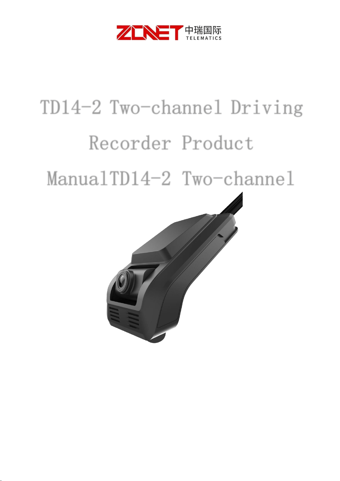
TD14-2 Two-channel Driving
Recorder Product
ManualTD14-2 Two-channel
Driving Recorder Product

I. Product Introduction
This device is an intelligent terminal product integrating multiple advanced
functions such as GPS/BDS positioning monitoring, 4G remote real-time video
surveillance, local TF card recording, and DMS/ADAS AI voice alerts. It organically
combines functions including real-time monitoring, operation management, and
command and dispatch into one unit. It is a cost-effective product specifically
developed for in-vehicle video surveillance and remote monitoring. It adopts
domestic intelligent image chips and an embedded operating system, combined
with the most advanced H.265 video compression/decompression technology,
network technology, and GPS/BD positioning technology in the IT field. It supports
up to 2-channel 1080P HD video surveillance recording and playback; 1-channel
audio input/output. The proprietary pre-allocated vehicle-specific file system
technology solves the file fragmentation problem caused by repeated read/write,
and prevents storage file system crashes, data loss, failure to detect the storage, and
file garbling, ensuring stable and complete data; it records vehicle driving
information and uploads data wirelessly, and together with the center software
enables alarm-linked central monitoring, remote management, and playback
analysis based on the central database. The product features a simple appearance
and flexible, convenient installation.
II. Usage Precautions

To ensure the safe use of the terminal device and extend its service life, please
fully consider the following factors during installation:
1. After receiving the product, inspect the device and accessories. If any item in
the package is damaged or any accessory is missing, please contact your dealer
promptly.
2. When installing and operating the device, comply with relevant electronic
product specifications as well as the requirements of the vehicle and other
connected equipment.
3. Installation and construction must comply with relevant standards; relevant
national or local standards may be referenced.
4. Check the input power voltage; it must be within the 10-36V range. The
recommended operating voltage is 12V or 24V to prevent device malfunction
caused by voltage mismatch.
5. For optimal positioning performance, the receiving surface of the GPS
antenna must face upward with no metal objects above it. The bottom of the
antenna must remain flat, the tilt angle must not exceed 30 degrees, and the
distance from the device should be approximately 50 cm. Place the positioning
antenna as close as possible to the junction of the dashboard and the windshield.
6. The vehicle recorder should operate within the temperature and humidity
ranges specified in the technical specifications.
7. The device's external wiring should have sufficient spacing and be protected
with flame-retardant conduit to ensure the cables will not cause leakage due to wear
or aging.
III. Product Appearance, Features and Specifications
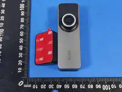
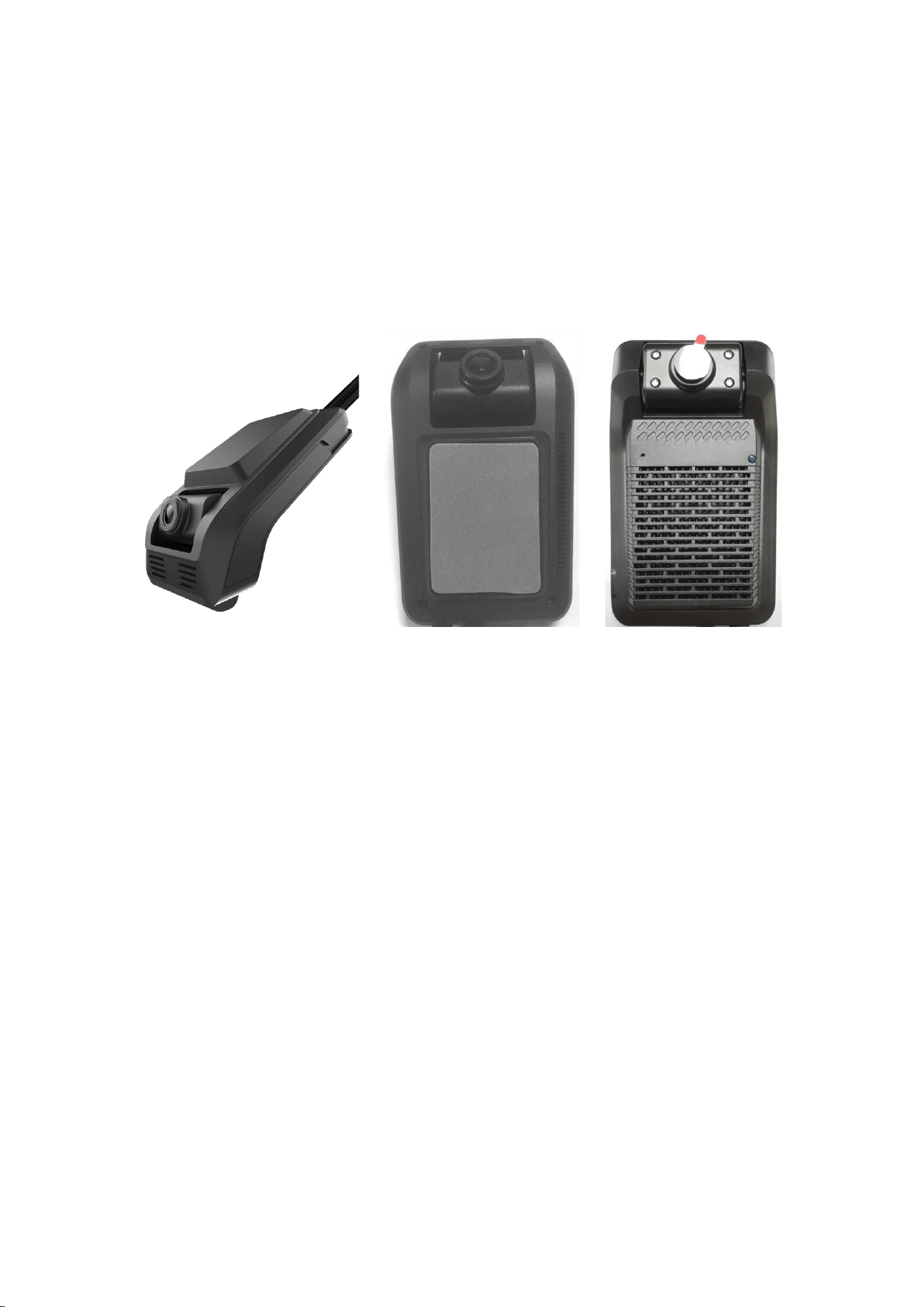
Side Front Back
Product Features
➢ Adopts H.265 & H.264 codec, saving storage space and transmission
bandwidth;
➢ Built-in real-time codec for 2 channels of 1080P*25FPS, 720P, D1, etc.;
➢ Built-in dual-channel AI intelligent algorithms, supporting ADAS and DMS
functions;
➢ Supports GPS + BDS dual-mode precise positioning;
➢ Supports 1 TF card and a supercapacitor to doubly guarantee the integrity of
recording files;
➢ Supports 1 SIM card; the 4G module optionally supports global frequency
bands; supports Wi-Fi hotspot;
➢ 1-channel IO output (low level);
➢ 1-channel RS232 serial port;
➢ Built-in speaker and microphone, supporting two-way voice intercom
between the device and the platform;
➢ One-touch SOS emergency call;
➢ Supports video preview and parameter configuration via mobile APP, client
software, and platform software;
➢ Dedicated file system improves disk read/write efficiency and makes
recording more stable;
Product parameters
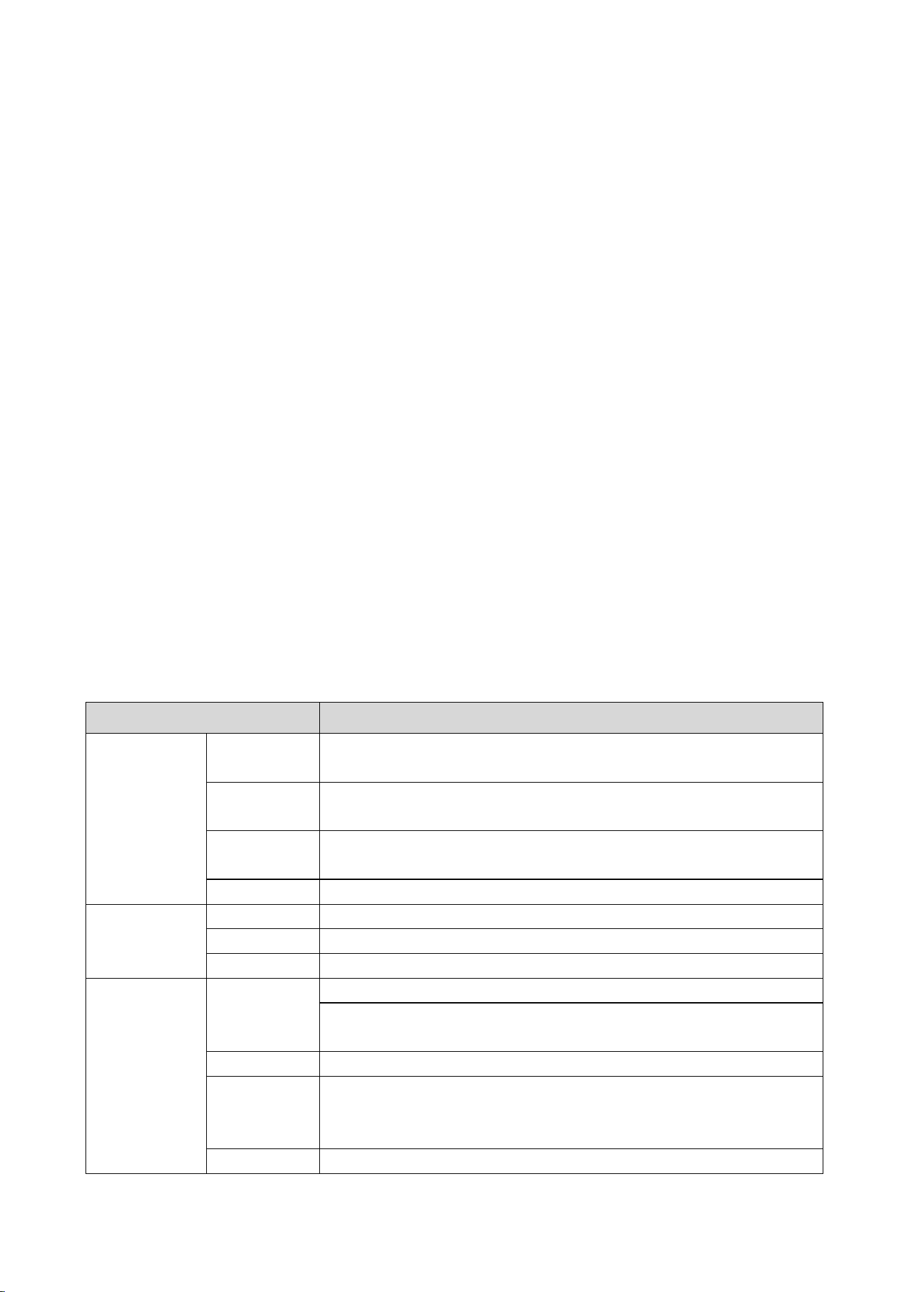
Item
Parameter
System
Operating
Language
Chinese / English
Operating
System
Linux
Operation
Interface
Supports APP operation interface;
GUI
None;
Processor and
CPU
CPU
ARM Cortex-A7 MP2@950MHz
Memory
DDR3 2Gb
Flash
1Gb
Video and
Recording
System
Video Input
Resolution: front 1080P, rear 1080P. Max 1080P 60 fps
Front 1080P sensor, horizontal angle 115°
Rear 1080P sensor, horizontal angle 115
°
, with Ir-cut infrared night vision
Video Standard
PAL standard, NTSC standard
Video
Compression
Format
H.264/H.265 compression format
Preview
Supports 1080P, 720P, D1 selectable,

Function
Recording
Resolution
1 to 8 quality levels, best level 1, lowest level 8
Recording
Quality
1 to 8 quality levels, best level 1, lowest level 8
Recording
Rate
PAL: 100 fps, CCIR625 line, 50 fields
NTSC: 120 fps, CCIR525 line, 60 fields;
CIF: 256Kbps ~ 1.5Mbps, multiple quality levels selectable
HD1: 600Kbps ~ 2.5Mbps, multiple quality levels selectable
D1: 800Kbps ~ 3Mbps, multiple quality levels selectable
720P: 1Mbps-4Mbps, multiple quality levels selectable
1080P: 1Mbps~8Mbps, multiple quality levels selectable
2K: 2Mbps~16Mbps, multiple quality levels selectable
Recording
Mode
Automatic recording by default, supports power-on recording, scheduled
recording, alarm recording, etc.
Audio
Audio Input
1-channel audio, built-in MIC
Audio Output
1 channel, built-in speaker
Compression
Format
G.711A compression format
Recording
Method
Audio and video recorded synchronously
Alarm Input
1-channel IO input (emergency alarm button);
Alarm Output
1-channel IO output (low level), for remote vehicle lock (optional)
Communication Interface
1-channel RS232 (optional)
GPS Positioning
Supports GPS / BD (external Gmouse, TTL level interface)
Reset Button
3 seconds to restore Wi-Fi, 8 seconds to restore factory settings;
Sensor
Built-in 3-axis acceleration
Storage
TF Card
Supports, maximum 512G
Upgrade
Method
Supports TF card upgrade, FTP remote automatic upgrade
Storage
Method
Proprietary raw-disk storage method
SIM Card
Interface
1 Micro SIM card interface
AI
ADAS
Lane departure, pedestrian, and vehicle distance detection, etc.
DSM
Fatigued driving detection, smoking, and obstruction unsafe driving
behavior detection
Low Power
Consumption
Sleep Online
Supports low-power online reporting to platform function
Vibration
Wake-up
Supports vibration-triggered wake-up in low-power standby mode
Power and
Consumption
Power
Management
Adaptive wide-range power input, with overload, under-voltage, short-circuit,
reverse-connection and other protection functions; supports scheduled
power on/off and delayed shutdown functions.
Input Voltage
DC:+9V ~ +36V
Output Voltage
+5V@500mA
Power
Consumption
Normal operating state < 5W (without peripherals)
Operating
Environment
Temperature
-25℃ to +70℃
Humidity
20% to 80%
Security
Management
Password
Access
Two-level management with user password and administrator password
Platform Access
JT/T808-2013, JT/T808-2019, JT/T905-2014 (optional support)
JT/T1076-2016, JT/T1078-2016
CMSV6
Dimensions
120mm*77mm*55mm
Net Weight
240g
IV. Accessories and Interface Definitions
1. Product and Accessory Inspection
Before using this product, please check whether the product is damaged and
whether the accessories are complete. If anything is missing, please contact your
supplier.
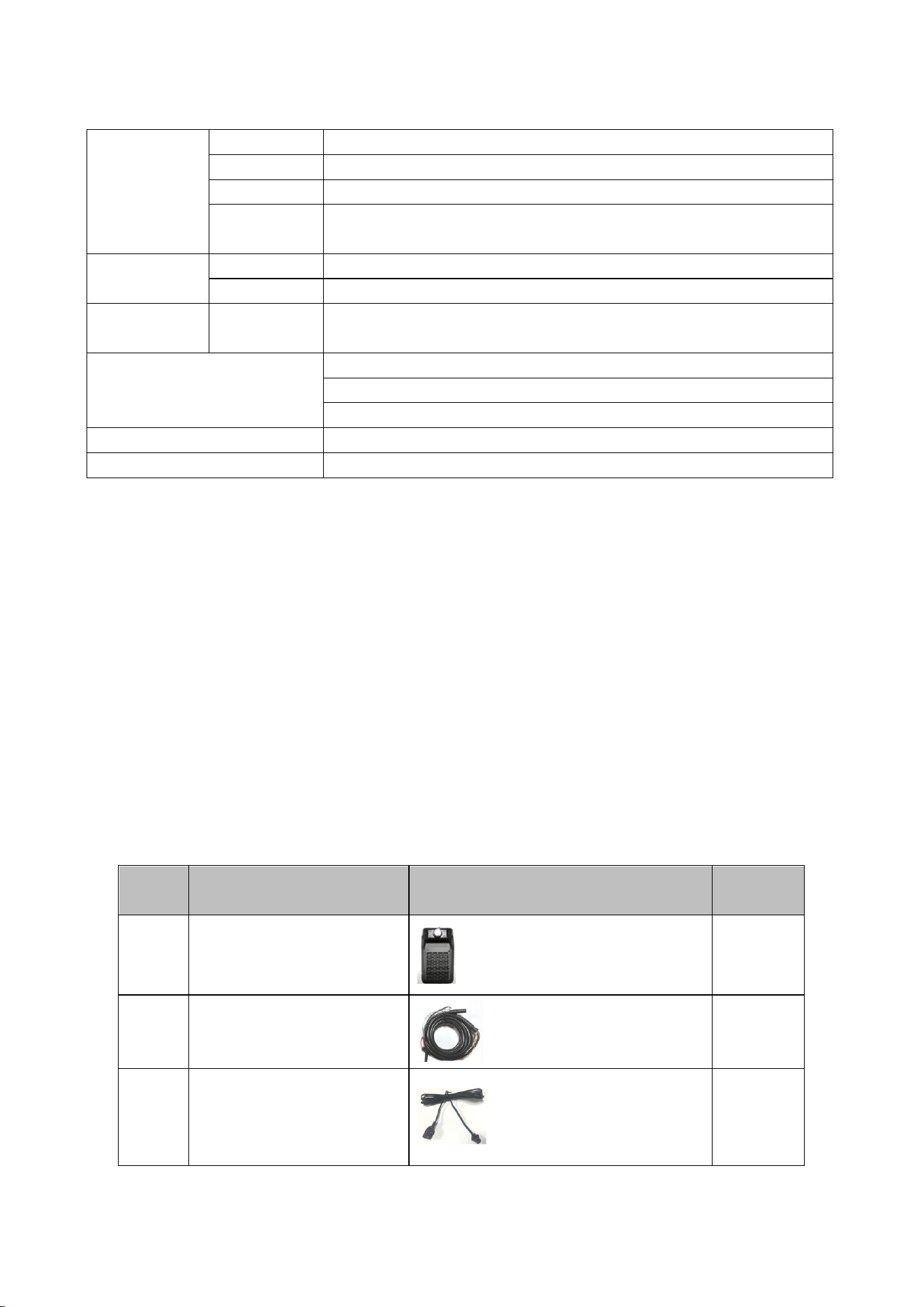
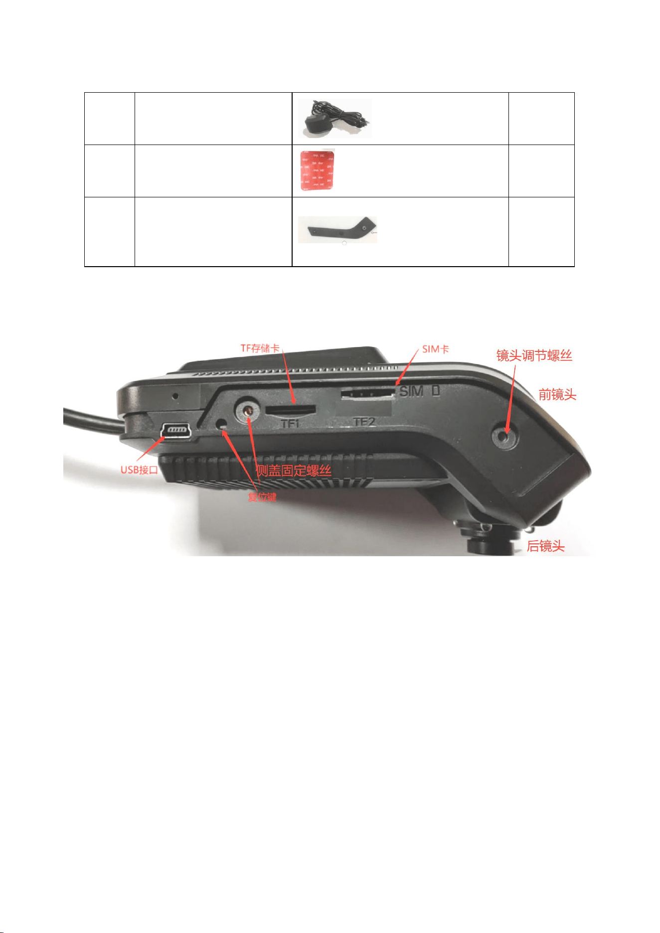
The product and accessory list is as follows:
Table 2. Product Accessories List
No.
Name
Image
Qty
1
Main Unit
1
2
Power Cable
1
3
SOS One-touch Alarm
Cable
1
4
BD/GPS Antenna
1
5
3M Adhesive
1
6
Side Cover Screw Tool
Kit
1
2. Panel Introduction
Figure 1. Product Interface Diagram
3. Cable Interface Connection Methods
This mainly introduces the definitions of interfaces such as power, ACC, GPS,
RS232, IO-out, and SOS alarm, as detailed below:
3.1 Internal Cable Interface
Connect the internal cable and the power extension cable, as detailed below:
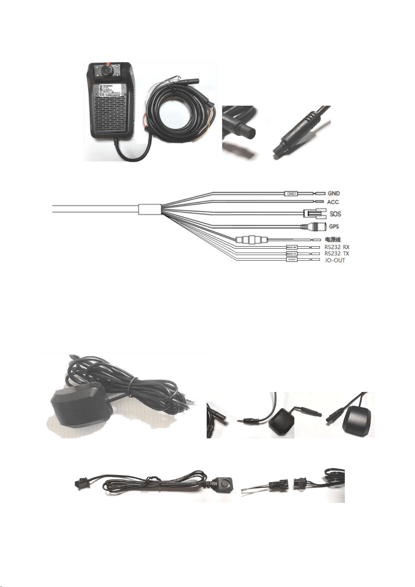
Figure 2. Power Cable Interface Function Definition
3.2 Accessory Cable Interface Connection Methods
Figure 3. GPS Cable 3.5mm headphone jack interface or 4P BMW interface
Figure 4. SOS Alarm Cable 2P plug-in interface
V. Installation Instructions
TF card selection: It is recommended to choose a well-known brand and
high-quality TF card. A TF card of Class 10 or above is recommended, with a
capacity between 8G and 128G.
TF card formatting: After obtaining a new TF card, if there is data on it that
needs to be backed up, please back it up first. Once backed up, the device will
automatically format the new card, and it can only be used after formatting is
complete.
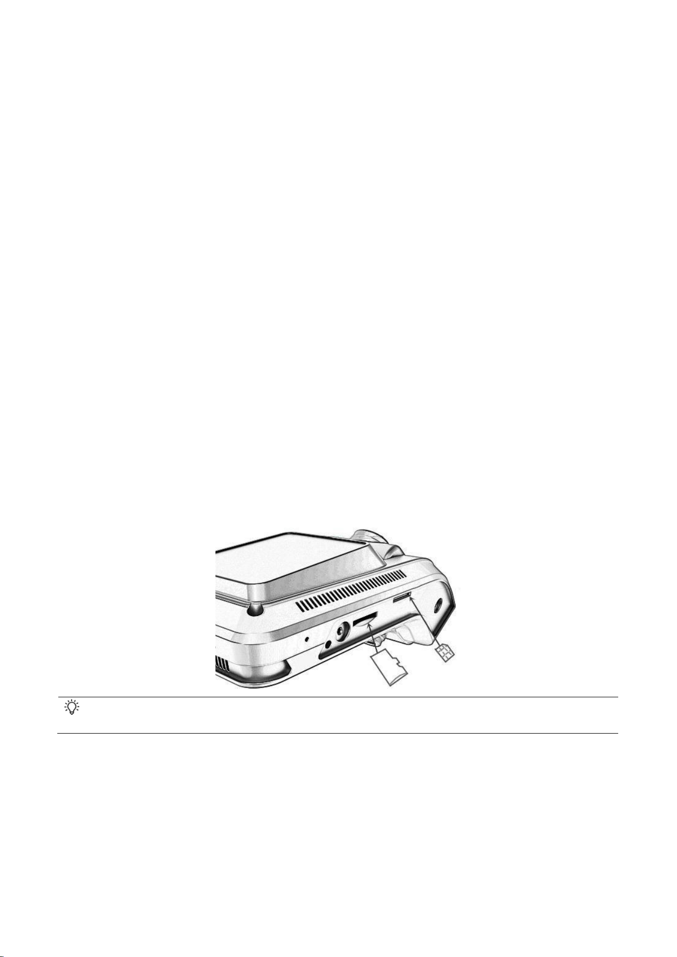
1. Install the 4G Card and TF Card First
Remove the side protective cover and insert the 4G card (Micro SIM card) and
the recording storage card (TF card).
When inserting the SIM card or TF card, if there is spring resistance and a latch clicks into place, the card is
successfully installed.
Install the tamper-proof protection plate and its screws, and secure the lens at
the same time. The specific accessories and the diagram are shown below.
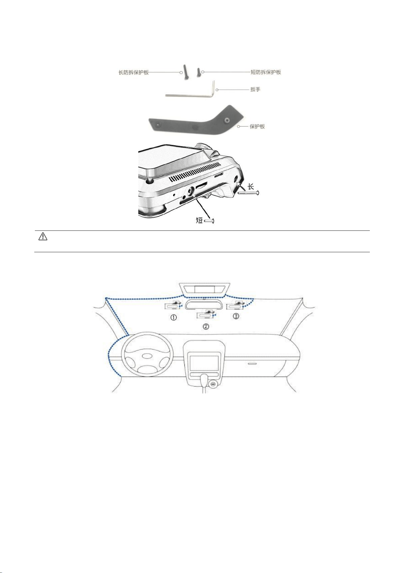
Note: The short tamper-proof plate screw goes into the fixing hole next to the reset button, and the long
tamper-proof plate screw goes into the fixing hole near the camera.
2. Select the Installation Position
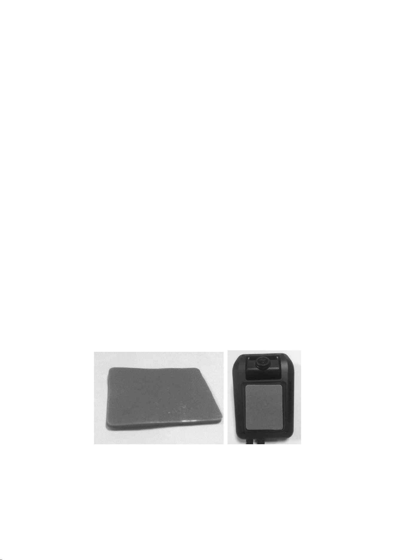
Recommended Installation Position Diagram
Please note the following points during installation:
① Waterproofing: Choose a location that is not prone to water ingress to keep
the terminal dry. Keep away from air-conditioner outlets to prevent
condensation from accumulating inside the terminal due to temperature
differences, which would affect the product's service life.
② Shockproofing: The terminal must not be installed suspended in a position
subject to prolonged severe vibration.
③ Interference protection: The terminal should be kept away from in-vehicle
audio/video, intercom, and other electronic devices to prevent conducted and
radiated interference.
3. Fixed Installation and Commissioning
Install the dust-free adhesive sticker: Before installing the main unit, clean
the windshield at the intended mounting position to prevent the sticker from
falling off due to poor adhesion. First attach the 3M adhesive to the device, find
the proper installation angle inside the vehicle, peel off the 3M dust-free
adhesive paper from the bracket, pay attention to the installation direction, and
stick the device with the 3M adhesive onto the vehicle's front windshield.
Adjust the angle of the recorder lens: Adjust the recorder camera and move
the recorder as required to ensure the front camera faces straight ahead of the
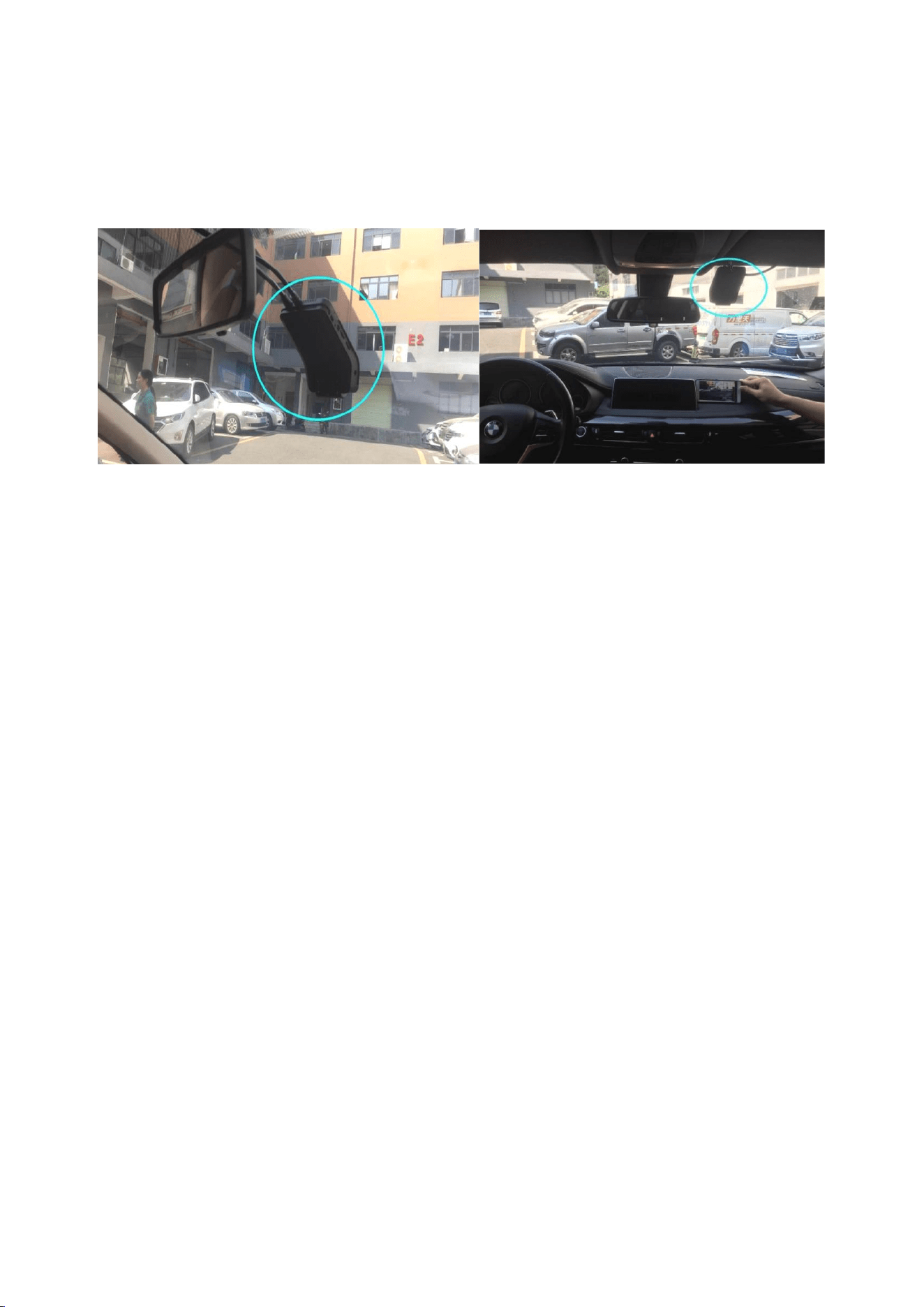
vehicle. The rear camera can be adjusted according to personal needs and actual
conditions, as shown in the figure:
4. Antenna Installation and Wiring
Take the external GPS antenna out of the accessory box and connect the GPS
antenna correctly. For optimal positioning performance, the receiving surface of
the positioning antenna must face upward with no metal objects above it, and the
bottom of the antenna must remain flat with a tilt angle not exceeding 30 degrees.
Keep the antenna at least 50 cm from the device, and place it as close as possible
to the junction of the dashboard and the windshield.
For wiring, the user may refer to '2. Recommended Installation Position
Diagram' (subject to the user's actual conditions). ①②③ are reference positions
for device installation; please wire according to actual conditions. If the main unit
has built-in front and rear dual cameras, positions ①② are recommended; if only
a front camera is available, positions ②③ are more suitable. Concealed wiring is
recommended.
5. Power Connection

Follow the blue wiring in the 'Recommended Installation Position Diagram' to
connect to the in-vehicle fuse control box, and find the corresponding signal wires
to connect with the device wiring (ACC, ground, constant power, left/right turn
signal wires, etc.). Connect according to the power cable interface definition. Before
connecting, check that the input voltage is within 10-36V, with a recommended
operating voltage of 12V or 24V, to prevent device malfunction caused by voltage
mismatch.
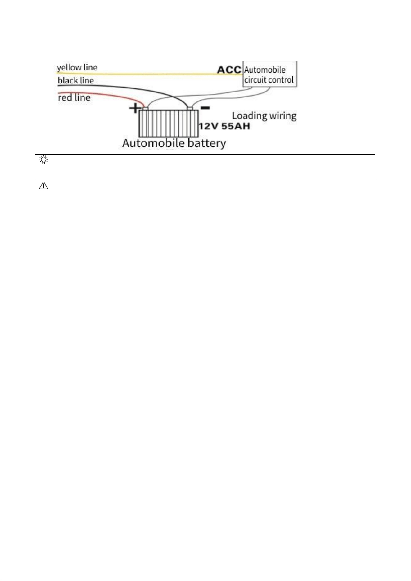
Connect the red power wire (positive) to the vehicle's constant power, i.e., the
positive terminal of the vehicle's main control power supply.
The black power wire (negative) should be connected to the vehicle power
negative terminal or ground; ensure good conductivity at the grounding point.
The yellow power wire (ignition) ACC switch (the gear switch before the vehicle
starter motor) should be connected to the ignition control cable, i.e., the circuit that
is powered only when the vehicle is running.
When the vehicle key is turned on, the device will start automatically; when the
vehicle key is turned off, it will shut down automatically.
When debugging the device with a power adapter, you may connect the red and
yellow wires together to the positive terminal of the power supply.
After connecting the power, the working indicator light will illuminate when the recorder is operating, and
a startup sound will be emitted from the speaker hole.
Users must not reverse the positive and negative terminals.
6. Camera Angle Adjustment during Installation
DSM/ADAS function: This function issues alarms for irregular driving such as
fatigued driving and lane departure. When the driver yawns, closes eyes, smokes,
uses a phone, makes a call, or engages in other irregular driving behaviors, the
function will trigger a voice alarm and report the alarm information.
6.1 ADAS Front Camera
Installation position: Try to center it on the windshield as the axis, moving up or
down depending on the vehicle type. For a steeply sloped windshield, install it
slightly above the center; for a vertical windshield, install it slightly below the center.
(Note: It must not be affected by the wiper.)
The ADAS camera is embedded in the main unit. After securing the main unit,
only the ADAS camera angle needs to be adjusted. Power on the main unit and use
the APP to view the image ratio: the road surface should occupy 1/2-2/3 of the
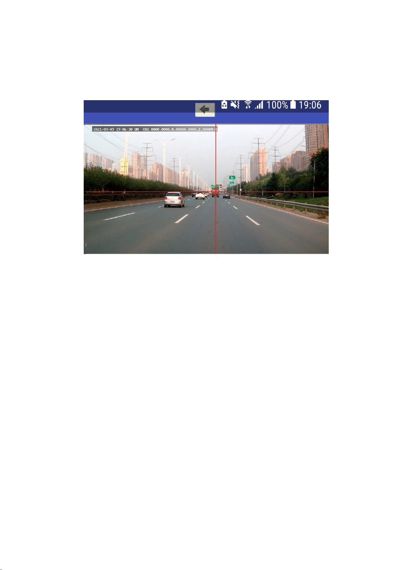
image and the sky 1/2-1/3 of the whole image, as shown in the effect diagram below.
After adjusting the angle, use a tool to secure the camera.
When performing ADAS calibration with the APP, drive the vehicle straight in the
middle of the lane. The vertical line is the lane centerline, and the horizontal line is
the level of the vanishing point ahead; place the crosshair at the intersection and
adjust using up/down/left/right, then click 'Start Calibration' once calibrated.
6.2 DSM Rear Camera (supports infrared night vision)
1. Height requirement: 10-15 cm below the driver's eye level (the camera should
have a slightly upward tilt, as if looking up toward the driver's eyes, which yields
better fatigue detection results).
2. Distance requirement: Within 70 cm-100 cm from the driver's head.
3. Angle requirement: Adjust the camera angle via video so that the driver's face
is clearly and completely visible on one side of the video.
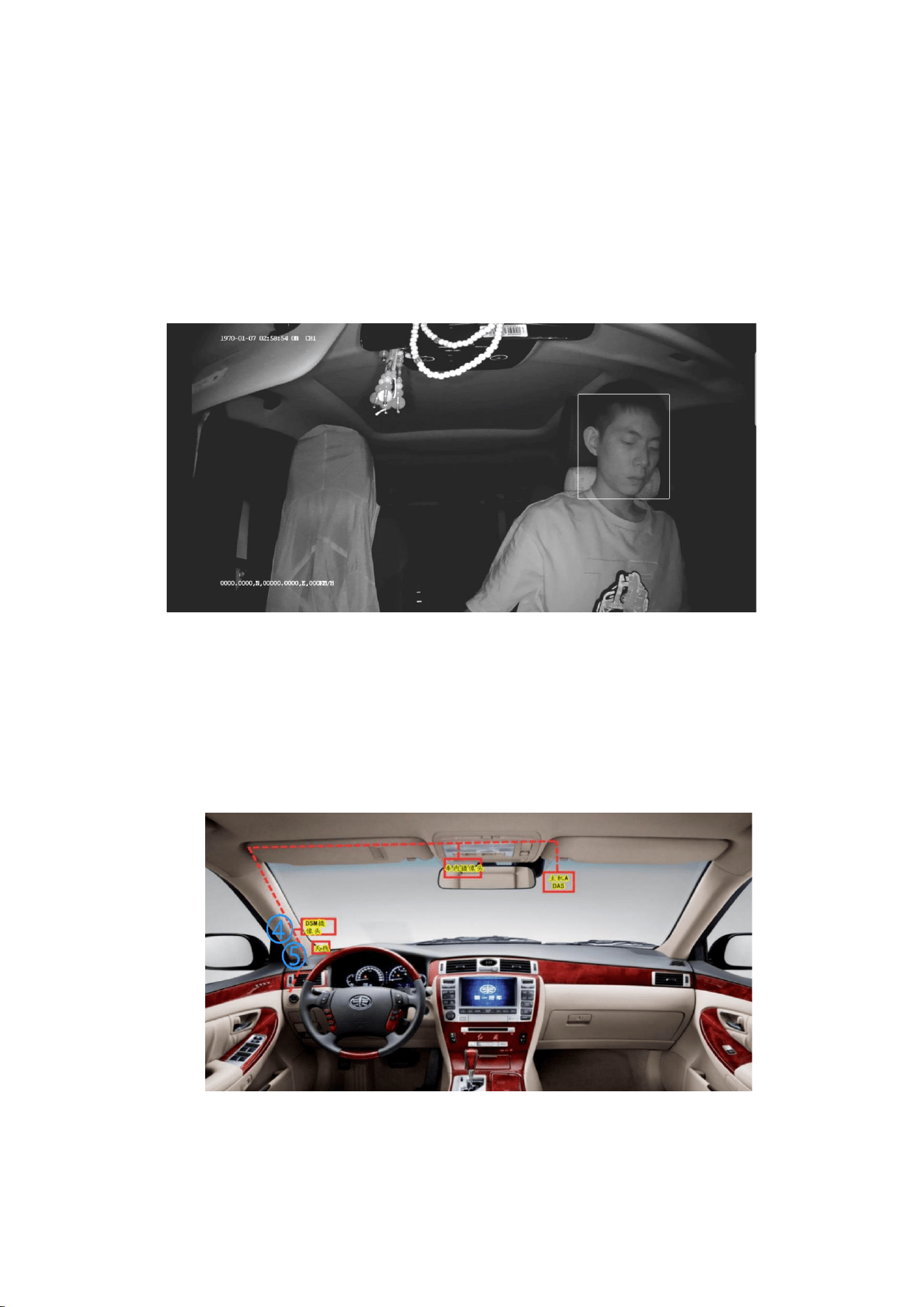
Refer to the figure above for the DMS camera installation position. If the main
unit has built-in front and rear dual cameras, positions ①② are recommended, with
the driver as centered as possible so the face is clearly visible, the head in the upper
area, and the entire head kept complete, as shown below;
If the main unit only has a front camera, the external DMS camera is
recommended at position ④ on the left side of the steering wheel, with the driver's
face centered in the image, as shown below. Note: Position ⑤ is the GPS antenna
location.
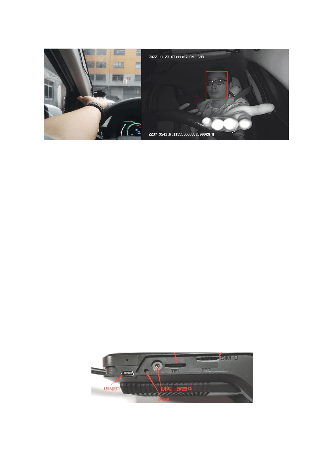
After powering on the main unit, use the APP to view the image. The DSM will
calibrate automatically; click 'Start Calibration', look straight ahead, and it will
automatically succeed and prompt by voice in about 3 seconds. Manual calibration is
also available.
7. Emergency Alarm Button Installation
The alarm button serves as an emergency alarm; install it in as concealed a
location as possible.
8. Reset Button
The device reset button restores the device's Wi-Fi to the default AP mode (Wi-Fi
name is the device number, password: 88888888), resets the device number to
empty, and restores the server network protocol to the CMSV6 protocol. The
device reset button is located next to the TF card, as shown in the figure below.
9. Device Upgrade
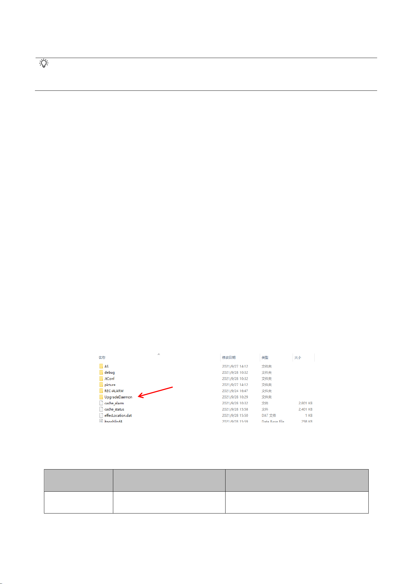
Upgrade files must be obtained by the user from the vendor.
Do not cut power during the upgrade process and do not perform any operation on the device;
otherwise the recorder upgrade will fail. Please operate with caution!
Method 1: TF Card Upgrade
① First store the firmware upgrade program into the TF card; (Note: Have the
device format the TF card first, then save the upgrade program.)
② Enter the system menu 'System Information' to view the application and MCU
version numbers; record or photograph them. The upgrade version number must
differ from the current version number;
③ Insert the TF card containing the upgrade file into the device card slot;
④ After inserting the TF card, the device will upgrade automatically. During the
upgrade, the device will restart; it will restart as many times as there are types of
upgrade files, so please wait patiently. The recorder automatically restarts and
emits a startup tone to indicate the upgrade is complete, as shown in the figure
below.
Troubleshooting
Symptom
Cause
Solution
Cannot Power On
Incorrect Power Wiring
Wire as required and ensure the input

voltage is within 8-36V
Power Cable Fuse Blown
Replace with a New Fuse
Connection
Failed
Center
Incorrect Parameter Settings
(Server Not Connected)
Reconfigure According to the Manual
SIM Card Out of Credit
(Dialing or Registration Failed)
Check and Then Top Up / Renew
Incorrect APN Parameters
(Dialing or Registration Failed)
Verify Parameters with the Carrier and
Reconfigure
Check Whether the SIM Card
Has Good Contact (No SIM
Card)
Reinstall the SIM Card
Disk Not Locked (Power Off)
Lock the Hard Disk Lock; a disk status
prompt appears in the upper right
corner
No Recording
Disk Not Formatted
Format the Disk Locally or Remotely
Disk Damaged
Replace the Disk
Disk Lock Not Engaged
Engage the Hard Disk Lock; the LCD
panel will show it
Cannot Locate
Vehicle Is in an Underground
Parking Lot or Tunnel
Drive Away from That Area
Stuck in 'Locating' Status
Tighten the Positioning Antenna and

Place It as Required
Antenna Short Circuit (Shown
on LCD Screen)
Replace the Positioning Antenna
No Image
Display
Incorrect Interface Definition
Verify That the Interface Definitions
Match
Incorrect Mode Setting
Set the Camera Mode in 'Basic
Settings'
Camera Damaged
Replace with a New Camera
Upgrade Failed
Software Versions Are
Identical
Use a Different Software Version
Software Model Mismatch
Use Software of the Matching Model
Improper Card
Insertion/Removal Causing
File Loss
Re-store the Software and Follow
Proper Procedures
Delayed Voice
Announcement
Delayed Announcement upon
Fatigue Driving or Other
Alarms
Insert the SIM Card and Connect the
4G Antenna
Definition of AI
sensitivity
The factory default values for
ADAS and DMS are 2.
The smaller the value, the higher the
sensitivity.
AI alarm video
attachments not
AI alarms are divided into
level one and level two. Level
The speed threshold for level one is
30-60 KM/H, and for level two it is

uploaded to the
platform
one alarms do not upload
attachments, while level two
alarms do.
above 60 KM/H. The thresholds can be
adjusted in the software or on the web.
AI calibration
offset
In the window, multiple
people, and the target person
is not automatically
recognized.
It is possible to manually drag the red
points on the calibration box for
calibration, and select the face within
the fixed position of the box.
Cannot Connect
to the Platform
Platform Device ID and Unit
Device ID Do Not Match
Enter the Correct Device ID
Incorrect Server IP or Port
Enter the Correct IP and Port
Computer or Device Not
Connected to the Network
Connect the Computer to the Network
or Connect the Device via Network
Cable
Remote Upgrade
Unsuccessful
The account, password, and
port set in Center Settings ->
Extended Settings -> FTP do
not match the FTP server
settings
Enter the Same Account, Password,
and Port
Upgrade File Not Placed in
the Root Directory
Place the Upgrade File in the Root
Directory
Upgrade File Has No Prefix
MCU prefix: 06_5656_5656_7878_

Application prefix:
01_5656_5656_7788_
Incorrect URL Format
For example, the correct application
URL format:
ftp@192.168.1.12:21/01_5656_5656_77
88_HJAV300JT-V19062701-V18070301
-V18112801-T19071605.3358.sw,
where 192.168.1.12 is the computer's
local IP and 21 is the port number,

FCC Warnning:
This equipment has been tested and found to comply with the limits for a Class B digital device,
pursuant to part 15 of the FCC Rules. These limits are designed to provide
reasonable
protection againstharmful interference in a residential installation. This equipment generates,
uses and can radiateradio
frequency
energy
and,
if
not
installed
and
used
in
accordance
with
the
instructions,
maycause
harmful
interference
to
radio
communications.
However,
there
is
no
guarantee
thatinterference
will
not
occur
in
a
particular
installation.
If
this
equipment
does
cause
harmfulinterference to radio or television reception, which can be
determined by turning the equipmentoff
and
on,
the
user
is
encouraged
to
try
to
correct
the
interference
by
one
or
more
of
thefollowing measures:
•
Reorient or relocate the receiving antenna.
•
Increase the separation between the equipment and receiver.
•
Connect the equipment into an outlet on a circuit different from that to which the receiver is
connected.
• Consult the dealer or an experienced radio/TV technician for help.
Caution:
Any
changes
or
modifications
to
this
device
not
explicitly
approved
by
manufacturer
could void your authority to operate this equipment.
This
device
complies
with
part
15
of
the
FCC
Rules.
Operation
is
subject
to
the
following
two
conditions:
(1)This
device
may
not
cause
harmful
interference,
and
(2)
this
device
must
accept
any
interference received, including interference that may cause undesired operation.
This
equipment
complies
with
FCC
radiation
exposure
limits
set
forth
for
an
uncontrolled
environment.
This
equipment
should
be
installed
and
operated
with
minimum
distance
20cm
between the radiator and your body.