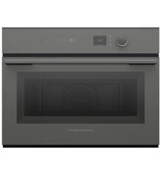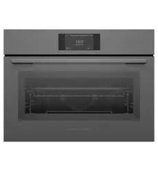

COMBI-MICROWAVE OVEN
INSTALLATION GUIDE
Components required 3
Accessing your product specifications 4
Prior to installation 7
Unpack product 8
Remove shelves 9
Connect power 10
Position in cavity 11
Align to surroundings 12
secure to cavity 13
Refit shelves 14
Checklist 15
NZ AU UK IE SG

MINIMAL
OM76NMUB3, OM76NMUG3, OM76NMUNB3, OM76NMUNG3,
OM60NMUNB5, OM60NMUNG5, OM60NMTB5, OM60NMTG5,
OM60NMUB5, OM60NMUG5
CONTEMPORARY
OM76NCUDX3, OM60NCUDX5, OM60NCTDX5
PROFESSIONAL
OM76NPUX3

3
COMPONENTS REQUIRED
TOOLS
Not supplied
F Powered driver
F Cross-head screwdriver
PARTS
Supplied
F Screw SD #7X13 PAN PH ZP (2)
F Cabinetry trim (some models only)
All imagery shown in this guide is representative. Your product may differ.
4
ACCESSING YOUR PRODUCT SPECIFICATIONS
Ventilation
required
For full product, cabinetry and service specifications, refer
to the Planning Guide. To access the Planning Guide, scan
the QR code or visit fisherpaykel.com/specify. Search by
appliance type, product name or model code.
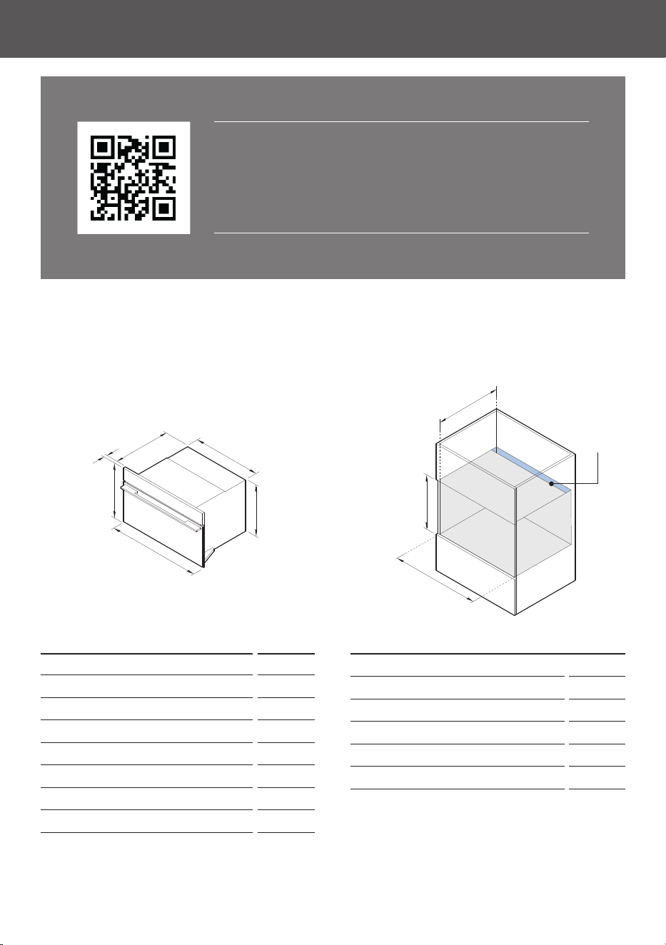
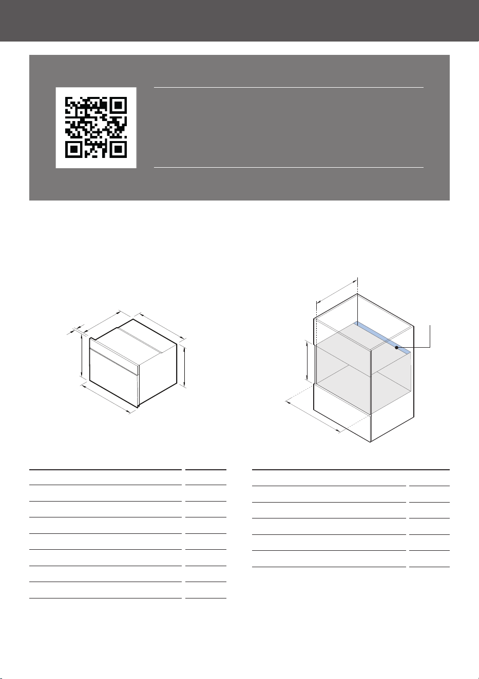
OM76N MINIMAL AND CONTEMPORARY MODELS
OM76NMUB3, OM76NMUG3, OM76NMUNB3, OM76NMUNG3, OM76NCUDX3
A
B
C
D
E
F
G
H
I
CAVITY DIMENSIONS mm
G Minimum inside height of cavity 440
H Minimum inside width of cavity 724
I Minimum inside depth of cavity* 550**
Recommended cabinet height 460
Recommended cabinet width 762
*Excluding control panel thickness.
**Requires ventilation at the rear of the cavity.
PRODUCT DIMENSIONS mm
A Overall height 458
B Overall width 758
C Chassis height 435
D Chassis width 720
E Chassis depth 545
F Control panel thickness 20
Depth with door fully open* 320
*Measured from front of control panel.
5
For full product, cabinetry and service specifications, refer
to the Planning Guide. To access the Planning Guide, scan
the QR code or visit fisherpaykel.com/specify. Search by
appliance type, product name or model code.
ACCESSING YOUR PRODUCT SPECIFICATIONS
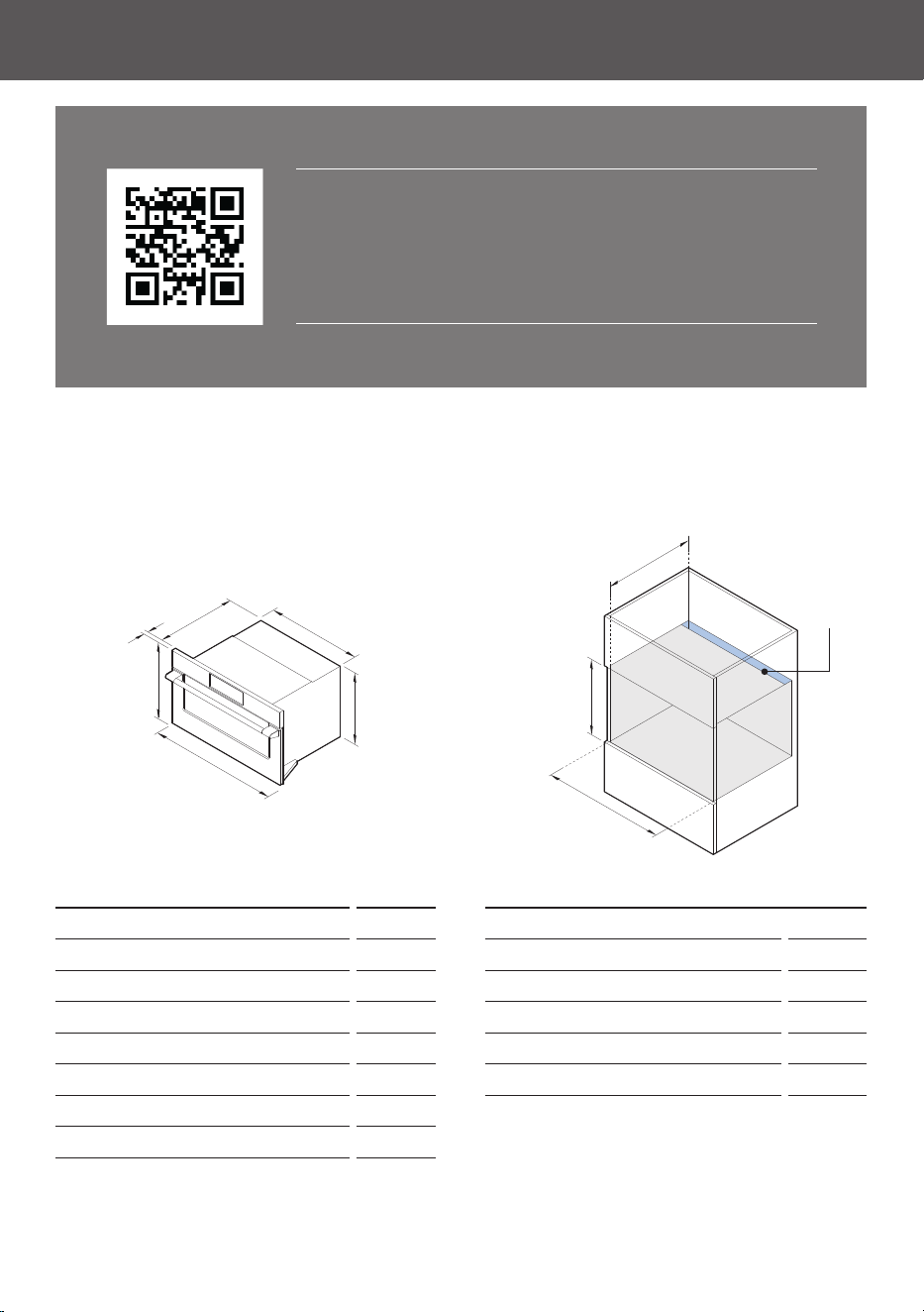
OM76N PROFESSIONAL MODELS
OM76NPUX3
A
B
C
D
E
F
G
H
I
Ventilation
required
CAVITY DIMENSIONS mm
G Minimum inside height of cavity 440
H Minimum inside width of cavity 724
I Minimum inside depth of cavity* 550**
Recommended cabinet height 460
Recommended cabinet width 762
*Excluding control panel thickness.
**Requires ventilation at the rear of the cavity.
PRODUCT DIMENSIONS mm
A Overall height 458
B Overall width 758
C Chassis height 435
D Chassis width 720
E Chassis depth 545
F Control panel thickness 24
Depth with door fully open* 320
*Measured from front of control panel.
6
For full product, cabinetry and service specifications, refer
to the Planning Guide. To access the Planning Guide, scan
the QR code or visit fisherpaykel.com/specify. Search by
appliance type, product name or model code.
ACCESSING YOUR PRODUCT SPECIFICATIONS
Ventilation
required
OM60N MINIMAL AND CONTEMPORARY MODELS
OM60NMUNB5, OM60NMUNG5, OM60NMTB5, OM60NMTG5, OM60NMUB5,
OM60NMUG5, OM60NCUDX5, OM60NCTDX5
A
B
C
D
E
F
G
H
I
CAVITY DIMENSIONS mm
G Minimum inside height of cavity 440
H Minimum inside width of cavity 560
I Minimum inside depth of cavity* 550**
Recommended cabinet height 460
Recommended cabinet width 600
*Excluding control panel thickness.
**Requires ventilation at the rear of the cavity.
PRODUCT DIMENSIONS mm
A Overall height 458
B Overall width 596
C Chassis height 435
D Chassis width 556
E Chassis depth 545
F Control panel thickness 20
Depth with door fully open* 324
*Measured from front of control panel.
7
PRIOR TO INSTALLATION
1. Refer to the Planning Guide
for cabinetry, cavity, panel and
service specifications.
For light cabinetry, ensure the
exposed cabinet edges have a
suitable finish.
2. Ensure the cabinet meets the
minimum cavity specifications
required.
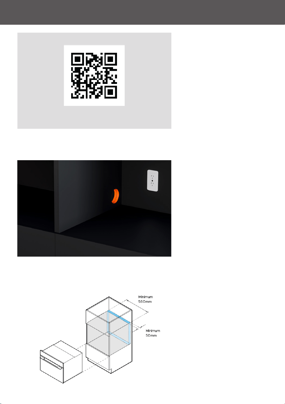
3. Ensure ventilation has been
set up correctly.
Refer to the planning guide for
details.
fisherpaykel.com/specify
8
UNPACK PRODUCT
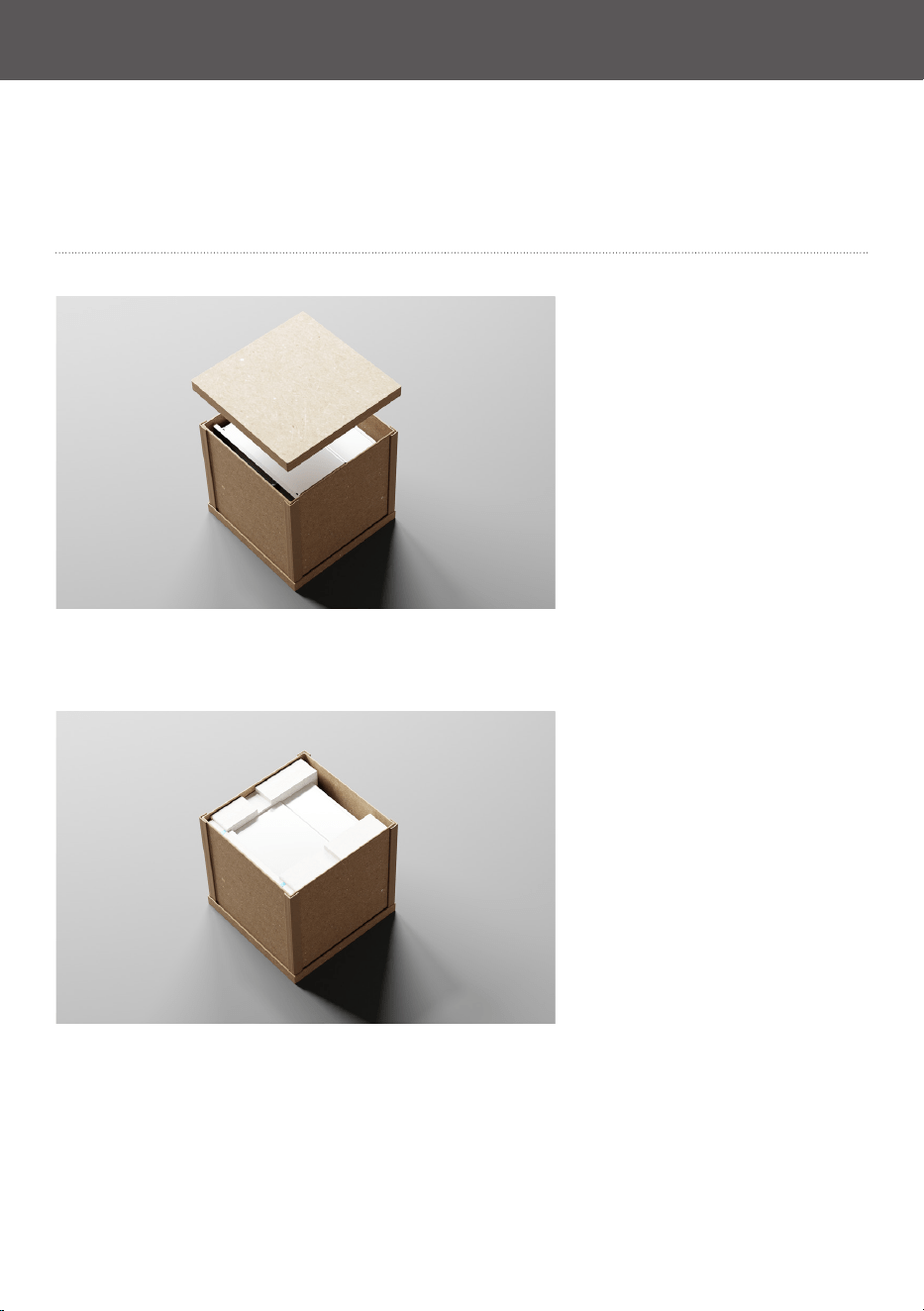
1. Cut all straps and remove the
carton top cap.
z
Do not lift or move the product using the door handle.
z
Keep all packing materials until the unit has been inspected.
z
Inspect the product to ensure there is no shipping damage. If any damage is detected
contact the dealer or retailer you bought the product from to report the damage.
z
Fisher & Paykel is not responsible for shipping damage.
2. Lift the carton sleeve and
remove any transit packaging.
Set aside any accessories.
Dispose of packaging
responsibly.
9
REMOVE SHELVES
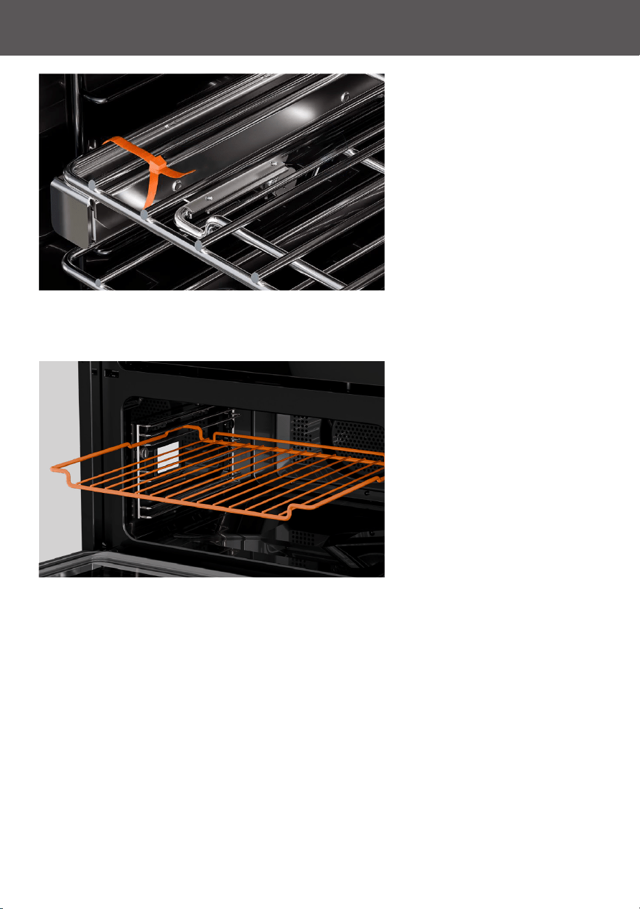
1. Open the door and remove all
cable ties and packaging holding
the oven shelves in place.
2. Grip the shelves at the front.
Lift upwards and pull out from
the microwave.
10
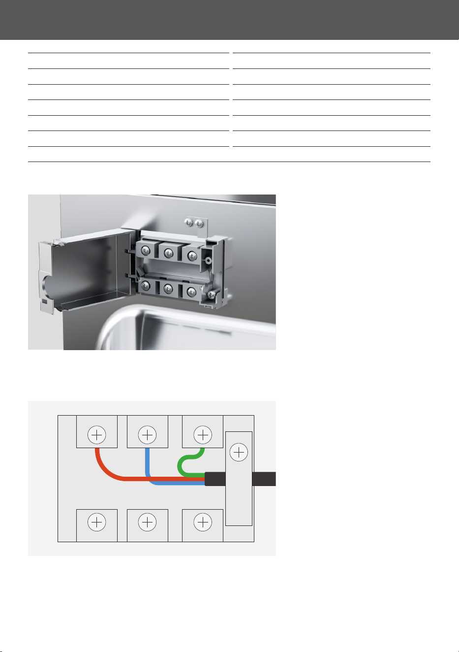
CONNECT POWER
1. Unclip and lift cover to access
terminal block.
2. Based on your terminal block
configuration, connect wires as
shown. Connector and ports may
not be present on all models.
Ensure oven is correctly earthed
and cable clamp is tightened
before closing the cover.
SPECIFICATIONS OM76 OM60 MODELS
RATED POWER (W) 3800
Hz 50
VOLTAGE ( V ) 220 – 240V
MICROWAVE RATED INPUT (W) 2000
MICROWAVE RATED OUTPUT (W) 900
MICROWAVE FREQUENCY (MHz) 2450
11
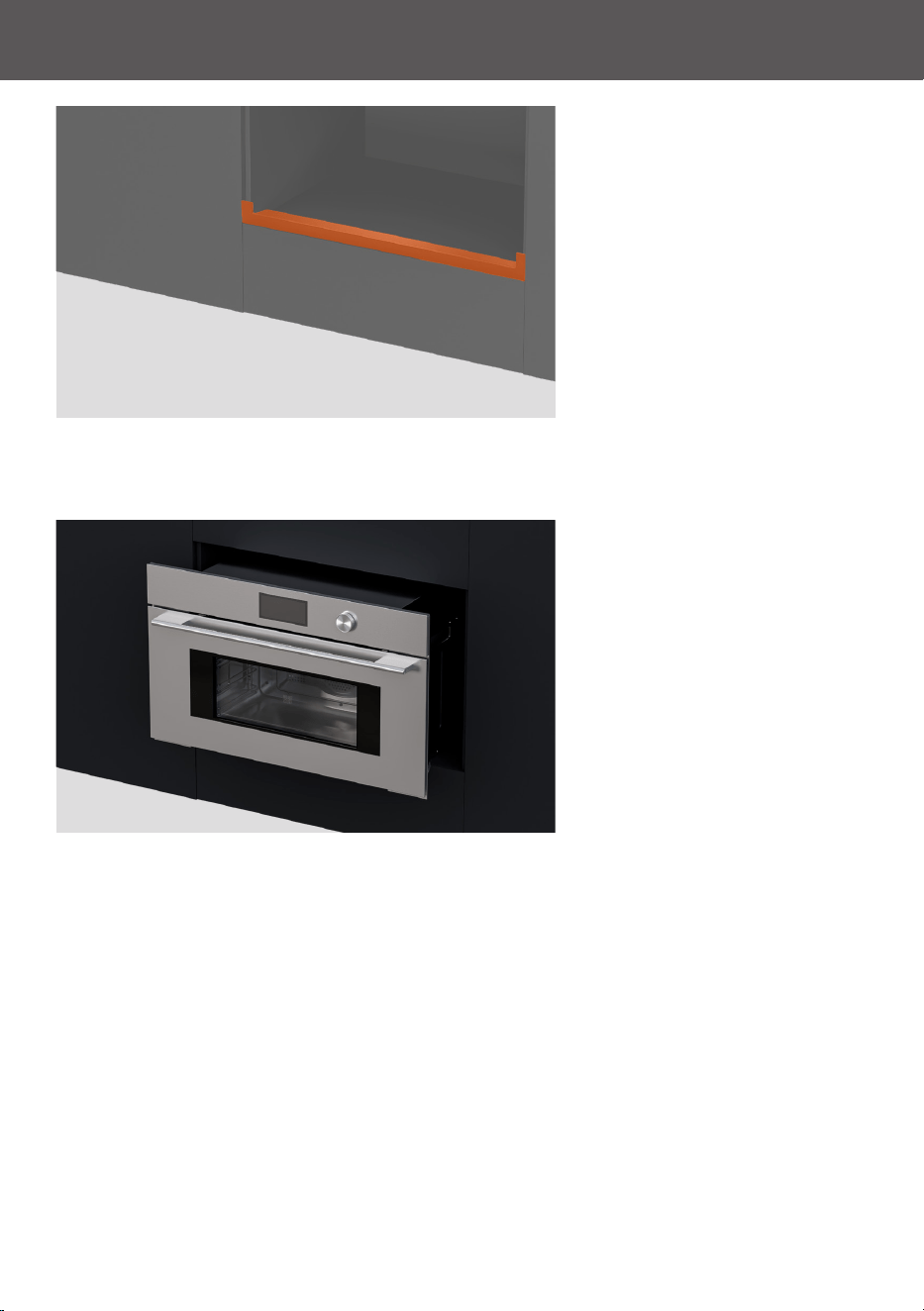
POSITION IN CAVITY
2. Lift product into cavity.
*To purchase cabinetry trim as an optional accessory, visit fisherpaykel.com
1. For light cabinetry, the
supplied trim can improve the
overall finish. To install, peel off
the adhesive backing and press
the trim firmly into place on the
cavity*.
12
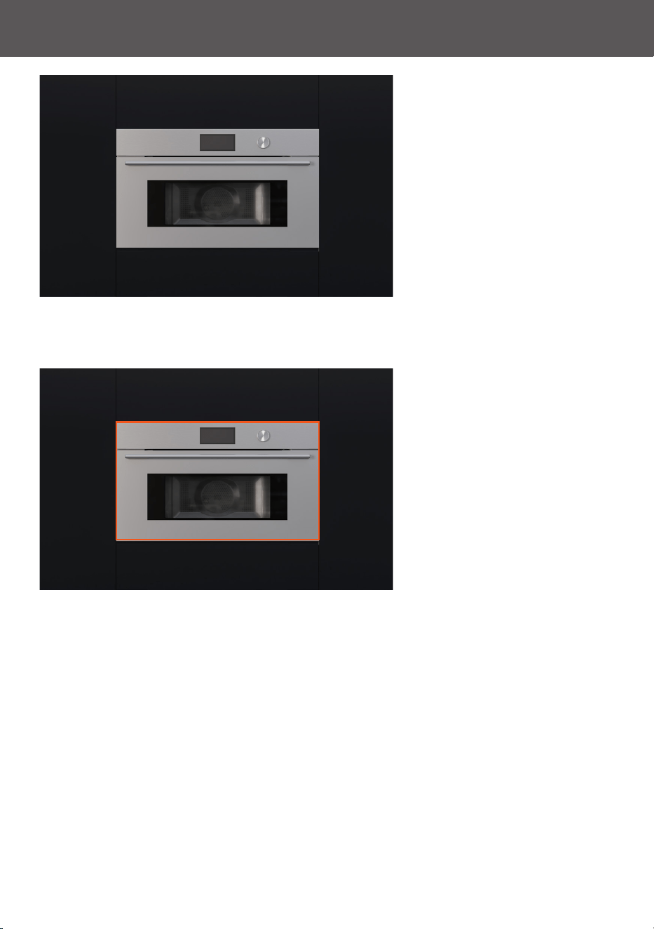
ALIGN TO SURROUNDINGS
1. Align microwave with
surrounding cabinetry and
appliances.
2. Ensure the vertical gaps
are even before making any
horizontal adjustments.
13
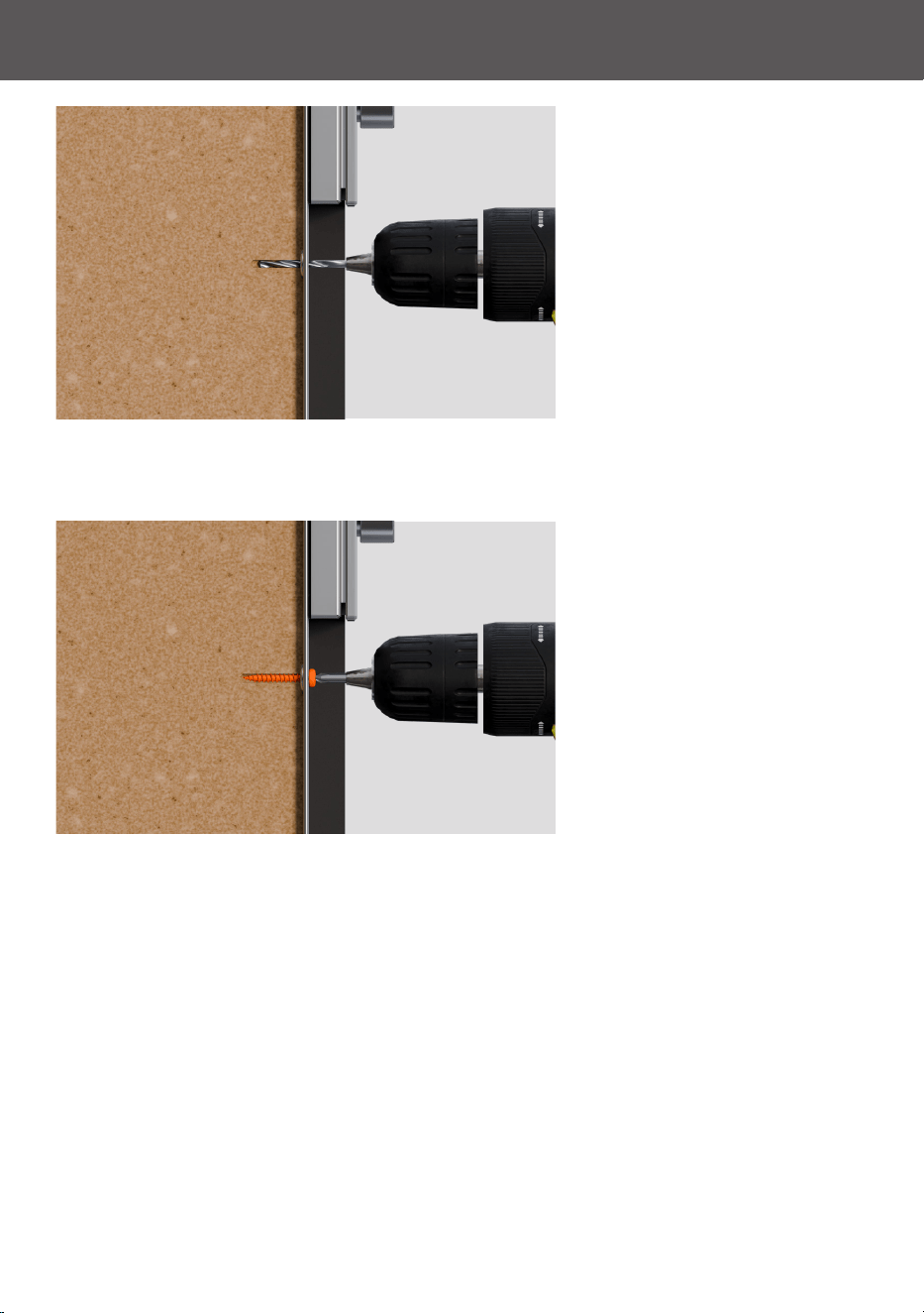
SECURE TO CAVITY
1. Using the product as a guide,
pre-drill 2 x 3mm pilot holes.
2. Secure oven to cavity using
the 2 x screws provided.
14
REFIT SHELVES
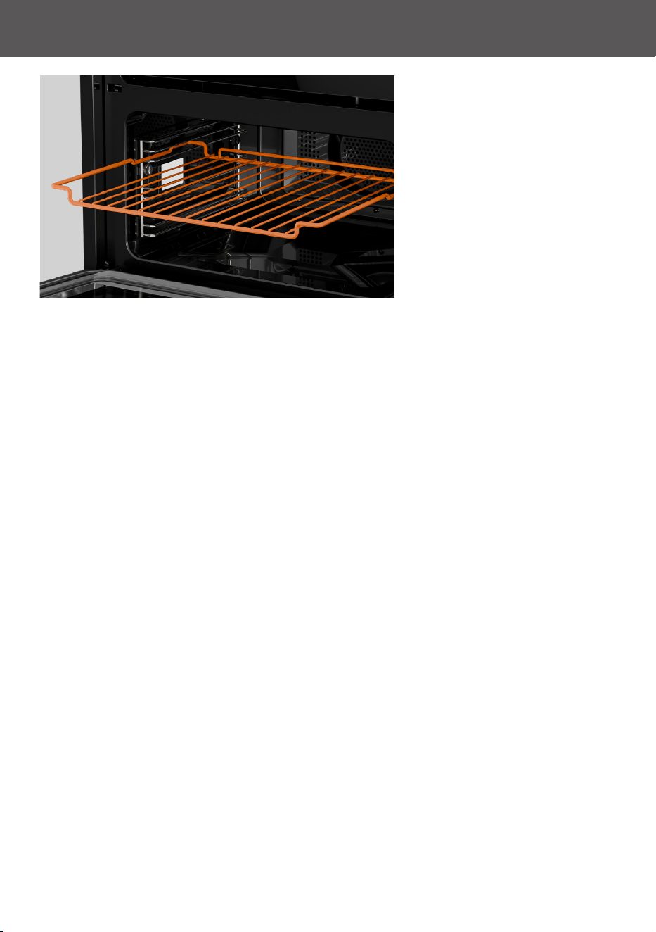
1. Reposition shelves in the oven
at the desired level.
Ensure shelves are level and
correctly positioned with the
guard rail at the back.

15
Complete and keep for safe reference:
Model
Serial no.
Purchase date
Purchaser
Dealer address
Installer’s name
Installer’s signature
Installation company
Installation date
Installation checks
F All clearances are correct.
F The product is level and securely fitted in the cabinetry.
F Ensure all ventilation has been set up correctly.
F All internal packaging is removed.
F The isolating switch can be easily reached.
Test operation
F Turn product on at the power supply.
F Follow the on-screen guidance to connect the product to Wi-Fi and set the clock.
CHECKLIST

433429B 09.26
© Fisher & Paykel Appliances 2026. All rights reserved.
The models shown in this guide may not be available in all markets
and are subject to change at any time.
The product specifications in this guide apply to the specific products and models
described at the date of issue. Under our policy of continuous product improvement, these
specifications may change at any time.
For current details about model and specification availability in your country,
please go to our website or contact your local Fisher & Paykel dealer.
FISHERPAYKEL.COM