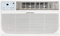

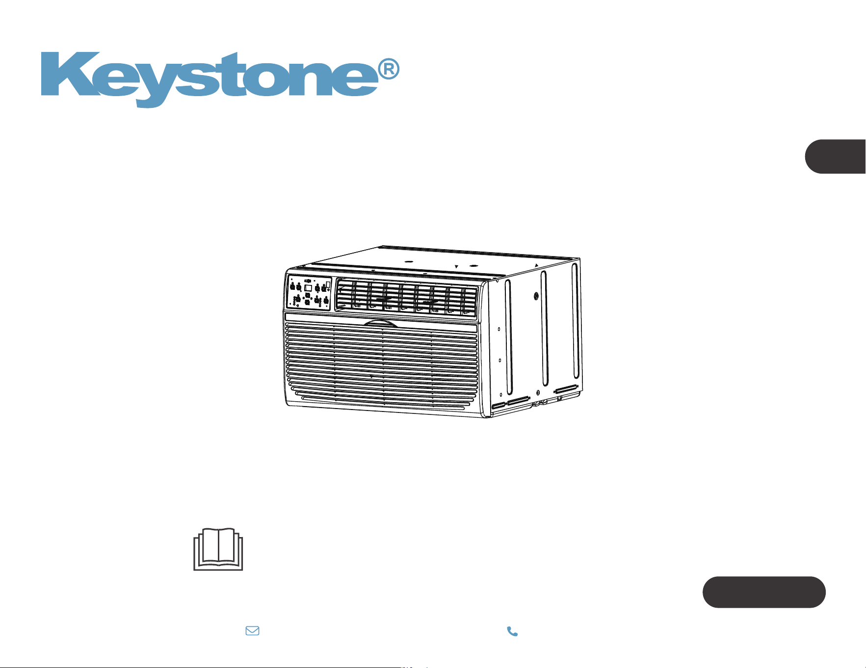
WALL TYPE ROOM AIR CONDITIONER
Owner’s Manual
IMPORTANT NOTE:
Before using your air conditioner, please read
this manual carefully and keep it for future reference.
TTW Series
EN
Model: KSTAT08-1E
KSTAT10-1E
KSTAT10-2E
KSTAT12-1E
KSTAT12-2E
KSTAT14-2D
KSTAT08-1HD
KSTAT10-2HD
KSTAT12-2HD
KSTAT14-2HD
800-849-1112
|


Troubleshooting
01
06
28
22
23
CONTENTS
Operation instructions
Installation instructions
Safety precautions
What is in the box
07
1 0
Before you get start
Install your product.
Get to know your AC.
Get to know the features.
Cleaning & Maintenance
27

01
Inside you will find many helpful hints on how to use and maintain
your air conditioner properly. Just a little preventive care on your
part can save you a great deal of time and money over the life of
your air conditioner. You'll find many answers to common problems
in the chart of troubleshooting tips. If you review our chart of
Troubleshooting Tips first, you may not need to call for service at all.
To prevent injury to the user or other people and property
damage, the following instructions must be followed.
Incorrect operation due to ignoring of instructions may
cause harm or damage. The seriousness is classified by the
following indications.
Safety Precautions
WARNING
The signal word indicates a hazard with a medium level of risk which, if not avoided, may result in death or serious injury.
ALWAYS DO THIS
This signal means that the operation can be performed.
CAUTION
The signal word indicates a hazard with a low degree of risk which, if not avoided, may result in minor or moderate injury.
Explanation of Symbols
NEVER DO THIS
This signal indicates the prompt operation is prohibited., if not avoided, may result in Product damaged or injury.
Must read the warning message.
02
Plug in power plug properly. Otherwise, it may cause electric shock
or fire due to excess heat generation. Do not operate or stop the unit
by inserting or pulling out the power plug.It may cause electric shock
or fire due to heat generation. Do not damage or use an unspecified
power cord.It may cause electric shock or fire. If the power cord is
damaged, it must be replaced by the manufacturer or an authorised
service centre or a similarly qualified person in order to avoid a hazard.
Always install circuit breaker and a dedicated power circuit. Incorrect
installation may cause fire and electric shock. Do not operate with wet
hands or in damp environment. It may cause electric shock . Do not
direct airflow at room occupants only. This could damage your health.
electric shock. Do not allow water to run into electric parts.It may
cause failure of machine of electric shock. Do not modify power cord
length or share the outlet with other appliances. It may cause electric
shock or fire due to heat generation.
WARNING
Unplug the unit if strange sounds, smell, or smoke
comes from it. It may cause fire and electric shock.
Do not use the socket if it is loose or damaged. It
may cause fire and electric shock. Do not open the
unit during operation. It may cause electric shock.
Keep firearms away. It may cause fire. Do not use
the power cord close to heating appliances.It may
cause fire and electric shock. Do not use the power
cord near flammable gas or combustibles, such as
gasoline, benzene, thinner, etc. It may cause an
explosion or fire.
Ventilate room before operating air conditioner if
there is a gas leakage from another appliance. It may
cause explosion, fire and, burns. Do not disassemble
or modify unit. It may cause failure and electric shock.
When the air filter is to be removed, do not touch the metal parts of
the unit. It may cause an injury.
Ventilate the room well when used together with a stove, etc. An
oxygen shortage may occur.
Do not use strong detergent such as wax or thinner but use a soft cloth.
Appearance may be deteriorated due to change of product color or
scratching of its surface. Do not clean the air conditioner with water.
Water may enter the unit and degrade the insulation. It may cause an
electric shock. Do not use for special purposes. Do not use this air
conditioner to preserve precision devices, food, pets, plants, and art
objects.lt may cause deterioration of quality, etc.
CAUTION
Stop operation and close the window in storm or
hurricane. Operation with windows opened may cause
wetting of indoor and soaking of household furniture.
When the unit is to be cleaned, turn o the unit and
unplug the power cord.
Do not clean unit when power is on as it may cause fire
and electric shock, it may cause an injury.
Always insert the filters securely. It can be caused
failure if operated without filters. Please clean filter
once every two weeks.
03
Cooling
operation
Outdoor temp:
Indoor temp:
Heating
operation
Outdoor temp:
O
O
23-76 F/ C-5-24
Indoor temp:
O
32-80 F/
O
0-27 C
O O O O
64-109 F/18-43 C (64-125 F/18-52 C
for special tropical models)
O
62-90 F/
O
17-32 C
Do not place obstacles around air-inlets or inside of air-outlet.
It may cause failure of appliance or accident. Do not place
heavy object on the power cord and ensure that the cord is
not compressed. There is danger of fire or electric shock. Don’t
drink water drained from air conditioner. It contains
contaminants and could make you sick.
Use caution when unpacking and installing. Sharp edges could
cause injury.
power-plug out and contact a qualified service technician.
This appliance is not intended for use by persons(including
children) with reduced physical, sensory or mental capabilities
or lack of experience and knowledge,
CAUTION
Hold the plug by the head of the power plug when taking
main power switch when not using the unit for a long time.
It may cause failure of product or fire.
Installation must be performed in accordance with the
requirement of NEC and CEC by authorized personnel only.
Do not operate your air conditioner in a wet room such as a
bathroom or laundry room.
The appliance with electric heater shall have at least 1 meter
space to the combustible materials.
Contact the authorised service technician for repair or
maintenance of this unit.
Contact the authorised installer for installation of this unit.
unless they have been given supervision or instruction
concerning use of the appliance by a person responsible for
their safety.
Children should be supervised to ensure that they do not play
with the appliance.
If the supply cord is damaged, it mus
t be replaced by the
manufacturer, its service agent or similarly qualified persons
in order to avoid a hazard.
The appliance shall be installed in accordance with national
wiring regulations.
NOTE
Note:Performance may be
reduced outside of these
operating temperatures.
This air conditioner is designed to be operated under the following conditions:
04
NOTE
Always make sure the RESET button is pushed in for
correct operation.
The power supply cord must be replaced if it fails to
reset when either the TEST button is pushed or if it
cannot be reset. A new one can be obtained from the
product manufacturer.
The power supply cord with this air conditioner
contains a current detection device designed to reduce
the risk of fire.
In the event that the power cord is damaged, it cannot
be repaired – it must be replaced with a cord from the
product manufacturer.
Operation of Current Device
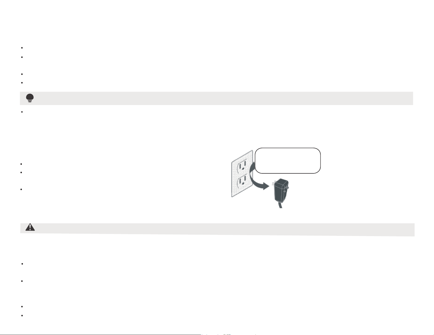
The power supply cord contains a current device that senses damage to the power cord. To test your power supply cord do
the following:
Plug in the Air Conditioner.
The power supply cord will have TWO buttons on the plug head. Press the TEST button, you will notice a click as the
RESET button pops out.
Press the RESET button again, you will notice a click as the button engages.
The power supply cord is now supplying electricity to the unit. (On some products this is also indicated by a light on the plug head).
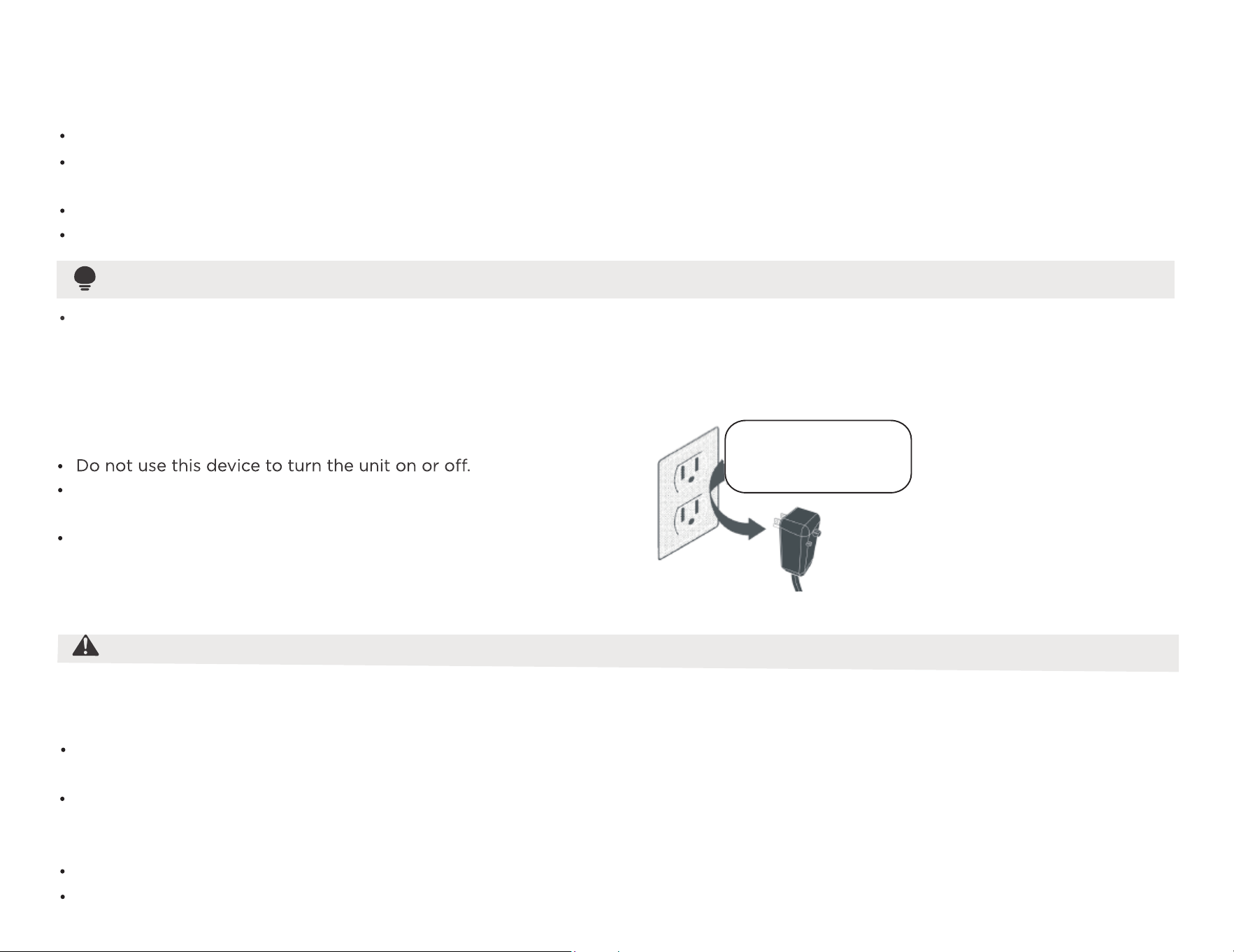
Do not, under any
circumstances, cut,
remove, or bypass
the grounding prongs.
Grounding type wall receptacle
Power supply cord with
3-prong grounding plug
and current detection
device.
WARNING
The complete electical rating of your new room air conditioner is stated on the serial plate. Refer to the rating when checking the
electrical requirements.
Be sure the air conditioner is properly grounded. To minimize shock and fire hazards, proper grounding is mandatory. The power cord
is equipped with a three-prong grounding plug for protection against shock hazards.
Your air conditioner must be used in a properly grounded wall receptacle. If the wall receptacle you intend to use is not adequately
grounded or protected by a time delay fuse or circuit breaker, have a qualified electrician install the proper receptacle. Ensure the
receptacle is accessible after the unit installation.
Do not run a
ir conditioner without side protective cover in place.This could result in mechanical damage within the air conditioner.
Do not use an extension cord or an adapter plug.
Electrical Information
05
Do not store or use gasoline or other flammable vapors and
liquids in the vicinity of this or any other appliance.
To reduce the risk of fire, electrical shock, or injury to persons
when using your air conditioner, follow basic precautions,
including the following:
Be sure the electrical service is adequate for the model you
have chosen. This information can be found on the serial
plate, which is located on the side of the the cabinet and
behind the grille.
For Your Safety
Prevent Accidents
Be sure the air conditioner has been securely and correctly
installed according to the installation instructions in this
manual. Save this manual for possible future use in removing
or installing this unit. When handling the air conditioner, be
careful to avoid cuts from sharp metal fins on front and rear
coils.
WARNING
Avoid fire hazard or electric shock. Do not use an extension
cord or an adapter plug. Do not remove any prongs from
the power cord.
Electronic Work
WARNING:
BEFORE PERFORMING ANY ELECTRICAL OR WIRING WORK, TURN OFF THE MAIN POWER TO THE SYSTEM.
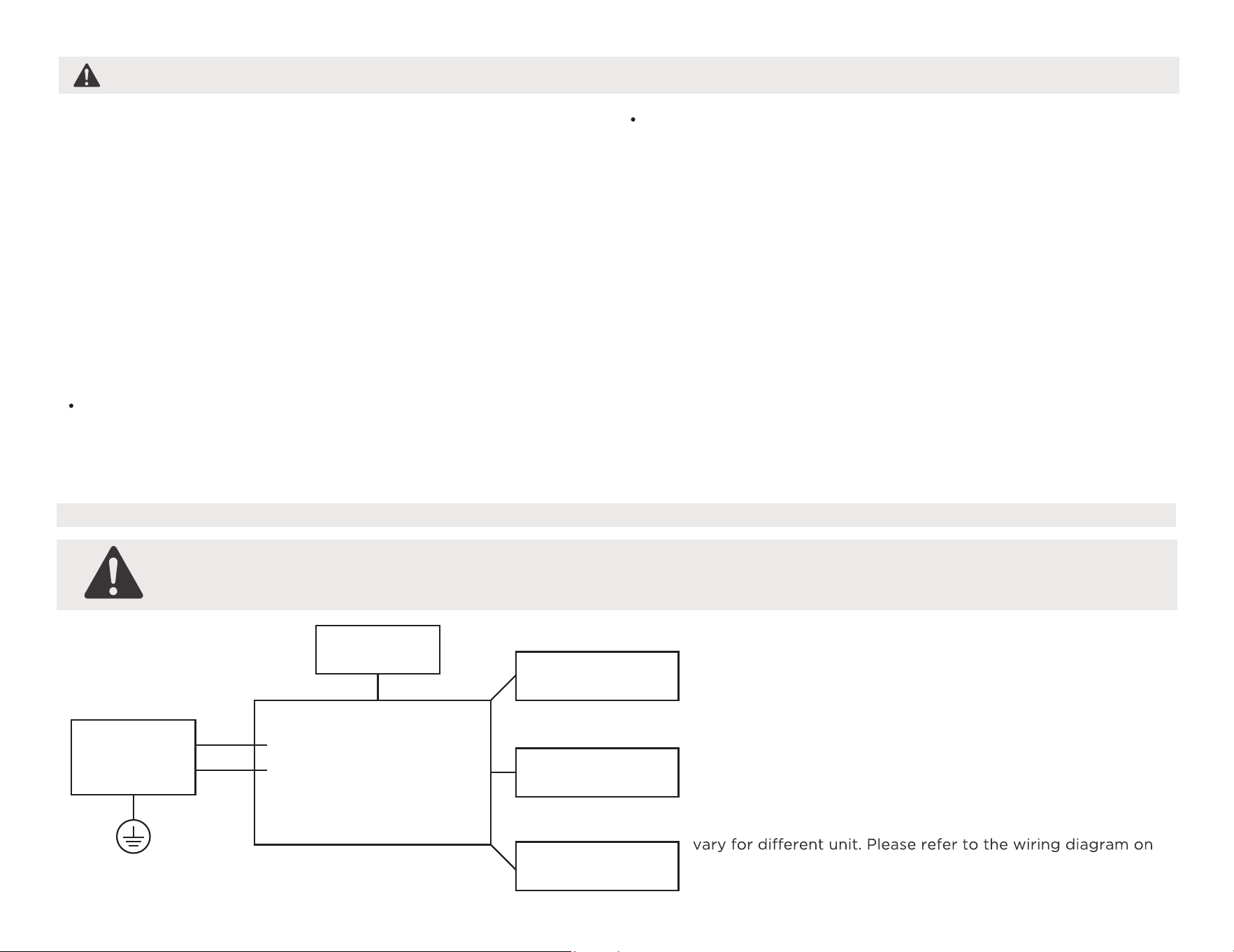
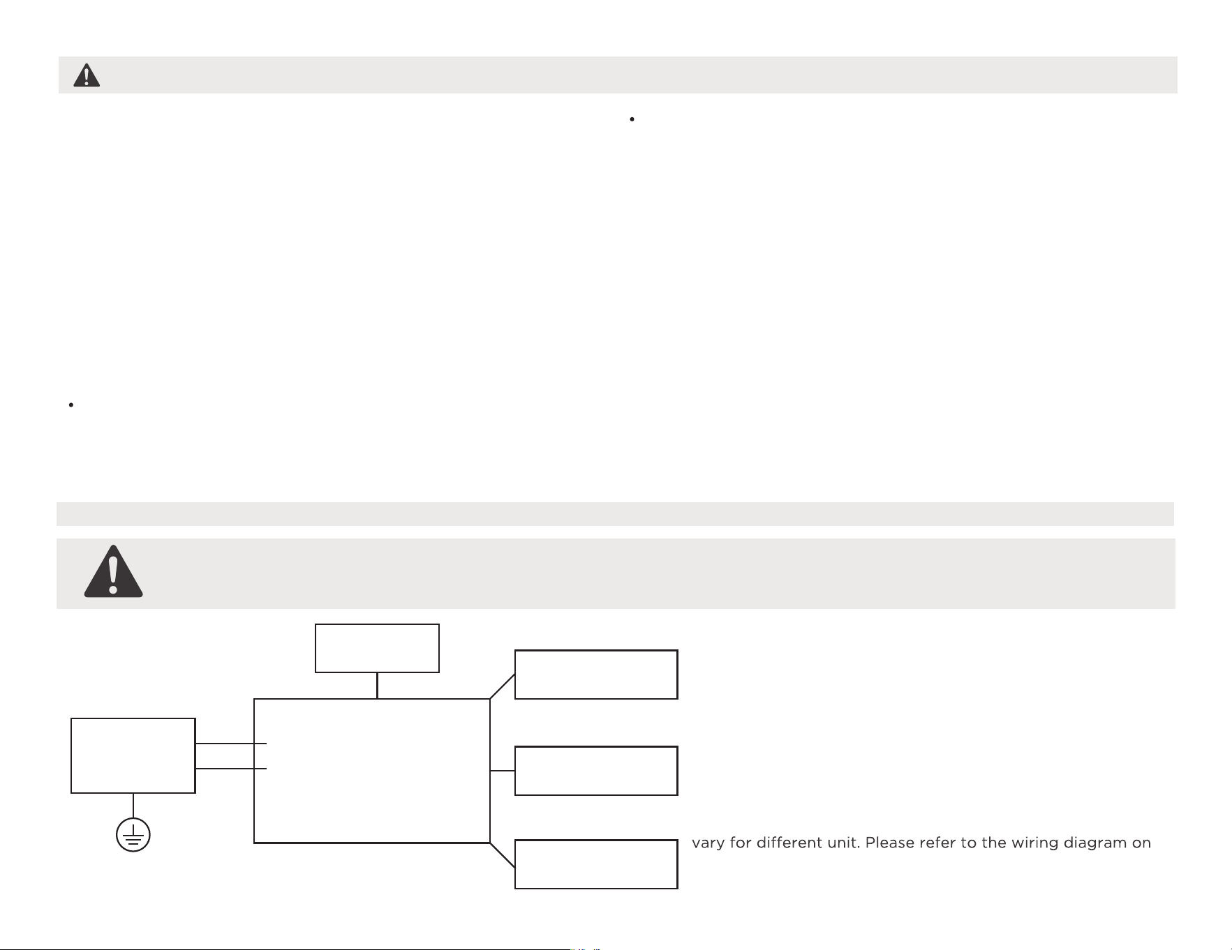
NOTE:
Please strictly follow the wiring label attached to the
machine for all wiring connections. The wiring diagram may
the machine you have purchased. The above wiring diagram
is a simplified version for preliminary illustration purposes only.
Main Control
Compressor
Fan Motor
Display
Power
Supply
L/AC L/L1/L-IN
N/AC N/L2/N-IN
Other
Electronic Type
What is in the Box.
CAUTION
Do not, under any circumstances, cut or remove the third
(ground) prong from the power cord.
Do not change the plug on the power cord of the air
conditioner.
Aluminum house wiring may present special problems- consult
a qualified electircian.
When handling unit, be careful to avoid cuts from sharp metal
edges and aluminum fins on front and rear coils.
Have two or more persons to move and install the unit.
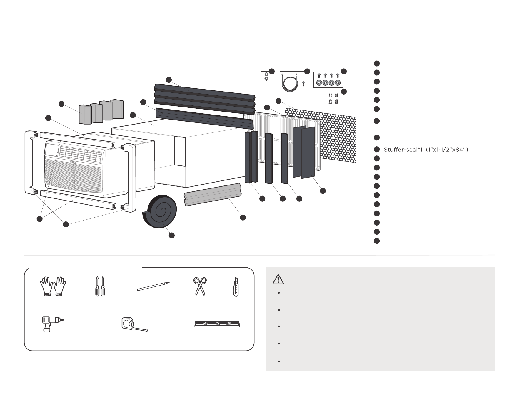
Package content
06
1
4
7
5
6
3
2
8
9
10 11 12
15
13
14
16
17
18
19
Seal*2 (1"x3/8"x14")
Seal*2 (1"x1-1/2"x14")
Tapered Spacer Block(Blue)*2
(7/8"x1-1/8"x17")
Centering/Support Blocks(Blue)*4
(4-1/2"x3-1/2"x1-1/2")
Seal*2 (1"x3/8"x25")
Seal*3 (1"x1-1/2"x25")
Plastic Divider*2 (1/8"x4-1/2"x14-1/2")
Seal*2 (1"x3/4"x14")
1
3
2
5
4
7
6
8
10
11
12
13
14
15
16
17
18
19
9
Air Conditioner Unit
Trim Frame (top & bottom legs)*2
Trim Frame (side legs)*2
Wall Sleeve (purchase separately)
Aluminum Grille
Plastic Grille (1/8"x4-1/2"x14-1/2")
Screw*4 and Screw Washer*4
Nuts(plastic)*4
Ground Wire and Grounding Screw
Toothed Washer for Grounding Screw
Level
Ruler or tape measure
Drill
*Not Included
PencilGloves Screwdriver Scissors&Knife
Prepare the following tools
07
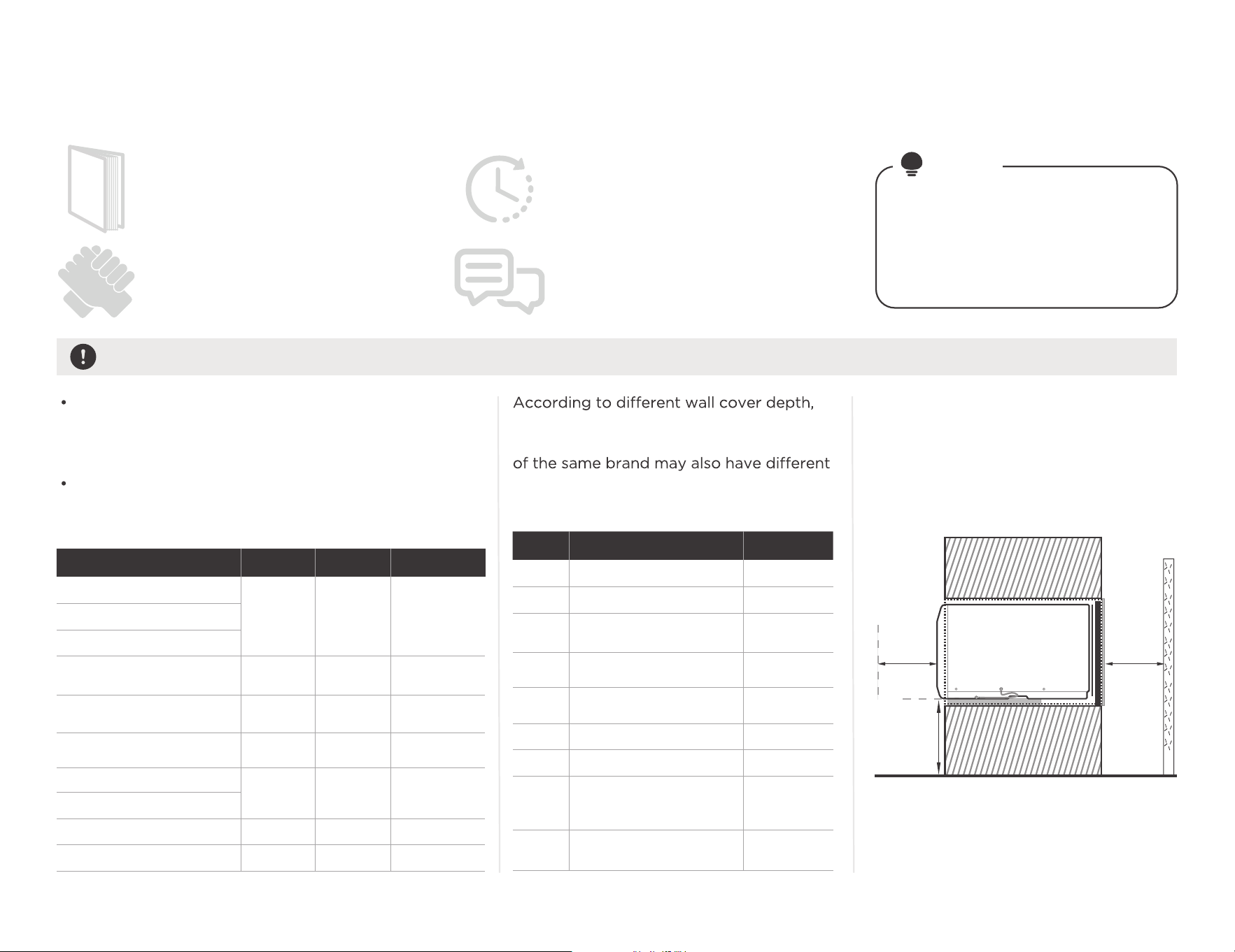
Before you get start.
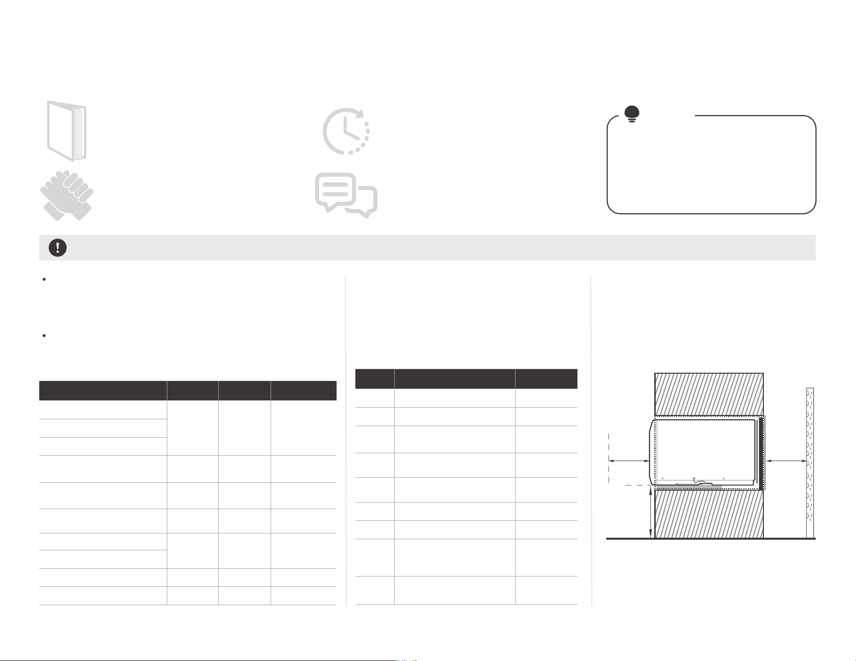
Confirm your installation location requirements and Wall Sleeve Dimensions.
The Air Conditioner dimensions are: 24" wide, 1 4" high,
and 18" deep (without front panel). Install Air
Conditioner according to these installation instructions
to achieve the best performance.
Confirm the size of the wall sleeve according to your
hole in the wall, identify the wall-sleeve brand for your
installation, from the chart below.
NOTE
Installing your AC should take about
60 minutes.
The installation must be carried out
in strict accordance with the instructions
in this manual.
Manual
We recommend doing this with a helper.
We’re here if you need us, please contact
your local distributor for assistance.
Save Carton and these Installation
Instructions for future reference.
The carton is the best way to
store unit during winter, or when
not in use.
Preparations before installation
25-1/2"
26"
25-7/8"
27"
25-3/4"
26-3/4"
27"
15-1/4"
15-5/8"
16-1/2"
16-3/4"
16-7/8"
15-3/4"
16-3/4"
16",17-1/2"
or 22"
15"
19-3/4"
16-3/4"
18-5/8"
17-1/8"
23"
16/17-1/2"
22"
17-1/8"
or 23"
16-3/4"
or 19-3/4"
18-5/8"
15"
16-3/4"
WidthBrand Height Depth
White-Westinghouse
Frigidaire
Friedrich
Carrier(52F Series)
Carrier(51S Series)
General Electric/
Hotpoint
Whirlpool
Sears/Kenmore
Fedders/Emerson
Emerson/Fedders
Brand DepthType
Emerson
#1
#2
#3
#4
#5
#6
#7
#8
#9
Fedders
Fedders/
Friedrich
White-Westinghouse/
Frigidaire/
Carrier(52F Series)
White-Westinghouse/
Frigidaire
General Electric/
Hotpoint
Sears/
Carrier(51S Series)
Whirlpool
Whirlpool
we have divided the installation into 9
categories. Please note that the wall cover
depths. Please install according to
the depth.
Over
51cm
(20")
Over
51cm
(20")
Over
12.2 to 16cm
(4-13/16"
to 6-5/16")
To make the appliance work better,
please do not place a barrier in the air
outlet, and select the installation location
of the product according to the
requirements in the following figure.
Side View
16-3/8"
16-3/8"

Complete the installation of Wall Sleeve.
Preparations before unit installation
08
CAUTION:
All wall sleeves used to mount the new Air Conditioner must be in sound structural
condition and have a rear grille that securely attaches to sleeve, or rear flange that
serves as a stop for the Air Conditioner.
When installation is complete, replacement unit MUST have a rearward slope as shown.
Do not use any screws other than those specified here.
Angle:3-4°
Rear
Level
Front
UNIT
Wall Sleeve
Install the wall sleeve and make grounding connection
Remove old Air Conditioner from wall sleeve and prepare wall
sleeve(if any). Clean interior (do not disturb seals).
Under the front of the wall cover, there are two 1/8" holes for
ground operation. Use the Ground Wire and Ground
Screw(No. 18), and Toothed Washerin(No. 19) the fitting bag for
ground installation.
Normal grounding operation
Unconventional grounding wire
operation (hole drilling required)
1/8"
hole
1"
3"Max
Wall sleeve must be securely fastened in wall before installing Air
Conditioner. Drive more nails or screws through sleeve, into wall,
if needed(Repair paint if needed).
If there is no ground wire installation hole, please drill a 1/8 clearance
hole for grounding screw through left side of wall sleeve, in a clear area
about 3" maximum back from front edge of sleeve, using grounding
screw and toothed washer. Pull loose end of ground wire out front of
sleeve, and temporarily bend it down and around lower edge of sleeve.
This ground wire will later be attached to frame of air conditioner once
it is installed.
You can choose the left side or
the right side for grounding.

09
We have a new design for the rear grille (two rear air intakes) to improve the performance of the product. Please be sure to use
the aluminum grille we provide for installation to achieve the best performance of the product.
Most decorative exterior grilles may be left in place as long as the proper interior air direction grille is installed.
NOTE
Installation of new grille provided with unit
Installation of Aluminum Grille.
Remove the existing grille.
Place the grille included with the new air
conditioner towards the rear of the sleeve.
Top View
Wall Sleeve
Rear
grille
Outdoor side
Indoor side
Mark through the hole positions.
Drill through the sleeves flanges with a 1/8"
drill bit.
Attached the new grille with self-threading
screws and washers.
Attached the new grille with self-threading
screws and washers.
(with Normal Wall Sleeve)
Confirmation of
installation position.
1
Install Aluminum Grille.
2
(with Unconventional Wall Sleeve)
Install Aluminum Grille.
3
Simple diagram
of the rear grille
With four
washers(No.17)
Rear
side
Please press the four washers into
the hole of the wall sleeve before
installing the aluminum grille and
tightening the screws.
Simple diagram
of the rear grille
Drill through the
sleeves flanges
with a 1/8"drill bit.
10
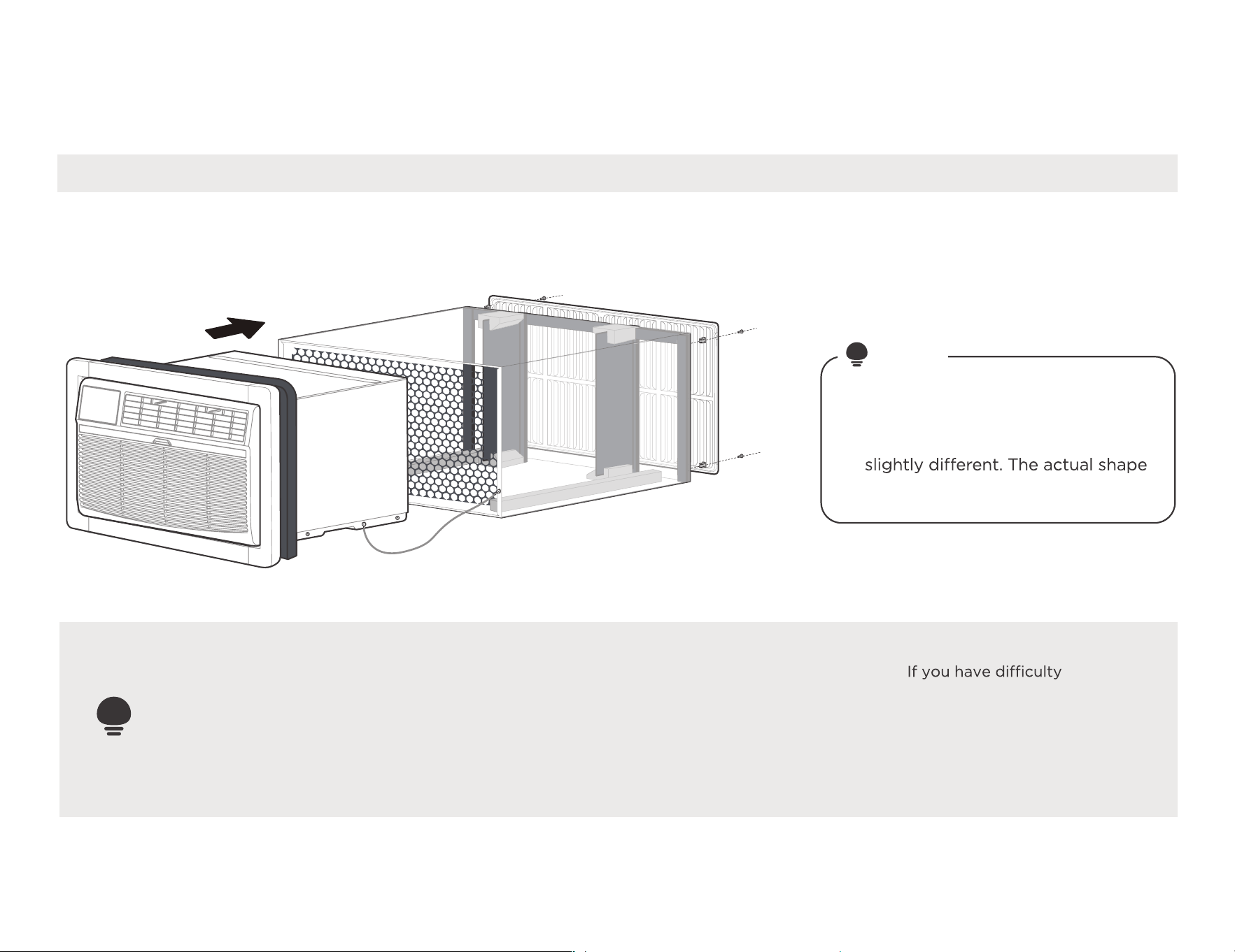
Install your product.
Installation overview
Illustrations in this manual are for
explanatory purposes. The actual
shape of your indoor unit may be
shall prevail.
NOTE
#9 White Westinghouse or Frigidaire for example
IMPORTANT
Save these instructions for local inspectors
use. Observe all governing codes and
ordianaces. Proper installation is the responsibility
of the installer. Product failure due to improper
installation is not covered under the Warranty.
Nine installation methods we will
provide, please choose one of the
corresponding installation method
(follow the instructions on page 7
to determine the type) to finish
the installation.
with mounting the grill
to the sleeve, follow the
instructions for direct
mounting on Page 20.
1 2
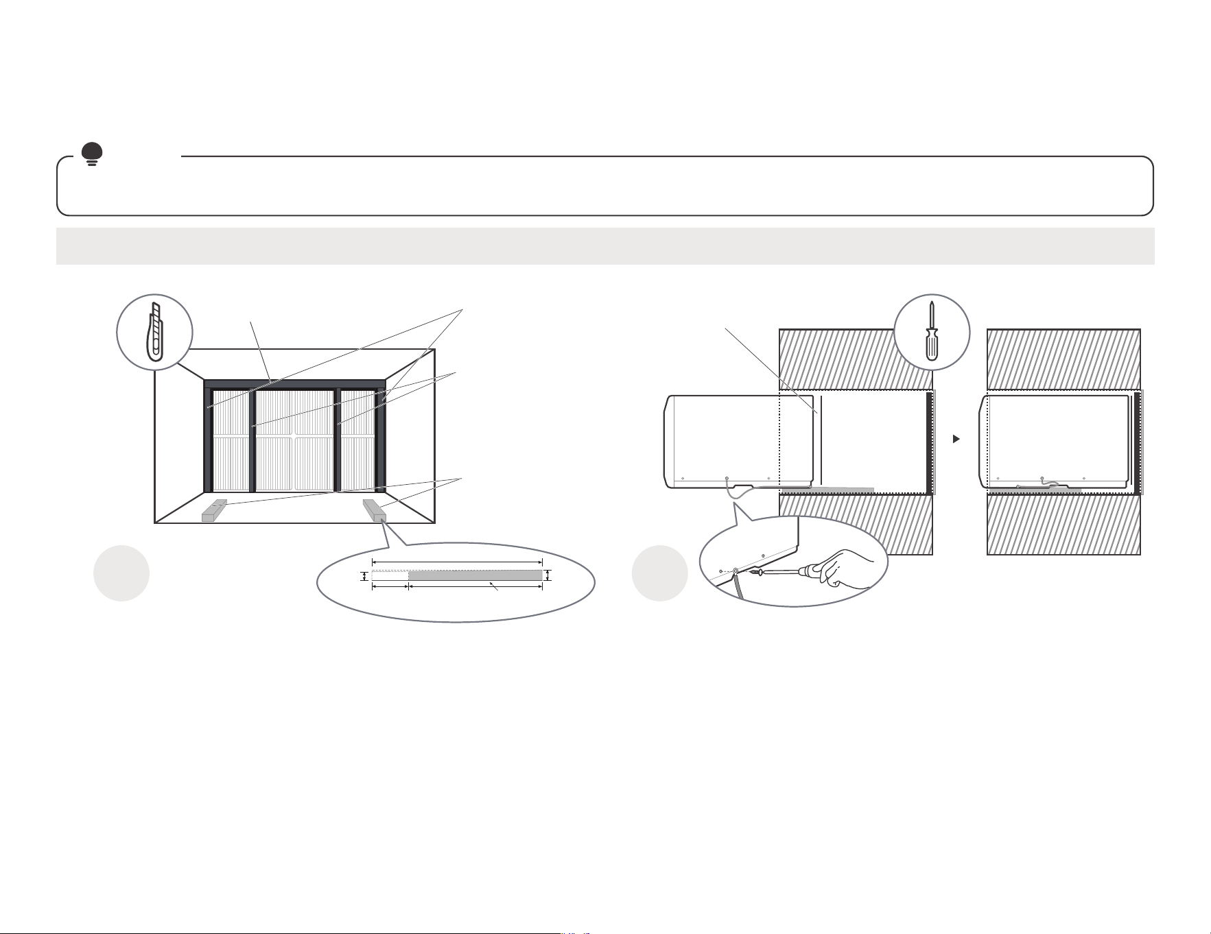
Paste the fixed Seal according to
the above figure and instructions.
The Seals and blocks shown above are all backed with glue.
You need to tear the paper to paste and fix it When installing.
Please be careful when you cutting.
Complete grounding connection and
product embedded wall sleeve.
Take out the unconnected end of the ground
wire in the wall sleeve, and then embed the
unit into the wall sleeve, as shown and then
hold on. Use a screwdriver to unscrew the
second screw below the unit and tighten the
ground wire connection(Make sure that the
toothed washer is against the cabinet).
Slide the unit completely
to the rear to ensure a
good seal, making sure
the ground wire does
not become tangled.
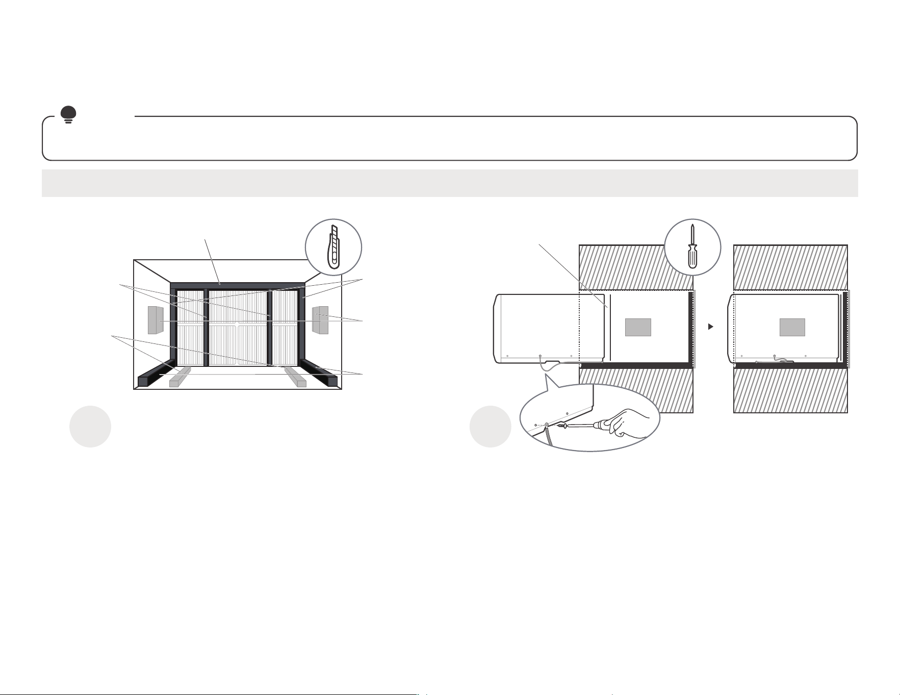
#1 Emerson(15" Deep)
11
installation guide
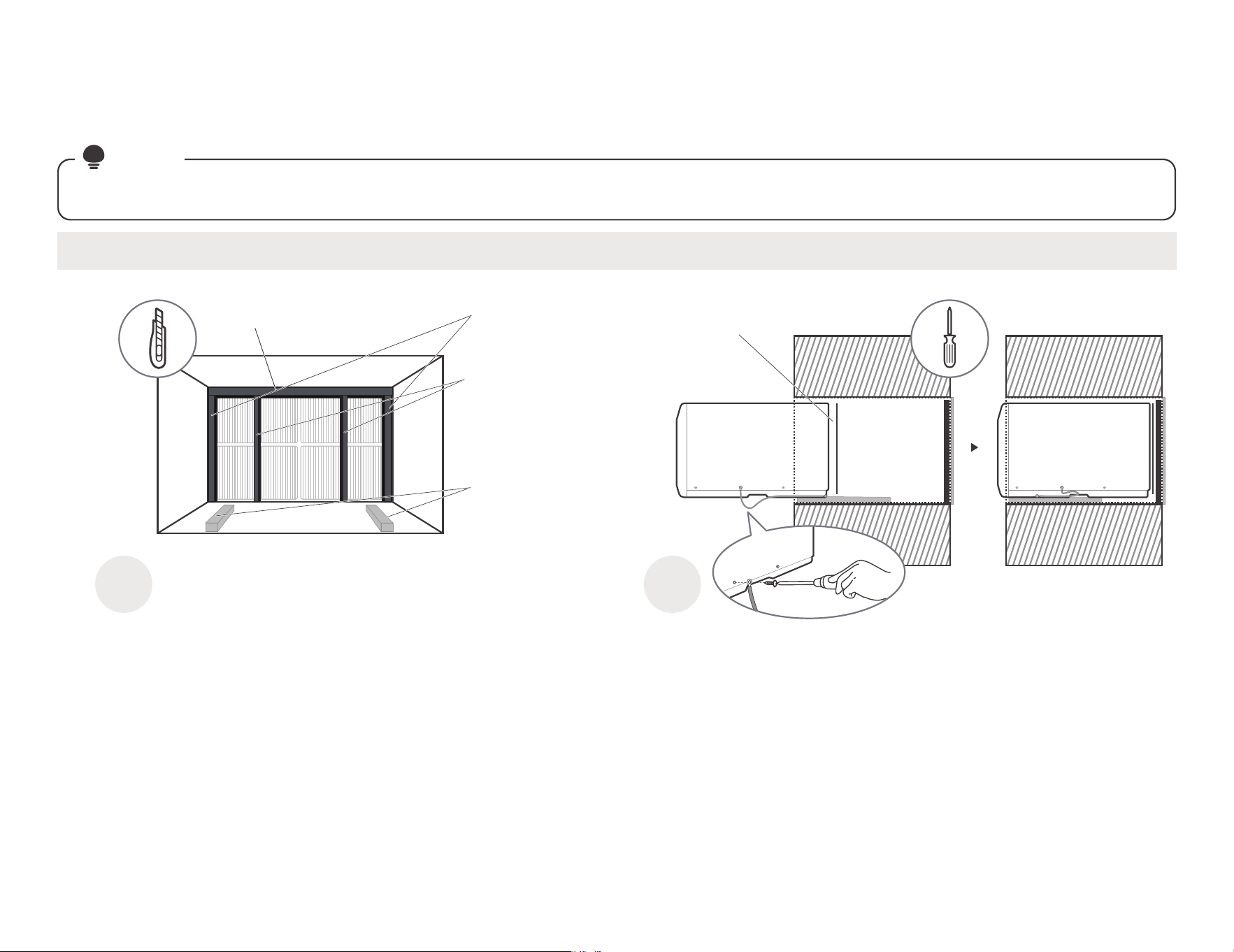
Complete the first installation step according to the wall cover installation guide (page 8) and aluminum grid installation guide (page 9) .
NOTE
Guide to installation before embedding the product into the wall
Tear the Seal(NO.13) paper from the
back, and attach it to the top of the
sleeve where it meets the aluminum
grille.
Cut the Seal(NO.12)
to a 14" high, Paste
on the left and right
sides of the sleeve.
Paste the support
blocks(NO.7) in the
center on both sides
of the wall sleeve.
Cut the Seal(NO.14)
to a 14" long, Paste
it on the sleeve left
and right sides of the
bottom edge.
Cut the
Seal(NO.13)
to a 14" high,
Attach it
vertically to the
grille as shown.
Cut the Tapered
Spacer Block
(NO.8) to a 14"
long, Paste it on
the sleeve of the
bottom.
Sleeve Front View
Don't forget to place the
plastic grille(NO.6) in the
wall sleeve between the
unit and the aluminum grille.
12
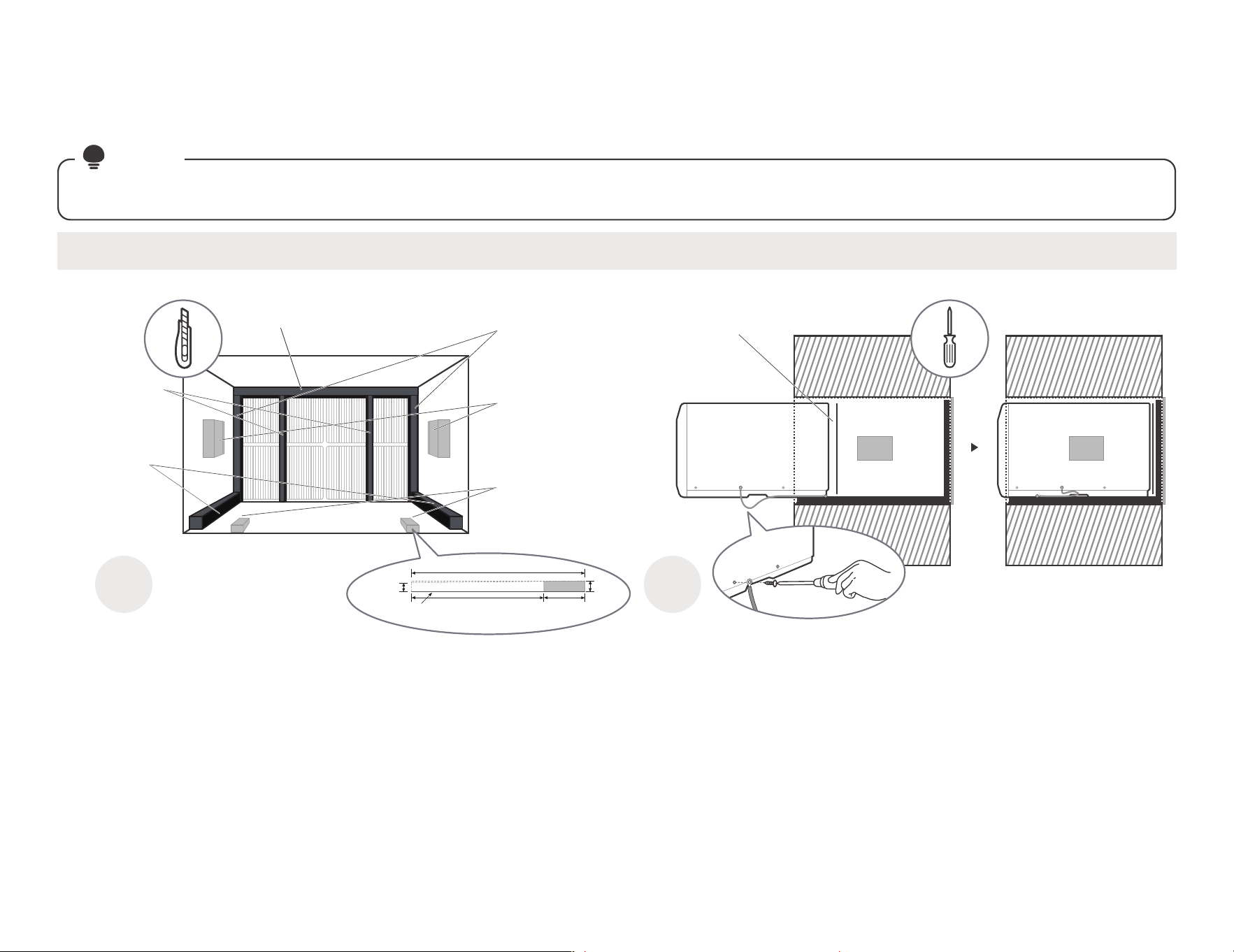
1 2
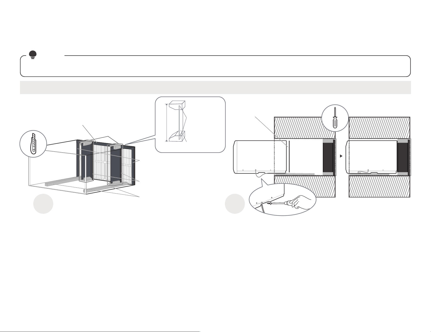
Paste the fixed Seal
according to the above
figure and instructions.
The Seals and blocks shown above are all backed with glue.
You need to tear the paper to paste and fix it When installing.
Please be careful when you cutting.
Complete grounding connection and
product embedded wall sleeve.
Take out the unconnected end of the ground
wire in the wall sleeve, and then embed the
unit into the wall sleeve, as shown and then
hold on. Use a screwdriver to unscrew the
second screw below the unit and tighten the
ground wire connection(Make sure that the
toothed washer is against the cabinet).
Slide the unit completely
to the rear to ensure a
good seal, making sure
the ground wire does
not become tangled.
#2 Fedders(19-3/4" Deep)
installation guide
Complete the first installation step according to the wall cover installation guide (page 8) and aluminum grid installation guide (page 9) .
NOTE
Guide to installation before embedding the product into the wall
Cut the Seal(NO.12)
to a 14" high, Paste
on the left and right
sides of the sleeve.
Paste the support
blocks(NO.7) in the
center on both sides
of the wall sleeve.
Cut the
Seal(NO.14)
to a 18" long,
Paste it on the
sleeve left and
right sides of
the bottom edge.
Cut the
Seal(NO.13)
to a 14" high,
Attach it
vertically to the
grille as shown.
Cut the Tapered Spacer
Block(NO.8), and Paste
it on the sleeve of the
bottom as shown
(This operation is to
allow the product to
drain properly).
Sleeve Front View
Don't forget to place the
plastic grille(NO.6) in the
wall sleeve between the
unit and the aluminum grille.
Tear the Seal(NO.13) paper from the
back, and attach it to the top of the
sleeve where it meets the aluminum
grille.
17"
4"Cut it
Protection
paper backing
Tapered Spacer Block 1"
3/4"

13
1 2
Paste the fixed Seal
according to the above
figure and instructions.
The Seals and blocks shown above are all backed with glue.
You need to tear the paper to paste and fix it When installing.
Please be careful when you cutting.
Complete grounding connection and
product embedded wall sleeve.
Take out the unconnected end of the ground
wire in the wall sleeve, and then embed the
unit into the wall sleeve, as shown and then
hold on. Use a screwdriver to unscrew the
second screw below the unit and tighten the
ground wire connection(Make sure that the
toothed washer is against the cabinet).
Slide the unit completely
to the rear to ensure a
good seal, making sure
the ground wire does
not become tangled.
#3 Fedders or Friedrich(16-3/4" Deep)
installation guide
Complete the first installation step according to the wall cover installation guide (page 8) and aluminum grid installation guide (page 9) .
NOTE
Guide to installation before embedding the product into the wall
Cut the Seal(NO.12)
to a 14" high, Paste
on the left and right
sides of the sleeve.
Paste the support
blocks(NO.7) in the
center on both sides
of the wall sleeve.
Cut the
Seal(NO.14)
to a 15" long,
Paste it on the
sleeve left and
right sides of
the bottom edge.
Cut the
Seal(NO.13)
to a 14" high,
Attach it
vertically to the
grille as shown.
Cut the Tapered Spacer
Block(NO.8), and Paste
it on the sleeve of the
bottom as shown
(This operation is to allow
the product to drain
properly).
Sleeve Front View
Don't forget to place the
plastic grille(NO.6) in the
wall sleeve between the
unit and the aluminum grille.
Tear the Seal(NO.13) paper from the
back, and attach it to the top of the
sleeve where it meets the aluminum
grille.
17"
2-1/2"2" 12-1/2"
Cut it
Protection
paper backing
1"
3/4"
Tapered Spacer Block

14
1 2
Paste the fixed Seal
according to the above
figure and instructions.
The Seals and blocks shown above are all backed with glue.
You need to tear the paper to paste and fix it When installing.
Please be careful when you cutting.
Complete grounding connection and
product embedded wall sleeve.
Take out the unconnected end of the ground
wire in the wall sleeve, and then embed the
unit into the wall sleeve, as shown and then
hold on. Use a screwdriver to unscrew the
second screw below the unit and tighten the
ground wire connection(Make sure that the
toothed washer is against the cabinet).
Slide the unit completely
to the rear to ensure a
good seal, making sure
the ground wire does
not become tangled.
#4 General Electra/Hotpoint(16-7/8" Deep)
installation guide
Complete the first installation step according to the wall cover installation guide (page 8) and aluminum grid installation guide (page 9) .
NOTE
Guide to installation before embedding the product into the wall
Cut the Seal(NO.12)
to a 14" high, Paste
on the left and right
sides of the sleeve.
Cut the Seal(NO.13)
to a 14" high,
Attach it vertically
to the grille as shown.
Cut the Tapered Spacer
Block(NO.8), and Paste
it on the sleeve of the
bottom as shown
(This operation is to allow
the product to drain
properly).
Sleeve Front View
Don't forget to place the
plastic grille(NO.6) in the
wall sleeve between the
unit and the aluminum grille.
Tear the Seal(NO.13) paper from the
back, and attach it to the top of the
sleeve where it meets the aluminum
grille.
17"
4"13"
Cut it
Protection
paper backing
Tapered Spacer Block 1"
3/4"

15
1 2
Paste the fixed Seal
according to the above
figure and instructions.
The Seals and blocks shown above are all backed with glue.
You need to tear the paper to paste and fix it When installing.
Please be careful when you cutting.
Complete grounding connection and
product embedded wall sleeve.
Take out the unconnected end of the ground
wire in the wall sleeve, and then embed the
unit into the wall sleeve, as shown and then
hold on. Use a screwdriver to unscrew the
second screw below the unit and tighten the
ground wire connection(Make sure that the
toothed washer is against the cabinet).
Slide the unit completely
to the rear to ensure a
good seal, making sure
the ground wire does
not become tangled.
#5 Sears or Carrier 51S Series(18-5/8" Deep)
installation guide
Complete the first installation step according to the wall cover installation guide (page 8) and aluminum grid installation guide (page 9) .
NOTE
Guide to installation before embedding the product into the wall
Cut the Seal(NO.12)
to a 15" high, Paste
on the left and right
sides of the sleeve.
Cut the Seal(NO.13)
to a 15" high,
Attach it vertically
to the grille as shown.
Paste the Tapered Spacer
Block(NO.8) on the sleeve
of the bottom as shown
(This operation is to allow
the product to drain
properly).
Sleeve Front View
Don't forget to place the
plastic grille(NO.6) in the
wall sleeve between the
unit and the aluminum grille.
Tear the Seal(NO.13) paper from the
back, and attach it to the top of the
sleeve where it meets the aluminum
grille.

16
#6 Whirlpool(17-1/8" Deep)
installation guide
Complete the first installation step according to the wall cover installation guide (page 8) and aluminum grid installation guide (page 9) .
NOTE
Guide to installation before embedding the product into the wall
1 2
Paste the fixed Seal
according to the above
figure and instructions.
The Seals and blocks shown above are all backed with glue.
You need to tear the paper to paste and fix it When installing.
Please be careful when you cutting.
Complete grounding connection and
product embedded wall sleeve.
Take out the unconnected end of the ground
wire in the wall sleeve, and then embed the
unit into the wall sleeve, as shown and then
hold on. Use a screwdriver to unscrew the
second screw below the unit and tighten the
ground wire connection(Make sure that the
toothed washer is against the cabinet).
Slide the unit completely
to the rear to ensure a
good seal, making sure
the ground wire does
not become tangled.
Cut the Seal(NO.12)
to a 15" high, Paste
on the left and right
sides of the sleeve.
Cut the Seal(NO.13)
to a 15" high,
Attach it vertically
to the grille as shown.
Cut the Tapered Spacer
Block(NO.8), and Paste
it on the sleeve of the
bottom as shown
(This operation is to allow
the product to drain
properly).
Sleeve Front View
Don't forget to place the
plastic grille(NO.6) in the
wall sleeve between the
unit and the aluminum grille.
Tear the Seal(NO.13) paper from the
back, and attach it to the top of the
sleeve where it meets the aluminum
grille.
17"
4"
13"
Cut it
Protection
paper backing
Tapered Spacer Block
1"
3/4"
17
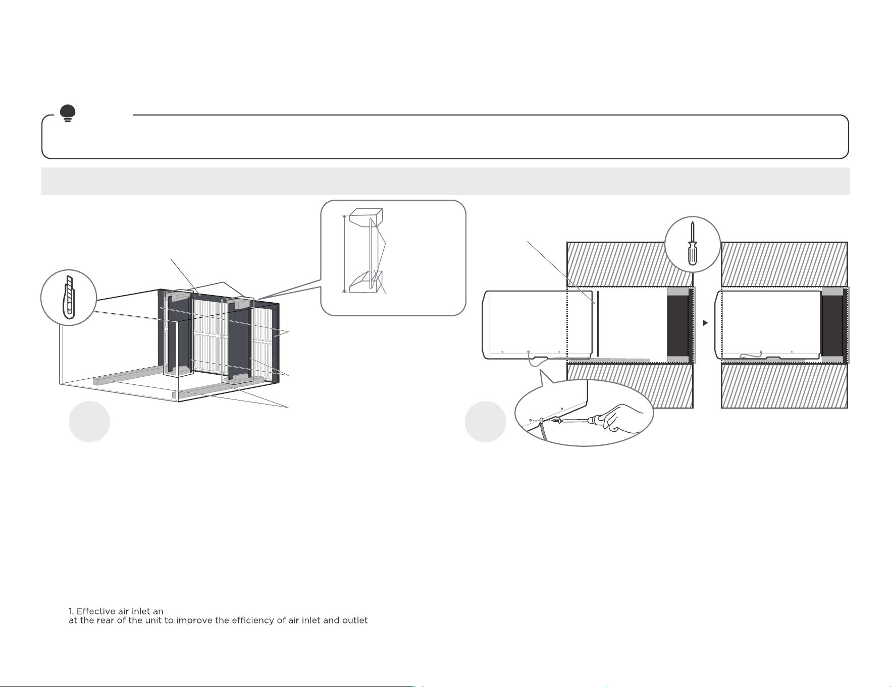
#7 Whirlpool(23" Deep)
installation guide
Complete the first installation step according to the wall cover installation guide (page 8) and aluminum grid installation guide (page 9) .
NOTE
Guide to installation before embedding the product into the wall
1 2
Paste the fixed Seal
according to the above
figure and instructions.
The Seals and blocks shown above are all backed with glue.
You need to tear the paper to paste and fix it When installing.
Please be careful when you cutting.
Complete grounding connection and
product embedded wall sleeve.
Take out the unconnected end of the ground
wire in the wall sleeve, and then embed the
unit into the wall sleeve, as shown and then
hold on. Use a screwdriver to unscrew the
second screw below the unit and tighten the
ground wire connection(Make sure that the
toothed washer is against the cabinet).
Slide the unit completely
to the rear to ensure a
good seal, making sure
the ground wire does
not become tangled.
Cut the Seal(NO.12) to a 15"
high, Paste on the left and
right sides of the sleeve.
Cut the Seal(NO.13) to
a 15" high, Attach it vertically
to the grille as shown.
Paste the Tapered Spacer
Block(NO.8) on the sleeve
of the bottom as shown
(This operation is to allow
the product to drain
properly).
Don't forget to place the
plastic grille(NO.6) in the
wall sleeve between the
unit and the aluminum grille.
Tear the Seal(NO.13) paper
from the back, and attach it
to the top of the sleeve where
it meets the aluminum grille.
For the sleeve with too
much depth, we need to
add centering/support
blocks(No. 7) and Plastic
Divider(No. 15). Please
refer to the figure for
installation.
NOTE:There are two benefits to adding the rear plastic partition:
d outlet interval between the air inlet and outlet grilles
2. Play the role of stabilizing unit under product working condition.
16-1/2"
You may need
to trim the
length to size.
The blocks
has card slots
into which the
plastic divider
can be inserted.

18
1 2
Paste the fixed Seal according to
the above figure and instructions.
The Seals and blocks shown above are all backed with glue.
You need to tear the paper to paste and fix it When installing.
Please be careful when you cutting.
Complete grounding connection and
product embedded wall sleeve.
Take out the unconnected end of the ground
wire in the wall sleeve, and then embed the
unit into the wall sleeve, as shown and then
hold on. Use a screwdriver to unscrew the
second screw below the unit and tighten the
ground wire connection(Make sure that the
toothed washer is against the cabinet).
Slide the unit completely
to the rear to ensure a
good seal, making sure
the ground wire does
not become tangled.
#8 White Westinghouse/Frigidaire/
Carrier 52F Series(16/17-1/2" Deep)
installation guide
Complete the first installation step according to the wall cover installation guide (page 8) and aluminum grid installation guide (page 9) .
NOTE
Guide to installation before embedding the product into the wall
Tear the Seal(NO.13) paper from the
back, and attach it to the top of the
sleeve where it meets the aluminum
grille.
Cut the Seal(NO.12)
to a 14" high, Paste
on the left and right
sides of the sleeve.
Cut the Seal(NO.14)
to a 14" long, Paste
it on the sleeve left
and right sides of the
bottom edge.
Cut the
Seal(NO.13)
to a 14" high,
Attach it
vertically to the
grille as shown.
Sleeve Front View
Don't forget to place the
plastic grille(NO.6) in the
wall sleeve between the
unit and the aluminum grille.

19
#9 White Westinghouse or Frigidaire(22" Deep)
installation guide
Complete the first installation step according to the wall cover installation guide (page 8) and aluminum grid installation guide (page 9) .
NOTE
Guide to installation before embedding the product into the wall
1 2
Paste the fixed Seal
according to the above
figure and instructions.
The Seals and blocks shown above are all backed with glue.
You need to tear the paper to paste and fix it When installing.
Please be careful when you cutting.
Complete grounding connection and
product embedded wall sleeve.
Take out the unconnected end of the ground
wire in the wall sleeve, and then embed the
unit into the wall sleeve, as shown and then
hold on. Use a screwdriver to unscrew the
second screw below the unit and tighten the
ground wire connection(Make sure that the
toothed washer is against the cabinet).
Slide the unit completely
to the rear to ensure a
good seal, making sure
the ground wire does
not become tangled.
Cut the Seal(NO.12) to a 14"
high, Paste on the left and
right sides of the sleeve.
Cut the Seal(NO.13) to
a 14" high, Attach it vertically
to the grille as shown.
Paste the Tapered Spacer
Block(NO.8) on the sleeve
of the bottom as shown
(This operation is to allow
the product to drain
properly).
Tear the Seal(NO.13) paper
from the back, and attach it
to the top of the sleeve where
it meets the aluminum grille.
For the sleeve with too
much depth, we need to
add centering/support
blocks(No. 7) and Plastic
Divider(No. 15). Please
refer to the figure for
installation.
NOTE:There are two benefits to adding the rear plastic partition:
d outlet interval between the air inlet and outlet grilles
2. Play the role of stabilizing unit under product working condition.
15-1/4"
You may need
to trim the
length to size.
The blocks
has card slots
into which the
plastic divider
can be inserted.
Don't forget to place the
plastic grille(NO.6) in the
wall sleeve between the
unit and the aluminum grille.

20
You can installing aluminum grille at first.
installation guide
The previous directions are the preferable way to mount the new Aluminum Grill. The units performance is slightly better and the possibility
of draughts is reduced. As a last resort, direct mounting of the grille to the unit can be considered (the installation tutorial follows).
The Aluminum Grille must be installed prior to inserting the unit into the sleeve.
NOTE
1 2
Paste the Seals(NO.12)
as shown.
Paste the Seals(NO.12) as shown. It provides a
safe distance between the fins and the Aluminum
from touching.
Install the unit with the Aluminum Grille and
embed it into the Wall Sleeve.
Line up the Aluminum Grille with
the rear hole of the unit as shown,
then tighten and secure it using
Screws and Screw Washer(NO.16).
The protruding side of the
aluminum grille fin needs to be
mounted outwards.
Screw(NO.16)
Paste the
Seals(NO.12)
1/8 Hole
Grille &
Flange
If the unit has not been pre-drilled, carefully drill
four 1/8" holes through the grille and into the side
flange of the unit, then fasten it with
Screws(NO.16). Be careful not to drill into the
copper heat exchanger coils.
Finally, insert the unit into the sleeve.
21
Finally, do some cosmetic work on your product.
installation guide
1
Do some cosmetic work.
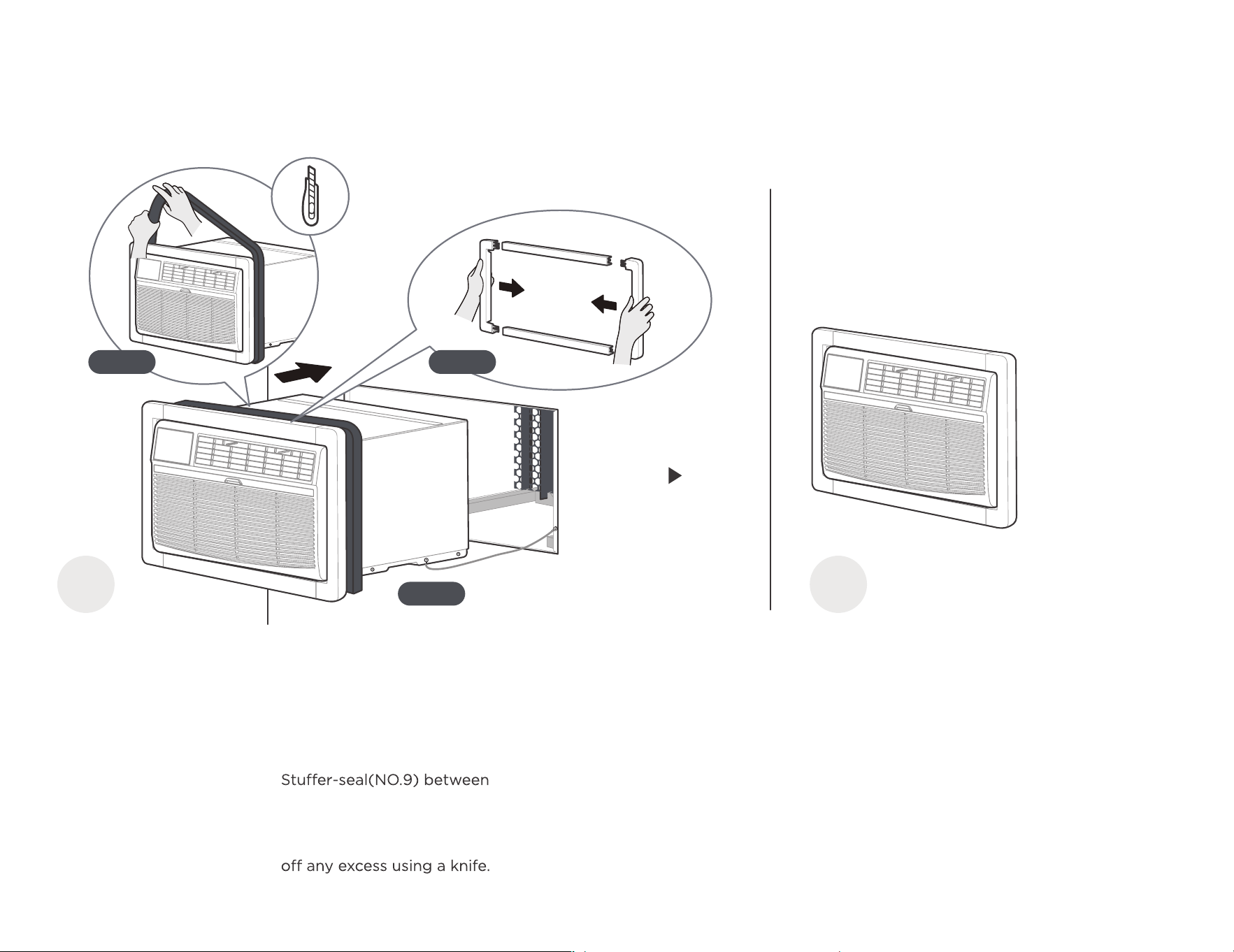
Step 1: Assemble the Trim
Frame(NO.2) by inserting
top and bottom pieces
into side pieces(NO.3), and
embed it into the unit flush
with the front panel.
2
The installation
is complete.
Congratulations on the installation, but
you're not done yet. Take a break! And
then, get to know your product better.
Step 2: Install the Long
the wall-sleeve and the unit.
Wrap the foam tightly around
the fuselage and carefully cut
Step 3: Slide the frame, seal
and unit carefully into the Wall
Sleeve for internal fixation,
taking care that the grounding
wire is also properly placed
and not damaged.
Step 2
Step 3
Step 1
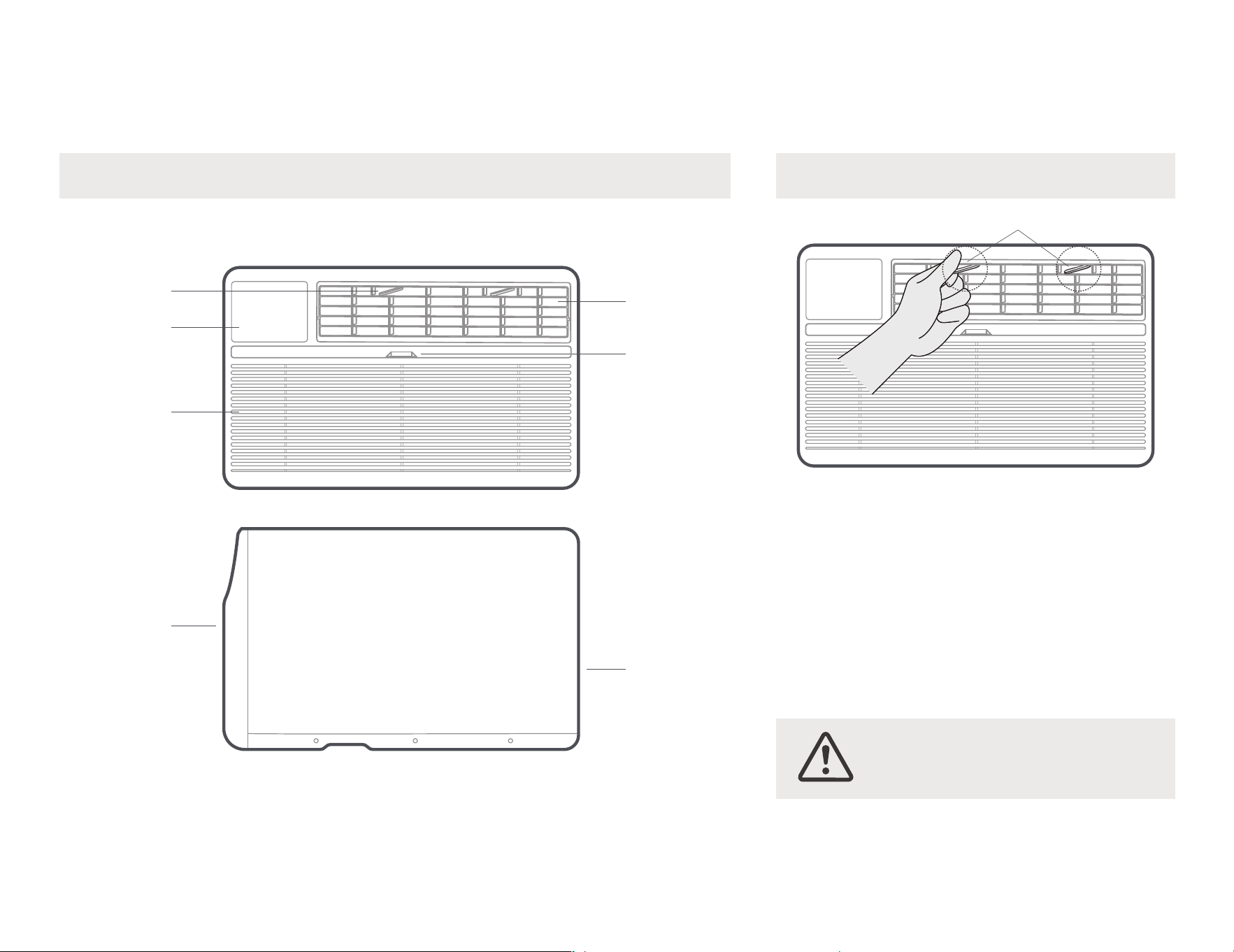
CAUTION: Do not stick your fingers
in the air outlet, it may cause an injury.
Get to know your AC.
AC unit overview
front
panel
Rear
Condenser
Vents
22
Levers
Filter
handshandle
Center handles
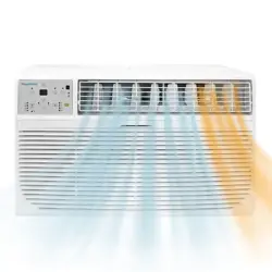
Air directional louvers control air flow direction.Your
air conditioner has the 4-way directional system
described below.The louvers will allow you to direct
the air flow Up or Horizontal, and Left or Right
throughout the room as needed.Use the center
handles to adjust the air directional louvers
side-to-side until the desired Left or Right direction
is obtained.Pivot horizontal louvers with your
fingertips until the desired Up or Horizontal
direction is obtained.
Adjust the Air DirectionComponents of the product
Grille
Front Intake
Display
Air Direction
23
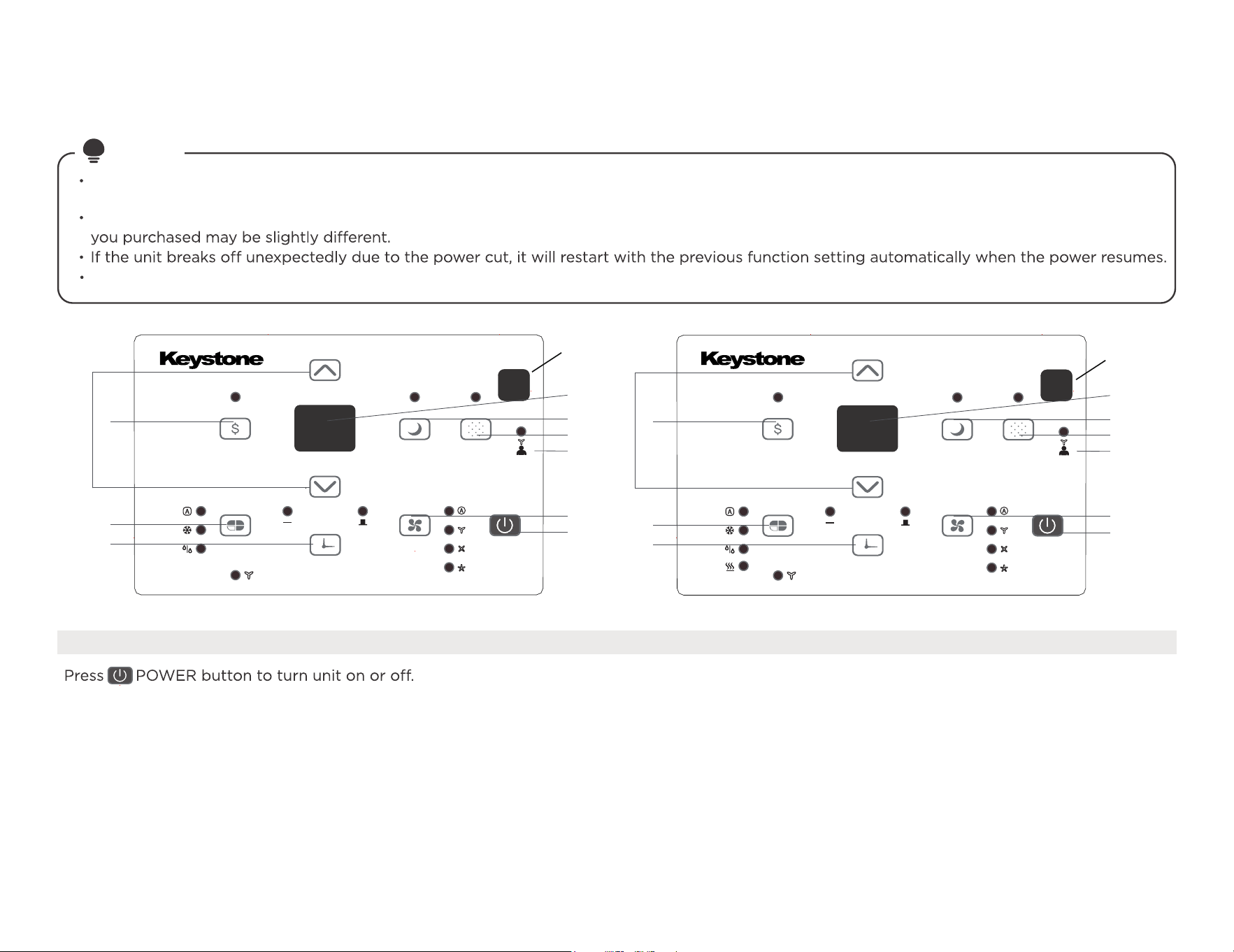
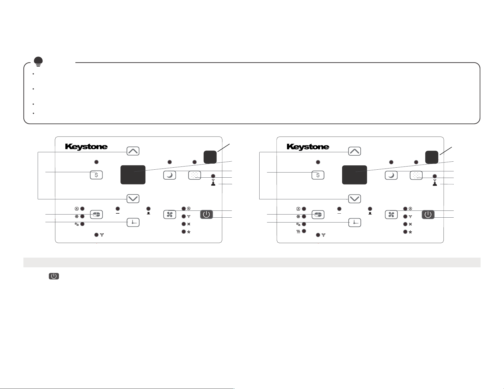
1. TO TURN UNIT ON OR OFF:
NOTE: The unit will initiate automatically the Energy Saver function under Cool, Dry, Auto(only Auto-Cooling and Auto-Fan) modes.
Get to know the features.
ELECTRONIC CONTROL OPERATING
INSTRUCTIONS
Before you begin, thoroughly familiarize yourself with the control panel as shown below and all its functions, then follow the symbol for the
functions you desire. The unit can be controlled by the unit control alone or with the remote.
NOTE
This control panel is based on the typical model. Not all the functions describing in this manual are available for all the models.The machine
HEAT function for heating models only.
6
8
9
2
1
3
4
5
10
7
6
8
9
2
1
3
4
5
10
7
RECEPTOR
REMOTE SIGNAL
RECEPTOR
REMOTE SIGNAL
24
ELECTRONIC CONTROL OPERATING INSTRUCTIONS
5. CHECK FILTER FEATURE:
Only section.
maintained anywhere between 62°F(17°C) and 86°F(30°C). If you want the display to read the actual room temperature, see To Operate on Fan
NOTE: Press or hold either UP or DOWN button until the desired temperature is seen on the display. This temperature will be automatically
Press
/
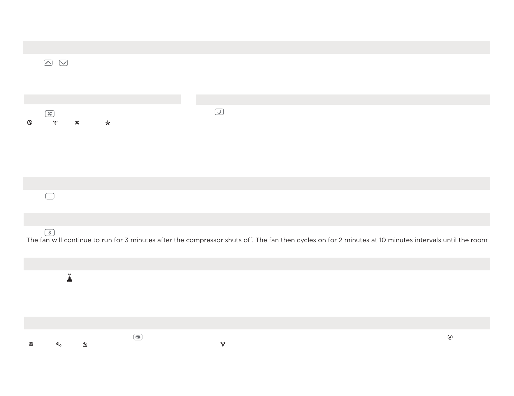
UP/DOWN button to change temperature setting.
2. TO CHANGE TEMPERATURE SETTING:
Low automatically.
On Dry mode, the fan speed is controlled at
speed can not be adjusted under HEAT mode.
mode is shifted. For some models, the fan
Each time the button is pressed, the fan speed
Auto,
Low,
Med
or
High.
3. TO ADJUST FAN SPEEDS:
pressing the Sleep button again.
programmed. The Sleep mode program can be cancelled at any time during operation by
temperature. This ends the Sleep mode and the unit will continue to operate as originally
This new temperature will be maintained for 7 hours before it returns to the originally selected
anadditional 30 minutes.
The temperature will then increase (cooling) or decrease(heating) by an other 2°F/1°C after
increase (cooling) or decrease (heating) by 2°F/1°C 30 minutes after the mode is selected.
Press Sleep button to initiate the sleep mode. In this mode the selected temperature will
4. SLEEP FEATURE:
Press Energy saver button to initiate this function. This function is available on COOL, DRY, AUTO (only AUTO-COOLING and AUTO-FAN) modes.
6. ENERGY SAVER FEATURE:
will illuminate after 250 hours of operation. To reset after cleaning the filter, press the Check Filter button and the light will go off.
Press Check Filter button to initiate the feature. This feature is a reminder to clean the air filter for more efficient operation. The LED light
mode is selected. The unit will initiate automatically the Energy Saver function under Cool, Dry, Auto (only Auto-Cooling and Auto-Fan) modes.
To choose operating mode, press Mode button. Each time you press the button, a mode is selected in a sequence that goes from
8. TO SELECT THE OPERATING MODE:
Me mode has ended.
the Follow Me button again. If the unit does not receive the Follow Me signal during any 7 minutes interval, the unit will beep to indicate the Follow
remote display is actual temperature at its location. The remote control will send this signal to the air conditioner every 3 minutes interval until press
temperature control at its location. To activate the Follow Me feature, point the remote control towards the unit and press the Follow Me button. The
This feature can be activated from the remote control ONLY. The remote control serves as a remote thermostat allowing for the precise
7. FOLLOW ME FEATURE:
temperature is above the set temperature, at which time the compressor turns back on and Cooling Starts.
Cool, Dry, heat (cooling only models without) and Fan. The indicator light beside will be illuminated and remained on once the
Auto,
Press to select the Fan Speed in four steps
To operate on Auto feature:
When you set the air conditioner in AUTO mode, it will automatically select cooling, heating (cooling only models without), or fan only operation
depending on what temperature you have selected and the room temperature.
The air conditioner will control room temperature automatically round the temperature point set by you.
The air conditioner will control room temperature automatically round the temperature point set by you.
In this mode, the fan speed cannot be adjusted, it starts automatically at a speed according to the room temperature.
To operate on Dry mode:
In this mode, the air conditioner will generally operate in the form of a dehumidifier. Since the conditioned space is a closed or sealed area,
some degree of cooling will continue.
25
To operate on COOL mode:
Choose Cool Mode to set the cooling function. Use the Up and Down buttons to choose the desired temperature.
When Cool Mode is selected, the fan speed can be adjusted by pressing the fan button.
To operate on HEAT mode
(cooling only models are excluded) :
Choose Heat mode to start heating operation. Use Up and Down buttons to set the desired temperature.
Press the fan button to select the fan speed. For some models, the fan speed can't be adjusted.
To operate on Fan Only:
Use this function only when cooling is not desired, such as for room air circulation or to exhaust stale air(optional)-Remember to open the
During this function, the display will show the actual room temperature, not the set temperature as in the cooling mode.
In Fan only mode, the temperature is not adjusted.
ELECTRONIC CONTROL OPERATING INSTRUCTIONS
HS-Electric heating sensor error-
Unplug the unit and plug it back in. If error
repeats, call for service.
CS-The sensor of the outdoor unit condenser is
faulty-Unplug the unit
and plug it back in. If error repeats,
call for service.
oS-Room temperature sensor error-
Unplug the unit and plug it back in. If error
repeats, call for service.
E3-The fan stall error-Unplug the unit and plug it
back in. If error repeats,
call for service.
E0-Failure of EEPROM parameter-
Unplug the unit and plug it back in. If error
r
epeats, call for service.
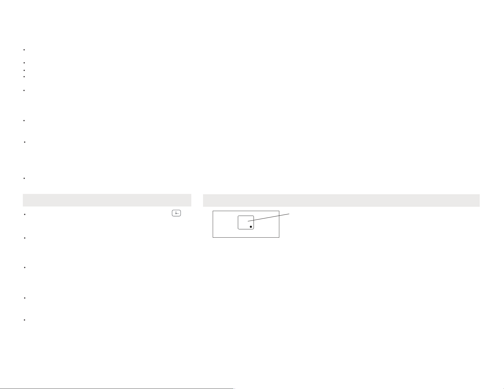
10. DISPLAY:
9. TIMER: AUTO START/STOP FEATURE:
Shows the set temperature in "°C" or
"°F " and the Auto-timer settings.
While on Fan only mode, it shows the
room temperature. If the room
temperature is too high or low, it will
display“HI” or “LO”.
Displays
Error codes:
AS-Room temperature sensor error-
Unplug the unit and plug it back in.
If error repeats, call for service.
ES-Evaporator temperature sensor
error-Unplug the unit and plug it back
in. If error repeats, call for service.
previous temperature setting or room temperature
system will automatically revert back to display the
The selected time will register in 5 seconds, and the
will count down the time remaining until start.
then at 1 hour increments up to 24 hours.The control
Auto time by 0.5 hour increments, up to 10 hours,
Press or hold the UP or DOWN button to change the
is initiated.
illuminates. It indicates the Auto Stop program
Timer button again, the TIMER OFF indicator light
When the time of TIMER ON is displayed, press the
indicatesthe Auto Start program is initiated.
button, the TIMER ON indicator light illuminates. It
When the unit is on or off, first press Timer
timed program.
timer setting to 0.0 will cancel theAuto Start/Stop
Turn the unit ON or OFF at any timeor adjusting the
display).
26
1
3
One more thing
Your AC may look Normal Sounds /
Sound Performance
Additional Notes
All the illustrations in this manual are
for explanation purpose only. Your air
The actual shape shall prevail.
high pitched chatter during the
cooling cycle.
High Pitched Chatter
At the front of the unit, you may hear the
sound of rushing air being moved by the fan.
Sound of Rushing Air
“Gurgling or hissing” noise may be heard
due to refrigerant passing through
evaporator during normal operation.
Gurgle/Hiss
Unit may vibrate and make noise because
of poor wall or window construction or
incorrect installation.
Vibration
Droplets of water hitting condenser during
normal operation may cause “pinging or
switching” sounds.
Pinging or Switching
2
Additional things
you should know.
Now that you have mastered the operating
procedure, here are more features in your
control that you should become
familiar with.
The Cool circuit has an automatic 3 minutes
and on quickly. This prevents overheating
of the compressor and possible circuit
breaker tripping.The fan will continue to
run during this time.
The control is capable of displaying
temperature in degrees Fahrenheit or
degrees Celsius. To convert from one to
the other, press and hold the Left and
Right Temp/Timer buttons at the same
time, for 3 seconds.

27
How to clean & change your filter.
Cleaning & maintenance
Air Filter Cleaning
The air filter should be checked at
least once a month to see if cleaning
is necessary. Trapped particles in the
filter can build up and cause an
accumulation of frost on the
cooling coils.
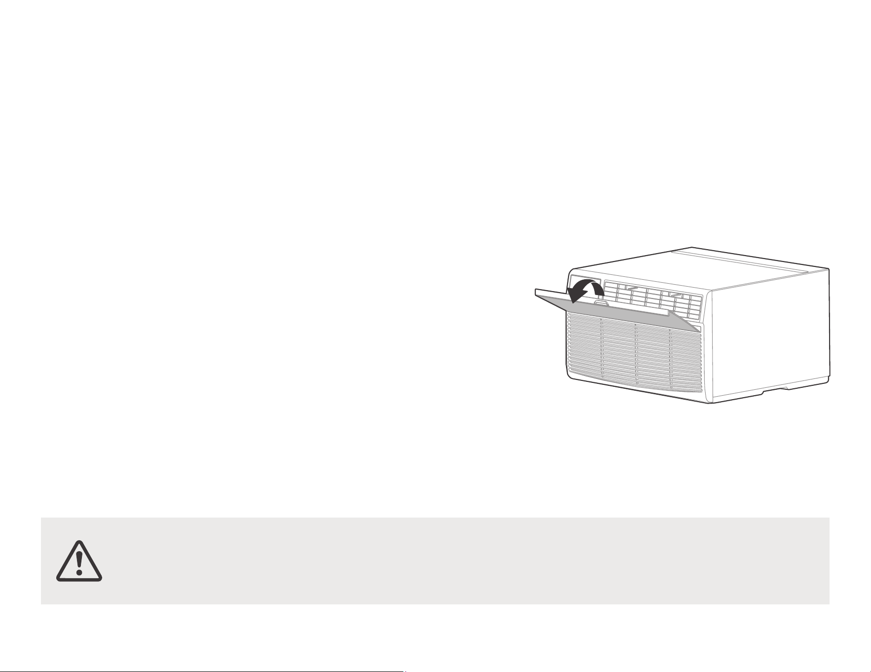
• Take the filter by the center and pull
up and out.
• Wash the filter using liquid
dishwashing detergent and warm
water. Rinse filter thoroughly. Gently
shake excess water from the filter.
Be sure the filter is thoroughly dry
before replacing. Or, instead of
washing you may vacuum the filter
clean.
Note: Never use hot water over
40°C(104°F) to clean the air filter.
Never attempt to operate the unit
without the air filter.
Energy Saving Note
In order to reach the maximum energy
saving and comfort, it is recommended
to use a cover to insulate the unit when
the unit is not in use. The recommended
size for the unit is 24.4"x14.8"x2.2"
(WxHxD).
Check the air filter at least once
a month to see if cleaning is necessary.
Be sure to unplug the air conditioner to
prevent shock or fire hazard. The cabinet
and front may be dusted with an oil-free
cloth or washed with a cloth dampened in
a solution of warm water and mild liquid
dishwashing detergent. Rinse thoroughly
and wipe dry.
Never use harsh cleaners, wax or polish on
the cabinet front.
Be sure to wring excess water from the
cloth before wiping around the controls.
Excess water in or around the controls may
cause damage to the air conditioner.
Plug in air conditioner.
•
•
•
•
Cabinet Cleaning
CAUTION: Clean your air conditioner occasionally
to keep it looking new. Be sure to unplug the unit
before cleaning to prevent shock or fire hazards.
CAUTION: If you plan to store the air conditioner during the winter,
remove it carefully from the window according to the installation
instructions. Cover it with plastic or return it to the original carton.

28
Problem Solving
TROUBLESHOOTING
Before calling for service, review this list. It may save your time and expense. This list includes common occurrences that are not the result of
defective workman-ship or materials in this appliance.
Air conditioner
does not start.
Wall plug disconnected. Push plug firmly into wall outlet.
House fuse blown or circuit breaker tripped. Replace fuse with time delay type or reset circuit breaker.
Plug Current Device Tripped. Press the RESET button.
Power is OFF. Turn power ON.
Air from unit does
not feel cold
enough.
Room temperature below 62°F(17°C). Cooling may not occur until room temperature rises above 62°F(17°C).
Temperature sensing behind air filter element touching cold coil. Keep it from the cold coil.
Set to a Lower temperature.
Compressor stopped when changing modes. Wait for 3 minutes after set to the COOL mode.
Air conditioner
cooling, but room
is too warm- ice
forming on cooling
coil behind
decorative front
.
Outdoor temperature below 64°F(18°C). To defrost the coil, set FAN ONLY mode.
Air filter may be dirty. Clean filter. Refer to Care and Cleaning section. To defrost, set to FAN ONLY mode.
Thermostat set too cold for night-time cooling. To defrost the coil, set to FAN ONLY mode. Then, set temperature to a
Higher setting.
Problem Solution
Air conditioner
rapidly
Dirty air filter- air restricted. Clean air filter.
Outside temperature extremely hot. Set FAN speed to a Higher setting to bring air past cooling coils more frequently.

29
Remote Sensing
Deactivating
Prematurely (Only
remote models)
Remote control not located within range. Place remote control within 20 feet and pointed in the general direction of
the air conditioner unit.
Remote control signal obstructed. Remove obstruction.
Problem Solution
Problem Solving
Air conditioner
cooling, but room
is too warm- NO
ice forming on
cooling coil behind
decorative front.
Noise when unit is
cooling
Dirty air filter- air restricted. Clean air filter. Refer to Care and Cleaning section.
Temperature is set too High, set temperature to a Lower setting.
Air directional louvers positioned improperly. Position louvers for better air distribution.
Front of units is blocked by drapes, blinds, furniture, etc. - restricts air distribution. Clear blockage in front of unit.
Doors, windows, registers, etc. Open- cold air escapes. Close doors, windows, registers.
Unit recently turned on in hot room. Allow additional time to remove Stored heat from walls, ceiling, floor and furniture.
Air movement sound. This is normal . If too lou
d, set to a slower FAN setting.
Window vibration - poor installation. Refer to installation instructions or check with installer.
Water dripping
OUTSIDE when
unit is cooling.
Unit removing large quantity of moisture from humid room. This is normal during excessively humid days.
Room too cold
Set temperature too low. Increase set temperatur.
Water dripping
OUTSIDE when
unit is cooling.
Improper installation. Tilt air conditioner slightly to the outside to allow water drainage. Refer to installation
instructions - check with installer.
The design and specifications are subject to change without prior notice for product improvement. Consult with the sales agency or manufacturer
for details. Any updates to the manual will be uploaded to the service website, please check for the latest version.
MNS: HLONPS:MSD9
Rdqhd SSV
KSTAT08-1E
KSTAT10-1E
KSTAT10-2E
KSTAT12-1E
KSTAT12-2E
KSTAT14-2D
KSTAT08-1HD
KSTAT10-2HD
KSTAT12-2HD
KSTAT14-2HD
Modelo:
800-849-1112
|
AIRE ACONDICIONADO DE PARED

!
"
#
$%&
'()*+
+,)-.,+
/)+/(0-+
$1% 2#0!
!"! 20
$ 2#
2#


/0
/5
17
11
12
/6
0 /
,
!
16

/0
!!
"!
"!#
!!
" !!!
!#$
!
" !!!
"#$%
%$&'(

/1
%-&
'!()!
%-'
!)
#'
*$%
$!#!
"
'-)
-'-)*
-+
'-)!'-
%'-)#!
%'-
'!
&%( *
'-
)% -
'-)
%'-
,!%!
)
%-'
-)!*
!
(
-
%!!'-
(*)#
%'-
#
-
-%
$(+!-
)!%
"
#)!
!!
'-)#)
*
!
&!
-"
!
!
%-
)'
!'*-
#!
%#"#$
%
!(%.(

/2
/
%
0(1
01
/
%
0(1
O
O
12,65 E. B,4,13
01
O
21,7/ E.
O
/,16 B
O O O O
53,0/8234567’53,014234589
(
O
51,8/ E.
O
06,21 B
!
"$$
)
)
+-
'0
!'$
!$
!-
" !
!
*
$%!!
#!
!
)9
%
%
%!1
%(
; ( %+*
'$
técnico cualificado.
la clavija de alimentación y póngase en contacto con un
y desconecte el disyuntor. lSepare el suministro desenchufando
Si entra agua en el aparato, apáguelo en la toma de corriente
+
0!"#
+%
'- )!
':!
!
%')
)
Puede provocar fallos en el producto o un incendios.
cuando no vaya a utilizar la unidad durante mucho tiempo.
descargas eléctricas y daños. Apague el interruptor principal
Sujete el enchufe por la cabeza al sacarlo. Puede provocar
/3
!<0'
%
$
<.=>
%
!
' *
$
%
'
-
!!1
&/$%<.=>*
<0!
<0!
’!'$$%?
)
(
!
-
)$
%
-
"'
'-
>!'$!'!
%!'-
$
!%*!
#>!'
)!%!+
)(
*$+
)!
/4
)!+*
+'-
!'
!
*!1
>!'
!%
!
'
>!
!
@%
->
!
#
!'-)
()!
-
%&
,
>)0&<>"AB><.>"C.A<0<>=>D/"E0<A//&>=">&/>>@.">)<@F><A)A>"&"A0,>
)/0>9 !
(!
!
##
Bnloqdrnq
'
-
$
L/AC L/L1/L-IN
N/AC N/L2/N-IN

./01&(
!
)!
;?-
)%
,#
>!
#
0!
/
/5
0
3
6
4
5
2
1
7
8
0/ 00 01
04
02
03
05
06
07
08
)1;4G(735G(46G?
)1;4G(4439G(46G?
=;$?H9
’6.7 w0,0.7 w06 (
=.’$?
H6;6439G(7439G(4439G?
)1;4G(735G(98G?
)2;4G(4439G(98G?
&)1;435G(6439G(46439G?
)1;4G(736G(46G?
0
2
1
4
3
6
5
7
0/
00
01
02
03
04
05
06
07
08
8
.>>
,<;%?H9
,<’?H9
;(
<>
<;435G(6439G(46439G?
0)3>0)3
0’()3
000
>&00
"#$%
&"'
!() * $
0$
<H4;4G(4439G(56G?
/6
$2(
3$/%1$'(
"113 03
07 %;%(-A
!
#
!#
*-
">+
5/
LWmtWk
+%
@
%%
"
'
'
14,0.1
15
14,6.7
16
14,2.3
15,2.3
16
04,0.3
04,4.7
05,0.1
05,2.3
05,6.7
04,2.3
05,2.3
08,2.3
05,2.3
07,4.7
06,0.7
12
05.06,0.1
11
06,0.7
n 12
05,2.3
n 08,2.3
07,4.7
04
05,2.3
0
Vghsd,Vdrshmfgntrd
EqhfhcYhqd
Eqhdcqhbg
BYqqhdq ’Rdqhd 41E(
BYqqhdq ’Rdqhd 40R(
FdmdqYk Dkdbsqhb.
Gnsonhms
Vghqkonnk
RdYqr.Jdmlnqd
Edccdqr.Dldqrnm
Dldqrnm.Edccdqr
Dldqrnm"0
"1
"2
"3
"4
"5
"6
"7
"8
Edccdqr
Edccdqr.
Eqhdcqhbg
Vghsd,Vdrshmfgntrd.
EqhfhcYhqd.
BYqqhdq’Rdqhd 41E(
Vghsd,Vdrshmfgntrd.
EqhfhcYhqd
FdmdqYk Dkdbsqhb.
Gnsonhms
RdYqr.
BYqqhdq’Rdqhd 40R(
Vghqkonnk
Vghqkonnk
:8!+-
0!
%%
%
,
40bl
’1/ (
,
40bl
’1/ (
,011
05’3,02
.05 5,4.
05 (
'%
*
!#!
-
!%
%''
<
"
05,2.7
05,2.7
n 11
05 *06,0.1
*
04
*

$'-
'
/7
!9
0$>>
%!
>>
'$&=
)#+-
I!12,3”
0
)
Eqnms
.)A&>&
'10"
<>>
;(-";?
&%!
0.7 .00
0;)07(*>&;)08(
$
>!
0.7
0
,(2
#!
$
';?
!!0.7
'$
2 (%$
0(%
%
$'
!$
(
' ’/*&(
%

/8
0 ;?>!
$!
"+(!
'&
&$(
<(
!
<
"(
"
,!
%!
0.7 -
2
2
’$$4
3$
-
0
&$-
1
5$'4
&$-
2
&!
;)4J?
0
!
&!
%
0.7 -

0/
(
$
"
#("%
-
"86060-7&$
HLONPS:MS
@
!$!
"
"%
!+-
'
*'
;!
!6
?#$
-
!
!1/-
!%"%
#

0 1
3&38
(
"!
)!!#-
%!
"$1'
$(
(
!
!!
.!
(
’>!
'!?
&
!
!
"0$’04 *4
00
#
!+’!7(!+’!8(-
#$
&!;)/47?'
!
;)/49?
03 *'!
$
!
;)/J?
;)/46?
!03 *'
!$
%
;)/47?
03 *'!
;)/
5?!
03 *'!
%
-
*'
)
;)/K?
-

01
0 1
"$1'
$(
&
!
!
#
!+’!7(!+’!8(-
#$
;)/49?
03 *'!
$
!;)/
J?
;)/46
?!
07 *'!
$
%
;)/47
?03 *
'!
;)/
5?'!
%;
?
*'
)
;)/K?
-
&!;)/47?
'!
06
3
= 0
2.3
GL
%!
)!!#-
"!
3&938
'!?
’>!
(
.!
!!
!
(
"1 - ’08,2.3 *4

02
0 1
"$1'
$(
(
!
!!
.!
(
’>!
'!?
&
!
!
#
!+’!7(!+’!8(-
#$
;)/49?
03 *'!
$
!;)/
J?
;)/46
?!
04 *'!
$
%
;)/47
?03 *
'!
=
;)/5?'!!
%’
?
*'
)
;)/K?
-
&!;)/47?
'!
06
1,0.1 1 01,0.1
0
2.3
=
%!
)!!#-
"!
3&938
"2 --0 ’05,2.3 *4

03
0 1
3&9
38
-
"!
)!!#-
%!
"$1'
$(
(
!
!!
.!
(
’>!
'!?
&
!
!
#
!+’!7(!+’!8(-
#$
;)/49?
03 *'!
$
;)/47?
03 *%+
=
;)/5?'!!
%’
?
*'
)
;)/K?
-
&!;)/47?
'!
06
3 02
=
0
2.3
L
"3 : ’05,6.7 *4
04
0 1
3&9
38
-
"!
)!!#-
%!
"$1'8
$(
(
!
!!
.!
(
’>!
'!?
&
!
!
#
!+’!7(!+’!8(-
#$
;)/49?
04 *'!
$
!
;)/47?
04 *%+
!=
;)/5?!%
’
?
*'
)
;)/K?
-
&!;)/47?
'!
"4 ;< ’07,4.7 *4
05
#
!+’!7(!+’!8(-
#$
0 1
3&9
38
-
"!
)!!#-
%!
"$1'8
$(
(
!
!!
.!
(
’>!
'!?
&
!
!
;)/49?
04 *'!
$
!
;)/47?
04 *%+
=
;)/5?'!!
%’
?
*'
)
;)/K?
-
&!;)/47?
'!
06
3
02
=
0
2.3
"5 60 ’06,0.7 *4

06
#
!+’!7(!+’!8(-
#$
0 1
3&9
3
-
"!
)!!#-
%!
"$1'
$(
(
!
!!
.!
(
’>!
'!?
&
!
!
;)/49?04
*'!$
!
;)/47?04
*
!=
;)/5?!%
’
?
)
;)/K?
-
&!;)/47?
'!
!
!
%
!!
.;)6(
&;)04(-
#!
-
)/0>:#!!9
05,0.1
!
"
-
A
1-D!$
4%
#
"6 605=>?*4

07
0 1
3&38
(
"!
)!!#-
%!
"$1'
$(
(
!
!!
.!
(
’>!
'!?
&
!
!
#
!+’!7(!+’!8(-
#$
&!;)/47?
'!
;)/49?
03 *'!
$
;)/46?
!03 *'!
$
%
;)/4
7?03
*'!
*'
)
;)/K?
-
’05.06,0.1 Oqnetmcn(
"7 Vghsd Vdrshmfgntrd.EqhfhcYhqd. BYqqhdq41E
08
#
!+’!7(!+’!8(-
#$
0 1
3&9
3
-
"!
)!!#-
%!
"$1'
$(
(
!
!!
.!
(
’>!
'!?
&
!
!
;)/49?03
*'!$
!
;)/47?03
*
!=
;)/5?!%
’
?
&!;)/47?
'!
!
!
%
!!
.;)6(
&;)04(-
#!
-
)/0>:#!!9
04,0.3
!
"
-
)
;)/K?
-
A
1-D!$
4%
#
"8 Vghsd Vdrshmfgntrd n EqhfhcYhqd’11 Oqnetmcn(

1/
&$$(
#
"%%!
;(-
"!
0 1
5(<=4
$$(
!;)/49?
!
&$1$8
'(
><>
!
!'!
0>0;)/
4K?
%
0;)/4K?
!
;)/49?
>!0.7
<
=
%
!0.7 '
!%+0
;)/4K?0!
2
"!

10
-$709%&$+(
#
0
9%&$+-
0 9
;)/9?$
%$
;)/7?
%-
1
.
)$-
M2*
0 L!$
19A!
#
%
2 9&
#
!
''
' -
1
2
0
<;)/N?
(

<>.AO)9 )$
-
2(
11
,!
#
>
"
*
3+-"
!*$$
!
.
$@$
$
&$
%
&
%
<
12
0-. 9
)/0>9"%>!+2+*>;>!>2?
2#-
>$%+%!!
+%"
+-)%"
2>"2>AO)%-
!%
%!%
))&A&/!
..!
!.
6
8
9
2
1
3
4
5
10
7
6
8
9
2
1
3
4
5
10
7
seæal remoto
receptor de
seæal remoto
receptor de

24
INSTRUCCIONES DE OPERACIÓN DEL CONTROL ELECTRÓNICO
2. PARA CAMBIAR LA CONFIGURACIÓN DE TEMPERATURA:
Presione el botón ARRIBA/ABAJO para cambiar la conguración de temperatura.
NOTA: Presione o mantenga presionado el botón ARRIBA o ABAJO hasta que aparezca la temperatura deseada en la pantalla. Esta temperatura se
mantendrá automáticamente en cualquier lugar entre 62°F (17°C) y 86°F (30°C). Si desea que la pantalla muestre la temperatura real de la habitación,
consulte la sección Para operar solo con ventilador.
3. PARA AJUSTAR LA VELOCIDAD DEL VENTILADOR:
4. CARACTERÍSTICA DE SUSPENSIÓN:
8.
PARA SELECCIONAR EL MODO DE OPERACIÓN:
7.
FUNCIÓN FOLLOW ME:
6.
FUNCIÓN AHORRO DE ENERGÍA:
5.
FUNCIÓN DE VERIFICACIÓN DEL FILTRO:
/
Baja.
velocidad del ventila-
dor se controla automáticamente en
se puede ajustar
en el modo CALOR.
En el modo Seco, la
cambia. Para algu-
nos modelos, la velocidad del ventilador no
que se presiona el
botón,
el modo de velocidad del ventilador
cuatro
pasos: Auto, Baja, Media o Alta. Cada vez
Presione para seleccionar la velocidad del ventilador en
momento durante la operación presionando el botón de suspensión nuevamente.
programado originalmente. El programa de modo de suspensión se puede cancelar en cualquier
originalmente. Esto naliza el modo de suspensión y la unidad continuará funcionando según lo
Esta nueva temperatura se mantendrá durante
7
horas antes de volver a la temperatura seleccionada
pués de otros
30
minutos.
Luego, la temperatura aumentará (enfriamiento) o disminuirá
(calefacción)
en otros 2°F/1°C des-
aumentará (enfriamiento) o disminuirá
(calefacción)
en 2°F/1°C
30
minutos después de seleccionar el modo.
Presione el botón de suspensión para iniciar el modo de suspensión.
En este modo, la temperatura seleccionada
Check
Filter y la luz se apagará.
más
eficiente. El LED (luz) se iluminará después de 250 horas de funcionamiento. Para reiniciar después de limpiar el filtro, pulse el botón
Pulse el botón Comprobar filtro para iniciar la función. Esta función es un recordatorio para limpiar el filtro de aire para un funcionamiento
refrigeración.
minutos hasta que la temperatura ambiente es superior a la
temperatura ajustada, tras lo cual el compresor se pone en marcha de nuevo y comienza la
funcionando durante 3 minutos después de que el compresor se haya
detenido. A continuación, el ventilador funciona durante 2 minutos a intervalos de 10
AUTO-VENTILADOR). El ventilador continúa funcionando durante 3
minutos después de que el compresor se haya detenido. El ventilador continúa
Pulse el botón de ahorro de energía para iniciar esta función. Esta función está
disponible en los modos FRÍO, SECO y AUTO (sólo AUTO-FRIGOR y
Follow Me ha terminado.
Follow Me nuevamente. Si la uni-
dad no recibe la señal Follow Me durante cualquier intervalo de
7
minutos, la unidad emitirá un pitido para indicar que el modo
muestra la temperatura real ensu ubicación.
El control remoto enviará esta señal al aire acondicionado cada intervalo de
3
minutos hasta que presione el botón
temperatura
en su ubicación. Para activar la función Follow Me, apunte el control remoto hacia la unidad y presione el botón Follow Me. La pantalla remota
Esta función solo se puede activar desde el control remoto. El control remoto sirve como termostato remoto que permite un control preciso de la
el modo.
La unidad iniciará automáticamente la función Ahorro de Energía en los modos Frío,
Seco, Auto (solo en los modos Auto-Cooling y Auto-Fan).
Frío,
Seco, calor (solo modelos de enfriamiento sin) y Ventilador. La luz indicadora al lado se iluminará y permanecerá encendida una vez que se seleccione
Para elegir el modo de operación,
presione el botón Modo. Cada vez que presione el botón,
se seleccionará un modo en una secuencia que va desde Auto,
$9
!%%#&
!!%
14
GR ,%',
&%%
'-
BR ,(
%&%
%-
'-
nR ,
,&%%
'-
D2 &%
%
'-
D/ 2</,&
%%
'-
0/-..,
8-- !:! C.D9
,GQGGQ2G
#!$-
,*
-
G:AGG"/G-
,
,
,
,&%%
'-
DR ,
&%%
'-
%* * %
.%%(;?<
',
!
%- .>>
5$*$)"4,
$.
2+*
2+#!%%.>>!
$-@9
!-
$
%?!-
#!>.0/%%;
*,
!...!
3
#!$ RR !
!
?
#!
! 8 !
4R! 4 96
> R8
!><<A=>>=>D/
!
0,/<AB>&/<>>@>&/A
0$
0,/<AB>&/<))&A&/
A!
!
0$
0,/<AB>&/<))&A&/

15
0
2
$)
$.8
$
0
#(
"%-
!
%-
0
'$
G!!
G%!
%
.%
"
#
%
"!!!
%
G!G-
$%
1
/%%-
>
*++
%2
-
!%
$
!2!
!
0$A$
&
2!
16
$$1$%3(
.$21$$
.$23
#
$
-"+
#
%-
–0#
%
–"#!+
!!
#>!(
!#
>!#'
/!
#
)9 )!
6RQ;4R6Q2?#
)
#
0#
!(!+
'
966G(465G(99G
’
>
(>(%?
-
'3$'2
$'$(
>!%
!'
!%
!
!+!
-
)%
%!
>!(!
(!
–
–
–
–
.$2%
!9 "
90*
$'0/(
<>.AO)9
+
-'!

17
%$
. !A.
>'*!
%'-
(
%%#
2<%$
&%<0
"!+>>@>&>-!+-
/
38
$*#-
"K9Q2;4JQ?"%!K9Q2;4JQ?
"#%+-,'!%+-
>
2'2<F/-
8
*#)0%)
$,*8
$0%%8
*$)*
'(
0(K6Q2;45Q?!/"/-)0A">&/<-
#"#"$!/"/-)0A">&/<
%+%!!/"/
-)0A">&/<-"!#!
Oqnakdl
)$
2,!-"#
0((>#!%%

18
$8
'$8
$’$
$(
1/
!
" -
Oqnakdl
%$
*#
)0%)8
$,
*$0%%
*$)
*'(
/
)*(
2,!"#"$
"#!#!#!
"
",!%
!>,%+!
"
%#!-)0A">&/<
-,#
-
)*-
"!-+(-
%$*#
">
-
)*-
AA!(
!,#
#!%
$!P%#-

MNSD HLONPS:MSD 9
,
KSTAT08-1E
KSTAT10-1E
KSTAT10-2E
KSTAT12-1E
KSTAT12-2E
KSTAT14-2D
KSTAT08-1HD
KSTAT10-2HD
KSTAT12-2HD
KSTAT14-2HD
Modèle:
800-849-1112
|


!"#$
!%
&
!
" "
'%(!
")#
*''%
+"
,'-,.-,/-


/0
/5
17
11
12
/6
0 /
,
16

/0
*
-
*
!""
*
"
#
#$$%$&*'
()$ *-
#$$$&*'-
!"#
($$&*'
$"%&"'

/1
+,),&,$
,-
),(,$
,-
)-(,$
*
$))
.//-
,$--
,(,$--0
$-("-
,$--"$-(
,,$--)
(
,$,
1,*
(,$-
-2,-(
,$--
(,$-
3""-(-
,*
(,$--
0
&$&*&(
%
(
&4--)
(,$-
#$)" *,$-
(
$ *%
-$&,*
#,0
-%
#(,$-
-")--
*&$&/
($*
5
# ,
)
#$ %*,
-%$
,$*
./)-#
)-%
)
5/"6"
/2
7
39
39
7
,*
39
O
O
12,65 E. B,4,13
39
O
21,7/ E.
O
/,16 B
O O O O
53,0/8789:;<(
’53,014
789:=>(
(
O
51,8/ E.
O
06,21 B
-"
(-
/
$-.%
,$--?
%#
,
(" @%
A%,%$&
$
# *
-?((?($
-,
#,*$0
(,
-
(-
-
# $/
*
&
$))
#
2-
(
B$9 #
,
(C
Si de l'eau pénètre dans l'appareil, éteignez l'appareil à la prise
de courant et coupez le disjoncteur. Coupez l'alimentation en
débranchant la prise de courant et contactez un technicien
qualifié.
Tenez la fiche par la tête de la fiche d'alimentation lorsque
vous la retirez. Cela peut provoquer des chocs électriques et
des dommages. Éteignez l'interrupteur principal lorsque vous
n'utilisez pas l'appareil pendant une longue période.
Cela peut entraîner une défaillance du produit ou un incendie.
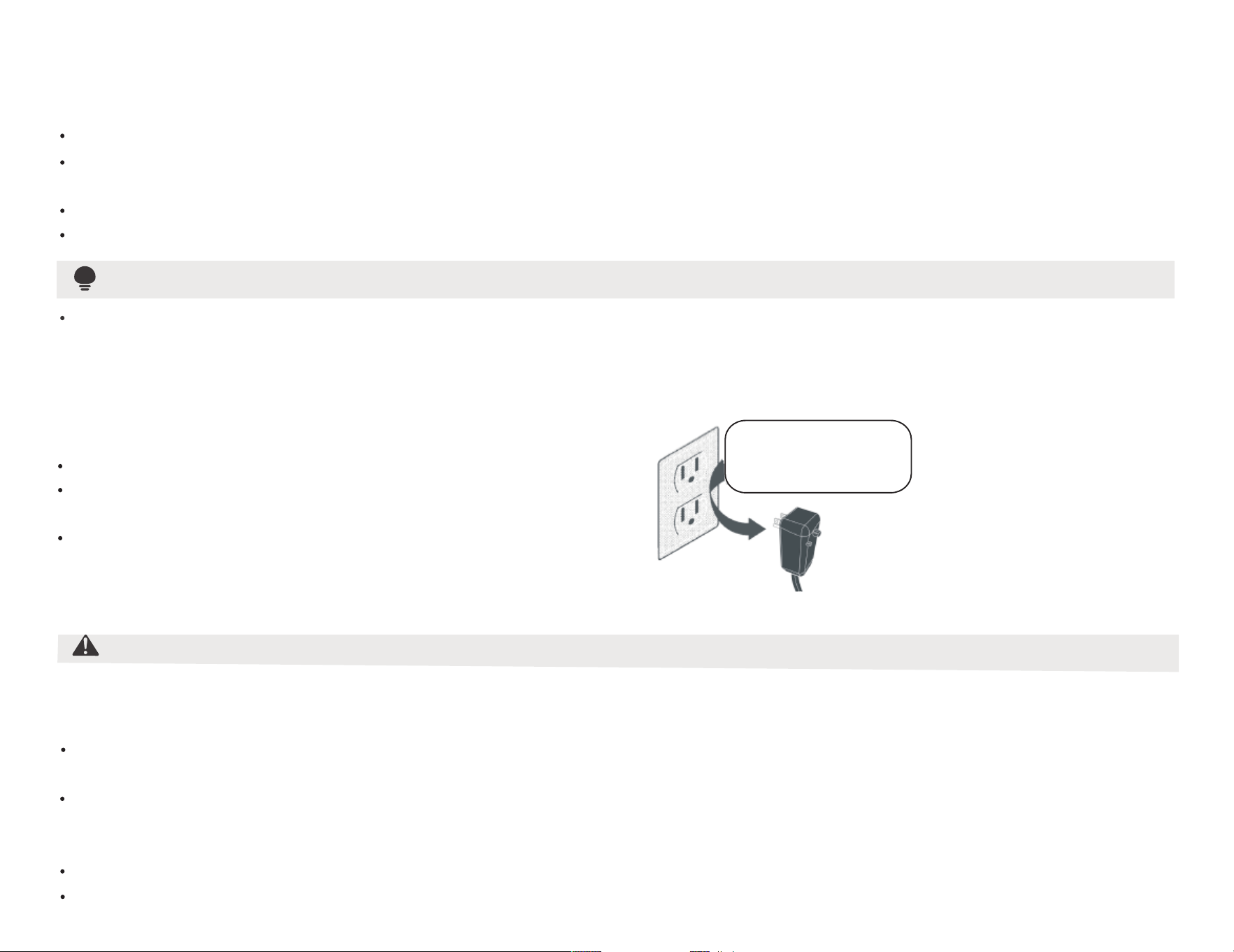
/3
(
5/$B??3
#
$3?3
-
#
$
*
" )
#$!
&$9
+,
#1?D ),5%3?3&$
$B??3
5%"B??3&$$,
#"’&$ ),A
-&
,
"
"! "*
(
),""2
,
-
#$,$$$-B
"$)$-
5$"!$,$&"
#$),"",$,$-
"$%
6""/&
$)-5$-
-('$"
-
)"+
-

/4
-E$
0"
!$&,$
&
&9
5$$$
$,(
$$*$F
&
&
5$4
(
-#
&"
$,-
G$,$--
-,
&+
9
55-31?BG5#.?B3H33B55.#G#?(3B.I?H1?(J+#5K?*(H!?L#5#.M?-353.H-!B.-(.!5#?1N3OM?-
B?M5BI?9 $2,"
,2-#,2
,$,-#,2
)")$
,
"
&
-.%
"
/+
! +
L/AC L/L1/L-IN
N/AC N/L2/N-IN

#0-
-
,@"A
-,),
#2,
$)-
#*"
$,-
7"-
"#%
/5
0
3
6
4
5
2
1
7
8
0/ 00 01
04
02
03
05
06
07
08
P)1@9Q<8:Q9;QA
P)1@9Q998>Q9;QA
+$’AR>
’6.7 w0,0.7 w06 (
+8’AR;
’3,0.1 w2,0.1 w0,0.1 (
P)1@9Q<8:Q>=QA
P)2@9Q998>Q>=QA
$)1@98:Q;98>Q9;98>QA
P)1@9Q<8;Q9;QA
0
2
1
4
3
6
5
7
0/
00
01
02
03
04
05
06
07
08
8
(@()1
(’()1
M,’",(
K
K$@98:Q;98>Q9;98>QA
R;R;
G’$()3
7"
B"
!"
#
$ % &
1&
+/R9@9Q998>Q:;QA

/6
&""'
21%" """."'
#9 13 &03
,07 @A.
),
&)$,
"
(
#
5/
# *
'
-
-"&
(
#%
E,
$-
)&
14,0.1
15
14,6.7
16
14,2.3
15,2.3
16
04,0.3
04,4.7
05,0.1
05,2.3
05,6.7
04,2.3
05,2.3
05 *06,0.1
11
04
08,2.3
05,2.3
07,4.7
06,0.7
12
05.06,0.1
11
06,0.7
12
05,2.3
08,2.3
07,4.7
04
05,2.3
$%+ 3 )
Vghsd,Vdrshmfgntrd
EqhfhcYhqd
Eqhdcqhbg
’456
’476
FdmdqYk Dkdbsqhb.
Gnsonhms
Vghqkonnk
RdYqr.Jdmlnqd
Edccdqr.Dldqrnm
Dldqrnm.Edccdqr
+ )Htnd
Dldqrnm"0
"1
"2
"3
"4
"5
"6
"7
"8
Edccdqr
Edccdqr.
Eqhdcqhbg
Vghsd,Vdrshmfgntrd.
EqhfhcYhqd.
(@=>7A
Vghsd,Vdrshmfgntrd.
EqhfhcYhqd
FdmdqYk Dkdbsqhb.
Gnsonhms
RdYqr.
(@=9A
Vghqkonnk
Vghqkonnk
8
-$
!
40bl
’1/ (
!
40bl
’1/ (
!01&1
" 50 ’3,02.05
"5,4.05 (
!$*
)
&
*$
05,2.7
05,2.7
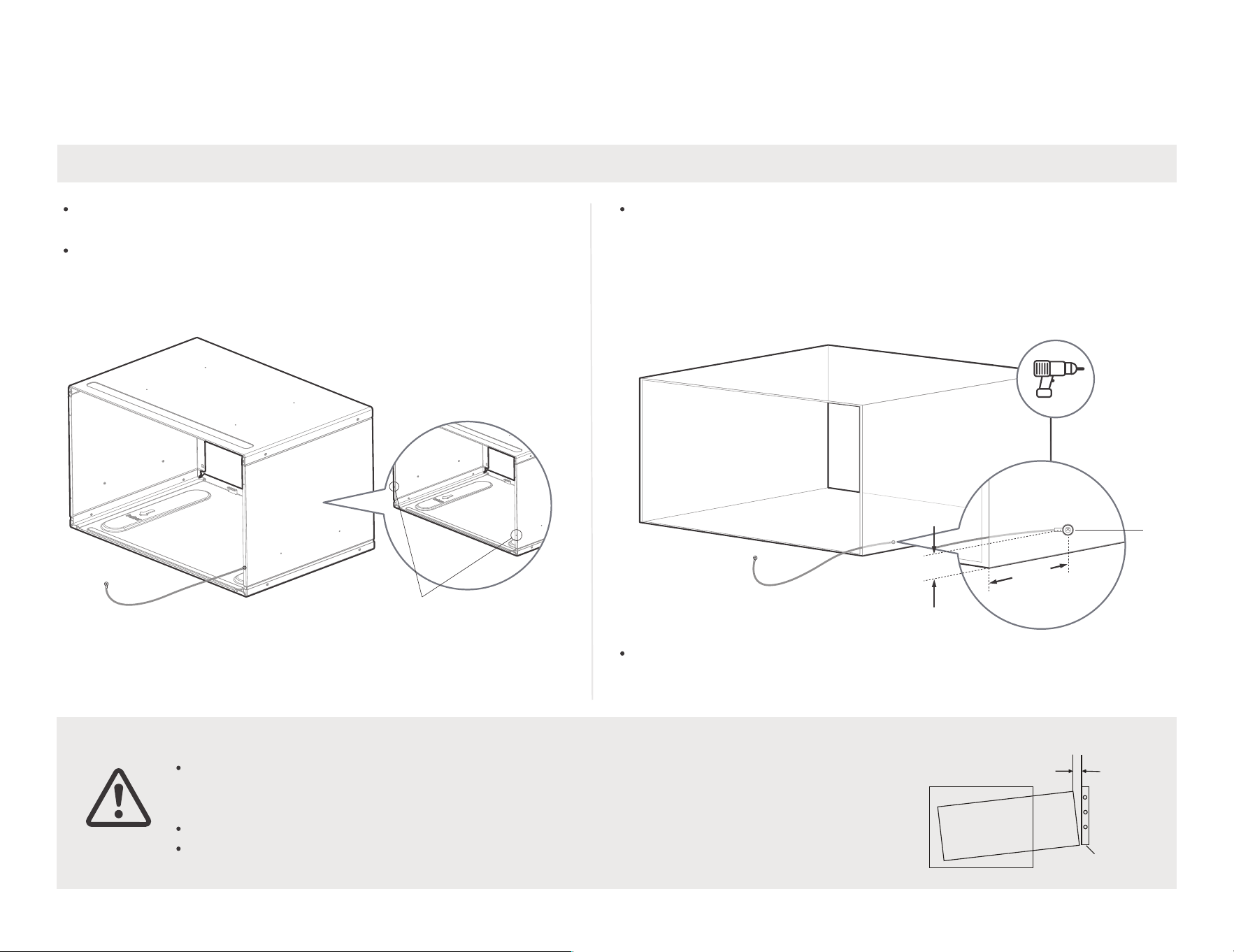
" 1"."' )&
/7
8
3,
$),&
$
#$*1H.3$-
-$)
5<,3”
5
-
5
TMHS
M,
1"."91"*
B,,
@(--%@/A
*%0.7
")
@-07(*@-08(
"
"*"
"2"*
&’ :%+(
3
0.7
0
2 LYw
#, )
*"
,’(-
%)&0.
7"F,,&
"2 ,&"
-3),
,
())
$-
,F,
F"
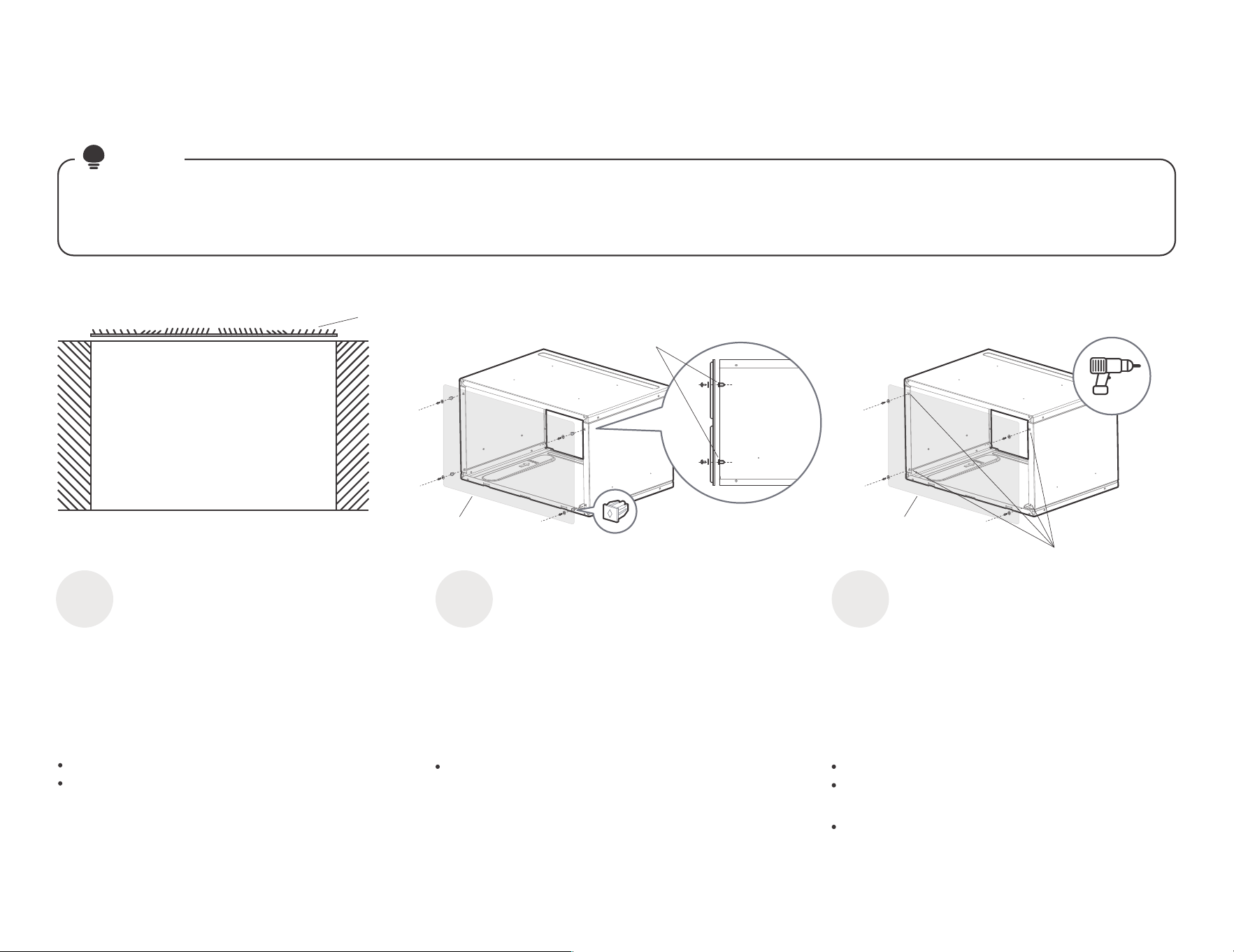
/8
-@(
$)
# $-
&%)&
%""'
B
!
,
M,
K
(F
(F
M$
!,
,0.7 -
7
7
;&".""6
2"
'
0
%""'
1
;&"."&6
%""'
2
1
5$
@-9SA
5
F
$
,
1
!
,
,0.7 -
(
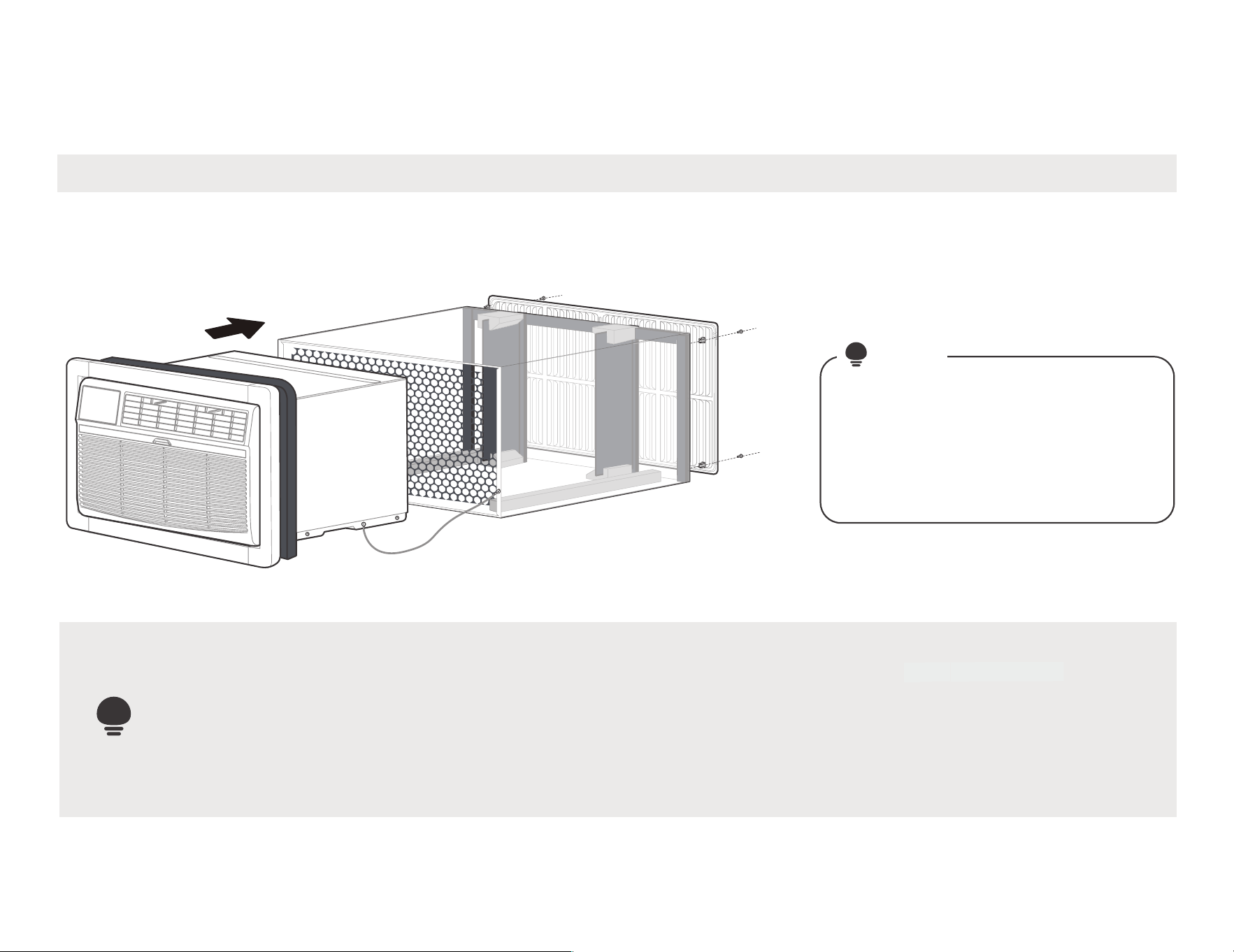
0/
1& '
:
#
#
*-
-
(
"8<.<%.%= "
HLONPS:MS
(
-B
#
#"
-,
&,
,@
"6
%A
#
,*
"1
/-
*#
6

0 1
1>22%
?'
#/
,)
'%$-
"*" @
"."% '
)
,*
,*$*
)@$
A
7
,*
"$)
-
"0"’04 )(
00
A
(@7(@8(-
A& "
1,P@-H9<A")
,T
(P@-H9>A"
,03 *
F,
,
(
@-HSA
F
-
(P@-H9;A"
03 *
F,
,
(
P@-H9<A"
,03 *
)
$-
(+
$
@-H:A"
03 *
,
&".
-
$@-HUA,
(
,

01
0 1
1>2
2%?
-
#/
,)
'%$-
"*" @
"."% '
)
,*
,*$*
)@$
A
7
,*
"$)
-
A
(@7(@8(-
A& "
(P@-H9>A"
,03 *
F,
,
(@
-HSA
F,-
(/@-H
9;A"
07 *
F
,
,-
(P@-H9
<A",
03 *)
$
-
(
$@-H:A
,
$@
(-
&".
-
$@-HUA,
1,P@-H9<A"
),T
06
3 (
Oqnsdbshnm
+$ 0
2.3
(
"1 ’08,2.3 )6
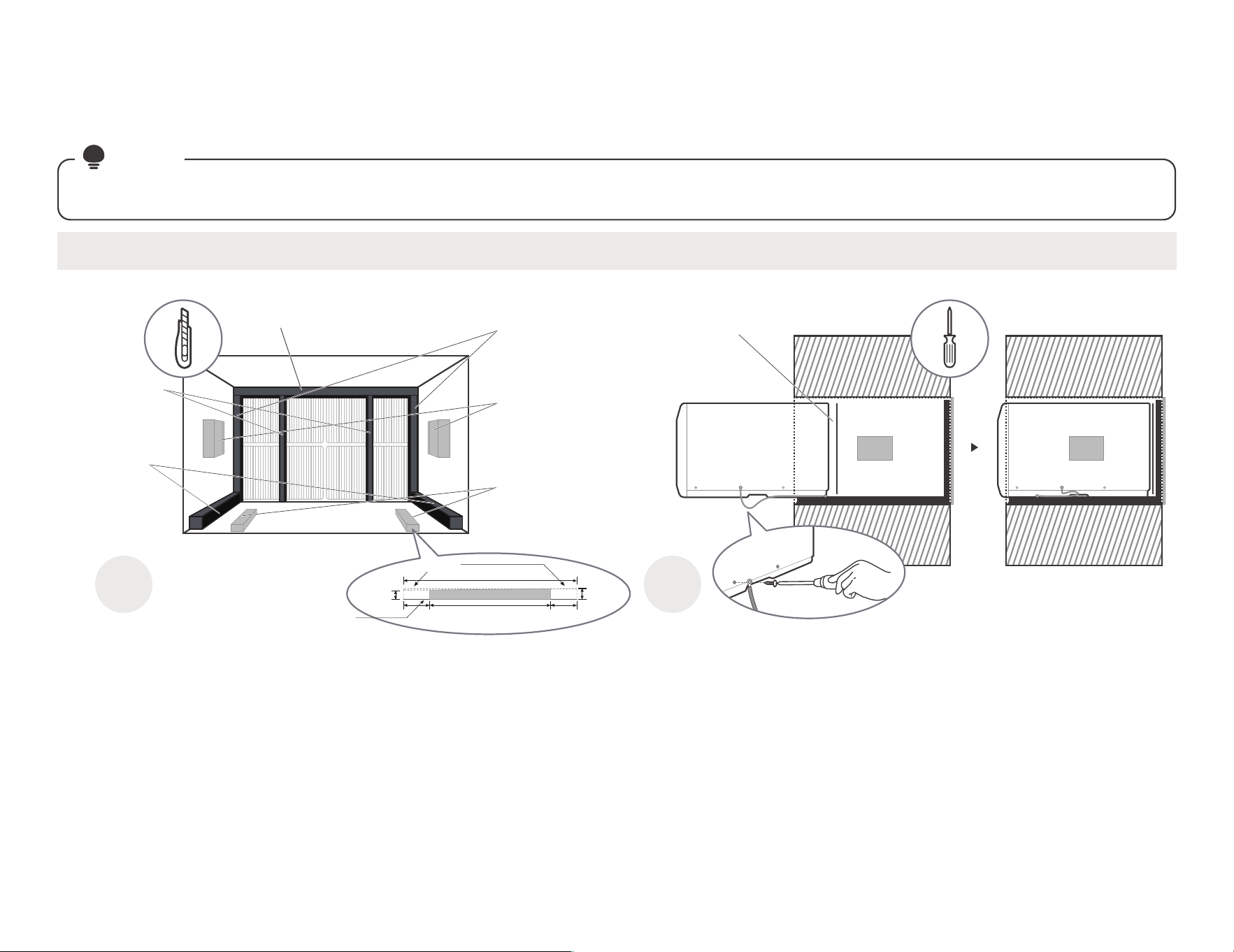
02
0 1
1>2
2%?
-
#/
,)
'%$-
"*" @
"."% '
)
,*
,*$*
)@$
A
7
,*
"$)
-
A
(@7(@8(-
A& "
(P@-H9>A"
,03 *
F,
,
(@
-HSA
F,-
(/@-H
9;A"
04 *
F
,
,-
(P@-H
9<A",
03 *)
$
-
(
$@-H:A&
,
$’
(-
&".
-
$@-HUA,
1,P@-H9<A"
),T
06
1,0.1 1 01,0.1
(
Oqnsdbshnm
0
2.3
+$
(
"2 . ’05,2.3 )6
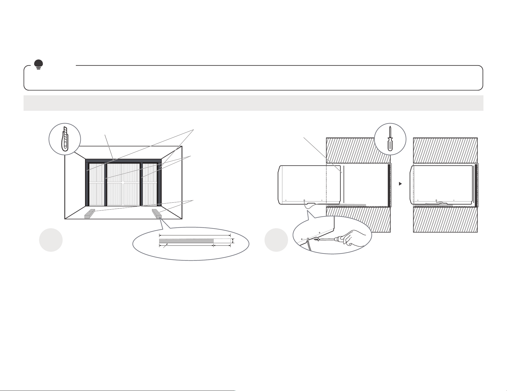
03
0 1
1>2
2%?
-
#/
,)
'%$-
"*" @
"."% '
)
,*
,*$*
)@$
A
7
,*
"$)
-
A
(@7(@8(-
A& "
(P@-H9>A"
,03 *
F,
,
(/@-H9<A"
,03 *)
$-
(
$@-H:A&
,
$’
(-
&".
-
$@-HUA,
1,P@-H9<A"
),T
06
3 02
(
Oqnsdbshnm
+$
0
2.3
P
(
"3 AB3 ’05,6.7 )6

04
0 1
1>2
2%?
-
#/
,)
'%$-
"*" @
"."% '
)
,*
,*$*
)@$
A
7
,*
"$)
-
A
(@7(@8(-
A& "
(/@-H9>A"
,04 *
F,
,
(/@-H9<A"
,04 *)
$
-
(
$@-H:A,
$@
(-
&".
-
$@-HUA,
1,P@-H9<A"
),T
(
"4 47 ’07,4.7 )6

05
A
(@7(@8(-
A& "
0 1
1>2
2%?
-
#/
,)
'%$-
"*" @
"."% '
)
,*
,*$*
)@$
A
7
,*
"$)
-
(/@-H9>A"
,04 *
F,
,
(/@-H9<A"
,04 *)
$-
(
$@-H:A&
,
$’
(-
&".
-
$@-HUA,
1,P@-H9<A"
),T
06
3
02
(
Oqnsdbshnm
$+
0
2.3
(
"5 <. ’06,0.7 )6

06
A
(@7(@8(-
A& "
0 1
1>2
2%
?-
#/
,)
'%$-
"*" @
"."% '
)
,*
,*$*
)@$
A
7
,*
"$)
-
(P@-H9>A",
04 *F,
,-
(P@-H9<A",
04 *,"
$-
(
$@-H:A,
$@
(-
-
$@-HUA,
1,P@-H9<
A"
,,T
-
!,
*
/8
@-6(1
$@-04(-
")
B?M5BI?.%"/$C
05,0.1
"
,
-
#
$
$
-
1-PF
9?6
"6
(
"6 <. ;5CD)(

07
0 1
1>22%
?'
#/
,)
'%$-
"*" @
"."% '
)
,*
,*$*
)@$
A
7
,*
"$)
-
A
(@7(@8(-
A& "
1,P@-H9<A"
),T
(P@-H9>A"
,03 *
F,
,
(P@-H9;A"
03 *
F,
,
(P@-H9
<A",
03 *)
$
-
&".
-
$@-HUA,
BYqqhdq 41E Rdqhdr’05.06,0.1 Oqnenmc(
"7 Vghsd Vdrshmfgntrd.EqhfhcYhqd.
(

08
A
(@7(@8(-
A& "
0 1
1>2
2%?
-
#/
,)
'%$-
"*" @
"."% '
)
,*
,*$*
)@$
A
7
,*
"$)
-
(/@-H9>A",
03 *F,
,-
(/@-H9<A",
03 *)
$-
(
$@-H:A,
$@
(-
1,P@-H9<
A"
,,T
-
!,
*
/8
@-6(1
$@-04(-
")
B?M5BI?.%"/$C
04,0.3
"
,-
#
$
$
-
-
$@-HUA,
1-PF
9?6
"6
(
"8 Vghsd Vdrshmfgntrd nt EqhfhcYhqd’11 Oqnenmc(
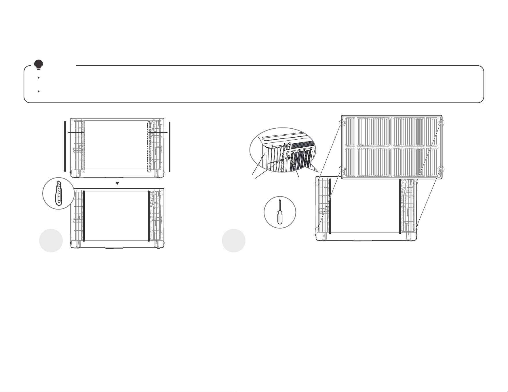
1/
A
#,#
-?& @A
# ,
0 1
1>;'756
""+-
(/@-H9>A$-.
1&%""
)1?"."'
5
$*)"
@-H9UA
#F
-
@-H9UA
(
/@-H9>A
30.7
Fqhkkd "
+
,*
$0.7 "
*)@
-H9UA7"
,,
?)&,
#& ,
(
&1%"" "'
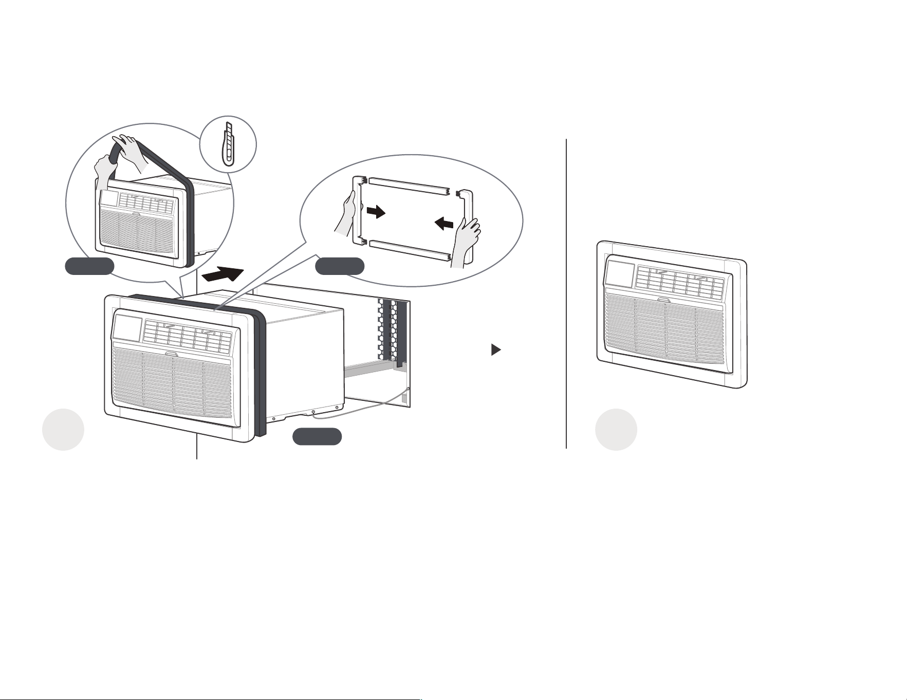
10
2=)&"+& '
A
0
&"+-
G 0 95
@-H>A
@-H<A&
"0
1
$?
"-
7&
)7?&"
'
G 19.#
,-
?
G 2 97&
/
,)
&"$)"
-
/ 1
/ 2
/ 0
K/@-HVA
B"

533?-3.H-9-
&
1*0&"'
:"
11
#
!
)
!
#F0
%"3
#
0,,&,
/
,"/$"$,
,7,
/$"$,
,,
>"
56,
1
K
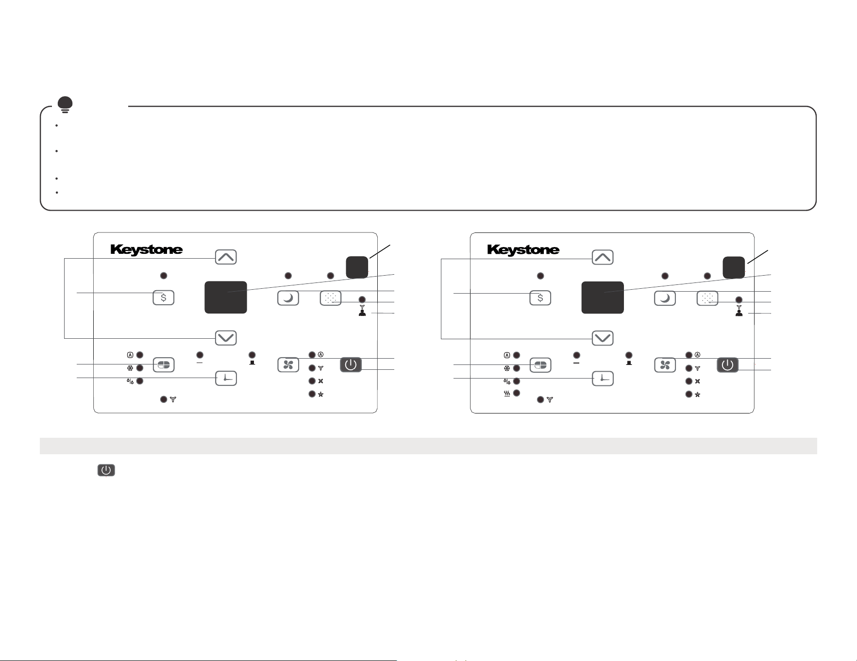
12
0-$$/E$$9
B?M5BI?9#$G7&&5@$575A
E&1)-
E
E$E/$(
5&$&
%$-# F-
(
(%$3-
#(W5775K?,*$
#$, *
&$$
5%
!HX?B
6
8
9
2
1
3
4
5
10
7
6
8
9
2
1
3
4
5
10
7
récepteur de
signaux à distance
récepteur de
signaux
à distance

13
EE$E/$(
1-3A$/A$AE/9
5% W53.+5,-
B?M5BI?9 5%W53+5/$"$,6,-(
$9SY(@U>Y7A<ZY(@:UY7A,$6,$*
7$
3-$9
@A@,*A>Y789Y(2/
%"
# "
- ()"
( 6 ,"
2/ -
#@A@,*A>Y789Y(
7- /$$EE 9
6- F? 9
5- /E/A 9
s'éteindra.
Le voyant s'allume après 250 heures de fonctionnement. Pour réinitialiser après le nettoyage du filtre, appuyez sur le bouton Vérifier le filtreet le voyant
Appuyez sur le bouton Check filter pour lancer la fonction. Cette fonction rappelle qu'il faut nettoyer le filtre à air pour un fonctionnementplus efficace.
4- E/E$8
/
$F"7
/(W5#?B??(&
!&
$&
$C5&7&M%G- (,$
5%
2- $E$9
5%1&
"&$,
#,>"9Z/$"$
53H75-A#< #<
5%,((HH#&1BN&53H@$53H(HH#.-K
-
6 &$$
"# 2 /$"$%"
"!&%#6,
( $"- #,"F
5(57A
-P#$G7&&5@$
5&7&&(,@$,*A#%"F
!,&%M,$&$$
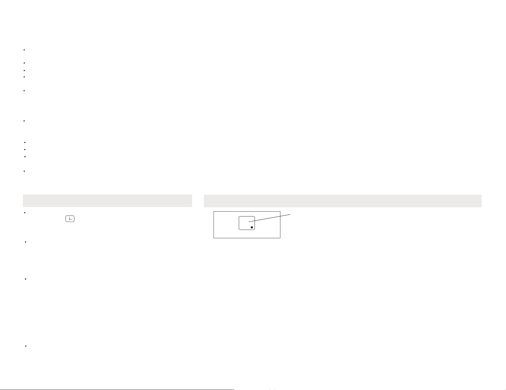
)"9
#$53H&$&,*’$
A&$$-
#F$$
)-1& /*$
"-
14
)"E9
(,7W+,,-
#$7* /%
)"3$
;"@)"+"69
(,(,,*W+,-
5%!* /-
)"+"9
$$,*@A-
!&6,6,*
?&/-
EE$E/$(
GR ,?,*$
,1,,
*
BR ,#
,1,
,,*
nR ,?
1,,
*
D2 ?1,
,
*
D/ 1??!BHM1
,,
*
0/-3A9
56,
&
1,,
7B ?
&
1,,
7B ?
9
&6,QW.QQ#HQ
?$&6,
$
56,QY(QQY7Q
$
1&,)- (*
)" 9
8- A8EE/A.G(9
,8 $
" Z&Z
5"/
$"6,
= &%
/$#
,/$" >; ,#F
,&/$" 9Z ,&
,5 Z&=
5%W53+5
$
($$
&%!BHKB5MM53?BH77
6,&%"
#$!BHKB5MM53?BH-
$
!BHKB5MM53?BH-.$$
,3&%
#$," &%

15
0
2
@.
" "# H".
OdqenqlYmbd Rnmnqd
"
3"
$
#-
%
H&%%
*
$*
H&"
[\]
"
A%BI"
#
UhaqYshnm
1
[$]-
%""
1
.
+&&1&-
M$'
&
F$
'-
#($2
( ,
,*,
/#
#F6,
7,,(
!"&%
38M
, &
2

16
""!.%&2'
!%
!%2*
#)" )
%#
)
–!)
,-
–#)"$
-B)
)
5$)
H&&
%)"
Mnsd9 -/,
";ZY(@9Z;Y7A%)"
-%/
)"
"%
5)
&
,$
-#
>;&;Q9;&:Q>&>Q
’
#W!
( -
212*") "
&!'
5,,
$,$
#
,*,,
,)
$B
%"
-/%&
,
",*
#
+,
–
–
–
–
!%"
9 -%$
- 1?&#. &
! &+.+'
533?-3.H-9 %,&
($

17
#@"
E/A
5&((
$
$"
" '
#,-?
#/,-B%"/
#,-5%B??3
#-5
$ &
"#
1)'
#"U>Y7@9SY(A#$U>Y7@9SY(A
#)",G
B
# ,527BH.1-
$"))
" @
.,%
)"##?
)"@
&)-
3"U;Y7@9:Y(A!&75-H-#N
#)" -%)B"?%!*75-H-#N
#,!&75-H-#N?&
-
#@" Rnktshnm
"
"
7",-%)"
3 ,B$

18
E& "
*
;+" "@
*6
#!"1/
#-B
#@"
Rnktshnm
#@"
"
)"=" @
.,
%)"
& @
):&-
H+
)
7",-%)""?-%
#,&"
#-!
#$*&&,1$-
!& *&H,,-7& *
#,5,E&&
+(&?-3.#53?B
,)
+%J$K?
/+
)'
#$,,(/,
@ )
35-
+%J$K?
/+
)'
..
B,,)
#)/")(
-3"/,&)
16120300A34513