
FORCE
®
KRAKEN TROLLING MOTOR
TRANSDUCER REPLACEMENT INSTRUCTIONS
Getting Started
WARNING
Always disconnect the trolling motor from the battery before performing any service.
Do not run the motor when the propeller is out of the water. Contact with the rotating propeller may result in
severe injury.
Do not run the motor when the propeller is out of the water. Contact with the rotating propeller may result in
severe injury.
CAUTION
When stowing or deploying the motor, be aware of the risk of entrapment or pinching from moving parts, which
can result in injury.
For the best possible performance and to avoid potential injury, damage to the device, or damage to your vessel,
installation by a qualified marine installer is recommended.
You should read these instructions completely before beginning this service, and make sure that you have the
tools and skill set needed to complete it. If necessary, you should use a qualified marine installer to ensure
proper service.
Tools Needed
• #2 Phillips screwdriver
• 2.5, 3, 4, 5, and 6mm hex bits or drivers
• Medium-strength thread-locking compound, such as LOCTITE
®
243
™
• Canned compressed air or an air compressor
• Diagonal pliers
• Zip ties
• Grommet wrench (included)
• Marine grease (included)
GUID-C553A4EB-6CD6-4D55-9D98-5246179CF642 v1August 2023
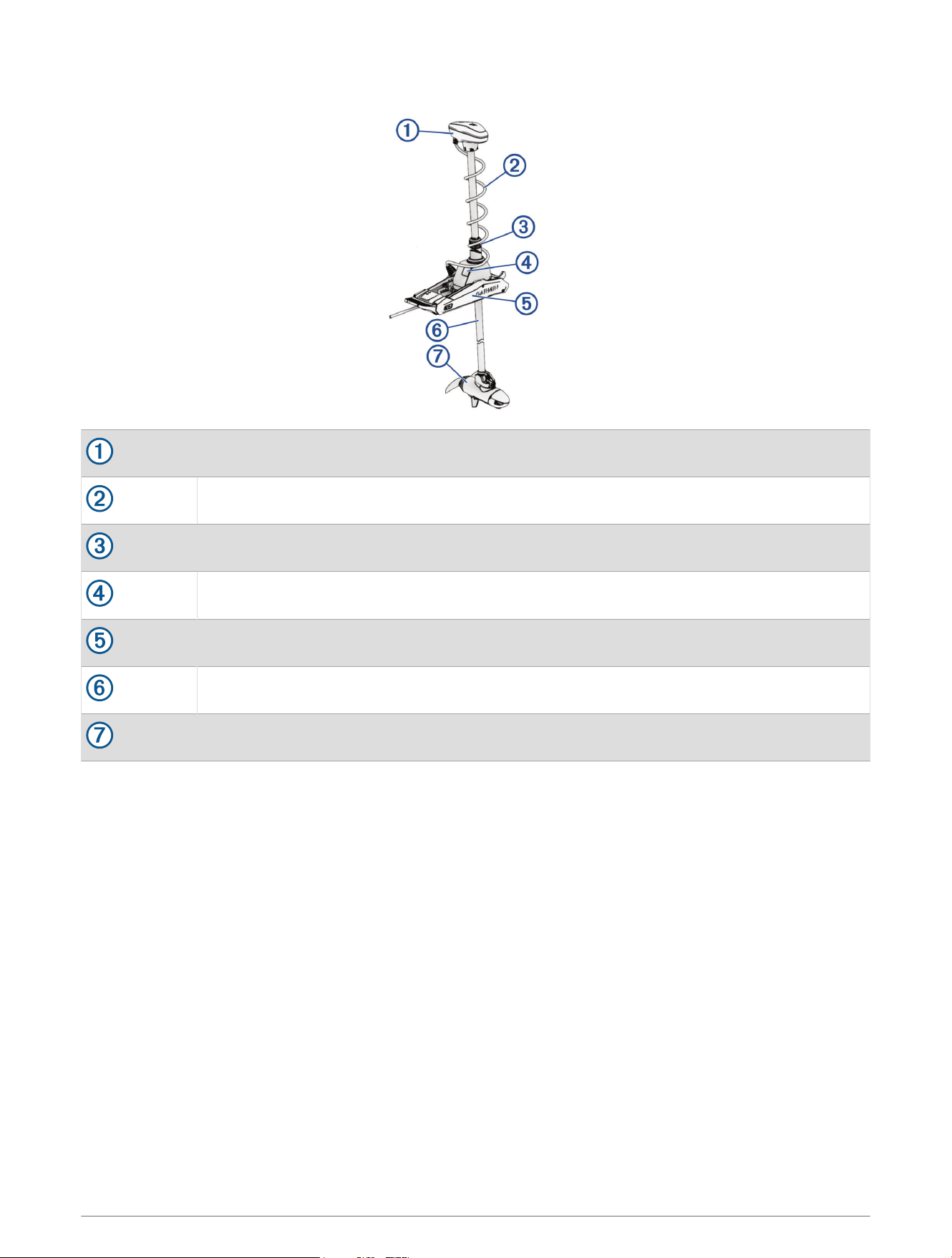
Device Overview
Shaft cap
Power and transducer cables
Depth-adjustment collar
Steering system
Mount
Shaft
Propeller drive motor
Preparing the Motor for Transducer Replacement
Before you can replace the transducer, you must perform these actions to prepare the motor.
1 Disconnect the motor from the power source.
2 Open the shaft cap (Opening the Shaft Cap, page3).
3 Disconnect the cables in and remove the shaft cap (Disconnecting the Cables in the Shaft Cap, page4).
4 Remove the propeller drive motor from the shaft (Removing the Propeller Drive Motor, page5).
2
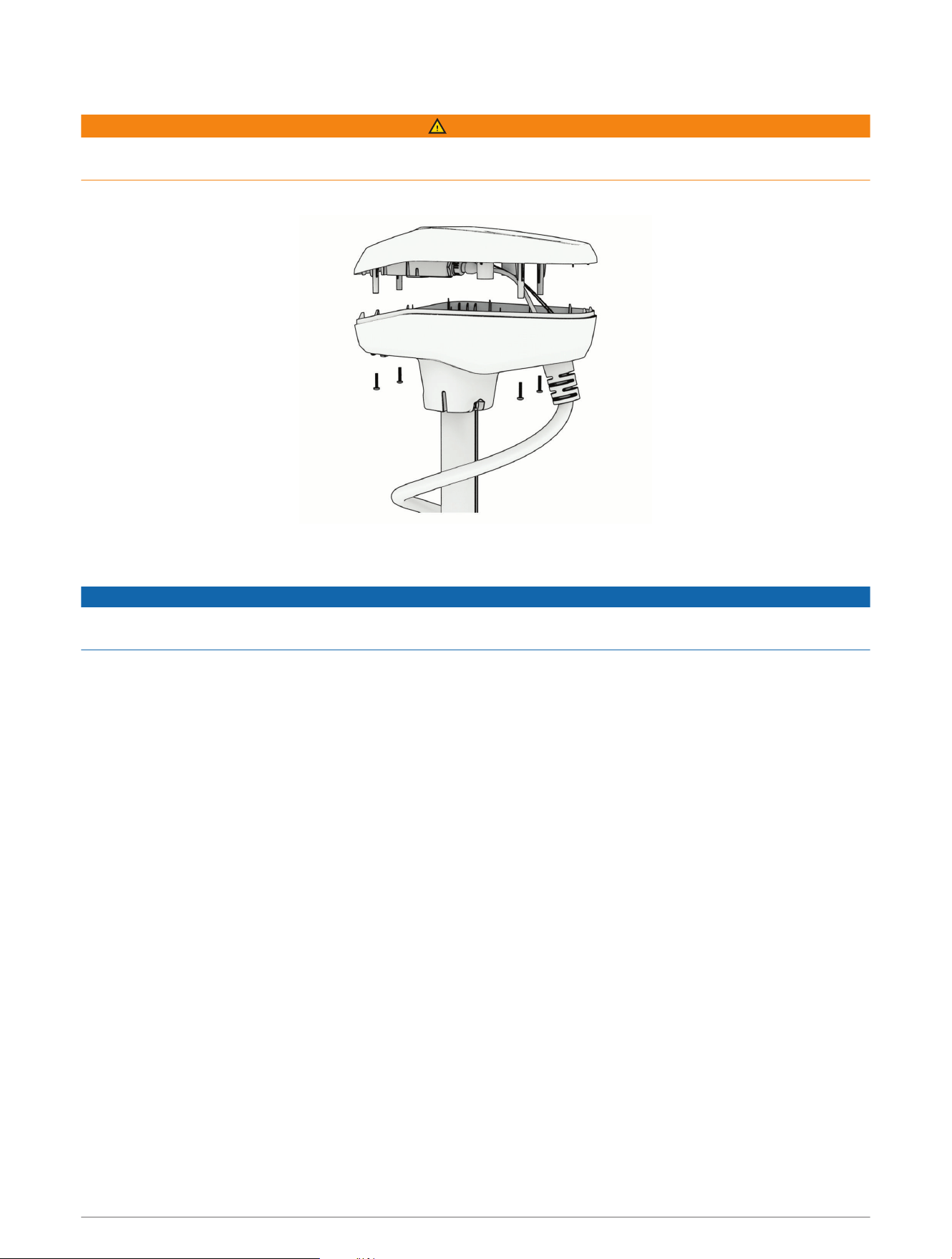
Opening the Shaft Cap
WARNING
Before you open the shaft cap, you must disconnect the motor from the power source. Failure to disconnect the
power source can lead to electrical shock or damage to the motor.
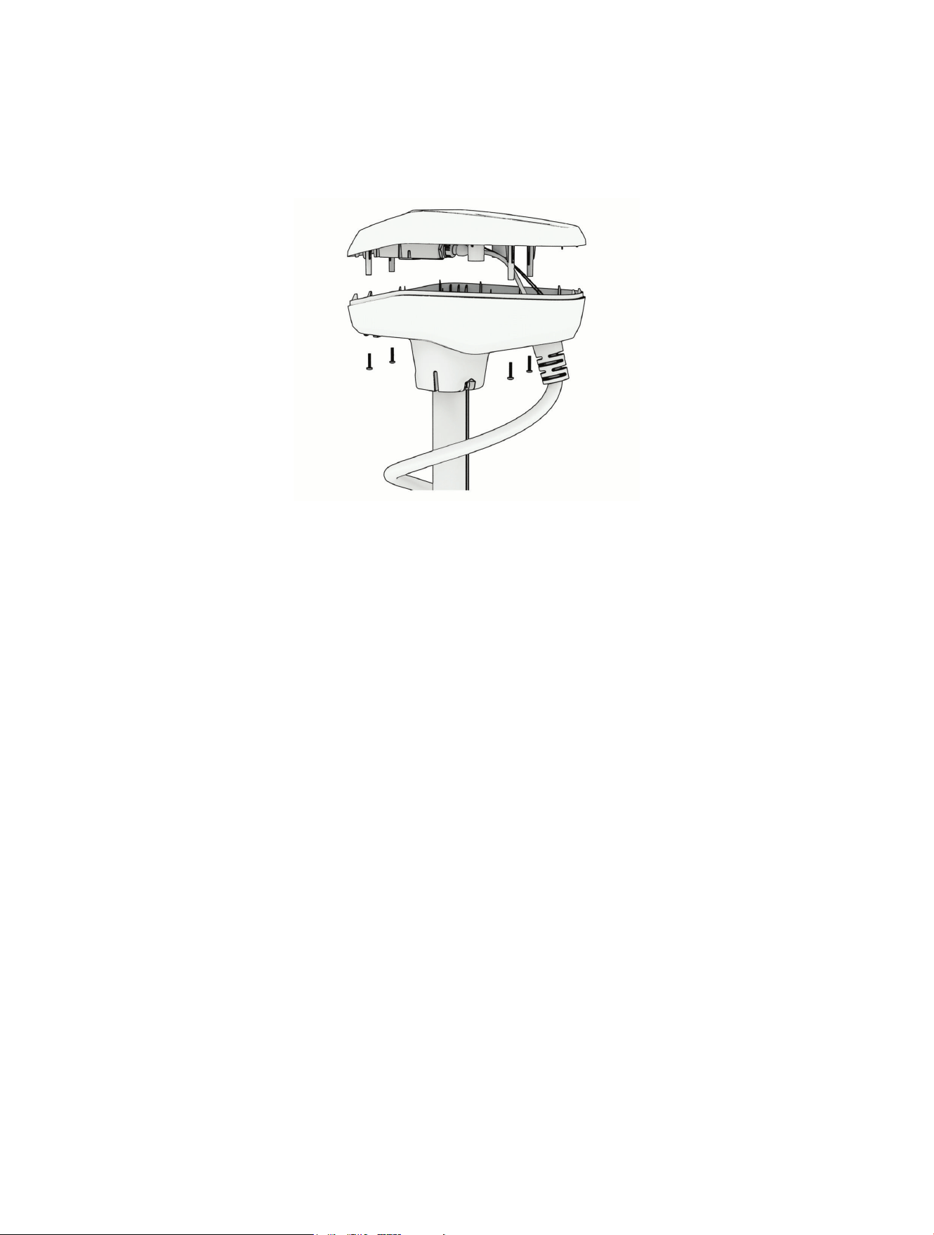
1 Using a #2 Phillips screwdriver, remove the four screws that secure the lid of the shaft cap.
You should place these screws in a safe place, because you must use them to close the shaft cap.
2 Carefully lift up the lid of the shaft cap to access the cable connectors inside.
NOTICE
There are two cables connected to the top of the shaft cap. Take care when opening the shaft cap to avoid
damaging the cables or connectors.
3
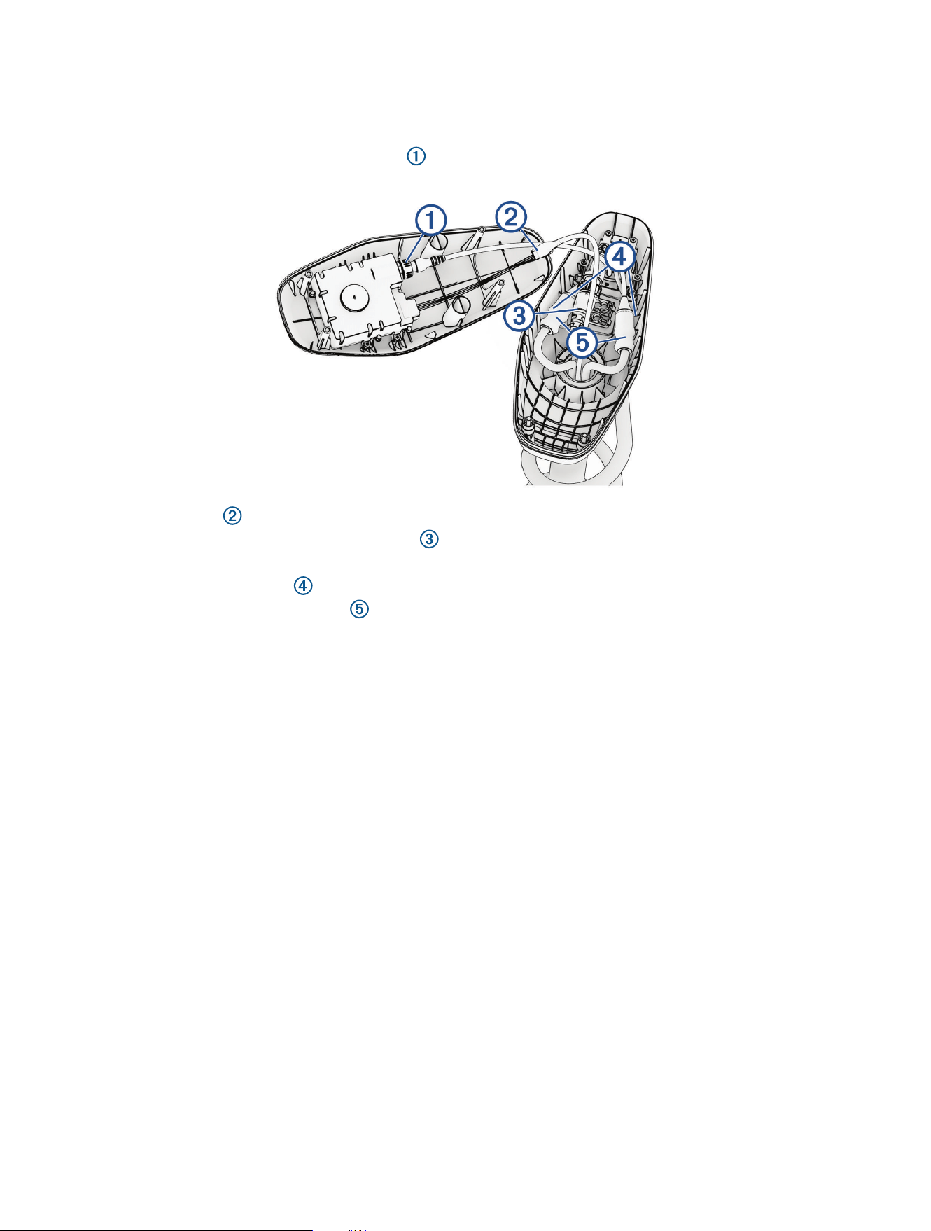
Disconnecting the Cables in the Shaft Cap
Before you can disconnect the cables in the shaft cap, you must open the shaft cap (Opening the Shaft Cap,
page3).
1 Unscrew and disconnect the USB connector .
Ensure the o-ring remains in place inside the connector.
2 Release the latch and pull the connectors apart to disconnect the data cable.
3 Unscrew and disconnect the transducer cable .
4 Carefully cut off the transducer cable locking ring.
5 Carefully cut off the zip ties .
6 Slide down the protective coverings on the power cables.
7 Using a 2.5 mm allen wrench, remove the four set screws on the two power cables.
8 Disconnect the power cables.
9 Remove the protective coverings from the power cables.
4
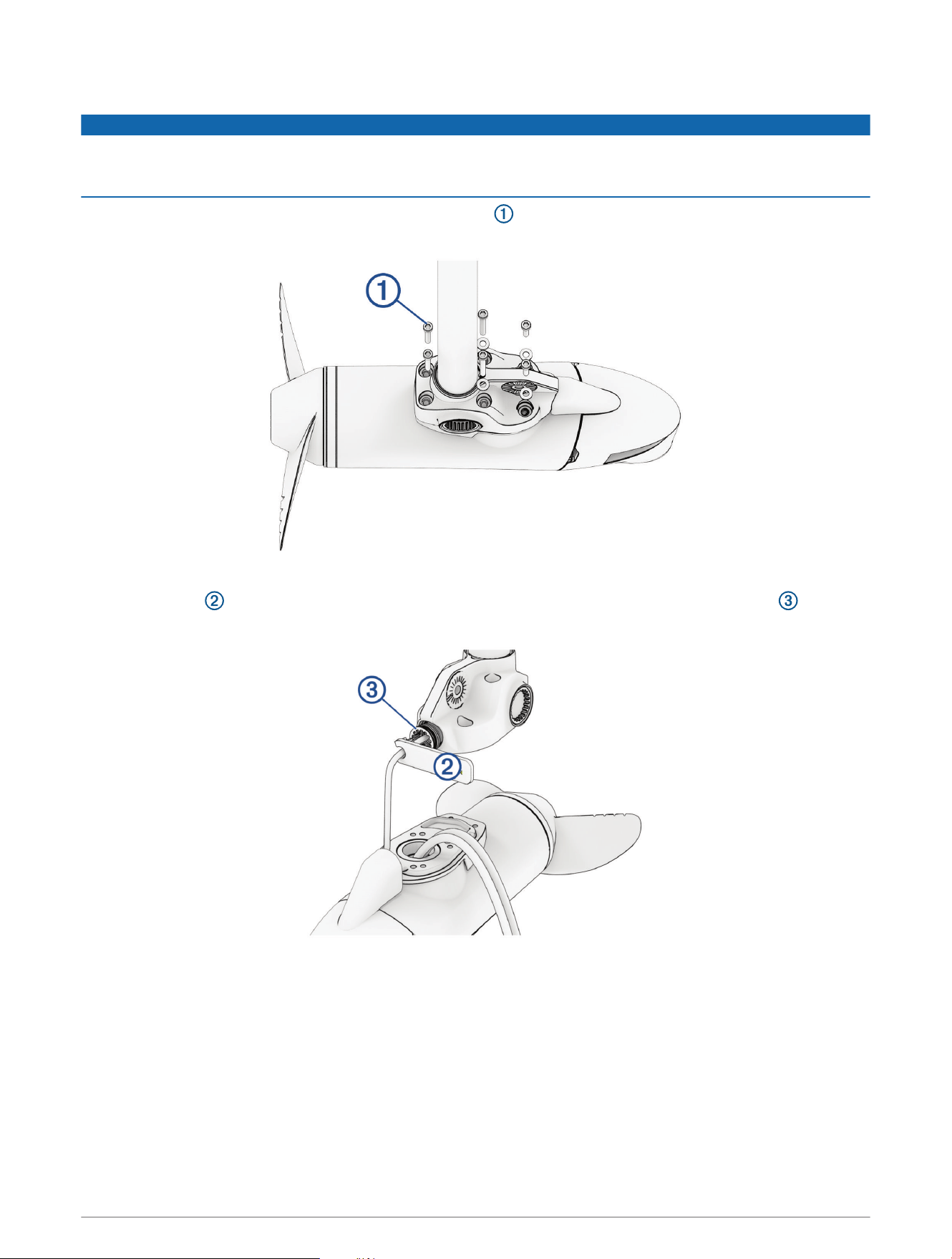
Removing the Propeller Drive Motor
NOTICE
When removing the propeller drive motor from the shaft, you must pull the cables themselves, and not the
motor. Pulling on the propeller drive motor may damage the cable connections inside the motor. The motor
should not be supported by the cables alone. Supporting the motor only with the cables may damage the motor.
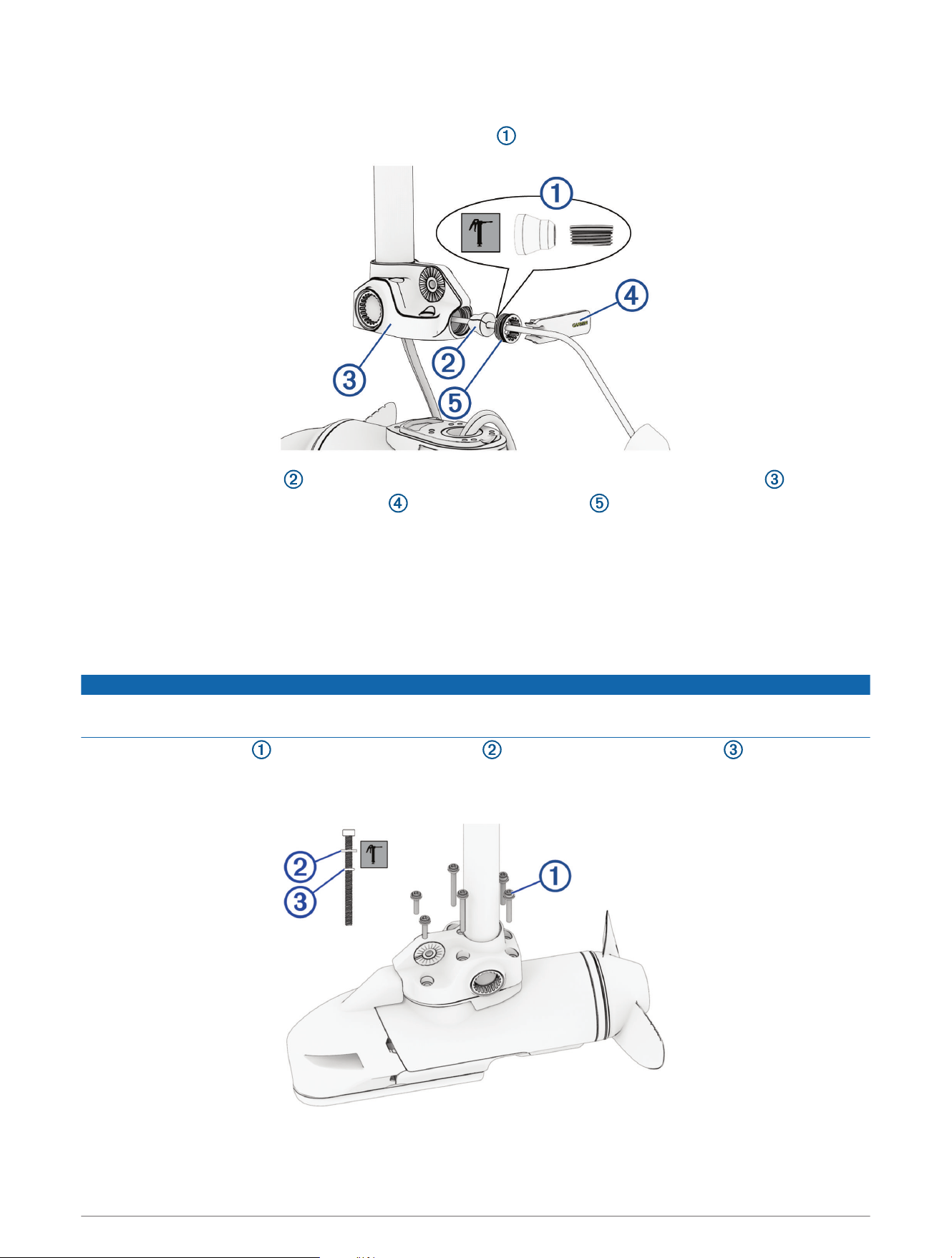
1 Using a 5mm hex bit or wrench, remove the six screws that secure the shaft base to the propeller drive
motor.
You should dispose of these six screws. New screws, washers, and o-rings are provided in the kit.
2 Using the tool included in the shaft and motor hardware service kit, remove the recessed nut that
secures the transducer cable to the shaft.
5
3 Straighten the cables at the top of the shaft, and slowly pull the propeller drive motor away from the shaft
base until you can see the power and data cables connected to the propeller drive motor.
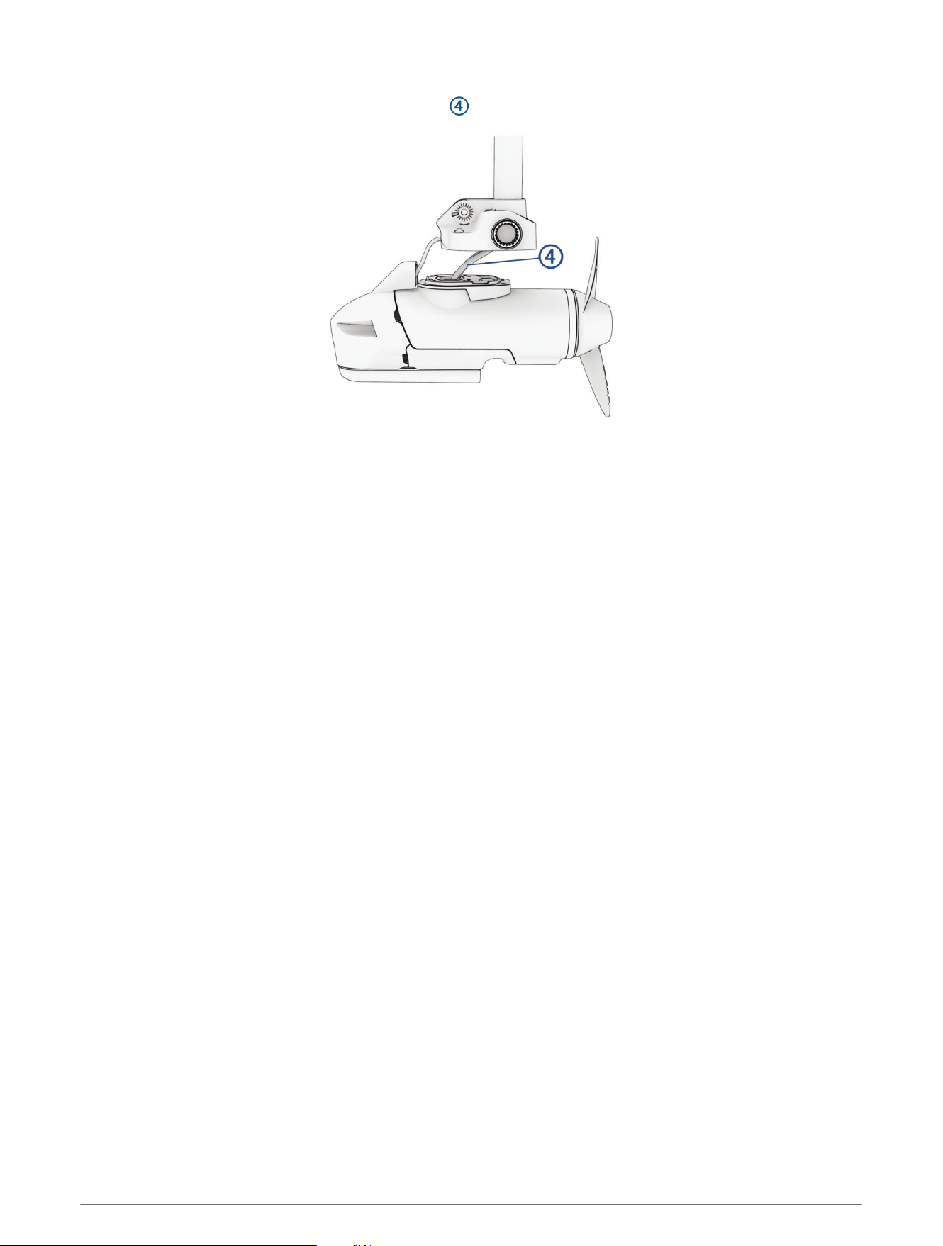
4 Push the transducer cable grommet out from inside the downshaft adapter.
5 Holding the cables only, slowly pull them through the shaft, taking care that the connectors do not get caught
on the top of the shaft.
The power and transducer cables should pull through the shaft completely.
Removing the Existing Transducer
After you prepare the motor by removing it from the downshaft adapter, perform these actions to remove the
existing transducer.
1 Remove the skeg and nose cone from the propeller drive motor (Removing the Skeg and Nose Cone,
page7).
2 Remove the transducer from the nose cone (Removing the Existing Transducer, page6) .
6
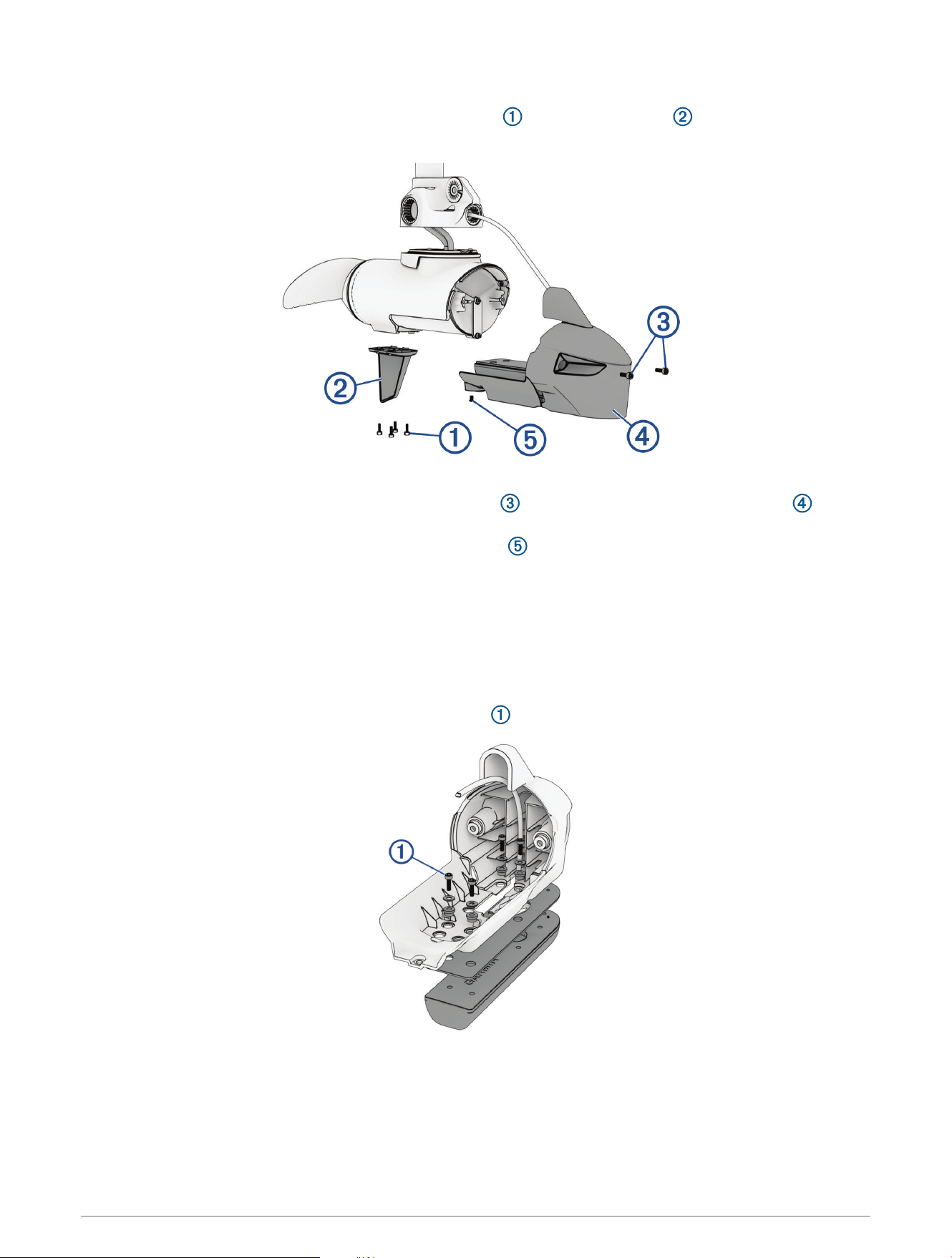
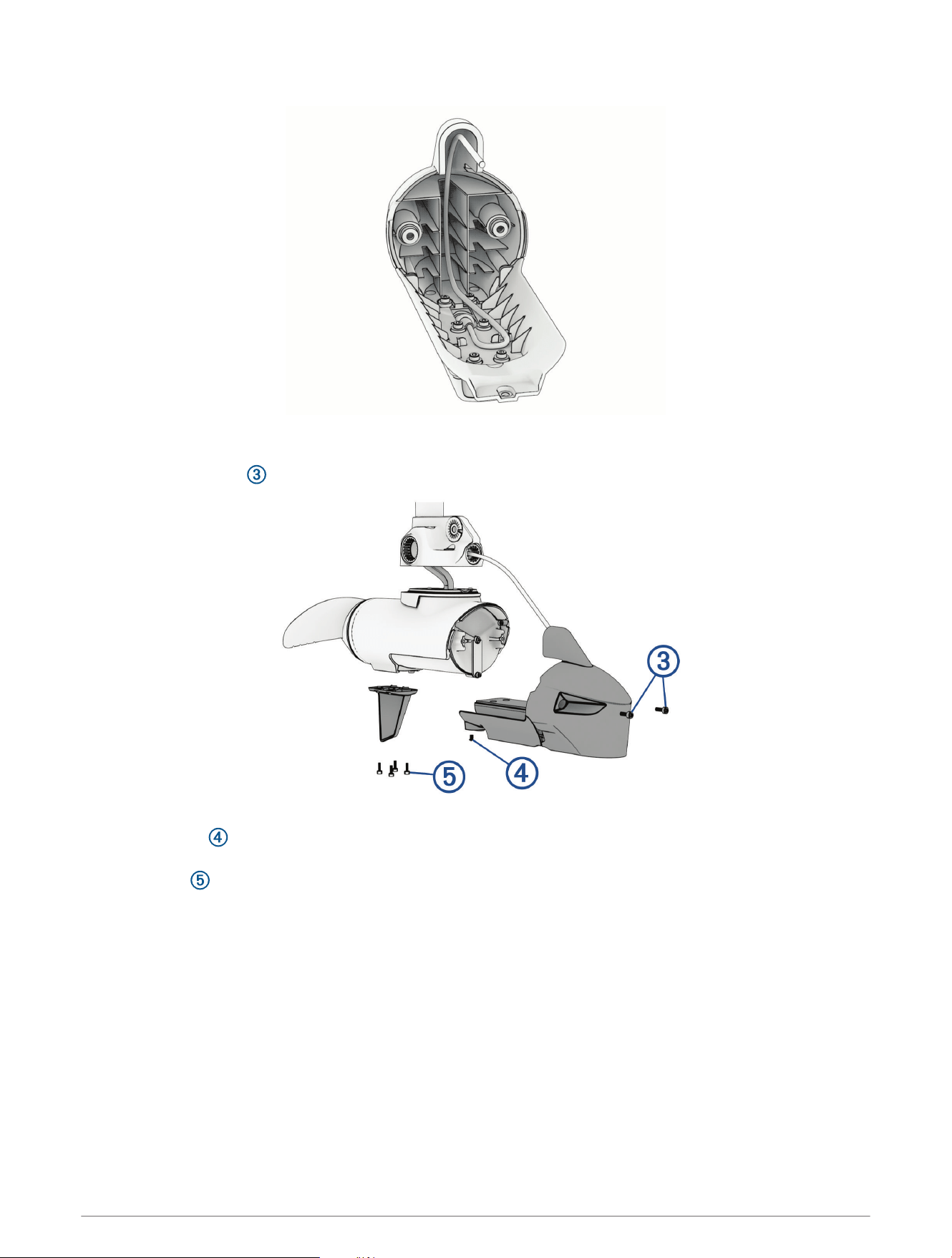
Removing the Skeg and Nose Cone
1 Using a 4mm hex bit or wrench, remove the four screws that secure the skeg to the propeller drive
motor.
2 Remove the skeg.
3 Using a 4mm hex bit or wrench, remove the two screws that secure the front of the nose cone to the
propeller drive motor.
4 Using a 3mm hex bit or wrench, remove the single screw that secures the bottom of the nose cone to the
propeller drive motor.
NOTE: You should keep all of these screws and parts in a safe place, because you must reinstall them when
reassembling the skeg and nose cone.
Removing the Transducer
Before you can remove the transducer, you must remove the nose cone (Removing the Skeg and Nose Cone,
page7).
1 Using a 3mm hex bit or driver, remove the four screws that secure the transducer to the nose cone.
When replacing the transducer, you should dispose of the four screws. New screws, washers, and bushings
are provided in the transducer replacement kit.
2 Remove the transducer and neoprene pad from the nose cone.
When replacing the transducer, you should dispose of the neoprene pad. A new pad is provided in the
transducer replacement kit.
7
Installing the Replacement Transducer
After you remove the existing transducer, perform these actions to install the replacement transducer.
1 Install the new transducer in the nose cone (Installing the Transducer, page9).
2 Install the nose cone and skeg on the propeller drive motor (Installing the Nose Cone and Skeg, page10).
3 Feed the cables through the shaft (Feeding the Cables Through the Shaft, page10).
4 Install the propeller drive motor on the shaft (Installing the Propeller Drive Motor, page12).
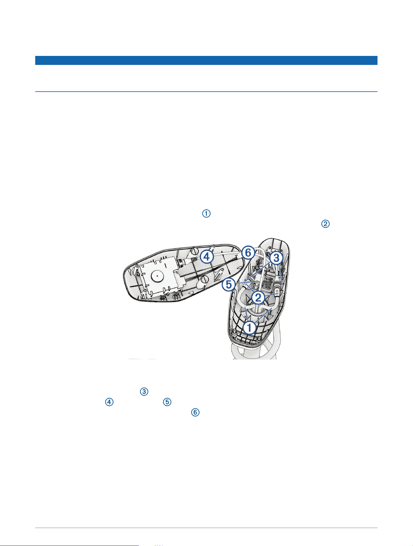
Replacing the Motor Gaskets
Before you can replace the motor gaskets, you must remove the propellor drive motor and pull all cables
completely through the shaft.
1 Remove and discard the blue motor gasket and black motor gasket .
2 Using the grease packet included in the kit, apply grease to the new blue and black motor gaskets included in
the kit and install them in place of the gaskets you removed.
8
Installing the Transducer
Before you can install the new transducer, you must remove the existing transducer (Removing the Existing
Transducer, page6).
NOTICE
New screws and seals are provided in the transducer replacement kit. You should use the new parts from the kit
instead of reusing the screws and seals you removed with the transducer.
1 Peel the paper backing off of the new neoprene pad from the transducer replacement kit and place it
sticky side down on the replacement transducer.
2 Using a 3mm hex bit or driver and the four new screws and bushings from the transducer replacement
kit, secure the replacement transducer to the nose cone.
3 Using the included grease packet, grease the 25mm (1in.) O-ring and place it on the recessed nut in the
transducer replacement kit.
9
Feeding the Cables Through the Shaft
1 Place the grommet nut over the transducer cable with the threaded side facing the downshaft adapter.
2 Feed the transducer cable a few feet into the shaft through the front hole of the downshaft adapter.
3 Bundle the power cables and feed them completely through the shaft with the transducer cable.
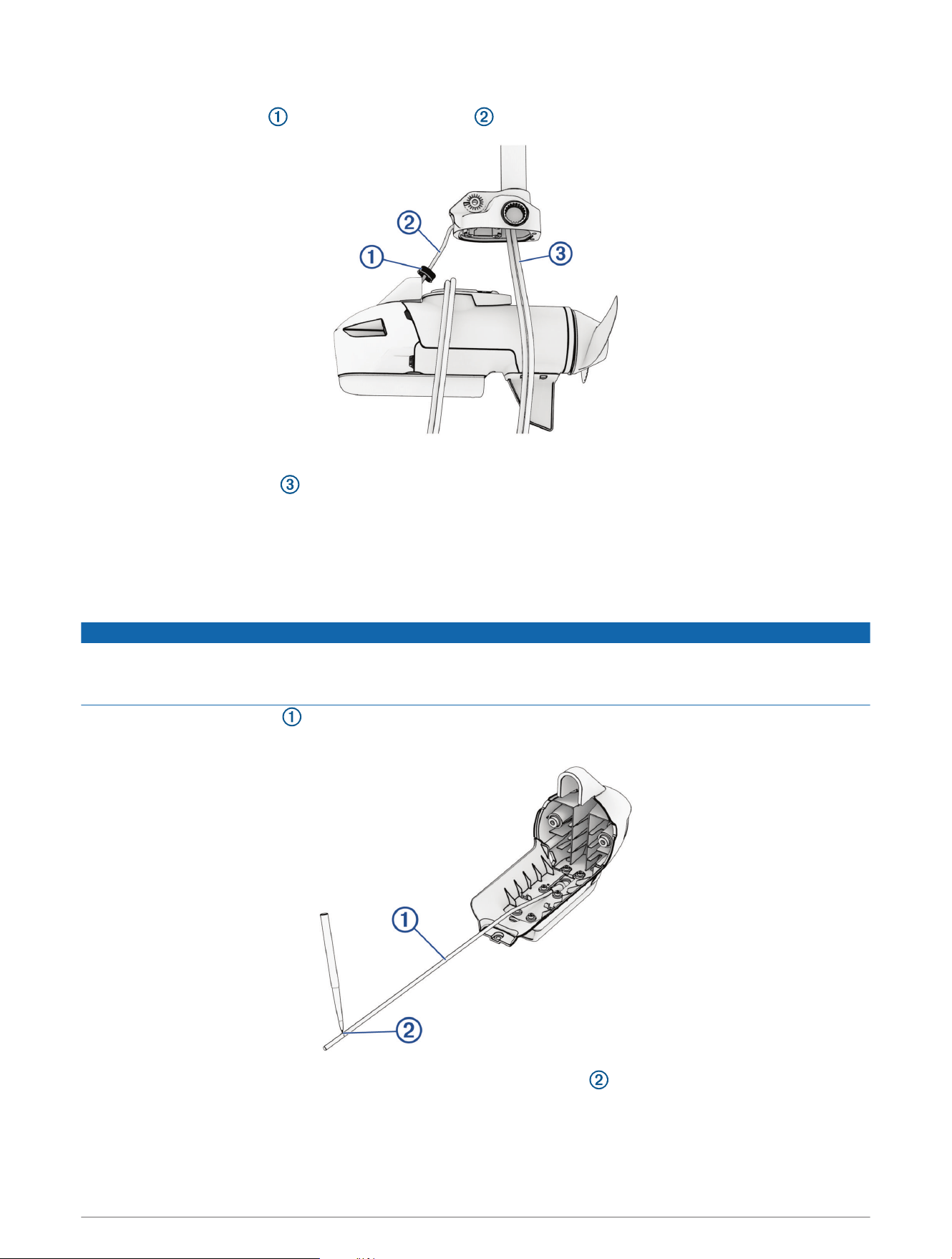
Installing the Nose Cone and Skeg
1 From the transducer replacement kit, select the cable grommet that fits your transducer cable:
• For a 4-pin transducer, select the cable grommet with the smaller hole.
• For an 8- or 12-pin transducer, select the cable grommet with the larger hole.
NOTICE
If you are not installing a transducer or are routing the transducer cable outside of the shaft, you must install the
provided grommet without a hole. Installing any of the other grommets without routing a transducer cable will
result in water ingress that may damage the motor.
2 Pull the transducer cable straight, and measure a 38cm (15in.) from the where the cable enters the
transducer.
3 Using a permanent marker, mark the measured location on the cable .
10
4 Route the transducer cable through the nose cone so it will fit correctly onto the propeller drive motor.
5 Place the nose cone onto the propeller drive motor.
6 Using a 4mm hex bit or wrench, secure the front of the nose cone to the propeller drive motor using the
existing two screws .
7 Using a 3mm hex bit or wrench, secure the bottom of the nose cone to the propeller drive motor using the
existing screw .
8 Using a 4mm hex bit or wrench, secure the skeg to the bottom of the propeller drive motor using the existing
four screws .
11
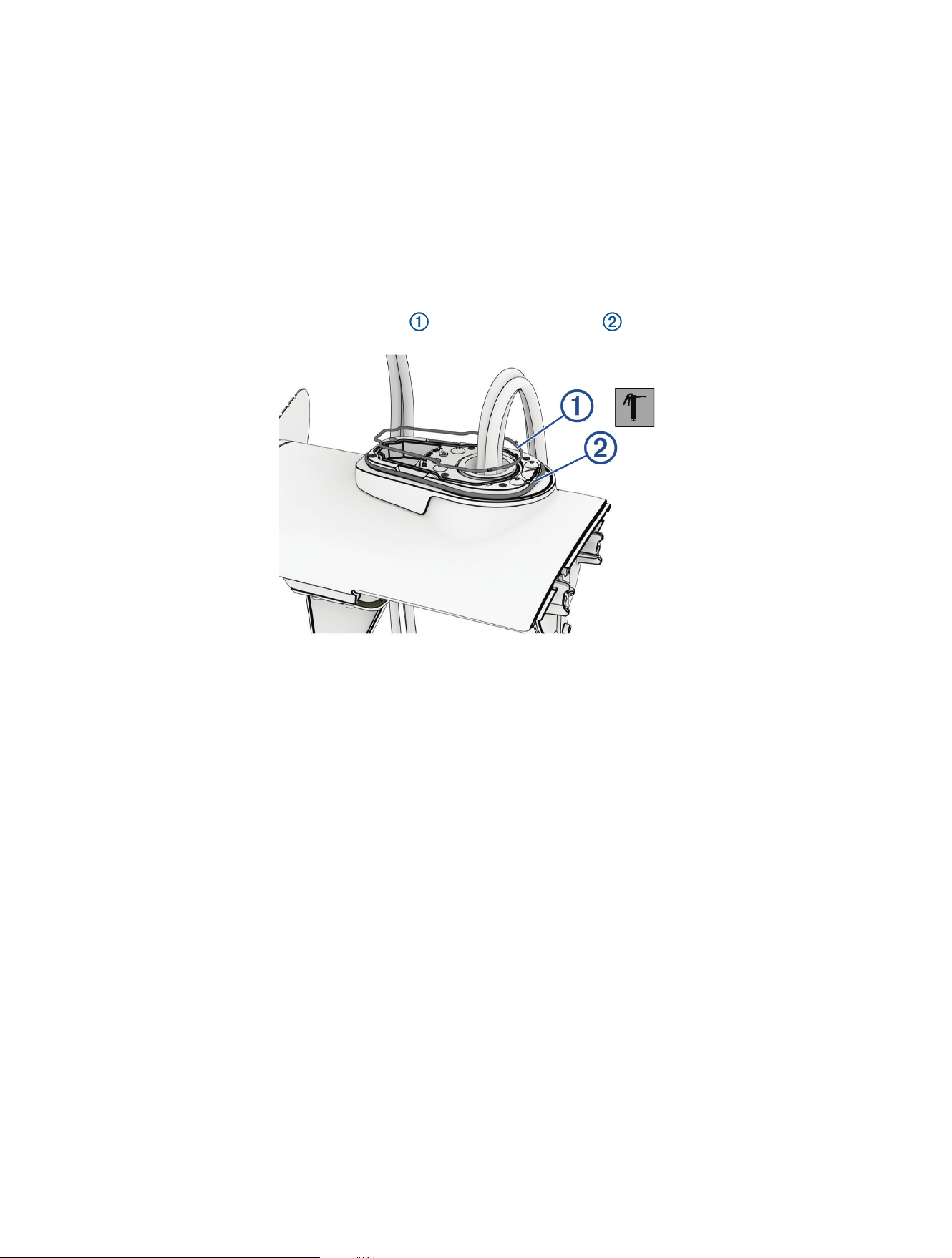
Installing the Grommets
1 Using the grease packet included in the kit, apply a thin film grease to the grommets and the section of the
transducer cable that feeds through the cable grommet .
2 Place the cable grommet over the transducer cable and slide it into the downshaft adapter .
3 Using the included grommet nut wrench , tighten the grommet nut .
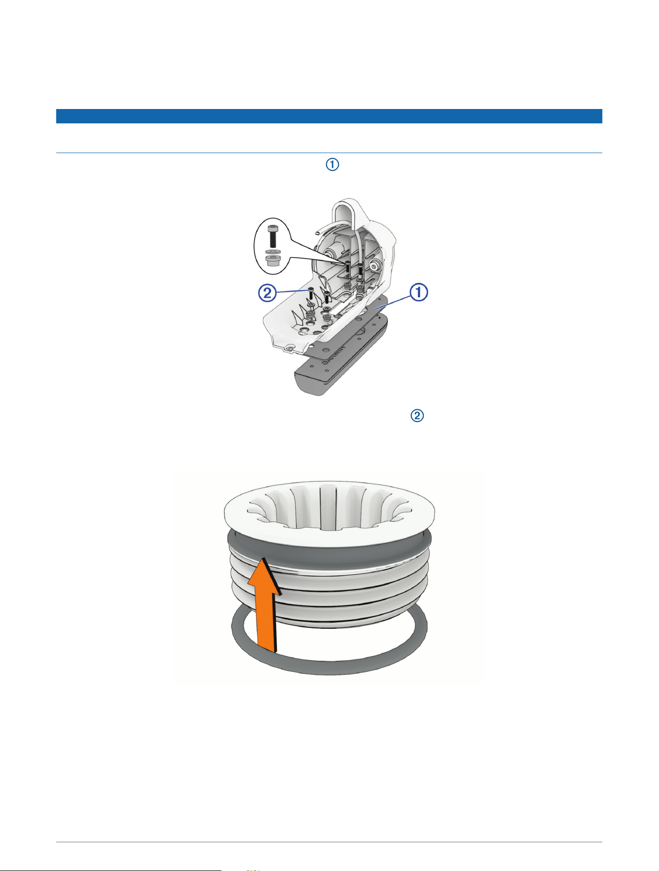
Installing the Propeller Drive Motor
Before you can install the propeller drive motor in the shaft, you must route the cables through the shaft
(Feeding the Cables Through the Shaft, page10).
1 Using canned compressed air or an air compressor, blow out any dirt or debris in the six threaded holes on
the top of the propeller drive motor.
2 Gently feed the cables the rest of the way through the shaft.
NOTICE
When feeding the cables, you must pull on the cable and not on the cable connectors. Pulling the cable
connectors may damage the connectors.
3 Prepare the six bolts in the kit by placing a washer and a 4.75mm (
3
/
16
in.) O-ring on each one.
NOTE: There are three different bolt lengths. Make sure the bolts are in the positions shown in the illustration
before tightening. The bolt length corresponds to the downshaft adapter height.
4 Using the grease packet included in the kit, apply grease to the 4.75mm (
3
/
16
in.) O-ring on each bolt.
Avoid getting grease on the bolt threads.
12
5 Apply a medium-strength thread-locking compound (not included) such as LOCTITE 243 to the threads in the
six threaded holes on the top of the propeller drive motor.
NOTICE
You must apply thread-locking compound in these holes to maintain a tight connection between the shaft base
and the propeller drive motor. Failure to use thread-locking compound can lead to water ingress and damage to
the motor.
6 Using a 5mm hex bit or wrench, thread all six of the prepared bolts approximately halfway to make sure that
the shaft base and the propeller drive motor are properly aligned and the gasket is in place.
7 With the shaft base and the propeller drive motor properly aligned, lightly tighten all six bolts by hand.
8 Using a torque wrench, tighten all six bolts to 4N-m (35lbf-in).
Completing the Trolling Motor Service
After you replace the transducer, you must perform these actions to complete the trolling motor service.
1 Connect the cables in the shaft cap (Connecting the Cables in the Shaft Cap, page13).
2 Close the shaft cap (Closing the Shaft Cap, page14).
3 Connect the motor to the power source.
Connecting the Cables in the Shaft Cap
1 Place the protective coverings on the power cables .
2 Reconnect the power cables and, using a 2.5 mm hex bit or wrench, tighten the set screws .
3 Slide the protective coverings over the power cable connections.
4 Secure the power cables to the shaft cap using zip ties at the locations you removed them when
disconnecting the power wires .
5 Reconnect the USB and transducer cable, and tighten the collars.
6 Align both sections of the data cable connector and press together to connect them.
13
Closing the Shaft Cap
Before you can close the shaft cap, you must connect the cables inside the shaft cap (Connecting the Cables in
the Shaft Cap, page13).
1 Place the lid on the shaft cap.
2 Using a #2 Phillips screwdriver, install the four screws to secure the lid of the shaft cap.
© 2023 Garmin Ltd. or its subsidiaries
Garmin
®
, the Garmin logo, and Force
®
are trademarks of Garmin Ltd. or its subsidiaries, registered in the USA and other countries. These trademarks may not be used
without the express permission of Garmin.
LOCTITE
®
is a trademark of Henkel Corporation in the U.S. and elsewhere.
© 2023 Garmin Ltd. or its subsidiaries
support.garmin.com