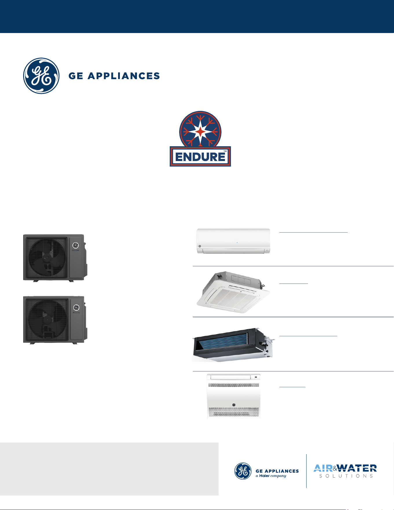
Single-Zone
Service Manual
Ductless Multi-Split Heat Pumps
Before troubleshooting or servicing equipment, review equipment
installation guides and conrm ALL installation requirements
& specications have been met. Including, but not limited to:
wiring, clearance, ducting (where applicable), power, and line set
requirements. Correct any installation issues before continuing.
Appearances vary by model
Outdoor Models
Appearances vary by model
Indoor Models
1G09ED2BEA
1G12ED2BEA
1G18ED2BEA
Wall Mount - Highwall
GS09WP2BEA
GS12WP2BEA
GS18WP2BEA
Cassette
US09CB2BEA
US12CB2BEA
US18CB2BEA
Mid-Static Ducted
US09MB2BEA
US12MB2BEA
US18MB2BEA
Console
US09FB2BEA
US12FB2BEA
US18FB2BEA
Model Lineup:

INTRODUCTION
2
ENGLISH
TABLE OF CONTENTS
Introduction ................................................................................................................. A1
Outdoor Units
...............................................................................................................B1
Highwalls
..................................................................................................................... C1
Cassettes
..................................................................................................................... D1
Console
.........................................................................................................................E1
Mid-Static Ducted
.........................................................................................................F1
Troubleshooting And Reference
................................................................................... G1
10-16-25: Edition release.

INTRODUCTION
A1
ENGLISH
INTRODUCTION
TABLE OF CONTENTS
SAFETY & PRECAUTIONS .......................................................................................................................................................A2
SPECIFICATIONS
....................................................................................................................................................................A3
Highwall Indoor ......................................................................................................................................................................A3
Cassette Indoor .....................................................................................................................................................................A4
Console Indoor .......................................................................................................................................................................A5
Ducted Indoor ........................................................................................................................................................................A6
FUNCTIONS AND CONTROL ..................................................................................................................................................A7
Cooling Operation Mode ........................................................................................................................................................A7
Heating Operation Mode .......................................................................................................................................................A8
Auto Mode ...............................................................................................................................................................................A9
Dry Mode .................................................................................................................................................................................A9
Defrost Operation ................................................................................................................................................................A10
Protection Functions ............................................................................................................................................................A10
Special Functions ..................................................................................................................................................................A11
INTRODUCTION
A2
ENGLISH
SAFETY & PRECAUTIONS
FOLLOW ALL WARNINGS, CAUTIONS, AND PRECAUTIONS BELOW, AND INDUSTRY BEST
SAFETY PRACTICES AND STANDARDS. FAILURE TO DO SO MAY RESULT IN EQUIPMENT
DAMAGE OR FAILURE, AND SERIOUS PERSONAL INJURY OR DEATH.
!
WARNINGS
Service should be performed by the dealer or another professional.
Improper service may cause water leakage, electrical shock, or re.
Use only the supplied or specied service parts.
Use of other parts may cause the unit to come lose, water leakage, electrical shock, or re.
The heat pump must be installed on a solid base that can support the unit’s weight.
An inadequate base or incomplete installation may cause injury in the event the unit falls o the base.
Electrical work should be carried out in accordance with the manual and national/local electrical wiring codes and rules of practice.
Insucient capacity or incomplete electrical work may cause electrical shock or re.
A dedicated power circuit must be used. The power supply should NEVER be shared by another appliance.
Wiring cable must be long enough to cover the entire distance with no splices.
Do not use an extension cord. Do not put other loads on the power supply, use a dedicated power circuit.
Failure to do so may cause abnormal heat, electric shock or re.
Only the specied wire types may be used for electrical connections between the indoor and outdoor units.
Firmly clamp the interconnecting wires so they receive no external stresses. Incomplete connections or clamping may cause terminal
overheating or re.
Wiring must not put undue stress or tension on the electrical covers or panels.
Install covers over the wires. Incomplete cover installation may cause terminal overheating, electrical shock, or re.
If any refrigerant has leaked out during service work, ventilate the room.
The refrigerant produces a toxic gas if exposed to ame.
After all service is complete, check for and repair any system refrigerant leaks.
The refrigerant produces a toxic gas if exposed to ames.
When servicing or relocating the system, keep the refrigerant circuit free from substances other than the specied refrigerant
(R454B), such as air or moisture
The presence of air or other foreign substance in the refrigerant circuit causes an abnormal pressure rise or rupture, resulting in injury.
During pump-down, stop the compressor before removing the refrigerant piping.
If the compressor is still running, and the stop valve is open during pump-down, air will be sucked into the system while the compressor
is running. This will cause abnormal pressure and noncondensables added to the system.
Unit must NOT be grounded to a utility pipe, arrester, or telephone line ground.
An complete ground may cause electrical shock, or re. A high surge current from lightning or other sources may cause damage to the
heat pump.
CAUTIONS
The heat pump must not be installed in a place where there is danger of exposure to ammable gas.
If the gas builds up around the unit, it may catch re.
Drain piping must comply with installation guidelines.
Inadequate piping may cause ooding.
Tighten are nuts according to the specied torque using a torque wrench.
If are nuts are overtightened, they may eventually crack and cause refrigerant leakage.
Ensure proper clearances around unit per installation guidelines.
INTRODUCTION
A3
ENGLISH
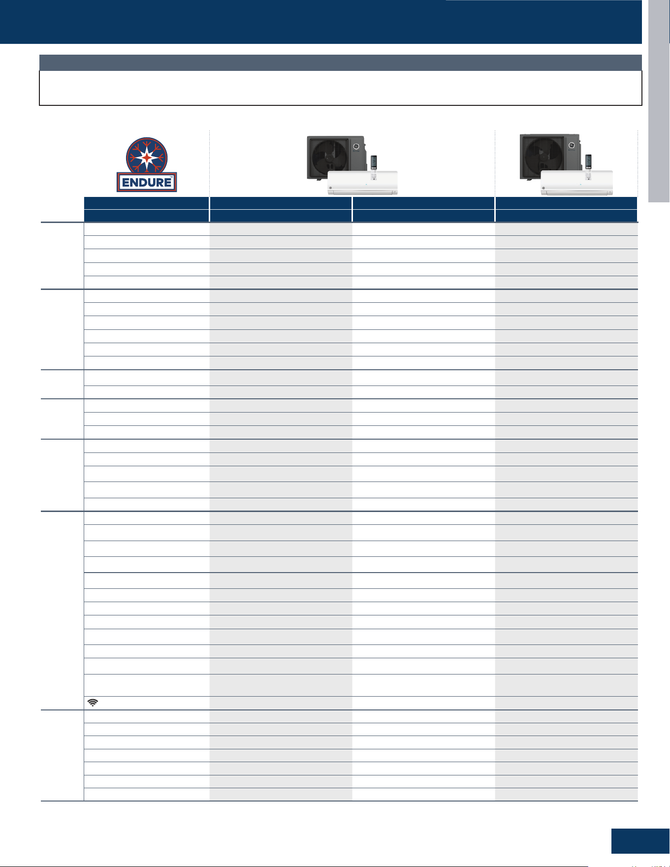
Outdoor Unit 1G09ED2BEA 1G12ED2BEA 1G18ED2BEA
Indoor Unit GS09WP2BEA GS12WP2BEA GS18WP2BEA
Cooling
Rated Capacity Btu/hr 9,000 12,000 17,000
Capacity Range Btu/hr 3,200-10,000 4,200-13,000 6,000-18,500
SEER2 27 25 20.5
EER2 12.5 12.5 12
Moisture Removal Pt./hr 2.30 3.80 4.80
Heating
Rated Heating Capacity 47°F Btu/hr 10,000 14,500 19,000
Heating Capacity Range Btu/hr 3,600-12,000 3,600-15,500 5,600-21,000
HSPF2 (IV) 11.0 11.0 10.0
Rated Heating Capacity 5°F Btu/hr 10,000 14,500 19,000
Heating Capacity at 5°F / Capacity at 47°F 100% 100% 100%
COP 5°F 1.8 1.8 1.8
Operating
Range
Cooling
(Without Wind Bae or Top Cover)
23~115°F (-5~46°C) 23~115°F (-5~46°C) 23~115°F (-5~46°C)
Heating -31~75°F (-35~24°C) -31~75°F (-35~24°C) -31~75°F (-35~24°C)
Power Supply
Voltage, Cycle, Phase (V/Hz/-) 208-230/60/1 208-230/60/1 208-230/60/1
Maximum Fuse Size A 20 20 30
Minimum Circuit Amp A 13 14 20
Outdoor Unit
Compressor Type DC Inverter Rotary DC Inverter Rotary DC Inverter Rotary
Outdoor Noise Level dB 54 55 60
Dimension: H x W x D in (mm)
25 1/4 x 35 3/8 x 12
(642 x 898 x 306)
25 1/4 x 35 3/8 x 12
(642 x 898 x 306)
27 3/4 x 38 3/8 x 13 3/8
(705 x 974 x 340)
Weight (Net/Ship) - lbs (kg)
83.41/96.87
(37.8/43.9)
88.15/100.4 (39.95/45.5) 104.59/122.46 (47.4/55.5)
Basepan Heater Yes Yes Yes
Indoor Unit
Fan Speed Stages 5 + Auto 5 + Auto 5 + Auto
Airow CFM: Cooling
(Turbo/High/Med/Low/Quiet)
395/355/310/260/170 410/370/280/210/170 580/530/480/400/350
Airow CFM: Heating
(Turbo/High/Med/Low/Quiet)
395/355/290/220/170 420/390/350/310/180 580/530/450/350/320
Indoor Sound Level dB: Cooling
(Turbo/High/Med/Low/Quiet)
44/42/36/32/27 46/44/38/32/25 51/50/44/37/25
Indoor Sound Level dB: Heating
(Turbo/High/Med/Low/Quiet)
43/41/37/32/29 43/42/39/36/25 49/47/40/35/26
Auto Up-Down Louver Ye s Yes Yes
Auto Left-Right Louver Ye s Yes
Yes
Drain Pipe Size O.D in 5/8 5/8 5/8
Dimension: H x W x D in (mm)
12 1/4 x 36 x 8 3/8
(312 x 914 x 213)
12 1/4 x 36 x 8 3/8
(312 x 914 x 213)
12 7/8 x 39 3/4 x 8 3/4
(327 x 1009 x 223)
Weight (Net/Ship) - lbs (kg) 24.49/30.56 (11.1/13.85) 24.49/30.56 (11.1/13.85) 29.57/36.63 (13.4/16.6)
Factory-Installed Refrigerant Detection
Sensor (RDS)
No No No
Refrigerant Detection Sensor (RDS)
Compatible
Yes
(UALS01A,
sold seperately)
Yes
(UALS01A,
sold separately)
Yes
(UALS01A,
sold separately)
WiFi*
Built-in Built-in Built-in
Refrigerant
Lines
Refrigerant R454B R454B R454B
Connections Flare Flare Flare
Liquid O.D. in 1/4 1/4 1/4
Suction O.D. in 3/8 3/8 1/2
Factory Charge Oz 46.6 50.1 58.6
Maximum Line Length Ft / m 66/20 66/20 83/25
Maximum Height Ft / m 33/10 33/10 50/15
SPECIFICATIONS
Our continued commitment to quality products may mean a change in specications without notice.
Visit GEAppliancesAirandWater.com to access current specication tables online.
NOTE
*WiFi includes SmartHQ
TM
Home and SmartHQ
TM
Service compatibility.
INTRODUCTION
A4
ENGLISH
Our continued commitment to quality products may mean a change in specications without notice.
Visit GEAppliancesAirandWater.com to access current specication tables online.
NOTE
Outdoor Unit 1G09ED2BEA 1G12ED2BEA 1G18ED2BEA
Indoor Unit US09CB2BEA US12CB2BEA US18CB2BEA
Panel (required, sold separately) QACCP01WA QACCP01WA QACCP01WA
Cooling
Rated Capacity Btu/hr 9,000 12,000 18,000
Capacity Range Btu/hr 3,000-10,000 3,000-13,000 6,000-19,000
SEER2 20 20 20
EER2 12 12 12
Moisture Removal Pt./hr 2.40 3.50 5.50
Heating
Rated Heating Capacity 47°F Btu/hr 10,000 12,500 18,000
Heating Capacity Range Btu/hr 3,000-11,000 3,000-14,000 6,000-19,500
HSPF2 (IV) 10.0 10.0 10.0
Rated Heating Capacity 5°F Btu/hr 9,000 10,000 14,400
Heating Capacity at 5°F / Capacity at 47°F 90% 80% 80%
COP 5°F 1.8 1.8 1.8
Operating
Range
Cooling
(Without Wind Bae or Top Cover)
23~115°F (-5~46°C) 23~115°F (-5~46°C) 23~115°F (-5~46°C)
Heating -31~75°F (-35~24°C) -31~75°F (-35~24°C) -31~75°F (-35~24°C)
Power Supply
Voltage, Cycle, Phase (V/Hz/-) 208-230/60/1 208-230/60/1 208-230/60/1
Maximum Fuse Size A 20 20 30
Minimum Circuit Amp A 13 14 20
Outdoor Unit
Compressor Type DC Inverter Rotary DC Inverter Rotary DC Inverter Rotary
Outdoor Noise Level dB 54 55 60
Dimension: H x W x D in (mm)
25 1/4 x 35 3/8 x 12
(642 x 898 x 306)
25 1/4 x 35 3/8 x 12
(642 x 898 x 306)
27 3/4 x 38 3/8 x 13 3/8
(705 x 974 x 340)
Weight (Net/Ship) - lbs (kg) 83.41/96.87 (37.8/43.9) 88.15/100.4 (39.95/45.5) 104.59/122.46 (47.4/55.5)
Basepan Heater Yes Yes Yes
Indoor Unit
Fan Speed Stages 5 + Auto 5 + Auto 5 + Auto
Airow CFM: Cooling
(Turbo/High/Med/Low/Quiet)
440/387/351/320/290 440/387/351/320/290 458/425/387/345/302
Airow CFM: Heating
(Turbo/High/Med/Low/Quiet)
440/387/351/320/290 440/387/351/320/290 479/441/387/345/302
Indoor Sound Level dB: Cooling
(Turbo/High/Med/Low/Quiet)
42/40/36/32/25 45/42/40/36/32 45/42/40/36/32
Indoor Sound Level dB: Heating
(Turbo/High/Med/Low/Quiet)
42/40/36/32/25 45/42/40/36/32 45/42/40/36/32
Auto Up-Down Louver Ye s Yes Yes
Auto Left-Right Louver No No No
Dimension: H x W x D in (mm)
10 1/4 x 22 3/4 x 22 3/4
(260 x 575 x 575)
10 1/4 x 22 3/4 x 22 3/4
(260 x 575 x 575)
10 1/4 x 22 3/4 x 22 3/4
(260 x 575 x 575)
Weight (Net/Ship) - lbs (kg) 32.41/47.4 (14.7/21.5) 32.41/47.4 (14.7/21.5) 32.41/47.4 (14.7/21.5)
Drain Pipe Size O.D in 1* 1* 1*
Condensate Pump Built-In Built-In Built-In
Max. Drain-Lift Height in (mm) 47 1/4 (1200) 47 1/4 (1200) 47 1/4 (1200)
Factory-Installed Refrigerant Detection Sensor
(RDS)
No No No
Refrigerant Detection Sensor (RDS) Compatible Yes (UALS01A, sold separately) Yes (UALS01A, sold separately) Yes (UALS01A, sold separately)
WiFi**
Built-in Built-in Built-in
Refrigerant
Lines
Refrigerant R454B R454B R454B
Connections Flare Flare Flare
Liquid O.D. in 1/4 1/4 1/4
Suction O.D. in 3/8 3/8 1/2
Factory Charge Oz 46.6 50.1 58.6
Maximum Line Length Ft / m 66/20 66/20 83/25
Maximum Height Ft / m 33/10 33/10 50/15
*Condensate drain adapter shipped with the indoor unit is designed to accept a 3/4” PVC pipe. **WiFi includes SmartHQ
TM
Home and SmartHQ
TM
Service compatibility.
SPECIFICATIONS
INTRODUCTION
A5
ENGLISH
SPECIFICATIONS
Our continued commitment to quality products may mean a change in specications without notice.
Visit GEAppliancesAirandWater.com to access current specication tables online.
NOTE
Outdoor Unit 1G09ED2BEA 1G12ED2BEA 1G18ED2BEA
Indoor Unit US09FB2BEA US12FB2BEA US18FB2BEA
Cooling
Rated Capacity Btu/hr 9,000 12,000 17,000
Capacity Range Btu/hr 3,000-10,000 3,000-13,500 6,000-18,500
SEER2 20 20 19
EER2 12 12 9
Moisture Removal Pt./hr 2.16 3.40 3.80
Heating
Rated Heating Capacity 47°F Btu/hr 10,000 12,300 18,000
Heating Capacity Range Btu/hr 2,500-10,000 2,500-13,000 6,000-19,000
HSPF2 (IV) 10.5 9.5 9.5
Rated Heating Capacity 5°F Btu/hr 9,000 10,000 14,400
Heating Capacity at 5°F / Capacity at 47°F 90% 81% 80%
COP 5°F 1.8 1.8 1.8
Operating
Range
Cooling
(Without Wind Bae or Top Cover)
23~115°F (-5~46°C) 23~115°F (-5~46°C) 23~115°F (-5~46°C)
Heating -31~75°F (-35~24°C) -31~75°F (-35~24°C) -31~75°F (-35~24°C)
Power Supply
Voltage, Cycle, Phase (V/Hz/-) 208-230/60/1 208-230/60/1 208-230/60/1
Maximum Fuse Size A 20 20 30
Minimum Circuit Amp A 13 14 20
Outdoor Unit
Compressor Type DC Inverter Rotary DC Inverter Rotary DC Inverter Rotary
Outdoor Noise Level dB 54 55 60
Dimension: H x W x D in (mm)
25 1/4 x 35 3/8 x 12
(642 x 898 x 306)
25 1/4 x 35 3/8 x 12
(642 x 898 x 306)
27 3/4 x 38 3/8 x 13 3/8
(705 x 974 x 340)
Weight (Net/Ship) - lbs (kg) 83.41/96.87 (37.8/43.9) 88.15/100.4 (39.95/45.5) 104.59/122.46 (47.4/55.5)
Basepan Heater Yes Yes Yes
Indoor Unit
Fan Speed Stages 5 + Auto 5 + Auto 5 + Auto
Airow CFM: Cooling
(Turbo/High/Med/Low/Quiet)
290/218/205/176/147 314/226/210/195/175 345/341/271/218/210
Airow CFM: Heating
(Turbo/High/Med/Low/Quiet)
312/206/205/176/147 311/223/200/195/175 328/296/263/206/200
Indoor Sound Level dB: Cooling
(Turbo/High/Med/Low/Quiet)
44/40/37/32/24 47/41/37/33/25 49/44/43/40/37
Indoor Sound Level dB: Heating
(Turbo/High/Med/Low/Quiet)
43/37/32/27/20 47/40/37/33/25 49/43/43/37/37
Auto Up-Down Louver Ye s Ye s Ye s
Auto Left-Right Louver No No No
Drain Pipe Size O.D in 5/8 5/8 5/8
Dimension: H x W x D in (mm)
23 5/8 x 27 1/2 x 8 3/4
(600 x 700 x 220)
23 5/8 x 27 1/2 x 8 3/4
(600 x 700 x 220)
23 5/8 x 27 1/2 x 8 3/4
(600 x 700 x 220)
Weight (Net/Ship) - lbs (kg) 32.41/43.43 (14.7/19.7) 32.41/43.43 (14.7/19.7) 32.41/43.43 (14.7/19.7)
Factory-Installed Refrigerant Detection Sensor
(RDS)
Yes Yes Yes
WiFi*
Built-in Built-in Built-in
Refrigerant
Lines
Refrigerant R454B R454B R454B
Connections Flare Flare Flare
Liquid O.D. in 1/4 1/4 1/4
Suction O.D. in 3/8 3/8 1/2
Factory Charge Oz 46.6 50.1 58.6
Maximum Line Length Ft / m 66/20 66/20 83/25
Maximum Height Ft / m 33/10 33/10 50/15
*WiFi includes SmartHQ
TM
Home and SmartHQ
TM
Service compatibility.
INTRODUCTION
A6
ENGLISH
SPECIFICATIONS
Our continued commitment to quality products may mean a change in specications without notice.
Visit GEAppliancesAirandWater.com to access current specication tables online.
NOTE
Outdoor Unit
1G09ED2BEA 1G12ED2BEA 1G18ED2BEA
Indoor Unit US09MB2BEA US12MB2BEA US18MB2BEA
Cooling
Rated Capacity Btu/hr 9,000 10,000 18,000
Capacity Range Btu/hr 3,000-10,000 3,000-11,000 6,000-19,000
SEER2 19.6 19.8 18
EER2 12 11.7 11.7
Moisture Removal Pt./hr 1.10 1.18 3.80
Heating
Rated Heating Capacity 47°F
Btu/hr
10,000 14,000 20,000
Heating Capacity Range Btu/hr 3,000-12,500 3,000-14,500 6,000-20,500
HSPF2 (IV) 10.5 10.5 10.5
Rated Heating Capacity 5°F
Btu/hr
8,000 10,000 17,000
Heating Capacity at 5°F / Capacity
at 47°F
80% 71% 85%
COP 5°F 1.8 1.8 1.8
Operating
Range
Cooling
(Without Wind Baffle or Top Cover)
23~115°F (-5~46°C) 23~115°F (-5~46°C) 23~115°F (-5~46°C)
Heating -31~75°F (-35~24°C) -31~75°F (-35~24°C) -31~75°F (-35~24°C)
Power Supply
Voltage, Cycle, Phase (V/Hz/-) 208-230/60/1 208-230/60/1 208-230/60/1
Maximum Fuse Size A 20 20 30
Minimum Circuit Amp A 13 14 20
Outdoor Unit
Compressor Type DC Inverter Rotary DC Inverter Rotary DC Inverter Rotary
Outdoor Noise Level dB 54 55 60
Dimension: H x W x D in (mm)
25 1/4 x 35 3/8 x 12
(642 x 898 x 306)
25 1/4 x 35 3/8 x 12
(642 x 898 x 306)
27 3/4 x 38 3/8 x 13 3/8
(705 x 974 x 340)
Weight (Net/Ship) - lbs (kg)
83.41/96.87
(37.8/43.9)
88.15/100.4
(39.95/45.5)
104.59/122.46
(47.4/55.5)
Basepan Heater Yes Ye s Ye s
Indoor Unit
Fan Speed Stages 5 + Auto 5 + Auto 5 + Auto
Airow CFM: Cooling
(Turbo/High/Med/Low/Quiet)
353/286/200/150/141 409/350/308/158/148 620/517/332/214/203
Airow CFM: Heating
(Turbo/High/Med/Low/Quiet)
358/292/208/155/145 412/355/311/163/152 627/523/337/217/205
Indoor Sound Level dB: Cooling
(Turbo/High/Med/Low/Quiet)
44/41/38/35/32 47/44/41/38/35 48/45/42/39/36
Indoor Sound Level dB: Heating
(Turbo/High/Med/Low/Quiet)
44/41/38/35/32 47/44/41/38/35 48/45/42/39/36
Dimension: H x W x D in (mm)
9 3/4 x 31 3/4 x 27 1/2
(248 x 805 x 700)
9 3/4 x 31 3/4 x 27 1/2
(248 x 805 x 700)
9 3/4 x 47 1/2 x 27 1/2
(248 x 1207 x 700)
Weight (Net/Ship) - lbs (kg)
62.17/86.86
(28.2/39.4)
62.17/86.86
(28.2/39.4)
87.74/123.46
(39.8/56)
Drain Pipe Size O.D in 1* 1* 1*
Max. External Static Pressure
in.W.G (Pa)
0.6 (150) 0.6 (150) 0.6 (150)
Condensate Pump Built-in Built-in Built-in
Max. Drain-lift height in (mm) 27 1/2 (700) 27 1/2 (700) 27 1/2 (700)
Factory-Installed Refrigerant
Detection Sensor (RDS)
Yes Ye s Ye s
WiFi**
Built-in Built-in Built-in
Refrigerant
Lines
Refrigerant R454B R454B R454B
Connections Flare Flare Flare
Liquid O.D. in 1/4 1/4 1/4
Suction O.D. in 3/8 3/8 1/2
Factory Charge Oz 46.6 50.1 58.6
Maximum Line Length Ft / m 66/20 66/20 83/25
Maximum Height Ft / m 33/10 33/10 50/15
*Condensate drain adapter shipped with the indoor unit is designed to accept a 3/4” PVC pipe. **WiFi includes SmartHQ
TM
Home and SmartHQ
TM
Service compatibility.
INTRODUCTION
A7
ENGLISH
FUNCTIONS AND CONTROL
Cooling Operation Mode
Overview
The temperature control range in cooling mode is 23°F to 115°F. The
temperature set by the remote control and the indoor unit ambient
temperature sensor will determine if a call for cooling is needed.
If a call for operation is communicated from the indoor unit to the
outdoor unit. The indoor unit louver will open using a stepper motor,
and the indoor fan will operate at the speed last set. The outdoor
unit will determine the position of the EEV and speed frequency of
the compressor. There can be a delay of up to 3 minutes before the
outdoor unit fan and compressor start.
The speed of the indoor fan can be controlled manually by the user
or automatically by the system. The speed can be changed between
LOW, MEDIUM, and HIGH.
The predetermined conditions for cool mode automatic fan speed
control are follows:
Communication
The indoor and outdoor unit main boards communicate via a digital
signal on the wire connected to terminal 3 of each unit. A splice or
break in this wire will cause a communication error. When a command
is received from the remote control, the indoor unit main board
communicates with the outdoor unit main board to perform the
requested function.
Outdoor Unit
Upon a request for cooling, the outdoor unit main board applies
power to the outdoor fan motor and compressor. Depending on
system cycling, there may be up to a 3 minute wait period before
the compressor and outdoor fan start. WARNING: Do not measure
compressor voltages as damage to the meter may result.
Temperature Sensors
Four temperature sensors located in the outdoor unit provide
temperature information to the outdoor unit main board for control
of the system during cool mode.
The outdoor ambient temperature sensor provides the temperature
of the air drawn into the condenser coil.
The defrost temperature sensor provides the temperature sensed at
the output of the condenser coil.
The suction line temperature sensor provides the temperature
sensed at the incoming suction line pipe.
The compressor discharge sensor provides the temperature sensed
at the discharge pipe of the compressor.
Call to Terminate Cooling
The system will terminate cooling when the indoor ambient
temperature sensor is equal to or lower than 2°F of the room set
temperature. The indoor control board will communicate to the
outdoor control board to de-energize the compressor.
The outdoor fan will run for 60 seconds before stopping. The indoor
fan motor and louver will continue operating after cooling has been
terminated.
To stop cool mode, press the power button to turn the system o, or
change to another mode.
Freeze Protection Function
When the compressor operates continuously for 10 seconds and the
temperature of the indoor coil has been below 35.6°F for 10 seconds,
the compressor will stop. The indoor unit fan will continue to operate.
When the temperature of the indoor coil rises to 50°F for more than
3 minutes the compressor will restart and the system will continue
functioning.
Fan Speed Ambient Indoor Air Temperature
Low 1.8°F and lower below setpoint
Medium Between 1.7°F below setpoint and 5.3°F above setpoint
High 5.4°F and higher above setpoint
There will be a 3 minute delay when switching from high speed fan to
low speed fan. There will be no delay when switching from low speed
fan to high speed fan.
The outdoor unit temperature sensors: outdoor ambient, defrost,
suction line, and compressor discharge, used in conjunction with
the indoor temperature sensors, indoor ambient and coil, provide
information to the outdoor control board to monitor the system and
regulate the frequency of the compressor, the EEV, and outdoor fan
speed, to achieve the desired room temperature.
When the call for cooling has been satised, the compressor will turn
o, followed by the outdoor fan. The indoor unit fan will continue to
run. If the system detects a malfunction, it may shut down or show
an error code. This code will be shown on the indoor display board or
a ashing LED will appear on the outdoor PCB.
Indoor Unit
To enter the cool mode, point the infrared remote control at the
indoor unit and press the power button, then press the COOL mode
button if not already set to cool mode. The signals received by the
infrared receiver are relayed to the main board of the indoor unit to
turn the system on and set it to cool mode. The indoor unit PCB will
illuminate the display, indicating the set temperature and current
status of the unit. The PCB will signal the stepper motor to open the
louver to either a stationary position, or one of several oscillating
modes.
As the louver opens, the indoor unit main board will power up the
indoor fan motor, operating the fan at the speed last set. The indoor
fan motor has a feedback circuit which provides the indoor unit main
board with information for controlling the speed of the fan motor.
Temperature Sensors
The indoor unit has two sensors that provide temperature
information to the main board. The sensors: an indoor ambient
temperature sensor, and pipe temperature sensor, are used for
controlling the system during cool mode. The resistance values
of the sensors will vary with temperature. The resistance to
temperature values can be found to the sensor being checked.
INTRODUCTION
A8
ENGLISH
FUNCTIONS AND CONTROL
Heating Operation Mode
Overview
The temperature control range in heating mode is -4°F to 75°F. The
temperature set by the remote control and the indoor unit ambient
temperature sensor will determine if a call for heat is needed. If a
call for heat is justied, a temperature compensation adjustment
is automatically added to the operating parameter and the call is
communicated from the indoor unit to the outdoor unit.
The indoor unit louver will open using a stepper motor. The indoor fan
will not operate at this time.
The outdoor unit will shift the 4-way valve to the heat mode position
and determine the position of the EEV and speed (frequency) of
the compressor. There can be a delay of up to 3 minutes before the
outdoor unit fan and compressor start.
The predetermined conditions for automatic control are follows:
Note: The heating mode has a temperature compensation of 4 °C,
resulting in the actual ambient temperature being subtracted from the
calculation by approximately 7 °F.
As the indoor ambient temperature falls, the change of fan speed
follows the following temperature conditions:
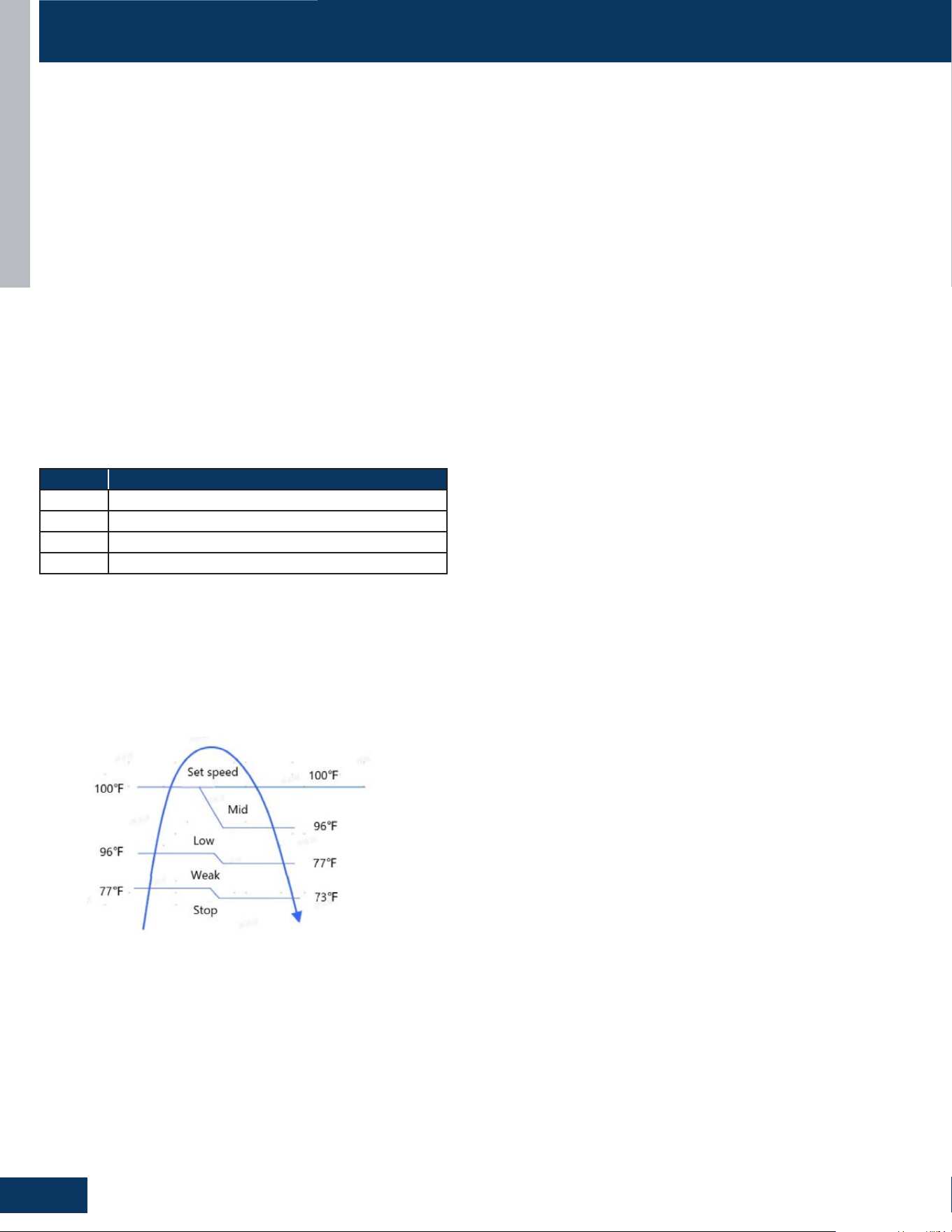
to the set operation.
5. When the coil temperature drops, the fan speed is judged
according to the hot cross temperature:
• Coil temperature is higher than 35°C, fan speed according to
the set operation.
• Coil temperature between 37°C and 35°C fan speed is mid
• Coil temperature between 35°C and 25°C fan speed is low
• Coil temperature between 25°C and 23°C fan speed is weak
• The fan stops when the coil temperature is lower than 23°C
Residual heat sending: the indoor fan will operate on low speed until
the coil temperature reaches 73°F or stop after 50 seconds.
The outdoor unit temperature sensors: outdoor ambient, defrost,
suction line, and compressor discharge, used in conjunction with the
indoor coil and room temperature sensors, provide information to
the outdoor control board to monitor the system and regulate the
speed of the compressor, the EEV and outdoor fan speed to achieve
the desired room temperature.
When heating has been satised, the compressor will turn o rst,
followed by the outdoor fan. The 4-way valve will de-energize 2
minutes after compressor stops.
To save energy, The indoor unit fan will continue to run at minimum
speed until indoor coil temperature reaches a minimum temperature,
when it will turn o.
If the system detects a malfunction, it may shut down or show an
error code on the indoor unit display board and/or I outdoor unit main
board LED.
Defrost
When the system initiates a call for defrost, the indoor fan motor
stops. The indoor unit display will not change. Any indoor unit
malfunctions will be ignored at this time. The system will cycle
through the defrost operation. Any indoor unit malfunctions will be
ignored until the compressor restarts and has been operating for 30
seconds. At the conclusion of the defrost cycle, the indoor fan will
enter the cold air proof operation. Heat mode resumes.
Automatic Heating Temperature Compensation
When the system is in heating mode, a temperature compensation
adjustment is added to the sensed temperature. This is intended to
adapt for temperature stratication in the conditioned environment
relative to the installation location of the indoor head.
Indoor Unit
To enter the heat mode, point the infrared remote controller at the
indoor unit and press the power button, then press the HEAT mode
button if not already set to heat mode.
The signals received by the infrared receiver are relayed to the main
board of the indoor unit to turn the system on and set it to heat
mode.
The indoor unit PCB will activate the display of the indoor unit,
illuminating the display and indicating the set temperature and
current status of the unit.
The indoor unit PCB will signal the stepper motor to open the louver
to a stationary position.
The PCB will power up the indoor fan motor after the outdoor unit
has started and heating of the indoor coil has taken place (see cold air
proof operation). The motor has a feed-back circuit which provides
information for controlling the speed of the fan motor.
There will be a 3 minutes delay when switching from high speed fan to
low speed fan. There will be no delay when switching from low speed
fan to high speed fan.
Cold Air Proof Operation
At initial start of heat mode, indoor blower will not be turned on
immediately until indoor coil temperature senses a minimum
temperature. This prevents cold air from being blown until the coil is
heated.
Fan Speed Ambient Indoor Air Temperature
Stop 8.8°F and higher above setpoint
Low Between 5.9°F and 8.7°F above setpoint
Medium Between 3.6°F and 5.8°F above setpoint
High Below setpoint and up to 3.5°F above setpoint
The indoor fan is controlled based on the coil temperature, as shown
in the gure above.
When the coil temperature rises, the fan speed is judged according to
the coil temperature:
1. At the end of heating or defrosting after the rst power on, the fan
stops when the coil temperature is lower than 25°C/ 77°F;
2. Coil temperature between 25°C/ 77°F and 35°C/ 96°F fan speed is
weak;
3. Coil temperature between 35°C/ 96°F and 37°C/ 100°F fan speed
is weak;
4. Coil temperature is higher than 37°C/ 100°F, fan speed according

INTRODUCTION
A9
ENGLISH
FUNCTIONS AND CONTROL
Temperature Sensors
The indoor unit has two sensors that provide temperature
information to the indoor unit main board. The sensors: a room
temperature sensor, and pipe temperature sensor, are used for
controlling the system during heat mode.
The resistance values of the sensors will vary with temperature. The
resistance to temperature values can be found using a temperature/
resistance chart specic to the sensor being checked.
Communication
The indoor and outdoor unit main boards communicate via a digital
signal on the wire connected to terminal 3 of each unit. A splice or
break in this wire will cause a communication error.
When a command is received from the remote control, the indoor
unit main board communicates with the outdoor unit to perform the
requested function.
Outdoor Unit
Upon a request for heat, the outdoor unit main board applies power
to the fan motor and compressor. Depending on system cycling,
there may be up to a 3 minute wait period before the compressor and
outdoor fan start.
WARNING: Do not measure compressor voltages, damage to the meter
may result.
If the room temperature is above the set temperature, yet lower than
2° F above the set temperature, the system will adjust the running
frequency of the compressor automatically.
The outdoor unit PCB also controls the position of the EEV
(Electronic Expansion Valve} to regulate the ow of refrigerant to the
indoor unit evaporator coil.
Temperature Sensors
Four temperature sensors located in the outdoor unit provide
information to the outdoor unit PCB for control of the system during
dry mode.
The outdoor ambient temperature sensor provides the temperature
of the air drawn into the condenser coil.
The defrost temperature sensor provides the temperature sensed at
the output of the condenser coil.
The suction line temperature sensor provides the temperature
sensed at the incoming suction line pipe.
The compressor discharge sensor provides the temperature sensed
at the discharge pipe of the compressor.
Call to Terminate Heating
The system will call to terminate heating when the indoor
temperature is equal to or higher than 2°F above the room set
temperature. The indoor control board will communicate to the
outdoor control board to de- energize the compressor. The outdoor
fan will run for 60 seconds before stopping. The 4-way valve will de-
energize 2 minutes after the compressor stops.
To stop heat mode, press the power button to turn the system o, or
change to another mode.
Auto Mode
With the system turned on, press the AUTO button on the remote
control. The system will change to the auto mode of operation.
As the room is cooled or heated, the system will automatically switch
between cool mode, fan mode, and heat mode. There is a minimum
15 minute operating time between mode changes.
Dry Mode
Overview
To enter the dry mode, point the infrared remote control at the
indoor unit and press the power button, then press the DRY mode
button if not already set to dry mode.
The signals received by the infrared receiver are relayed to the main
board of the indoor unit to turn the system on and set it to dry mode.
The indoor unit main board will illuminate the display, indicating the
set temperature and current status of the unit.
The PCB will then signal the louver stepper motor to open the louver
to either a stationary position, or one of several oscillating modes.
As the louver opens, the indoor fan motor will operate at the speed
last set. The fan motor has a feedback circuit which provides the
main board with information for controlling the speed of the fan
motor.
NOTE: It is recommended that Dry mode is not used for longer than a
4-hour period to minimize overowing the condensate drain pipe.
The temperature control range is 60°F - 86°F. This mode is used for
dehumidication.
Tr= room temperature Ts= set temperature
When Tr > Ts+ 4°F, the compressor will turn on and the indoor fan will
operate at the set speed.
When Ts ≤ Tr ≤ Ts+ 4°F, the compressor will operate at the high dry
frequency for 10 minutes, then at the low dry mode for 6 minutes.
The indoor fan will operate at low speed.
When Tr< Ts, the outdoor unit will stop, and the indoor fan will stop for
3 minutes, then operate at the low speed option.
Automatic fan speed:
• When Tr > Ts+ 9°F, High speed
• When Ts+ 5.4°F ≤ Tr< Ts+ 9°F, Medium speed
• When Ts+ 3.6°F ≤ Tr< Ts+ 5.4°F, Low speed
• When Tr< Ts+ 3.6°F, Light speed
Note: TURBO and QUIET mode must be set using the remote controller.
If the outdoor fan is stopped, the indoor fan will pause for 3 minutes.
If the outdoor fan is stopped for more than 3 minutes, and the
compressor is still operating, the system will change to light speed
mode.
Temperature Sensors
The indoor unit has two sensors that provide temperature
information to the PCB. An ambient temperature sensor and pipe
temperature sensor are used for controlling the system during
dry mode. The resistance values of the sensors will vary with
temperature. The resistance to temperature values can be found
using a temperature /resistance chart specic to the sensor being
checked.
INTRODUCTION
A10
ENGLISH
FUNCTIONS AND CONTROL
Protection Functions
These functions limit the operation of the system when
encountering the normal operating limits of the equipment.
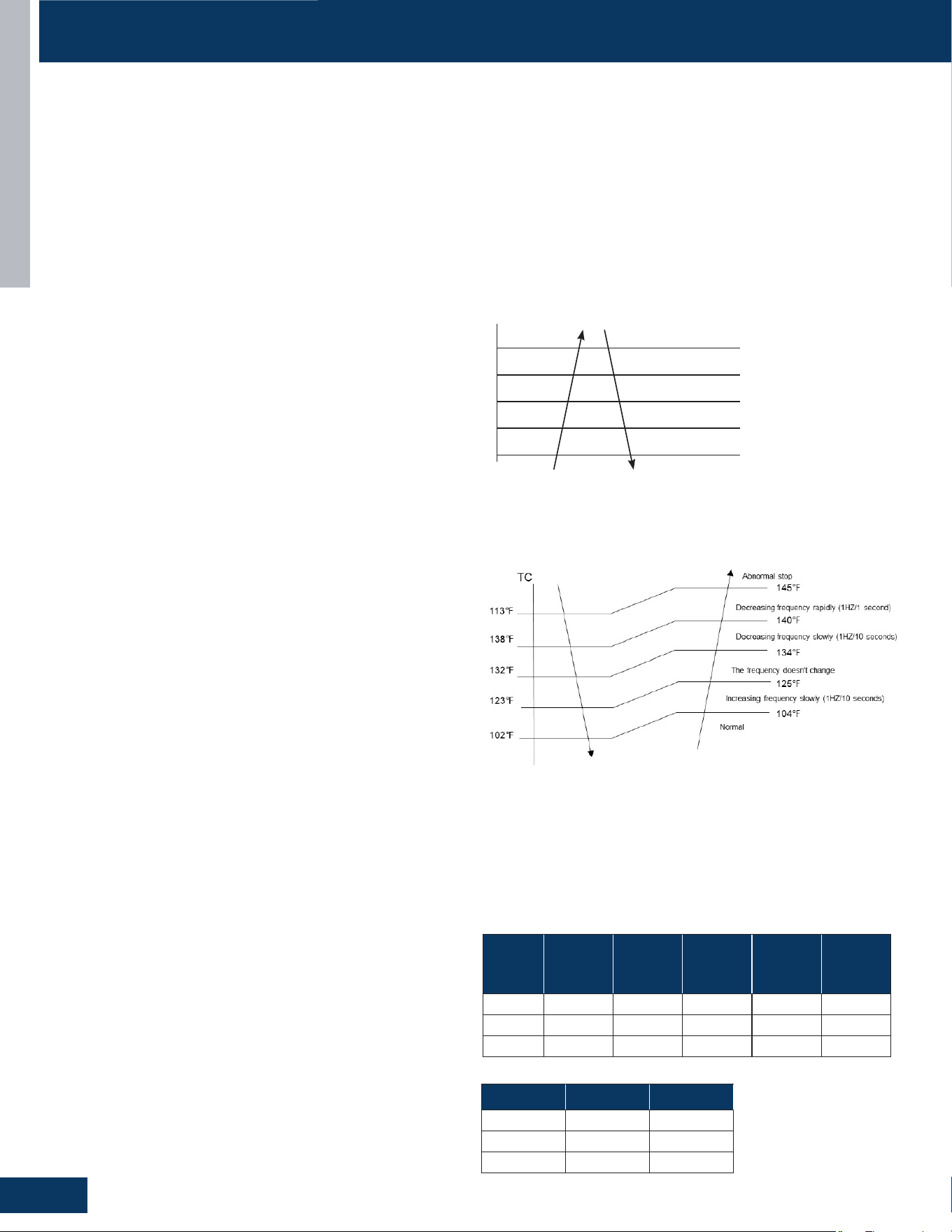
Compressor High Temperature
The compressor discharge pipe sensor (exhaust temp) senses the
temperature of the refrigerant exiting the compressor The sensed
temperature received from the sensor by the control circuitry will
cause the compressor frequency to increase or decrease (see chart
below) If a temperature of >= 230 °F is sensed for 2 seconds, an
exhaust overheating protection error code will be indicated at the
outdoor unit.
TTC
230°F
Abnormal stop
Decreasing frequency rapidly (1HZ/1 second)
Decreasing frequency slowly (1HZ/10 seconds)
The frequency doesn’t change
Increasing frequency slowly (1HZ/10 seconds)
Normal
208.4°F
215.6°F
203°F
197.6°F
Overheating Protection for Indoor Unit
A sensor monitors coil temperature in both heating and cooling
modes, and causes the compressor to speed up, slow down, or stop
Model
Cooling
Increase
Point
Cooling
Decrease
Point
Heating
Increase
Point
Heating
Decrease
Point Stop Point
09K 5.5A 6.5A 7A 8A 10.5A
12K 5.5A 6.5A 7A 8A 10.5A
18K 12A 12A 13A 13A 14A
Model Cooling Heating
09K 20-66 Hz 20-118 Hz
12K 12-66 Hz 12-110 Hz
18K 12-49 Hz 13-106 Hz
Communication
The indoor and outdoor unit main boards communicate via a digital
signal on the wire connected to terminal 3 of each unit. A splice or
break in this wire will cause a communication error.
When a command is received from the remote control, the indoor
unit main board communicates with the outdoor unit main board via
the terminal 3 wire to perform the requested function.
Outdoor Unit
Upon a request for dry mode, the outdoor unit main board applies
power to the fan motor and compressor. Depending on system
cycling, there may be up to a 3 minute wait period before the
compressor and outdoor fan start.
WARNING: Do not measure compressor voltages, damage to the meter
may result.
The outdoor unit PCB also controls the position of the EEV
(Electronic Expansion Valve} to regulate the ow of refrigerant to the
indoor unit evaporator coil.
Temperature Sensors
Four temperature sensors located in the outdoor unit provide
information to the outdoor unit PCB for control of the system during
dry mode.
The outdoor ambient temperature sensor provides the temperature
of the air drawn into the condenser coil.
The defrost temperature sensor provides the temperature sensed at
the output of the condenser coil.
The suction line temperature sensor provides the temperature
sensed at the incoming suction line pipe.
The compressor discharge sensor provides the temperature sensed
at the discharge pipe of the compressor.
To stop dry mode, press the power button to turn the system o, or
change to another mode.
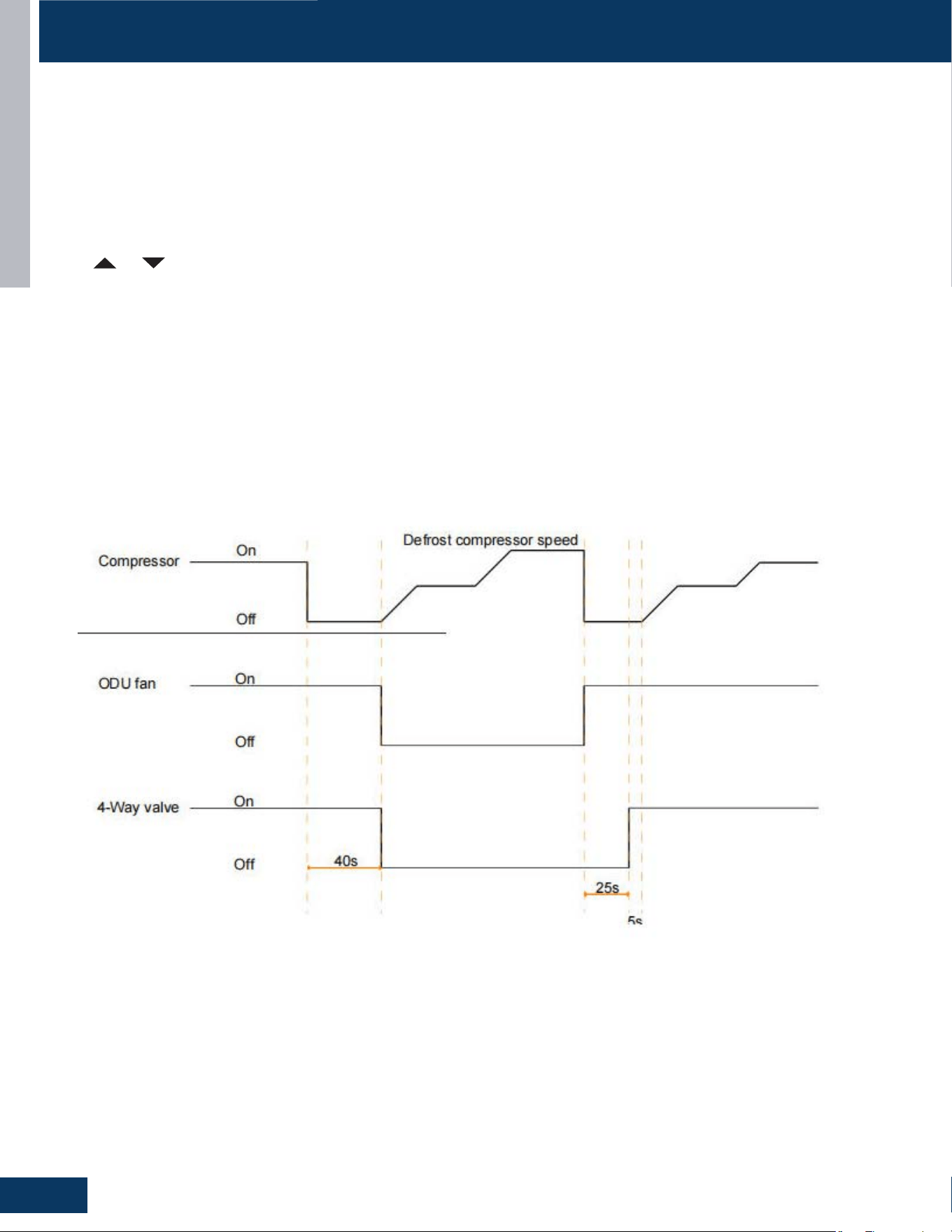
Defrost Operation
To enter the defrost mode, the compressor must have accumulated
10 minutes of run time, and 45 minutes of accumulated run time
since the last defrost cycle.
When the defrost cycle begins, the following conditions take place:
1. Indoor fan motor stops.
2. Compressor stops for 40 seconds.
3. After 40 seconds, the 4-way valve shifts to cooling position and
outdoor fan stops. Compressor start again.
4. About 1 minute, the compressor accelerates to the defrost
frequency.
5. The outdoor unit will now defrost. Defrost cycle runs continuously
for approximately 10 minutes, unless the condenser maintains
a temperature above 48°F for 60 seconds, or the condenser
maintains a temperature above 59°F for 5 seconds.
Upon exiting the defrost cycle, the following conditions will take
place:
1. The compressor will stop.
2. The outdoor fan will operate at high speed.
3. 25 seconds later the 4-way valve will shift to the heating mode.
4. 30 seconds later the compressor will start, and the system
resumes normal operation.
Compressor frequencies:
Compressor Over-Current Protection
If the current draw of the compressor at startup is greater than the
values listed on the chart below for approximately 5 seconds, the
compressor will stop. After 3 minutes the compressor will restart. If
the over-current condition occurs 3 times in 20 minutes, the system
will lock-out, and a code will be indicated at the outdoor unit. It will
be necessary to remove power to the system to reset the lock-out
condition.
INTRODUCTION
A11
ENGLISH
FUNCTIONS AND CONTROL
Outdoor Temperature Pan Heater
> 37°F (3°C) OFF
28°F (-2°C) to 34°F (1°C) OFF 20min, ON 10min
10°F (-12°C) to 25°F (-4°C) OFF 15min, ON 15min
< 10°F (-12°C) ON
Indoor Coil Anti-Freeze Protection
The temperature sensed by the coil sensor is used to determine at
what speed the compressor is to run to avoid the coil temperature
being too cold.
TCI_Indoor: Indoor unit pipe sensor temperature
tS: Outdoor unit Suction Line sensor temperature
• When Min(TCI_indoor, (TCI_indoor + tS)/2) < TCI1, the frequency of
the compressor decreases at the rate of 1HZ / 1 second.
• When Min(TCI_indoor, (TCI_indoor + tS)/2) < TCI2, the frequency of
the compressor decreases at the rate of 1HZ / 10 second.
• When TCI_indoor begins to rise again, and TCI2 ≤ Min(TCI_indoor,
(TCI_indoor + tS)/2) ≤ TCI3, the frequency of the compressor does
not change.
• When TCI3 < Min(TCI_indoor, (TCI_indoor + tS)/2) < TCI4, the
frequency of the compressor increases at the rate of 1HZ / 10
second.
Example: if Min(TCI_indoor, TCI_indoor + tS)/2) ≤ 32°F sustains
for 2 minutes, the outdoor unit will stop and indicate an underload
malfunction code at the outdoor unit. The compressor stops for a
minimum of 3 minutes. When Min(TCI_indoor, TCI_indoor + tS)/2) >
TCI4, the compressor will restart.
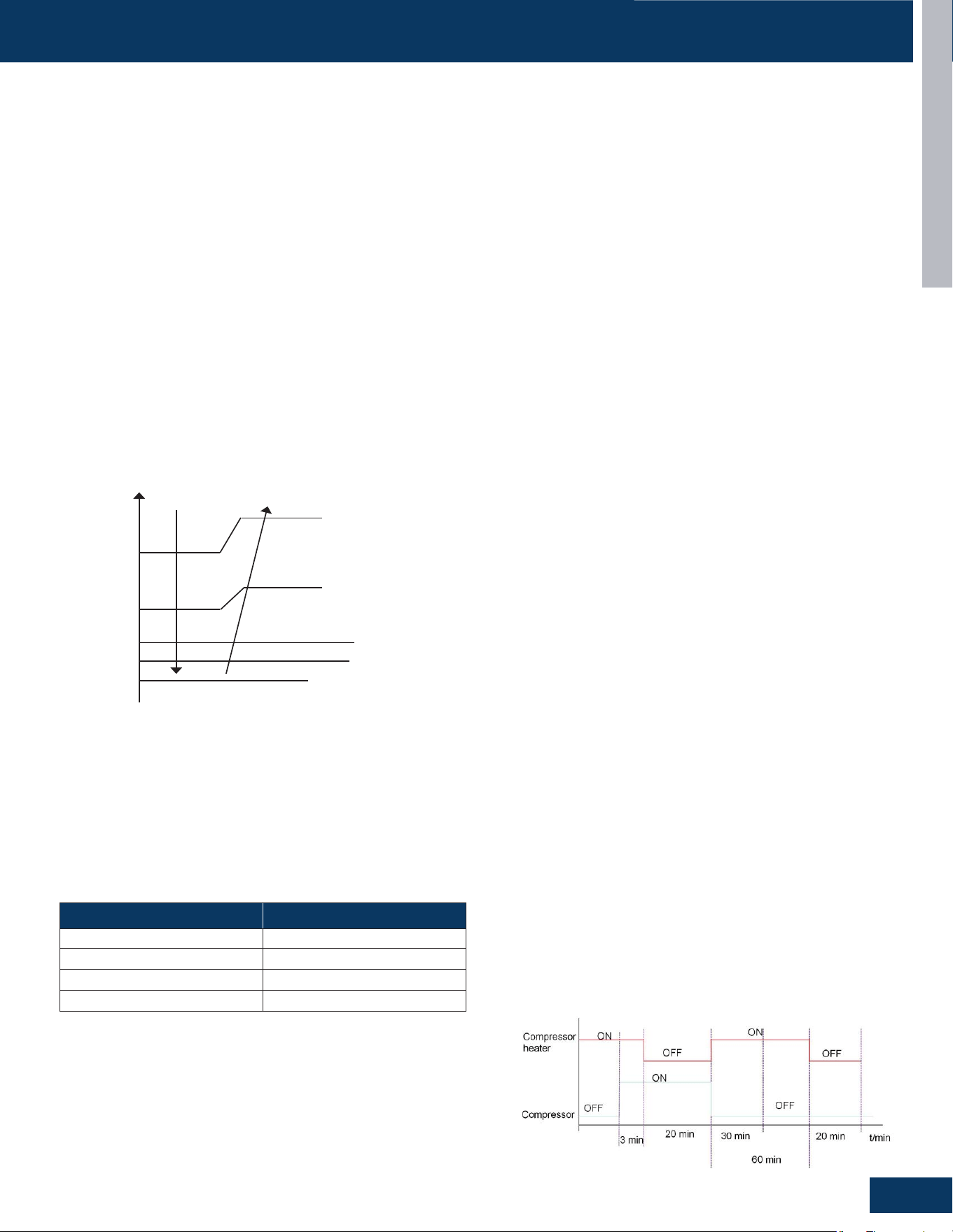
Base Pan Heater
To keep condensate water from freezing inside the cabinet, a base
pan heater is installed at the factory.
Operation condition:
a. It will start while defrosting process is running.
b. If AC is not in defrost process, it will work refer to the chart below
for the operating parameters.
52°F
46°F
Decreasing slowly
Decreasing rapidly
Stop
Keeping frequency
Increases slowly
Tpg4 = 48°F
Tpg3 = 45°F
Tpg2 = 41°F
3Tpg1 = 7°F
32°F
Special Functions
Auto Restart
When this is enabled, the following functions will automatically
resumes after a power loss:
• ON/OFF State, Mode of Operation, Fan Speed, Temperature
Setpoint, Louver Swing settings.
• If there was a timer set , it will be canceled upon restart.
Enable auto restart:
Press sleep Button 10 times within 7 seconds. Unit will beep 4 times
to conrm.
Disable auto restart:
Press sleep Button 10 times within 7 seconds. Unit will beep 2 times
to conrm.
Wired controller can control the function by dip switch SW1-4: o is
enable, on is disable.
Enhanced/Timed Defrost
via Remote Controller
Setting method:
1. Set to HEAT Mode
2. Set to 30°C/86°F
3. Set High Fan Speed
4. Press Temperature+ Button 10 times within 7 seconds
5. Unit will Beep 7 times to Conrm.
Cancel method:
Same process as Setting Method. Hear Unit Beep 5 times to conrm
of cancel function.
Indoor Temperature Display
This function will allow you to set the display to show either the
Ambient temperature or the setpoint:
Set temperature:
• Press the Light button 10 times within 5 second. Unit will Beep 4
times to conrm.
Ambient temperature:
• Press the Light button 10 times within 5 second. Unit will Beep 2
times to conrm.
Crankcase (Compressor) Heater
Operation logic:
a. If outdoor ambient temperature is 5°C, compressor heater is
OFF.
b. If outdoor ambient temperature is <3°C, compressor heater
functions as shown:
INTRODUCTION
A12
ENGLISH
FUNCTIONS AND CONTROL
Temperature Compensation
Set Temperature:
1. Apply power to the unit.
2. Set to Cooling Mode or Heating Mode
3. Set the temperature to 24°C.
4. Press the SLEEP button 7 times within 5 seconds. Indoor PCB will beep 2 times to conrm.
5. 24°C will be the starting/reference point for the Temperature Compensation.
6. Press or on the controller to adjust compensation temperature value. Temperature Compensation can be adjusted from -8°C to
+6 °C. (Example: if you want to set the Temperature Compensation value by 4°C, then set the temperature to 28°C.)
7. Once the desired value has been selected, turn OFF the unit to save the compensation settings.
Timed Defrost
Logic:
1. After receiving the defrost signal, the compressor will stop.
2. 40 seconds later, the four-way valve is reversed and the outdoor fan stops.
3. The compressor gradually increases frequency to the highest defrosting frequency.
4. After defrosting completes, the outdoor fan motor starts, the compressor stops, and the four-way valve is opened after 25 seconds
5. The compressor will start after 5 seconds.

OUTDOOR UNITS
B1
ENGLISH
OUTDOOR UNITS
TABLE OF CONTENTS
COMPONENTS .......................................................................................................................................................................B2
Outdoor Component Identication: 1G09ED2BEA .............................................................................................................B2
Terminal Block ......................................................................................................................................................................... B3
Power Factor Reactor .............................................................................................................................................................B3
Compressor ............................................................................................................................................................................B3
Fan Motor ................................................................................................................................................................................B3
Temperature Sensors ............................................................................................................................................................. B4
4-Way Valve .............................................................................................................................................................................B4
Electronic Expansion Valve ....................................................................................................................................................B4
Accumulator ............................................................................................................................................................................B5
Refrigerant Strainers ..............................................................................................................................................................B5
Compressor Heater ................................................................................................................................................................B5
Base Pan Heater ......................................................................................................................................................................B5
Outdoor Component Identication: 1G12ED2BEA .............................................................................................................B6
Terminal Block ......................................................................................................................................................................... B7
Power Factor Reactor .............................................................................................................................................................B7
Compressor ............................................................................................................................................................................B7
Fan Motor ................................................................................................................................................................................B7
Temperature Sensors ............................................................................................................................................................. B8
4-Way Valve .............................................................................................................................................................................B8
Electronic Expansion Valve ....................................................................................................................................................B8
Accumulator ............................................................................................................................................................................B9
Refrigerant Strainers ..............................................................................................................................................................B9
Compressor Heater ................................................................................................................................................................B9
Base Pan Heater ......................................................................................................................................................................B9
Outdoor Component Identication: 1G18ED2BEA ...........................................................................................................B10
Terminal Block ....................................................................................................................................................................... B11
Power Factor Reactor ...........................................................................................................................................................B11
Compressor ..........................................................................................................................................................................B11
Fan Motor ..............................................................................................................................................................................B11
Temperature Sensors ...........................................................................................................................................................B12
4-Way Valve ...........................................................................................................................................................................B12
Electronic Expansion Valve ..................................................................................................................................................B12
Accumulator ..........................................................................................................................................................................B13
Refrigerant Strainers ............................................................................................................................................................B13
Compressor Heater ..............................................................................................................................................................B13
Base Pan Heater .................................................................................................................................................................... B13
Outdoor Unit Control Board ................................................................................................................................................B14
WIRING DIAGRAM ................................................................................................................................................................. B16
DIP SWITCH SETTINGS
........................................................................................................................................................B17
SERVICE PROCEDURES
........................................................................................................................................................B18
Checking the Outdoor Unit Sensors ...................................................................................................................................B18
Checking the Reversing Valve Coil ....................................................................................................................................... B18
Checking the Compressor Windings ................................................................................................................................... B18
Checking the EEV Coil ..........................................................................................................................................................B18
Checking the Outdoor DC Fan motor .................................................................................................................................B18
Checking the Compressor Heater .......................................................................................................................................B19
Checking the Base Pan Heater .............................................................................................................................................B19
Checking the Reactor ...........................................................................................................................................................B19
1G09ED2BEA
1G12ED2BEA
1G18ED2BEA
OUTDOOR UNITS
B2
ENGLISH
ENGLISH
OUTDOOR UNITS
B-2
COMPONENTS
12
6
9
13
2
5
3
10
8
1
11
14
15
4
7
ENGLISH
OUTDOOR UNITS
B-2
COMPONENTS
12
6
9
13
2
5
3
10
8
1
11
14
15
4
7
ENGLI SH
OUTDOOR UNITS
B-2
COMPONENTS
12
6
9
13
2
5
3
10
8
1
11
14
15
4
7
ENGLI SH
OUTDOOR UNITS
B-2
COMPONENTS
12
6
9
13
2
5
3
10
8
1
11
14
15
4
7
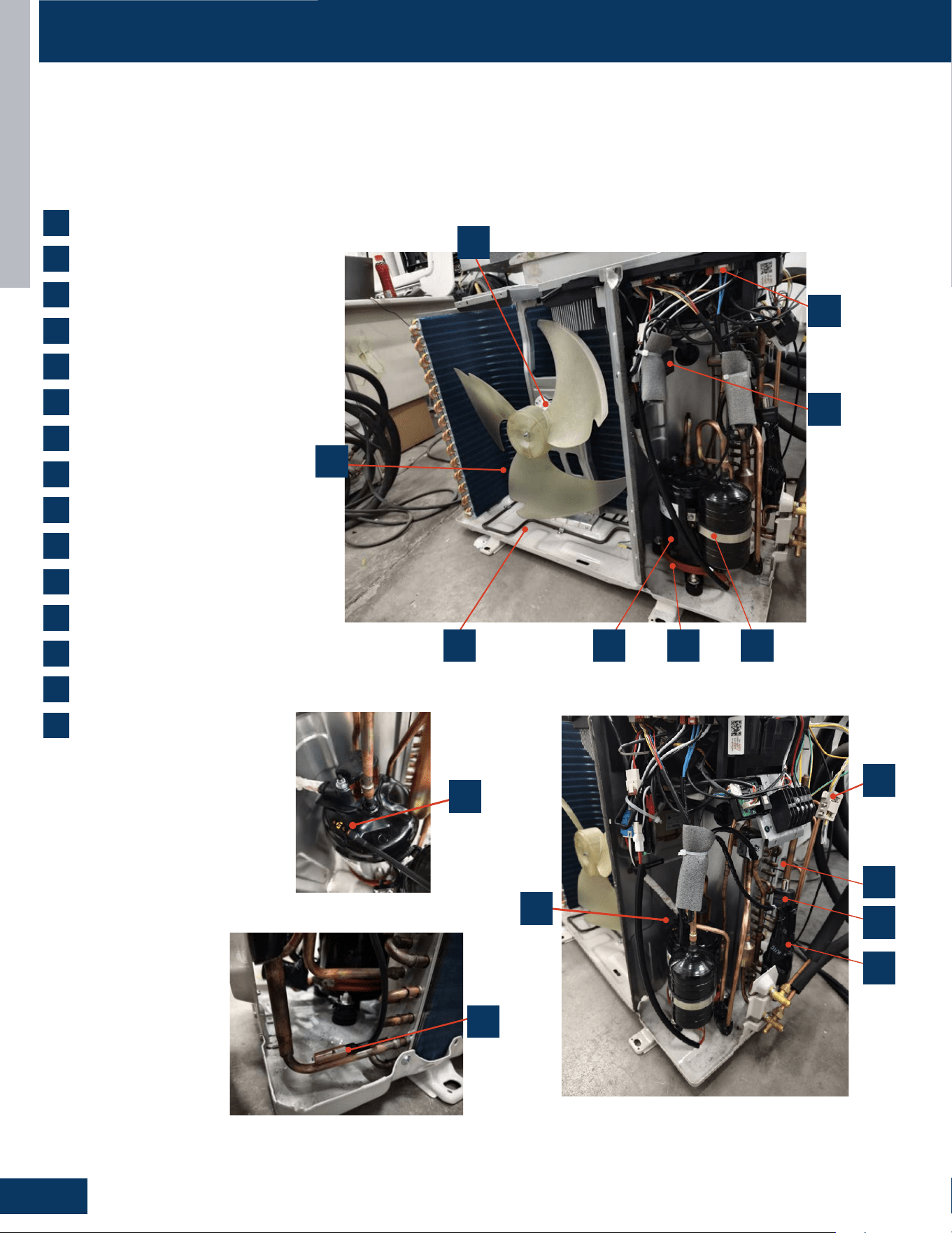
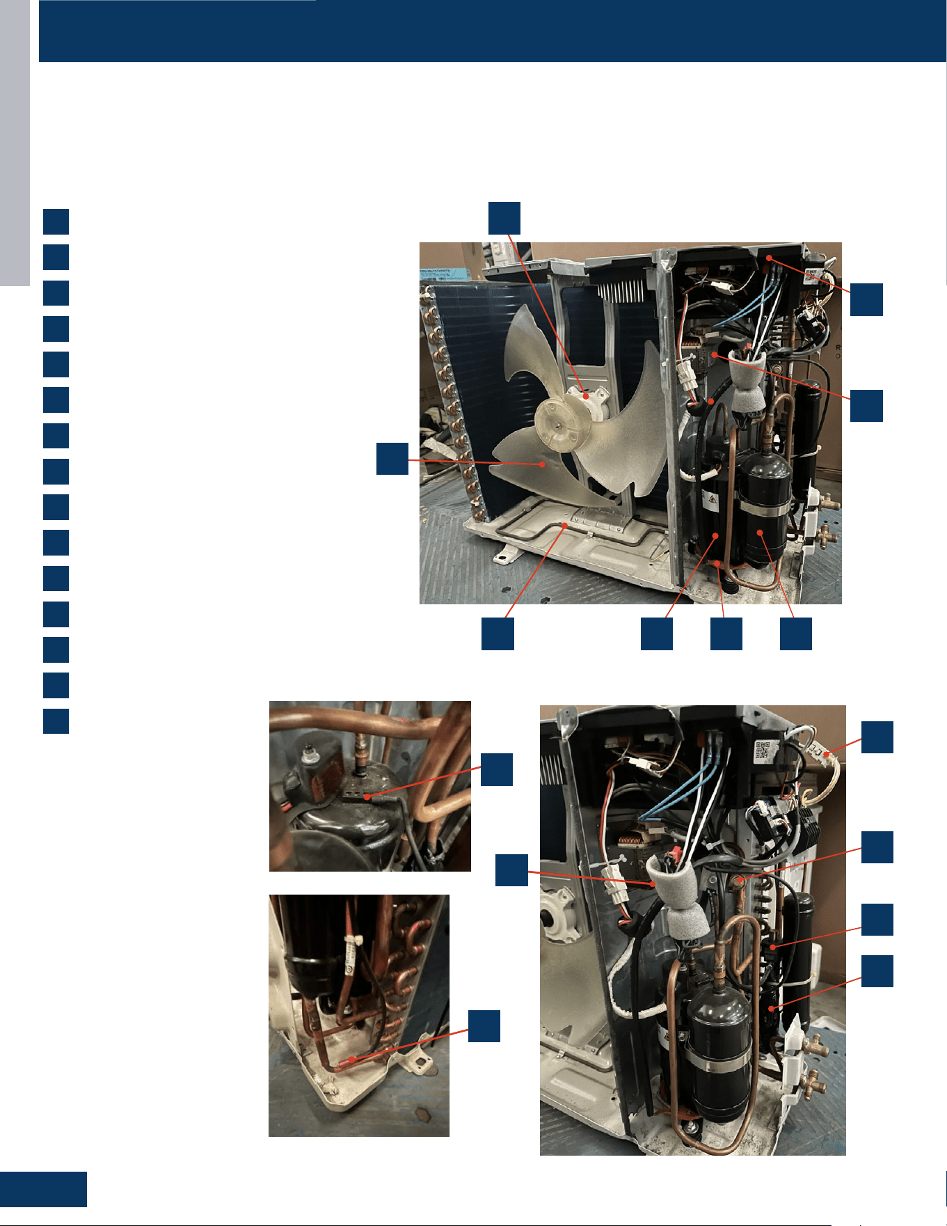
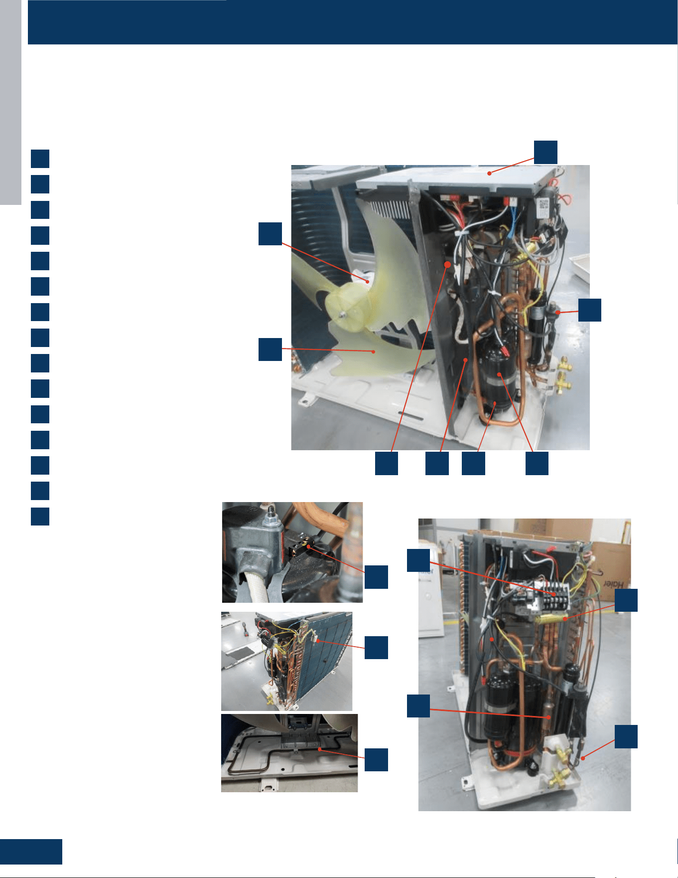
COMPONENTS
4-Way Valve
Accumulator
Compressor
Defrost Temperature Sensor
Discharge Temperature Sensor
Electronic Expansion Valve
Refrigerant Strainers
Ambient Temperature Sensor
Fan Motor
Power Factor Reactor
Terminal Block
Power Control Board (PCB)
Fan Blade
Compressor Heater
Base Pan Heater
1
8
2
9
3
10
4
11
5
5
12
6
13
7
1
8
4
6
7
14
15
2
9
3
10
11
12
13
1415
The outdoor unit has a PCB that integrates the control functions and power functions into one PCB. Sensors monitor key temperatures
throughout the system to manage operational decisions.
Outdoor Component Identication: 1G09ED2BEA
OUTDOOR UNITS
B3
ENGLISH
COMPONENTS
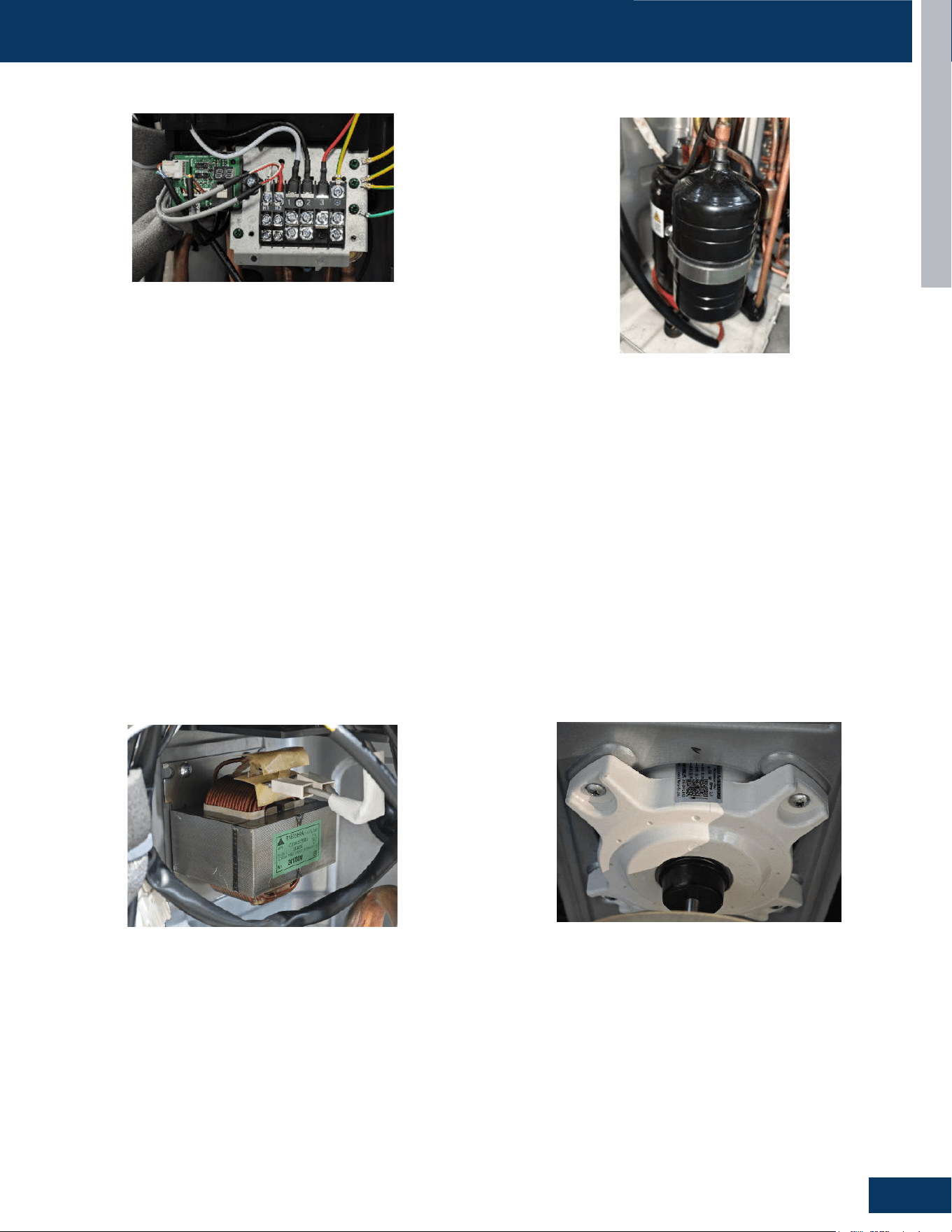
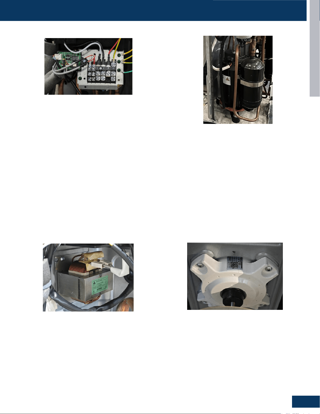
The Reactor is a power lter. It is unlikely to ever have an electrical
failure of this component.
The Reactor of all outdoor units is electrically connected to the IPM
on terminal connections CN-5 and CN-6 .
The outdoor unit is powered by 208/230 volt single phase electricity
connected at the terminal block.
Terminals 1 and 2 connect this voltage to the system. H1 and H2 is
used for OTA .
The number 3 terminal is communication that connects wiring
between the indoor and outdoor units. A ground terminal connects
the outdoor unit to the line voltage power source.
The indoor unit is also powered by the same electrical supply as
the outdoor unit. Only AWG 14-4 stranded copper wire is allowed
connected to the Terminal Block block at the outdoor unit and is run
to the same terminals on the indoor terminal block.
When installing the eld supplied wiring, make certain the wire gauge
is correct. There should not be any electrical wiring splices between
the indoor unit and outdoor unit wire connection 3. This wire is
used to carry communication data between the indoor and outdoor
units. A wiring splice where wires are twisted in a wire nut may cause
deformation of the communication signal. If communication is lost
between the indoor and outdoor units, an ERROR CODE E7 will occur.
The fan motor is a variable speed DC motor. The required speed is
calculated by the PCB. The motor is electrically connected to the PCB
via PLUG CN-10.
In COOL MODE, the motor will slow down as outdoor air temperature
falls. In HEAT MODE, the motor will increase speed as the outdoor air
temperature falls.
The compressor is a three phase DC inverter driven rotary type,
capable of variable speed operation. The compressor operating
frequency will be determined by the temperature dierence between
set point and room temperature.
The compressor of all outdoor units is electrically connected to the
IPM on terminal connections CN-7, CN-8 and CN-9.
Protection of the compressor will be provided by the discharge
temperature sensor, the suction line temperature sensor, and the
over current protection parameter in the PCB.
Terminal Block Compressor
Fan MotorPower Factor Reactor
ENGLI SH
OUTDOOR UNITS
B-7
COMPONENTS
31-5000931 Rev. 0
ENGLI SH
OUTDOOR UNITS
B-7
COMPONENTS
31-5000931 Rev. 0
ENGLI SH
OUTDOOR UNITS
B-7
COMPONENTS
31-5000931 Rev. 0
ENGLI SH
OUTDOOR UNITS
B-7
COMPONENTS
31-5000931 Rev. 0
OUTDOOR UNITS
B4
ENGLISH
COMPONENTS
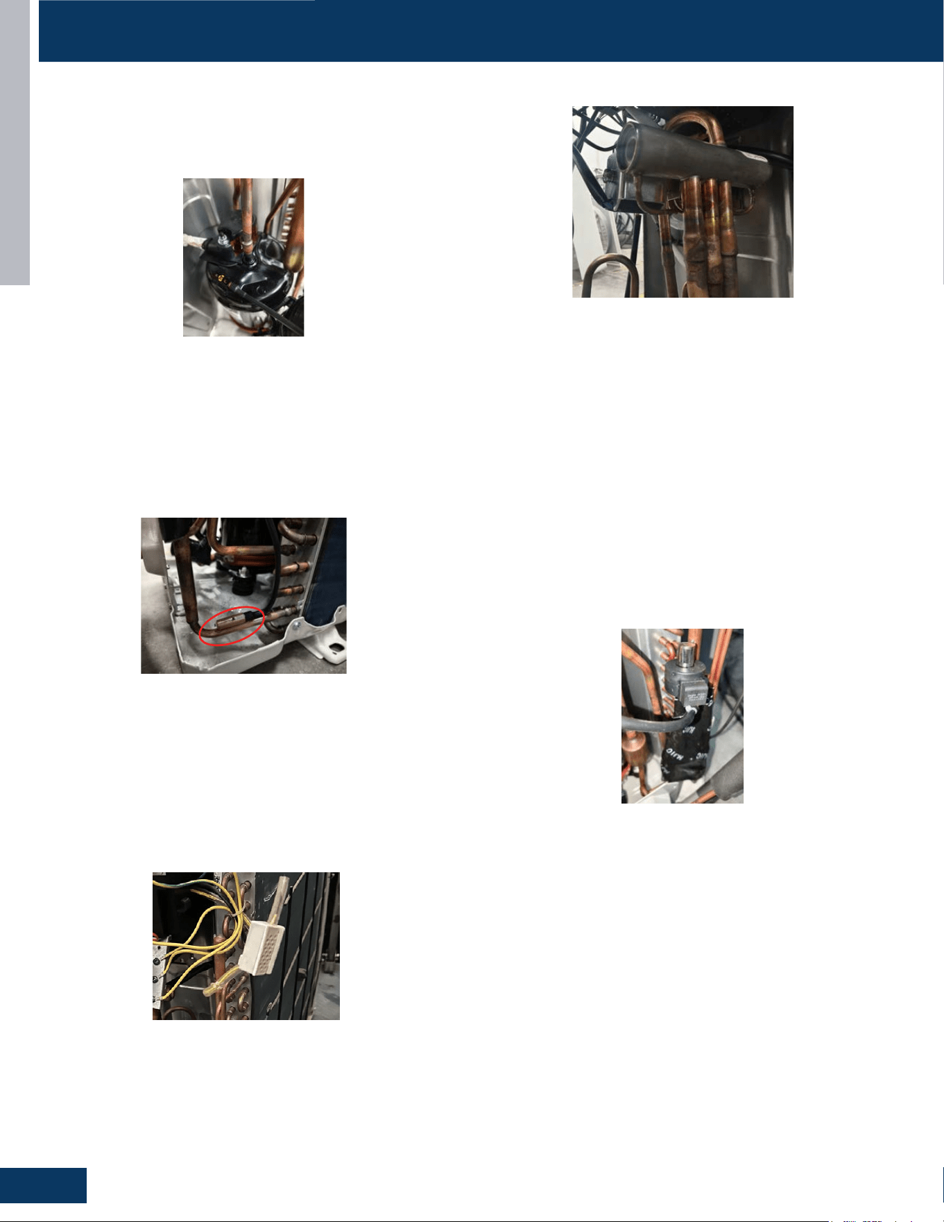
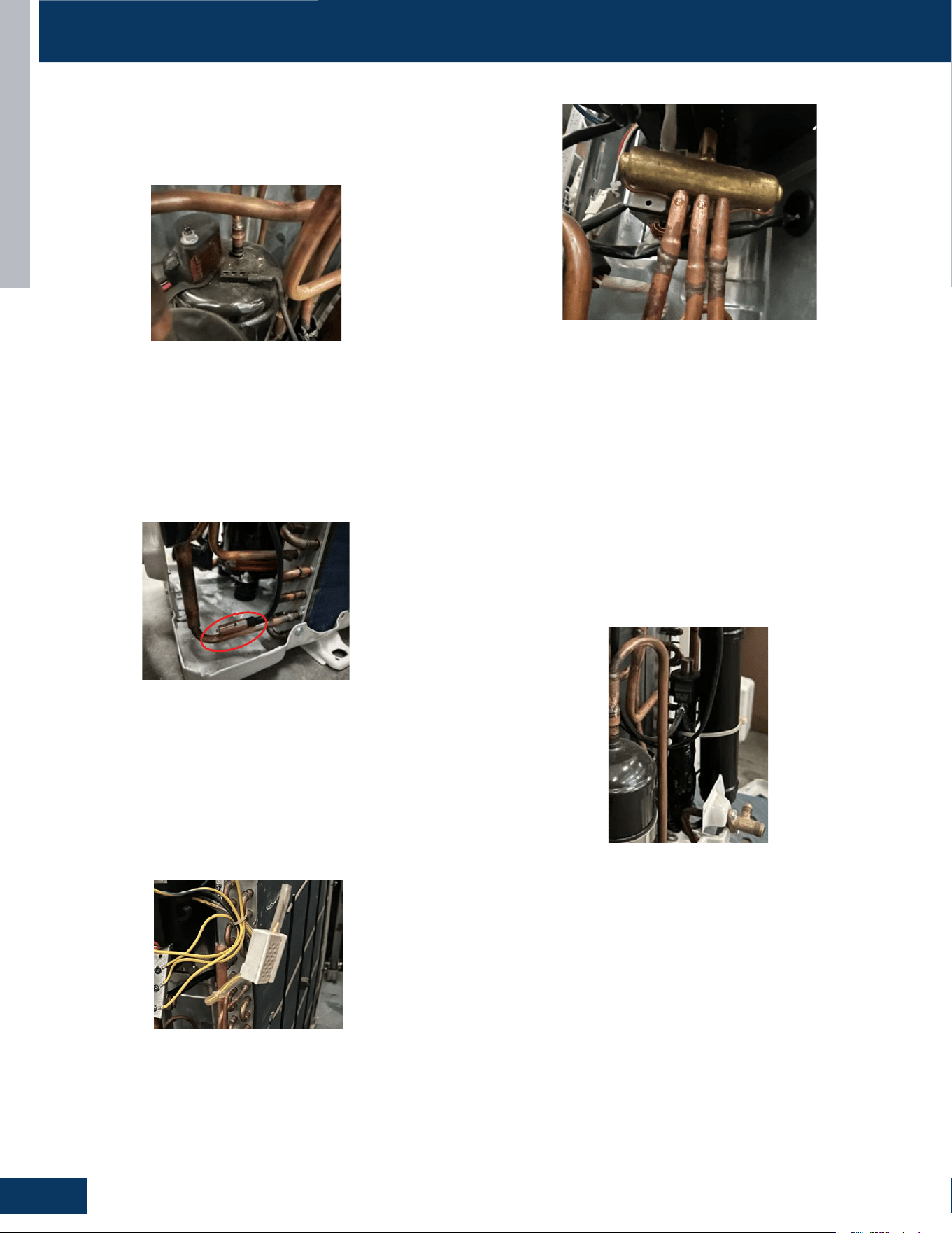
4-Way Valve
The 4-Way Valve redirects the ow of refrigerant in the piping circuit
to allow the system to reverse the functions of the indoor and
outdoor coils. When de-energized in COOL MODE, the valve will
direct the refrigerant hot gas to the outdoor coil. When energized in
HEAT MODE, the valve will direct the hot gas to the indoor coil.
The valve ow direction capability is controlled by an electrical
solenoid. When energized with 208/230 VAC, the solenoid will
magnetically move an internal slide within the 4-Way Valve to change
the direction of refrigerant ow.
The 4-Way Valve is electrically connected to the Power Control Board
at PLUG CN-11.
Electronic Expansion Valve
The metering device is an electronic expansion valve. The valve
consists of an electrical operator and a valve body with internal
variable size orice. When operating, the PCB will send pulses of
voltage to the electrical operator. The operator will then magnetically
move the position of the metering orice pin to vary refrigerant ow.
The metering device position is determined by input from a
Discharge Temperature Sensor. The EEV will change the internal
orice size to maintain an acceptable level of superheat.
During COOL MODE the valve meters low pressure refrigerant to
the indoor coil. During HEAT MODE the valve meters low pressure
refrigerant to the outdoor coil.
The electrical expansion valve is electrically connected to the Power
Control Board at PLUG CN-16.
Temperature Sensors
Discharge Temperature Sensor
The Discharge Temperature Sensor is a negative coecient
thermistor that senses the temperature of the compressor hot
gas. The PCB monitors the temperature of the compressor hot gas
and will make inverter speed changes in response to input from this
device.
This sensor connects to the Power Control Board at PLUG CN-15
ENGLI SH
OUTDOOR UNITS
B-7
COMPONENTS
31-5000931 Rev. 0
ENGLI SH
OUTDOOR UNITS
B-7
COMPONENTS
31-5000931 Rev. 0
Defrost Temperature Sensor
The Defrost Temperature Sensor is a negative coecient thermistor
that will change resistance in response to outdoor coil temperature
changes. The PCB monitors the temperature of the outdoor coil to
determine when the system should perform a defrost cycle. The
sensor also monitors coil temperature during defrost cycles to
determine termination conditions.
This sensor connects to the Power Control Board at PLUG CN-15.
ENGLI SH
OUTDOOR UNITS
B-7
COMPONENTS
31-5000931 Rev. 0
Outdoor Ambient Temperature Sensor
The Ambient Temperature Sensor is a negative coecient
thermistor that will change resistance in response to outdoor air
temperature changes. The PCB monitors the temperature of the
outdoor air to determine fan speed requirements and inverter
speed. The sensor also plays a role in calculation of required defrost
conditions.
This sensor connects to the Power Control Board at PLUG CN-15
ENGLI SH
OUTDOOR UNITS
B-7
COMPONENTS
31-5000931 Rev. 0
ENGLI SH
OUTDOOR UNITS
B-7
COMPONENTS
31-5000931 Rev. 0
These 3 sensors are part of an assembly and will all be changed
together.
OUTDOOR UNITS
B5
ENGLISH
COMPONENTS
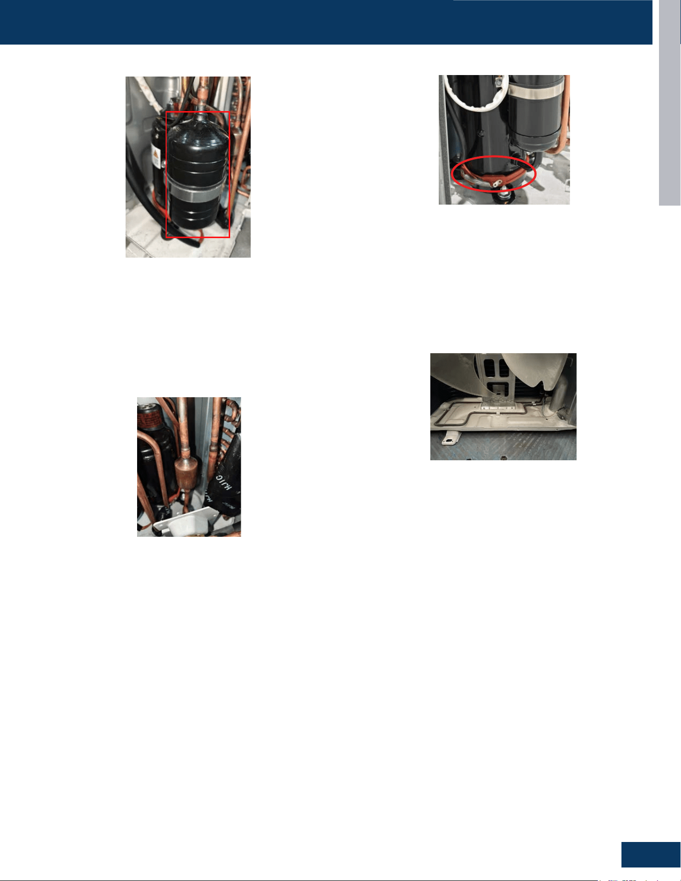
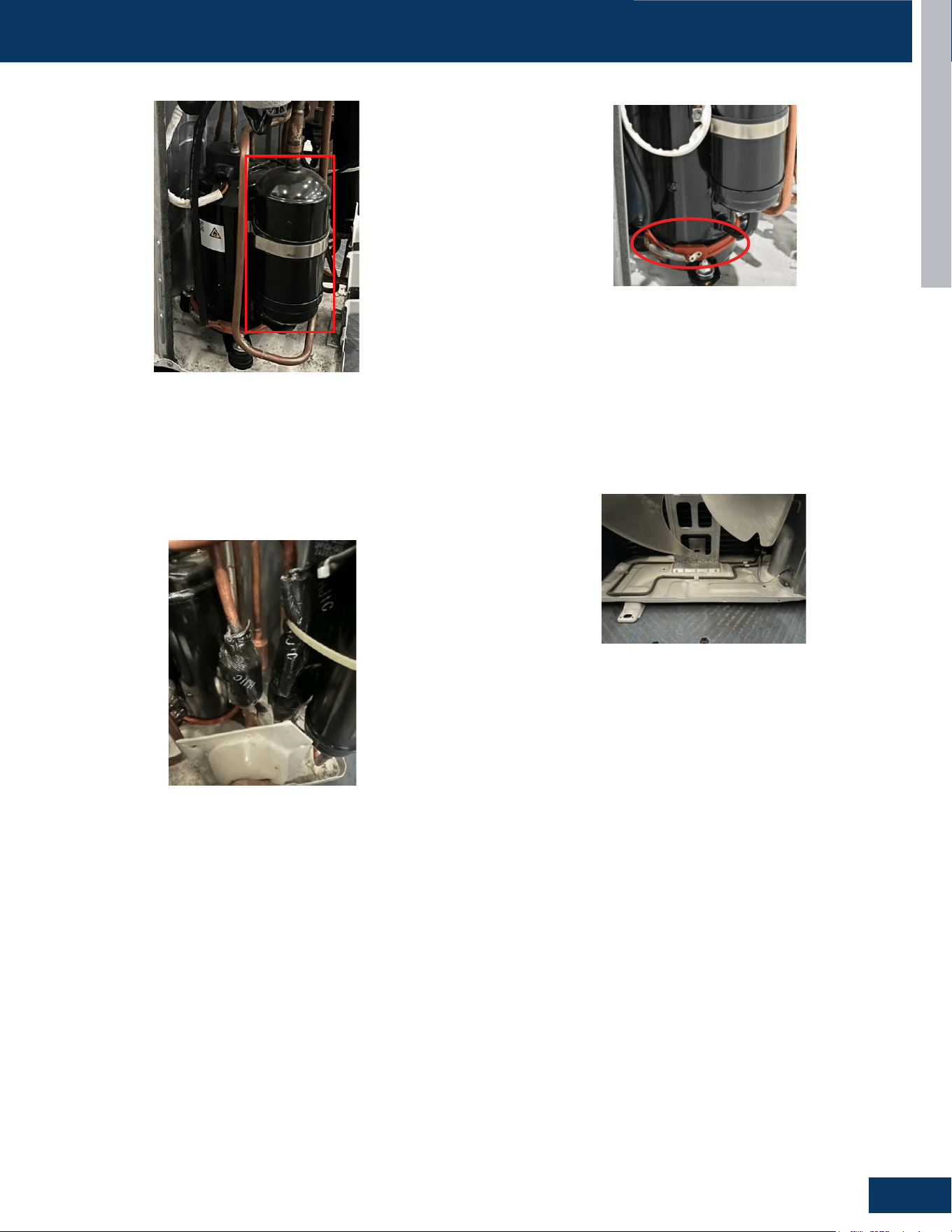
Accumulator
The Accumulator is located in the suction line circuit at the
entrance to the compressor. The accumulator helps prevent
liquid refrigerant from entering the compressor during run
operation.
Compressor Heater
The Compressor heater is used to preheat the compressor and assist
the start of the compressor at low temperature. The Compressor
Heater is electrically connected to the Power Control Board at PLUG
CN-13 and energized with 208/230 VAC.
Base Pan Heater
To keep condensate water from freezing inside the cabinet, a base
pan heater is installed at the base pan. The Base Pan Heater is
electrically connected to the Power Control Board at PLUG CN-12
and energized with 208/230 VAC.
Refrigerant Strainers
The system has debris-catching strainers that protect internal
system components from contaminants in the refrigerant. The
strainer is a permanent part that is not typically replaced.
ENGLI SH
OUTDOOR UNITS
B-7
COMPONENTS
31-5000931 Rev. 0
ENGLI SH
OUTDOOR UNITS
B-7
COMPONENTS
31-5000931 Rev. 0
ENGLI SH
OUTDOOR UNITS
B-7
COMPONENTS
31-5000931 Rev. 0
ENGLI SH
OUTDOOR UNITS
B-7
COMPONENTS
31-5000931 Rev. 0
OUTDOOR UNITS
B6
ENGLISH
ENGLI SH
OUTDOOR UNITS
B-2
COMPONENTS
12
6
9
13
2
5
3
10
8
1
11
14
15
4
7
ENGLI SH
OUTDOOR UNITS
B-2
COMPONENTS
12
6
9
13
2
5
3
10
8
1
11
14
15
4
7
ENGLI SH
OUTDOOR UNITS
B-2
COMPONENTS
12
6
9
13
2
5
3
10
8
1
11
14
15
4
7
COMPONENTS
4-Way Valve
Accumulator
Compressor
Defrost Temperature Sensor
Discharge Temperature Sensor
Electronic Expansion Valve
Refrigerant Strainers
Ambient Temperature Sensor
Fan Motor
Power Factor Reactor
Terminal Block
Power Control Board (PCB)
Fan Blade
Compressor Heater
Base Pan Heater
1
8
2
9
3
10
4
11
5
5
12
6
13
7
1
8
4
6
7
14
15
2
9
3
10
11
12
13
1415
The outdoor unit has a PCB that integrates the control functions and power functions into one PCB. Sensors monitor key temperatures
throughout the system to manage operational decisions.
Outdoor Component Identication: 1G12ED2BEA
OUTDOOR UNITS
B7
ENGLISH
COMPONENTS
The Reactor is a power lter. It is unlikely to ever have an electrical
failure of this component.
The Reactor of all outdoor units is electrically connected to the IPM
on terminal connections CN-5 and CN-6.
The outdoor unit is powered by 208/230 volt single phase electricity
connected at the terminal block.
Terminals 1 and 2 connect this voltage to the system.
The number 3 terminal is communication that connects wiring
between the indoor and outdoor units. A ground terminal connects
the outdoor unit to the line voltage power source.
The indoor unit is also powered by the same electrical supply as
the outdoor unit. Only AWG 14-4 stranded copper wire is allowed
connected to the Terminal Block block at the outdoor unit and is run
to the same terminals on the indoor terminal block.
When installing the eld supplied wiring, make certain the wire gauge
is correct. There should not be any electrical wiring splices between
the indoor unit and outdoor unit wire connection 3. This wire is
used to carry communication data between the indoor and outdoor
units. A wiring splice where wires are twisted in a wire nut may cause
deformation of the communication signal. If communication is lost
between the indoor and outdoor units, an ERROR CODE E7 will occur.
The fan motor is a variable speed DC motor. The required speed is
calculated by the PCB. The motor is electrically connected to the PCB
via PLUG CN-10.
In COOL MODE, the motor will slow down as outdoor air temperature
falls. In HEAT MODE, the motor will increase speed as the outdoor air
temperature falls.
The compressor is a three phase DC inverter driven rotary type,
capable of variable speed operation. The compressor operating
frequency will be determined by the temperature dierence between
set point and room temperature.
The compressor of all outdoor units is electrically connected to the
IPM on terminal connections CN-7, CN-8 and CN-9.
Protection of the compressor will be provided by the discharge
temperature sensor, the suction line temperature sensor, and the
over current protection parameter in the PCB.
Terminal Block Compressor
Fan MotorPower Factor Reactor
ENGLI SH
OUTDOOR UNITS
B-7
COMPONENTS
31-5000931 Rev. 0
ENGLI SH
OUTDOOR UNITS
B-7
COMPONENTS
31-5000931 Rev. 0
ENGLI SH
OUTDOOR UNITS
B-7
COMPONENTS
31-5000931 Rev. 0
ENGLI SH
OUTDOOR UNITS
B-7
COMPONENTS
31-5000931 Rev. 0
OUTDOOR UNITS
B8
ENGLISH
COMPONENTS
4-Way Valve
The 4-Way Valve redirects the ow of refrigerant in the piping circuit
to allow the system to reverse the functions of the indoor and
outdoor coils. When de-energized in COOL MODE, the valve will
direct the refrigerant hot gas to the outdoor coil. When energized in
HEAT MODE, the valve will direct the hot gas to the indoor coil.
The valve ow direction capability is controlled by an electrical
solenoid. When energized with 208/230 VAC, the solenoid will
magnetically move an internal slide within the 4-Way Valve to change
the direction of refrigerant ow.
The 4-Way Valve is electrically connected to the Power Control Board
at PLUG CN-11.
Electronic Expansion Valve
The metering device is an electronic expansion valve. The valve
consists of an electrical operator and a valve body with internal
variable size orice. When operating, the PCB will send pulses of
voltage to the electrical operator. The operator will then magnetically
move the position of the metering orice pin to vary refrigerant ow.
The metering device position is determined by input from a
Discharge Temperature Sensor. The EEV will change the internal
orice size to maintain an acceptable level of superheat.
During COOL MODE the valve meters low pressure refrigerant to
the indoor coil. During HEAT MODE the valve meters low pressure
refrigerant to the outdoor coil.
The electrical expansion valve is electrically connected to the Power
Control Board at PLUG CN-16.
Temperature Sensors
Discharge Temperature Sensor
The Discharge Temperature Sensor is a negative coecient
thermistor that senses the temperature of the compressor hot
gas. The PCB monitors the temperature of the compressor hot gas
and will make inverter speed changes in response to input from this
device.
This sensor connects to the Power Control Board at PLUG CN-15
Defrost Temperature Sensor
The Defrost Temperature Sensor is a negative coecient thermistor
that will change resistance in response to outdoor coil temperature
changes. The PCB monitors the temperature of the outdoor coil to
determine when the system should perform a defrost cycle. The
sensor also monitors coil temperature during defrost cycles to
determine termination conditions.
This sensor connects to the Power Control Board at PLUG CN-15.
ENGLI SH
OUTDOOR UNITS
B-7
COMPONENTS
31-5000931 Rev. 0
Outdoor Ambient Temperature Sensor
The Ambient Temperature Sensor is a negative coecient
thermistor that will change resistance in response to outdoor air
temperature changes. The PCB monitors the temperature of the
outdoor air to determine fan speed requirements and inverter
speed. The sensor also plays a role in calculation of required defrost
conditions.
This sensor connects to the Power Control Board at PLUG CN-15.
ENGLI SH
OUTDOOR UNITS
B-7
COMPONENTS
31-5000931 Rev. 0
These 3 sensors are part of an assembly and will all be changed
together.
ENGLI SH
OUTDOOR UNITS
B-7
COMPONENTS
31-5000931 Rev. 0
ENGLI SH
OUTDOOR UNITS
B-7
COMPONENTS
31-5000931 Rev. 0
ENGLI SH
OUTDOOR UNITS
B-7
COMPONENTS
31-5000931 Rev. 0
OUTDOOR UNITS
B9
ENGLISH
COMPONENTS
Accumulator
The Accumulator is located in the suction line circuit at the
entrance to the compressor. The accumulator helps prevent
liquid refrigerant from entering the compressor during run
operation.
Compressor Heater
The Compressor heater is used to preheat the compressor and assist
the start of the compressor at low temperature. The Compressor
Heater is electrically connected to the Power Control Board at PLUG
CN-13 and energized with 208/230 VAC.
Base Pan Heater
To keep condensate water from freezing inside the cabinet, a base
pan heater is installed at the base pan. The Base Pan Heater is
electrically connected to the Power Control Board at PLUG CN-12
and energized with 208/230 VAC.
Refrigerant Strainers
The system has debris-catching strainers that protect internal
system components from contaminants in the refrigerant. The
strainer is a permanent part that is not typically replaced.
ENGLI SH
OUTDOOR UNITS
B-7
COMPONENTS
31-5000931 Rev. 0
ENGLI SH
OUTDOOR UNITS
B-7
COMPONENTS
31-5000931 Rev. 0
ENGLI SH
OUTDOOR UNITS
B-7
COMPONENTS
31-5000931 Rev. 0
ENGLI SH
OUTDOOR UNITS
B-7
COMPONENTS
31-5000931 Rev. 0
OUTDOOR UNITS
B10
ENGLISH
ENGLI SH
OUTDOOR UNITS
B-2
COMPONENTS
12
6
9
13
2
5
3
10
11
4
1
7
31-5000931 Rev. 0
14
14
5
8
15
ENGLI SH
OUTDOOR UNITS
B-2
COMPONENTS
12
6
9
13
2
5
3
10
11
4
1
7
31-5000931 Rev. 0
14
14
5
8
15
ENGLI SH
OUTDOOR UNITS
B-2
COMPONENTS
12
6
9
13
2
5
3
10
11
4
1
7
31-5000931 Rev. 0
14
14
5
8
15
COMPONENTS
4-Way Valve
Accumulator
Compressor
Defrost Temperature Sensor
Discharge Temperature Sensor
Electronic Expansion Valve
Refrigerant Strainers
Ambient Temperature Sensor
Fan Motor
Power Factor Reactor
Terminal Block
Power Control Board (PCB)
Fan Blade
Compressor Heater
Base Pan Heater
1
8
2
9
3
10
4
11
5
5
12
6
13
7
1
8
4
6
7
14
15
2
9
310
11
12
13
14
15
The outdoor unit has a PCB that integrates the control functions and power functions into one PCB. Sensors monitor key temperatures
throughout the system to manage operational decisions.
Outdoor Component Identication: 1G18ED2BEA
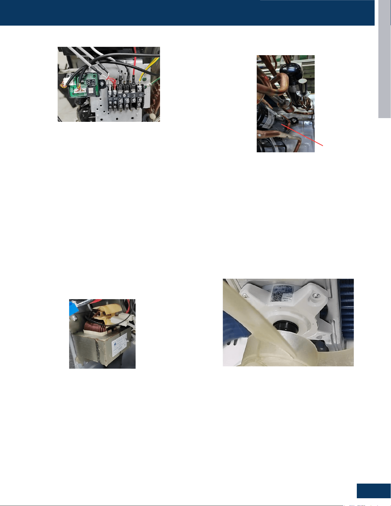
OUTDOOR UNITS
B11
ENGLISH
COMPONENTS
The Reactor is a power lter. It is unlikely to ever have an electrical
failure of this component.
The Reactor of all outdoor units is electrically connected to the IPM
on terminal connections CN-5 and CN-6.
The outdoor unit is powered by 208/230 volt single phase electricity
connected at the terminal block.
Terminals 1 and 2 connect this voltage to the system.
The number 3 terminal is communication that connects wiring
between the indoor and outdoor units. A ground terminal connects
the outdoor unit to the line voltage power source.
The indoor unit is also powered by the same electrical supply as the
outdoor unit. Only 14-4 stranded copper wire is allowed connected
to the wiring terminal block at the outdoor unit and is run to the same
terminals on the indoor terminal block.
When installing the eld supplied wiring, make certain the wire gauge
is correct. There should not be any electrical wiring splices between
the indoor unit and outdoor unit wire connection 3. This wire is
used to carry communication data between the indoor and outdoor
units. A wiring splice where wires are twisted in a wire nut may cause
deformation of the communication signal. If communication is lost
between the indoor and outdoor units, an ERROR CODE E7 will occur.
The fan motor is a variable speed motor. The required speed is
calculated by the PCB. The motor is electrically connected to the PCB
via PLUG CN-10.
In COOL MODE, the motor will slow down as outdoor air temperature
falls. In HEAT MODE, the motor will increase speed as the outdoor air
temperature falls.
The compressor is a three phase DC inverter driven rotary type,
capable of variable speed operation. The compressor operating
frequency will be determined by the temperature dierence between
set point and room temperature.
The compressor of all outdoor units is electrically connected to the
1PM on terminal connections CN-7, CN-8 and C-9.
Protection of the compressor will be provided by the discharge
temperature sensor, the suction line temperature sensor, and the
over current protection parameter in the PCB.
Terminal Block Compressor
Fan Motor
Power Factor Reactor
ENGLI SH
OUTDOOR UNITS
B-7
COMPONENTS
31-5000931 Rev. 0
ENGLI SH
OUTDOOR UNITS
B-7
COMPONENTS
31-5000931 Rev. 0
ENGLI SH
OUTDOOR UNITS
B-7
COMPONENTS
31-5000931 Rev. 0
ENGLI SH
OUTDOOR UNITS
B-7
COMPONENTS
31-5000931 Rev. 0
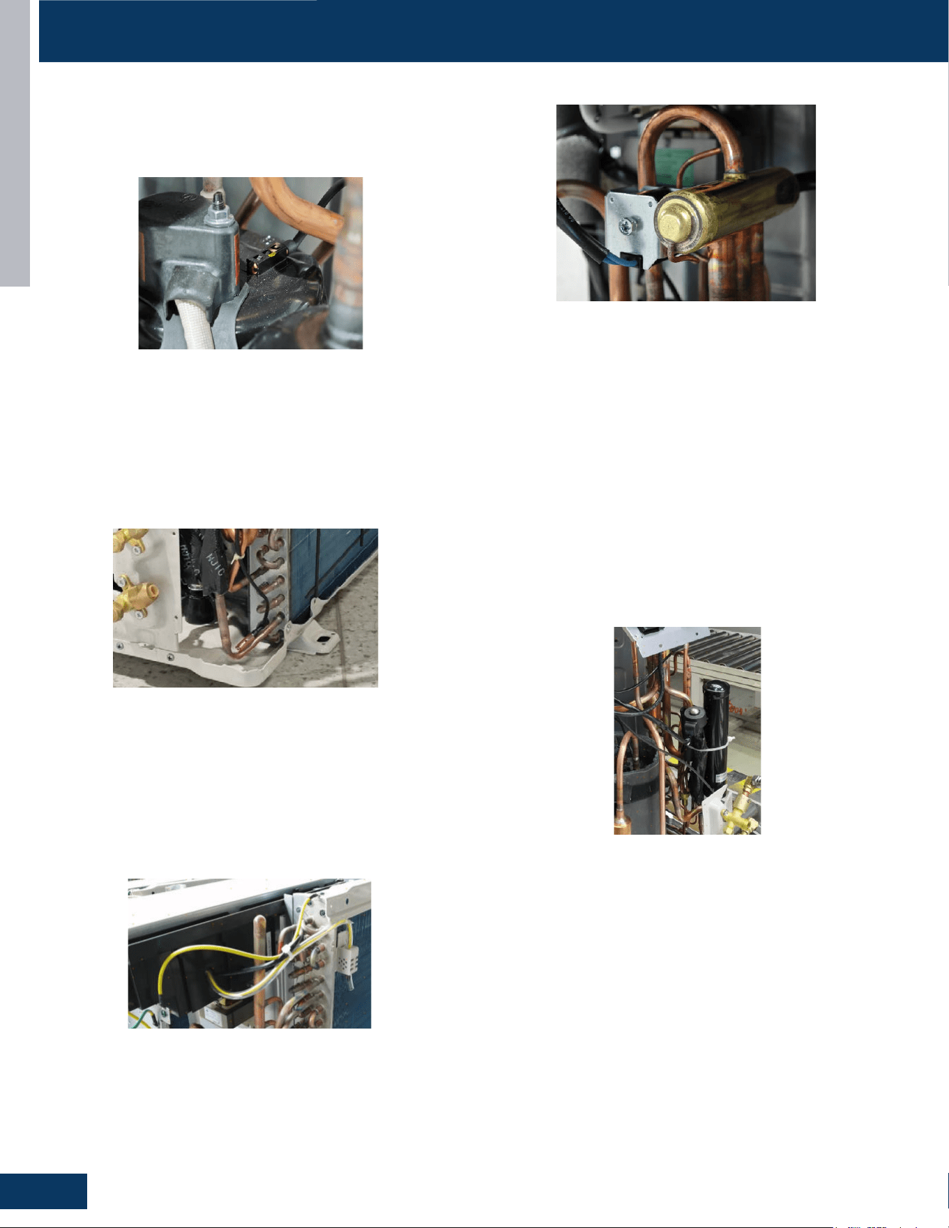
OUTDOOR UNITS
B12
ENGLISH
COMPONENTS
4-Way Valve
The 4-Way Valve redirects the ow of refrigerant in the piping circuit
to allow the system to reverse the functions of the indoor and
outdoor coils. When de-energized in COOL MODE, the valve will
direct the refrigerant hot gas to the outdoor coil. When energized in
HEAT MODE, the valve will direct the hot gas to the indoor coil.
The valve ow direction capability is controlled by an electrical
solenoid. When energized with 208/230 VAC, the solenoid will
magnetically move an internal slide within the 4-Way Valve to change
the direction of refrigerant ow.
The 4-Way Valve is electrically connected to the Main Control Board
at PLUG CN-11.
Electronic Expansion Valve
The metering device is an electronic expansion valve. The valve
consists of an electrical operator and a valve body with internal
variable size orice. When operating, the PCB will send pulses of
voltage to the electrical operator. The operator will then magnetically
move the position of the metering orice pin to vary refrigerant ow.
The metering device position is determined by input from a Suction
Line Temperature Sensor. The EEV will change the internal orice size
to maintain an acceptable level of superheat.
During COOL MODE the valve meters low pressure refrigerant to
the indoor coil. During HEAT MODE the valve meters low pressure
refrigerant to the outdoor coil.
The electrical expansion valve is electrically connected to the Main
Control Board at PLUG CN-16.
Temperature Sensors
Discharge Temperature Sensor
The Discharge Temperature Sensor is a negative coecient
thermistor that senses the temperature of the compressor hot
gas. The PCB monitors the temperature of the compressor hot gas
and will make inverter speed changes in response to input from this
device.
This sensor connects to the Main Control Board at PLUG CN-15.
Defrost Temperature Sensor
The Defrost Temperature Sensor is a negative coecient thermistor
that will change resistance in response to outdoor coil temperature
changes. The PCB monitors the temperature of the outdoor coil to
determine when the system should perform a defrost cycle. The
sensor also monitors coil temperature during defrost cycles to
determine termination conditions.
This sensor connects to the Main Control Board at PLUG CN-15.
Outdoor Ambient Temperature Sensor
The Ambient Temperature Sensor is a negative coecient
thermistor that will change resistance in response to outdoor air
temperature changes. The PCB monitors the temperature of the
outdoor air to determine fan speed requirements and inverter
speed. The sensor also plays a role in calculation of required defrost
conditions.
This sensor connects to the Main Control Board at PLUG CN-15
These 3 sensors are part of an assembly and will all be changed
together.
ENGLI SH
OUTDOOR UNITS
B-7
COMPONENTS
31-5000931 Rev. 0
ENGLI SH
OUTDOOR UNITS
B-7
COMPONENTS
31-5000931 Rev. 0
ENGLI SH
OUTDOOR UNITS
B-7
COMPONENTS
31-5000931 Rev. 0
ENGLI SH
OUTDOOR UNITS
B-7
COMPONENTS
31-5000931 Rev. 0
ENGLI SH
OUTDOOR UNITS
B-7
COMPONENTS
31-5000931 Rev. 0
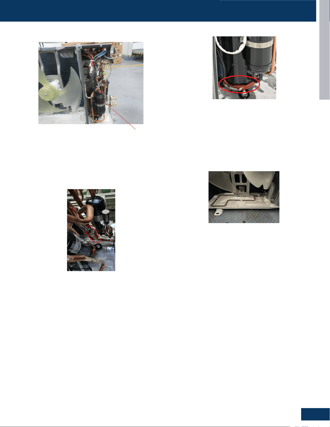
OUTDOOR UNITS
B13
ENGLISH
COMPONENTS
Accumulator
The Accumulator is located in the suction line circuit at the
entrance to the compressor. The accumulator helps prevent
liquid refrigerant from entering the compressor during run
operation.
Compressor Heater
The Compressor heater is used to preheat the compressor and assist
the start of the compressor at low temperature. The Compressor
Heater is electrically connected to the Power Control Board at PLUG
CN-13 and energized with 208/230 VAC.
Base Pan Heater
To keep condensate water from freezing inside the cabinet, a base
pan heater is installed at the base pan. The Base Pan Heater is
electrically connected to the Power Control Board at PLUG CN-12
and energized with 208/230 VAC.
Refrigerant Strainers
The system has debris-catching strainers that protect internal
system components from contaminants in the refrigerant. The
strainer is a permanent part that is not typically replaced.
ENGLI SH
OUTDOOR UNITS
B-7
COMPONENTS
31-5000931 Rev. 0
ENGLI SH
OUTDOOR UNITS
B-7
COMPONENTS
31-5000931 Rev. 0
ENGLI SH
OUTDOOR UNITS
B-7
COMPONENTS
31-5000931 Rev. 0
ENGLI SH
OUTDOOR UNITS
B-7
COMPONENTS
31-5000931 Rev. 0
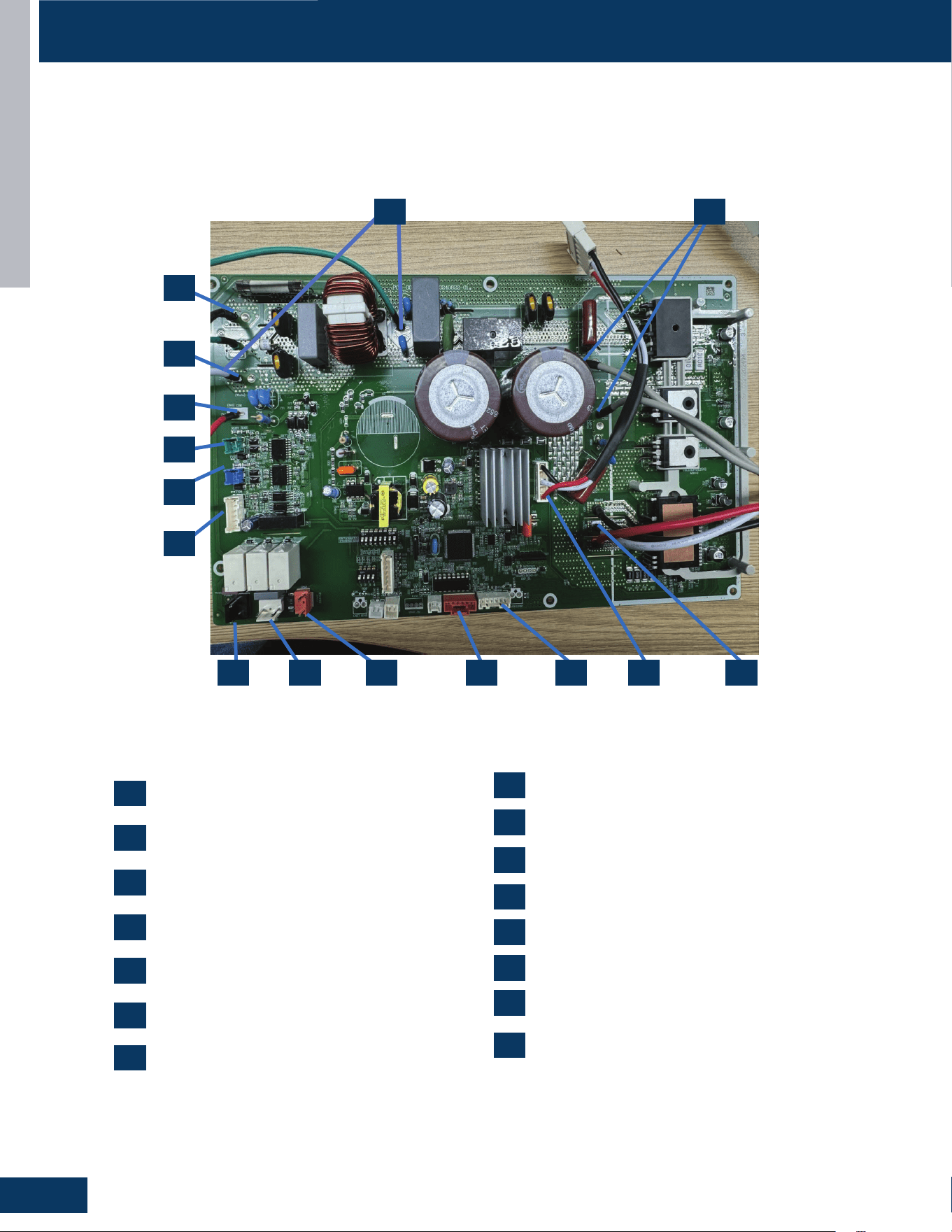
OUTDOOR UNITS
B14
ENGLISH
COMPONENTS
Outdoor Unit Control Board
CN1: 230VAC power from terminal block
connections 1(L1)
CN3,CN30: Connector for GND
CN4: Communication connection between
the indoor board and the outdoor board
CN10: Connector for the fan motor
CN7, CN8, CN9: Compressor U, V, W
connections
CN15: Connections for temperature sensors
CN16: Connector for the electronic expansion
valve
1
1
2
2
3
3
4
4
5
5
6
6
7
7
CN11: Connector for four way valve coil
CN12: Connector for the base pan heater
CN5, CN6: Connector for the reactor
CN13: Connector for the compressor heater
CN19: Connector for the RJ45
CN24: Connector for the OTA
CN14: Connector for the centralized controller
CN2: 230VAC power from terminal block
connections 2(L2)
9
9
8
8
10
10
11
11
12
12
13
13
14
14
15
15
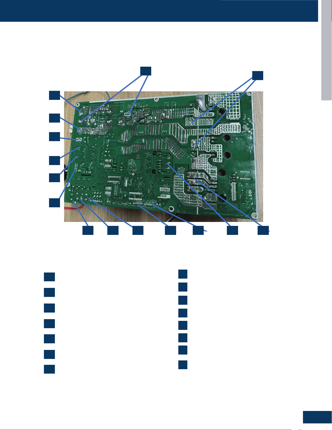
OUTDOOR UNITS
B15
ENGLISH
COMPONENTS
CN1: 230VAC power from terminal block
connections 1(L1)
CN3,CN30: Connector for GND
CN4: Communication connection between
the indoor board and the outdoor board
CN10: Connector for the fan motor
CN7, CN8, CN9: Compressor U, V, W
connections
CN15: Connections for temperature sensors
CN16: Connector for the electronic expansion
valve
1
2
3
4
5
6
7
CN11: Connector for four way valve coil
CN12: Connector for the base pan heater
CN5, CN6: Connector for the reactor
CN13: Connector for the compressor heater
CN19: Connector for the RJ45
CN24: Connector for the OTA
CN14: Connector for the centralized controller
CN2: 230VAC power from terminal block
connections 2(L2)
9
8
10
11
12
13
14
1
2
3
4 5679 8
10
11
12
13
14
15
15
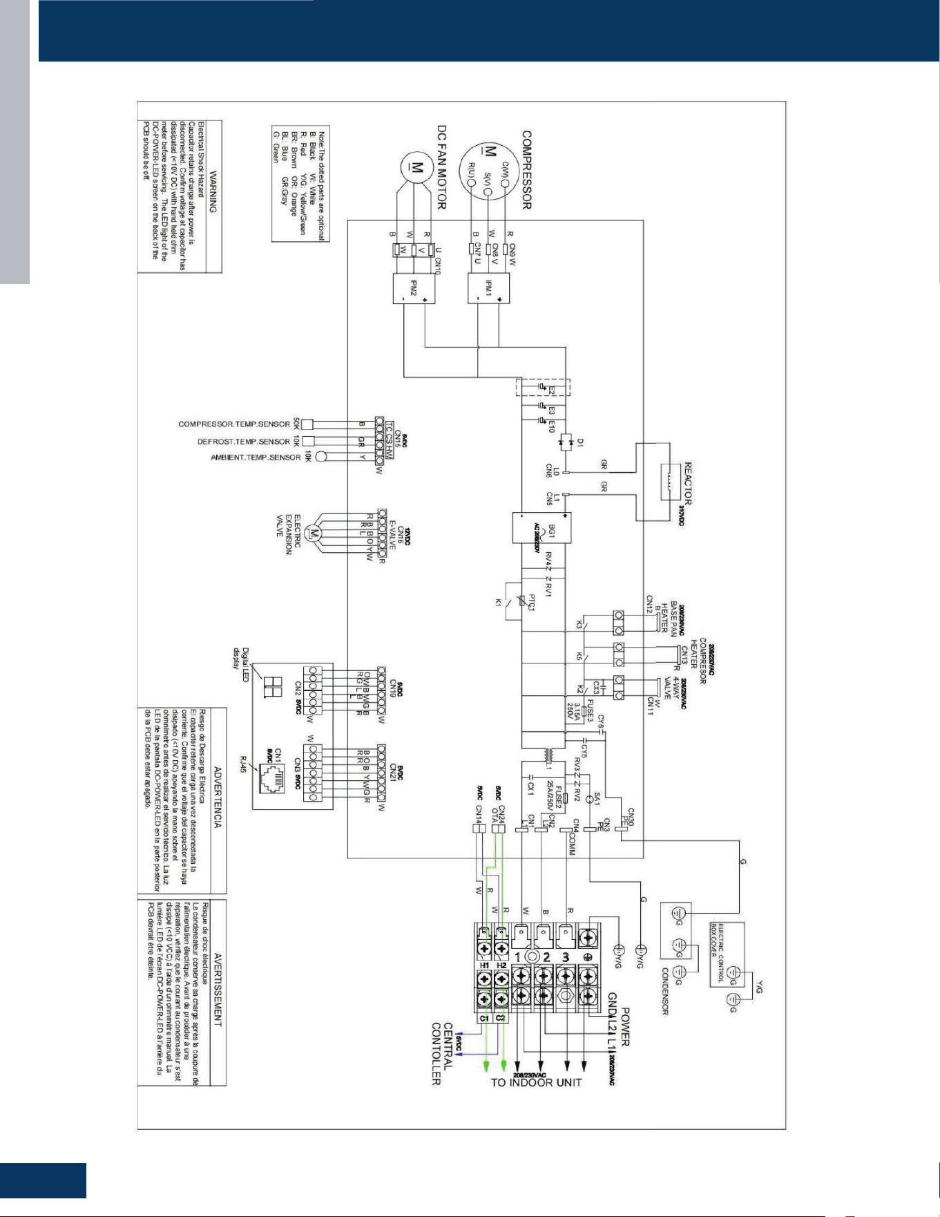
OUTDOOR UNITS
B16
ENGLISH
WIRING DIAGRAM
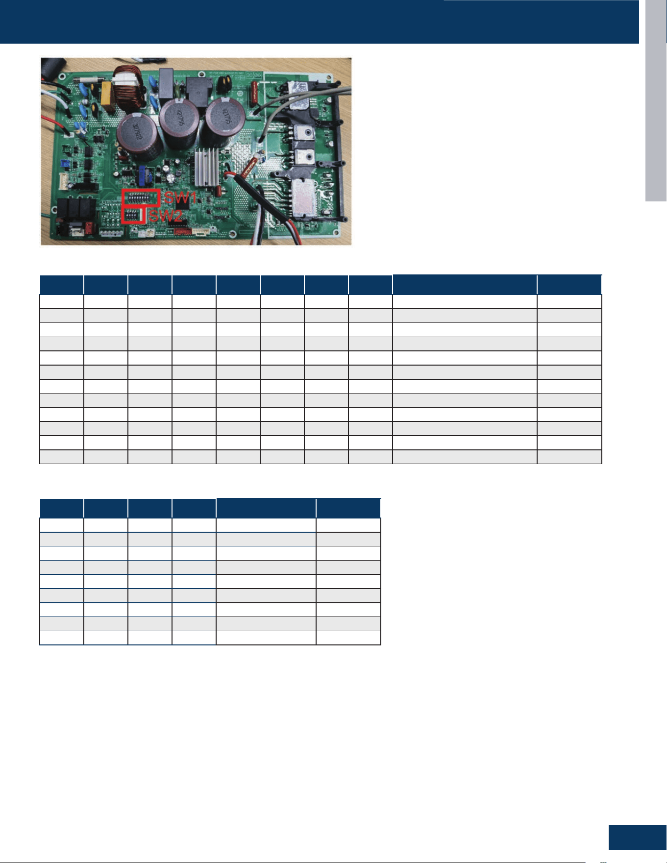
OUTDOOR UNITS
B17
ENGLISH
WIRING DIAGRAM DIP SWITCH SETTINGS
SW1-1 SW1-2 SW1-3 SW1-4 SW1-5 SW1-6 SW1-7 SW1-8 Setting Description
OFF ---- ---- ---- ---- ---- ---- ---- AC Loop Communications Default
ON ---- ---- ---- ---- ---- ---- ---- 24V Communication
---- OFF ---- ---- ---- ---- ---- ---- Central Controller Protocol Default
---- ON ---- ---- ---- ---- ---- ---- BMS Protocol
---- OFF OFF OFF OFF OFF OFF OFF Central Controller Address 1 Default
---- OFF OFF OFF OFF OFF OFF ON Central Controller Address 2
---- OFF ---- ---- ---- ---- ---- ---- --
---- OFF ON ON ON ON ON ON Central Controller Address 64
---- ON OFF OFF OFF OFF OFF OFF BMS protocol Address 1
---- ON OFF OFF OFF OFF OFF ON BMS protocol Address 2
---- ON ---- ---- ---- OFF ---- ---- --
---- ON ON ON ON ON ON ON BMS Controller Address 64
SW2-1 SW2-2 SW2-3 SW2-4 Setting Description
OFF OFF OFF OFF Endure 9K
OFF OFF OFF ON Endure 12K
OFF OFF ON OFF Endure 18K
ON OFF ON OFF Reserved
ON OFF ON ON Reserved
ON ON OFF OFF Reserved
ON ON OFF ON Reserved
ON ON ON OFF Reserved
ON ON ON ON Reserved
DIP SW1
DIP SW2
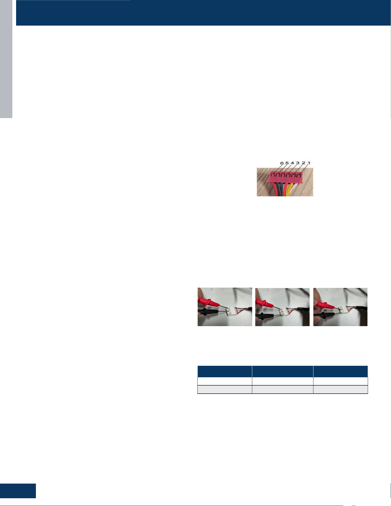
OUTDOOR UNITS
B18
ENGLISH
SERVICE PROCEDURES
NOTE: Component resistance readings shown in this section are for reference only. Actual resistance values may vary based on model being
tested.
Testing of the following components requires the use of needle probes. Avoid testing the connector end of the plug, as damage to the internal
sections of the plug can occur.
Checking the Outdoor Unit Sensors
NOTE: Use respective temperature / sensor chart for sensor type
being tested.
• Compressor discharge sensor
• Suction sensor
• Defrost temperature sensor
• Ambient sensor
Step 1
Disconnect the sensor plug from the control board for this test.
Failure to do so may provide inaccurate readings.
Step 2
Using k-type temperature probe, determine the temperature of the
sensor being tested.
Step 3
Using an ohmmeter, check the resistance value of the sensor.
Step 4
Referring to the temperature / resistance table for the sensor being
checked, verify the resistance value corresponds to the temperature
checked in Step 2. Replace the sensor if the reading is open, shorted,
or outside
Step 5
Re-seat the plug on the connector at the conclusion of the test.
Checking the EEV Coil
Step 1
Disconnect the EEV coil from the PCB for this test. Failure to do so
may provide inaccurate readings.
Step 2
Measure the resistance between 6 and 4, 6 and 2,5 and 3,5 and 1, and
the resistance,between them is roughly the same, all less than 100
Ohm.
Step 3
Re-seat the plug on the connector at the conclusion of the test.
Checking the Compressor Windings
Step 1
Disconnect wiring from terminals U, V and W of the IPM.
Step 2
Using an Ohmmeter, check the resistance value of the compressor
windings. Measure between wires U and V, U and W, and V, and W.
The resistance value of the windings should be balanced (equal
+/-20%). If the resistance values are not equal, verify the wiring and
connections to the compressor as well as the compressor itself.
Repair or replace as needed.
Step 3
Reconnect the wiring to the IPM at the conclusion of the test.
Checking the Reversing Valve Coil
Step 1
Disconnect the reversing valve plug from the PCB for this test. Failure
to do so may provide inaccurate readings.
Step 2
Using an ohmmeter, check the resistance value of the coil. The
resistance value of the coil should be 1.2 kilo ohms to 1.8 kilo ohms.
Replace the valve coil if the reading is signicantly dierent, or if the
coil shows open or shorted.
Step 3
Re-seat the plug on the connector at the conclusion of the test.
If the outdoor fan initially runs, increases speed, then stops, and the
Service Monitor Board indicates an error code of 09, the feedback
circuit is not functioning. Check that the wiring and plug connections
are in good condition.
Outdoor Fan Motor
Check that the wiring and plug connections are in good condition.
If the outdoor unit fan motor does not run, or the Service Monitor
Board indicates an error code of 09, check the following voltages at
connector CN11 on the outdoor unit PCB. Set the meter to read DC
volts with a minimum voltage range of 350 volts. All voltage values
are approximate. Initiate forced cooling.
1. DC voltage between the Red and Black wire, White and Black, and
Red and Black wire connections should read 310 ~ 334 VDC.
DC Fan Motor Value of Resistance Model
0010404886 50±8%Ω Endure 9K/12K
001040183U 30±8%Ω Endure 18K

OUTDOOR UNITS
B19
ENGLISH
SERVICE PROCEDURES
Checking the Compressor Heater
Use a multimeter to measure the resistance at both ends of the
heating wire harness terminal of the compressor. The resistance
value is 2400Ω ±5%.
Checking the Basepan Heater
Use a multimeter to measure the resistance at both ends of the
heating wire harness terminal The resistance value is 352.6Ω±5%.
Checking the Reactor
Use a multimeter to test the resistance between two terminals of a
reactor. The maximum resistance is 130mΩ.

[This page intentionally left blank.]

HIGHWALL INDOOR UNITS
C1
ENGLISH
HIGHWALL INDOOR UNITS
COMPONENTS .......................................................................................................................................................................C2
Indoor Component Identication ..........................................................................................................................................C2
Terminal Block .........................................................................................................................................................................C4
Display .....................................................................................................................................................................................C4
Ambient Temperature Sensor ...............................................................................................................................................C4
Piping Temperature Sensor ...................................................................................................................................................C4
Louver Stepper Motor ............................................................................................................................................................C5
Fan Motor ................................................................................................................................................................................C5
Emergency Button ..................................................................................................................................................................C5
Indoor Unit Control Board ......................................................................................................................................................C6
WIRING DIAGRAM ................................................................................................................................................................... C7
DIP SWITCH SETTINGS
..........................................................................................................................................................C8
SERVICE PROCEDURES
..........................................................................................................................................................C9
Checking the Stepper Motors ................................................................................................................................................C9
TABLE OF CONTENTS
GS09WB2BEA
GS12WB2BEA
GS18WB2BEA

HIGHWALL INDOOR UNITS
C2
ENGLISH
ENGLI SH
COMPONENTS
6
2
5
4
3
7
1
8
ENGLISH
COMPONENTS
6
2
5
4
3
7
1
8
Indoor Component Identication
COMPONENTS
Ambient Temperature Sensor
Display Panel
Fan Motor
Louver Motors
Power Control Board (PCB)
Piping Temperature Sensor
Terminal Block
R454B Leakage sensor
1
2
3
3
4
4
5
5
6
6
7
7
8
8
2
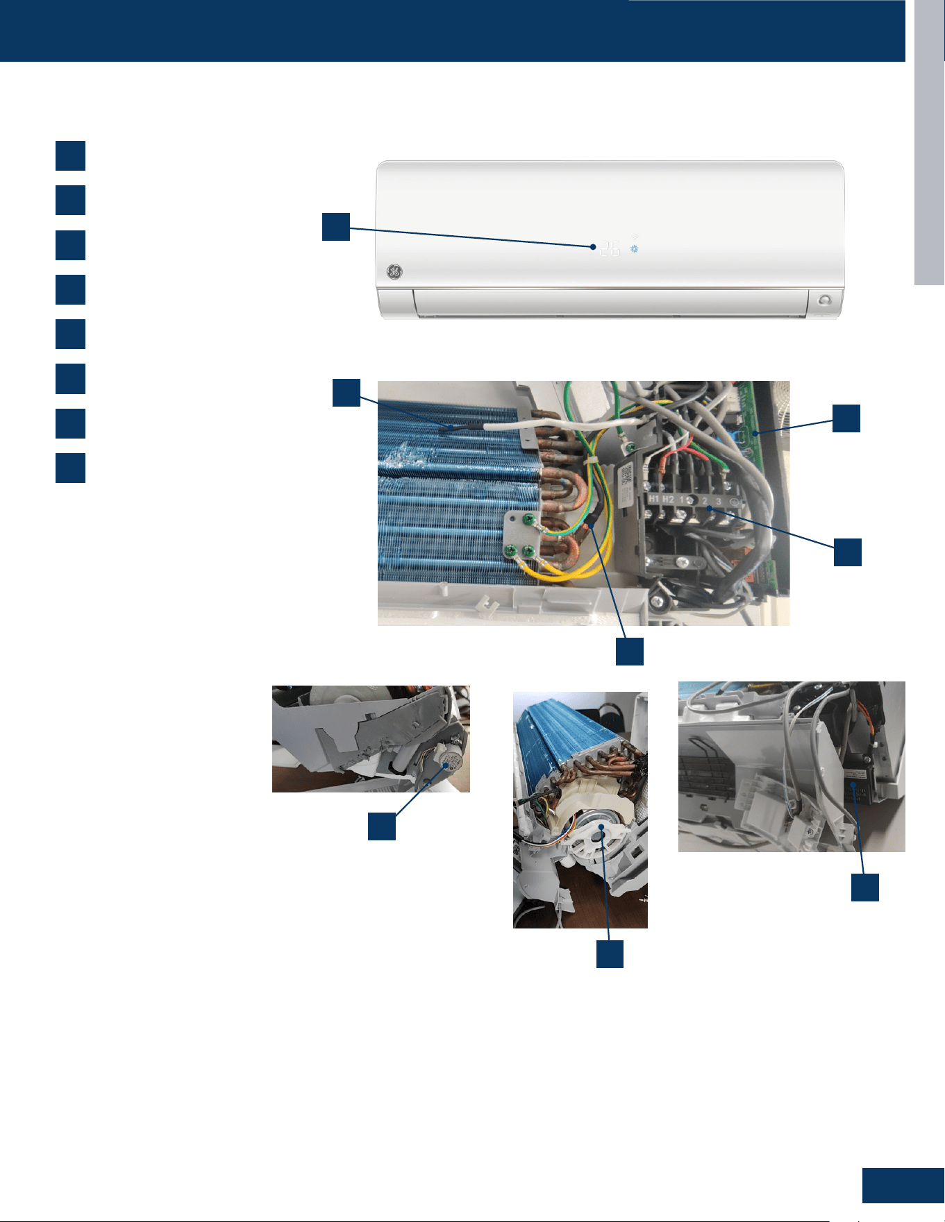
HIGHWALL INDOOR UNITS
C3
ENGLISH
COMPONENTSCOMPONENTS
Ambient Temperature Sensor
Display Panel
Fan Motor
Louver Motors
Power Control Board (PCB)
Piping Temperature Sensor
Terminal Block
R454B Leakage sensor
1
2
3
4
5
6
7
8
3
2
1
5
6
7
8
4
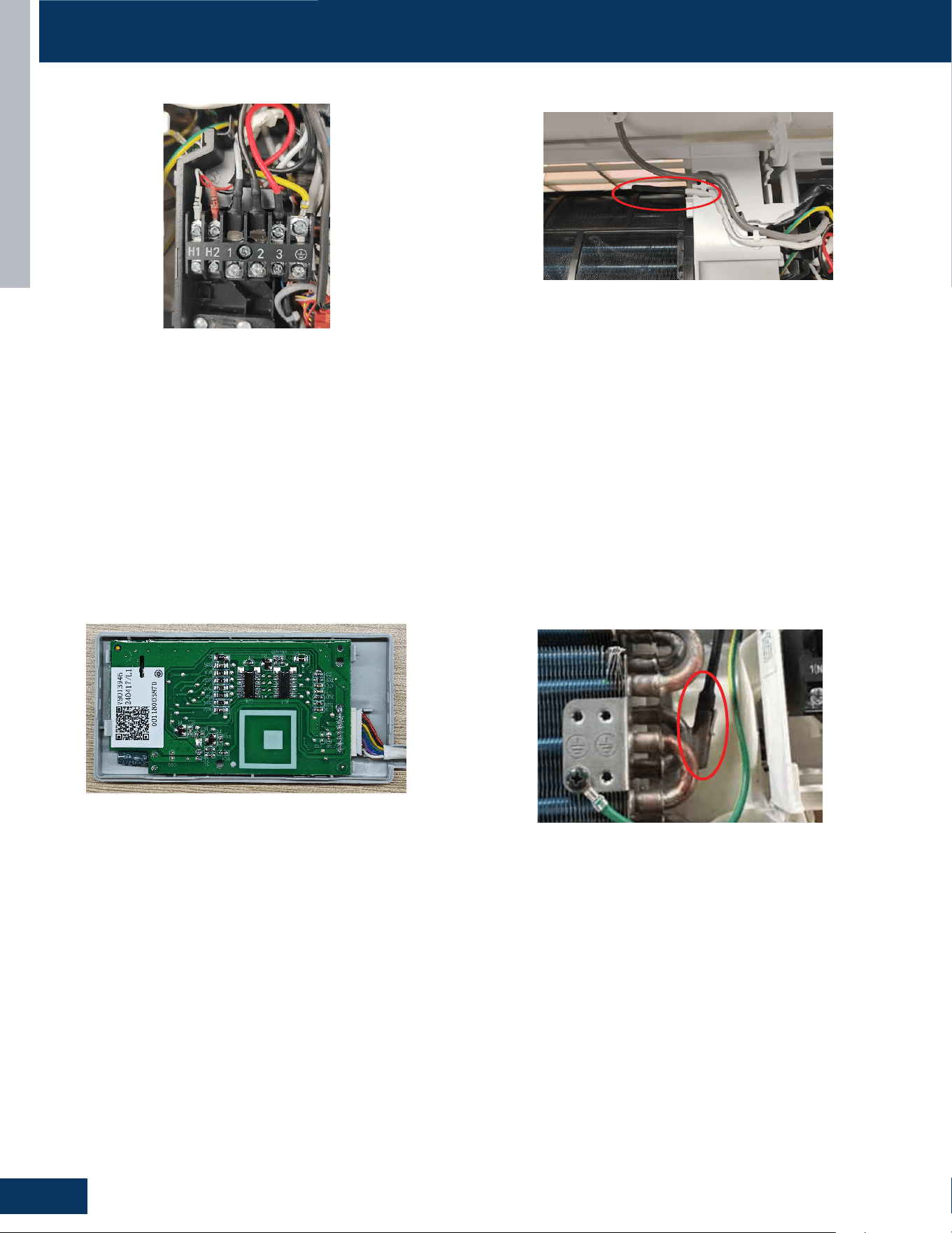
HIGHWALL INDOOR UNITS
C4
ENGLISH
Terminal Block
Ambient Temperature Sensor
The unit terminal block receives electrical power from the outdoor
unit. There are 4 connections for electrical wires. Terminals 1 and 2
are connected to terminals 1 and 2 of the outdoor unit. This wiring
supplies power to the indoor unit.
Terminal 3 is a communication wire. The indoor unit sends indoor air
temperature, coil temperature and temperature setpoint information
to the outdoor unit on this wire. If a splice or break in this wire is
present, the indoor unit will not be able to communicate with the
outdoor unit. The ERROR CODE will be an E7.
The Ambient (room) Temperature Sensor is a negative coecient
thermistor that will decrease in resistance with increases in room air
temperature. The sensor is located on a clip mounted in the return air
stream.
The sensor connects to the control board at Plug CN-6.
Piping Temperature Sensor
The Piping Temperature Sensor is a negative coecient thermistor
that will decrease in resistance with increases in coil temperature.
The sensor is located in a socket soldered to the surface of the
indoor coil.
This sensor will monitor the temperature of the indoor coil in both
cooling and heating modes of operation. Should abnormally cold or
hot coil temperature be detected by this sensor, the system will take
steps to correct the condition or report an ERROR CODE.
The sensor connects to the control board at Plug CN-6.
Display
The indoor display has an infrared communication circuit that
receives The indoor display has an infrared communication
circuit that receives operating commands from the remote
control. This display will indicate operating modes, error
codes, indoor air temperature, timer status, and power
status.
The display board connects to the control board at Plug CN-7.
COMPONENTS
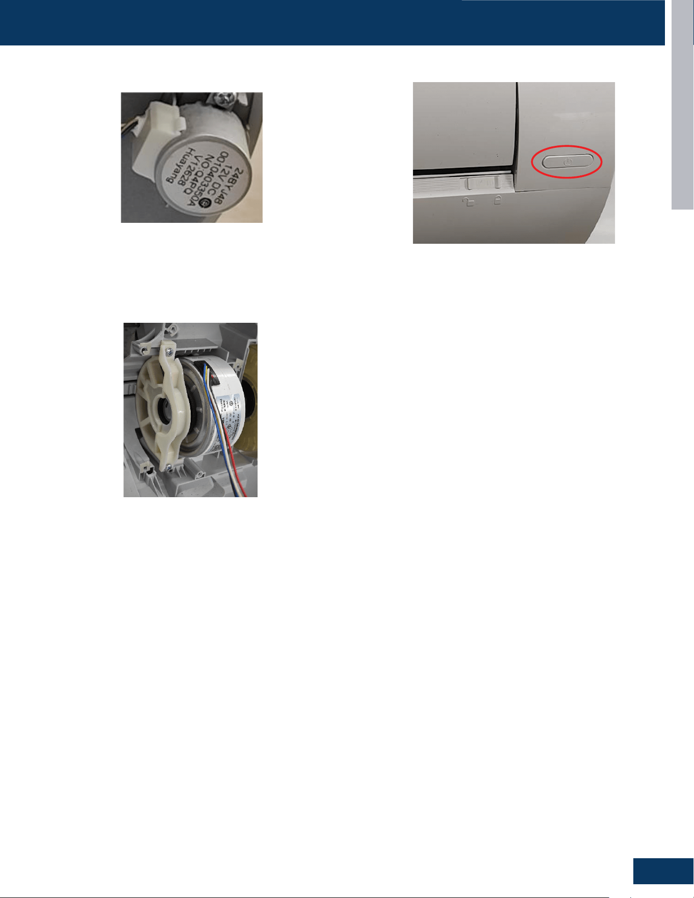
HIGHWALL INDOOR UNITS
C5
ENGLISH
Louver Stepper Motor
Fan Motor
Emergency Button
The Fan Motor is a variable speed motor. Fan speed will vary
depending upon the temperature variation from set point, or can be
set with the remote control to maintain a single set speed.
The Fan Motor is connected to the indoor control board via PLUG
CN-9.
If the remote control is non-functional, the Emergency Button can be
used. 73 -78
O
F will be maintained, until commands are received via
the remote control.
The motor moves the louver side to side depending upon selections
made at the remote control.
These motors are connected at CN-5.
COMPONENTSCOMPONENTS
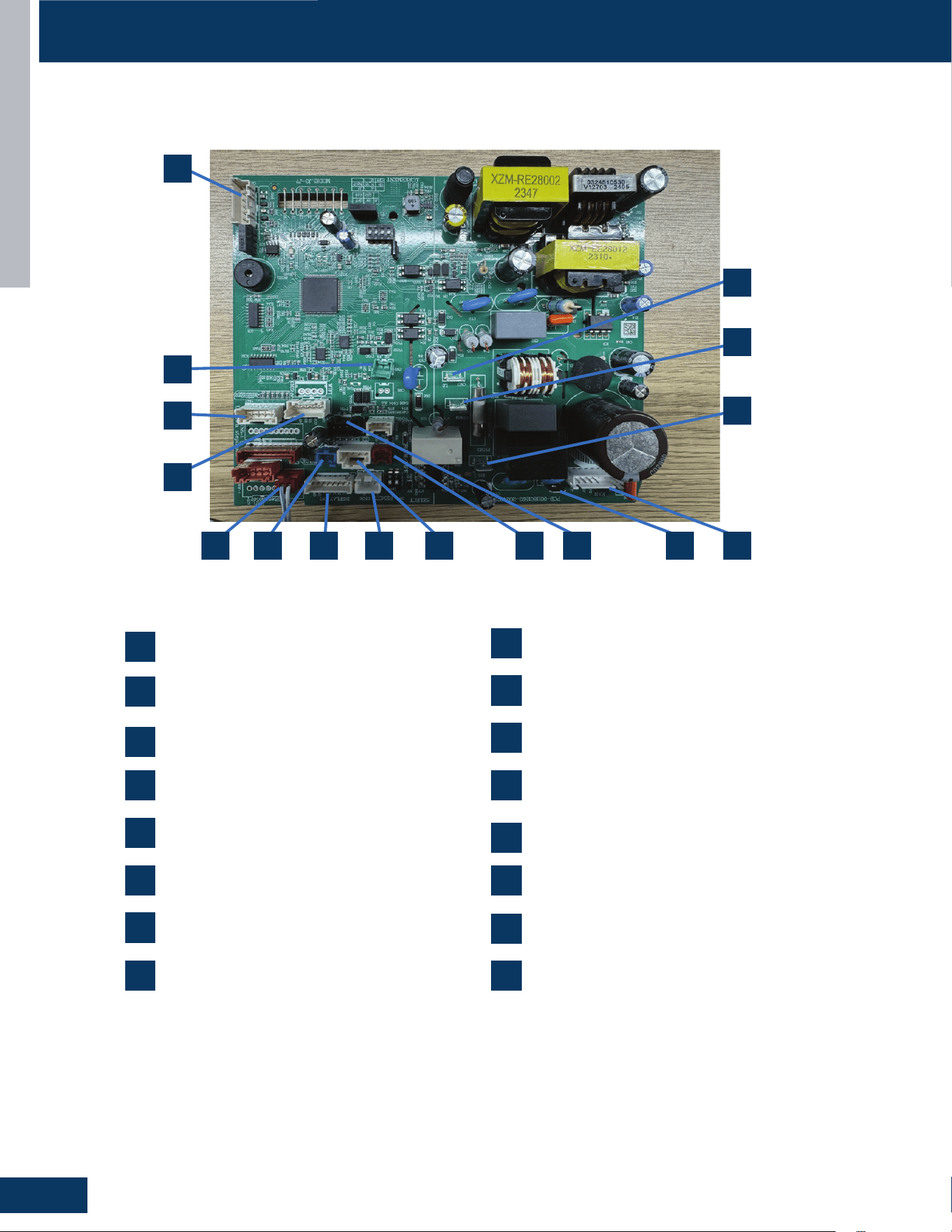
HIGHWALL INDOOR UNITS
C6
ENGLISH
COMPONENTS
Indoor Unit Control Board
13
8 11 49
14
105 2
12
3
16
67
15
1
2
CN27: Connector for GND
4
CN9: Connector for fan motor
8
CN1: Connector for non-polar wire controller
10
CN6: Connector for the temperature sensor
12
CN35: Connector for the WIFI
CN21: 208/230 AC power from terminal block
connections 1(L1)
1
CN7: Connector for the display board
7
CN14: Connector for emergency switch
5
CN3: Connector for the leakage sensor
11
CN23: Communication connection between the
indoor board and the outdoor board
3
CN51: Connector for the room cord
9
CN36: Connector for the centralized controller
6
CN5: Connector for the up-down step motor
13
14
CN2: Connector for the OTA
15
16
CN38: Connector for the RJ45
CN17: 208/230 AC power from terminal block
connections 2(L2)
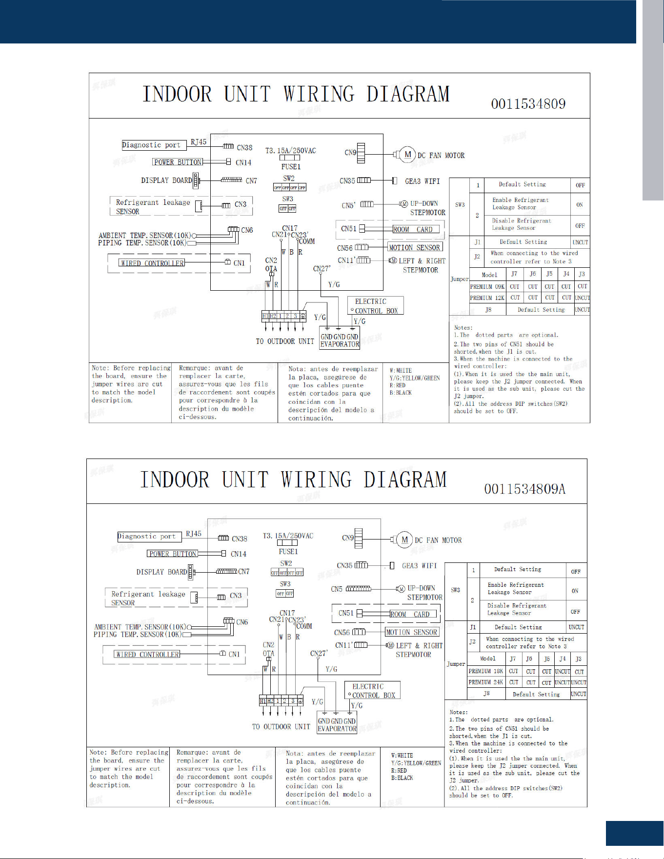
HIGHWALL INDOOR UNITS
C7
ENGLISH
WIRING DIAGRAMS
INTRODUCTION
PAGE 4
ENGLISH
IDU Wiring Diagram
GS09WP2BEA, GS12WP2BEA
GS18WP2BEA
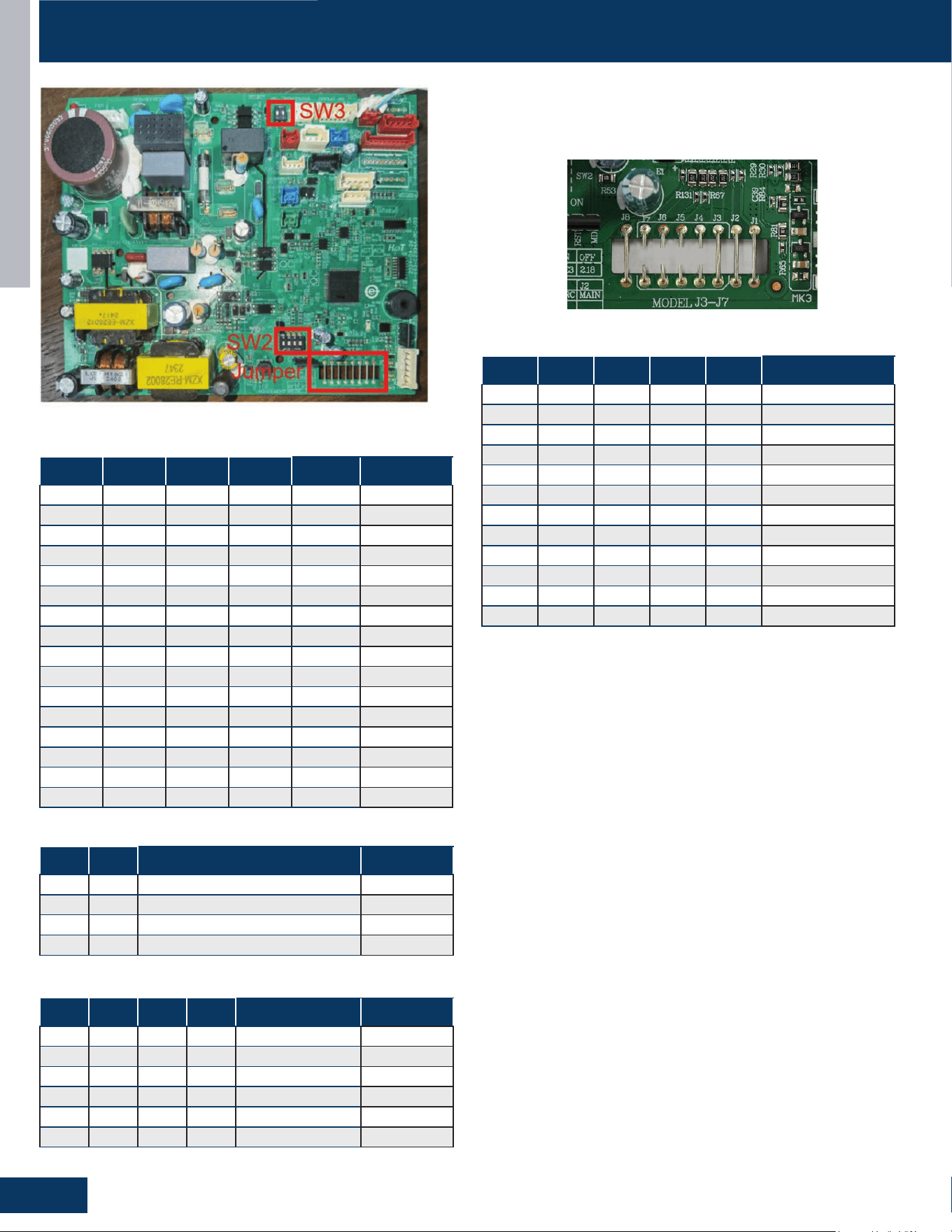
HIGHWALL INDOOR UNITS
C8
ENGLISH
DIP SWITCH & JUMPER SETTINGS
SW2-1 SW2-2 SW2-3 SW2-4 Setting Description
OFF OFF OFF OFF 0# Default
OFF OFF OFF ON 1#
OFF OFF ON OFF 2#
OFF OFF ON ON 3#
OFF ON OFF OFF 4#
OFF ON OFF ON 5#
OFF ON ON OFF 6#
OFF ON ON ON 7#
ON OFF OFF OFF 8#
ON OFF OFF ON 9#
ON OFF ON OFF 10#
ON OFF ON ON 11#
ON ON OFF OFF 12#
ON ON OFF ON 13#
ON ON ON OFF 14#
ON ON ON ON 15#
DIP SW2: Wire Controller Address
SW3-1 SW3-2 Setting Description
OFF -- Central Controller Default
ON -- 24v Controller
-- OFF Refrigerant Leak Detector Disable Default
-- ON Refrigerant Leak Detector Enable
DIP SW3
J1 J2 J8 J4 Setting Description
OFF -- -- -- Room Card Valid
ON -- -- -- Room Card Invalid Default
-- OFF -- -- Sub
-- ON -- -- Main Default
-- -- OFF -- WiFi 2.18 Protocol
-- -- ON -- WiFi GE3 Protocol Default
Jumpers J1, J2, J8
J7 J6 J5 J4 J3 Setting
OFF OFF OFF OFF OFF Endure 9K
OFF OFF OFF OFF ON Endure 12K
OFF OFF OFF ON OFF Endure 18K
OFF OFF ON OFF OFF Reserved
OFF OFF ON OFF ON Reserved
OFF ON ON ON OFF Reserved
OFF ON ON ON ON Reserved
ON OFF OFF OFF OFF Reserved
ON OFF OFF OFF ON Reserved
ON OFF OFF ON OFF Reserved
-- -- -- -- -- Reserved
ON ON ON ON ON Reserved
Jumpers J3-J7
The PCB has a set of jumper wires that must be checked when
replacing the PCB. The replacement PCB is shipped with no jumper
wires cut.

HIGHWALL INDOOR UNITS
C9
ENGLISH
SERVICE PROCEDURES
Checking the Stepper Motors
GS09WP2BEA, GS12WP2BEA
The resistance value of the relative
common terminal of the stepping motor
4 is 200 ± 7Ω
The resistance value of the relative
common terminal of the stepping motor4
is 300 ± 7Ω
GS18WP2BEA
ENGLI SH
Louver Stepper Mot or Jumper Wire Setti ngs
COMPONENTS
QS09WP2BEA、QS12WP2BEA、QS18WP2BEA
ENGLI SH
Louver Stepper Mot or Jumper Wire Setti ngs
COMPONENTS
QS09WP2BEA、QS12WP2BEA、QS18WP2BEA

[This page intentionally left blank.]

CASSETTE
D1
ENGLISH
CASSETTE
TABLE OF CONTENTS
US09CB2BEA
US12CB2BEA
US18CB2BEA
COMPONENTS .......................................................................................................................................................................D2
Indoor Component Identication ......................................................................................................................................... D2
Terminal Block ........................................................................................................................................................................ D3
Blower Motor.......................................................................................................................................................................... D3
Display ................................................................................................................................................................................. D3
Blower Assembly ................................................................................................................................................................... D3
Louver Motors ........................................................................................................................................................................ D3
Piping Temperature Sensor .................................................................................................................................................. D3
Ambient Temperature Sensor .............................................................................................................................................. D3
Control Board ......................................................................................................................................................................... D4
Condensate Pump & Float Switch ........................................................................................................................................ D4
WiFi........ ................................................................................................................................................................................. D4
Refrigerant Leakage Detector .............................................................................................................................................. D4
PCB Overview ........................................................................................................................................................................ D5
WIRING DIAGRAM ................................................................................................................................................................... D6
DIP SWITCH & JUMPER SETTINGS
.........................................................................................................................................D7
SERVICE PROCEDURES
..........................................................................................................................................................D8
Resistance Values .................................................................................................................................................................. D8
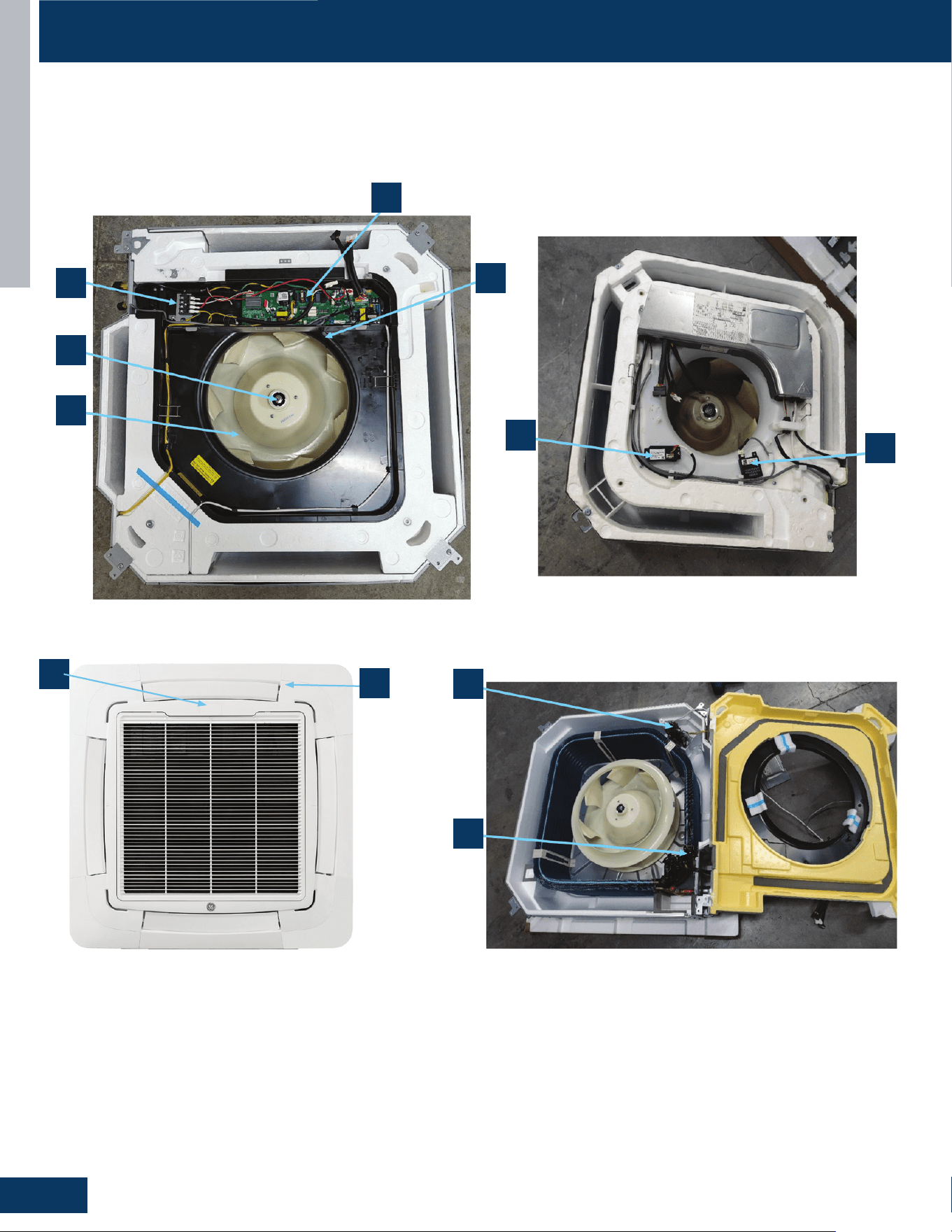
CASSETTE
D2
ENGLISH
COMPONENTS
US09CB2BEA / US12CB2BEA / US18CB2BEA / US24LB2BEA / US30LB2BEA / US36LB2BEA
1
2
4
8
7
10
11
9
6
Indoor Component Identication
3
5
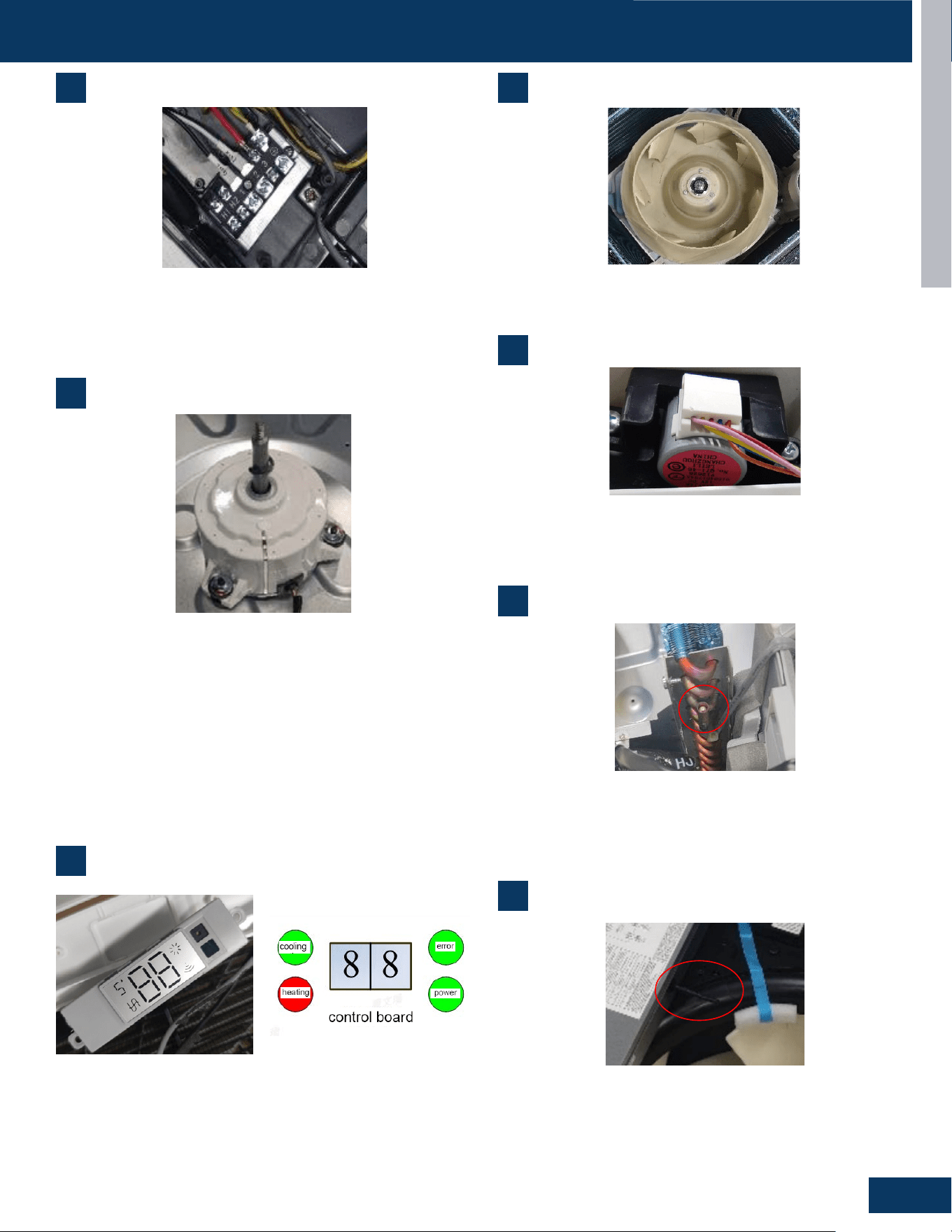
CASSETTE
D3
ENGLISH
COMPONENTS
4
5
Blower Assembly
Louver Motors
1
Terminal Block
1. Terminal Block
Power to operate the indoor unit comes from the electrical line voltage terminal block at
the outdoor unit. The wiring includes 4 wires, 1, 2, 3 and ground. Wires 1 and 3 complete
the data path. These wires should always
be
14 gauge AWG stranded cooper,
non
-
shielded
type wire. Splices in wires 1 or 3 may cause communication errors.
6
9
Power to operate the indoor unit comes from the line voltage
terminal block at the outdoor unit. The wiring includes 4 wires: 1, 2,
3 and ground. Wires 1 and 3 complete the data path. These wires
should always be 14 gauge AWG stranded cooper, non-shielded type
wire. Splices in wires 1 or 3 may cause communication errors.
The blower assembly consists of a plastic blower wheel that is
connected to a PSC indoor blower motor. A set screw holds the
blower wheel to the blower motor.
The louver motors are stepper type motors that move the louvers
up/down. The motors are controlled by pulsed voltage that cannot
be measured. If the louver does not move when it should, check for a
bind in the louvers.
2
Blower Motor
The multi-speed blower motor will change speed to match the
capacity demand from the outdoor unit. The blower motor is
controlled by both the remote control and by commands from the
outdoor unit ECU. The indoor blower motor is connected to the
indoor unit control board. The wiring from the motor to the indoor
board consists of four wire connected to pins Common, Low,
Medium, and High speeds. During normal operation, the indoor
control board will energize the indoor blower motor and request
proper speed. The motor has a run capacitor that is located in the
cassette unit’s control box. The run capacitor connects to the motor
via two orange wires. The capacitor is eld-replaceable.
2. Motor Blower
The indoor unit features a multi speed blower motor that will change speed to match
the capacity demand from the outdoor unit. Separate motors located in the indoor unit
control the operation of the motorized louvers. All of the louver motors are controlled
via commands received from the remote control. The blower motor is controlled by both
the remote control and by commands from the outdoor unit ECU.
The indoor
blower motor is a Multi Speed Fan Motor that is connected to the indoor unit control
board. The wiring from the motor to indoor board consists of 4 wires connected to pins
common, low , medium and high speeds. During normal operation, the indoor control
board will energize the indoor blower motor and request proper speed. The motor has
a run capacitor that is located in the Cassette unit
’
s control box. The run capacitor
connects to the motor via two orange wires. This capacitor is field replaceable.
The indoor unit has a display that communicates system mode. The indoor unit does not
display temperatures or diagnostic codes. When a wired controller is used, this
information is displayed on the wired controller. It is recommended to use a wired
controller with the cassette unit. When servicing a diagnostic error, ALWAYS refer to the
3. Display
outdoor unit code to make diagnostic decision
3
Display
The indoor unit has a display that communicates system mode.
The indoor unit does not display temperatures or diagnostic codes.
When a wired controller is used, this information is displayed on the
wired controller. It is recommended to use a wired controller with the
cassette unit. When servicing a diagnostic error, ALWAYS refer to the
outdoor unit code to make diagnostic decision
2. Motor Blower
The indoor unit features a multi speed blower motor that will change speed to match
the capacity demand from the outdoor unit. Separate motors located in the indoor unit
control the operation of the motorized louvers. All of the louver motors are controlled
via commands received from the remote control. The blower motor is controlled by both
the remote control and by commands from the outdoor unit ECU.
The indoor
blower motor is a Multi Speed Fan Motor that is connected to the indoor unit control
board. The wiring from the motor to indoor board consists of 4 wires connected to pins
common, low , medium and high speeds. During normal operation, the indoor control
board will energize the indoor blower motor and request proper speed. The motor has
a run capacitor that is located in the Cassette unit
’
s control box. The run capacitor
connects to the motor via two orange wires. This capacitor is field replaceable.
The indoor unit has a display that communicates system mode. The indoor unit does not
display temperatures or diagnostic codes. When a wired controller is used, this
information is displayed on the wired controller. It is recommended to use a wired
controller with the cassette unit. When servicing a diagnostic error, ALWAYS refer to the
3. Display
outdoor unit code to make diagnostic decision
4. The Blower Assembly
The blower assembly consists of a plastic blower wheel that is connected to a PSC indoor
blower motor. A set screw holds the blower wheel to the blower motor.
5. Louver Motors
The louver motors are stepper type motors that move the louvers up/down. The motors
are controlled by pulsed voltage that cannot be measured. If the louver does not move
when it should, check for a bind in the louvers.
6. Piping Temperature Sensor
The Piping Temperature Sensor senses indoor coil temperature in the cooling mode and
in the heating mode. This sensor is used for Anti Freezing and Anti Cold Blow cycles. The
sensor also provides critical temperature information to the ECU that may be used in
frequency adjustments.
7. Ambient Temperature Sensor
The Ambient Temperature Sensor senses room temperature. This sensor provides room
temperature information to the ECU for calculat
ion of inverter capacity and temperature
control. Both sensors are negative temperature coefficient type that reduce electrical
resistance as temperature rises.
8. Control Board
The indoor unit circuit board controls the switching functions of the indoor unit. All
6
Piping Temperature Sensor
The Piping Temperature Sensor senses indoor coil temperature in
the cooling mode and in the heating mode. This sensor is used for
Anti Freezing and Anti Cold Blow cycles. The sensor also provides
critical temperature information to the ECU that may be used in
frequency adjustments.
6. Piping Temperature Sensor
The Piping Temperature Sensor senses indoor coil temperature in the cooling mode and
in the heating mode. This sensor is used for Anti Freezing and Anti Cold Blow cycles. The
sensor also provides critical temperature information to the ECU that may be used in
frequency adjustments.
7. Ambient Temperature Sensor
The Ambient Temperature Sensor senses room temperature. This sensor provides room
temperature information to the ECU for calculation of inverter capacity and temperature
control. Both sensors are negative temperature coefficient type that reduce electrical
resistance as temperature rises.
8. Control Board
The indoor unit circuit board controls the switching functions of the indoor unit. All
7
Ambient Temperature Sensor
The Ambient Temperature Sensor senses room temperature.
This sensor provides room temperature information to the ECU
for calculation of inverter capacity and temperature control. Both
sensors are negative temperature coecient type that reduce
electrical resistance as temperature rises.
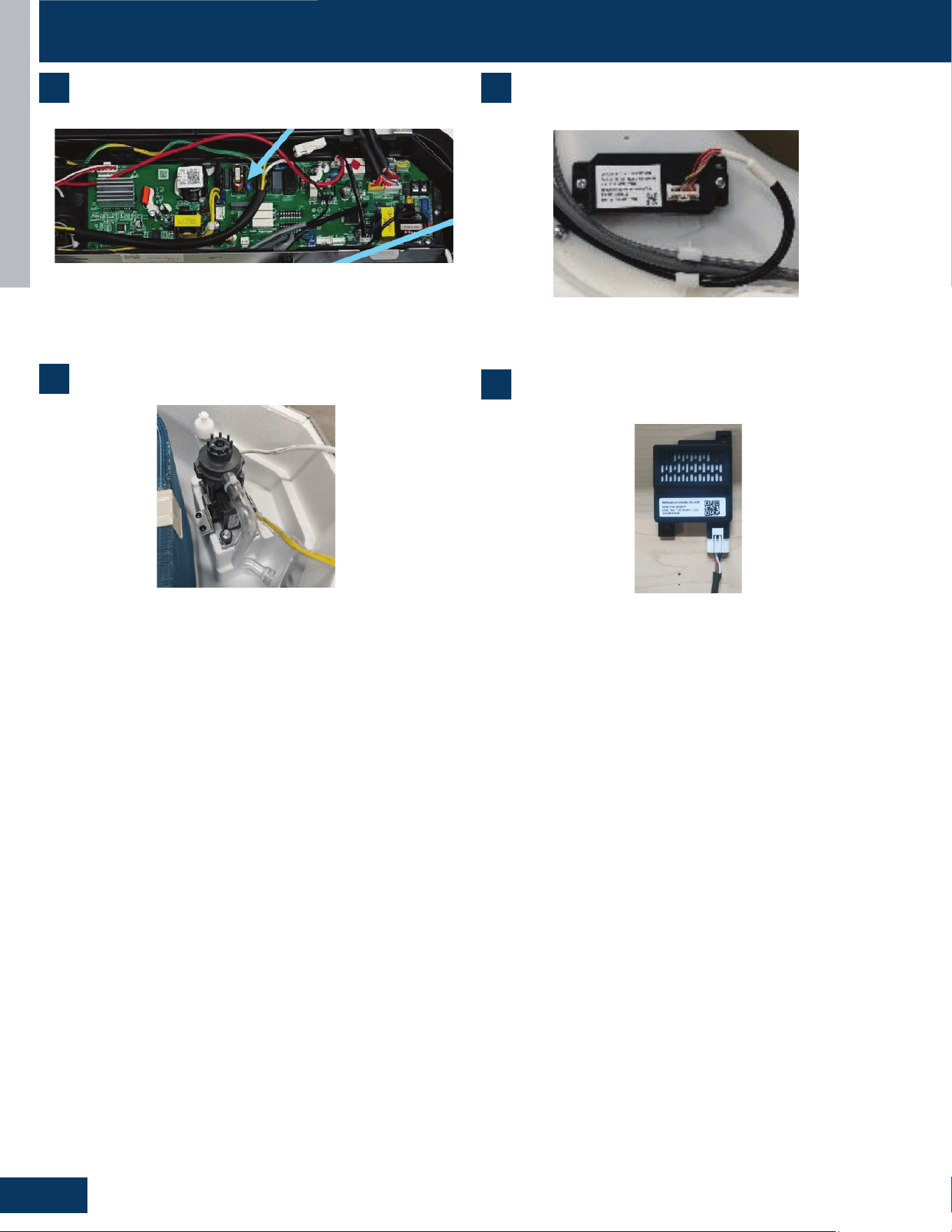
CASSETTE
D4
ENGLISH
control decisions are made by the outdoor unit ECU. The indoor board has some limited
diagnostic capability which will be covered in this manual. Condensate Pump & Float
Switch
9 Condensate Pump & Float Switch
10. Wifi
Receive and send signals, use the APP to control the air conditioning
Cooling mode (including automatic cooling operation and emergency switch setting
cooling mode) and dehumidification mode, the pump works when the compressor is on,
and the pump lags behind for 5 minutes. For other modes such as conversion heating
pump, it also continues to operate for 5 minutes according to the relevant order of the
mode.
Cooling standby, heating and fan mode, the pump does not run when the float switch is
closed. When the water tank is full, the float swit
ch is
opened,
and after the
controller detects this signal for 2 seconds, the pump starts to work. After the float
recovers, the pump continues to work with a lag of 5 minutes.
Continuous detection of water full signal for more than 5 minutes, the compressor stops
working; After the press stops, the pump continues to operate for 5 minutes. If the float
switch is still disconnected, the drainage system is reported to be faulty. After the fault,
the pump continues to operate until it is detected that the float switch is closed with a
lag of 5 minutes and the pump turns to normal operation mode.
.
8 10
9
11
Control Board WiFi
Condensate Pump & Float Switch
Refrigerant Leakage Detector
The indoor unit circuit board controls the switching functions of the
indoor unit. All control decisions are made by the outdoor unit ECU.
The indoor board has some limited diagnostic capability which will be
covered in this manual. Condensate Pump & Float Switch
Receives and sends wireless signals to enable APP control of system
operation
In cooling mode (including automatic cooling operation and
emergency switch setting cooling mode and dehumidication mode),
the pump operates when the compressor is on, and the pump 5
minutes after. For other modes such as conversion heating pump, it
also continues to operate for 5 minutes after.
Cooling standby, heating and fan mode, the pump does not run.
When the oat switch is opened, the water tank is full.
After the controller detects this signal for 2 seconds, the pump starts
to work. After the oat recovers, the pump continues to work 5 for an
additional minutes.
Continuous detection of water full signal for more than 5 minutes, will
stop the compressor. The pump continues to operate for 5 minutes.
If the oat switch is still open or disconnected, the drainage system is
reported to be faulty. After the fault, the pump continues to operate
until it is detected that the oat switch is closed or for 5 minutes.
Detects the concentration of refrigerant in the air. When the
refrigerant leakage sensor detects a concentration = 10% of lower
ammability limit, an alarm is triggered.
bA No refrigerant leakage detector is installed.
1. The sensor is not detected.
2. If the bA fault is still reported, the refrigerant sensor is abnormal.
AA LFL leakage higher than X% is detected.
1. Cut o the refrigerant, whether Ab is displayed after the
refrigerant drops. If so, the sensor is normal; If Ab is not displayed
consistently after the refrigerant concentration decreases, the
detector is abnormal and needs to be replaced.
AC Communication failure.
1. Check wiring connections. If the fault persists, replace the sensor
cable.
Ad Self-check fault.
1. The refrigerant sensor is missing (open circuit), install a new
detector.
2. Detector bypass (short circuit). Replace the detector wiring
harness. If the fault persists, replace the detector.
3. Detector output exceeds the declared range of the sensor or the
expected state is abnormal, replace the refrigerant sensor.
AE/AF Detector life warning
1. The fault is cleared after a new sensor is installed. If the fault
persists, it may be a drive board fault.
Dip Switch SW1-5:
0: Refrigerant leakage detector function valid
1: Refrigerant leakage detector function invalid
COMPONENTS
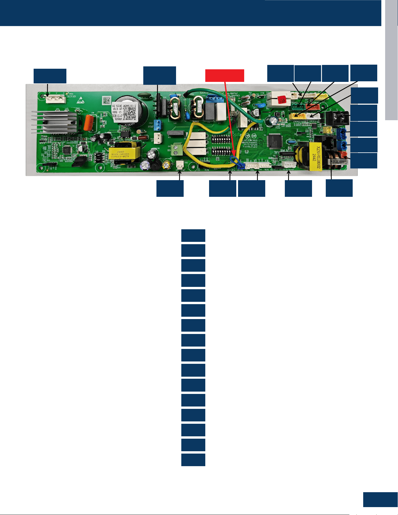
CASSETTE
D5
ENGLISH
0151800985
US09CB2BEA US12CB2BEA US18CB2BEA US24LB2BEA US30LB2BEA US36LB2BEA
CN2
CN3
CN5
CN7
CN8
CN10
CN11
CN17
CN211
CN11
CN10
CN23
CN3
CN8
CN19
CN7
CN22
CN18
CN21
CN17
CN20
CN2
CN5
CN24
CN18
CN19
CN20
CN21
CN22
CN23
CN24
CN211
COMPONENTS
PCB Overview
RJ45 Communication
Remote Control
WiFi
Sensor
Float Switch
Wired Controller
Light Board
Swing Motor
Swing Motor
AC Drain Pump
Swing Motor
Swing Motor
OTA485 Communication
Refrigerant Sensor
DC Drain Pump
Fan Motor
0151800985
CN211
CN19
CN11
CN18
CN21
CN17
CN17
CN10
CN23
CN3
CN8
CN2
CN7CN5CN22CN24
CN2
CN3
CN5
CN10
CN18
CN21
CN7
CN11
CN19
CN22
CN24
CN8
CN17
CN20
CN23
CN211
JUMPER
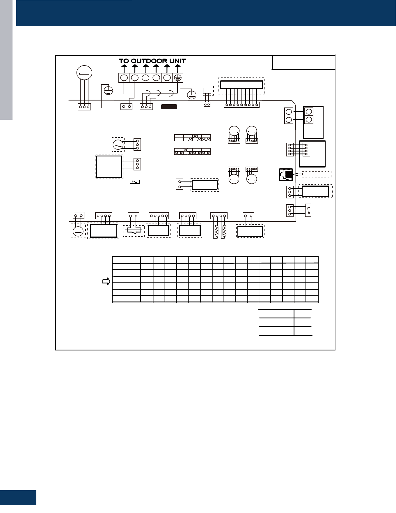
CASSETTE
D6
ENGLISH
WIRING DIAGRAM
US09CB2BEA / US12CB2BEA / US18CB2BEA
F a c t o r y de f au l t s e t t i ng
o f t he D I P s w i t c h e s
S W 1 - 1 S W 1 - 2 S W 1 - 3 S W 1 - 4 S W 1 - 6 S W 1 - 7 S W 1 - 8 S W 3 - 1 S W 3 - 2 S W 3 - 3 S W 3 - 4 S W 3 - 5 S W 3 - 6 S W 3 - 7 S W 3 - 8
US09CB2BEA
M O D E L
OFF O FF OFF O F F O F F O F F O F F O F F O F F O F F O F F O F F O F F
ON
O F F OFF O F F O F F O F F O F F O F F O F F O F F O F F O F F O F F
O F F O F F O F F O F F O F F O F F O F F O F F O F F O F F
O N
O FF
ON O N
O F F O F F O F F O F F O F F O F F O F F O F F O F F O F F
US12CB2BEA
US18CB2BEA
US24LB2BEA
US30LB2BEA
ON
OFF
OFF
O F F O F F O F F F O F F
O F
O F F O F F O F F O F F
O F F
O FF
ON
O FF
N O T E :
1 . D a s h e d
p a r t s a r e op t
i on a l .
2 . P l e a s e r e f e r t o s e r v i c e m a n ua l t o g e t d e t a i l s o f t h e D I P s w i t c he s d e f i n i t i o n .
3 . D o n o t c h ang e t h e D I P s w i t c h e s s e t t i ng w i t h o u t t e c hn i c a l s u p p o r t .
4 .G e t d e t a i l s f r o m t r ou b l e s h o o t i n g l i s t ab o u t L E D i nd i c a t i o n.
5 . A b b r e v i a t i o n
:
R D - r e d, W - w i t h e , B L K - b l a c k, B L U - b l u e , G R N - g r e e n , Y L - y e l l o w , Y / G - y e l l o w / g r ee n , E . A . O :
e x t e r n a l a l a r m o u t p u t, T r
:
i n d o o r u n i t a m b i e n t ( r oo m ) t e m p e r a t u r e s e n s o r , T p
:
i n d o o r u n i t p i p e ( c o i l )
t e m p e r a t u r e s en s o r .
6 . T he po r t C N 4 & C N 1 0 a r e d r y c o n t a c t o u t p u t po r t f o r p a r t i c u l a r u s e , do n o t c o n n e c t o t h e r d e v i ce w i t h ou t
t e c h n i c a l pe r s on s uppo r t .
US36LB2BEA
OFF OFF OFF OFF OFF OFF OFF OFF OFF OFF OFF ON ON
UVC
1 2 3
H1 H2
M
Display PCB
M
M
M M
X Y
WIRED
CONTROLLER
Y X
CN23
BLU
Air conditioning
refrigerant detector
DC Water Pump
GEA
WIFI MODULE
WIFI MODULE
Tp
Tr
DC FAN
FLOAT SWITCH
CN8
Central Controller
CN3
CN7 CN4
CN5 CN9 CN3
CN2
BLK
TO RJ45 device
Humidity Sensor
CN1 CN24
M
Room Card
M
FRELAY FOR
FRESH AIR
MOTOR(dry
Contact,rating
-230VAC,3A)/
E.A.0
AC Water Pump
FRELAY FOR
Electric Heater
CN17 CN20
YL
CN18 CN21
WH
GR RD
WH
CN19
BLU
CN15
WH
CN13
GR
CN211
WH
CN16
BLU
CN6
CN14
WH
CN11
WH
ON SW1
ON SW3
BLU
WH WH
YL
CN22
GRN
WH
BLK
RD BLU
CN10
G/Y
RD
BLK
WH
YL
YL
SWING1
M
SWING1 SWING2
SWING3 SWING4
BRN
RD
OFF
OFF ON
OFF ON
OFF ON
OFF ON
OFF ON
G/Y
Emergency
Stop
FUSE1
T6.3A 250VAC
(T8.0A 250VAC)
Possible reasons
I n do o r un i t t r ou b l e s h o o t i n g
0150577394
Wired
controller
display
07 flashing
on the upper
right corner
Outdoor error
code +20 cor-
respond HEX
code
Note:
1.To get much more details about the out door unit failure,please refer tothe outdoor unit trouble
shooting list.
2.SW1-5OFF Start the refrigerant sensor function,SW1-5ON Disable the refrigerant sensor function.
Panel
display
bA
The refrigerant det-
ector is not installed
bA
No refrigerant detector is installed
AA
AA
Refrigerant leakage
Fault “AA” cannot be cleared. Only the
leakage concentration decreases and
the fault is turned to “Ab”.See the te-
chnical manual for elimination
Ac
Ac
The communication
of the refrigerant se-
nsor is faulty
When the air conditioner is running, t-
he cable harness of the refrigerant se-
nsor falls off.
Ad
Ad
The refrigerant sens-
or self-check is faulty
The refrigerant sensor is faulty.
AE
AE
Refrigerant sensor
life threshold
Refrigerant sensor life threshold rem-
inder
AF
AF
The refrigerant sens-
or expires
Refrigerant sensor life threshold, ne-
ed to be replaced
E1
E2
E4
F1-F45
01
02
04
07
0C
E7
E8
E12
E13
E14
0D
0E
Contents of Malfun-
ction
Malfunction of indoor
unit ambient tempera-
ture sensor
Malfunction of indoor-
unit piping temperatur-
e sensor
EEPROM wrong ofin-
door PCB
Abnormal communic-
ation between indoor
and outdoor units
Abnormal communic-
ation between wiredc-
ontroller and indoor
unit
Malfunction of drain-
system
Zero cross sigal wr-
ong
Indoor unit DC fanm-
otor abnormal
Outdoor unit error
Sensor disconected,or broken,or at
wrong position,orshort circuitsor.
Sensor disconected,or braken,or at
wrong position,orshort circuit.
EEPROM chip disconectedor broken
or wrong programmed,or PCB broken.
Wrong connection,or thewires be dis-
conected or wrong adress setting of
indoorunit or faulty power supplyor fa-
ulty PCB
Wrong connection or wiredcontroller
broken,or PCB faulty.
Pump motor disconnectedor at wrong
position,or thefloat switch,disconnec-
ted,or at wrong position, or theshort
circuit bridge disconneted
Zero cross sigal detected wrong.
DC Fan motor disconnectedor DC
Fan broken or circuitbroken
See correspond Outdoorunit error tro-
uble shooting.Remark: F1 means ou-
tdoor error code 1, F2 meansoutdoor
error code 2, andso on.
Led2 flash times
tens
place
ones
place
0
1
0
0
0
0
0
0
0
2
4
7
8
12
13
14
M(≥2)
N(≥0)
18
6
17
0
17
2
17
3
17
4
17
5
SW1-5
Refrigerant Sensors
have
no
OFF
ON
G/Y
CON1
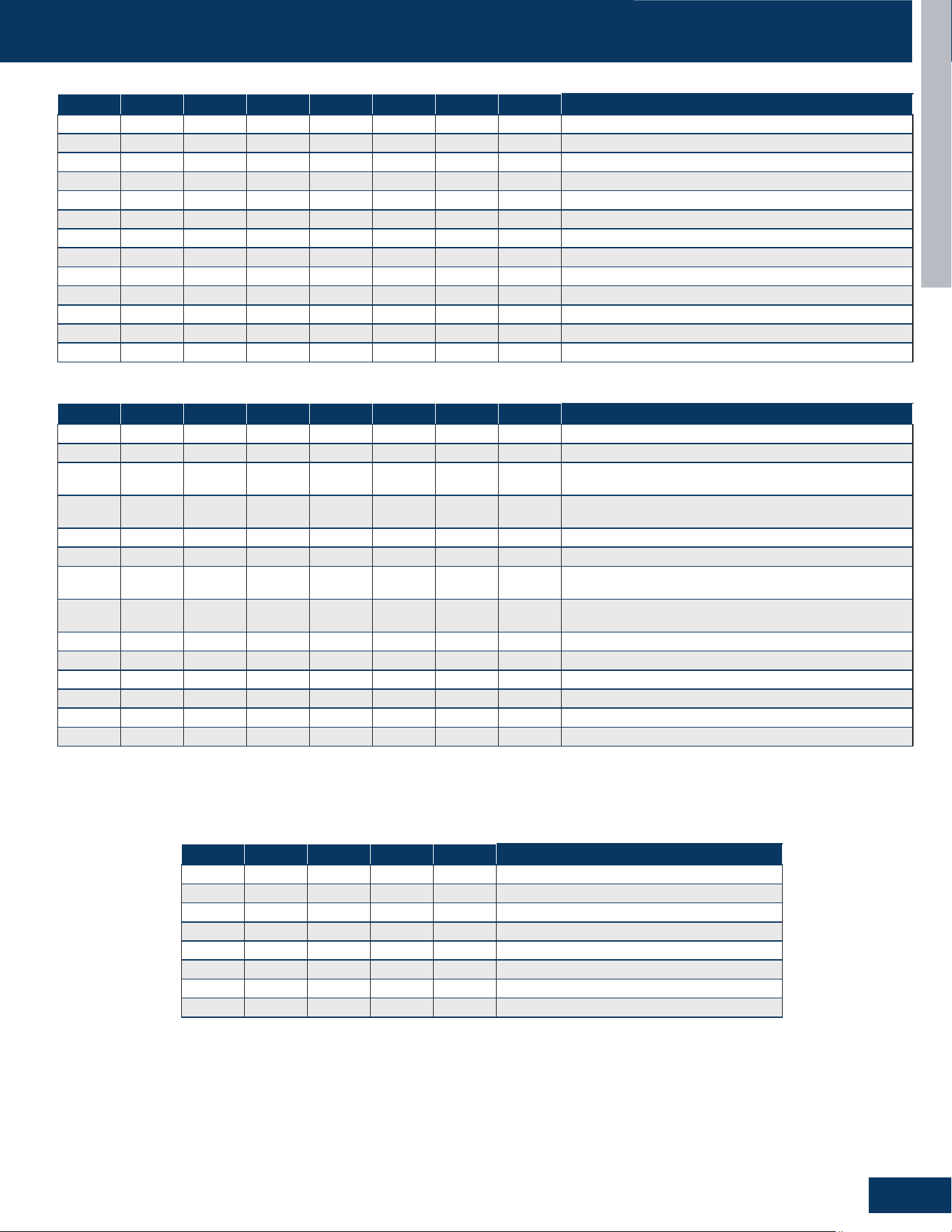
CASSETTE
D7
ENGLISH
DIP SWITCH & JUMPER SETTINGS
SW1-1 SW1-2 SW1-3 SW1-4 SW1-5 SW1-6 SW1-7 SW1-8 Description
OFF OFF OFF - - - - - 09K
ON OFF OFF - - - - - 12K
OFF ON OFF - - - - - 18K
- - - OFF - - - - Room Card Valid
- - - ON - - - - Room Card Invalid
- - - - OFF - - - Refrigerant Detector Functional
- - - - ON - - - The Refrigerant Detector Invalid
- - - - - OFF - - Fresh Air
- - - - - ON - - Fault Alarm
- - - - - - OFF - None - Filter Alarm Reminder + Refrigeration Fan Stops
- - - - - - ON - Filter Alarm Reminder + Refrigeration Fan Does Not Stop
- - - - - - - OFF Us Models
- - - - - - - ON Non-Us Models
DIP SW1
SW3-1 SW3-2 SW3-3 SW3-4 SW3-5 SW3-6 SW3-7 SW3-8 Description
OFF - - - - - - - Special Fresh Air Selection For Duct Unit: Valid
ON - - - - - - - Special Fresh Air Selection For Duct Unit: Invalid
- OFF - - - - - -
Cassette Single Swing Wind - Synchronized Swing Of
Swing Blades
- ON - - - - - -
Cassette Unit Four Swing Wind - Four Swing Blades
Swing At Dierent Angles, Misaligned Swing
- - OFF - - - - - Electrical Heating: Invalid
- - ON - - - - - Electrical Heating: Valid
- - - OFF - - - -
Model: Ultra-Slim Ducted Unit With 4-Level Static
Pressure
- - - ON - - - -
Model: Medium Static Pressure Duct With 10-Level
Static Pressure Adjustment
- - - - OFF OFF OFF OFF 0# (Wired Control Main) (Default)
- - - - OFF OFF OFF ON 1# (Line-Controlled Sub Machine)
- - - - OFF OFF ON OFF 2# (Line-Controlled Sub Machine)
- - - - OFF OFF ON ON 3# (Line-Controlled Sub Machine)
- - - - - - - - --
- - - -
ON ON ON ON 15# (Line-Controlled Sub Machine)
DIP SW3
RJ1 RJ2 RJ3 SW3-2 SW3-3 Description
OFF OFF OFF OFF OFF Crane
OFF OFF OFF OFF ON Cassette With 1 Oscillating Wind
OFF OFF OFF ON OFF Cassette With Four-Way Oscillating Wind
OFF OFF OFF ON ON Cassette With Light Panel
OFF OFF ON OFF OFF Console
OFF ON OFF OFF OFF Small Duct
OFF ON OFF OFF ON High-Capacity Duct
- - - - - Reserve
Jumper Settings - Model Identication
SW3_1 The fan selection function in cooling mode is only applicable to duct and slim duct.
SW3_4 Only applicable to slim duct
Suitable for convertible, 2HP cassette (matched with single swing wind), 2HP cassette (matched with four swing wind), 3HP cassette (equipped
with display board). For example, if the convertible has 0 0 0 0, the resistance should be welded RJ1/RJ2/RJ3. Simultaneously dial the second
digit of code BM3 to OFF and the third digit to OFF. The same setup method is used for other models.
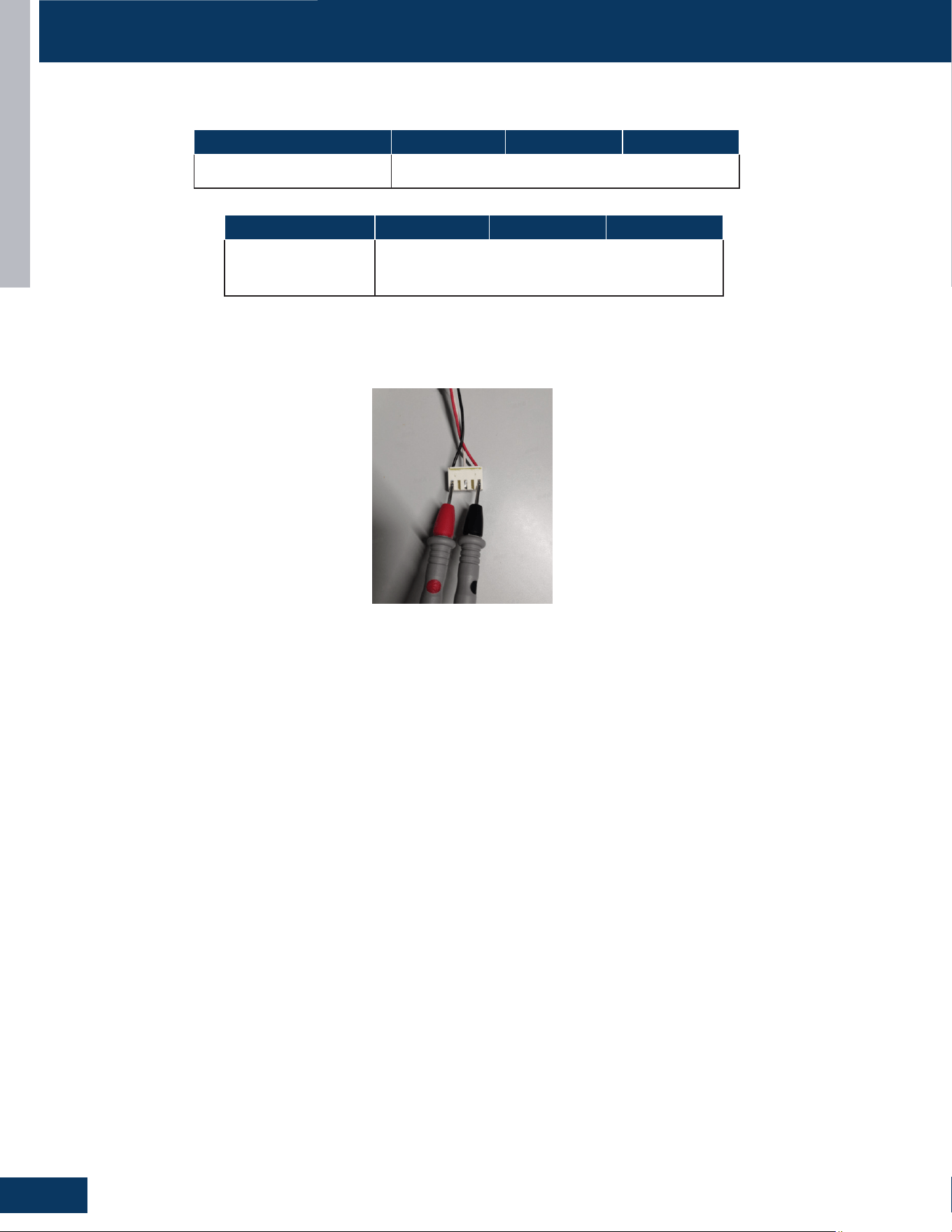
CASSETTE
D8
ENGLISH
SERVICE PROCEDURES
Resistance Values
Measure the Resistance :
Use a multimeter to measure the resistance between any two phases (U, V, W) of the motor (as shown in the following diagram).
Model US09CB2BEA US12CB2BEA US18CB2BEA
Louver Resistance
Value
0150401794A, 300Ω±7%
0150401794B, 300Ω±7%
Model US09CB2BEA US12CB2BEA US18CB2BEA
Fan Motor Resistance Value 0150401754C, 65±7%

CONSOLE
E1
ENGLISH
CONSOLE
US09FB2BEA
US12FB2BEA
US18FB2BEA
TABLE OF CONTENTS
COMPONENTS ....................................................................................................................................................................... E2
Louver Motor .......................................................................................................................................................................... E2
Flap....... ...................................................................................................................................................................................E2
Step Motor ..............................................................................................................................................................................E2
Electrical Box ...........................................................................................................................................................................E3
Pipe Bushing ............................................................................................................................................................................E3
Joint Connector ...................................................................................................................................................................... E3
Flap....... ...................................................................................................................................................................................E3
Fan Guard ................................................................................................................................................................................E3
Fan Wheel ................................................................................................................................................................................ E3
Fan Motor ................................................................................................................................................................................E3
Ambient Air Temperature Sensor ..........................................................................................................................................E3
Coil Temperature Sensor .......................................................................................................................................................E3
PCB Overview .........................................................................................................................................................................E4
WIRING DIAGRAM ................................................................................................................................................................... E5
DIP SWITCH & JUMPER SETTINGS
......................................................................................................................................... E6
SERVICE PROCEDURES
.......................................................................................................................................................... E7
Resistance Values ................................................................................................................................................................... E7
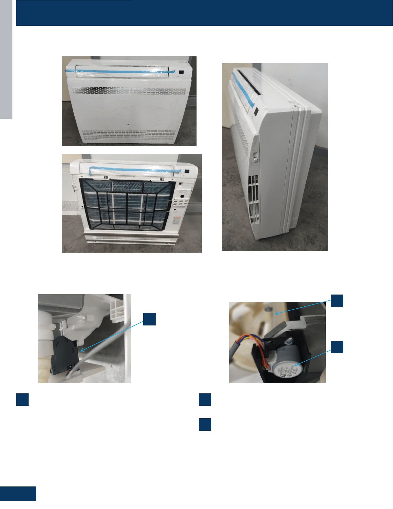
CONSOLE
E2
ENGLISH
COMPONENTS
US09FB2BEA / US12FB2BEA / US18FB2BEA
1
Louver Motor
The louver motors are stepper type motors that move the louvers
up/down. The motors are controlled by pulsed voltage that cannot
be measured. If the louver does not move when it should, check for a
bind in the louvers.
2
Flap
3
Step Motor
An electric device turning electrical pulses into precise mechanical
motions, rotating a xed angle per pulse, used for accurate control.
1
1
2
3
2
3
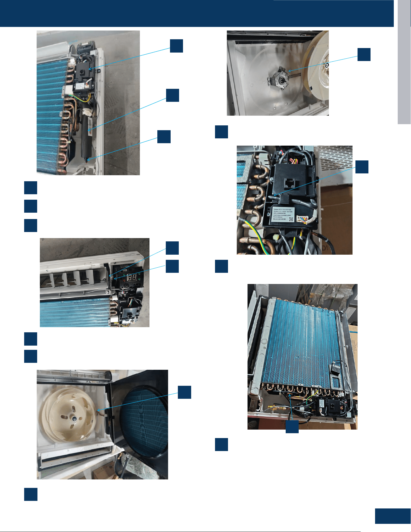
CONSOLE
E3
ENGLISH
COMPONENTS
4
Electrical Box
7
Flap
9
Fan Wheel
10
Fan Motor
11
Ambient Air Temperature Sensor
12
Coil Temperature Sensor
5
Pipe Bushing
8
Fan Guard
6
Joint Connector
4
5
6
7
8
4
5
6
7
8
11
12
9
10
13
14
11
12
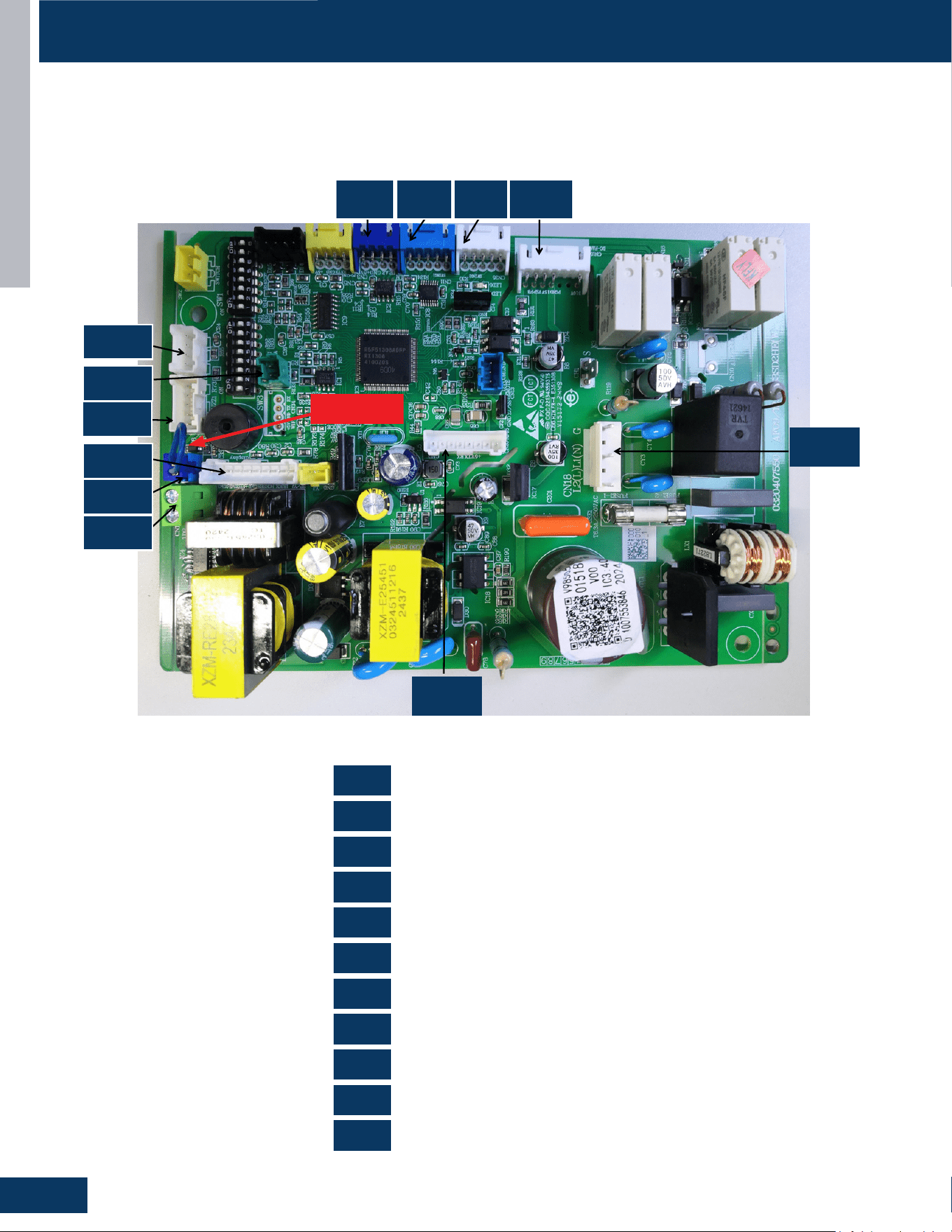
CONSOLE
E4
ENGLISH
COMPONENTS
PCB Overview
0151800987
US09FB2BEA / US12FB2BEA / US18FB2BEA
OTA
Refrigerant Sensor
Display Board
Sensor
Room Card
Left and Right Swing
Wired Controller
Fan Motor
WiFi
Power Supply
RJ45 Communication CN35 Up-and-Down Swing Motor
CN1
0151800987
US09FB2BEA US12FB2BEA US18FB2BEA
CN1
CN3
CN6
CN7
CN8
CN11
CN18
CN3
CN8
CN12
CN6
CN17
CN7
CN11
CN35
CN15
CN20
CN12
CN15
CN17
CN18
CN20
CN35
CN3 CN11 CN35 CN15
CN18
CN20
CN12
CN8
CN6
CN17
CN7
CN1
CN1
CN8
CN6
CN12
CN18
CN3
CN11
CN17
CN7
CN15
CN20
JUMPER
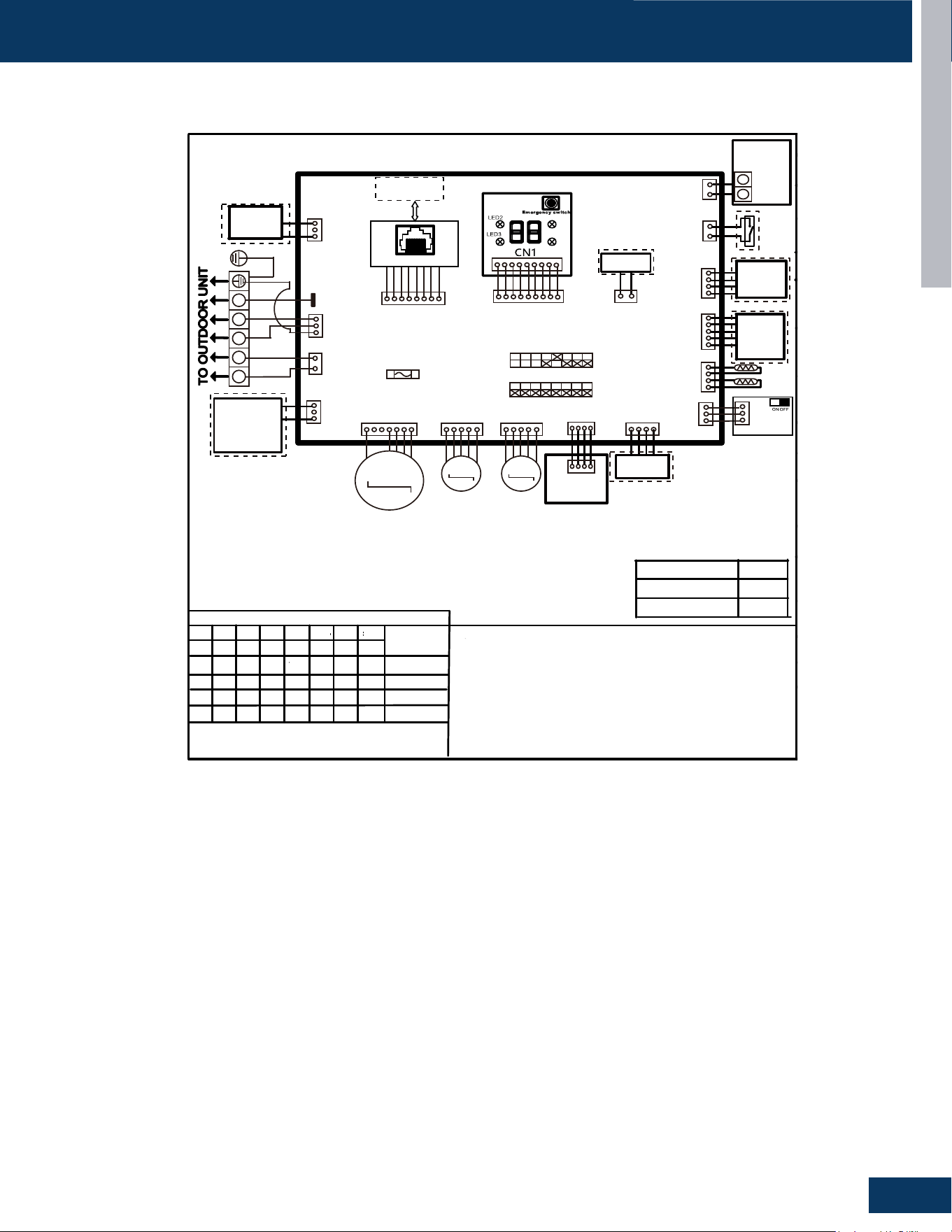
CONSOLE
E5
ENGLISH
WIRING DIAGRAM
US09FB2BEA / US12FB2BEA / US18FB2BEA
US09FB2BEA
Note :
1.Dashed parts are optional.
2.Please refer to the technical service manual for detailed explanations
of DI P switches.
3.Do not change the DI P switches setting without technical support
4.Abbreviation : R-red ,B-black,BL-blue, W -white,Y/G-yellow/green,
TEM P .-temperature, E.A.O-exrernal alarm output, T r-indoor unit
room temperature sensor ,Tp-indoor unit pipe temperature sensor (coil
temperature sensor)
W i r ed cont r oller
display(YR-E17)
07 flashing on the
upper right corner
Outdoor error code
+20 correspond HEX
code
SW1-1
OFF
OFF
SW1-2
OFF
OFF
OFF
OFF
OFF
OFF
OFF
OFF
OFF
OFF
OFF
ON
OFF
OFF
OFF
OFF
OFF OFF
ON
SW1-3
SW1-4
SW1-5 SW1-6
SW1-7 SW1-8
All Console
default
MODEL
DI P switches factory default setting
Note:
1.To get much more details about the out door unit failure,please refer tothe outdoor unit trouble
shooting list.
2.SW1-5OFF Start the refrigerant sensor function,SW1-5ON Disable the refrigerant sensor function
P anel
display
SW3-1
SW3-2 SW3-3
SW3-4
SW3-5 SW3-6
SW3-7 SW3-8
US12FB2BEA
US18FB2BEA
1 2 3
1 H 2 H
RD
BLK
WH
8 1 N C
H W
1 H C
1 N C
N R G
FRELAY FOR
FRESH AIR
MOTOR(dry
Contact,rating
-230VAC,3A)/
E.A.0
0 1 N C
H W
CN15
WH
M
DC FAN
CN35
WH
CN11
BLU
M
M
SWING2 SWING1
CN3
BLU
Air conditioning
refrigerant detector
Humidit y
Senso r
CN14
BLK
2 W S
L Y
T p
T r
7 N C
H W
I F I W A E G
E L U D O M
7 1 N C
H W
I F I W
E L U D O M
4 3 N C
H W
8 N C
m o o R
d r a C
U L B
UPPER/LOWER
OUTLET LOUVER
SELECTION SWITCH
BOARD
Centra l
Controlle r
3 1 N C
U L B
CN20
WH
RJ45 BOARD
T o RJ45 DEVICE
D E R I W
R E L L O R T N O C
Y
X
2 1 N C
N R G
1 W S
5 D E L
4 D E L
CN6
WH
DISPLAY BOARD
SW4
YL
Emergency
Stop
FUSE1
T6.3A/250VAC
Main cont r ol boa r d
BRN
RD
Y/G
Y/G
0150577395
OFF
OFF
OFF
ON SW1
ON SW3
bA
The refrigerant det-
ector is not installed
bA
No refrigerant detector is installed
AA
AA
Refrigerant leakage
Fault “AA” cannot be cleared. Only the
leakage concentration decreases and
the fault is turned to “Ab”.See the te-
chnical manual for elimination
Ac
Ac
The communication
of the refrigerant se-
nsor is faulty
When the air conditioner is running, t-
he cable harness of the refrigerant se-
nsor falls off.
Ad
Ad
The refrigerant sens-
or self-check is faulty
The refrigerant sensor is faulty.
AE
AE
Refrigerant sensor
life threshold
Refrigerant sensor life threshold rem-
inder
AF
AF
The refrigerant sens-
or expires
Refrigerant sensor life threshold, ne-
ed to be replaced
E1
E2
E4
F1-F45
01
02
04
07
0C
E7
E8
E12
E13
E14
0D
0E
Contents of Malfun-
ction
Malfunction of indoor
unit ambient tempera-
ture sensor
Malfunction of indoor-
unit piping temperatur-
e sensor
EEPROM wrong ofin-
door PCB
Abnormal communic-
ation between indoor
and outdoor units
Abnormal communic-
ation between wiredc-
ontroller and indoor
unit
Malfunction of drain-
system
Zero cross sigal wr-
ong
Indoor unit DC fanm-
otor abnormal
Outdoor unit error
Sensor disconected,or broken,or at
wrong position,orshort circuitsor.
Sensor disconected,or braken,or at
wrong position,orshort circuit.
EEPROM chip disconectedor broken
or wrong programmed,or PCB broken.
Wrong connection,or thewires be dis-
conected or wrong adress setting of
indoorunit or faulty power supplyor fa-
ulty PCB
Wrong connection or wiredcontroller
broken,or PCB faulty.
Pump motor disconnectedor at wrong
position,or thefloat switch,disconnec-
ted,or at wrong position, or theshort
circuit bridge disconneted
Zero cross sigal detected wrong.
DC Fan motor disconnectedor DC
Fan broken or circuitbroken
See correspond Outdoorunit error tro-
uble shooting.Remark: F1 means ou-
tdoor error code 1, F2 meansoutdoor
error code 2, andso on.
Possible reasons
OFF
OFF
OFF
OFF OFF OFF
OFF
OFF
1 N C
H W
SW1-5
Refrigerant Sensors
have
no
OFF
ON
CONSOLE
E6
ENGLISH
DIP SWITCH & JUMPER SETTINGS
SW1-1 SW1-2 SW1-3 SW1-4 SW1-5 SW1-6 SW1-7 SW1-8 Description
OFF OFF OFF - - - - - 09K
ON OFF OFF - - - - - 12K
OFF ON OFF - - - - - 18K
- - - OFF - - - - Room Card Valid
- - - ON - - - - Room Card Invalid
- - - - OFF - - - Refrigerant Detector Functional
- - - - ON - - - The Refrigerant Detector Invalid
- - - - - OFF - - Fresh Air
- - - - - ON - - Fault Alarm
- - - - - - OFF - None - Filter Alarm Reminder + Refrigeration Fan Stops
- - - - - - ON - Filter Alarm Reminder + Refrigeration Fan Does Not Stop
- - - - - - - OFF Us Models
- - - - - - - ON Non-Us Models
DIP SW1
SW3-1 SW3-2 SW3-3 SW3-4 SW3-5 SW3-6 SW3-7 SW3-8 Description
OFF - - - - - - - Special Fresh Air Selection For Duct Unit: Valid
ON - - - - - - - Special Fresh Air Selection For Duct Unit: Invalid
- OFF - - - - - -
Cassette Single Swing Wind - Synchronized Swing Of
Swing Blades
- ON - - - - - -
Cassette Unit Four Swing Wind - Four Swing Blades
Swing At Dierent Angles, Misaligned Swing
- - OFF - - - - - Electrical Heating: Invalid
- - ON - - - - - Electrical Heating: Valid
- - - OFF - - - -
Model: Ultra-Slim Ducted Unit With 4-Level Static
Pressure
- - - ON - - - -
Model: Medium Static Pressure Duct With 10-Level
Static Pressure Adjustment
- - - - OFF OFF OFF OFF 0# (Wired Control Main) (Default)
- - - - OFF OFF OFF ON 1# (Line-Controlled Sub Machine)
- - - - OFF OFF ON OFF 2# (Line-Controlled Sub Machine)
- - - - OFF OFF ON ON 3# (Line-Controlled Sub Machine)
- - - - - - - - --
- - - -
ON ON ON ON 15# (Line-Controlled Sub Machine)
DIP SW3
RJ1 RJ2 RJ3 SW3-2 SW3-3 Description
OFF OFF OFF OFF OFF Crane
OFF OFF OFF OFF ON Cassette With 1 Oscillating Wind
OFF OFF OFF ON OFF Cassette With Four-Way Oscillating Wind
OFF OFF OFF ON ON Cassette With Light Panel
OFF OFF ON OFF OFF Console
OFF ON OFF OFF OFF Small Duct
OFF ON OFF OFF ON High-Capacity Duct
- - - - - Reserve
Jumper Settings - Model Identication
SW3_1 The fan selection function in cooling mode is only applicable to duct and slim duct.
SW3_4 Only applicable to slim duct
Suitable for convertible, 2HP cassette (matched with single swing wind), 2HP cassette (matched with four swing wind), 3HP cassette (equipped
with display board). For example, if the convertible has 0 0 0 0, the resistance should be welded RJ1/RJ2/RJ3. Simultaneously dial the second
digit of code BM3 to OFF and the third digit to OFF. The same setup method is used for other models.
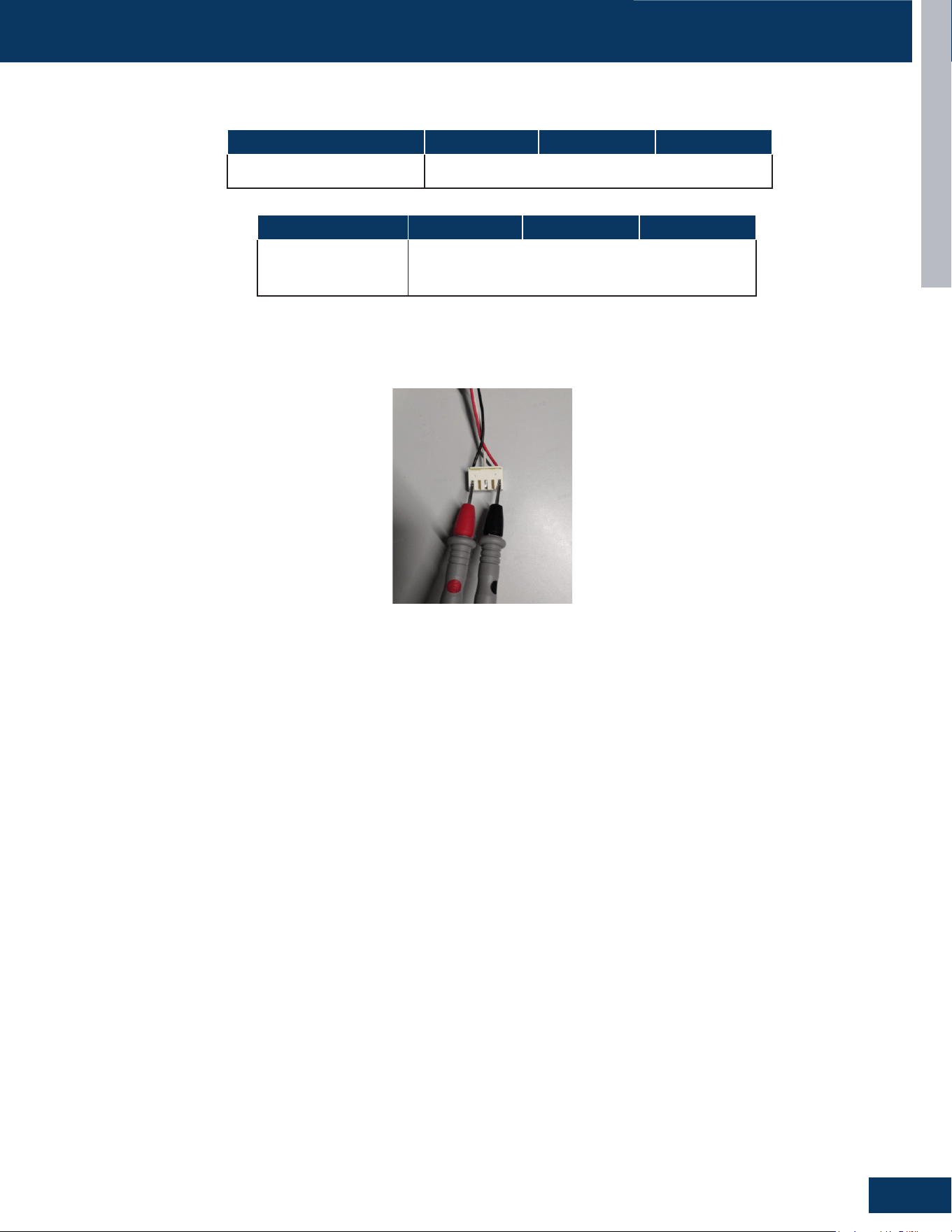
CONSOLE
E7
ENGLISH
SERVICE PROCEDURES
Measure the Resistance :
Use a multimeter to measure the resistance between any two phases (U, V, W) of the motor (as shown in the following diagram).
Model US09FB2BEA US12FB2BEA US18FB2BEA
Louver Resistance
Value
0010402433KA, 300Ω±7%
Model US09FB2BEA US12FB2BEA US18FB2BEA
Fan Motor Resistance Value 0150402538, 107Ω±10%
Resistance Values
DIP SWITCH & JUMPER SETTINGS

[This page left intentionally blank]

MID-STATIC DUCTED
F1
ENGLISH
MID-STATIC DUCTED
US09MB2BEA
US12MB2BEA
US18MB2BEA
TABLE OF CONTENTS
COMPONENTS ....................................................................................................................................................................... F2
Evaporator Coil ....................................................................................................................................................................... F2
Blower Assembly .................................................................................................................................................................... F2
3 Terminal Block ...................................................................................................................................................................... F2
Control Board .......................................................................................................................................................................... F2
Ambient Temperature Sensor ............................................................................................................................................... F2
Piping Temperature Sensor ................................................................................................................................................... F2
Condensate Pump .................................................................................................................................................................. F3
Gravity Drain Ports ................................................................................................................................................................. F3
PCB Overview ......................................................................................................................................................................... F3
WIRING DIAGRAM ................................................................................................................................................................... F4
DIP SWITCH & JUMPER SETTINGS
......................................................................................................................................... F5
SERVICE PROCEDURES
.......................................................................................................................................................... F6
Resistance Values ................................................................................................................................................................... F6
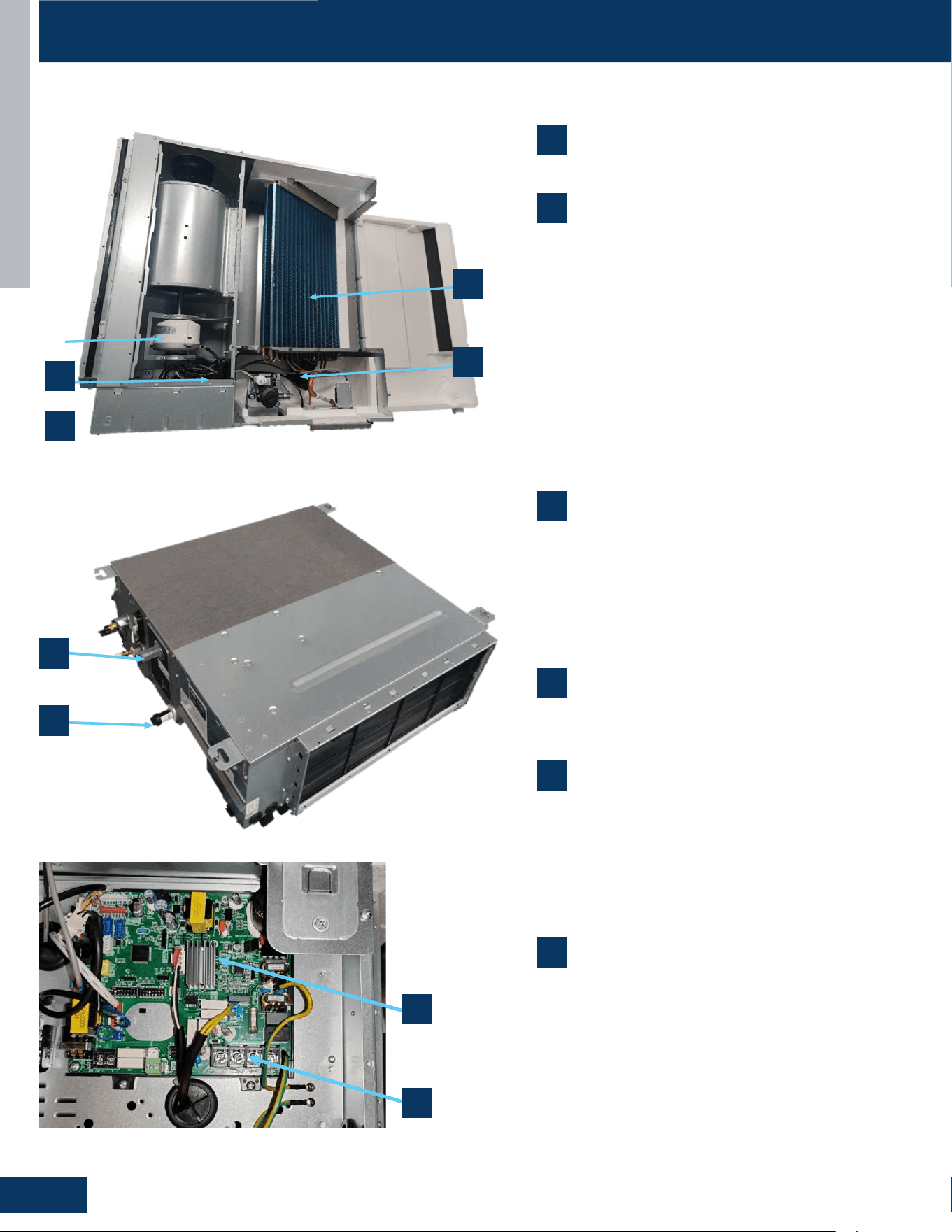
MID-STATIC DUCTED
F2
ENGLISH
COMPONENTS
US09MB2BEA / US12MB2BEA / US18MB2BEA
7
8
2
1
5
6
7
8
7
8
2
1
5
6
2
5
1
6
1. Evaporator Coil
2. Blower Assembly
The indoor unit features a DC variable speed blower motor that will change speed to
match the capacity demand from the outdoor unit. The motor powers blower assembly.
The blower assembly consists of 2 plastic blowers. A set screw holds each blower wheel
to the blower motor.
The indoor blower motor is connected to the indoor unit control board. The wiring from
the motor to indoor board consists of 3 wires connected to pins that deliver line v
oltage.
During normal operation, the indoor control board will energize the indoor blower
motor and request proper speed.
3
. Terminal Block
Power to operate the indoor unit comes from the electrical line voltage terminal block at
the outdoor unit. The wiring includes 4 wires, 1, 2, S and ground. Wires 1 and S complete
the data path. These wires should always be
14
gauge
AWG
stranded
cooper,
non-
shielded
type wire. Splices in wires 1 or S may cause communication errors.
3
4
4
3
1
Evaporator Coil
2
Blower Assembly
The indoor unit features a DC variable speed blower motor
that will change speed to match the capacity demand from
the outdoor unit. The motor powers blower assembly.
The blower assembly consists of 2 plastic blowers. A set
screw holds each blower wheel to the blower motor.
The indoor blower motor is connected to the indoor unit
control board. The wiring from the motor to indoor board
consists of 3 wires connected to pins that deliver line
voltage.
During normal operation, the indoor control board will
energize the indoor blower motor and request proper
speed.
3
Terminal Block
Power to operate the indoor unit comes from the electrical
line voltage terminal block at the outdoor unit. The wiring
includes 4 wires, 1, 2, S and ground. Wires 1 and S complete
the data path. These wires should always be 14 gauge AWG
stranded cooper, non-shielded type wire. Splices in wires 1
or S may cause communication errors.
5
Ambient Temperature Sensor
The Ambient Temperature Sensor senses room
temperature. This sensor provides room temperature
information to the ECU for calculation of inverter capacity
and temperature control. Both sensors are negative
temperature coecient type that reduce electrical
resistance as temperature rises.
6
Piping Temperature Sensor
The Piping Temperature Sensor senses indoor coil
temperature in the cooling mode and in the heating mode.
This sensor is used for Anti Freezing and Anti Cold Blow
cycles. The sensor also provides critical temperature
information to the ECU that may be used in frequency
adjustments.
4
Control Board
Located under the electrical control box cover.
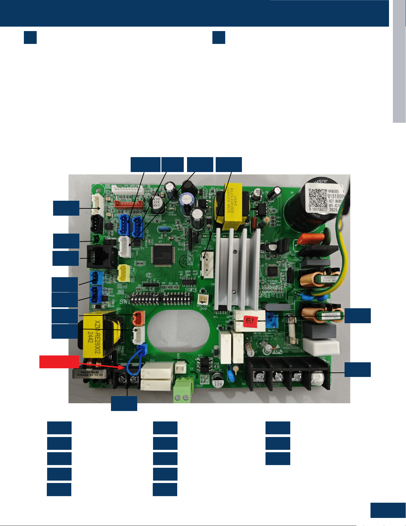
MID-STATIC DUCTED
F3
ENGLISH
COMPONENTS
US09MB2BEA / US12MB2BEA / US18MB2BEA
7
Condensate Pump
The Duct unit has a built-in condensate pump. The pump is
connected to the circuit board. The pump is energized whenever
the Float Switch indicates that water needs to be pumped from the
cassette. The oat switch connects onto the circuit board.
The oat switch and pump are located behind the removable
insulated cover next to the electrical control box. The pump is
hermetically sealed and requires no maintenance. The oat switch is
a normally closed switch, that opens as water rises. The oat switch
requires no maintenance.
8
Gravity Drain Ports
The indoor units have the option for either gravity drain systems or
the use of an internal condensate pump with oat switch. If high lift
is required, the water from the duct unit should be pumped to a eld
condensate pump that is capable of high lift.
Note: If the Internal condensate pump is not used (only gravity drain),
the condensate pump must be disconnected from the PCB (CN4).
Power Supply
OTA
Refrigerant Sensor
Drain Pump
Fan Motor
Wired Controller
Remote Communication
Up-and-Down Swing
Float Switch
WiFi
RJ45 Communication
Left and Right Swing
Sensor
PCB Overview
0151800986
US09MB2BEA US12MB2BEA US18MB2BEA US24MB2BEA US30MB2BEA US36MB2BEA US42MB2BEA US48MB2BEA
CN1
CN2
CN3
CN4
CN6
CN7
CN9
CN41
CN4
CN1
CN7
CN13
CN3
CN9
CN17
CN2
CN15
CN11-1
CN6
CN11
CN35
CN11
CN11-1
CN13
CN15
CN17
CN35
CN41
CN11-1 CN11 CN35
CN15
CN4
CN1
CN2
CN7
CN17
CN9
CN3
CN13
CN41
CN6
CN1 CN7 CN17
CN2 CN9 CN35
CN3
CN11-1
CN41
CN4 CN13
CN6 CN15
0151800986
JUMPER
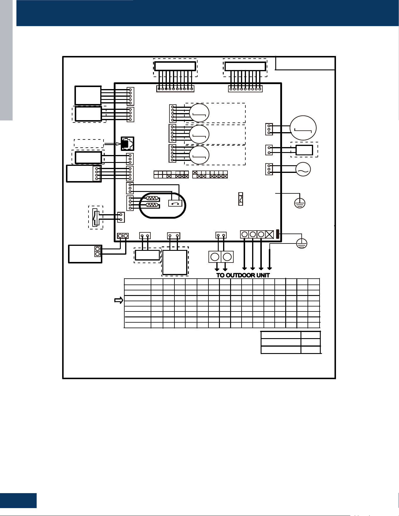
MID-STATIC DUCTED
F4
ENGLISH
WIRING DIAGRAM
US09MB2BEA / US12MB2BEA / US18MB2BEA
Factory default setting
of the DIP switches
SW1-1 SW1-2 SW1-3 SW1-4 SW1-6 SW1-7 SW1-8 SW3-1 SW3-2 SW3-3 SW3-4 SW3-5 SW3-6 SW3-7 SW3-8
US09MB2BEA
MODEL
OFF OFF OFF OFF OFF OFF OFF ON OFF OFF OFF OFF OFF OFF
ON
0150577393
OFF OFF OFF OFF OFF OFF OFF OFF OFF OFF OFF OFF
ON
OFF OFF OFF OFF OFF OFF OFF OFF OFF OFF
ON
OFF
ON ON
OFF OFF OFF OFF OFF OFF OFF OFF OFF OFF
ON
ON
US12MB2BEA
US18MB2BEA
US24MB2BEA
US30MB2BEA
ON
OFF
OFF
OFF OFF OFF F OFF
ON
OF
OFF
OFF OFF OFF
OFF
OFF
ON
OFF
1ESUF
CAV052/A3.6T
CN1
1(N) 2(L) 3(S)
AC PUMP
MOTOR
CN7
YL
YL
4NC
WIRED
CONTROLLER
ULB
Y/G
91NC
Y X
X Y
1 2 3
CN20
61NC
ROOM CARD
ULB
HW
14NC
Tp
Tr
31NC
FLOAT SWITCH
TO RJ45 device
3NC9NC
DR
Air conditioning
refrigerant detector
ULB
Central Controller
51NC
41NC
71NC
WIFI MODULE
Humidity Sensor
CN5
WH
FRELAY FOR
FRESH AIR
MOTOR(dry
Contact,rating
-230VAC,3A)/
E.A.0
M
UVC
93NC
HW
6NC
HW
M
DC FAN
ON SW1 ON
SW3
M
M
M
11NC1-11NC53NC
HW
ULB
ULB
KLB
Swing Motor2
Swing Motor3
Swing Motor1
LED DISPLAY
Display PCB
GRN
KLBHW
ULB
CN21
WH
CN31
RD
FRELAY FOR
Electric Heater
H1 H2
CN2
GRN
NOTE:
1.Dashed
parts are opt
ional.
2.Please refer to service manual to get details of the DIP switches definition .
3.Do not change the DIP switches setting without technical support.
4.Get details from trouble shooting list about LED indication.
5.Abbreviation
:
RD -red, W-withe,BLK-black,BLU-blue,GRN-green,YL-yellow,Y/G-yellow/green,E.A.O:
external alarm output,Tr
:
indoor unit ambient(room) temperature sensor,Tp
:
indoor unit pipe(coil)
temperatur
e
sensor.
6.The port CN10&CJ1&CJ2&CN22&P5 are dry contact output port for
particular use,do not connect other device without technical person support.
US36MB2BEA
US42MB2BEA
US48MB2BEA
OFF OFF OFF OFF OFF OFF OFF OFF OFF OFF OFF
OFF ON OFF OFF OFF OFF OFF OFF OFF OFF OFF OFFON
OFF OFF OFF OFF OFF OFF OFF OFF OFFON
ON
OFF
ON ON
ON
ON ON ON
Y/G
CON1
Wired
controller
display
07 flashing
on the upper
right corner
Outdoor error
code +20 cor-
respond HEX
code
Note:
1.To get much more details about the out door unit failure,please refer tothe outdoor unit trouble
shooting list.
2.SW1-5OFF Start the refrigerant sensor function,SW1-5ON Disable the refrigerant sensor function
Panel
display
bA
The refrigerant det-
ector is not installed
bA
No refrigerant detector is installed
AA
AA
Refrigerant leakage
Fault “AA” cannot be cleared. Only the
leakage concentration decreases and
the fault is turned to “Ab”.See the te-
chnical manual for elimination
Ac
Ac
The communication
of the refrigerant se-
nsor is faulty
When the air conditioner is running, t-
he cable harness of the refrigerant se-
nsor falls off.
Ad
Ad
The refrigerant sens-
or self-check is faulty
The refrigerant sensor is faulty.
AE
AE
Refrigerant sensor
life threshold
Refrigerant sensor life threshold rem-
inder
AF
AF
The refrigerant sens-
or expires
Refrigerant sensor life threshold, ne-
ed to be replaced
E1
E2
E4
F1-F45
01
02
04
07
0C
E7
E8
E12
E13
E14
0D
0E
Contents of Malfun-
ction
Malfunction of indoor
unit ambient tempera-
ture sensor
Malfunction of indoor-
unit piping temperatur-
e sensor
EEPROM wrong ofin-
door PCB
Abnormal communic-
ation between indoor
and outdoor units
Abnormal communic-
ation between wiredc-
ontroller and indoor
unit
Malfunction of drain-
system
Zero cross sigal wr-
ong
Indoor unit DC fanm-
otor abnormal
Outdoor unit error
Sensor disconected,or broken,or at
wrong position,orshort circuitsor.
Sensor disconected,or braken,or at
wrong position,orshort circuit.
EEPROM chip disconectedor broken
or wrong programmed,or PCB broken.
Wrong connection,or thewires be dis-
conected or wrong adress setting of
indoorunit or faulty power supplyor fa-
ulty PCB
Wrong connection or wiredcontroller
broken,or PCB faulty.
Pump motor disconnectedor at wrong
position,or thefloat switch,disconnec-
ted,or at wrong position, or theshort
circuit bridge disconneted
Zero cross sigal detected wrong.
DC Fan motor disconnectedor DC
Fan broken or circuitbroken
See correspond Outdoorunit error tro-
uble shooting.Remark: F1 means ou-
tdoor error code 1, F2 meansoutdoor
error code 2, andso on.
Possible reasons
Indoor unit trouble shooting
LED9 flash times
Tens
place
Ones
place
0
1
0
0
0
0
0
0
0
2
4
7
8
12
13
14
M(≥2)
N(≥0)
18
6
17
0
17
2
17
3
17
4
17
5
RD
BRN
SW1-5
Refrigerant Sensors
have
no
OFF
ON
ON
ON
ON
ON
ON
ON
ON

MID-STATIC DUCTED
F5
ENGLISH
DIP SWITCH & JUMPER SETTINGS
SW1-1 SW1-2 SW1-3 SW1-4 SW1-5 SW1-6 SW1-7 SW1-8 Description
OFF OFF OFF - - - - - 09K
ON OFF OFF - - - - - 12K
OFF ON OFF - - - - - 18K
- - - OFF - - - - Room Card Valid
- - - ON - - - - Room Card Invalid
- - - - OFF - - - Refrigerant Detector Functional
- - - - ON - - - The Refrigerant Detector Invalid
- - - - - OFF - - Fresh Air
- - - - - ON - - Fault Alarm
- - - - - - OFF - None - Filter Alarm Reminder + Refrigeration Fan Stops
- - - - - - ON - Filter Alarm Reminder + Refrigeration Fan Does Not Stop
- - - - - - - OFF Us Models
- - - - - - - ON Non-Us Models
DIP SW1
SW3-1 SW3-2 SW3-3 SW3-4 SW3-5 SW3-6 SW3-7 SW3-8 Description
OFF - - - - - - - Special Fresh Air Selection For Duct Unit: Valid
ON - - - - - - - Special Fresh Air Selection For Duct Unit: Invalid
- OFF - - - - - -
Cassette Single Swing Wind - Synchronized Swing Of
Swing Blades
- ON - - - - - -
Cassette Unit Four Swing Wind - Four Swing Blades
Swing At Dierent Angles, Misaligned Swing
- - OFF - - - - - Electrical Heating: Invalid
- - ON - - - - - Electrical Heating: Valid
- - - OFF - - - -
Model: Ultra-Slim Ducted Unit With 4-Level Static
Pressure
- - - ON - - - -
Model: Medium Static Pressure Duct With 10-Level
Static Pressure Adjustment
- - - - OFF OFF OFF OFF 0# (Wired Control Main) (Default)
- - - - OFF OFF OFF ON 1# (Line-Controlled Sub Machine)
- - - - OFF OFF ON OFF 2# (Line-Controlled Sub Machine)
- - - - OFF OFF ON ON 3# (Line-Controlled Sub Machine)
- - - - - - - - --
- - - -
ON ON ON ON 15# (Line-Controlled Sub Machine)
DIP SW3
RJ1 RJ2 RJ3 SW3-2 SW3-3 Description
OFF OFF OFF OFF OFF Crane
OFF OFF OFF OFF ON Cassette With 1 Oscillating Wind
OFF OFF OFF ON OFF Cassette With Four-Way Oscillating Wind
OFF OFF OFF ON ON Cassette With Light Panel
OFF OFF ON OFF OFF Console
OFF ON OFF OFF OFF Small Duct
OFF ON OFF OFF ON High-Capacity Duct
- - - - - Reserve
Jumper Settings - Model Identication
SW3_1 The fan selection function in cooling mode is only applicable to duct and slim duct.
SW3_4 Only applicable to slim duct
Suitable for convertible, 2HP cassette (matched with single swing wind), 2HP cassette (matched with four swing wind), 3HP cassette (equipped
with display board). For example, if the convertible has 0 0 0 0, the resistance should be welded RJ1/RJ2/RJ3. Simultaneously dial the second
digit of code BM3 to OFF and the third digit to OFF. The same setup method is used for other models.
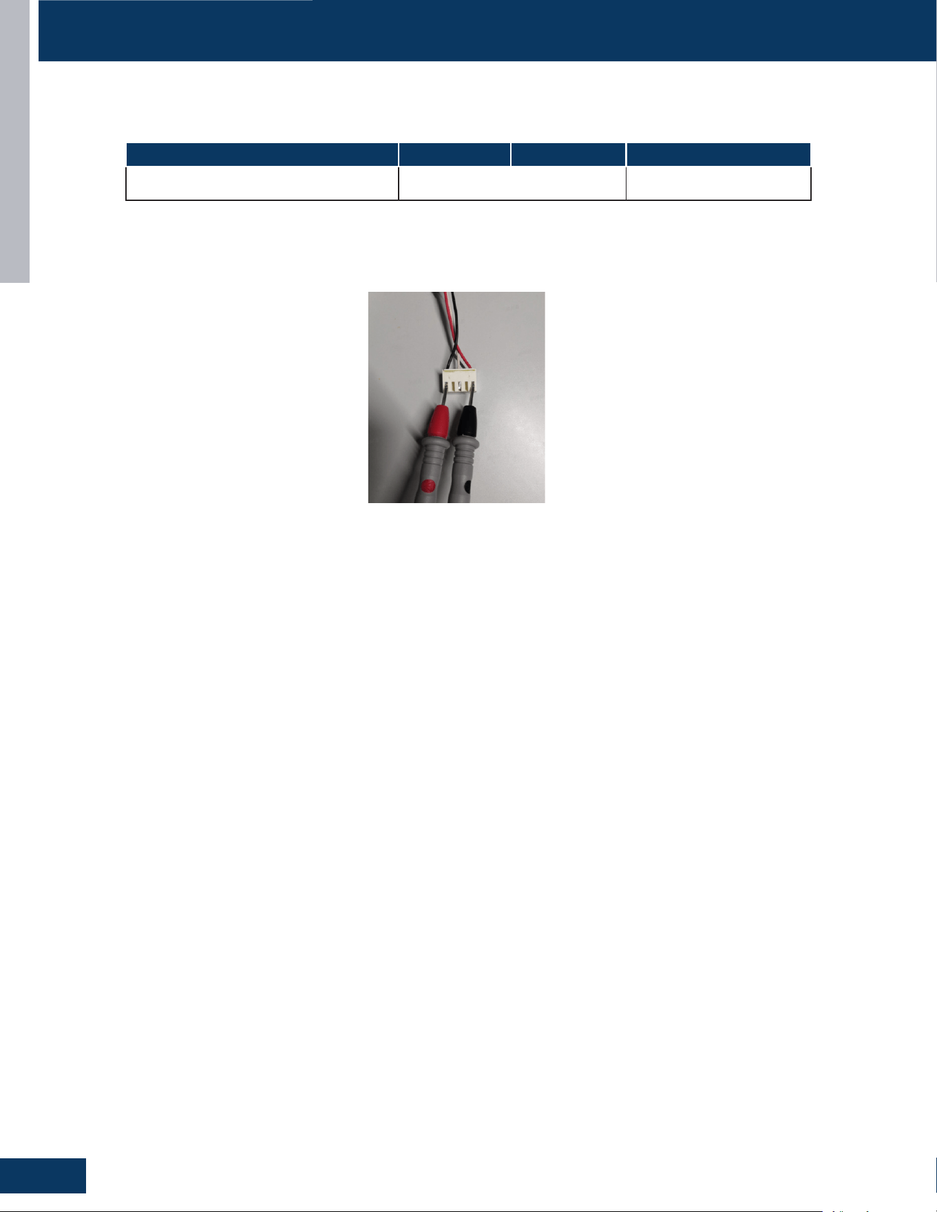
MID-STATIC DUCTED
F6
ENGLISH
SERVICE PROCEDURES
Resistance Values
Measure the Resistance :
Use a multimeter to measure the resistance between any two phases (U, V, W) of the motor (as shown in the following diagram).
Model US09CB2BEA US12CB2BEA US18CB2BEA
Fan Motor Resistance Value 0150401249C, 20.6±7% 0150402221C, 12.5±7%
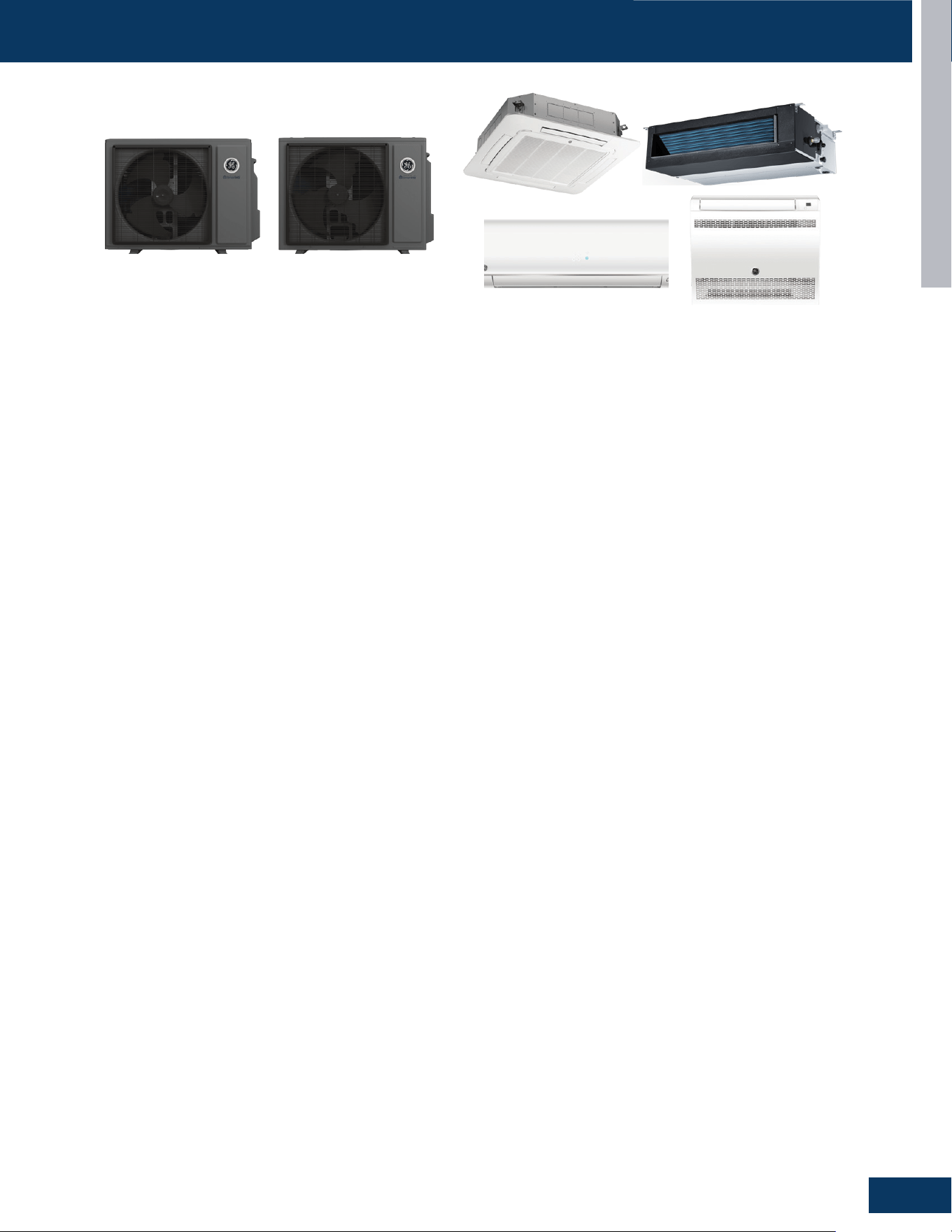
TROUBLESHOOTING & REFERENCES
G1
ENGLISH
TROUBLESHOOTING & REFERENCES
TABLE OF CONTENTS
ERROR CODES ........................................................................................................................................................................G2
TROUBLESHOOTING FLOWCHARTS
......................................................................................................................................G3
E1/LED1: No Flash ................................................................................................................................................................. G4
E2/LED1: No Flash ................................................................................................................................................................. G4
F21/LED1: 10 Flash ............................................................................................................................................................... G4
F25/LED1: 13 Flash ............................................................................................................................................................... G4
F6/LED1: 12 Flash .................................................................................................................................................................. G4
E4 ......................................................................................................................................................................................... G5
F12/ LED1: 1 Flash ................................................................................................................................................................. G5
F20/LED1: 5 Flash .................................................................................................................................................................. G5
E14 ......................................................................................................................................................................................... G6
F1/LED1: 2Flash .................................................................................................................................................................... G7
F8/LED1: 9Flash .................................................................................................................................................................... G8
F19/LED1: 6 Flash .................................................................................................................................................................. G9
F22/LED1: 3 Flash ................................................................................................................................................................ G10
F2/LED1: 25 Flash ................................................................................................................................................................ G10
F4/LED1: 8 Flash .................................................................................................................................................................. G11
E7/LED1: 15 Flash ............................................................................................................................................................... G12
F11/LED1: 18 or 19 Flash .................................................................................................................................................... G13
LED1: 21 Flash ..................................................................................................................................................................... G13
LED1: 28 Flash ..................................................................................................................................................................... G14
E22/LED1: 21 Flash ............................................................................................................................................................. G14
F27/LED1: 21 Flash ............................................................................................................................................................. G14
F2/LED1: 24 Flash ................................................................................................................................................................ G15
bA ....................................................................................................................................................................................... G16
AA and Ab ............................................................................................................................................................................. G17
Ac ....................................................................................................................................................................................... G18
Ad ....................................................................................................................................................................................... G19
AE ....................................................................................................................................................................................... G20
AF ....................................................................................................................................................................................... G21
SENSOR RESISTANCE TABLES ..............................................................................................................................................G22
SENSOR RESISTANCE VALUES
.............................................................................................................................................G28
TROUBLESHOOTING & REFERENCES
G2
ENGLISH
ERROR CODES
OUTDOOR UNITS
FAULT DESCRIPTION
INDOOR UNIT
LED DISPLAY DIGITAL DISPLAY
/ INDOOR AMBIENT TEMPERATURE SENSOR FAILURE E1
/ INDOOR COIL TEMPERATURE SENSOR FAILURE E2
/ INDOOR PCB EEPROM FAILURE E4
15 COMMUNICATION FAILURE BETWEEN THE INDOOR & OUTDOOR UNIT E7
/ INDOOR FAN MOTOR MALFUNCTION E14
21 IDU ANTI-FROSTING PROTECTION (COOLING MODE ONLY) /
21 INDOOR UNIT OVERLOAD PROTECTION, HEATING MODE ONLY. /
28 LACK OF REFRIGERANT OR DISCHARGING /
1 OUTDOOR EEPROM FAILURE F12
2 IPM OVERCURRENT OR SHORT CIRCUIT F1
3 OUTDOOR ALTERNATING CURRENT, OVER CURRENT PROTECTION F22
5 MODULE OPERATED OVERLOAD (COMPRESSOR OVERLOAD PROTECTION) F20
6 MODULE LOW OR HIGH VOLTAGE F19
7 COMPRESSOR CURRENT SAMPLING CIRCUIT FAULT F27
8 OVERHEAT PROTECTION FOR DISCHARGE TEMPERATURE F4
9 MALFUNCTION OF THE DC FAN MOTOR F8
10 MALFUNCTION OF DEFROST TEMPERATURE SENSOR F21
12 AMBIENT TEMPERATURE SENSOR FAILURE F6
13 DISCHARGE TEMPERATURE SENSOR FAILURE F25
24 COMPRESSOR START FAILURE, OVER-CURRENT F2
25 PHASE CURRENT PROTECTION (IPM) F23
/ REFRIGERANT LEAK FAULT >10% LFL AA
/ REFRIGERANT LEAK FAULT <8% LFL Ab
/ LEAK SENSOR COMMUNICATION FAULT Ac
/ LEAKAGE SENSOR SELF-CHECK FAULT - SELF CHECK FAULT Ad
/ SENSOR REACHING END OF LIFE WARNING AE
/ SENSOR REACHING END OF LIFE AF
/ DIP SWITCH ENABLED, NO SENSOR DETECTED bA
1G09ED2BEA/GS09WP2BEA, 1G12ED2BEA/GS12WP2BEA, 1G18ED2BEA/GS18WP2BEA
PANEL
DISPLAY
WIRED
CONTROLLER
DISPLAY (YR-E17)
DESCRIPTION POSSIBLE CAUSES
E1 01
INDOOR UNIT AMBIENT TEMPERATURE
SENSOR MALFUNCTION
SENSOR DISCONNECTED,OR BROK EN,OR AT WRONG
POSITION,OR SHORT CIRCUIT
E2 02
INDOOR UNIT PIPING TEMPERATURE
SENSOR MALFUNCTION
SENSOR DISCONNECTED,OR B ,K EN,OR AT WRONG POSITION
OR SHORT CIRCUIT
E4 04 INDOOR PCB EEPROM WRONG
EEPROM CHIP DISCONNECTED OR BROKEN OR WRONG
PROGRAM- MED OR PCB BROKEN
E7 07
ABNORMAL COMMUNI CATION BETWEEN
INDOOR AND OUTDOOR UNITS
WRONG CONNECTION, WIRES DISCONNECTED, WRONG
ADDRESS SETTING OF INDOOR UNIT, FAULTY POWER SUPPLY,
OR FAULTY PCB
EB
07 FLASHING ON
THE UPPER RIGHT
CORNER
ABNORMAL COMMUNICATION BETWEEN
WIRED CONTROLLER AND INDOOR UNIT
WRONG CONNECTION, WIRED CONTROLLER BROKEN, OR
PCB FAULTY.
E12 0C DRAIN SYSTEM MALFUNCTION
PUMP MOTOR DISCONNECTED OR AT WRONG
POSITION,FLOAT SWITCH DISCONNECTED, WRONG
POSITION, OR SHORT CIRCUIT BRIDGE DISCONNECTED
E13 0D ZERO CROSS SIGNAL WRONG ZERO CROSS SIGNAL DETECTED WRONG.
E14 0E INDOOR UNIT DC FAN MOTOR ABNORMAL
DC FAN MOTOR DISCONNECTED, FAN BROKEN, OR CIRCUIT
BROKEN
F1-- F45
OUTDOOR
ERROR CODE+20
CORRESPOND
HEX CODE
OUTDOOR UNIT ERROR
SEE CORRESPOND OUTDOOR UNIT ERROR TROUBLE
SHOOTING. REMARK: F1 MEANS OUTDOOR ERROR CODE 1,
F2 MEANS OUTDOOR ERROR CODE 2, AND SO ON.
US09FB2BEA / US12FB2BEA / US18FB2BEA
TROUBLESHOOTING & REFERENCES
G3
ENGLISH
ERROR CODES
US09CB2BEA / US12CB2BEA / US18CB2BEA / US24LB2BEA / US30LB2BEA / US36LB2BEA
US09MB2BEA / US12MB2BEA / US18MB2BEA / US24MB2BEA / US30MB2BEA / US36MB2BEA
LED2 FLASH TIMES
PANEL
DISPLAY
WIRED
CONTROLLER
DISPLAY
DESCRIPTION POSSIBLE CAUSES
TENS
PLACE
ONES
PLACE
0 1 E1 1
INDOOR UNIT AMBIENT TEMPERATURE
SENSOR MALFUNCTION
SENSOR DISCONNECTED, BROKEN, AT
WRONG POSITION, OR SHORT CIRCUIT.
0 2 E2 2
INDOOR UNIT PIPING TEMPERATURE
SENSOR MALFUNCTION
SENSOR DISCONNECTED, BROKEN, AT
WRONG POSITION, OR SHORT CIRCUIT.
0 4 E4 4 INDOOR PCB EEPROM WRONG
EEPROM CHIP DISCONNECTED, BROKEN,
WRONG PROGRAMMED, OR PCB BROKEN.
0 7 E7 7
ABNORMAL COMMUNICATION BETWEEN
INDOOR AND OUTDOOR UNITS
WRONG CONNECTION, WIRES
DISCONNECTED, WRONG ADDRESS
SETTING OF INDOOR UNIT, FAULTY POWER
SUPPLY, OR FAULTY PCB
0 8 E8
07 FLASHING
ON THE
UPPER RIGHT
CORNER
ABNORMAL COMMUNICATION BETWEEN
WIRED CONTROLLER AND INDOOR UNIT
WRONG CONNECTION, WIRED
CONTROLLER BROKEN, OR PCB FAULTY.
0 12 E12 0C DRAIN SYSTEM MALFUNCTION
PUMP MOTOR DISCONNECTED OR
AT WRONG POSITION,FLOAT SWITCH
DISCONNECTED, WRONG POSITION, OR
SHORT CIRCUIT BRIDGE DISCONNECTED
0 13 E13 0D ZERO CROSS SIGNAL WRONG ZERO CROSS SIGNAL DETECTED WRONG.
0 14 E14 0E INDOOR UNIT DC FAN MOTOR ABNORMAL
DC FAN MOTOR DISCONNECTED, FAN
BROKEN, OR CIRCUIT BROKEN
M(≥2) N(≥0) F1-F45
OUTDOOR
ERROR
CODE +20
CORRESPOND
HEX CODE
OUTDOOR UNIT ERROR
SEE CORRESPOND OUTDOOR UNIT ERROR
TROUBLESHOOTING. REMARK: F1 MEANS
OUTDOOR ERROR CODE 1, F2 MEANS
OUTDOOR ERROR CODE 2, AND SO ON.
18 6 bA BA
THE REFRIGERANT DETECTOR IS NOT
INSTALLED
NO REFRIGERANT DETECTOR IS INSTALLED
17 0 AA AA REFRIGERANT LEAKAGE
FAULT “AA” CANNOT BE CLEARED.
ONLY THE LEAKAGE CONCENTRATION
DECREASES AND THE FAULT IS TURNED
TO “AB”. SEE THE TECHNICAL MANUAL FOR
ELIMINATION
17 2 Ac AC
THE COMMUNICATION OF THE
REFRIGERANT SENSOR IS FAULTY
WHEN THE AIR CONDITIONER IS
RUNNING, THE CABLE HARNESS OF THE
REFRIGERANT SENSOR FALLS OFF.
17 3 Ad AD
THE REFRIGERANT SENSOR SELF CHECK IS
FA U LT Y
THE REFRIGERANT SENSOR IS FAULTY.
17 4 AE AE REFRIGERANT SENSOR LIFE THRESHOLD
REFRIGERANT SENSOR LIFE THRESHOLD
REMINDER
17 5 AF
AF THE REFRIGERANT SENSOR EXPIRES
REFRIGERANT SENSOR LIFE THRESHOLD,
NEED TO BE REPLACED
Note:
1. For more details about the outdoor unit failure, please refer to the outdoor unit troubleshooting list.
2. SW1-5 OFF: Start the refrigerant sensor function. SW1-5 ON: Disable the refrigerant sensor function.
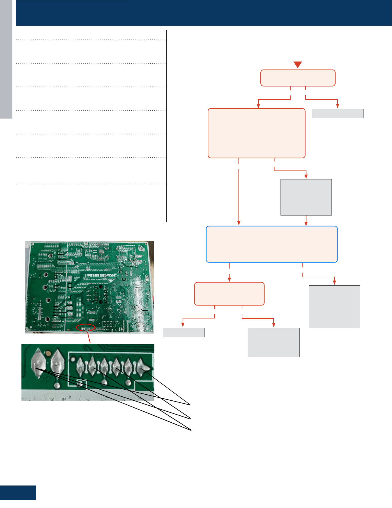
TROUBLESHOOTING & REFERENCES
G4
ENGLISH
Yes
Yes
Yes
Yes
No
No
No
Re-seat connector
Replace sensor. Go
to next step to test
the board as well
before replacing
sensor.
No
Replace main board.
Replace sensor as
well if resistance
was incorrect in the
previous step.
Re-seat and
re-check sensor
resistance with a
different meter.
Replace sensor
Start
Is connector plugged in and
seated securely?
Disconnect power and unplug senor
connector from the board.
Check resistance across the set of
wires for the faulting sensor. Does
the resistance correspond to the
temperature located in the respective
chart?
Reconnect sensor to the board and re-apply power.
Check voltage between the two corresponding solder
joints or through the top of the Molex connector
depending on sensor confıguration.
Is the voltage ~5VDC?
Is the temperature at the
sensor out of operating
range (+/- 3%)?
5V Discharge Temperature Sensor
5V Defrost Temperature Sensor
5V Ambient Temperature Sensor
TROUBLESHOOTING FLOWCHARTS
Error Codes (Indoor/Outdoor)
E1/LED1: No Flash
Room Temperature Sensor Failure
E2/LED1: No Flash
Indoor Coil Temperature Sensor Failure
F21/LED1: 10 Flash
Defrost Temperature Sensor Failure
F25/LED1: 13 Flash
Discharge Temperature Sensor Failure
F6/LED1: 12 Flash
Ambient Temperature Sensor Failure
Detection Conditions:
Thermistor input is more than 4.92V or less than 0.08V
during compressor operation.
Possible Causes:
• Faulty connector connection
• Faulty thermistor
• Faulty PCB
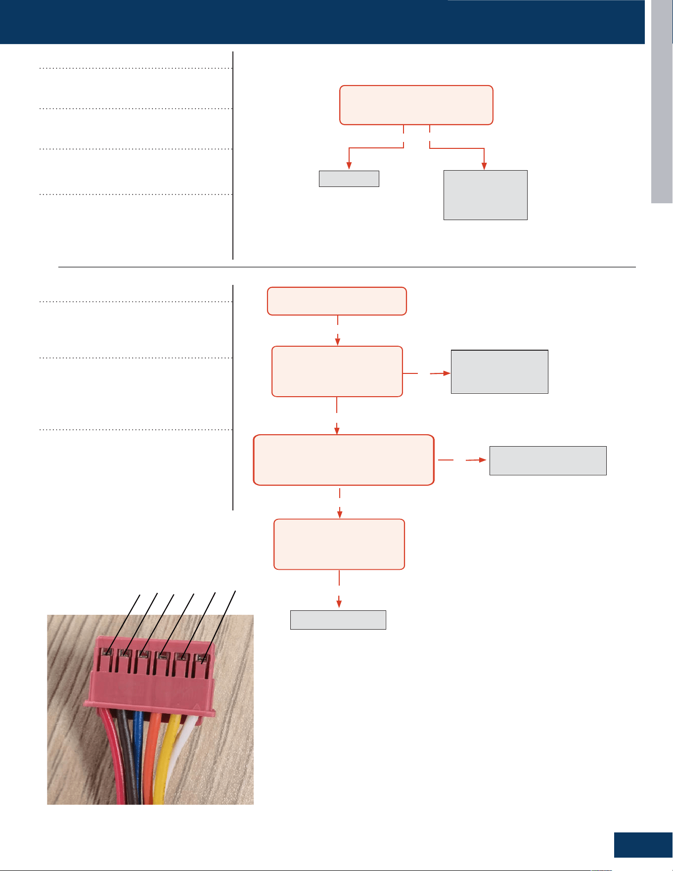
TROUBLESHOOTING & REFERENCES
G5
TROUBLESHOOTING FLOWCHARTS
ENGLISH
Yes
No
The 10-minute
reboot has
corrected the issue
Replace PCB
After 10 minutes with the power off,
the 1-flash reappears with power
turned back on?
31-5000931 Rev. 0
No
Yes
After the unit has been cut off the
power for more than 20mins
Measure the resistance between 6 and 4,
6 and 2,5 and 3,5 and 1, and the resistance
between them is roughly the same,
all less than 100 ohms
Check whether the wiring
terminal CN16 of electronic
expansion valve is
connected well.
Connect the wires well
according to the wiring
diagram.
Yes
Replace the coil of electronic
expansion valve.
Yes
Check whether the refrigerant is
leaking; if yes, please charge the
refrigerant according to the
technical specification.
No
No
Replace main PCB
1
6
5
4
3
2
Error Codes (Indoor/Outdoor)
E4
Indoor EEPROM Error
F12/ LED1: 1 Flash
Outdoor EEPROM Error
Detection Conditions:
EEPROM data error or the EEPROM is
damaged
Possible Causes:
• Faulty EEPROM data
• Faulty EEPROM
• Faulty PCB
Error Codes (Indoor/Outdoor)
F20/LED1: 5 Flash
Module operated overload
(compressor overload protection)
Detection Conditions:
Measure the resistance between 6 and 4,6
and 2,5 and 3,5 and 1, and the resistance,
between them is roughly the same, all less
than 100 ohms.
Possible Causes:
• Electronic Expansion Value is bad
• Electronic Expansion Value terminal is
bad
• Lack of refrigerant
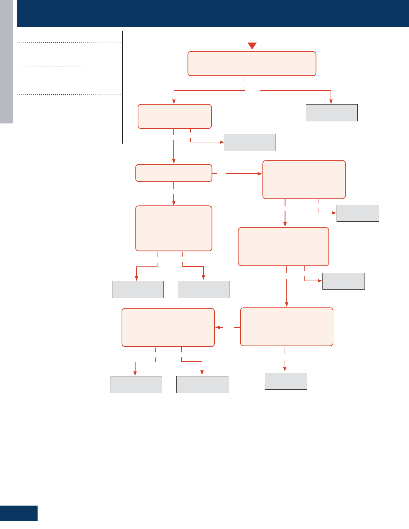
TROUBLESHOOTING & REFERENCES
G6
ENGLISH
Yes
Yes
Yes
Yes
No
Yes No
No
Fix incoming power
supply
Replace the fan
motor
Replace the main
board.
Replace the fan
motor
Replace the
main board.
Replace the
main board.
Replace the
main board.
Start
With the power off, turn the
fan by hand. Does it move /
rotate smoothly?
Check the incoming voltage. Is it 208/230VAC (+/-
10%) between L1/L2? 104/115VAC (+/- 10%) from
L1 to GROUND and L2 to GROUND?
Re-apply power. Does the fan
come on and spin?
Measure DC voltage at fan
motor plug CN9 between
the Pin 7 (BLUE) and Pin 4
(BLACK) wire while spinning
the fan motor.
Does it generate 2~9VDC?
Measure DC voltage at fan
motor plug CN9 between Pin 1
(RED) and Pin 4 (BLACK).
Does it measure 300~380VDC
(+/-10%)?
Measure DC voltage at fan motor
plug CN9 between Pin 5 (WHITE)
and Pin 4 (BLACK).
Does it measure between
13.5-16.5VDC?
No
No
No
Yes
Replace the main
board.
Replace the fan
motor
Measure DC voltage at fan motor
plug CN9 between Pin 6 (YELLOW)
and Pin 4 (BLACK).
Does it measure between 2-6VDC?
Measure DC voltage at fan motor
plug CN9 between the Pin 7 (BLUE)
and Pin 4 (BLACK) wire while
spinning the fan motor.
Does it generate 2~9VDC?
No
Yes
No
Yes
TROUBLESHOOTING FLOWCHARTS
Error Code (Indoor)
E14
Indoor Fan Motor Failure
Detection Conditions:
No rotation feedback signal detected
for 2 minutes
Possible Causes:
• Faulty fan motor
• Fan motor overheat protection
• Detection error due to faulty indoor
unit PCB
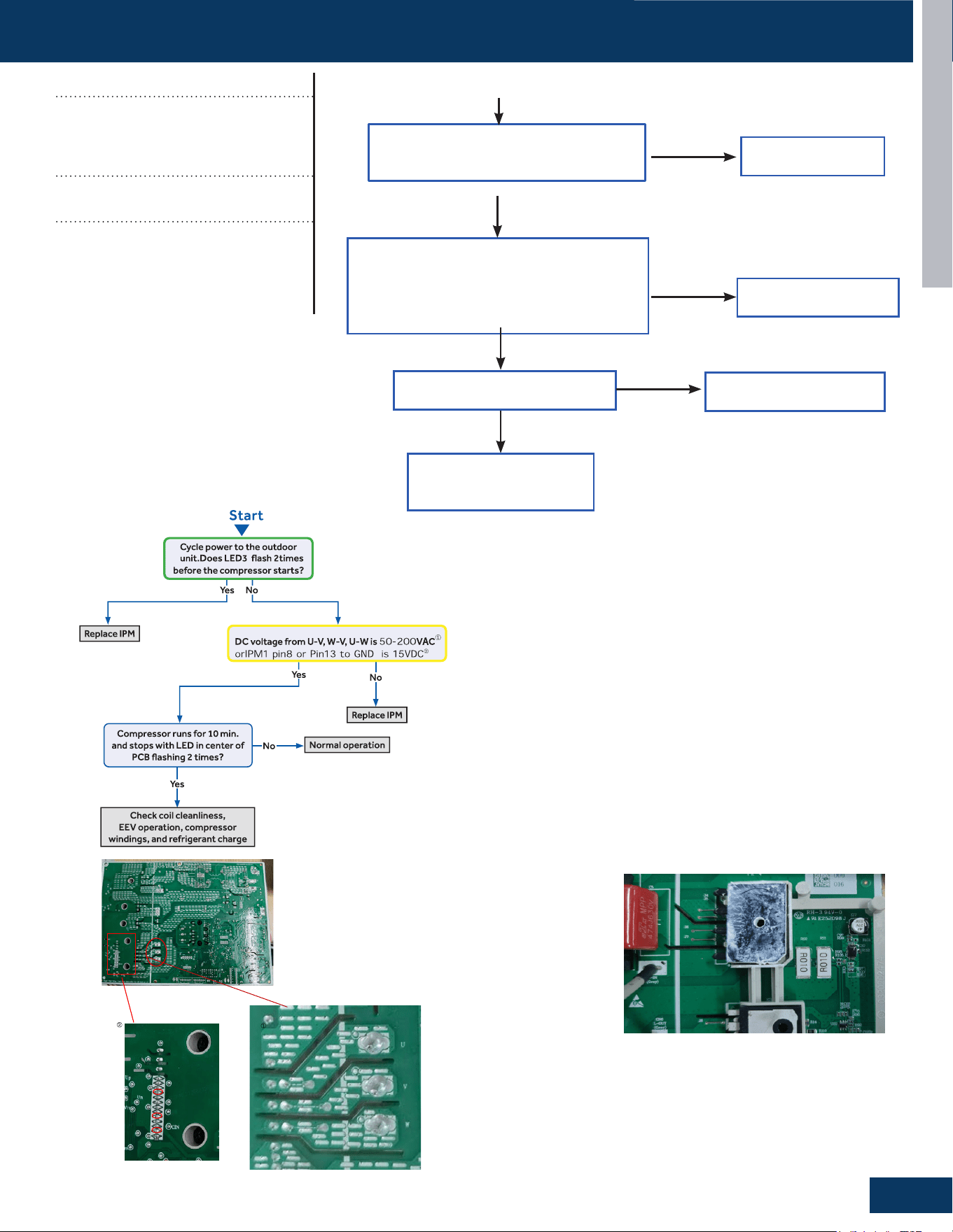
TROUBLESHOOTING & REFERENCES
G7
ENGLISH
TROUBLESHOOTING FLOWCHARTS
PIN8
PIN13
GND
IPM Detect Process Below:
Correct the wiring
Is electric box wiring correct,
and is compressor wiring rmly
connected?
Is compressor normal (compressor coil
resistor, insulation)?
0010744188 2.67±5%Ω
Is power module normal?
Replace compressor
Replace power module
Yes
Yes
Yes
No
No
No
Solve or correct any
failures according to
relative information
Start
ENGLISH
Trigger condition:
The abnormal resistance value of R010
was collected, resulting F1 fault occures.
TROUBLESHOOTING FLOWCHARTS
Error Codes (Indoor/Outdoor)
F1/LED1: 2 Flash
IPM Power Module Failure
(PM power module protection)
Detection Conditions:
Amp limit hot 3 times in 30 minutes
Possible Causes:
• IPM bad
• Loose compressor wire
• Bad compressor
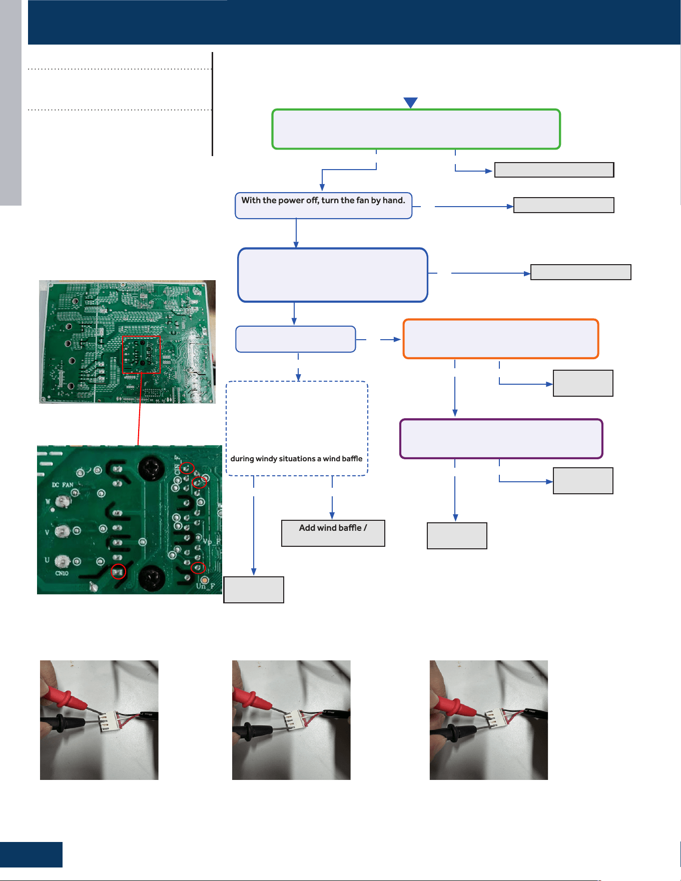
TROUBLESHOOTING & REFERENCES
G8
ENGLISH
No
Ye s
Ye s
Ye s
Ye s
No
Ye s
No
protection from wind.
Fix incoming power supply
Replace the fan motor
Replace the
fan motor.
Replace the
main board.
Start
Check the incoming voltage.
Is it 115VAC (+/- 10%) between L/N?
Does it move / rotate smoothly?
Re-apply power. Does the
fan come on and spin?
No
No
Replace the
main board.
Replace the
main board.
Measure DC voltage at fan motor IPM2 pin1
to GND,Does it measure 160~320VDC (+/-
10%)?
Measure DC voltage at fan motor IPM2
between Pin11 and pin8 ,Does it measure
between 13.5-16.5VDC?
Before going to the next step, is the
unit in an area susceptible to high
winds? High winds blowing into the
fan may cause added resistance
and subsequently lower fan speeds
enough to cause the unit to fault. If
this is the case the unit only faults
may need to be added.
Not Windy Windy
Measure the three wire harnesses of the
motor UVW, and check whether the
resistance values between any two wire
harnesses is 101±8%Ω
Replace the fan motor
No
Ye s
PIN1
GND
PIN8
PIN11
TROUBLESHOOTING FLOWCHARTS
Error Codes (Indoor/Outdoor)
F8/LED1: 9 Flash
Outdoor DC Fan Motor Fault
Detection Conditions:
Resistance values between any two wire
harness connections is 101 +8%Ω
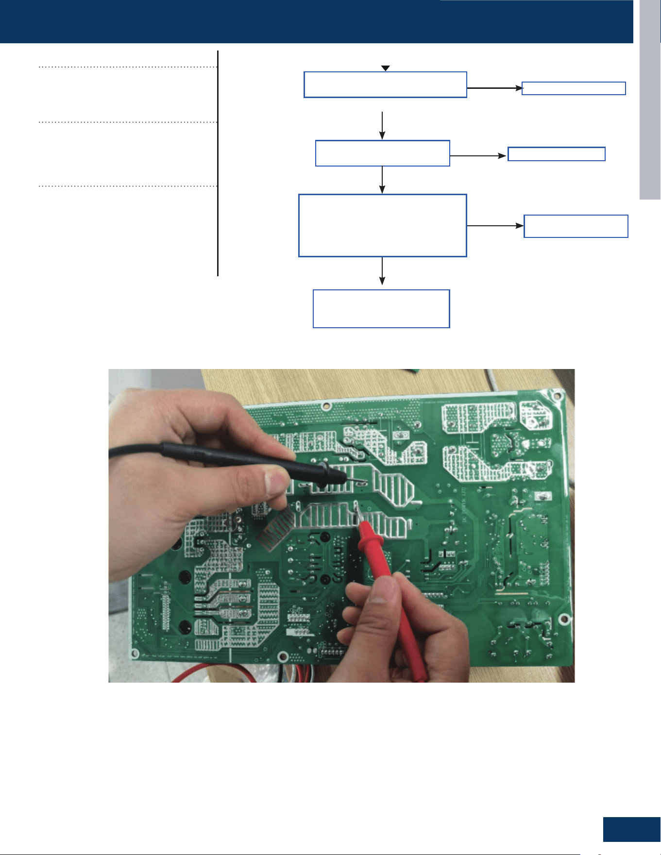
TROUBLESHOOTING & REFERENCES
G9
ENGLISH
Correct power supply
Correct the wiring
Replace power module
Correct power supply
Is power supply voltage
normal?
Is electric box wiring
correct?
Is power module voltage
between terminal P&N more
than 390V or less than 90V
during operation?
Replace power module
Yes
Yes
No
No
Check rectier, rector,
electrolytic capacitor on
inverter main circuit
No
Yes
Start
Replace power module
Correct power supply
TROUBLESHOOTING FLOWCHARTS
Error Codes (Indoor/Outdoor)
F19/LED1: 6 Flash
Power supply is over voltage or
under voltage
Detection Conditions:
• Abnormal voltage detection
• Terminal P&N more than 390V or less
than 90V during operation
• Possible Causes:
Supply voltage not as specied
• Faulty IPM module
• Faulty outdoor PCB
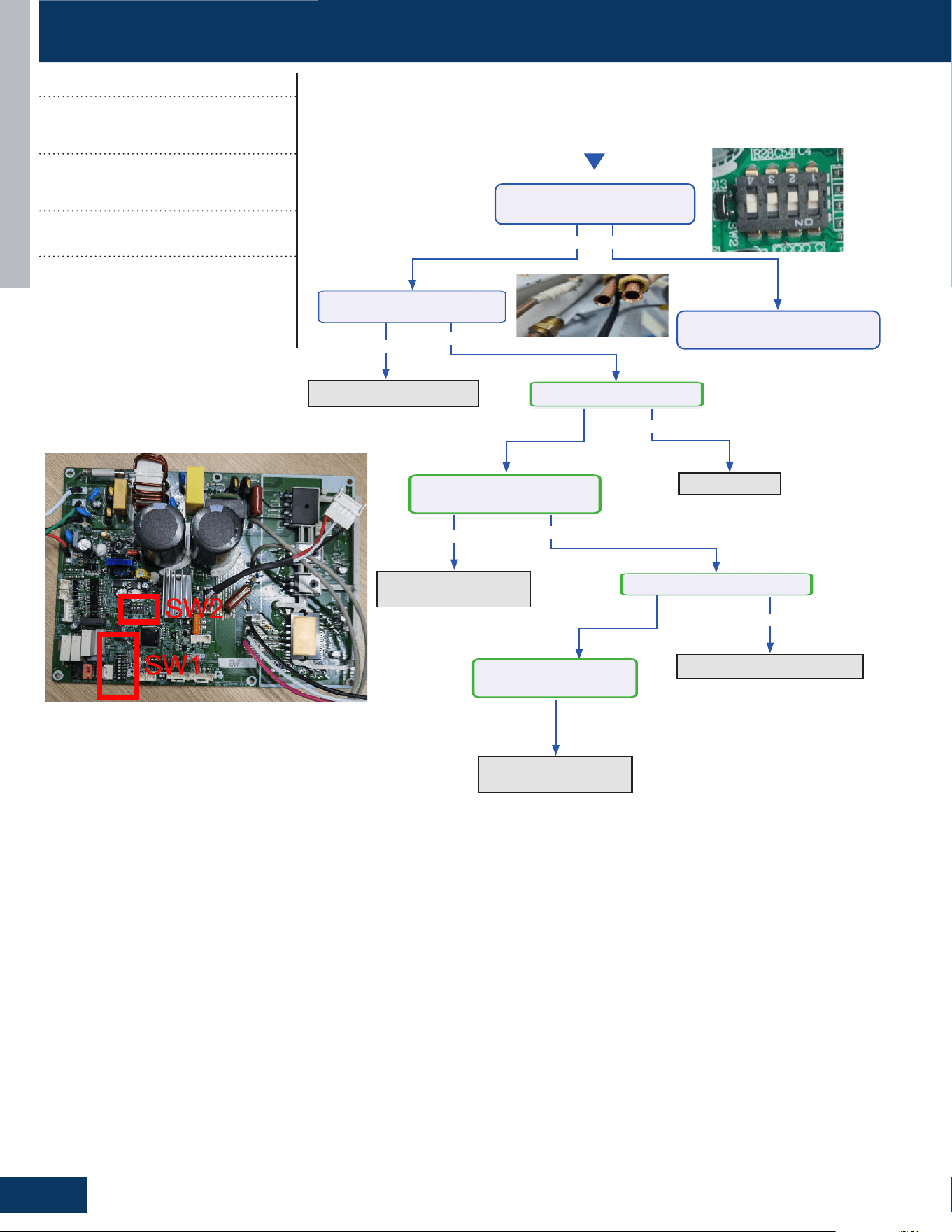
TROUBLESHOOTING & REFERENCES
G10
ENGLISH
Start
Ye s
Ye s
Ye s
Ye s No
No
No
Replace
connecting
pipe
Check for a fan motor
issue
or replace
Replace the EEV
Open louver
PCheck whether the DI I
switch SW-2 is correct?
Indoor louver closed?
The indoor fan rotates slowly
or abnormally
The outdoor EEV damaged
PAdj ust DI I switch
blockage of connecting
pipe
?
Ye sNo
No
The outdoor fan rotates
slowly or abnormally
Check for a fan motor
issue
or replace
TROUBLESHOOTING FLOWCHARTS
Error Codes (Indoor/Outdoor)
F22/LED1: 3 Flash
AC current overload
F23/LED1: 35 Flash
Phase current protection
Detection Conditions:
Current value is over 14.4A
Possible Causes:
• Incorrect compressor wiring
• The power module is bad
• The compressor is bad
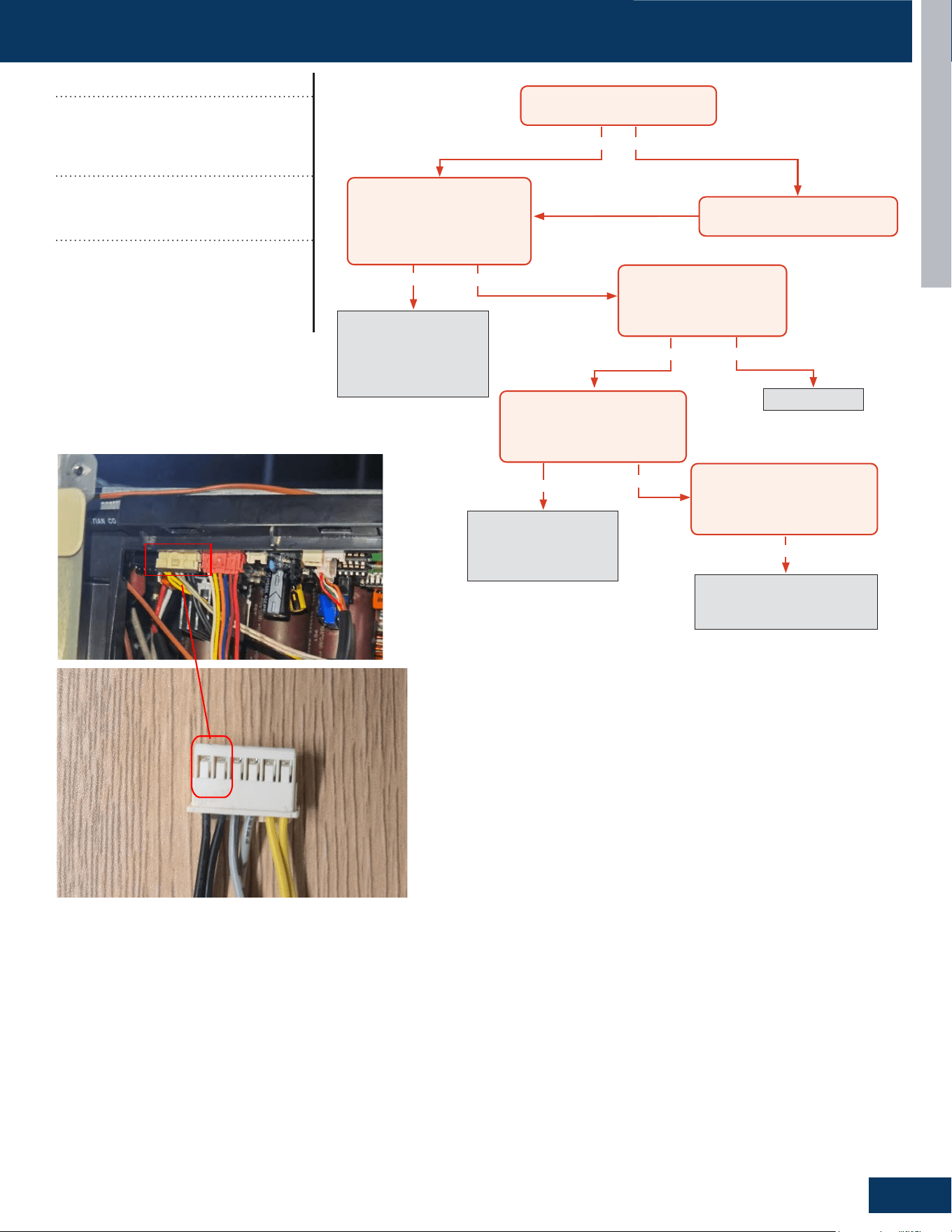
TROUBLESHOOTING & REFERENCES
G11
ENGLISH
Yes
Yes
Yes
Yes No
No
No
Yes
No
Recover refrigerant,
remove moisture and
air from system, charge
with fresh refrigerant to
nameplate amount
Check for a fan motor
issue, restricted line set or
EEV, or lack of refrigerant
Check for a plugged coil or
fılter, a high load, or incorrect
refrigerant charge
Replace sensor
The discharge line temperature is
below 230°F/110°C?
The discharge sensor
ohmreading matches
the resistance table in the
Service Manual?
With system on, the discharge
sensor climbs to 230°F within a
short time, and the compressor
stops?
With system on, the discharge
sensor climbs to 230°F after
several minutes, and the
compressor stops?
Turn power off for 20 min. to
allow the discharge line to cool
Refrigerant static test (system
off for 20 min.) indicates
head pressure converted to
temperature is higher than
ambient?
Mesure this two wire to check resistance
TROUBLESHOOTING FLOWCHARTS
Error Codes (Indoor/Outdoor)
F4/LED1: 8 Flash
Overheat Protection for
Discharge Temperature
Detection Conditions:
Compressor discharge temperature
above 110
O
C
Possible Causes:
• Faulty electronic expansion valve
• Faulty thermistor
• Faulty PCB
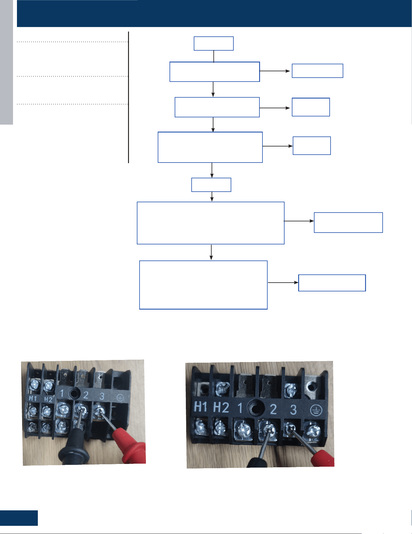
TROUBLESHOOTING & REFERENCES
G12
ENGLISH
Replace wire
Is the communication wire is
shorted?
Is the communication wire
CN23 is disconnected?
Reconnect
Reconnect
Yes
No
No
Yes
Is the wiring connection sequence
correct according to the wiring
diagram?
No
Measure the outdoor terminal block voltage
between communication 3 and 2, and measure the
indoor terminal block between communication 3
and 2 to check. Is the communication wire ok?
Yes
Replace the
communication wire
Power o
Power on
No
Yes
Using a multimeter, measure the terminal
corresponding to the N-line voltage of CN21
from the indoor unit with the communication
failure. Is the voltage normal?
No
PCB is bad, replace PCB
outdoor terminal
indoor terminal
TROUBLESHOOTING FLOWCHARTS
Error Codes (Indoor/Outdoor)
E7/LED1: 15 Flash
ID and OD Loss of
Communication
Detection Conditions:
Outdoor PCB communication failure
• Indoor PCB communication failure
Possible Causes:
• Communication wiring disconnected
• Faulty indoor PCB
• Faulty outdoor PCB
• Faulty Outdoor Fan (may cause com-
munication signal interference)
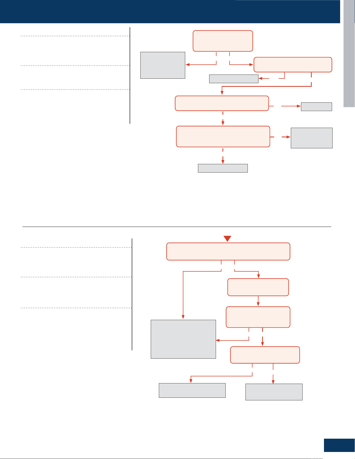
TROUBLESHOOTING & REFERENCES
G13
ENGLISH
No
No
Yes
Momentary loss of
building power or
acceptable power
quality
Replace compressor
Replace compressor
Replace IPM
Repair or replace
wiring or
connections
When power is off for 5
min. and turned back on,
the compressor runs?
A windings or grounding check
shows issues with compressor?
There is 50-200 VAC across the U, V, and
W solder points on the IPM?
The compressor wires are on the
correct terminals, free of breaks and the
connections at both end are secure?
Yes
Yes
Yes
No
No
No
No
Yes
Yes No
Start
Cycle power to the outdoor unit. Turn system on via
remote control. Does the error occur immediately?
Allow system to run until
error code is displayed
Troubleshoot the pipe
temperature sensor and
temperature monitoring
circuit of the indoor main
board. Replace components
found faulty.
Service the fan or clean
fılters as necessary.
Measure system charge level
and adjust as required.
Yes
Is the pipe at the location of
the pipe temperature sensor
under 149
O
F?
Is fan motor running properly
and fılters unobstructed?
TROUBLESHOOTING FLOWCHARTS
Error Codes (Indoor/Outdoor)
F11/LED1: 18 or 19 Flash
Loss of Compressor
Synchronization
Detection Conditions:
Compressor faulty, miswired or wiring
connection faulty
Possible Causes:
• Faulty wiring
• Faulty compressor
• Faulty PCB
Error Codes (Outdoor)
LED1: 21 Flash
Indoor Unit Over Temperature
(Heating Mode Only)
Detection Conditions:
Activated when the temperature being sensed
by the heat exchanger pipe sensor rises above
149
O
F twice in 30 minutes.
Possible Causes:
• Faulty electronic expansion valve
• Dirty heat exchanger
• Faulty heat-exchange sensor
• Refrigerant undercharge
Note: this is a resetting fault that will
not lockout operation.
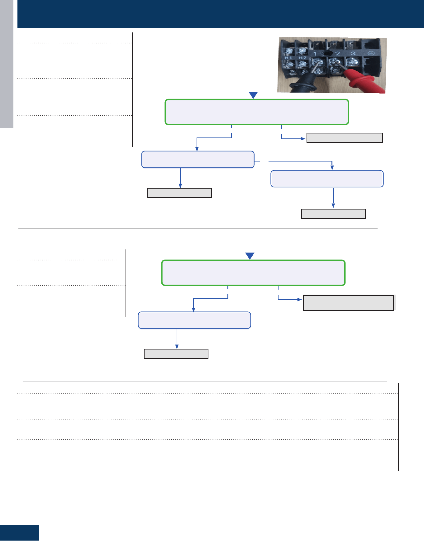
TROUBLESHOOTING & REFERENCES
G14
ENGLISH
No
Ye s
No
Refilling refrigerant
Start
Measure the current between 1/2
Is it 0.6A - 2.5A?
Replace the Coil
Ye s
Replace the PCB
Check the coil leakage
Check the coil leakage
Check the discharge refrigerant
Ye s
No
Start
Measure whether the detection of indoor unit coil temperature
sensor is accurate?
clen up the stuffs
Ye s
Replace the coil temperature
sensor
Check if there is any stuffs blocking
the air inlet
TROUBLESHOOTING FLOWCHARTS
Error Codes (Indoor/Outdoor)
E22/LED1: 21 Flash
IDU Anti-Frosting Protection
Possible Causes:
• Coil temperature sensor
• IDU air inlet blockage
Error Codes (Indoor/Outdoor)
F27/LED1: 21 Flash
Compressor Current Sampling Circuit Fault
Detection Conditions:
It is compressor block fault, the compressor will not work when this fault happen. It also can be self recovery when this fault happens.
Possible Causes:
• Ambient temperature is too low
• Compressor damage
Error Codes (Indoor/Outdoor)
LED1: 28 Flash
Lack of Refrigerant or
Discharging
Detection Conditions:
Compressor operation frequency
more than 46Hz,the current between
0.6A and 2.5A
Possible Causes:
• Coil leakage
• Discharge refrigerant
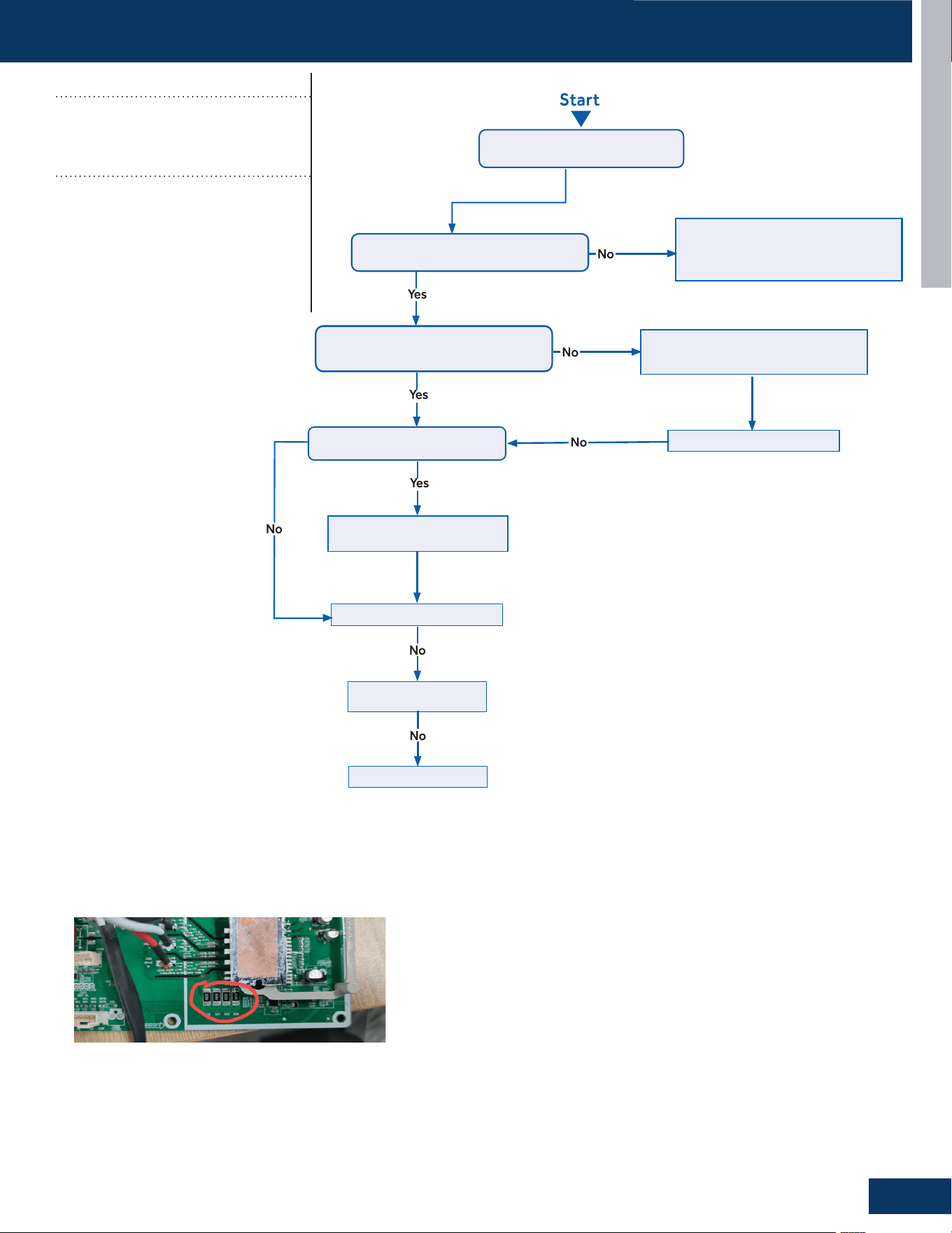
TROUBLESHOOTING & REFERENCES
G15
ENGLISH
Put through thepower and
turn onthe unit
Check whether the compressor
has stopped operation for more than3mins.
The time for stop operation is not enough and
the system's high pressure and low pressure
is unbalanced.
Please wait for 3mins and then
turn on the unit again.
Check whether the compressor wire
(UVW) is connected and the connection
sequenceis correct.
Please improve the connection betweenthe
control board and the compressorand then
connect it well
according tothe wiring diagram.
Check whether the charging
amount of refrigerant is too much.
Does the unit startedup normally?
Charge the refrigerant according to
the Service Manual.
Does the unit startedup normally?
Replace the control board
Eliminate malfunction?
Replace the compressor
Trigger condition
:
• The abnormal resistance value of R020 was collected, resulting in
the F2 error code occurs
TROUBLESHOOTING FLOWCHARTS
Error Codes (Indoor/Outdoor)
F2/LED1: 24 Flash
Module Operated Over Current
(Compressor Startup Failure)
Possible Causes:
• The power supply is abnormal
• Incorrect compressor wiring
• The power module is bad
• The compressor is bad
• System overload
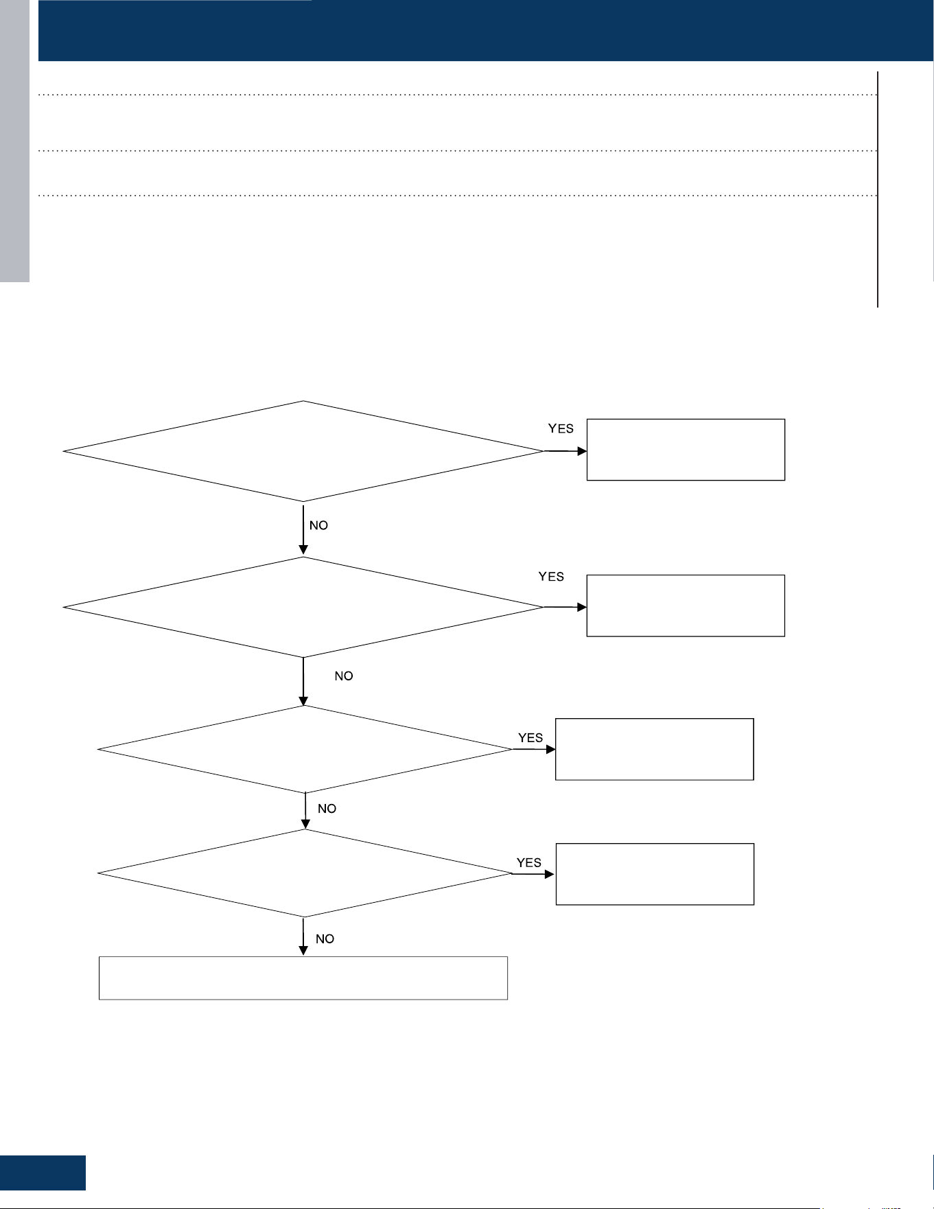
TROUBLESHOOTING & REFERENCES
G16
ENGLISH
Check if the wiring harness is damaged
Replace the wiring harness
Replace the leakage sensor
Check if the wiring harness has poor contact
Reconnect the wiring harness
Check if the PCB is damaged
Replace the PCB
Connect the leakage sensor
Check if the leakage sensor is disconnected with Indoor PCB
TROUBLESHOOTING FLOWCHARTS
Error Codes (Indoor)
bA
DIP Switch Enabled, No Sensor Detected
Detection Conditions:
DIP Switch Enabled, No Sensor Detected
Possible Causes:
• Loose wiring terminals
• Damaged wiring harness
• The leakage sensor is not connected
• PCB damage
* Caution
Be sure to turn o power switch before connect or disconnect connector, or else parts damage may be occurred.
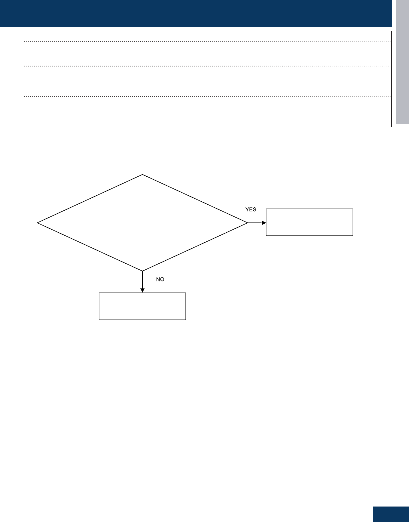
TROUBLESHOOTING & REFERENCES
G17
TROUBLESHOOTING FLOWCHARTS
ENGLISH
Check for refrigerant leakage
Replace the indoor unit or weld
the pipeline
Replace the leakage sensor
Error Codes (Indoor)
AA and Ab
Refrigerant Leakage Fault
Detection Conditions:
• AA: Refrigerant concentration over 10% LFL
• Ab: AA display after 5 minutes and refrigerant concentration of less than 8% LFL detected
Possible Causes:
• Pipe cracking
• The union nut is not secured
* Caution
Be sure to turn o power switch before connect or disconnect connector, or else parts damage may be occurred.

TROUBLESHOOTING & REFERENCES
G18
ENGLISH
Check if the wiring harness is damaged
Replace the wiring harness
Replace the leakage sensor
Check if the wiring harness has poor contact
Reconnect the wiring harness
Check if the PCB is damaged
Replace the PCB
TROUBLESHOOTING FLOWCHARTS
Error Codes (Indoor)
Ac
Leakage Sensor Communication Fault
Detection Conditions:
The communication between the leakage sensor and the PCB is faulty
Possible Causes:
• Loose wiring terminals
• Damaged wiring harness
• PCB damage
* Caution
Be sure to turn o power switch before connect or disconnect connector, or else parts damage may be occurred.
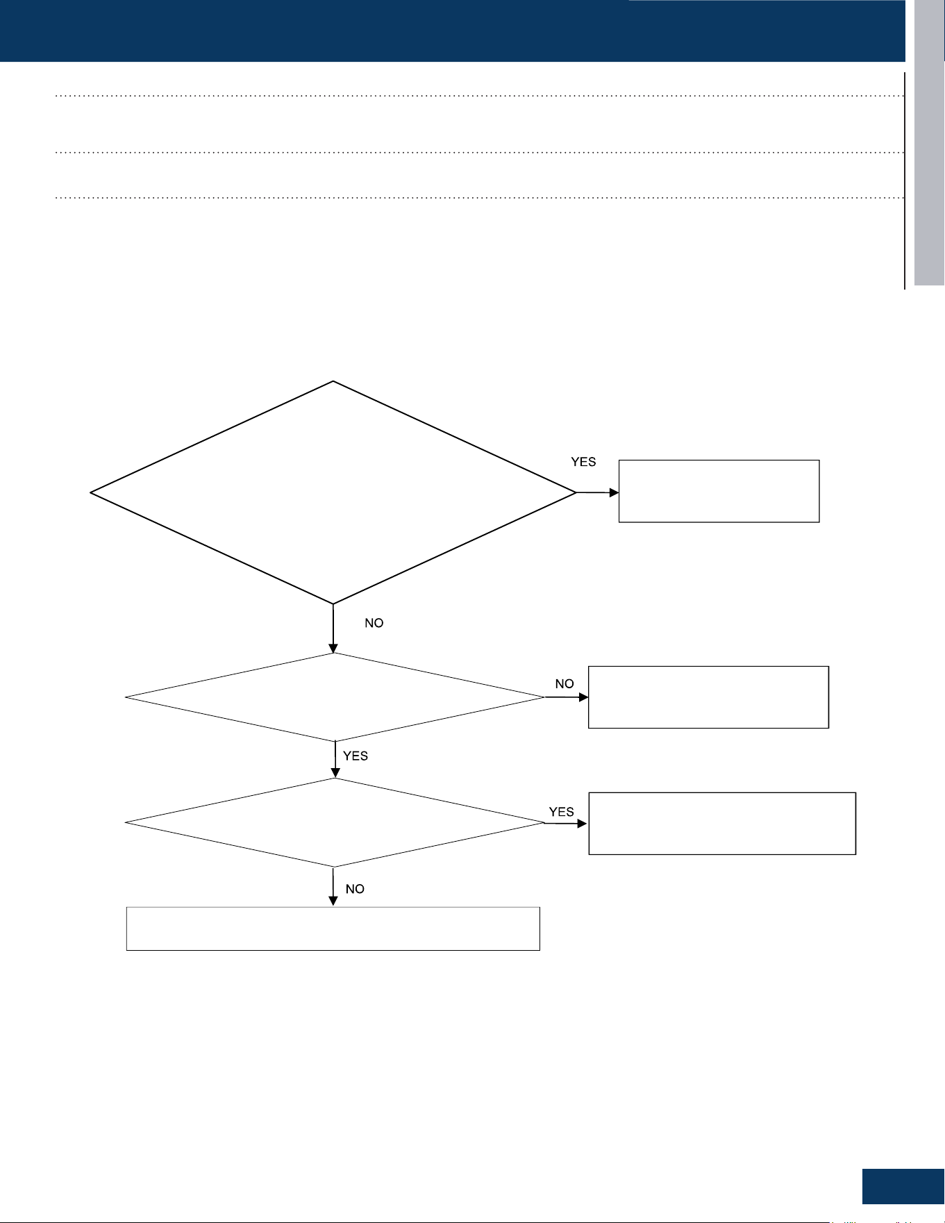
TROUBLESHOOTING & REFERENCES
G19
ENGLISH
Check if the sensor itself is damaged
Replace the leakage sensor
Replace the leakage sensor
Measure whether the sensor voltage is normal
Replace the PCB or leakage sensor
Check the temperature of the usage environment
Normal temperature range -35 to 80 degrees
Celsius
TROUBLESHOOTING FLOWCHARTS
Error Codes (Indoor)
Ad
Leakage Sensor Self-Check Fault
Detection Conditions:
Leakage sensor self-test failed
Possible Causes:
• Power supply overvoltage and undervoltage (5VDC)
• The temperature value detected by the leakage sensor exceeds the limit value
• Internal sensor error
* Caution
Be sure to turn o power switch before connect or disconnect connector, or else parts damage may be occurred.

TROUBLESHOOTING & REFERENCES
G20
ENGLISH
Check the actual usage time of the sensor
Actual usage time reaches 14.5 years
The unit power cycle
Replace the leakage sensor
TROUBLESHOOTING FLOWCHARTS
Error Codes (Indoor)
AE
Leakage Sensor Reaching-End-of-Life Warning
Detection Conditions:
The sensor is 6 months away from the end of its life
Possible Causes:
• The sensor approaching the end of life
• End of life counting error of sensor
* Caution
Be sure to turn o power switch before connect or disconnect connector, or else parts damage may be occurred.
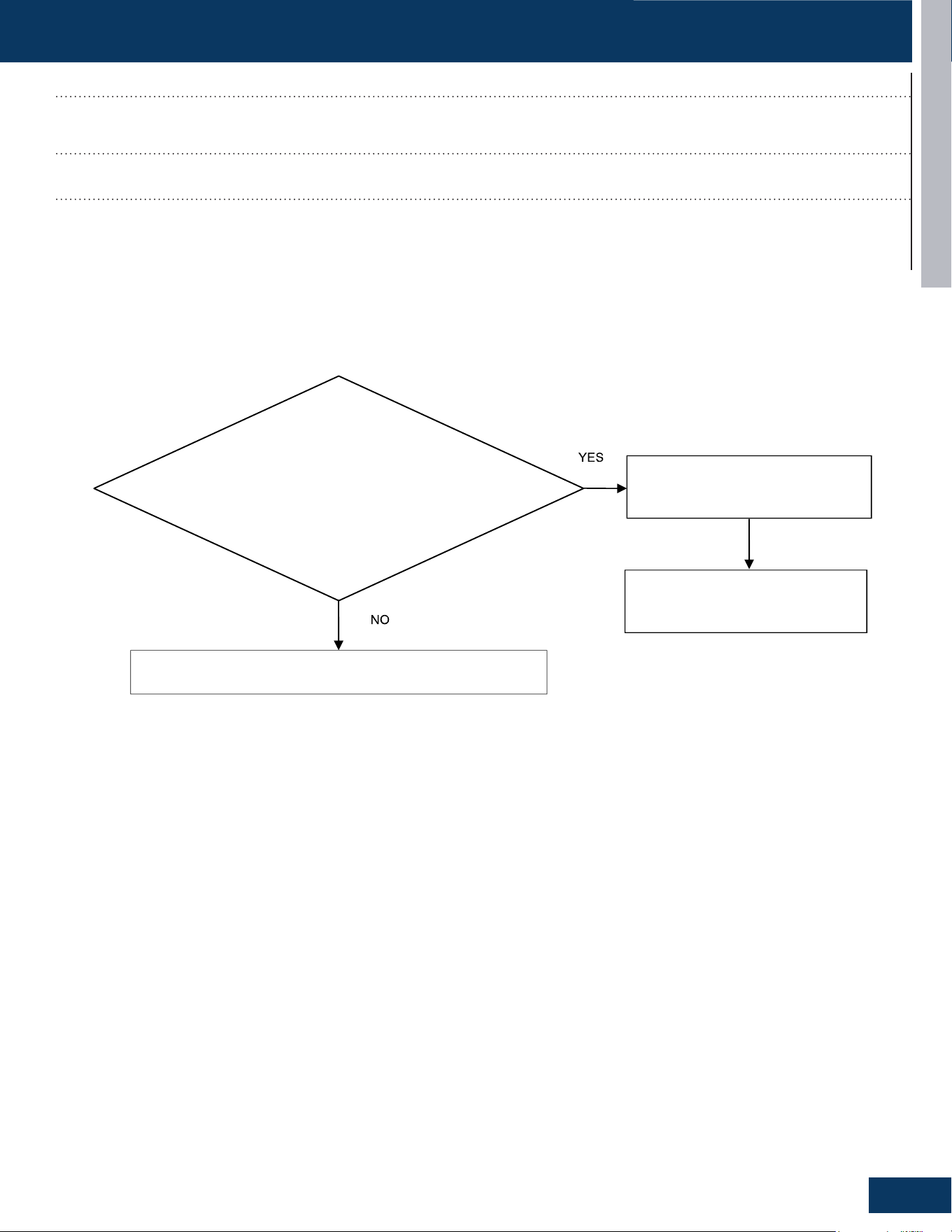
TROUBLESHOOTING & REFERENCES
G21
ENGLISH
Check the actual usage time of the sensor
Actual usage time reaches 15 years
The unit power cycle
Replace the leakage sensor
TROUBLESHOOTING FLOWCHARTS
Error Codes (Indoor)
AF
Leakage Sensor End- Of- Life
Detection Conditions:
The sensors have reached the end of life
Possible Causes:
• The sensor approaching the end of life
• End of life counting error of sensor
* Caution
Be sure to turn o power switch before connect or disconnect connector, or else parts damage may be occurred.
TROUBLESHOOTING & REFERENCES
G22
ENGLISH
SENSOR RESISTANCE TABLES
B25/50=3700K±3% R25=10KΩ±3%
Temp Resistance(KΩ) Temp Resistance(KΩ)
(°C) Rmax R (t) Normal Rmin (°C) Rmax R (t) Normal Rmin
-40 246.890 229.239 211.587 11 18.864 18.135 17.406
-39 233.754 217.183 200.612 12 18.039 17.354 16.669
-38 221.368 205.809 190.250 13 17.254 16.611 15.968
-37 209.686 195.075 180.464 14 16.507 15.903 15.299
-36 198.665 184.942 171.219 15 15.797 15.229 14.661
-35 188.265 175.375 162.485 16 15.120 14.587 14.054
-34 178.449 166.339 154.230 17 14.476 13.975 13.474
-33 169.181 157.803 146.426 18 13.862 13.392 12.922
-32 160.429 149.738 139.046 19 13.277 12.836 12.395
-31 152.162 142.114 132.067 20 12.720 12.306 11.892
-30 144.350 134.907 125.464 21 12.189 11.801 11.413
-29 136.519 127.675 118.831 22 11.683 11.319 10.955
-28 129.381 121.081 112.781 23 11.200 10.858 10.516
-27 122.638 114.849 107.060 24 10.739 10.419 10.099
-26 116.268 108.958 101.648 25 10.300 10.000 9.700
-25
110.249 103.388 96.527 26 9.894 9.600 9.306
-24 104.563 98.123 91.683 27 9.505 9.217 8.929
-23 99.190 93.144 87.098 28 9.134 8.852 8.570
-22 94.111 88.435 82.759 29 8.779 8.503 8.227
-21 89.311 83.982 78.653 30 8.441 8.170 7.899
-20 84.518 79.529 74.540 31 8.116 7.851 7.586
-19 80.484 75.785 71.086 32 7.805 7.546 7.287
-18 76.428 72.015 67.602 33 7.509 7.255 7.001
-17 72.591 68.447 64.303 34 7.225 6.976 6.727
-16 68.963 65.071 61.179 35 6.953 6.710 6.467
-15 65.530 61.874 58.218 36 6.692 6.454 6.216
-14 62.283 58.848 55.413 37 6.443 6.210 5.977
-13 59.210 55.983 52.756 38 6.204 5.976 5.748
-12 56.300 53.269 50.238 39 5.976 5.753 5.530
-11 53.547 50.699 47.851 40 5.756 5.538 5.320
-10 50.940 48.264 45.588 41 5.546 5.333 5.120
-9 48.472 45.957 43.442 42 5.345 5.136
4.927
-8 46.134 43.770 41.406 43 5.151 4.947 4.743
-7 43.918 41.697 39.476 44 4.967 4.767 4.567
-6 41.819 39.731 37.643 45 4.788 4.593 4.398
-5 39.830 37.868 35.906 46 4.618 4.427 4.236
-4 37.944 36.100 34.256 47 4.455 4.268 4.081
-3 36.157 34.423 32.689 48 4.298 4.115 3.932
-2 34.462 32.832 31.202 49 4.147 3.968 3.789
-1 32.854 31.322 29.790 50 4.004 3.829 3.654
TROUBLESHOOTING & REFERENCES
G23
ENGLISH
SENSOR RESISTANCE TABLES
B25/50=3700K±3% R25=10KΩ±3%
Temp Resistance(KΩ) Temp Resistance(KΩ)
(°C) Rmax R (t) Normal Rmin (°C) Rmax R (t) Normal Rmin
0 31.362 29.920 28.478 51 3.863 3.692 3.521
1 29.881 28.527 27.173 52 3.729 3.562 3.395
2 28.507 27.234 25.961 53 3.601 3.438 3.275
3 27.202 26.006 24.810 54 3.478 3.318 3.158
4 25.965 24.840 23.715 55 3.359 3.203 3.047
5 24.788 23.731 22.674 56 3.246 3.093 2.940
6 23.672 22.678 21.684 57 3.136 2.987 2.838
7 22.610 21.676 20.742 58 3.031 2.885 2.739
8 21.601 20.723 19.845 59 2.930 2.787 2.644
9 20.642 19.817 18.992 60 2.833 2.693 2.553
10 19.730 18.955 18.180 61 2.739 2.602 2.465
62 2.649 2.515 2.381 84 1.321 1.238 1.155
63 2.562 2.431 2.300 85 1.281 1.200 1.119
64 2.478 2.350 2.222 86 1.244 1.165 1.086
65 2.398 2.273 2.148 87 1.209 1.131 1.053
66
2.320 2.198 2.076 88 1.173 1.097 1.021
67 2.246 2.126 2.006 89 1.140 1.065 0.990
68 2.174 2.057 1.940 90 1.107 1.034 0.961
69 2.104 1.990 1.876 91 1.076 1.004 0.932
70 2.038 1.926 1.814 92 1.045 0.975 0.905
71 1.974 1.864 1.754 93 1.016 0.947 0.878
72 1.912 1.805 1.698 94 0.987 0.920 0.853
73 1.853 1.748 1.643 95 0.960 0.894 0.828
74 1.795 1.692 1.589 96 0.934 0.869 0.804
75 1.739 1.639 1.539 97 0.907 0.844 0.781
76 1.686 1.588 1.490 98 0.883 0.821 0.759
77 1.634 1.538 1.442 99 0.859 0.798 0.737
78 1.585 1.491 1.397 100 0.836 0.776 0.716
79 1.537 1.445 1.353 101 0.814 0.755 0.696
80 1.490 1.400 1.310 102 0.791 0.734 0.677
81 1.445 1.357 1.269 103 0.771 0.715 0.659
82 1.402 1.316 1.230 104 0.750 0.695
0.640
83 1.361 1.276 1.191 105 0.731 0.677 0.623
TROUBLESHOOTING & REFERENCES
G24
ENGLISH
SENSOR RESISTANCE TABLES
B25/50=4200K±1%, R25
O
C=23KΩ±2%
Temp Resistance(KΩ) Temp Resistance(KΩ)
(°C) Rmax R (t) Normal Rmin (°C) Rmax R (t) Normal Rmin
-30.0 511.383 487.031 462.680 18.0 32.935 32.169 31.403
-29.0 478.574 456.022 433.470 19.0 31.351 30.638 29.925
-28.0 448.361 427.455 406.549 20.0 29.850 29.187 28.524
-27.0 420.230 400.844 381.458 21.0 28.430 27.813 27.196
-26.0 394.026 376.044 358.062 22.0 27.086 26.512 25.938
-25.0 369.606 352.922 336.238 23.0 25.811 25.278 24.745
-24.0 346.838 331.355 315.872 24.0 24.604 24.109 23.614
-23.0 325.602 311.229 296.856 25.0 23.460 23.000 22.540
-22.0 305.786 292.440 279.094 26.0 22.397 21.948 21.499
-21.0 287.287 274.892 262.497 27.0 21.387 20.950 20.513
-20.0 269.723 258.221 246.718 28.0 20.429 20.003 19.577
-19.0 253.871 243.171 232.471 29.0 19.521 19.105 18.689
-18.0 238.784 228.840 218.896 30.0 18.656 18.251 17.846
-17.0 224.677 215.433 206.189 31.0 17.835 17.440 17.045
-16.0 211.482 202.887 194.292 32.0 17.054 16.670
16.286
-15.0 199.133 191.140 183.147 33.0 16.313 15.938 15.563
-14.0 187.574 180.139 172.704 34.0 15.608 15.243 14.878
-13.0 176.749 169.832 162.915 35.0 14.936 14.581 14.226
-12.0 166.607 160.171 153.735 36.0 14.299 13.953 13.607
-11.0 157.103 151.113 145.123 37.0 13.691 13.354 13.017
-10.0 148.191 142.616 137.041 38.0 13.113 12.785 12.457
-9.0 139.834 134.644 129.454 39.0 12.563 12.243 11.923
-8.0 131.993 127.161 122.329 40.0 12.038 11.727 11.416
-7.0 124.634 120.134 115.634 41.0 11.539 11.236 10.933
-6.0 117.724 113.534 109.344 42.0 11.063 10.768 10.473
-5.0 111.235 107.332 103.429 43.0 10.611 10.323 10.035
-4.0 105.139 101.503 97.867 44.0 10.178 9.898 9.618
-3.0 99.408 96.021 92.634 45.0 9.766 9.493 9.220
-2.0 94.022 90.866 87.710 46.0 9.373 9.107 8.841
-1.0 88.955 86.015 83.075 47.0 8.998 8.739 8.480
0.0 84.220 81.479 78.739 48.0 8.640 8.388 8.136
1.0 79.704 77.151 74.598 49.0 8.299 8.053 7.807
2.0 75.481 73.102 70.723 50.0 7.974 7.734 7.495
3.0 71.505 69.288 67.071 51.0 7.661 7.428 7.195
4.0 67.759 65.693 63.627 52.0 7.363 7.136 6.909
5.0 64.230 62.304 60.378 53.0 7.079 6.858 6.637
6.0 60.903 59.108 57.313 54.0 6.807 6.592 6.377
7.0 57.767 56.094 54.421 55.0 6.547 6.337 6.127
8.0 54.808 53.249 51.690 56.0 6.300 6.095 5.890
9.0 52.017 50.564 49.111 57.0 6.061 5.862 5.663
10.0 49.383 48.029 46.675 58.0 5.834 5.640 5.446
11.0 46.896 45.635 44.374 59.0 5.617 5.428 5.239
12.0 44.548 43.373 42.198 60.0 5.410 5.225 5.040
13.0 42.331 41.236 40.141 61.0 5.210 5.030 4.850
14.0 40.235 39.215 38.195 62.0 5.019 4.844 4.669
15.0 38.254 37.304 36.354 63.0 4.837 4.666 4.495
16.0 36.381 35.497 34.613 64.0 4.662 4.495 4.328
17.0 34.611 33.788 32.965 65.0 4.494 4.332 4.170
TROUBLESHOOTING & REFERENCES
G25
ENGLISH
SENSOR RESISTANCE TABLES
B25/50=4200K±1%, R25
O
C=23KΩ±2%
Temp Resistance(KΩ) Temp Resistance(KΩ)
(°C) Rmax R (t) Normal Rmin (°C) Rmax R (t) Normal Rmin
66.0 4.333 4.175 4.017 86.0 2.182 2.085 1.988
67.0 4.179 4.025 3.871 87.0 2.112 2.017 1.922
68.0 4.032 3.881 3.730 88.0 2.046 1.953 1.860
69.0 3.890 3.743 3.596 89.0 1.981 1.890 1.799
70.0 3.754 3.611 3.468 90.0 1.919 1.830 1.741
71.0 3.624 3.484 3.344 91.0 1.859 1.772 1.685
72.0 3.498 3.362 3.226 92.0 1.801 1.716 1.631
73.0 3.378 3.245 3.112 93.0 1.745 1.662 1.579
74.0 3.263 3.133 3.003 94.0 1.691 1.610 1.529
75.0 3.153 3.026 2.899 95.0 1.639 1.560 1.481
76.0 3.046 2.922 2.798 96.0 1.589 1.512 1.435
77.0 2.944 2.823 2.702 97.0 1.540 1.465 1.390
78.0 2.845 2.727 2.609 98.0 1.494 1.420 1.346
79.0 2.751 2.636 2.521 99.0 1.449 1.377 1.305
80.0 2.659 2.547 2.435 100.0 1.406 1.335
1.264
81.0 2.573 2.463 2.353 101.0 1.363 1.294 1.225
82.0 2.488 2.381 2.274 102.0 1.322 1.255 1.188
83.0 2.407 2.303 2.199 103.0 1.283 1.217 1.151
84.0 2.329 2.227 2.125 104.0 1.244 1.180 1.116
85.0 2.253 2.154 2.054 105.0 1.208 1.145 1.082

TROUBLESHOOTING & REFERENCES
G26
ENGLISH
SENSOR RESISTANCE TABLES
B25/80=4450K±3% R80=50KΩ±3%
Temp Resistance(KΩ) Temp Resistance(KΩ)
(°C) Rmax R (t) Normal Rmin (°C) Rmax R (t) Normal Rmin
-40 23982.342 21280.977 18579.613 11 1126.419 1041.293 956.167
-39 22397.462 19890.917 17384.372 12 1067.463 987.477 907.491
-38 20925.744 18599.155 16272.567 13 1011.977 936.799 861.621
-37 19558.506 17398.211 15237.916 14 959.732 889.052 818.372
-36 18287.777 16281.212 14274.647 15 910.510 844.042 777.574
-35 17106.237 15241.843 13377.450 16 864.114 801.590 739.066
-34 16007.159 14274.298 12541.437 17 820.361 761.533 702.705
-33 14984.359 13373.234 11762.109 18 779.081 723.717 668.353
-32 14032.148 12533.735 11035.322 19 740.117 688.001 635.885
-31 13145.291 11751.273 10357.255 20 703.323 654.254 605.185
-30 12318.968 11021.678 9724.388 21 668.565 622.355 576.145
-29 11551.311 10343.407 9135.504 22 635.715 592.189 548.663
-28 10835.229 9710.234 8585.239 23 604.657 563.651 522.645
-27 10167.003 9118.935 8070.867 24 575.282 536.644 498.006
-26 9543.200 8566.532 7589.865 25 547.490 511.076 474.662
-25
8960.652 8050.276 7139.901 26 521.186 486.862 452.538
-24 8416.430 7567.624 6718.818 27 496.281 463.922 431.563
-23 7907.828 7116.224 6324.620 28 472.693 442.182 411.671
-22 7432.345 6693.901 5955.457 29 450.344 421.572 392.800
-21 6987.666 6298.642 5609.618 30 429.165 402.028 374.891
-20 6571.650 5928.583 5285.516 31 409.087 383.489 357.891
-19 6187.164 5586.374 4985.585 32 390.047 365.898 341.749
-18 5826.712 5265.313 4703.915 33 371.986 349.201 326.416
-17 5488.692 4964.004 4439.315 34 354.850 333.349 311.848
-16 5171.616 4681.148 4190.680 35 338.586 318.295 298.004
-15 4874.100 4415.539 3956.978 36 323.147 303.995 284.843
-14 4594.858 4166.054 3737.249 37 308.485 290.407 272.329
-13 4332.694 3931.647 3530.600 38 294.559 277.493 260.427
-12 4086.494 3711.346 3336.198 39 281.328 265.216 249.104
-11 3855.222 3504.244 3153.266 40 268.753 253.541 238.329
-10 3637.915 3309.498 2981.082 41 256.801 242.437 228.073
-9 3433.673 3126.321 2818.969 42 245.438 231.873 218.308
-8 3241.661 2953.980 2666.299 43 234.630 221.820 209.010
-7 3061.098 2791.790 2522.482 44 224.350 212.252 200.154
-6 2891.257 2639.114 2386.971 45 214.569 203.142 191.715
-5 2731.460 2495.357 2259.253 46 205.260 194.467 183.674
-4 2581.076 2359.962 2138.848 47 196.399 186.204 176.009
-3 2439.514 2232.412 2025.310 48 187.963 178.333 168.703
-2 2306.222 2112.221 1918.220 49 179.929 170.832 161.735
-1 2180.688 1998.938 1817.187 50 172.275 163.682 155.089
0 2094.972 1921.993 1749.014 51 164.984 156.866 148.748
1 1975.099 1813.265 1651.431 52 158.036 150.367 142.698
2 1863.127 1711.646 1560.165 53 151.412 144.168 136.924
3 1758.449 1616.593 1474.737 54 145.099 138.255 131.411
4 1660.513 1527.611 1394.709 55 139.078 132.613 126.148
5 1568.817 1444.250 1319.683 56 133.336 127.229 121.122
6 1482.897 1366.096 1249.295 57 127.858 122.089 116.320
7 1402.336 1292.773 1183.210 58 122.630 117.181 111.732
TROUBLESHOOTING & REFERENCES
G27
ENGLISH
SENSOR RESISTANCE TABLES
B25/80=4450K±3% R80=50KΩ±3%
Temp Resistance(KΩ) Temp Resistance(KΩ)
(°C) Rmax R (t) Normal Rmin (°C) Rmax R (t) Normal Rmin
8 1326.746 1223.935 1121.124 59 117.641 112.494 107.347
9 1255.774 1159.265 1062.756 60 112.879 108.018 103.157
10 1189.098 1098.474 1007.850 61 108.332 103.741 99.150
62 103.989 99.654 95.319 107 20.667 19.720 18.773
63 99.841 95.748 91.655 108 20.020 19.091 18.162
64 95.879 92.014 88.149 109 19.397 18.485 17.573
65 92.091 88.443 84.795 110 18.795 17.900 17.005
66 88.472 85.028 81.584 111 18.215 17.337 16.459
67 85.011 81.761 78.511 112 17.655 16.793 15.931
68 81.703 78.636 75.569 113 17.114 16.268 15.422
69 78.538 75.645 72.752 114 16.593 15.763 14.933
70 75.510 72.781 70.052 115 16.090 15.275 14.460
71 72.614 70.040 67.466 116 15.603 14.804 14.005
72 69.842 67.415 64.988 117 15.133 14.349 13.565
73 67.189 64.901 62.613 118 14.681 13.911 13.141
74
64.649 62.493 60.337 119 14.243 13.488 12.733
75 62.216 60.185 58.154 120 13.821 13.080 12.339
76 59.886 57.973 56.060 121 13.412 12.685 11.958
77 57.653 55.852 54.051 122 13.019 12.305 11.591
78 55.515 53.820 52.125 123 12.638 11.938 11.238
79 53.465 51.870 50.275 124 12.271 11.584 10.897
80 51.500 50.000 48.500 125 11.917 11.242 10.567
81 49.684 48.206 46.728 126 11.573 10.911 10.249
82 47.940 46.484 45.028 127 11.243 10.593 9.943
83 46.267 44.832 43.397 128 10.923 10.285 9.647
84 44.659 43.246 41.833 129 10.614 9.988 9.362
85 43.114 41.723 40.332 130 10.315 9.701 9.087
86 41.629 40.260 38.891 131 10.028 9.425 8.822
87 40.203 38.856 37.509 132 9.750 9.158 8.566
88 38.831 37.506 36.181 133 9.481 8.900 8.319
89 37.513 36.209 34.905 134 9.222 8.651 8.080
90 36.244 34.962 33.680 135 8.972 8.411 7.850
91 35.025 33.764 32.503 136 8.731 8.180 7.629
92 33.851 32.612 31.373 137 8.498 7.957 7.416
93 32.722 31.504 30.286 138 8.273 7.741 7.209
94 31.636 30.439 29.242 139 8.055 7.533 7.011
95 30.590 29.413 28.236 140 7.846 7.333 6.820
96 29.583 28.427 27.271 141 7.628 7.125 6.621
97 28.614 27.478 26.342 142 7.417 6.923 6.429
98 27.680 26.564 25.448 143 7.213 6.728 6.243
99 26.781 25.685 24.589 144 7.014 6.538 6.062
100 25.914 24.838 23.762 145 6.822 6.355 5.888
101 25.080 24.023 22.966 146 6.636 6.178 5.719
102 24.275 23.237 22.199 147 6.455 6.006 5.556
103 23.500 22.481 21.462 148 6.280 5.839 5.398
104 22.753 21.752 20.751 149 6.111 5.678 5.244
105 22.031 21.049 20.067 150 5.946 5.521 5.096
106 21.336 20.372 19.408
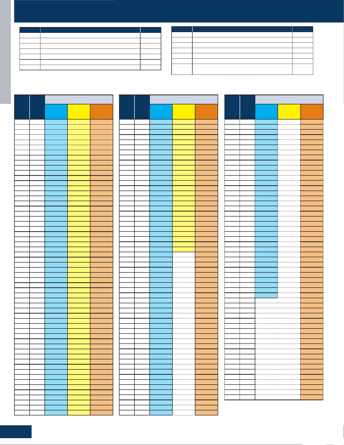
TROUBLESHOOTING & REFERENCES
G28
ENGLISH
SENSOR RESISTANCE VALUES
Abbr. Denition Type
tAo Temperature of outdoor ambient 10K
tc Temperature of outdoor condenser 10K
td Temperature of outdoor discharge 50K
tE Temperature of outdoor defrost 10K
tS Temperature of outdoor suction 10K
tdr Temperature of compressor driver module 10K
Idr Current of the compressor 10K
Abbr. Denition Type
tAI Temperature of indoor ambient 10K
TCI Temperature of indoor condenser 10K
Toci Hot Gas Leaving the 4-Way Valve 10K
Tc 2 EEV Liquid Sensor 10K
Tc 1 EEV Gas Sensor 10K
Tm Module Temp Sensor 10K
TAI Temperature of indoor ambient (9K/12K Tempo &
All CAC)
23K
10K Sensors: Ambient (all except ducted, cassette, and 9K-12K Tempo) suction, gas, defrost, and pipe sensors.
23K Sensors: Ambient sensors for ducted, cassette, and 9K-12K Tempo
50K Sensors: Discharge sensors
°F °C
Normal (KΩ)
10K
SENSORS
23K
SENSORS
50K
SENSORS
-22 -30 147.95 513.115 12061.74
-20.2 -29 139.56 478.894 11267.87
-18.4 -28 131.70 447.408 10531.37
-16.6 -27 124.34 418.379 9847.72
-14.8 -26 117.44 391.564 9212.81
-13 -25 110.96 366.751 8622.85
-11.2 -24 104.89 343.754 8074.38
-9.4 -23 99.19 322.407 7564.22
-7.6 -22 93.83 302.567 7089.47
-5.8 -21 88.80 284.105 6647.45
-4 -20 84.07 266.905 6235.71
-2.2 -19 79.62 250.866 5851.99
-0.4 -18 75.44 235.895 5494.21
1.4 -17 71.50 221.911 5160.46
3.2 -16 67.79 208.838 4849.00
5 -15 64.30 196.609 4558.19
6.8 -14 61.01 185.163 4286.55
8.6 -13 57.91 174.443 4032.71
10.4 -12 54.99 164.399 3795.39
12.2 -11 52.23 154.983 3573.43
14 -10 49.62 146.153 3365.73
15.8 -9 47.17 137.87 3171.31
17.6 -8 44.85 130.096 2989.25
19.4 -7 42.65 122.799 2818.67
21.2 -6 40.58 115.946 2658.81
23 -5 38.62 109.51 2508.91
24.8 -4 36.77 103.462 2368.32
26.6 -3 35.01 97.779 2236.39
28.4 -2 33.36 92.437 2112.55
30.2 -1 31.78 87.415 1996.25
32 0 30.30 82.691 1887.00
33.8 1 28.89 78.248 1784.33
35.6 2 27.55 74.067 1687.81
37.4 3 26.29 70.133 1597.04
39.2 4 25.09 66.43 1511.65
41 5 23.95 62.943 1431.28
42.8 6 22.87 59.659 1355.62
44.6 7 21.84 56.566 1284.36
46.4 8 20.87 53.651 1217.23
48.2 9 19.94 50.904 1153.96
50 10 19.06 48.314 1094.32
51.8 11 18.23 45.872 1038.07
53.6 12 17.43 43.569 985.01
55.4 13 16.68 41.395 934.94
57.2 14 15.96 39.343 887.68
59 15 15.28 37.406 843.05
60.8 16 14.63 35.577 800.89
62.6 17 14.01 33.848 761.06
64.4 18 13.42 32.215 723.41
66.2 19 12.86 30.671 687.82
68 20 12.32 29.21 654.16
69.8 21 11.81 27.828
622.32
71.6 22 11.33 26.521 592.18
73.4 23 10.86 25.283 563.66
75.2 24 10.42 24.111 536.65
77 25 10.00 23 511.08
78.8 26 9.60 21.947 486.94
80.6 27 9.21 20.949 464.05
°F °C
Normal (KΩ)
10K
SENSORS
23K
SENSORS
50K
SENSORS
82.4 28 8.85 20.003 442.35
84.2 29 8.50 19.104 421.77
86 30 8.16 18.252 402.24
87.8 31 7.84 17.442 383.72
89.6 32 7.54 16.674 366.13
91.4 33 7.25 15.943 349.43
93.2 34 6.97 15.249 333.58
95 35 6.70 14.588 318.52
96.8 36 6.45 13.96 304.22
98.6 37 6.20 13.362 290.62
100.4 38 5.97 12.794 277.70
102.2 39 5.75 12.252 265.41
104 40 5.53 11.736 253.73
105.8 41 5.33 11.244 242.62
107.6 42 5.13 10.776 232.04
109.4 43 4.94 10.329 221.98
111.2 44 4.76 9.904 212.41
113 45 4.59 9.497 203.29
114.8 46 4.43 9.11 194.61
116.6 47 4.27 8.74 186.34
118.4 48 4.11 8.387 178.46
120.2 49 3.97 8.05 170.95
122 50 3.83 7.728 163.80
123.8 51 3.69 7.421 156.97
125.6 52 3.57 7.127 150.47
127.4 53 3.44 6.846 144.26
129.2 54 3.32 138.35
131 55 3.21 132.70
132.8 56 3.10 127.31
134.6 57 2.99 122.16
136.4 58 2.89 117.25
138.2 59 2.79 112.56
140 60 2.70 108.08
141.8 61 2.61 103.80
143.6 62 2.52 99.70
145.4 63 2.44 95.79
147.2 64 2.36 92.06
149 65 2.28 88.48
150.8 66 2.21 85.06
152.6 67 2.14 81.79
154.4 68 2.07 78.66
156.2 69 2.00 75.67
158 70 1.94 72.80
159.8 71 1.88 70.06
161.6 72 1.82 67.43
163.4 73 1.76 64.91
165.2 74 1.71 62.50
167 75 1.65 60.19
168.8 76 1.60 57.98
170.6 77 1.55 55.86
172.4 78 1.51 53.82
174.2 79 1.46 51.87
176 80 1.41 50.00
177.8 81 1.37 48.21
179.6 82 1.33 46.48
181.4 83 1.29 44.83
183.2 84 1.25 43.25
185 85 1.22 41.72
°F °C
Normal (KΩ)
10K
SENSORS
23K
SENSORS
50K
SENSORS
186.8 86 1.18 40.26
188.6 87 1.14 38.85
190.4 88 1.11 37.50
192.2 89 1.08 36.21
194 90 1.05 34.96
195.8 91 1.02 33.77
197.6 92 0.99 32.62
199.4 93 0.96 31.51
201.2 94 0.93 30.45
203 95 0.91 29.42
204.8 96 0.88 28.44
206.6 97 0.86 27.50
208.4 98 0.83 26.59
210.2 99 0.81 25.71
212 100 0.79 24.87
213.8 101 0.76 24.06
215.6 102 0.74 23.28
217.4 103 0.72 22.52
219.2 104 0.70 21.80
221 105 0.68 21.10
222.8 106 0.67 20.43
224.6 107 0.65 19.78
226.4 108 0.63 19.16
228.2 109 0.61 18.56
230 110 0.60 17.98
231.8 111 0.58 17.42
233.6 112 0.57 16.88
235.4 113 0.55 16.36
237.2 114 0.54 15.85
239 115 0.52 15.37
240.8 116 0.51 14.90
242.6
117 0.50 14.45
244.4 118 0.48 14.01
246.2 119 0.47 13.59
248 120 0.46 13.19
249.8 121 12.80
251.6 122 12.42
253.4 123 12.05
255.2 124 11.70
257 125 11.35
258.8 126 11.02
260.6 127 10.70
262.4 128 10.40
264.2 129 10.10
266 130 9.81
267.8 131 9.53
269.6 132 9.26
271.4 133 9.00
273.2 134 8.74
275 135 8.50
276.8 136 8.26
278.6 137 8.03
280.4 138 7.81
282.2 139 7.60
284 140 7.39

[This page intentionally left blank.]
Rev. 10-16-25
©Copyright 2025 GE Appliances, a Haier Company.
Our continued commitment to quality products may
mean a change in specications without notice.
Ductless Technical Support
Phone: 866.814.3633
Email: HVACSupport@GEAppliances.com
Online: GEAppliancesAirAndWater.com