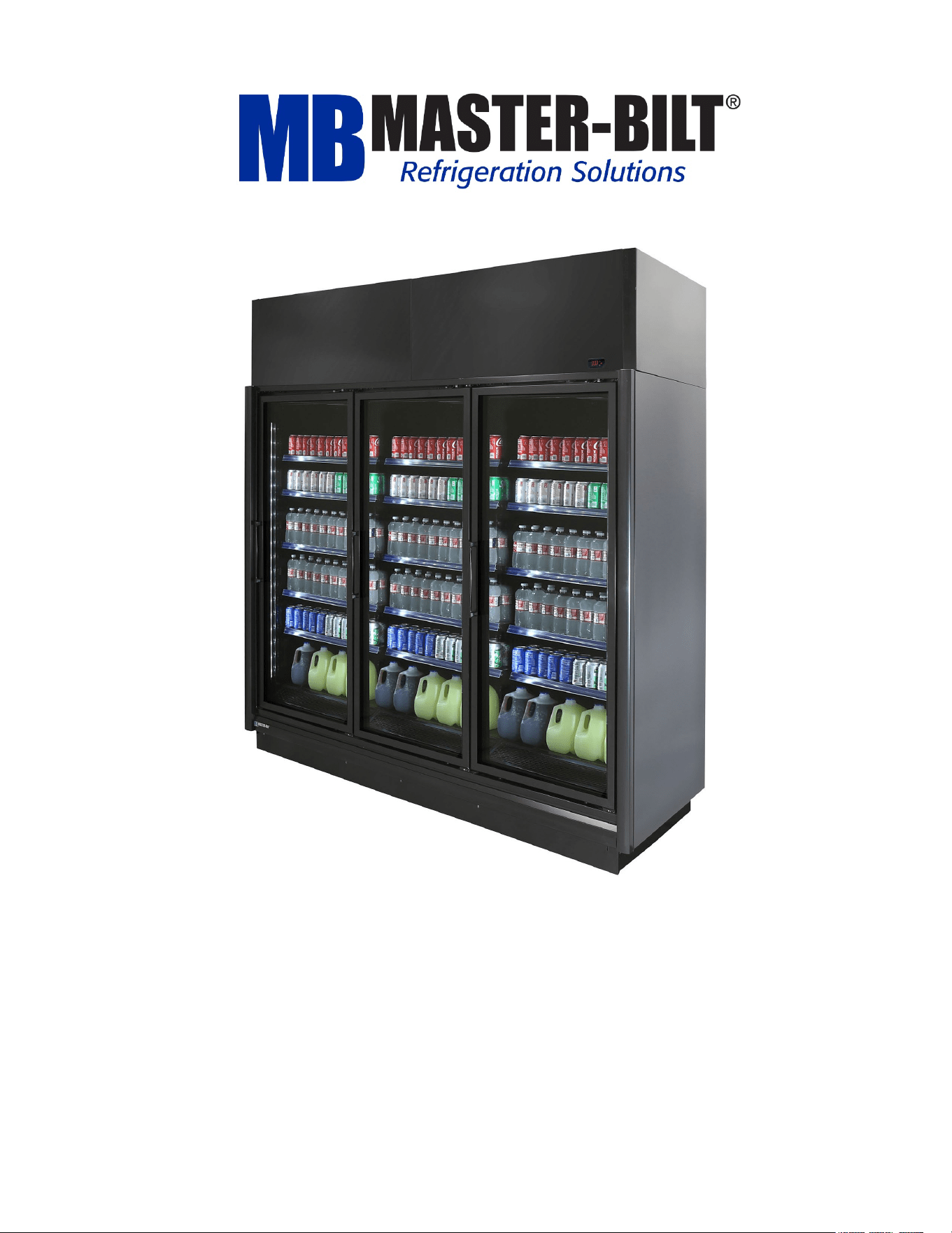
BEL/BEM-CU Series
Installation & Operations Manual
Master-Bilt Products
908 Highway 15 North
New Albany, MS 38652
Phone: (800) 684-8988

102167
- Rev. B All specifications within this publication subject to change without notice. © 2025 Master-Bilt Products, LLC. All rights reserved. 2
TABLE OF CONTENTS
INTRODUCTION .............................................................................................................................................................3
WARNING LABELS AND SAFETY INSTRUCTIONS ....................................................................................................4
PRE-INSTALLATION INSTRUCTIONS ..........................................................................................................................5
INSTRUCTIONS ON DELIVERY ..............................................................................................................................5
PACKING LIST AND LOCATION OF ITEMS ............................................................................................................5
INSPECTION FOR SHIPPING DAMAGE .................................................................................................................6
INSTALLATION INSTRUCTIONS ...................................................................................................................................7
GENERAL INSTRUCTIONS .....................................................................................................................................7
STORE CONDITIONS ..............................................................................................................................................7
LOCATION ................................................................................................................................................................7
LEVELING .............................................................................................................................................................. 10
JOINING MULTIPLE SECTIONS ........................................................................................................................... 10
DOOR ADJUSTMENT ........................................................................................................................................... 11
PLUMBING ............................................................................................................................................................. 12
INSTALLING THE KICKPLATE.............................................................................................................................. 14
INSTALLING JOINING TRIM ................................................................................................................................. 14
REMOVING AND REPLACING THE ENDS .......................................................................................................... 15
INSTALLING SHROUDS ....................................................................................................................................... 16
INSTALLING REAR CLOSEOFF AND ENDSKIRTS ............................................................................................. 17
INSTALLING CONDENSING UNIT AND WIRING ................................................................................................. 18
INSTALLING SHELVES, CLEANOUT PAN, AND WIRE BOTTOM SHELF .......................................................... 19
REFRIGERATION SYSTEM EVACUATING AND CHARGING ............................................................................. 20
MASTER-BILT ELECTRONIC REFRIGERATION CONTROL OPERATION ............................................................ 21
DISPLAY ................................................................................................................................................................ 22
ADDITIONAL INFO ...................................................................................................................................................... 23
STARTING PROCEDURE............................................................................................................................................ 25
DOOR PLASTIC (GASKET RETAINER) REPLACEMENT .................................................................................... 27
DOOR GASKET REPLACEMENT ......................................................................................................................... 27
DOOR HEATER REPLACEMENT ......................................................................................................................... 27
SERVICE INSTRUCTIONS (Trouble Shooting Guide) .............................................................................................. 28
TECHNICIAN’S CONDISERATIONS: ......................................................................................................................... 29
MASTER-BILT PART NUMBERS ............................................................................................................................... 31
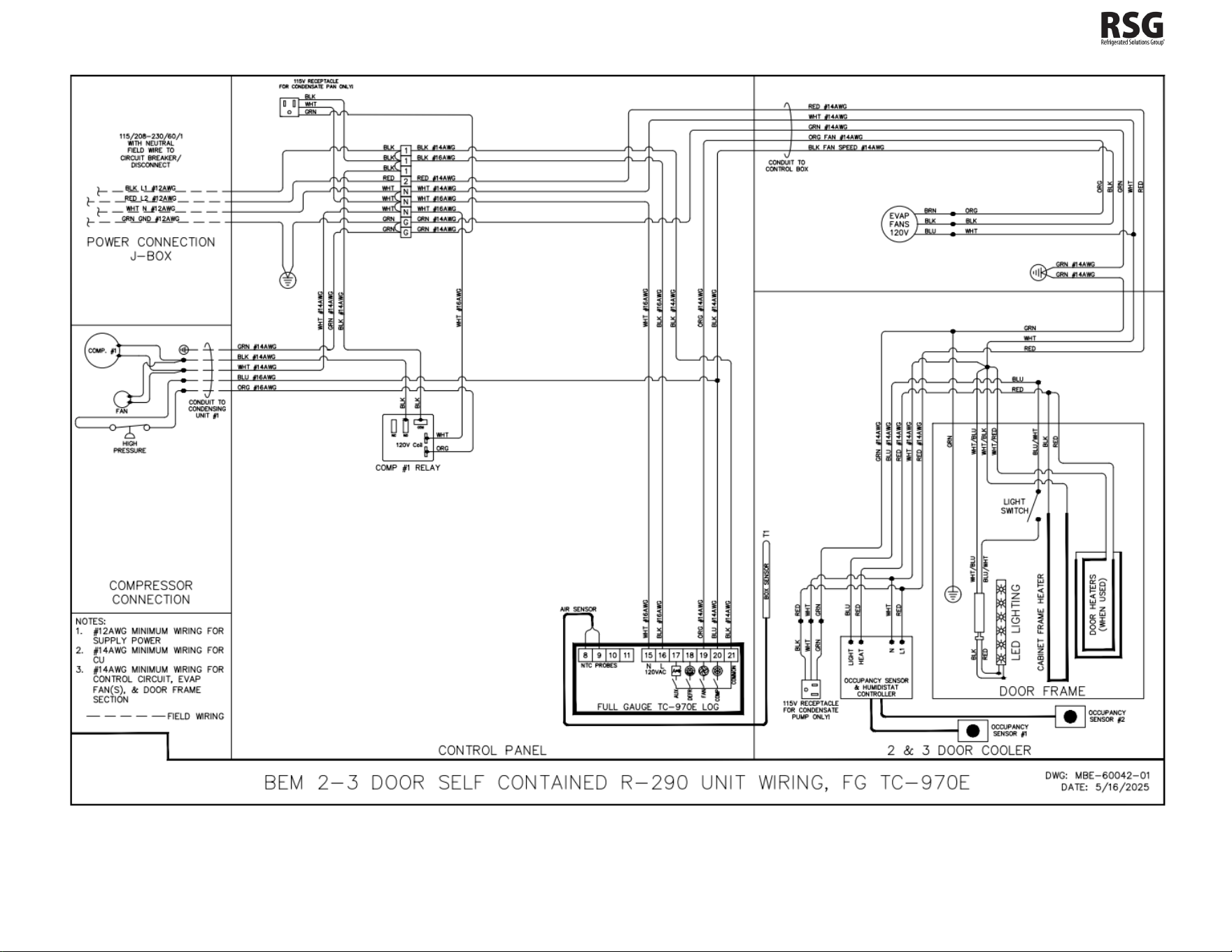
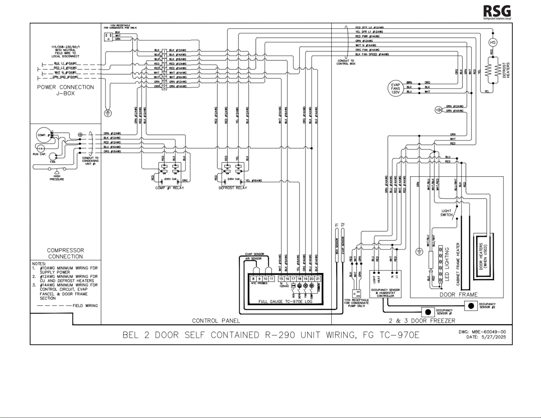
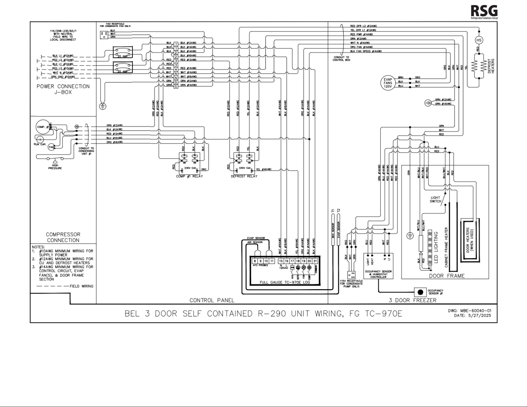
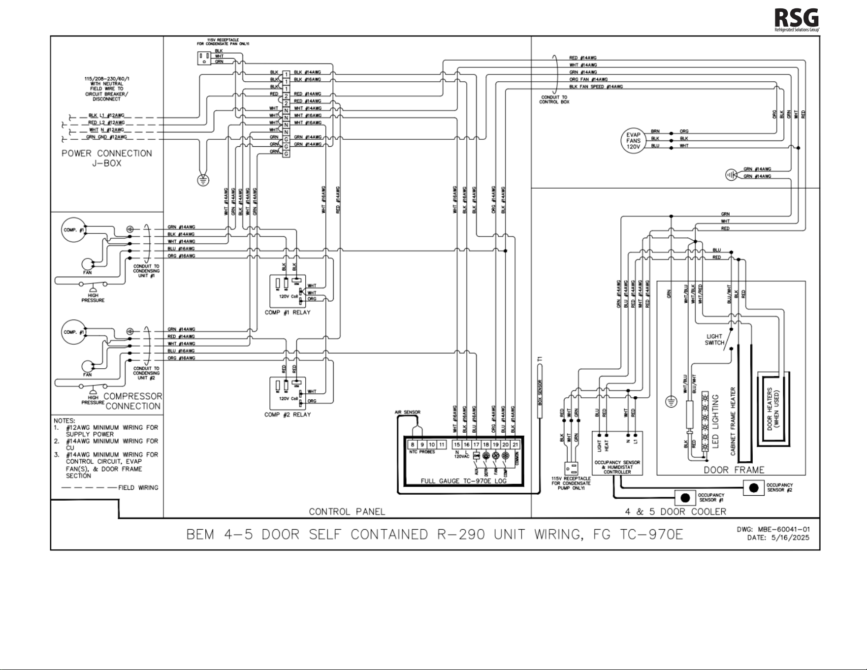
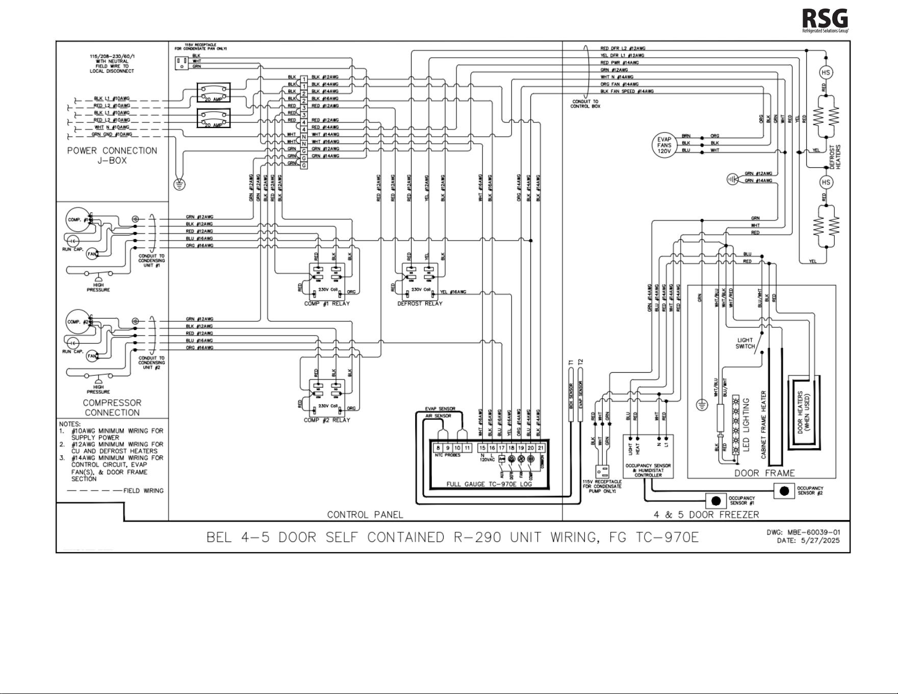
WIRING DIAGRAMS ............................................................................................................................................... 34-38
102167
- Rev. B All specifications within this publication subject to change without notice. © 2025 Master-Bilt Products, LLC. All rights reserved. 3
INTRODUCTION
Thank you for purchasing a Master-Bilt cabinet. This manual contains important instructions for installing, using and
servicing a Master-Bilt BEL/BEM-CU Bottom Coil Endless Case. A parts list is included with this manual. Read all these
documents carefully before installing or servicing your equipment.
NOTICE
Read this manual before installing your cabinet. Keep the manual and refer to it before doing any service on the
equipment. Failure to do so could result in personal injury or damage to the cabinet.
DANGER
Improper or faulty hook-up of electrical components of the refrigeration units can result in severe injury or
death.
NEVER use an extension cord to power these units. All electrical wiring hook-ups must be done in accordance
with all applicable local, regional or national standards.
NOTICE
Installation and service of the refrigeration and electrical components of the cabinet must be performed by a
refrigeration mechanic and/or a licensed electrician.
The portions of this manual covering refrigeration and electrical components contain technical instructions intended only
for persons qualified to perform refrigeration and electrical work.
This manual cannot cover every installation, use or service situation. If you need additional information, call or write us:
Customer Service Department:
Master-Bilt Products
908 Highway 15 North
New Albany, MS 38652
Phone (800) 684-8988
Fax (866) 882-7629
102167
- Rev. B All specifications within this publication subject to change without notice. © 2025 Master-Bilt Products, LLC. All rights reserved. 4
WARNING LABELS AND SAFETY INSTRUCTIONS
This symbol is the safety-alert symbol. When you see this symbol on your cabinet or in this manual, be alert to
the potential for personal injury or damage to your equipment.
Be sure you understand all safety messages and always follow recommended precautions and safe operating practices.
NOTICE TO EMPLOYERS
You must make sure that everyone who installs, uses or services your cabinet is thoroughly familiar with all
safety information and procedures.
Important safety information is presented in this section and throughout this section and throughout the manual. The
following signal words are used in the warnings and safety messages:
DANGER: Severe injury or death will occur if you ignore the message.
WARNING: Severe injury or death can occur if you ignore the message.
CAUTION:
Minor injury or damage to your cabinet can occur if you ignore the message.
NOTICE: This is important installation, operation or service information. If you ignore the message, you may damage
your cabinet.
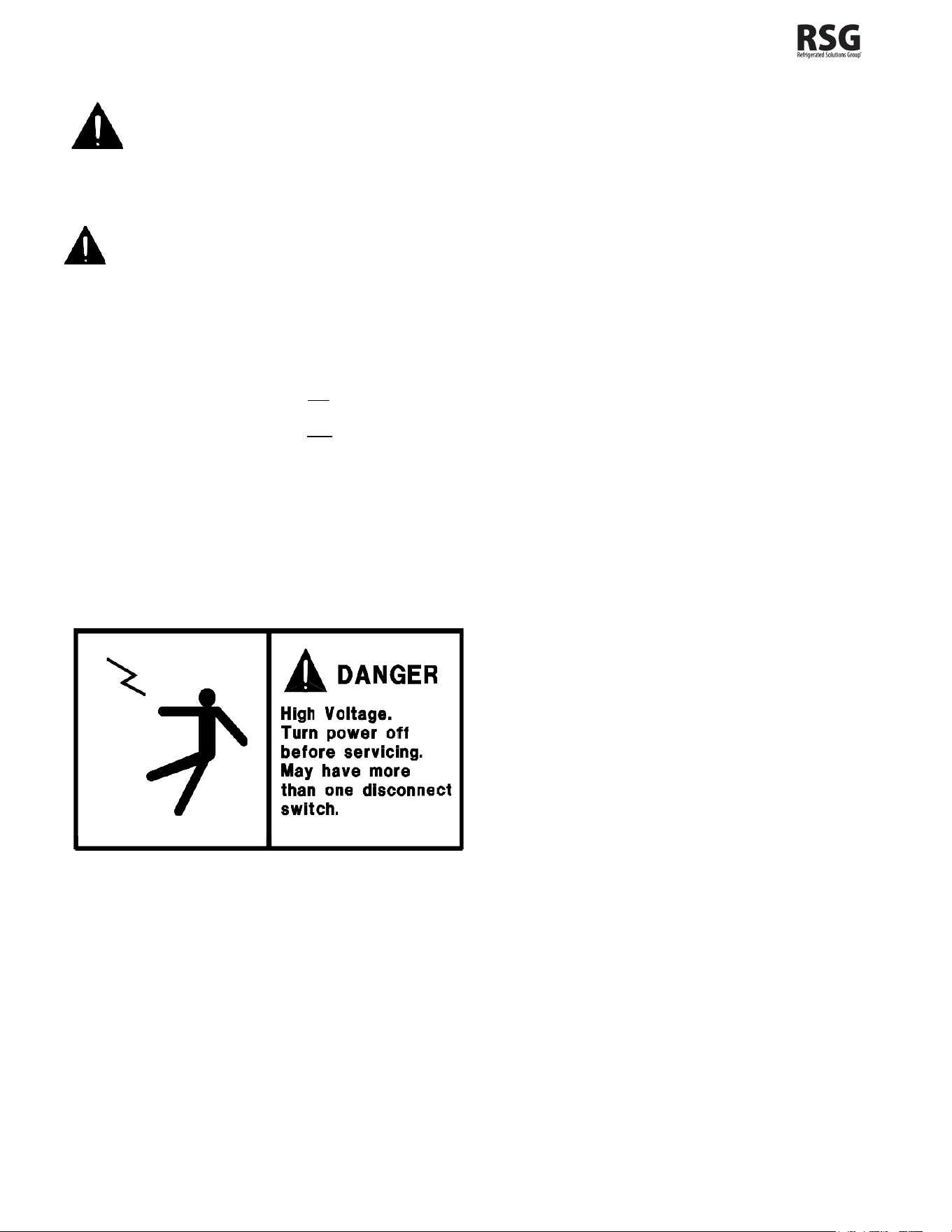
The warning and safety labels shown throughout this manual are placed on your Master-Bilt Products cabinet at
the factory. Follow all warning label instructions. If any warning or safety labels become lost or damaged, call
your customer service department at (800) 684-8988 for replacements.
This label is located on top of the electrical control
panel and on the wiring channel
102167
- Rev. B All specifications within this publication subject to change without notice. © 2025 Master-Bilt Products, LLC. All rights reserved. 5
PRE-INSTALLATION INSTRUCTIONS
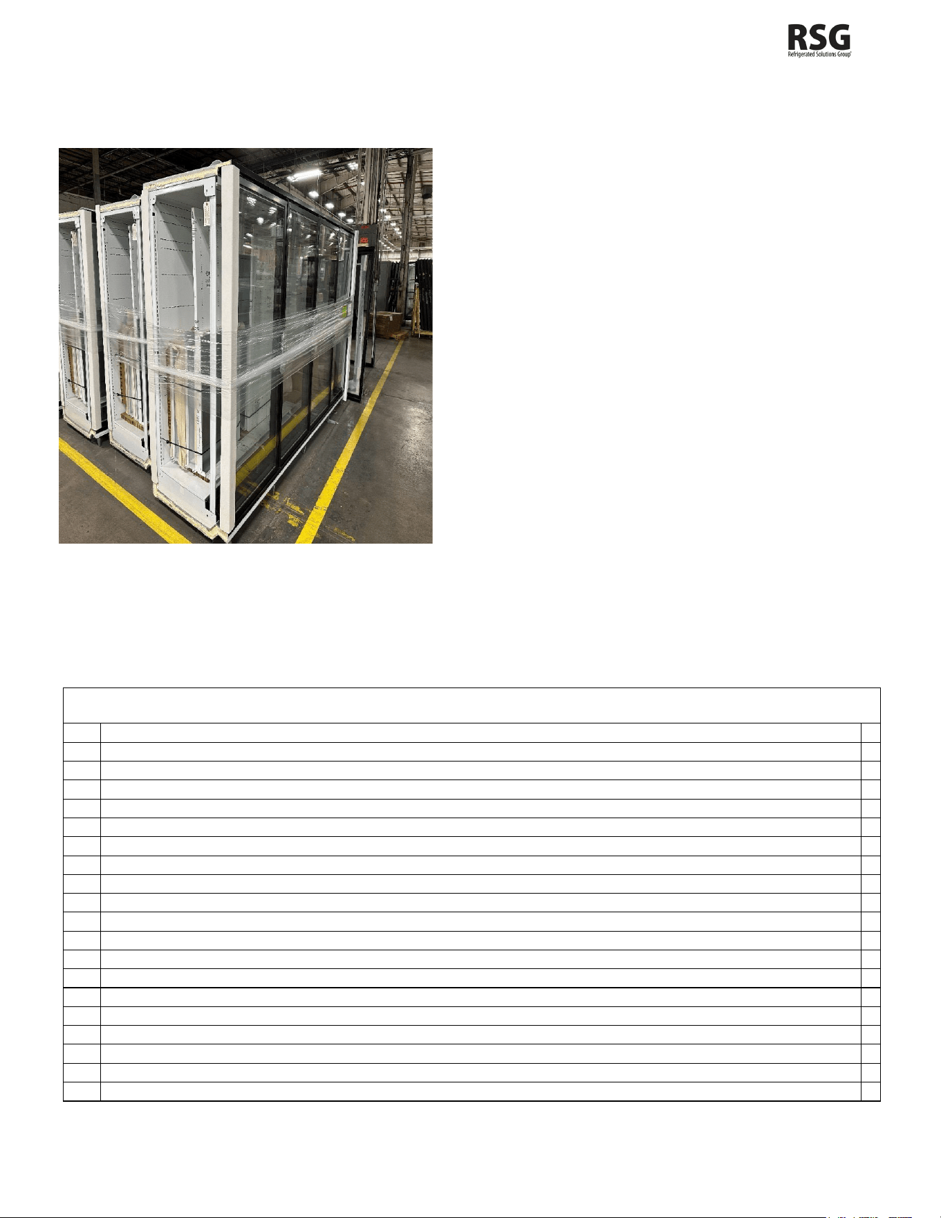
INSTRUCTIONS ON DELIVERY
Figure 1 – Initial unloading of case
PACKING LIST AND LOCATION OF ITEMS
DELIVERY, UNPACKING, AND MOVEMENT OF CASES
Once the equipment has been delivered, a forklift with a
minimum of 60” tines is required to be able to pick up the cases
without damaging them. There are hooks attached to the bottom
of all cases that allow them to be moved easily with the forklift.
All cases and equipment need to be unloaded and moved to
their desired location before unpacking or removing any of the
protective gear surrounding the cases. If removed before, there
is a chance the equipment will be damaged or scratched in the
process.
Protective gear can be found on the outer edges and corners of
the case as well as the wrapping which surrounds the center of
the case. These are only to be removed once installation is
ready, and cases are prepped to be bolted together at their final
destination.
Checklist
1)
Shims
2)
Butyl
3)
Manual Bag – Manual, Thermometer, and Hose Clamp
4)
Legs
5)
End Skirt and Brackets
6)
Assembled PVC pipe
7)
Balloon guard
8)
Pan screen
9)
Bag of screws
10)
Pump bracket
11)
Price-tag molding (6 per door)
12)
Kick-plate jointer
13)
Small and large drain tube
14)
Condensate pump
15)
Evaporator pan
16)
Solenoid – If remote system
17)
Clean out Trays (1 per door)
18)
Shroud Braces (put count in box)
19)
T-Molding and Sex Bolts
20)
Bumper and Kickplates
102167
- Rev. B All specifications within this publication subject to change without notice. © 2025 Master-Bilt Products, LLC. All rights reserved. 6
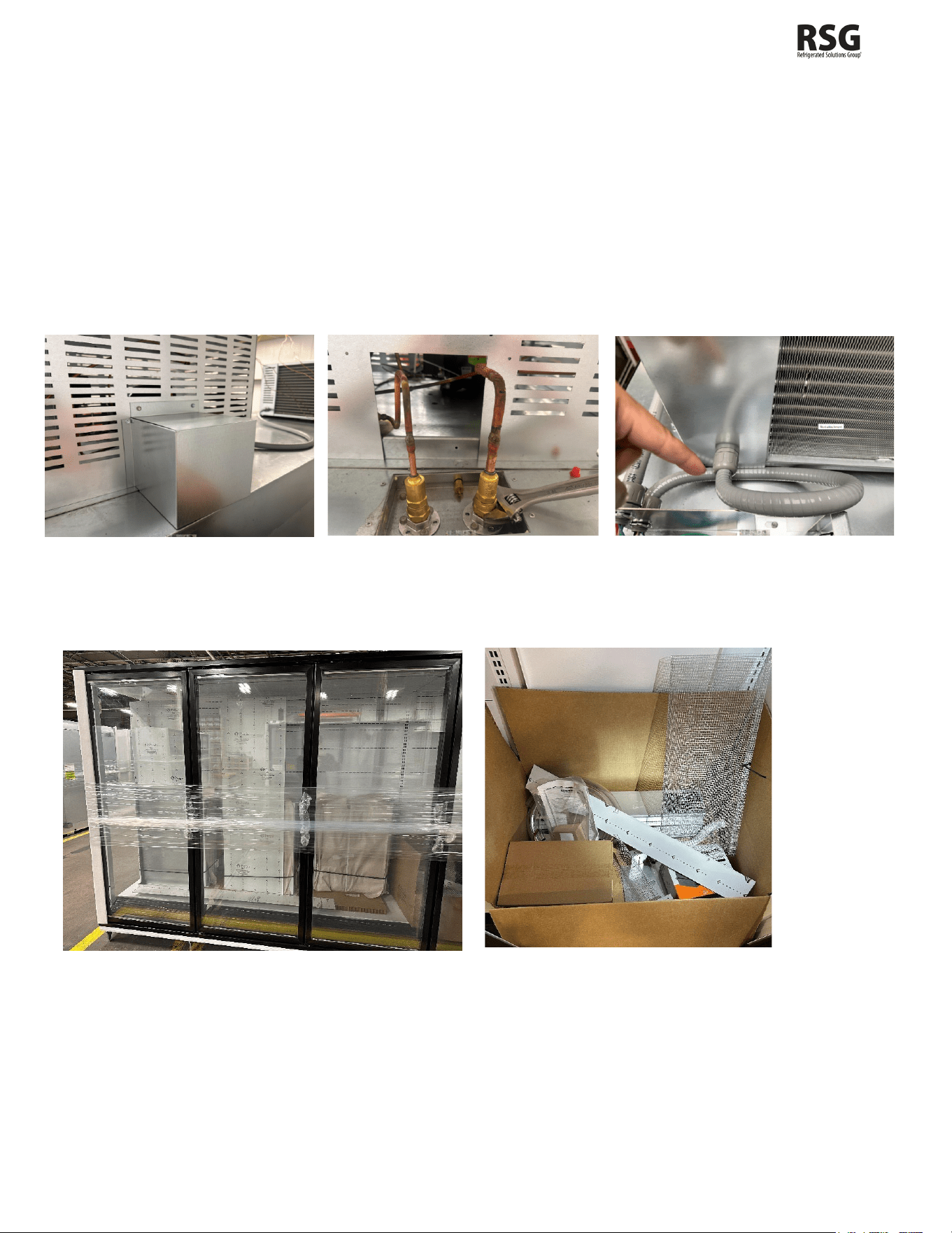
On the previous page is a general checklist for what parts can be found in the box located in the rightmost corner of the
cabinet. The number of each part varies depending on the type of model ordered. Most parts can be found in the box
shown in Figure 6. At the top of the box, you can find the end skirt in the center with the tubing to the left and the balloon
guard screen in the top right corner. Below that you can find the shroud brackets, legs, moldings, and clean out trays all
stacked on one another, as well as the evaporator pan in the bottom left corner and the condensate pump in the bottom
right.
NOTE: If the cabinet will not fit through the doorway to the cabinet final location, the Condensing Unit(s) must be removed
prior to the installation. See below figures that show quick connections and line set covers. Remove the line set cover and
disconnect the quick connects via a suitable wrench. Once the disconnection has begun, finish promptly. Then the
electrical can be disconnected. This should be done by removing the top of the condenser and disconnecting the wiring
and the seal tight. If the cabinet is equipped with a wire harness, simply unplug the condenser.
Figure 2 – Line Set Cover Figure 3 – Quick Connects Figure 4 – Line Set Cover
The other set of parts in the cabinet contain the shelf install, door install, and shroud kits. As shown in Figure 2, these
parts are stacked along the walls of the cabinet and are strapped to keep them in place during delivery.
Figure 5 – Part locations Figure 6 – Part Box
INSPECTION FOR SHIPPING DAMAGE
You are responsible for filing all freight claims with the delivering truck line. Inspect all cartons and crates for damage as
soon as they arrive. If damage is noted to shipping crates or cartons or if a shortage is found, note this on the Bill of Lading
(all copies) prior to signing.
102167
- Rev. B All specifications within this publication subject to change without notice. © 2025 Master-Bilt Products, LLC. All rights reserved. 7
If damage is discovered when the cabinet is uncrated, immediately call the delivering truck line and follow up the call with
a written report indicating concealed damage to your shipment. Ask for an immediate inspection of your concealed
damage item. Crating material must be retained to show the inspector from the truck line.
INSTALLATION INSTRUCTIONS
GENERAL INSTRUCTIONS
1. Be sure the equipment is properly installed by competent service people.
2. Keep the equipment clean and sanitary so it will meet your local sanitation codes. Wipe up all spills, clean with
water and a mild detergent, then rinse with clean water.
3. Rotate your stock so that older stock does not accumulate. This is especially important for ice cream. A "First-
In, First-Out" rotation practice will keep the products in good sellable condition. Do not place product in a BEL
when it is soft or partially thawed. Also, the product should not be put in the case for at least 6 hours after it is
started.
4. Stock cases as quickly as possible, exposing only small quantities to store temperatures for short periods of
time.
5. When replacing burned fluorescent bulb/LED light bar, be sure that the electrical power to the lighting circuit is
turned off.
To comply with N.S.F. requirements, this cabinet must be sealed to the floor with NSF listed silicone
sealant. Before moving the cabinet into place, route cabinet plumbing with P-trap to store drain line or
install optional condensate pan.
6. Disconnect shall be installed by the installer in the field
STORE CONDITIONS
The Master-Bilt BEL/BEM-CU cases are designed to operate in the controlled environment of an air-conditioned store.
The store temperature should be at or below 75°F and a relative humidity of 55% or less. At higher temperature or humidity
conditions, the performance of these cases may be affected and the capacity diminished. It is not uncommon in a newly
constructed store for the temperature and humidity to be above design conditions. These excessive conditions may
produce sweating in the case until the store is operational, and the ambient environment is more desirable.
LOCATION
The Master-Bilt BEL/BEM-CU should not be positioned where it is directly exposed to rays of the sun or near a direct
source of radiant heat or air flow.
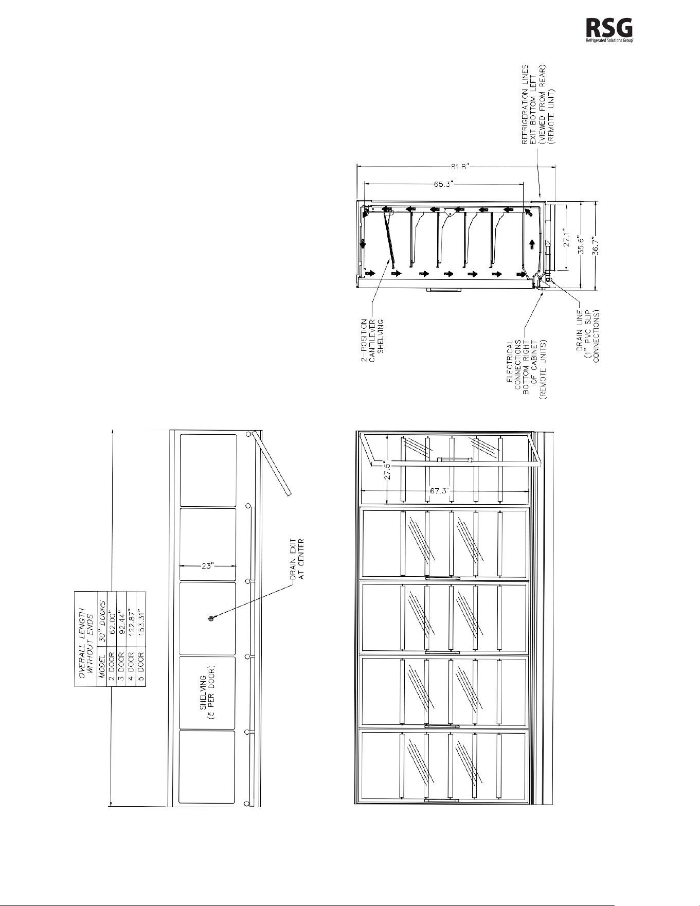
Cabinet should not be built into an enclosed area. If this case is to be located against a wall there should be at least a 4”
space between the wall and the back of the case, with 4” open space at top and 1” on both ends. This space will allow for
the circulation of air behind the case which will prevent condensation on the exterior surfaces.
102167
- Rev. B All specifications within this publication subject to change without notice. © 2025 Master-Bilt Products, LLC. All rights reserved. 8
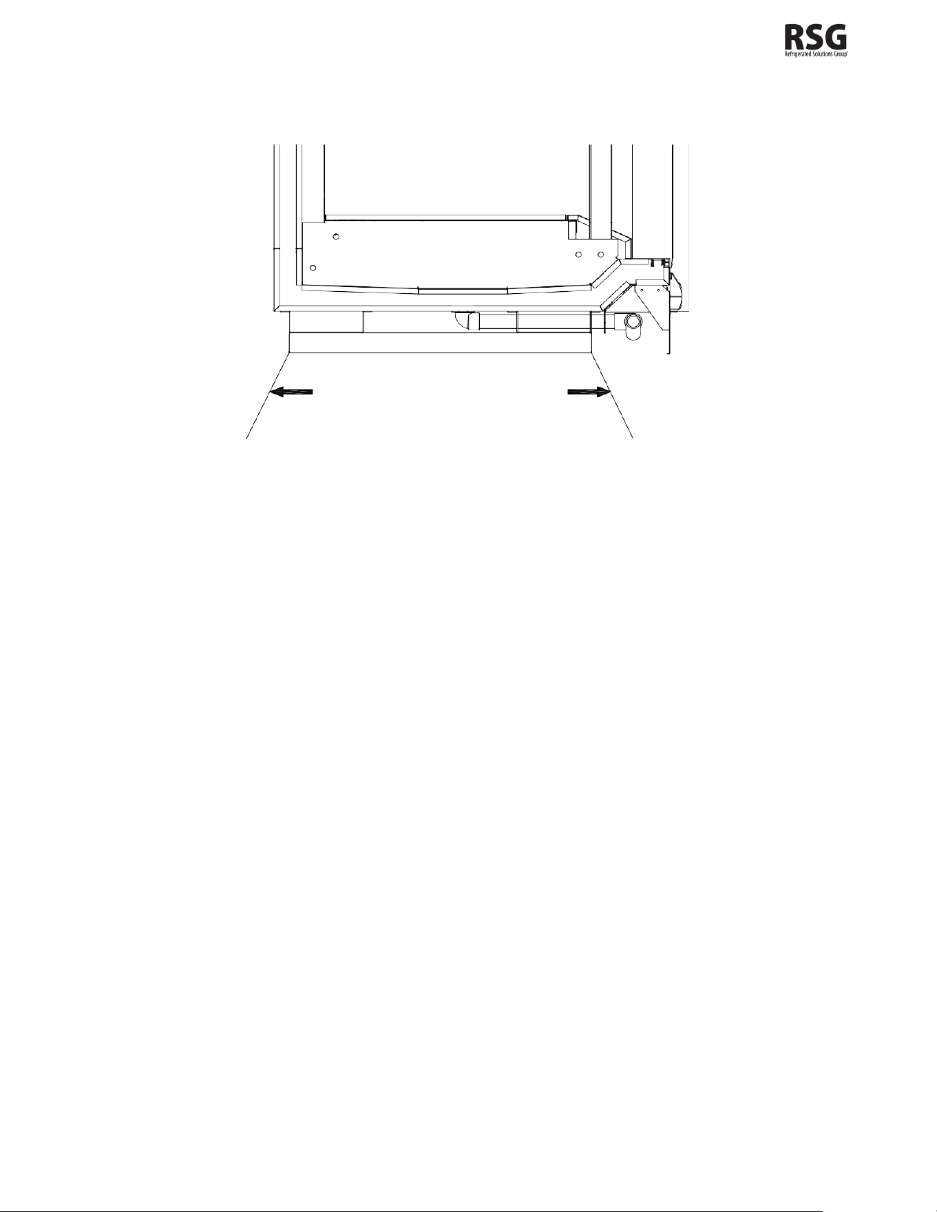
Make sure that the floor that will support this equipment is of adequate strength to prohibit sagging. After confirming the
dimensions of the case with the blueprint measure off and mark on the floor the exact location of the cases for the entire
lineup. Snap chalk lines where the base skids of the case are to be located as shown in Figure 7.
Figure 7 – Chalk lines at front and back edges of skids
102167
- Rev. B All specifications within this publication subject to change without notice. © 2025 Master-Bilt Products, LLC. All rights reserved. 9
102167
- Rev. B All specifications within this publication subject to change without notice. © 2025 Master-Bilt Products, LLC. All rights reserved. 10
LEVELING
It is very important that this equipment be perfectly level. This will allow for proper and complete drainage of the evaporator
coil and for proper case alignment. A perfectly level area is generally not available where the equipment is to be installed.
Mark the location of all case joining points front and back. Use a transit to locate the highest point on the chalk lines. This
point will be a reference point for determining shim-pack heights. Using the reference point, mark the difference directly
on the floor to each joining point front and back. Shim each joining point to equal the reference point as required. Tape
all shims in place. If the installation is an entire lineup install the case that will be positioned at the highest point first. Check
that the equipment in the lineup is level as the installation proceeds.
JOINING MULTIPLE SECTIONS
Remove the case from its shipping skid. Set the first case into its desired position with required shims in preparation for
joining it with its adjacent case.
Cases joined together require an application of butyl caulking
to provide an air-tight seal. Apply a generous bead to all
exposed foam edges at the end of the case. Inspect the bead
to make sure there are no gaps and that there is sufficient
material to provide a complete seal. The cases are now ready
to be joined together. Cases are not able to be pulled
together with the bolts. Remove the second case from its
shipping skid and move it into position against the end of the
first case. Properly level the second case with the appropriate
shims.
Bolt the cases together through the five holes that are provided
in the end frame as shown in Figure 8. Tighten the bolts until
all seams are fully closed. Do not overtighten.
Figure 8 – Case joining detail
Bolt the included sex bolts through the door frame to secure the door
frames together as shown in Figure 9. Make sure that the gasket strips
on each frame are intact and free of damage to ensure a proper seal
between the two frame sections. Place a small bead of butyl behind the
gasket strips to obtain a more solid seal. Repeat the above process for
all other cases in the lineup.
Figure 9 – Door frame joining detail
102167
- Rev. B All specifications within this publication subject to change without notice. © 2025 Master-Bilt Products, LLC. All rights reserved. 11
DOOR ADJUSTMENT
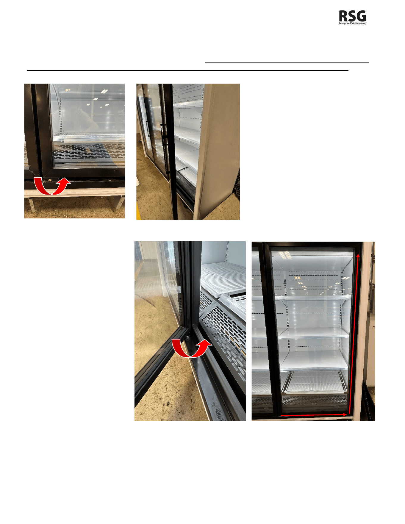
For adjustment needed when doors are unleveled or seem to be sagging (sawtooth doors), there are adjustors or screws
that can be turned to tune the doors to their desired position. Be sure to use a level to make sure the door is flush
with the rest of the unit and is perpendicular to the floor it’s sitting on before making any adjustments.
The adjuster on the front of the door shown
in Figure 10 should be turned
counterclockwise to increase the tension
when opening or shutting the door.
You should test this by slightly opening the
door and seeing if it shuts on its own or not.
If the door does not shut, then you need to
increase the tension. If you need to release
tension, turn the adjuster clockwise.
Figure 10 – Front adjuster Figure- 11 Open door test
The adjuster located on the
inside of the door shown in
Figure 11 can be turned
clockwise or
counterclockwise to fix the
sawtooth effect that can be
seen between sagging doors.
Turning the adjuster
counterclockwise, pulls the
door toward the operator and
raises the opposite corner.
Turning it clockwise does the
opposite – it pushes the door
away from the operator and
lowers the opposite corner.
Figure 12 – interior adjuster Figure 13 – Door adjustments
102167
- Rev. B All specifications within this publication subject to change without notice. © 2025 Master-Bilt Products, LLC. All rights reserved. 12
PLUMBING
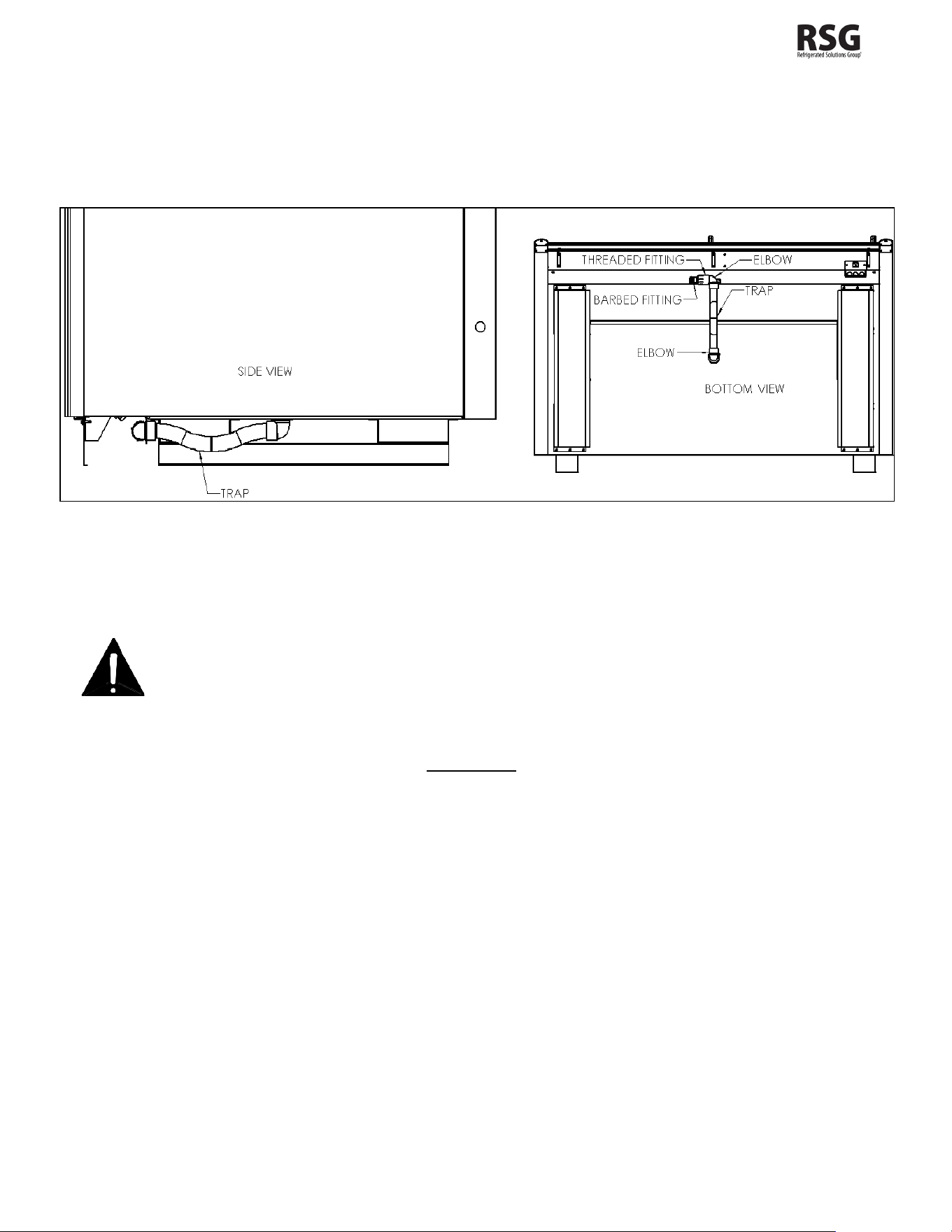
The BEL/BEM-CU is equipped with a condensate drain kit to be installed. The drain kit connects to the bottom middle of
the cabinet. This drain kit includes a (2) 90 Elbows, a Threaded Fitting, a Barbed Fitting, and a Trap. Connect the supplied
flexible hose to the barbed fitting and to the drain or condensate pump, whichever is applicable. It is very important that
this trap be installed as it will result in diminished performance of the case without it. The kickplate will need to be removed
to see the piping.
Figure 14 – Drain detail
1. Always install drains in accordance with local codes.
2. Use the largest possible size pipe for drains, one inch minimum is recommended.
3. Provide as much downhill slope as possible.
4. Prevent drains from freezing. Do not install drains in contact with uninsulated suction lines.
NOTICE TO STORE OWNERS / MANAGERS
Moisture or liquid around or under the cabinet is a potential slip/fall hazard for persons walking by or working in
the general area of the cabinet. Any cabinet malfunction or housekeeping problem that creates a slip/fall hazard
around or under the cabinet should be corrected immediately.
If moisture or liquid is observed around or under a Master-Bilt cabinet, an immediate investigation should be made by
qualified personnel to determine the source of the moisture or liquid. The investigation should determine if the cabinet is
malfunctioning or if there is a drainpipe leaking.
102167
- Rev. B All specifications within this publication subject to change without notice. © 2025 Master-Bilt Products, LLC. All rights reserved. 13
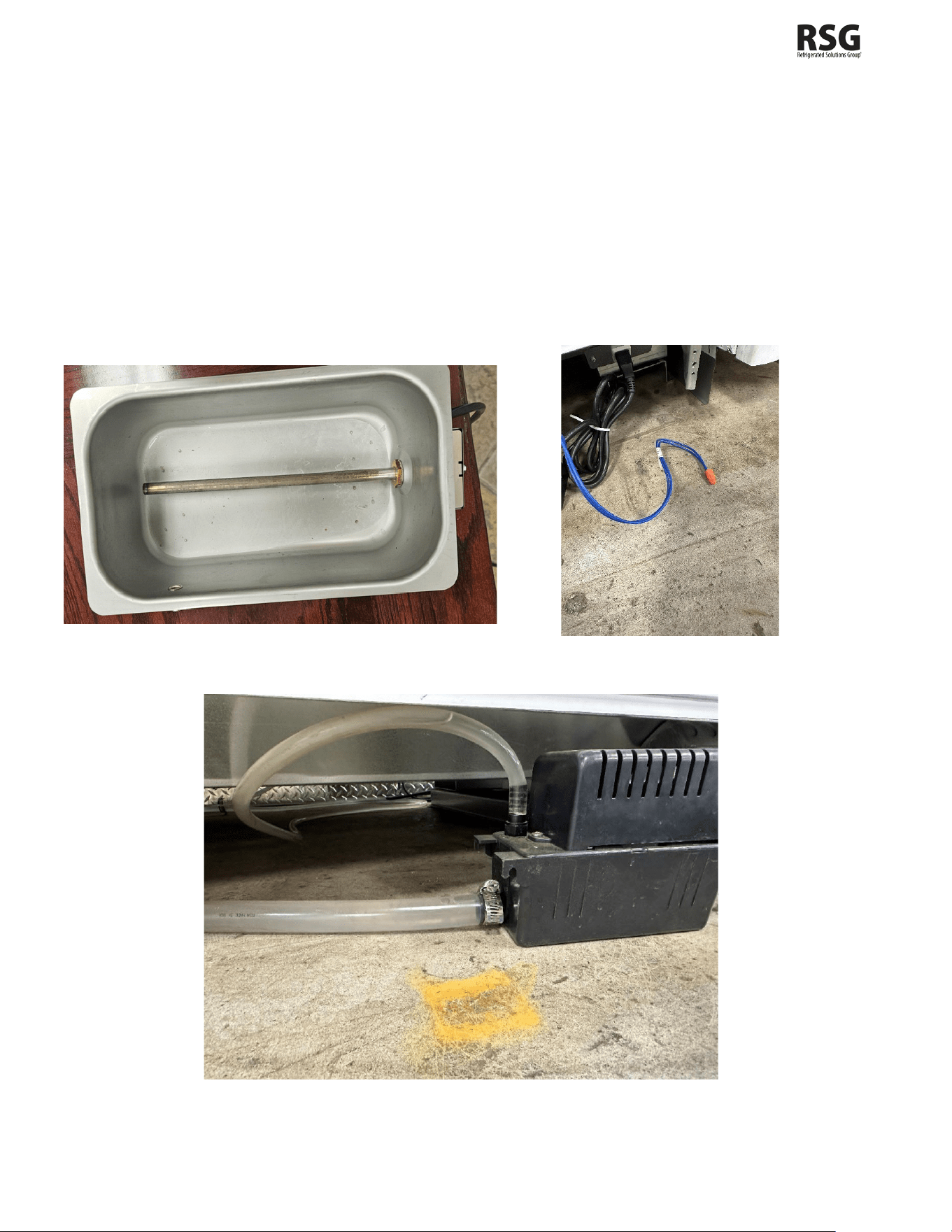
Condensate pump and pan
The collection pan as shown in Figure 15 should be installed at the top of the unit with plastic tubing leading down to the
pump below. The tubing should terminate in the pan and raise the float switch to turn on the heater, which will evaporate
the water.
Another set of tubing can be attached to the side port of the condensate pump with a metal pipe fitting. This tubing
should be led to a drain or discharge point where the excess water is able to be let out to avoid water pooling on top of
the cabinet.
The blue wires from the pump housing are an auxiliary contact that is not used in this application. You need to cap the
end of these wires together as they are in Figure 16 below.
Figure 15 – Collection pan Figure 16 – Safety switch
Figure 17 – Condensate pump
102167
- Rev. B All specifications within this publication subject to change without notice. © 2025 Master-Bilt Products, LLC. All rights reserved. 14
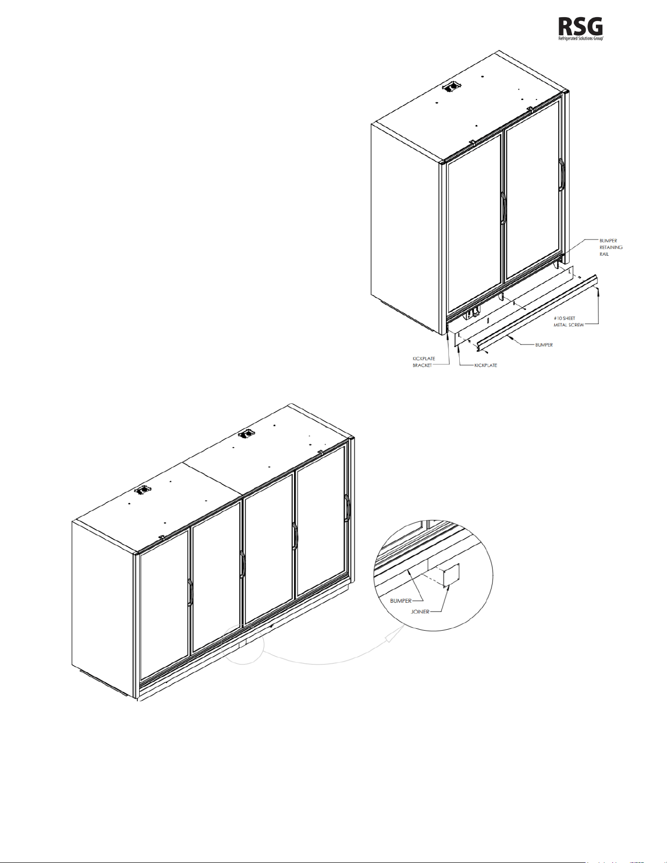
INSTALLING THE KICKPLATE
Install the kickplate behind the bumper and in front of the
kickplate bracket. Secure the kickplate first by attaching it
to the top pre-drilled holes of the kickplate brackets using
the supplied #10x3/4” sheet metal screws. Then install the
bumper by placing the top in the retaining rail and placing
sheet metal screws through the bottom pre-drilled holes
of the bracket. Refer to Figure 18 for the placement of the
kickplate.
INSTALLING JOINING TRIM
To install the kickplate joiner, first make sure that the
bumper is removed. Attach the kickplate retainer with the
(2) #10x3/4” self-drilling sheet metal screws provided with
the kit as shown in Figure 19. Reattach the bumper onto
the bumper retaining rail and attach with screws as shown
in Figure 15. (Joiner is only for cabinets that have a
partition in between them)
Figure 18 –Kickplate installation
Figure 19 – Kickplate joiner details
102167
- Rev. B All specifications within this publication subject to change without notice. © 2025 Master-Bilt Products, LLC. All rights reserved. 15
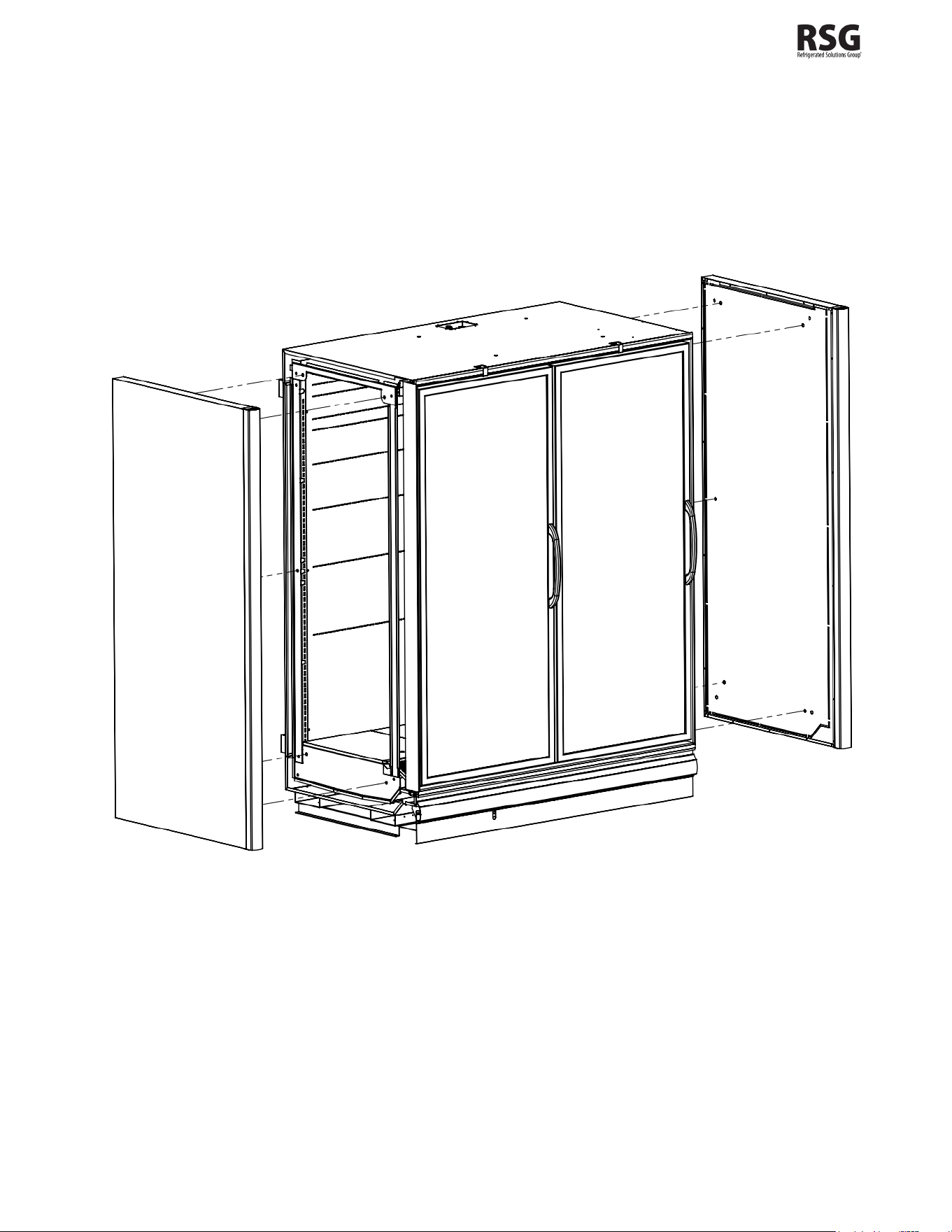
REMOVING AND REPLACING THE ENDS
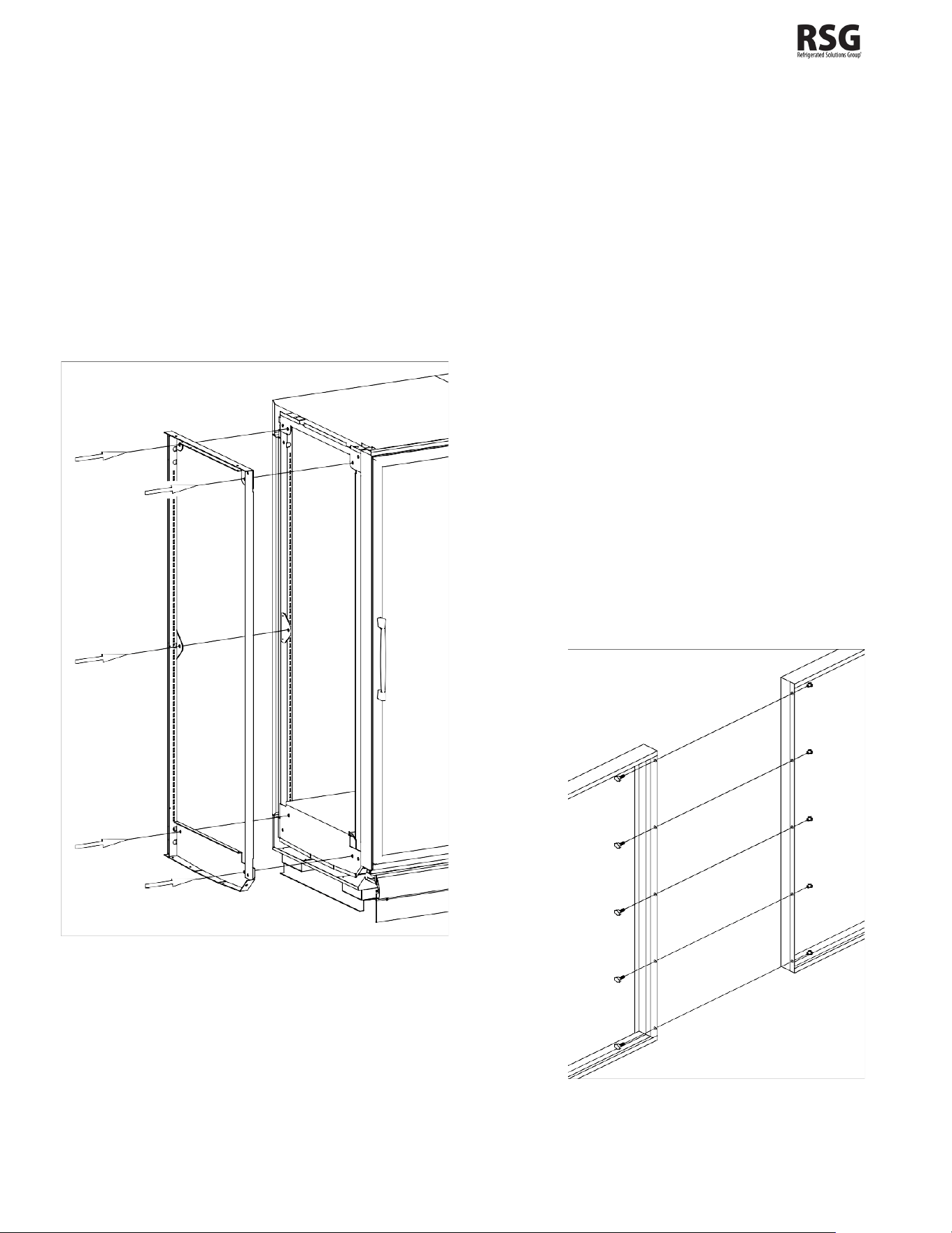
The ends of a BEL/BEM-CU are bolted to the ends of the cabinet itself. There are five attachment points on each end as
shown in Figure 20. Each attachment point uses a 5/16” hex head bolt and washer. The bolts are fed through the holes
in the end frames and into threaded retainers in the end panel. Care should be taken not to overtighten the bolts as this
could lead to the stripping of the threaded retainer. Consult the factory to see if it is necessary to remove or replace the
end of a BEL/BEM-CU.
Figure 20 – End panel detail
102167
- Rev. B All specifications within this publication subject to change without notice. © 2025 Master-Bilt Products, LLC. All rights reserved. 16
INSTALLING SHROUDS
Shrouds are installed on top of the cabinet on the front and side panels. Install the front shroud first. Do this by taking the
front shroud and placing the bottom flange facing outward toward the cabinet doors as shown in Figure 22. Bolt the
shroud into the front panel and continue to install the angle brackets. Angle brackets are to be mounted on the top flange
of the shroud and then bolted on to the top of the cabinet. Make sure that the shroud is level or perpendicular to the
cabinet after each installation.
Install the side shrouds by positioning them in line with the front shroud and bolting them together. For the side shrouds,
the bottom flange should be on the inside as shown in Figure 21. Once they are attached to the front shroud, you can
then bolt the shrouds into the cabinet and attach the angle brackets as done before on the front.
Figure 22 – Front shroud
Figure 21 – Full Shroud from above
Figure 23 – Side shroud
102167
- Rev. B All specifications within this publication subject to change without notice. © 2025 Master-Bilt Products, LLC. All rights reserved. 17
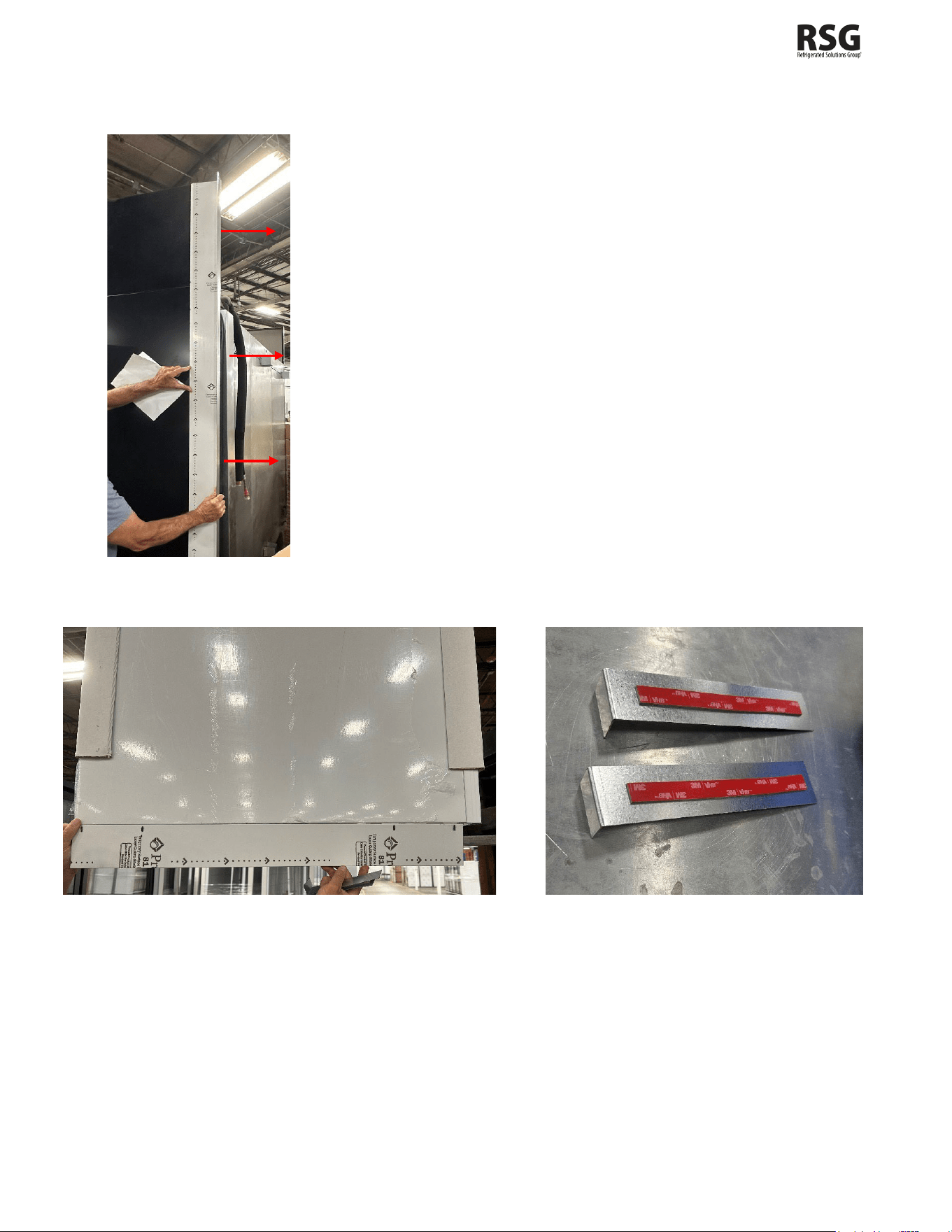
INSTALLING REAR CLOSEOFF AND ENDSKIRTS
The rear close-off panel should be installed after the ends and
shrouds have been put on. The wide piece of the panel should
be placed flush against the side of the cabinet and then bolted
into the cabinet itself as well as into the shrouds above. Once
the panel is mounted, push the cabinet back unit the panel hits
the wall. Mount the thin part of the panel into the wall and bolt
it until it no longer moves. Doing this will provide the cabinet
with enough space in the back to be able to circulate air in and
out of the system.
The end skirts should be installed with the brackets seen in
Figure 26. The brackets should be placed under the cabinet
with the flange pointing towards the side of the fridge. To
install the brackets, peel the double-sided tape located on the
top and line up the flange with one of the corresponding holes
on the end skirt as shown in Figure 25. Once the bracket is
securely fastened and lined up correctly, bolt the end skirt to
the hanging flange.
Figure 24- Rear Close-Off
Figure 25 – End Skirt Figure 26 – End Skirt Brackets
102167
- Rev. B All specifications within this publication subject to change without notice. © 2025 Master-Bilt Products, LLC. All rights reserved. 18
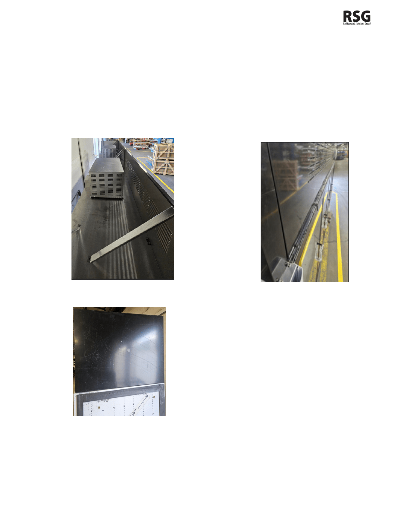
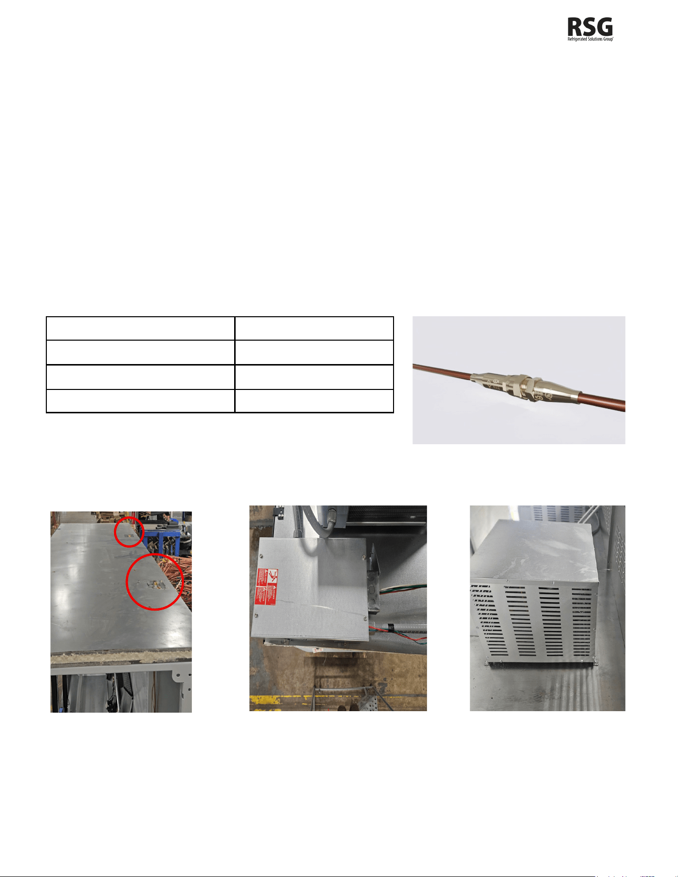
INSTALLING CONDENSING UNIT AND WIRING
The blank squares you see in Figure 27 are the general locations for where all the equipment should go. The boxes
respectively from nearest to farthest house the control box, the evaporator pan, and the condensing unit. Be sure to
install the condenser(s) in the same place that the were disconnected from if they were removed to enter the building.
The control box should be moved to its correct spot on top of the cabinet as shown in Figure 28. Once everything is in
place, connect the control box to the condensing in the same fashion it was removed in. Then take the quick connect
hookups and fasten them to the condensing unit. Refer to Table 1 to see what torque value should be used depending
on the size of the quick connect.
The balloon guard is installed last on the rear side of the condensing unit. As shown in Figure 29, mount the balloon
guard on the rear coil and angle the wire so that if an object were to be sucked in it would be blocked and there
would still be a constant flow.
When disconnecting the quick connects, ensure the system has been shut off for a minimum of 10 minutes.
Table 1: Craft Quick Connect Torque Specs
Size
Torque value (N.m)
1/4
25-30
3/8
25-30
1/2
25-30
Figure 27 – Top View of Cabinet Figure 28 – Control Box Figure 29 – Condensing unit
102167
- Rev. B All specifications within this publication subject to change without notice. © 2025 Master-Bilt Products, LLC. All rights reserved. 19
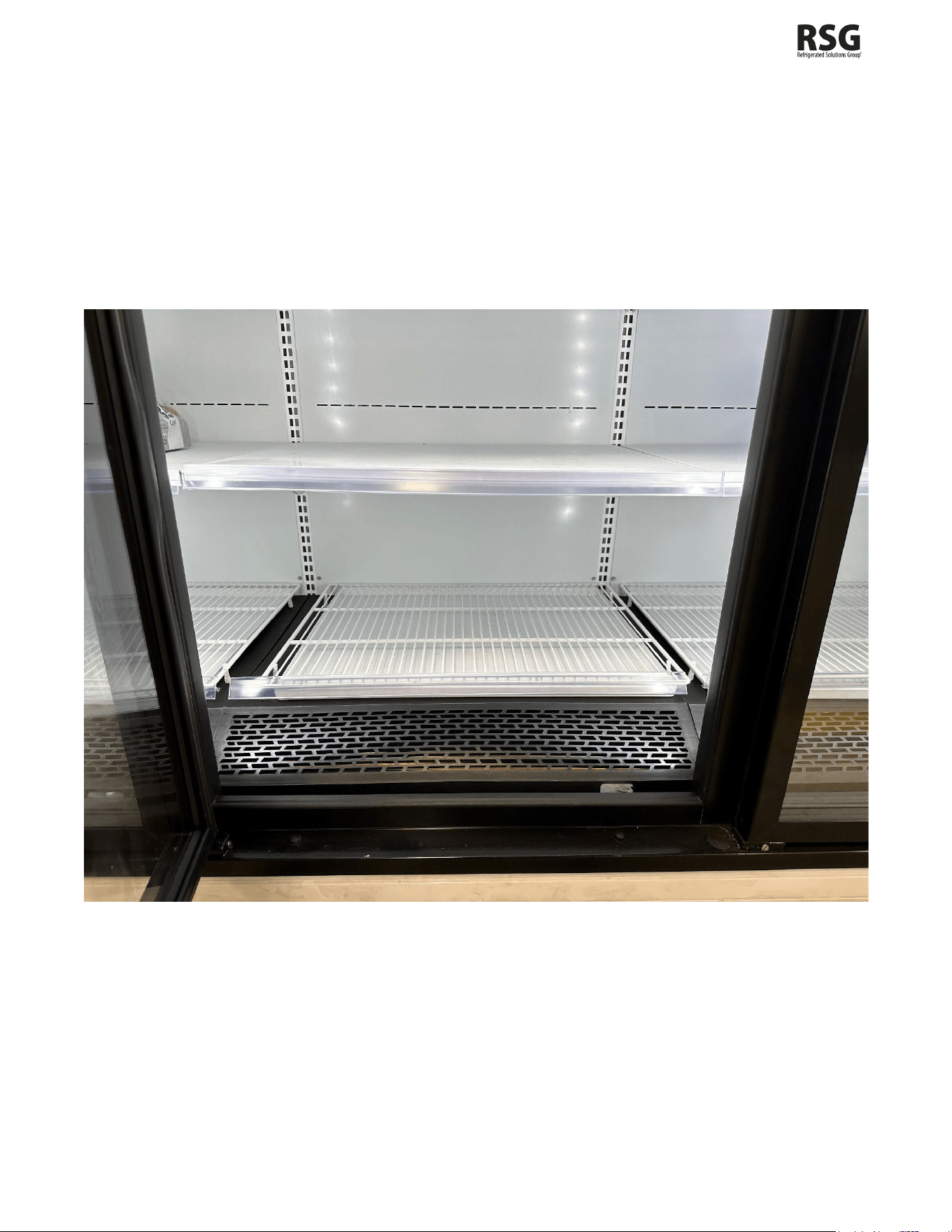
INSTALLING SHELVES, CLEANOUT PAN, AND WIRE BOTTOM SHELF
Open the cabinet door as much as possible before attempting to install shelving. Once the cabinet door is open to its
fullest extent, take the given shelves and slide each one back until they reach the back wall. Position your shelves to
their desired location and use the hooks on the back to slide the shelf into its designated track. After the hooks are
placed into the track, push down gently on the shelf to lock it into place.
The cleanout pan and wire bottom shelf should be placed directly under the bottom shelf at the bottom of the cabinet.
First install the cleanout pan and then insert the wire bottom shelf right above it. Line up both in accordance with the
shelving above.
Figure 30 – Cabinet Shelving

102167
- Rev. B All specifications within this publication subject to change without notice. © 2025 Master-Bilt Products, LLC. All rights reserved. 20
ELECTRICAL WARNING
Before servicing electrical components in the case or the doors or door frames make sure all power to case is off.
Always use a qualified technician.
It is very important that full voltage and overcurrent protection requirements for condensing units, defrost heaters, fans,
door and frame heaters, etc. be provided at installation. Wire sizing must be adequate to maintain full voltage under
amperage loads specified in the charts in this manual.
REFRIGERANT PIPING
There is no need for Technician’s field piping on these systems. They are self-contained R290 systems that have been
charged at the factory and completely tested before leaving.
REFRIGERATION SYSTEM EVACUATING AND CHARGING
In the event of an issue in the field that requires a technician (technician must have EPA 608 certification) to open the
refrigeration circuit, the technician must refer to the Technician’s Considerations section in this manual on page #29 and
follow the traditional instructions below:
1. Blow out all refrigerant lines with dry nitrogen or carbon dioxide to eliminate the possibility of dirt, scale, etc.
remaining inside.
2. Connect all lines and leak test all connections.
3. Connect a good high vacuum pump to both the low and high side evacuation valves.
4. Operate the pump until a vacuum of 1500 microns (0.06 inches of mercury) absolute pressure is obtained. At this
point, the vacuum should be broken by the introduction of refrigerant into the system, through a drier, until the pressure
is brought up to zero pounds gauge. Repeat this procedure two more times. During the final evacuation, a vacuum
of 500 microns (0.02 inches of mercury) absolute pressure should be obtained. After this vacuum is reached, the
system can be fully charged with refrigerant.
102167
- Rev. B All specifications within this publication subject to change without notice. © 2025 Master-Bilt Products, LLC. All rights reserved. 21
MASTER-BILT ELECTRONIC REFRIGERATION CONTROL OPERATION
102167
- Rev. B All specifications within this publication subject to change without notice. © 2025 Master-Bilt Products, LLC. All rights reserved. 22
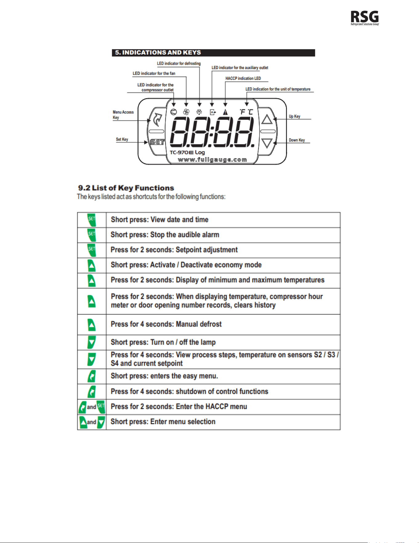
OPERATION
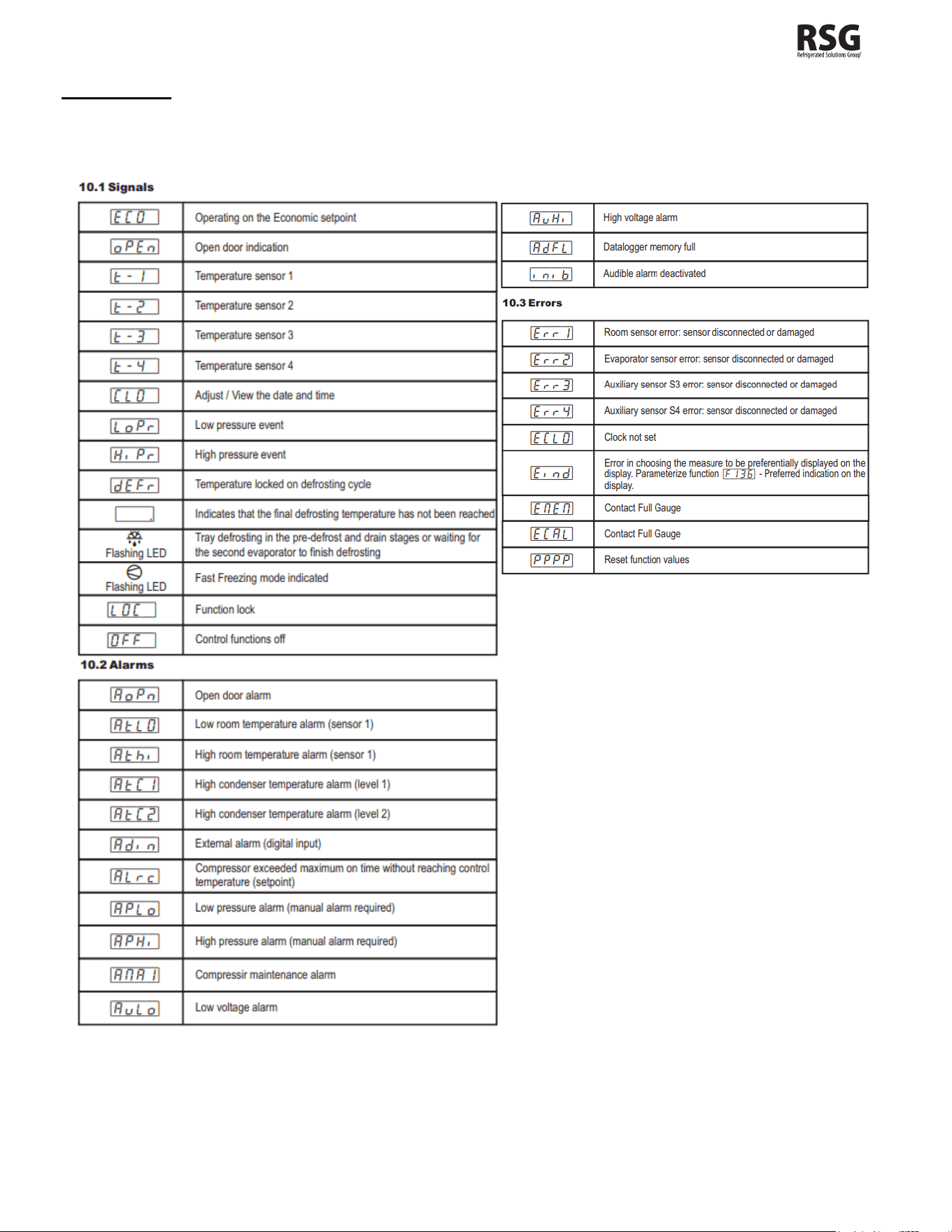
DISPLAY
During normal operation, the display shows the measured temperature. In addition, any of the following symbols may be
displayed:

102167
- Rev. B All specifications within this publication subject to change without notice. © 2025 Master-Bilt Products, LLC. All rights reserved. 23
ADDITIONAL INFO
How to See the Setpoint
• Press and immediately release the SET key: the display will show the setpoint value.
• Press and immediately release the SET key or wait for 5 seconds to display the probe value again.
Setting the set point (desired temperature)
• press SET for more than 2 seconds. then the set value will be displayed, and the message “SP” will appear,
followed by the value for adjusting the normal setpoint.
• Using the UP or DOWN keys to modify the value
• press SET to confirm the new value then wait 10 seconds
Manual Defrost
• Within the dEFr option or by pressing the UP key for 4 seconds or using the external key connected to the digital
input. Activation or deactivation is indicated by the message dEFr ON or dEFr OFF respectively.
Continuous Cycle
• When a defrost is not in progress, it can be activated by pressing and holding the UP button for about 3 seconds.
The compressor operates to maintain the CCS setpoint for the time set through the CCt parameter. The cycle
can be terminated before the end of the set time using the same activation button (UP button for 3 seconds).
How to Change a Parameter Value
• Enter the Programming mode by press and immediately releasing the SET + DOWN buttons.
• Using the UP and DOWN keys go to the CodE option and short press.
• Using the UP and DOWN keys enter the code “123” and confirm using the SET key. This will allow the user to
change the parameter values.
• Within the main menu, select the option “Func” and select the desired function using the UP or DOWN keys.
• Select the function using the SET key and then use the UP or DOWN key to set the desired value.
To exit: Long Press the SET key until the “- - - -“ appears.
How to Assign a MODBUS Address
• Follow steps 1-5 of “How to Change a parameter Value” to access the function menu.
• Using the UP or DOWN key scroll to function (F 142)
• Press SET to select.
• Choose the address number using the UP or DOWN buttons and press SET again to save.
To exit: Long Press the SET key until the “- - - -“ appears.
Note: that devices cannot have duplicate addresses on the network. Assigning MODBUS addresses prior to
terminating the network and leaving the address of device 1 as unused until the network is connected can prevent
duplicate addressing network issues.
How to Lock/Unlock the Keyboard
To lock the keyboard:
• Access the option LOC within the easy menu using the MENU ACCESS KEY and then confirm using the SET key.
• The message “no” will be displayed if the lock is disabled.
• Press and hold the DOWN key for the time configured for this function (F 140).
• Activation will be indicated by the message “LOC On” and will only occur if the function (F 139) is set to 1 or 2.
To unlock the keyboard:

102167
- Rev. B All specifications within this publication subject to change without notice. © 2025 Master-Bilt Products, LLC. All rights reserved. 24
• Turn off the controller and turn it on again with the DOWN key pressed.
• Keep the key pressed until the message “LOC OFF” indicates that it has been unlocked (10 seconds)
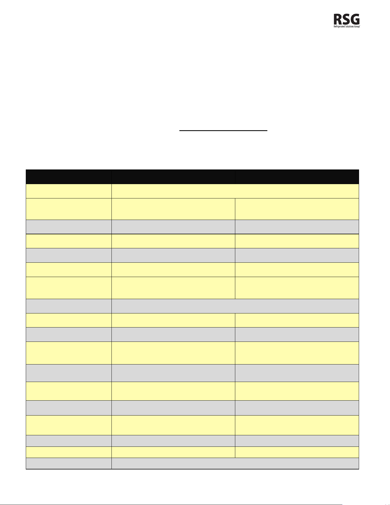
LIST OF PARAMETERS
Here is a list of the parameters the value of which can be changed in the programming mode, as well as their ranges.
Display
Symbol
Parameters
Range
Factory
Setting
Factory
Setting
BEM
BEL
F01 Setpoint Temperature
-15°F - 40°F
-
- 2°F
F01 Setpoint Temperature
32°F - 50°F
35°F
-
F17 Delay time when powering up the controller
2
2
F20 Interval between defrost (cooling)
720
360
F21 Interval between defrost (heating)
720
720
F28 Number of Defrost per Day
4
4
F42 Drain Time
0
2
F97 Low ambient temperature alarm (S1)
-58°F - 221°F
25°F
-20°F
F98 High ambient temperature alarm (S1)
-58°F - 221°F
120°F
110°F
F142 Address of the instrument on the RS-485
Network
1-247
1
1
*This is a standard setting; climates with extreme humidity may require more defrost times or longer fail-safe settings.
*for any other parameters and setting please consult factory for more details and instructions
Note: The other parameters not listed here are set up with default values. If you need details or instructions on these
other parameters and settings, consult the TC-970E controller manual.

102167
- Rev. B All specifications within this publication subject to change without notice. © 2025 Master-Bilt Products, LLC. All rights reserved. 25
Installation
• The TC-970E controller should be mounted on a vertical panel, in a 29 mm x71 mm hole, and secured using the
special bracket supplied.
• The temperature range allowed for correct operation is 0 to 60°C.
• Avoid places subject to strong vibrations, corrosive gases, excessive dirt, or humidity. The same
recommendations apply to probes.
• Allow air to circulate through the cooling holes.
• The device is provided with screw terminal block to connect cables with a cross section up to 2.5 mm
2
.
• Before connecting cables verify that the power supply complies with the device’s requirements.
• Separate the probe cables from the power supply cables, from the outputs and the power connections.
• Do not exceed the maximum current allowed on each relay, in case of heavier loads use a suitable
external relay.
NOTE: Most controllers are already installed, this is only if your unit does not have a controller, or it has
to be replaced.
Probe Connection
• The probes should be mounted with the bulb upwards to prevent damage due to casual liquid infiltration.
• It is recommended the thermostat probe be placed away from air streams to measure the average room
temperature correctly.
• Place the defrost termination probe among the evaporator fans in the coldest place, (where most ice is formed)
and far from heaters or from the warmest place during defrost to prevent premature defrost termination.
STARTING PROCEDURE
1. Check the temperature holding range against the control setting.
2. Check the defrost control system to see that all ice is removed from the coil during each defrost cycle.
3. Ensure Defrost terminates and System starts cooling again.
4. Reinstall pipe coverings for condensing units after installation if condensers are removed.
Installation and operating instructions are provided with each model and indicate a clearance of open at the top, 3 in.
at the rear and 0 in. at each side.

102167
- Rev. B All specifications within this publication subject to change without notice. © 2025 Master-Bilt Products, LLC. All rights reserved. 26
FINAL CHECKLIST
A. Check high-low pressure control settings.
B. Check operating pressure.
C. Check electrical requirements of units to supply voltage.
D. Check the setting of the thermostatic expansion valve for proper operation. Approx. 10
°F superheat.
E. Check sight glass for proper refrigerant charge.
F. Check condensing unit for vibrating or rubbing tubing. Dampen and clamp as required.
G. All valves should be completely open counterclockwise.
H. Check the packing nuts on all service valves.
I. Replace all service valve caps and latch unit covers.
J. Check the refrigeration line for proper P-traps and proper locations.
K. Check the drain for proper P-traps and proper locations.

102167
- Rev. B All specifications within this publication subject to change without notice. © 2025 Master-Bilt Products, LLC. All rights reserved. 27
DOOR PLASTIC (GASKET RETAINER) REPLACEMENT
Starting in corner, gently pull the rubber gasket away from the door plastic. With gasket removed, insert a flat-head
screwdriver under the outside edge of the plastic, and gently pry up. At either end of the plastic run the screwdriver the
complete length and width of the door rail. With the outside edge of the plastic released, push the plastic towards the glass
to remove. To replace, insert the edge of the plastic into the inside door rail groove. Snap the outside edge of the plastic
cover over the outside edge of the door rail.
DOOR GASKET REPLACEMENT
Remove the old gasket by starting in the corner, gently pulling gasket away from the plastic. To replace the gasket, remove
the top and bottom door plastic, and slide the gasket up the two verticals. Slide the top and bottom plastic onto the gasket
and replace the top and bottom plastic on the door rail. Tuck in the corners of the gasket with a flat-head screwdriver.
LED DRIVER REPLACEMENT, BEL/BEM-CU
For a BEL/BEM-CU, the LED Drivers are located inside the door mullions and can be accessed from the front of the door
frame. Remove the door that hinges on the mullion where the ballast will be replaced. From the front of frame, remove
contact plate & retainer by inserting a flat-head screwdriver under back edge of black contact plate retainer, and gently pull
to unsnap retainer from the mullion. Repeat for the other side and remove the contact plate. With the ballast now exposed,
remove the screw on the top end of the ballast. Loosen the screw on the bottom of the driver.
Disconnect all lead wires by separating the connectors. If cut, leave enough lead wire to re-connect the new driver with a
wire nut. Insert the bottom of the new ballast in the punched tabs and re-install the top screw in the top end of the driver.
Tighten both screws. Re-connect new driver’s lead wires following the wiring diagrams provided.
DOOR HEATER REPLACEMENT
Remove door gasket and plastic. Remove the center side access plate located on the side of the door. The wiring for the
door is done in the center side of the hinge rail. To remove the heater, unplug the solid lead wires: Black or Red, White,
and Green/Yellow (ground). If the glass is heated, unplug the Black and White solid wires from the glass. Heater wire lies
in the track on the back outside edge of door. Pull the heater out. Reverse instructions to replace the door heater. Plug
in Black or Red lead wire from hinge pin to Black or Red lead wire from heater, White lead wire from hinge pin to White
heater lead, and Green/Yellow lead from hinge pin to ground.
Note: If glass is heated, plug in Black and White lead wires coming off heater loom to Black and White lead wires from
glass. Replace side access plate. Replace the door plastic and gasket.
NOTICE
The doors on these cabinets are Anti-Fog Glass so it is important to follow the information below when cleaning
these doors. Failure to observe the details below in cleaning doors will void door supplier warranty.
• Do not use sealants, gaskets, or other materials containing silicone that can contaminate the coating.
• Do not use tape, glue, stickers, attachments, or magic markers on the anti-fog coating.
• Do not use razor blades or any other mechanical device to remove foreign residue or objects directly from the
coated glass.
• Do not use abrasive cleaners or materials on the coated glass. Examples of these cleaners or materials include
Ajax, Brillo, Comet, Scotch Brite, Steel Wool, and Soft Scrub.
• Do not use cleaners or materials on the coated glass that hinder the anti-fog performance by leaving residue or
damaging the surface. Examples of these cleaners include: Armor All, Tilex, Bleach, Windex no-drip, Windex
Wipes, Pledge, or any product containing silicone oils or waxes.
• Recommended cleaners include: Isopropyl Alcohol, Greased Lighting, Formula 409 Grease & Grime, Formula 409
Grease & Surface, Fantastic, Windex Vinegar, Windex Original, Now, Mean Green, or Mr. Clean (degreasing
cleaners).
• Recommended cleaning is with a soft dry or slightly damp towel, or with one of the degreasing cleaners listed
above.

102167
- Rev. B All specifications within this publication subject to change without notice. © 2025 Master-Bilt Products, LLC. All rights reserved. 28
SERVICE INSTRUCTIONS (Trouble Shooting Guide)
1. High head pressure and high back pressure:
A. Condenser coil clogged or restricted.
B. Condenser fan motor defective.
2. Low back pressure and low head pressure:
A. Restriction in system.
B. Refrigerant undercharged.
C. Leak in system.
3. Pressures normal – cabinet warm:
A. Coil blocked with frost or ice (see #4).
B. Refrigerant undercharged.
C. Control set too warm.
D. Air screen disturbance.
4. Coil blocked with frost or ice:
A. Defective temperature control. E. P-trap in drain not installed.
B. Time clock is not operating properly. F. Doors aren’t sealing when closed.
C. Improper time clock setting. G. Air screen disturbance.
D. Ambient conditions above 75°F/55% RH. H. Evaporator fan motor defective.
E. Defrost heater is not operating. I. Low voltage.
5. Compressor starts and runs – but cycles on overload:
A. Low voltage.
B. Overload protector defective.
C. High head pressure (see#1).
6. Compressor will not start – hums, but cycles on overload:
A. Low voltage.
B. Relay defective.
C. Overload is defective.
D. High head pressure (see #1).
7. Special service situations:
If moisture or liquid is observed around or under a Master-Bilt cabinet, an immediate investigation should be made by qualified
personnel to determine the source of moisture or liquid. The investigation made should determine if the cabinet is
malfunctioning or if there is a simple housekeeping problem.
Moisture or liquid around or under a cabinet is a potential slip/fall hazard for persons walking by or working in the general area
of the cabinet. Any cabinet malfunction or housekeeping problem that creates a slip/fall hazard around or under a cabinet should
be corrected immediately.

102167
- Rev. B All specifications within this publication subject to change without notice. © 2025 Master-Bilt Products, LLC. All rights reserved. 29
TECHNICIAN’S CONSIDERATIONS:
Technicians should have an EPA 608 certification type 1 to work on this cabinet.
Technicians should exercise caution when disconnecting quick connects or opening refrigerant circuits.
Technicians should use ventilation fans anytime a refrigeration circuit is opened.
Technicians should survey the area for ignition sources before opening a refrigeration circuit.
Technicians should correct all nearby electrical faults and discharge all capacitors before opening a refrigeration
circuit.
Technicians should avoid working in confined spaces with A3 refrigerants. Ventilation should be used if
necessary.
Technicians should check the area for flammable refrigerants with an approved leak detector to find present
refrigerant before starting work. This leak detection equipment should not be arcing or sparking. It should be
intrinsically safe.
Technicians should have a fire extinguisher present during service and installation. A dry chemical or CO
2
fire
extinguisher should be adjacent to the charging area.
No person carrying out work in relation to a REFRIGERATING SYSTEM which involves exposing any pipe work
shall use any sources of ignition in such a manner that it may lead to the risk of fire or explosion. All possible
ignition sources, including cigarette smoking, should be kept sufficiently far away from the site of installation,
repairing, removing and disposal, during which refrigerant can possibly be released to the surrounding space.
Prior to work taking place, the area around the equipment shall be surveyed to make sure that there are no
flammable hazards or ignition risks. "No Smoking" signs shall be displayed.
Technicians should ensure that the area is in the open or that it is adequately ventilated before breaking into the
system or conducting any hot work. A degree of ventilation shall continue during the period that the work is
carried out. The ventilation should safely disperse any released refrigerant and preferably expel it externally into
the atmosphere.
Where electrical components are being charged, they shall be fit for the purpose and to the correct specification.
At all times, the manufacturer's maintenance and service guidelines shall be followed. If in doubt, consult the
manufacturer's technical department for assistance.
The following checks shall be applied to installations using FLAMMABLE REFRIGERANTS:
a)
The actual REFRIGERANT CHARGE is in accordance with the room size within which the refrigerant-
containing parts are installed.
b)
The ventilation machinery and outlets are operating adequately and are not obstructed.
c)
If an indirect refrigerating circuit is being used, the secondary circuit shall be checked for the presence
of refrigerant.
d)
Marking to the equipment continues to be visible and legible. Markings and signs that are illegible
shall be corrected.
e)
Refrigerating pipes or components are installed in a position where they are unlikely to be exposed
to any substance which may corrode refrigerant containing purpose and to the correct specification.
At all times, the manufacturer's maintenance and service guidelines shall be followed. If in doubt,
consult the manufacturer's technical department for assistance.
The following checks shall be applied to installations using FLAMMABLE REFRIGERANTS:
a)
The actual REFRIGERANT CHARGE is in accordance with the room size within which the refrigerant
containing parts are installed;

102167
- Rev. B All specifications within this publication subject to change without notice. © 2025 Master-Bilt Products, LLC. All rights reserved. 30
b)
The ventilation machinery and outlets are operating adequately and are not obstructed;
c)
If an indirect refrigerating circuit is being used, the secondary circuit shall be checked for the presence
of refrigerant;
d)
Marking to the equipment continues to be visible and legible. Markings and signs that are illegible shall
be corrected;
e)
Refrigerating pipe or components are installed in a position where they are unlikely to be exposed to
any substance which may corrode refrigerant containing
Checks to electrical devices
Repair and maintenance to electrical components shall include initial safety checks
and component inspection procedures. If a fault exists that could compromise safety, then no electrical supply
shall be connected to the circuit until it is satisfactorily dealt with. If the fault cannot be corrected immediately but
it is necessary to continue operation, an adequate temporary solution shall be used. This shall be reported to
the owner of the equipment, so all parties are advised.
Initial safety checks shall include:
a) The capacitors are discharged: this shall be done in a safe manner to avoid possibility of sparking.
b)
That no live electrical components and wiring are exposed while charging, recovering or purging
the system.
c)
That there is continuity of earth bonding.
During repairs, Technicians should, to sealed components, all electrical supplies shall be disconnected from the
equipment being worked upon prior to any removal of sealed covers, etc. If it is absolutely necessary to have an
electrical supply to equipment during service, then a permanently operating form of leak detection shall be
located at the most critical point
Technicians should check that cabling will not be subject to wear, corrosion, excessive pressure, vibration, sharp
edges, or any other adverse environmental effects. The check shall also take into account the effects of aging
or continual vibration from sources such as compressors or fans
Under no circumstances shall potential sources of ignition be used in the searching for or detection of refrigerant
leaks. A halide torch (or any other detector using a naked flame) shall not be used.
The following leak detection methods are deemed acceptable for all refrigerant systems. Electronic leak
detectors may be used to detect refrigerant leaks but, in the case of
FLAMMABLE REFRIGERANTS, the sensitivity might not be adequate or might need recalibration. (Detection
equipment shall be calibrated in a refrigerant-free area.) Ensure that the detector is not a potential source of
ignition and is suitable for the refrigerant used. Leak detection equipment shall be set at a percentage of the LFL
of the refrigerant and shall be calibrated to the refrigerant employed, and the appropriate percentage of gas (25
% maximum) is confirmed.
102167
- Rev. B All specifications within this publication subject to change without notice. © 2025 Master-Bilt Products, LLC. All rights reserved. 31
Leak detection fluids are also suitable for use with most refrigerants but the use of detergents containing chlorine
shall be avoided as the chlorine can react with the refrigerant and corrode the copper pipework.
NOTE Examples of leak detection fluids are
- Bubble method,
- Fluorescent method agents.
If a leak is suspected, all naked flames shall be removed/extinguished.
If a leakage of refrigerant is found which requires brazing, all the refrigerant shall be recovered from the system.
Removal of refrigerant shall be according to Clause 101.DVS.9 in UL60335-2-89.
MASTER-BILT PART NUMBERS
The table below gives Master-Bilt part numbers for use when ordering replacement parts for your BEL/BEM-CU cases.
Description
BEL (Low Temp)
BEM (Med Temp)
Evaporator Coil
Consult Factory
Defrost Heater
17-09629 BEL2/4
103130 BEL3/5
N/A
Electronic Control
231228
231228
Box Sensor
231229
231229
Evaporator Sensor
231230
231230
Evaporator Fan Motor
158919
158919
Standard Shelf
Solid Shelf
231258 231258
Door Frame
Consult Factory
Standard Door (Black)
100972
100972
LED Driver
LED Mullion light bar
173668
173668
Lamp Left Side light bar
173667
173667
Lamp Right Side light
bar
173672
173672
Door Gasket
37-01385 (30”)
37-01386 (24”)
37-01385 (30”)
37-01386 (24”)
Torque-Master (Black)
000105
000105
Torque Rod
35-01840
35-01840
Top Hinge Pin
35-01842
35-01842
Door Frame Heaters
Consult Factory

102167
- Rev. B All specifications within this publication subject to change without notice. © 2025 Master-Bilt Products, LLC. All rights reserved. 32
SALE AND DISPOSAL
OWNER RESPONSIBILITY
If you sell or give away your Master-Bilt cabinet, you must make sure that all safety labels and the Installation - Service
Manual are included with it. If you need replacement labels or manuals, Master-Bilt will provide them free. Contact the
customer service department at Master-Bilt at (800) 684-8988.
The customer service department at Master-Bilt should be contacted at the time of sale or disposal of your cabinet so
records may be kept of its new location.
If you sell or give away your Master-Bilt cabinet and you evacuate the refrigerant charge before shipment, Master-Bilt
recommends that the refrigerant charge be properly recovered in compliance with section 608 of the Clean Air Act effective
November 1995 and in accordance with all applicable local, regional, or national standards.
Decommissioning:
Before carrying out this procedure, it is essential that the technician is completely familiar with the equipment
and all its detail: It is recommended good practice that all refrigerants are recovered safely. Prior to the task being
carried out, an oil and refrigerant sample shall be taken in case analysis is required prior to re-use of recovered
refrigerant. It is essential that electrical power is available before the task commences.
a)
Become familiar with the equipment and its operation.
b)
Isolate the system electrically.
c)
Before attempting the procedure, ensure that:
i)
Mechanical handling equipment is available, if required, for handling refrigerant
cylinders.
ii)
All personal protective equipment is available and being used correctly.
iii)
The recovery process is supervised at all times by a competent person.
iv)
Recovery equipment and cylinders conform to the appropriate standards.
d)
Pump down refrigerant system, if possible.
e)
If a vacuum is not possible, make a manifold so that refrigerant can be removed from various parts of the
system.
f)
Make sure that cylinder is situated on the scales before recovery takes place.
g)
Start the recovery machine and operate in accordance with instructions.
h)
Do not overfill cylinders (no more than 80 % volume liquid charge).
i)
Do not exceed the maximum working pressure of the cylinder, even temporarily.
j)
When the cylinders have been filled correctly and the process completed, make sure that the cylinders and
the equipment are removed from site promptly and all isolation valves on the equipment are closed off.
k)
Recovered refrigerant shall not be charged into another REFRIGERATING SYSTEM
unless it has been cleaned and checked.

102167
- Rev. B All specifications within this publication subject to change without notice. © 2025 Master-Bilt Products, LLC. All rights reserved. 33
Labelling
Equipment shall be labelled stating that it has been de-commissioned and emptied of refrigerant. The label shall
be dated and signed. For appliances containing FLAMMABLE REFRIGERANTS, ensure that there are labels
on the equipment stating the equipment contains FLAMMABLE REFRIGERANT.
Recovery
When removing refrigerant from a system, either for servicing or decommissioning, it is recommended good
practice that all refrigerants are removed safely.
When transferring refrigerant into cylinders, ensure that only appropriate refrigerant recovery cylinders are
employed. Ensure that the correct number of cylinders for holding the total system charge is available.
All
cylinders to be used are designated for the recovered refrigerant and labelled for that refrigerant (i.e., special
cylinders for the recovery of refrigerant). Cylinders shall be complete with pressure-relief valve and associated
shut-off valves in good working order. Empty recovery cylinders are evacuated and, if possible, cooled before
recovery occurs.
The recovery equipment shall be in good working order with a set of instructions concerning the equipment that
is at hand and shall be suitable for the recovery of all appropriate refrigerants including, when applicable,
FLAMMABLE REFRIGERANTS. In addition, a set of calibrated weighing scales shall be available and in good
working order. Hoses shall be complete with leak-free disconnect couplings and in good condition.
Before using the recovery machine, check that it is in satisfactory working order, has been properly maintained
and that any associated electrical components are sealed to prevent ignition in the event of a refrigerant release.
Consult manufacturer if in doubt.
The recovered refrigerant shall be returned to the refrigerant supplier in the
correct recovery cylinder, and the relevant waste transfer note arranged. Do not mix refrigerants in recovery units
and especially not in cylinders.
If compressors or compressor oils are to be removed, ensure that they have been
evacuated to an acceptable level to make certain that FLAMMABLE REFRIGERANT does not remain within the
lubricant. The evacuation process shall be carried out prior to returning the compressor to the suppliers. Only
electric heating to the compressor body shall be employed to accelerate this process. When oil is drained from
a system, it shall be carried out safe
102167- Rev. B All specifications within this publication subject to change without notice. © 2025 Master-Bilt Products, LLC. All rights reserved. 34
102167- Rev. B All specifications within this publication subject to change without notice. © 2025 Master-Bilt Products, LLC. All rights reserved. 35
102167- Rev. B All specifications within this publication subject to change without notice. © 2025 Master-Bilt Products, LLC. All rights reserved. 36
102167- Rev. B All specifications within this publication subject to change without notice. © 2025 Master-Bilt Products, LLC. All rights reserved. 37
102167- Rev. B All specifications within this publication subject to change without notice. © 2025 Master-Bilt Products, LLC. All rights reserved. 38

102167- Rev. B All specifications within this publication subject to change without notice. © 2025 Master-Bilt Products, LLC. All rights reserved. 39

102167- Rev. B All specifications within this publication subject to change without notice. © 2025 Master-Bilt Products, LLC. All rights reserved. 40
Master-Bilt
908 Highway 15 North
New Albany, MS 38652
800-647-1284 Sales
800-684-8988 Parts/Service

