Instruction Manual
ELECTRIC AIR COMPRESSOR
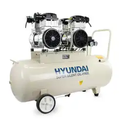
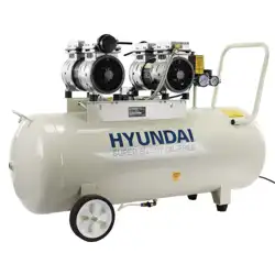
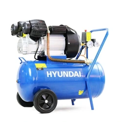
HY3050V, HY30100V
WARNING: Read the instructions carefully before use. Iss:Nov/24

2
CONTENTS
PAGE NO.S
1
SAFETY
3 - 7
2
MACHINE SPECIFIC SAFETY
7 - 8
3 ASSEMBLY 10
4 PREPERATION 11
5 STARTING PROCEDURE 12
6 STOPPING PROCEDURE 13
7 USING THE MACHINE 13
8 MAINTENANCE
13-14
9 TROUBLESHOOTING 15
10 SPECIFICATION 16
11 RECYCLING AND PRODUCT DISPOSAL 17
12 DECLARATION OF CONFORMITY
18
INDEX
13 CONTACT DETAILS 19
FEATURES 9
3
1.1 General Safety Notes.
1.2 The operator of the machine is responsible for, and has a duty of care in making sure
that the machine is operated safely and in accordance with the instructions in this user
manual. Keep the manual safe and pass it on if the machine is loaned or sold to another
user.
1.3 Please note the following safety points.
1.4 The machine should never be left it in a condition which would allow an untrained or
unauthorised person/s to operate this machine.
1.5 All due care and diligence should be taken by the operator for the safety of and with
regard to those around whilst using the machine.
1.6 Some or all of the following - warning signs, symbols and/or PPE pictograms may ap-
pear throughout this manual. You MUST adhere to their warnings. Failure to do so
may result in personal injury to yourself or those around you.
DANGER
Indicates a hazard, which, if not avoided, could result in serious injury or death.
WARNING
Indicates a hazard, which, if not avoided, could result in serious injury.
CAUTION
Indicates a hazard which, if not avoided, might result in minor or moderate injury.
NOTE
Indicates a situation that could easily result in equipment damage.
READ and keep the manual safe and pass it on if the machine is loaned or sold to another user.
You MUST fully understand all instructions to ensure you use and operate the machine safely.
Appropriate Personal Protective Equipment (PPE), MUST be worn at all times when operating or
repairing the machine.
1. SAFETY

1.40
1.41
1.42
1.43
1.44
1.45
Electrical Safety (where applicable).
Electricity can kill – NEVER work on LIVE/ENERGISED equipment.
Prior to carrying out
any maintenance work you MUST identify electrical isolation
methods and isolate all electrical supplies.
Prior to use and with all electrical supplies isolated, you MUST check all electrical
cables, plugs and connectors for the following;
Are intact and have no signs of damage, to include but not limited to bare wires,
chaffing, cuts and loose wiring.
If there are any signs of damage, the damaged item MUST be taken out of
service until the damage has been repaired by an electrically competent person.
1.60
1.61
1.62
1.63
1.64
1.65
Vibrations (where applicable).
Prolonged use of hand held (operated) machines will cause the user to feel the
effects of/from vibrations. These vibrations can lead to white finger (Raynaud’s
phenomenon) or carpal tunnel syndrome. This condition reduces the ability of the
hand to feel and regulate temperature, causing numbness and heat sensations and
may cause never damage and circulatory tissue death.
Not all factors that lead to white finger disease are known, but cold weather,
smoking and other diseases that affect blood vessels and blood circulation as well
as large and long-lasting impact of shocks are considered factors in the formation of
white finger. Note the following to reduce the risk of white finger and carpal tunnel
syndrome;
Wear gloves and keep your hands warm.
Take regular breaks.
All of the above precautions may help reduce the risk of white finger disease but not
rule out the carpal tunnel syndrome. Long-term and regular users are therefore

7
recommended to observe the condition of your hands and fingers. Seek medical
attention immediately if any of the above symptoms should occur.
1.70 Noise (where applicable).
1.71 The operating noise of the machine can damage your hearing. Wear hearing
protection such as earplugs or ear defenders to protect your hearing. Long-term
and regular users are advised to have hearing checked regularly. Be especially
vigilant and cautious when hearing ear protection because your ability to hear alarm
warnings will be reduced.
1.72 Noise emissions for this equipment is unavoidable. Carry out noisy work at approved
times and for certain periods. Limit the working time to a minimum. For your personal
protection and protection of people working nearby it is also advisable for them to
wear hearing protection.
1.73 See Certificate of Conformity section for Outdoor Noise declaration of
conformity.
2.0 DO NOT direct the output jet of air towards people or animals.
2.1 Familiarise yourself with the application and limitations of the air compressor.
2.2 Ensure that the compressor is in good order and condition before use.
If in any doubt do not use the compressor and contact your service agent.
2.3 Before moving or maintaining the compressor, ensure that the air tank pressure
has been vented.
2.4 Only use recommended attachments and parts. Unapproved items may be dangerous
and will invalidate the warranty.
2.5 Read the instructions for any accessory used with the compressor. Ensure that the
safe working pressure of any air appliance used, exceeds the output pressure of the
compressor.
If using a spray gun, check that the area selected for spraying is provided with and
air change system or adequate ventilation.
2.6 Make sure that the air supply valve is turned off before disconnecting the air supply
hose.
2.7 Use the compressor in a well-ventilated area and ensure it is placed on a firm surface.
2.8 Keep tools and other items away from the compressor when it is in use and keep the
work area clean.
2.9 Make sure that the air hoses are not tangled, twisted or pinched.
2.10 Keep children and unauthorised persons away from the work area.
2.11 DO NOT disassemble the compressor for any reason if you are not qualified to do so.
The unit must be checked by qualified persons only.
2.12 DO NOT operate the compressor within the vicinity of flammable liquids, gases or
solids.
2. MACHINE SPECIFIC SAFETY
8
2.13
2.14
2.15
2.16
2.17
2.18
2.19
2.20
2.21
2.22
2.23
2.24
DO NOT touch the compressor cylinder, cylinder head or pipe from the head to the
tank as these may be hot and will remain so for some time after shutdown.
DO NOT operate the compressor without all the safety guards in place.
DO NOT attempt to move the compressor by pulling the air hose.
DO NOT use the compressor for a task for which it was not designed.
DO NOT deface the certification plate attached to the compressor tank.
DO NOT operate the compressor without an air filter.
DO NOT allow anyone to operate the compressor unless they have received full
instruction.
DO NOT leave the compressor unattended.
DO NOT block the engine ventilation grills.
DO NOT cover the compressor or restrict airflow around the machine whilst it is
operating.
The air tank is a pressure vessel and the following safety measures apply;
DO NOT tamper with the safety valve and DO NOT modify or alter the tank in any
way.
DO NOT strap anything to the tank.
DO NOT subject the tank to impact, vibration or heat.
DO NOT allow contact with abrasive or corrosive materials.
YOU MUST drain condensation from the tank daily and inspect side walls for
corrosion every 12 months.
2.25
The compressor is fitted with a standard 13amp, 230v (50Hz) plug for connection to
a standard 13amp domestic electrical supply.
2.26
If the plug should need changing at any time, ensure a plug of identical specification
is used.
2.27
The fuse in the plug must be replaced with one of the same rating.
2.28
We recommend that the compressor is connected to the mains supply via a
Residual Current Device (RCD).
2.29
DO NOT use with damaged cables and only use correctly rated extension cords.
2.30
If in doubt, consult a qualified electrician.
ELECTRICAL CONNECTONS
The pressure safety valves on Hyundai compressors have been updated to comply
with the latest CE certification standards. The pressure release pull ring has been
removed from the valve due to the pull ring being incorrectly used to drain the air
from the compressor tank, causing excessive wear to this safety valve. The air and
moisture should drained from the tank by releasing the drain valve on the bottom of
the tank.
ALWAYS wear the appropriate Personal Protective Equipment (PPE).
2.31
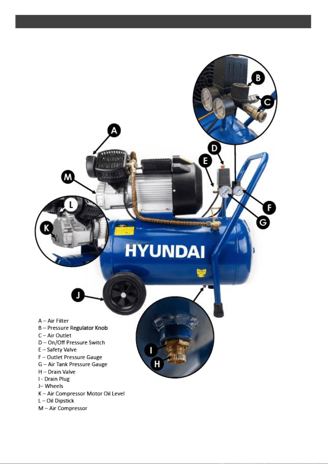
FEATURES
9
10
3.0
NOTE
Before assembly, make sure the air tank is not damaged.
Inspect all parts for damage and check that all pipes are firmly attached.
DO NOT use the air compressor if any damage is found.
If damaged contact your dealer.
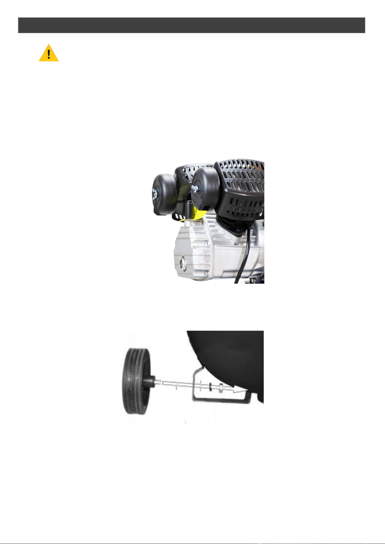
Attach both air filters to the top of the motor heads by screwing in to place.
Secure with the supplied butterfly nuts
3.1 Attach the wheel kit by sliding the washer onto the axle bolt.
3.2 Pass the bolt through the wheel and mounting point on the compressor and secure
in place.
3. ASSEMBLY
11
WARNING
Seek assistance when removing the compressor from its packaging.
4.0 Remove the compressor from its packaging and inspect for any damaged parts.
If anything is found to be missing or damaged, contact your supplier.
4.1 Take care to transport the compressor correctly, do not overturn it or lift it with hooks
or ropes.
4.2 Position the compressor on a flat, level surface or with a maximum permissible
inclination of 10°.
4.3 Site in a well-ventilated area.
4.4 If the surface is inclined and smooth, check if the compressor moves whilst in operation.
4.5 If the surface is in a raised position, make sure the compressor cannot fall, securing
it in a suitable way.
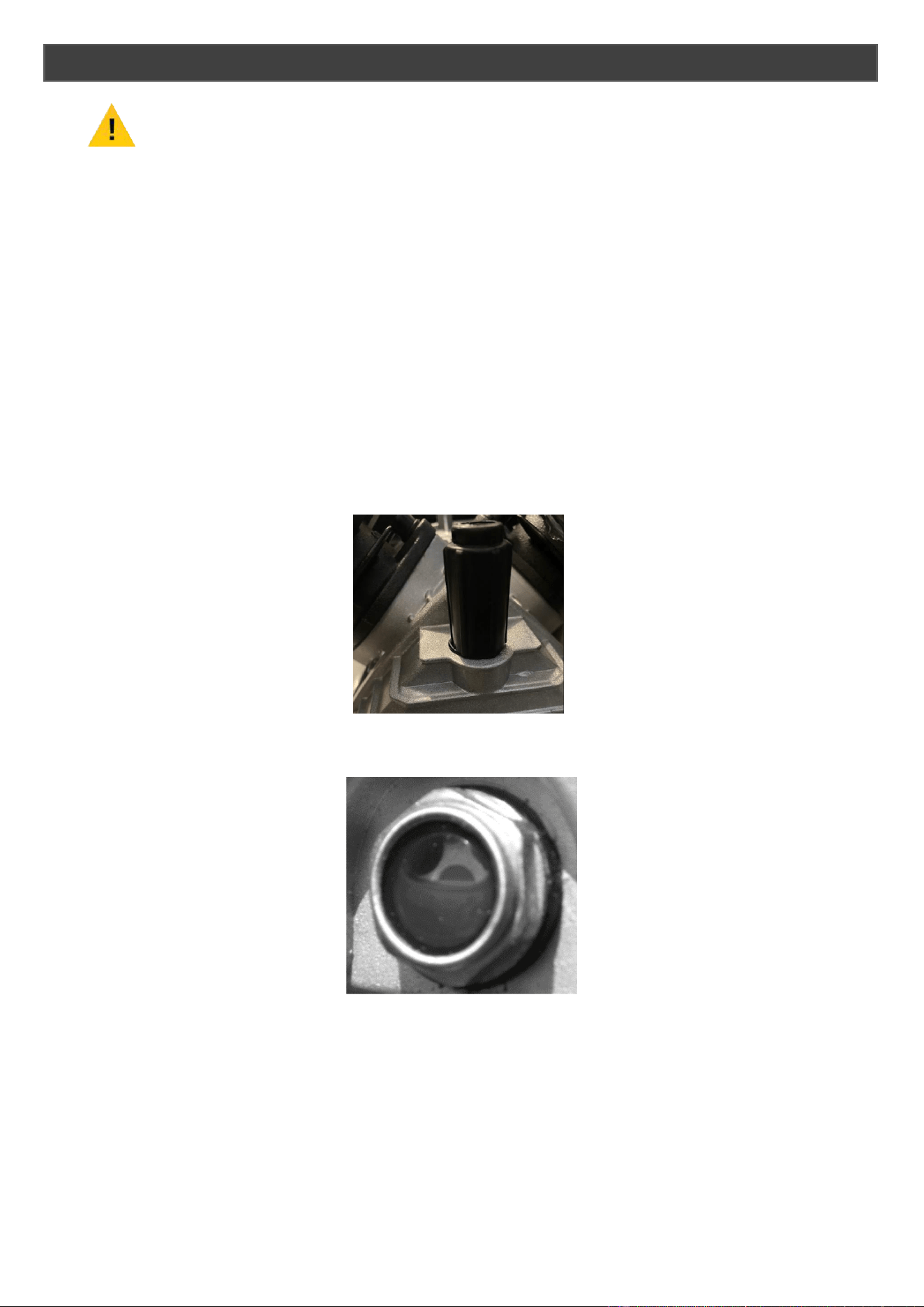
4.6 Remove the transit plug from the oil hole and replace with the breather plug.
4.7 Check the oil level sits in the red circle of the oil glass sight window.
4.8
4.9
4.10
4.11
Connect your air supply hose to a ¼” male universal or industrial quick connector
coupler.
Connect the male quick connect coupler to the female quick connect coupler located
on the air compressor.
Make sure the drain valve is off and that the pressure switch is in the OFF position.
Keep the voltage within ±4% of the rated value.
Insert the power supply cord into the power supply socket.
4. PREPERATION

12
4.10
4.11
4.12
4.13
4.14
4.15
4.16
4.17
NOTE
Before using the air compressor for the first time, complete a test run as follows:
Turn the power switch to the OFF Position.
Check the oil level is in the red circle of the glass sight window.
Plug the power supply cord into a power supply socket.
Start the air compressor by turning the power switch to the ON position.
The pressure gauge reading will slowly rise as pressure increases inside the air tank.
When the gauge reading reaches working pressure, the pressure switch will
automatically turn the power off.
This indicates the compressor is working normally.
Turn the power switch to the OFF position, unplug the power supply cord and
release the air in the tank by twisting the air drain valve.
If the compressor is not working properly, the pressure gauge will indicate that there
is a decrease in pressure in the air tank.
If there is an air leak from the compressor the pressure in the air tank decreases, the
pressure switch resets and the motor automatically turns back on.
5.0 Check that the power switch is in the OFF position.
5.1 Attach the air hose to the ¼” quick disconnect coupler.
5.2 Close the drain valve and ensure the air filter is installed.
5.3 Close the drain valve.
5.4 Check the oil level.
5.5 Plug the compressor in to a working plug socket.
5.6 Turn the power switch to the ON position.
5.7 Allow the motor to run and fill the tank until the motor turns off.
5.8 To regulate the air flow: While the air compressor is running, turn ON your tool and
turn the regulator knob to the right increasing the pressure.
Turn the pressure up until the desired pressure is reached.
5.9 Operate air tool normally.
TEST RUN
5. STARTING PROCEDURE

13
6.0 Turn the power switch to the OFF position.
6.1 Unplug the compressor.
6.2 Reduce the pressure in the air tank through the air supply hose.
7.0 To determine the correct working pressure and air flow requirements for any piece
of equipment, check the corresponding manual.
7.1 Be aware that the air flow figure stated on tools and accessories refers to ‘free air
delivery’ and not the piston displacement of the compressor.
7.2 When adjusting the regulator, always adjust up to the required pressure.
7.3 After fitting the desired coupling to the outlet valve, connect an air hose and hook up
to an air system
An outlet regulator is necessary to use air equipment direct from the compressor.
7.4 At the end of each working day, drain any moisture from the main tank.
7.5 Place a container under the drain plug and then carefully unscrew it anti-clockwise.
7.6 DO NOT allow moisture to accumulate in the tank as this will corrode the inside of
the tank and affect the pressure rating of the tank.
WARNING
Service and maintenance must be performed by an authorised agent.
DO NOT tamper with, or attempt to adjust the pressure switch. Before moving or
carrying out any maintenance on the compressor, make sure that the switch is
OFF and the air tank pressure has been vented and the compressor allowed to
cool down for a period of time.
8.0 You should drain the tank at the end of each day.
8.1 Place a suitable container capable of holding water, underneath the compressor.
6. STOPPING PROCEDURE
7. USING THE MACHINE
8. MAINTENANCE
DRAINING THE AIR TANK

8.2 With compressed air in the tank, slowly turn the drain knob to the open position.
The water in the tank will drain out.
8.3 Once the water has drained, turn the drain knob to the closed position.
8.4 Draining the tank reduces the risk of corrosion inside the tank.
8.5 The air filter is designed to reduce noise and help prevent particulates in the air from
entering and damaging the air compressor.
8.6 After being used for a period of time, the air filter will become clogged.
This will reduce the air intake capabilities of the compressor, reducing performance.
Therefore, the air filter must be cleaned or replaced regularly.
8.7 Open the cover on the air filter and remove the filter element.
8.8 Inspect the filter element and if damaged or worn, replace immediately.
8.9 Blow the dirt from the air filter from the inside out.
You can use a low pressure airline to do this.
8.10 Reinstall the air filter.
8.11 A small leak in any hose or connection will reduce the air compressors performance.
8.12 To test for leaks, spray a small amount of soapy water on the area suspected of
leaking.
If soap bubbles appear, replace the broken part.
8.13 Clean the compressor with a soft brush or moist cloth.
8.14 DO NOT use a pressure washer or hose pipe as water can penetrate the motor
and cause failure that will not be covered by the warranty.
8.15 DO NOT use solvent based cleaning products, these could damage parts.
8.16 Turn off the power and wrap the power cord around the compressor.
8.17 Pull the relief valve and release all the pressure from the air tank.
8.18 Clean the air compressor to remove all dirt and dust.
8.19 Cover the air compressor with a cover to protect the unit from dust and moisture.
8.20 DO NOT stack or store other items on top of or around the air compressor.
14
AIR FILTER
LEAK TESTING
CLEANING
STORAGE

15
PROBLEM
POSSIBLE CAUSE
POSSIBLE SOLUTION
Pressure drop in the tank
Air leaks at the connections
Let the compressor build up
pressure in the tank to
maximum pressure if possible.
Brush soapy water on the air
connections and look for air
bubbles. Tighten leaky
connections. If the problem
persists, contact your service
dealer
The unloader valve leaks when
the compressor is idle
Unloader valve seal is
defective
Let the air in the air tank flow
out until all the pressure is
released. Then remove the
unloader valve plug and clean
the valve seal. If necessary,
replace the seal and then
reinstall
The compressor stopped and
won’t restart
The thermal protector turned
on because the motor is
overheating
Check the main voltage
corresponds to the air
compressor specifications. An
extension cord that is under
rated or too long can cause
voltage drop and cause the
motor to overheat.
Allow the motor to cool down.
Motor windings have burnt out
Contact your service dealer
The motor does not start or
starts slowly
Low voltage supply to the
motor
Check that the main voltage
corresponds to the air
compressors specification.
An extension cord that is under
rated or too long can cause
voltage drop. Use a heavy duty
extension cord.
Ensure that the air compressor
is plugged into a fully
functioning power outlet.
The compressor is noisy
Compressor head gasket or
reed valve is faulty
Stop the compressor and
contact your service dealer
The compressor does not
reach the maximum pressure
Compressor head gasket or
reed valve is faulty
Stop the compressor and
contact your service dealer
The compressor does not
seem to deliver as much air as
it did when new and/or the
compressor shuts off with a
much shorter time period
The pressure switch needs
adjusting
Stop the compressor and
contact your service dealer
The tank is full of water due to
condensation
Open the drain valve and
release the water from the tank
The motor pump unit does not
stop when the tank pressure
reaches maximum working
pressure
Pressure switch defective or
requires adjusting
Stop the compressor and
contact your service dealer
9. TROUBLESHOOTING

16
MODEL
HY3050V
HY30100V
Power – kW / HP
2.2 / 3
2.2 / 3
Displacement – L/min
396 396
CFM
11.8
11.8
Pressure – Bar / PSI
8 / 115
8 / 115
Tank Size – L
50
100
RPM
2850
2850
Dimensions – mm (LxWxH)
740 x 380 x 740
115 x 400 x 740
Weight – Kg
40 52.5
10. SPECIFICATION
Sound Level - dB 95 95
17
11.0 We do not offer a take back scheme for the recovery of Waste Electrical Electronic
Equipment (WEEE) & Batteries.
Instead the responsibility to dispose of WEEE and or Batteries is passed onto you by
us.
So when it becomes necessary to dispose of your machine you must take it to your
local Civic Amenity Site.
For further information please contact your local Authority for disposal advice.
11.1 You MUST make sure that all unused oil and fuel is disposed of correctly either
beforehand or at your local Civic Amenity Site.
Under NO circumstances must any fuel or oil be put down drains.
11.2 Certain products contain WEEE waste which should be disposed
of in your domestic waste.
11.3 You MUST recycle WEEE in accordance with your local authority or
recycling centre.
11.4 Certain products contain batteries which should not be disposed of
in your domestic waste.
11.5 You MUST recycle batteries in accordance with your local authority or recycling
centre.
11.6 Unwanted packaging and materials should be stored and taken to a recycling centre
so it can be disposed of in a manner which is compatible with the environment.
11.7 The following symbol means that you should ‘Reduce – Reuse -
Recycle’.
11.8 We are a member of the VALPAK National Compliance Scheme and our registration
number is RM08660.
11.9 For further information about disposal please contact your Local Authority.
11.10 You can also get more advice and guidance about recycling at the following website
http://recycle-more.co.uk
11.11 Should you pass this product on to another user either sold or loaned, you MUST
pass on this user manual.
This will make sure that all other users can use and maintain this machine safely.
11. RECYCLING AND PRODUCT DISPOSAL
Declaration Of Conformity
Importer
and Authorised Representative
Genpower Ltd
Isaac Way, Pembroke Dock, SA72 4RW
Country of Origin: China
Description: Air Compressor
SKU Code: HY3050V, HY30100V
Date of Issue: 28/05/2020
Regulations
and Directives of Compliance
2006/42/EC - The Machine Directive
2014/30/EU - Annex ll Electromagnetic Compatibility Directive
2000/14/EC – Noise Emissions in the Environment by Equipment for use outdoors
2014/29/EU Article 13 -2(b) (ii)
2014/68/EU - The European Pressure Equipment Directive (PED)
2011/65/EU – RoHS Directive
REFERENCES
TO THE RELEVANT HARMONISED SAFETY STANDARDS USED OR REFERENCES TO
THE
OTHER TECHNICAL SPECIFICATIONS IN RELATION TO WHICH CONFORMITY IS DECLARED:
EN 61000
-6-3:2007/A1:2011/AC:2012 - Electromagnetic compatibility (EMC) - Part 6-3:
Generic standards
- Emission standard for residential, commercial and light-industrial
environments
EN IEC 61000
-6-1:2019 - Electromagnetic compatibility (EMC) - Part 6-1: Generic standards -
Immunity standard for residential, commercial and light
-industrial environments
EN IEC 61000
-3-2:2019 - Electromagnetic compatibility (EMC) - Part 3-2: Limits - Limits for
harmonic current emissions (equipment input current ≤16 A per phase)
EN 61000
-3-3:2013/A1:2019 -Electromagnetic compatibility (EMC) - Part 3-3: Limits -
Limitation
of voltage changes, voltage fluctuations and flicker in public low
-
voltage supply systems, for
equipment with rated current <= 16 A per phase and not subject to conditional connection
EN ISO 12100:2010
- Safety of machinery - General principles for design -
Risk assessment and
risk reduction (ISO 12100:2010)
EN 1012
-1:2010 - Compressors and vacuum pumps - Safety requirements - Part 1: Air
compressors
Statement
of Declaration
We the importer and authorised representative of the product described confirm
conformity within the provisions of applicable regulations and directives listed within this
document.
Signed
on Behalf of Genpower Ltd
Place of Issue: Genpower Ltd
Signatory Name: Roland Llewellin
Position: Managing Director:

19
13.0 POSTAL ADDRESS Genpower Ltd, Isaac Way,
London Road, Pembroke Dock,
Pembrokeshire.
SA72 4RW. UK.
13.1 TELEPHONE +44 (0) 1646 687880
13.2 FAX +44 (0) 1646 686198
13.3 SUPPORT
13.4 WEBSITE
www.hyundaipowerproducts.co.uk
14.0
Proof of purchase will be required before you make a warranty claim.
Full warranty terms and conditions can be found on the HYUNDAI POWER
PRODUCTS website:
www.hyundaipowerproducts.co.uk
15.0 Our manuals are constantly being reviewed and updated.
However if you find and error, omission or something you find unclear, please
contact your dealer for assistance.
15.1 Our latest manuals are also placed online.
15.2 We reserve the right to make any modifications without prior notice whenever
necessary.
13. CONTACT DETAILS
14. WARRANTY
15. MANUAL UPDATES
For Inquiries, Please Contact:
GENPOWER LTD
Isaac Way, London Road,
Pembroke Dock, UK, SA72 4RW.
T: +44 (0) 1646 687 880
E: info@hyundaipowerproducts.co.uk
www.hyundaipowerproducts.co.uk
Imported / Distributed by Genpower Ltd for
the United Kingdom & Ireland
Licensed by Hyundai Corporation Holdings, Korea