INSTALLATION GUIDE / USER MANUAL
PowerZone 252 • PowerZone 504 • PowerZone 1004
Technical and Safety Notices
Please read the following important technical, safety
and environmental notices before installing and using
your amplier.
Technical Notices
All reasonable design and engineering steps have been taken
to ensure that these ampliers always perform satisfactorily
in their intended application and environment and will provide
appropriate levels of support to ensure that all reasonable
customer needs and expectations are met. Such support
however is contingent on the following provisions.
1. These ampliers are Class-I products and should be installed
with a mains cable including the required earth connection to
comply with the Safety Class-I.
2. These ampliers are intended for professional audio
applications and should always be installed and operated by
competent and qualied personnel. Amplier damage or failure
caused by installation or operational errors may invalidate
support, warranty or guarantees of performance.
3. These ampliers are intended for professional use only
and are not suitable for use in locations where they may be
accessible to minors.
4. These ampliers are intended to be used specically for
the amplication of audio signals and for connection to
conventional moving-coil loudspeaker systems. Use of these
ampliers for amplication of signals outside the audio
band (20Hz to 20kHz) or to drive transducers other than
conventional moving-coil loudspeakers may invalidate support,
warranty or guarantees of performance.
5. These ampliers should only be used within professionally
installed and congured audio systems comprising input
and output ancillary equipments that is known to be of an
appropriate level of performance and in good operating
condition. Any damage to, or unsatisfactory performance from,
these ampliers caused by inadequate or failed input or output
ancillaries may invalidate support, warranty or guarantees of
performance.
6. These ampliers are intended to be installed and operated
indoor in a controlled environment (pollution degree, PD2)
within an ambient temperature range of 0°C to 40°C. These
ampliers are not intended for use above 2000 meters above
sea level. Ampliers installation or operated in environments
outside these limits may invalidate support, warranty or
guarantees of performance.
7. Specic warranty terms are the responsibility of the amplier
re-seller.
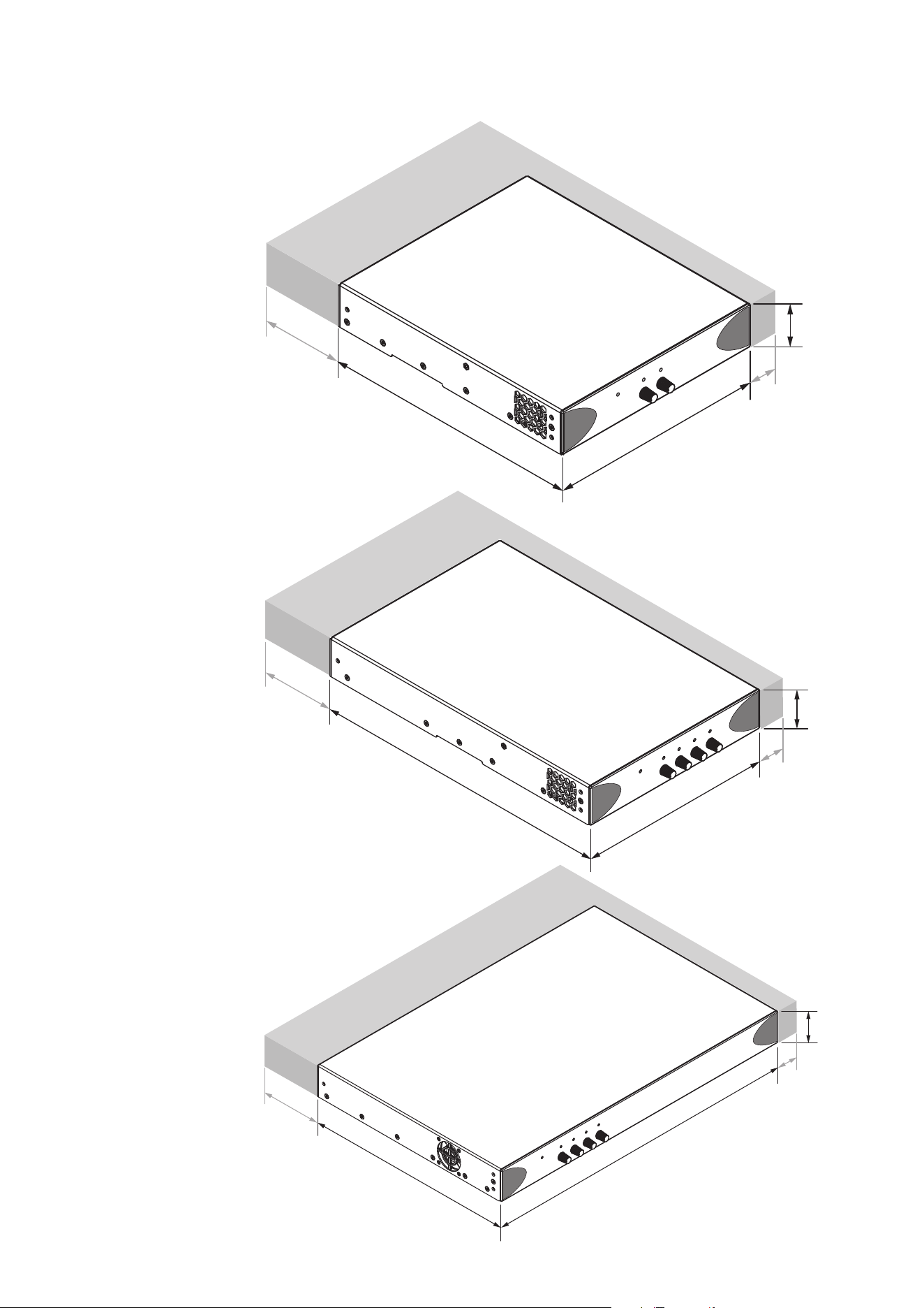
Safety and Environmental Notices
Note: The intent of the lightning ash with arrowhead symbol
in a triangle is to alert the user to the presence of uninsulated
“dangerous” voltage within the product’s enclosure that may be of
sufcient magnitude to constitute a risk of electric shock to humans.
Note: The intent of the exclamation point within an equilateral
triangle is to alert the user to the presence of important safety, and
operating and maintenance instructions in this manual.
WARNING! TO PREVENT FIRE OR ELECTRIC SHOCK,
DO NOT EXPOSE THIS EQUIPMENT TO RAIN OR
MOISTURE.
Ambient Temperature Note: If this
equipment is operated in a conned or
multiple rack installation, the internal
ambient operating temperature
may exceed the external ambient
temperature. It is important to ensure in
these circumstances that the published
maximum operating temperature for the
equipment is not exceeded.
Reduced Air Flow: Ensure that rack or
other closed installation does not restrict the cooling
airow required for safe and reliable operation of the
equipment.

Technical and Safety Notices
Important Safety Instructions
1. Read these instructions.
2. Keep these instructions.
3. Heed all warnings.
4. Follow all instructions.
5. Do not use this apparatus near water.
6. Do not submerge the equipment in water or liquids.
7. Do not use any aerosol spray, cleaner, disinfectant or
fumigant on, near or into the equipment.
8. Clean only with a dry cloth.
9. Do not block any ventilation opening. Install in accordance
with the manufacturer’s instructions.
10. Do not install near any heat sources such as radiators, heat
registers, stoves, or other apparatus (including ampliers)
that produce heat.
11. To reduce the risk of electrical shock, the power cord shall
be connected to a mains socket outlet with a protective
earthing connection.
12. Do not defeat the safety purpose of the polarized or
grounding type plug. A polarized plug has two blades with
one wider than the other. A grounding type plug has two
blades and a third grounding prong. The wide blade or the
third prong are provided for your safety. If the provided
plug does not t into your outlet, consult an electrician for
replacement of the obsolete outlet.
13. Protect the power cord from being walked on or pinched
particularly at plugs, convenience receptacles, and the
point where they exit from the apparatus.
14. Do not unplug the unit by pulling on the cord, use the plug.
15. Only use attachments/accessories specied by the
manufacturer.
16. Unplug this apparatus during lightning storms or when
unused for long periods of time.
17. Refer all servicing to qualied service personnel. Servicing
is required when the apparatus has been damaged in any
way, such as power supply cord or plug is damaged, liquid
has been spilled or objects have fallen into the apparatus,
the apparatus has been exposed to rain or moisture, does
not operate normally, or has been dropped.
18. The appliance coupler, or the AC Mains plug, is the AC
mains disconnect device and shall remain readily accessible
after installation.
19. Adhere to all applicable, local codes.
20. Consult a licensed, professional engineer when any
doubt or questions arise regarding a physical equipment
installation.
Environmental Statement
This product complies with international
directives, including but not limited to the
Restriction of Hazardous Substances (RoHS)
in electrical and electronic equipment, the
Registration, Evaluation, Authorization and
restriction of Chemicals (REACH) and the
disposal of Waste Electrical and Electronic Equipment (WEEE).
Consult your local waste disposal authority for guidance on
how properly to recycle or dispose of this product.

Introduction and Overview
1. Introduction
The ampliers described in this user manual have
been designed to provide congurable, consistent and
reliable high performance audio power amplication
for commercial and entertainment applications. Please
read this installation and operation manual fully
before installing and using an amplier. If you have any
questions regarding amplier conguration, installation
or operation please contact the appropriate customer
support portal.
Following this introduction, the manual is divided into sections
covering the following topics:
• Overview
• Carton Contents
• Conguration
• Installation
• Connections
• Operation
• Specications
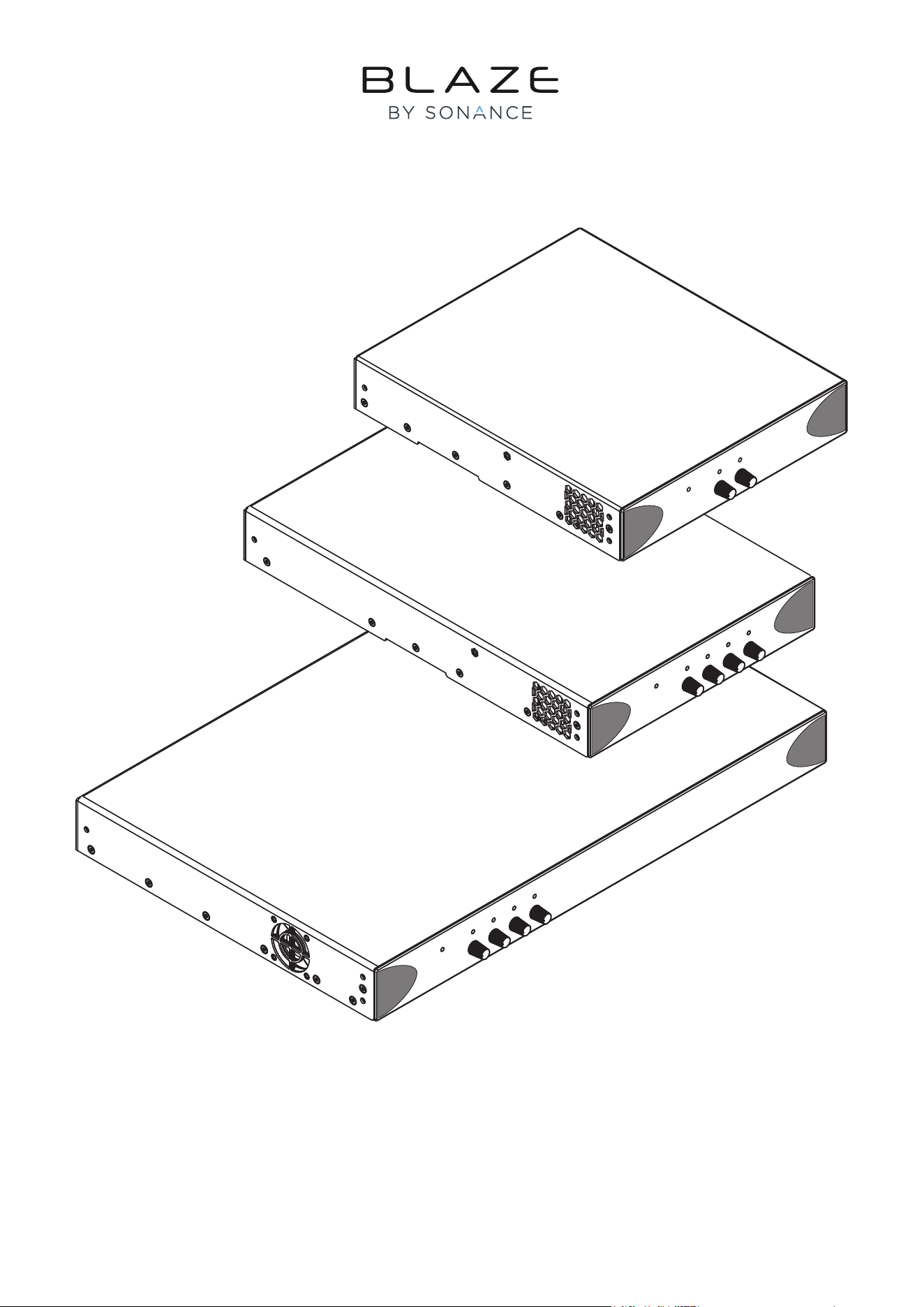
2. Amplier Overview
The PowerZone 252 amplier is a half width 1U rack format,
two channel audio power amplier that can drive both
conventional low impedance (4Ω to 16Ω - Low-Z) loudspeaker
loads and constant voltage (70V/100V - Hi-Z) transformer
coupled loudspeaker loads. Each output channel can be
independently congured to drive either Low-Z or Hi-Z loads.
The PowerZone 252 amplier is capable of a maximum
simultaneous output of 125 Watts per channel into both Low-Z
or 70V/100V Hi-Z loads but also incorporates automatic
power sharing technology that enables 250 Watts to be shared
proportionately across the output channels.
The PowerZone 504 amplier is a half width 1U rack format,
four channel audio power amplier that can drive both
conventional low impedance (4Ω to 16Ω - Low-Z) loudspeaker
loads and constant voltage (70V/100V - Hi-Z) transformer
coupled loudspeaker loads. Each output channel can be
independently congured to drive either Low-Z or Hi-Z
loads. The PowerZone 504 amplier is capable of a maximum
continuous simultaneous output of 125 Watts per channel
into both Low-Z or Hi-Z loads but also incorporates automatic
power sharing technology that enables 250 Watts to be shared
proportionately across each pair of output channels.
The PowerZone 1004 amplier is a 1U rack format, four
channel audio power amplier that can drive both conventional
low impedance (4Ω to 16Ω, - Low-Z) loudspeaker loads and
constant voltage (70V/100V - Hi-Z) transformer coupled
loudspeaker loads. Each output channel can be independently
congured to drive either Low-Z or Hi-Z loads. The PowerZone
1004 amplier is capable of a maximum output of 250 Watts
per channel into both Low-Z or Hi-Z loads.
Channel gain control knobs and status indicators are located
on the front panel. Signal input and output connections are
accomplished via ‘Euro Block’ connectors and operational
congurations are set up through a DIP switch module located
on the amplier rear panel. A rear panel GPIO (General
Purpose In/Out) connector is also provided that enables some
amplier functions to be controlled or monitored remotely.
The ampliers have no mains power switch and are operational
as soon as mains power is connected. The ampliers should be
connected to switched mains sockets.
PowerZone amplier dimensions and features are illustrated in
Diagrams 1a, 1b and 1c. The ampliers are primarily intended
for installation in an equipment rack but can also be under-desk
or wall mounted, or used free standing. They are fan-cooled
and must be installed such that ventilation apertures are not
obstructed.
3. Carton Contents
PowerZone ampliers are shipped in a cardboard
carton containing the amplier unit, a mains cable
appropriate for the sales territory, an accessory pack,
and a document pack. The full contents is listed below.
• Amplier unit
• Mains power cable
• Input connector x 1 or 2
• GPIO socket connector
• Output connector x 1 or 2
• Adhesive rubber feet x 4
• Document pack
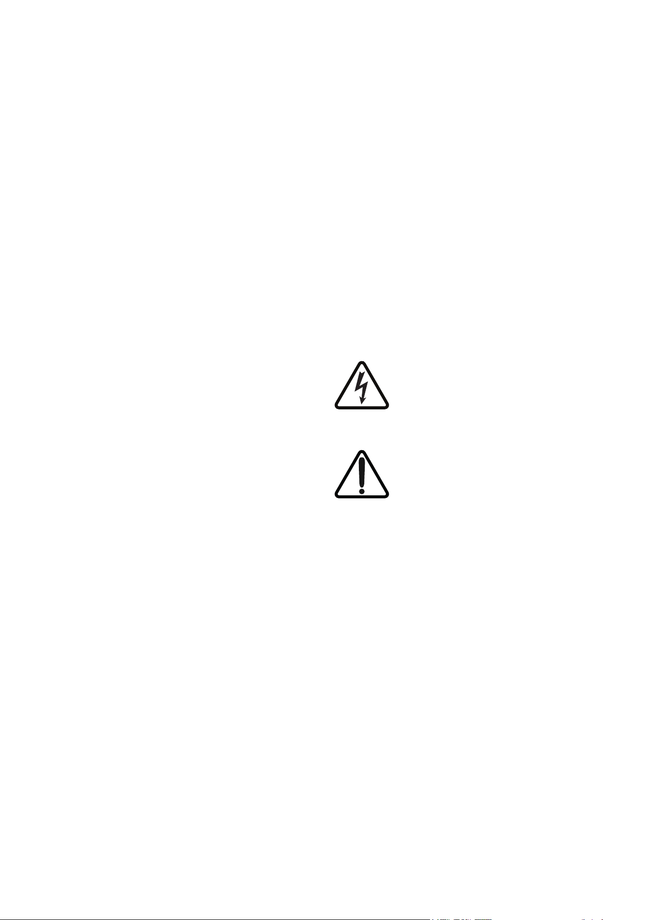
Overview
220 mm
8.7 in
44 mm
1.7 in
337 mm
13.3 in
80 mm
3.1 in
25 mm
1 in
292 mm
11.5 in
440 mm
17.3 in
44 mm
1.7 in
80 mm
3.1 in
25 mm
1 in
Diagram 1c
PowerZone 1004 dimensions.
Shaded area denes ventilation space.
Diagram 1b
PowerZone 504 dimensions.
Shaded area denes ventilation space.
260 mm
10.3 in
80 mm
3.1 in
220 mm
8.7 in
44 mm
1.7 in
25 mm
1 in
Diagram 1a
PowerZone 252 dimensions.
Shaded area denes ventilation space.
Conguration
4. Conguration
Amplier operational conguration is set up through
selections made on a rear mounted DIP switch module.
A GPIO (General Purpose In/Out) connector is also
provided that enables access to a variety of amplier
control and monitoring functions.
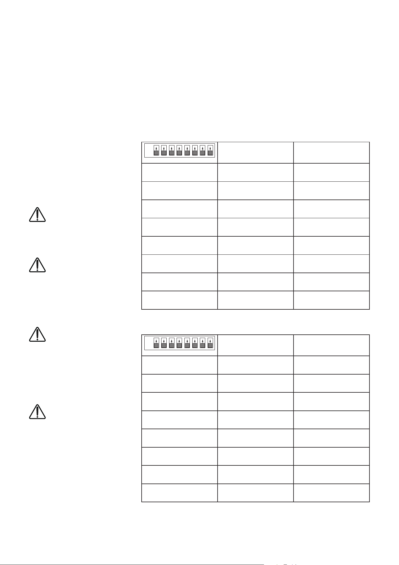
4.1 DIP Switch Conguration
The DIP switch module is illustrated
and its functions described for two and
four channel ampliers in the adjacent
matrices. DIP switch options are selected
(ON) when the switch is in the UP
position.
Note: When input ganging is ON,
each input channel is connected to
its equivalent output. When input
ganging is OFF, all outputs are
connected to input 1.
Note: When the front panel control
lock is ON, the last volume setting
will be frozen and further front panel
volume adjustment will have no
effect. External volume and standby
control via GPIO will remain
operational.
If the front panel volume controls
are turned up while the controls are
locked, the amplier volume will not
increase to match the new volume
level when the controls are unlocked.
To increase the volume, the controls
must rst be turned down to below
their previous level.
Note: An 80Hz second order
(12dB/octave) high-pass lter is
automatically applied to the signal
path of channels operating in Hi-Z
mode in order to prevent speaker
transformer core saturation.
Note: Use a small at blade screwdriver
blade to operate the DIP switches.
OFF
↓
ON
↑
SWITCH 1
Channel 1 in Low-Z mode Channel 1 in Hi-Z mode
SWITCH 2
Channel 2 in Low-Z mode Channel 2 in Hi-Z mode
SWITCH 3
Not Used Not Used
SWITCH 4
Not Used Not Used
SWITCH 5
70V Hi-Z mode
(for channels in Hi-Z mode)
100V Hi-Z mode
(for channels in Hi-Z mode)
SWITCH 6
Input ganging 1: All Input ganging 1:1
SWITCH 7
GPIO standby polarity NO
(Normally Open)
GPIO standby polarity NC
(Normally Closed)
SWITCH 8
Front panel control locked. Front panel control unlocked.
ON
OFF
1 2 3 4 5 6 7 8
OFF
↓
ON
↑
SWITCH 1
Channel 1 in Low-Z mode Channel 1 in Hi-Z mode
SWITCH 2
Channel 2 in Low-Z mode Channel 2 in Hi-Z mode
SWITCH 3
Channel 3 in Low-Z mode Channel 3 in Hi-Z mode
SWITCH 4
Channel 4 in Low-Z mode Channel 4 in Hi-Z mode
SWITCH 5
70V Hi-Z mode
(for channels in Hi-Z mode)
100V Hi-Z mode
(for channels in Hi-Z mode)
SWITCH 6
Input ganging 1: All Input ganging 1:1
SWITCH 7
GPIO standby polarity NO
(Normally Open)
GPIO standby polarity NC
(Normally Closed)
SWITCH 8
Front panel control locked. Front panel control unlocked.
ON
OFF
1 2 3 4 5 6 7 8
PowerZone 252 DIP switch functions
PowerZone 1004 and 504 DIP switch functions
Conguration
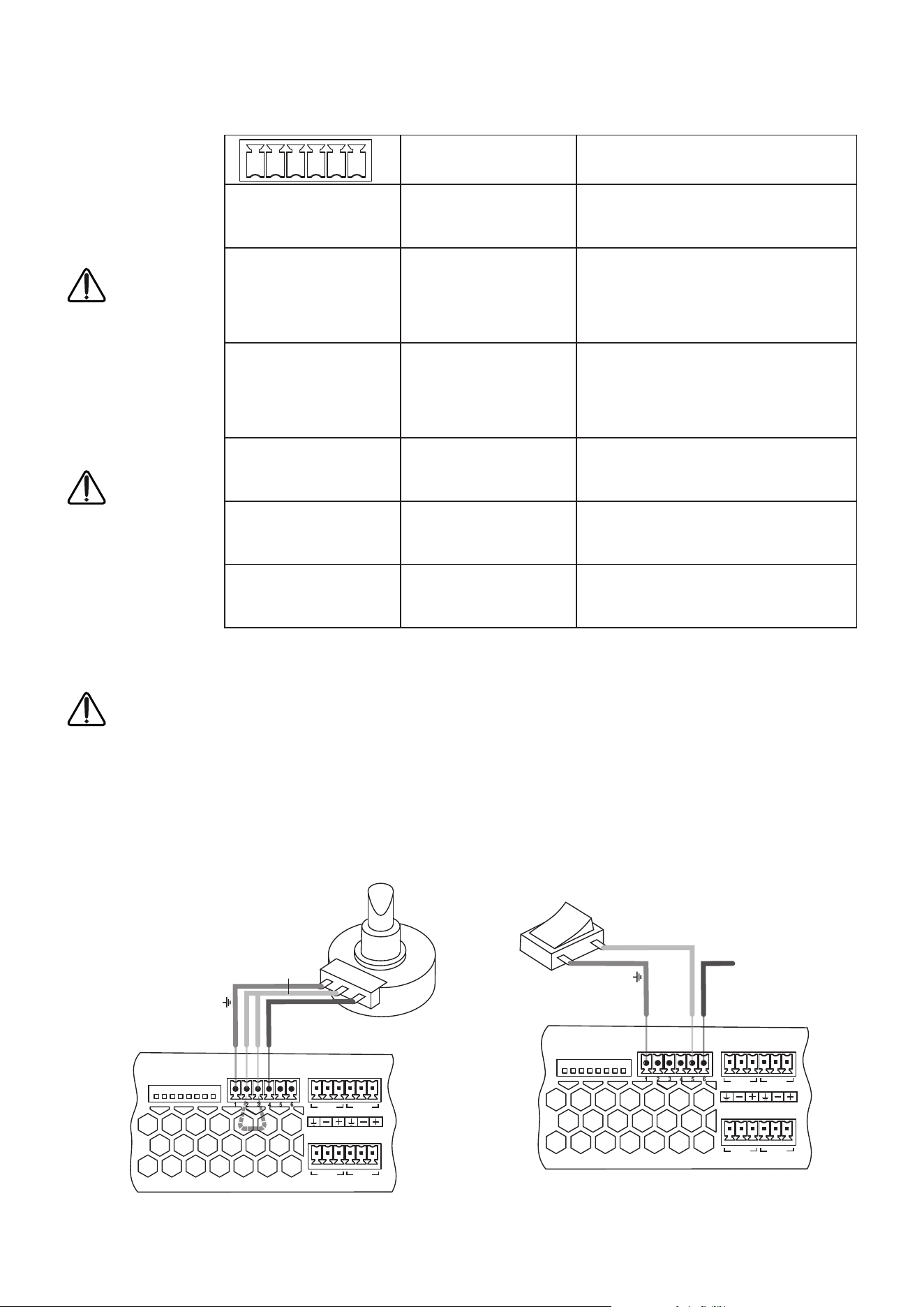
4.2 GPIO Functions
The GPIO connector
is illustrated and its
functions described in
the adjacent matrix.
Note: The GPIO
connector must
not be used for
any unintended
purpose. Amplier
damage may
result from
incorrect use of
GPIO.
Note: In order to
conform to EMC
specications,
shielded cable
must be used
when connecting
external
volume control
potentiometers
via GPIO.
Note: The GPIO GPO connection has an output impedance
of 1kΩ. Connected devices must be able to sink 3.3mA.
FUNCTION NOTES
GPIO GND (1)
Ground reference for all GPIO
pins
GPIO V12 (2)
Channel 1 & 2 additional gain
control.
Connect to a potentiometer (>10kΩ) wiper
between the VCC and GND pins. Diagram
2a below illustrates these potentiometer
connections. The maximum level available when
using GPIO control is dened by the front panel
gain control setting.
GPIO V34 (3)
Channel 3 & 4 additional
gain control (four channel
ampliers only).
Connect to a potentiometer (>10kΩ) wiper
between the VCC and GND pins. Diagram
2b below illustrates these potentiometer
connections. The maximum level available when
using GPIO control is dened by the front panel
gain control setting.
GPIO VCC (4)
Control voltage output.
Provides a 3.3Vdc control output (100Ω output
impedance) for up to two volume control
potentiometers (>10kΩ).
GPIO STB (5)
Remote standby control.
Pull to GND to engage or disengage standby mode
depending on DIP Switch 7 setting.
GPIO GPO (6)
System status indication.
+3.3Vdc indicates normal status, 0Vdc indicates
one or more channels in protection mode.
1 2 3 4 5 6
Diagram 2a
Potentiometer connections for remote
volume control via GPIO.
Note: Diagram 7d illustrates
use of the GPIO connector.
Diagram 2b
Connections for remote standby switch and
status indication via GPIO.
Note: Diagram 7d illustrates
use of the GPIO connector.
8
7
6
5
4
3
2
1
LoZ/HiZ-1
LoZ/HiZ-2
LoZ/HiZ-3
LoZ/HiZ-4
70V/100V
1:All/1:1
Stby No/Nc
Lck/Unlck
GND
VC34
+3V3
Stby
Fault
VC12
INPUT
CH1
CH3
CH2
CH4
Potentiometer
(>10kΩ)
Connect Wiper:
504/1004: VC12 for Channel 1 & 2
504/1004: VC34 for Channel 3 & 4
252: VC1 for Channel 1
252: VC2 for Channel 2
Ground
+3V3
Wiper
*Short the two VC inputs to control all channels
*
8
7
6
5
4
3
2
1
LoZ/HiZ-1
LoZ/HiZ-2
LoZ/HiZ-3
LoZ/HiZ-4
70V/100V
1:All/1:1
Stby No/Nc
Lck/Unlck
GND
VC34
+3V3
Stby
Fault
VC12
INPUT
CH1
CH3
CH2
CH4
+3V3 = operational
0V = fault
Switch open or closed toggles standby
depending on poition of DIP switch 7.
Ground
Fault
Standby
Installation
5. Installation
Note: It is important in all installations that the amplier mains
supply switch is easily accessible.
Note: The rack mounting and desk/wall mounting components
described and illustrated in Sections 5.1 to 5.3 are not supplied with
PowerZone ampliers but are available to purchase as accessories.
Contact your amplier re-seller for more information.
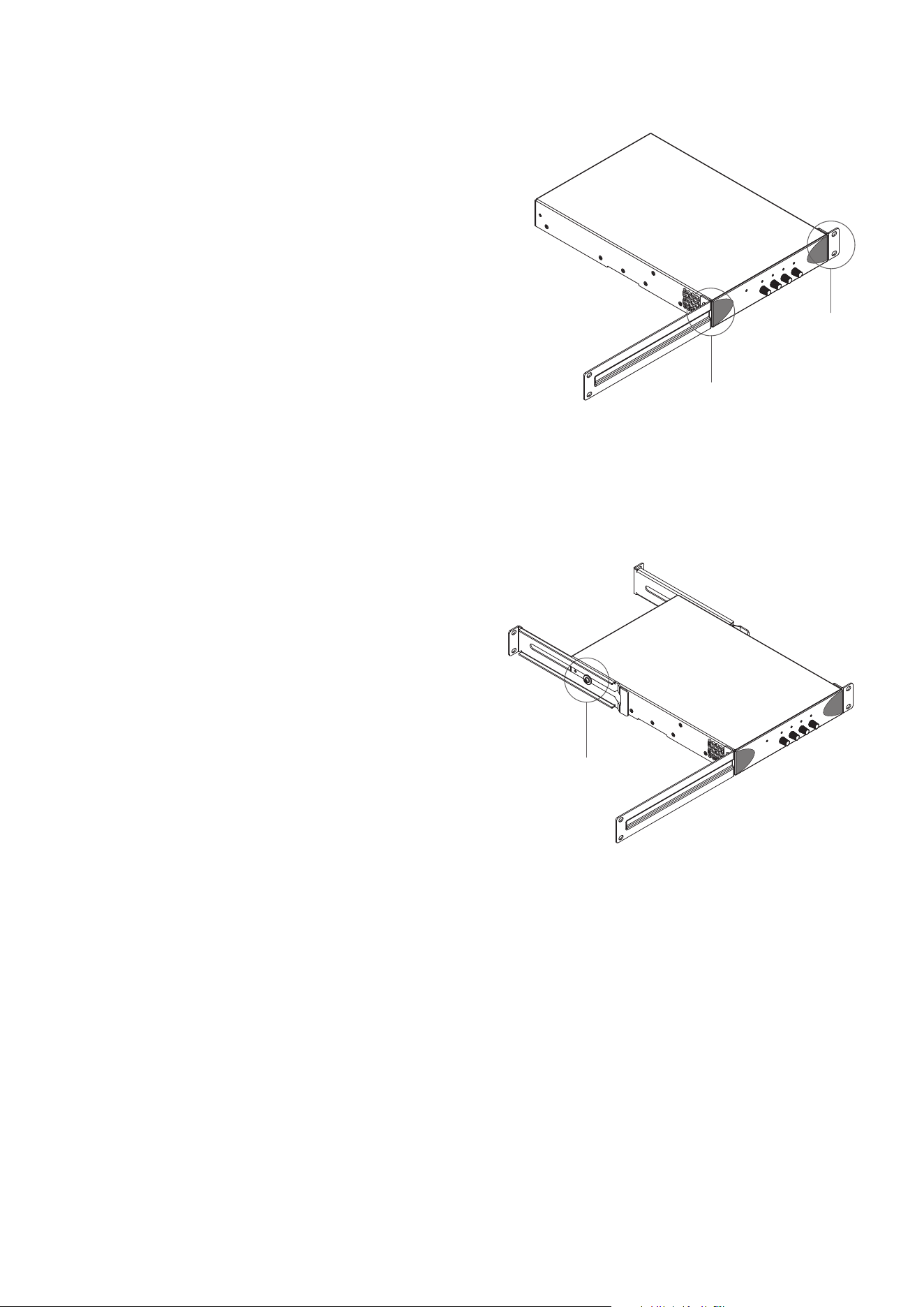
5.1 PowerZone 252 Mounting
The PowerZone 252 amplier is shipped without rack mount
hardware attached but can be congured for rack installation
using one standard rack ‘ear’ and one half-rack extension piece
as illustrated in Diagram 3a. The installation and equipment
rack should be congured to provide appropriate ventilation
airow space around the sides and rear of the amplier as
illustrated in as illustrated in Diagram 1a. Ventilation airow
space of at least 25 mm (1 in) should be maintained along at
least one side of the amplier at all times. Ventilation apertures
are also located on the rear panel of the amplier and must
not be obstructed. It is important to retain at least 80 mm (3.1
in) free space for airow behind the amplier rear panel.
In addition to rack mount ears, optional rack mount rear
support hardware is available and can be attached to the
amplier. Rear support hardware may be appropriate if
the amplier is to be used in a mobile rack or potentially be
subject to signicant movement. Diagram 3b illustrates the
use of rack mount rear support hardware.
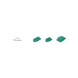
Multiple PowerZone 252 ampliers can also be mechanically
connected using accessory connecting plates. Diagram 3c
illustrates the use of connecting plates.
5.1 PowerZone 504 Mounting
The PowerZone 504 amplier is shipped without rack mount
hardware attached but can be congured for rack installation
using one standard rack ‘ear’ and one half-rack extension piece
as illustrated in Diagram 3a. The installation and equipment
rack should be congured to provide appropriate ventilation
airow space around the sides and rear of the amplier as
illustrated as illustrated in Diagram 1b. Ventilation airow
space of at least 25 mm (1 in) should be maintained along at
least one side of the amplier at all times. Ventilation apertures
are also located on the rear panel of the amplier and must not
be obstructed. It is important to retain at least 80 mm (3.1 in)
free space for airow behind the amplier rear panel.
In addition to rack mount ears, optional rack mount rear
support hardware is available and can be attached to the
amplier. Rear support hardware may be appropriate if the
amplier is to be used in a mobile rack or potentially be subject
Rack Ear +
2 x M4 x 8 csk
Half-rack extension +
2 x M4 x 8 csk
Diagram 3a
PowerZone 252/504 rack ear + half-rack extension.
Diagram 3b
PowerZone 252/504 rack support hardware.
2 positions.
Rear Support + Button +
1 x M4 x 8
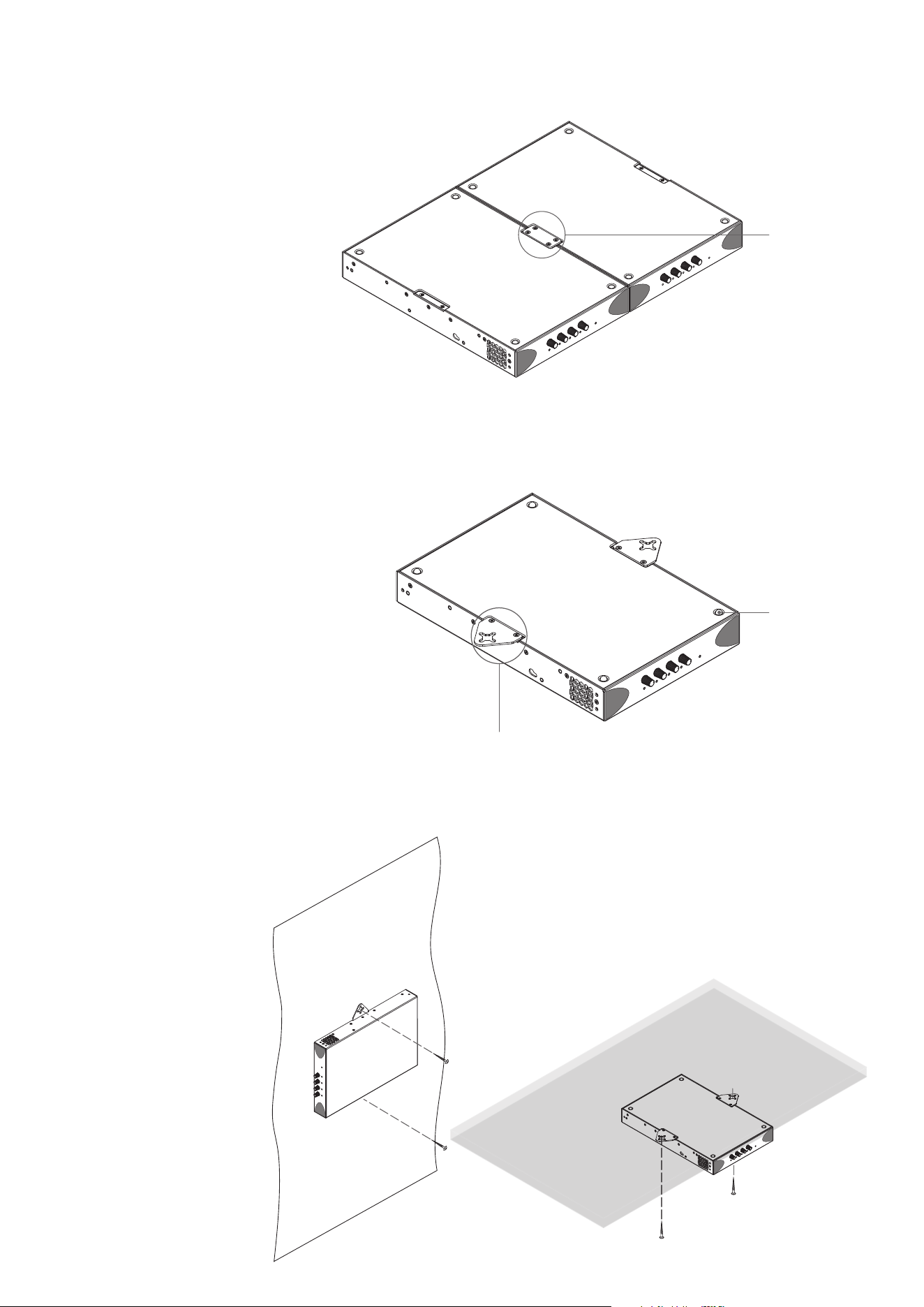
Diagram 3c
2 x PowerZone 504 with connection plate.
Connection Plate +
4 x M3 x 6 csk
Installation
Diagram 4a
PowerZone 252/504 with desk/wall mounting plate and
adhesive feet. 2 positions and 4 positions.
Diagram 4b
PowerZone 252/504 under-desk and wall mounted.
Note: Only permissable mounting orientation for on wall mounting!
5.3 Free-standing
If not to be installed in an equipment rack,
PowerZone ampliers can be placed free-standing
on a at surface. Adhesive rubber feet are supplied
for this purpose.
PowerZone 504 and PowerZone 252 ampliers
can also be attached to the underside of desks or
wall mounted using connecting plate hardware.
The adhesive rubber feet should also be used in
these circumstances to minimise the possibility
of vibration between the amplier and mounting
surface. Wall and desk mounting is illustrated in
Diagrams 4a and 4b.
It is important in any free standing installation that airow
through the amplier’s side
panel mounted fans and rear
panel ventilation apertures is
not compromised by adjacent
items. At least 80mm of free
space behind the amplier and
25mm along at least one side
should be retained at all times.
Mounting Plate +
2 x M3 x 6 csk
Adhesive Foot
to signicant movement. Multiple
PowerZone 504 ampliers can also be
mechanically connected using accessory
connecting plates. Diagrams 3b and
3c illustrate the use of rack mount rear
support hardware and connecting plates.
Installation
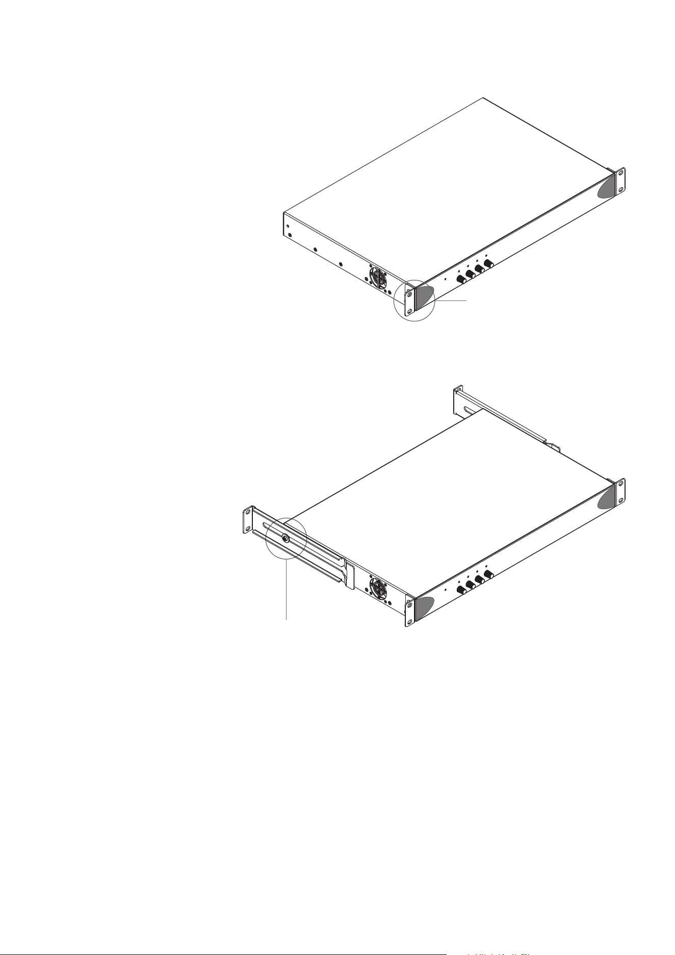
5.4 PowerZone 1004 Mounting
Note: The rear support components described and
illustrated in Sections 5.4 are not supplied with
PowerZone ampliers but are available to purchase as
accessories. Contact your amplier re-seller for more
information.
The PowerZone 1004 amplier is shipped with
rack mount ‘ears’ attached as illustrated in Diagram
5a and is primarily intended to be installed in an
equipment rack. The installation and equipment
rack should be congured to provide appropriate
ventilation airow space around the sides and
rear of the amplier as illustrated in Diagram 1c.
Ventilation airow space of at least 25 mm (1 in) should be
maintained along at least one side of the amplier at all times.
Ventilation apertures are also located on
the rear panel of the amplier and must
not be obstructed. It is important to retain
at least 80 mm (3.1 in) free space for
airow behind the amplier rear panel.
In addition to rack mount ears, optional
rack mount rear support hardware is
available and can be attached to the
amplier. Rear support hardware may
be appropriate if the amplier is to be
used in a mobile rack or potentially be
subject to signicant movement. Diagram
5b illustrates the use of rack mount rear
support hardware.
Rack Ear +
2 x M4 x 8 csk
Diagram 5a
PowerZone 1004 rack ears. 2 positions.
Rear Support + Button +
1 x M4 x 8
Diagram 5b
PowerZone 1004 rear support hardware.
2 positions.
Connections
6. Connections
Note: The micro USB socket located on amplier rear panels is
present for service and diagnostic purposes only.
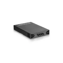
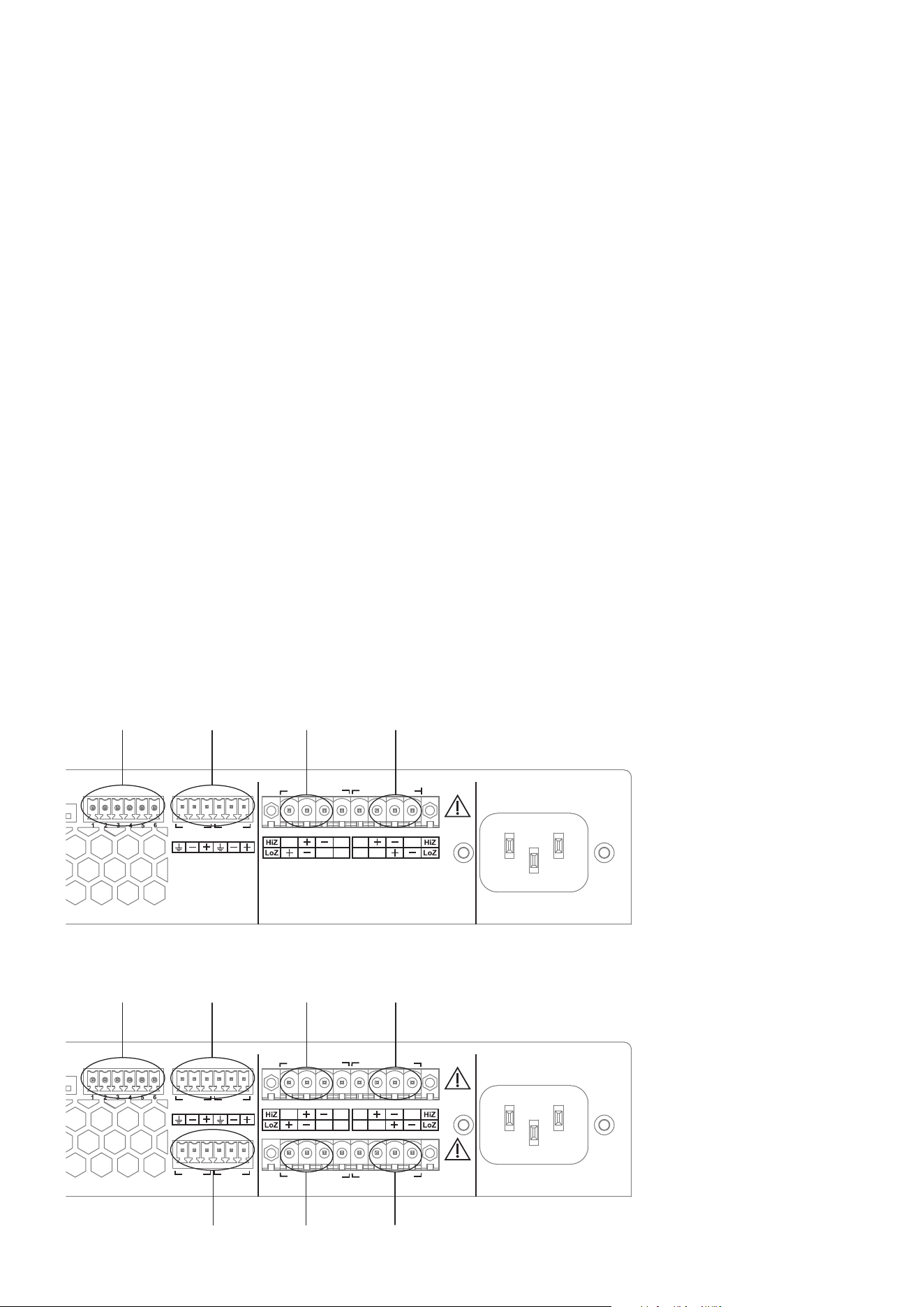
The amplier rear panel connection sockets are illustrated in
Diagrams 6a and 6b.
6.1 Mains Power Connection
PowerZone ampliers incorporate a power factor corrected
universal power supply and can be used with mains input
voltage from 100V AC to 240V AC, 50/60Hz. Use the mains
cable supplied with the amplier and connect it to a switched
mains supply. The power consumption of the ampliers is
300W, 150W and 75W for the PowerZone 1004, PowerZone
504 and PowerZone 252, respectively.
The ampliers have no mains power switch and are operational
as soon as mains power is connected. Ensure that all signal,
GPIO and output connections are made and that all DIP switch
options are selected appropriately before connecting the
amplier to mains power.
100 - 240 VAC~
50 - 60Hz / 150W
AC MAINS
INPUT
MAINTENANCE
OUTPUT
CLASS 2
WIRING
CLASS 2
WIRING
DESIGNED AND ENGINEERED IN DENMARK - MANUFACTURED IN CHINA
Input
Channel 1 & 2
Output
Channel 1
GPIO
Input
Channel 3 & 4
Output
Channel 2
Output
Channel 3
Output
Channel 4
CH3
CH4
CH1 CH2
CH1
CH3
CH2
CH4
8
7
6
5
4
3
2
1
LoZ/HiZ-1
LoZ/HiZ-2
LoZ/HiZ-3
LoZ/HiZ-4
70V/100V
1:All/1:1
Stby No/Nc
Lck/Unlck
GND
VC34
+3V3
Stby
Fault
VC12
Diagram 6b
PowerZone 1004 & PowerZone
504 connection sockets.
8
7
6
5
4
3
2
1
LoZ/HiZ-1
LoZ/HiZ-2
LoZ/HiZ-3
LoZ/HiZ-4
70V/100V
1:All/1:1
Stby No/Nc
Lck/Unlck
GND
VC34
+3V3
Stby
Fault
VC12
100 - 240 VAC~
50 - 60Hz / 150W
BLAZE AUDIO POWERZONE 252 | DESIGNED BY PASCAL IN COPENHAGEN | MANUFACTURED IN CHINA
AC MAINS
INPUT
CH1
CH2
MAINTENANCE
OUTPUT
CLASS 2
WIRING
Input
Channel 1 & 2
Output
Channel 1
GPIO
Output
Channel 2
CH1 CH2
Diagram 6a
PowerZone 252
connection sockets.
6.2 Input Connections
PowerZone amplier inputs are of balanced, line level format
with a input sensitivity of +4dBu (full output voltage swing/
sensitivity) in all modes. Input signal levels up to +24dBu can be
handled without input clipping.
Input connections to the ampliers are achieved via male ‘Euro
Block’ connectors. Connecting cables to the supplied female
input connectors is illustrated in Diagram 7a.
Note: If unbalanced audio sources are used, their negative and
conductor should be connected to both the negative and earth input
terminals.
6.3 Output Connections
Output connections from the ampliers are achieved via male
‘Euro Block’ connectors. Ensure that speaker connection
polarity is correct throughout the installation: positive (+)
amplier terminals should always be connected to positive
speaker terminals and negative (–) amplier terminals always
connected to negative speaker terminals.
Together with DIP switch conguration, the output connector
blocks provide connection options that enable channel
independent selection of Hi-Z or Low-Z mode. Connecting
cables to the supplied female output connector, and the
selection of Hi-Z or Low-Z connection options, are illustrated in
Diagrams 7b and 7c respectively.

Cable Gauge Table
Low-Z installations. 4Ω & 8Ω loads
Cable Gauge Table
70V Hi-Z installations. 125W & 250W power
Cable Gauge Table
100V Hi-Z installations. 125W & 250W power
Cable Cross Section
(mm
2
)
Cable Gauge
(US)
Max Cable Length
(metres, 4Ω load)
Max Cable Length
(metres, 8Ω load)
0.5 ≈20 2 5
0.75 ≈18 4 8
1.5 ≈16 6 12
2.0 ≈14 9 19
4.0 ≈12 14 30
Cable Cross Section
(mm
2
)
Cable Gauge
(US)
Max Cable Length
(metres,
(125W/channel)
Max Cable Length
(metres,
(250W/channel)
0.5 ≈20 84 42
0.75 ≈18 132 66
1.5 ≈16 210 105
2.0 ≈14 334 166
4.0 ≈12 532 265
Cable Cross Section
(mm
2
)
Cable Gauge
(US)
Max Cable Length
(metres,
(125W/channel)
Max Cable Length
(metres,
(250W/channel)
0.5 ≈20 171 85
0.75 ≈18 269 134
1.5 ≈16 430 215
2.0 ≈14 683 341
4.0 ≈12 1087 542
Connections
6.4 Speaker Cable Gauge
Speaker connection cable gauge should be
chosen appropriately to reect the type
of installation. The adjacent tables specify
the appropriate cable gauge for less than
0.5dB cable loss with different installation
types and cable lengths.
6.5 GPIO Connections
If any GPIO functionality is required,
cables will need to be connected to the
supplied GPIO connector. Connecting
cables to the supplied female GPIO
connector is illustrated in Diagrams 7d.
Note: The maximum recommended GPIO
cable length is 10m (32ft 10in)
Note: The GPIO GPO connection has an
output impedance of 1kΩ. Connected
devices must be able to sink 3.3mA.
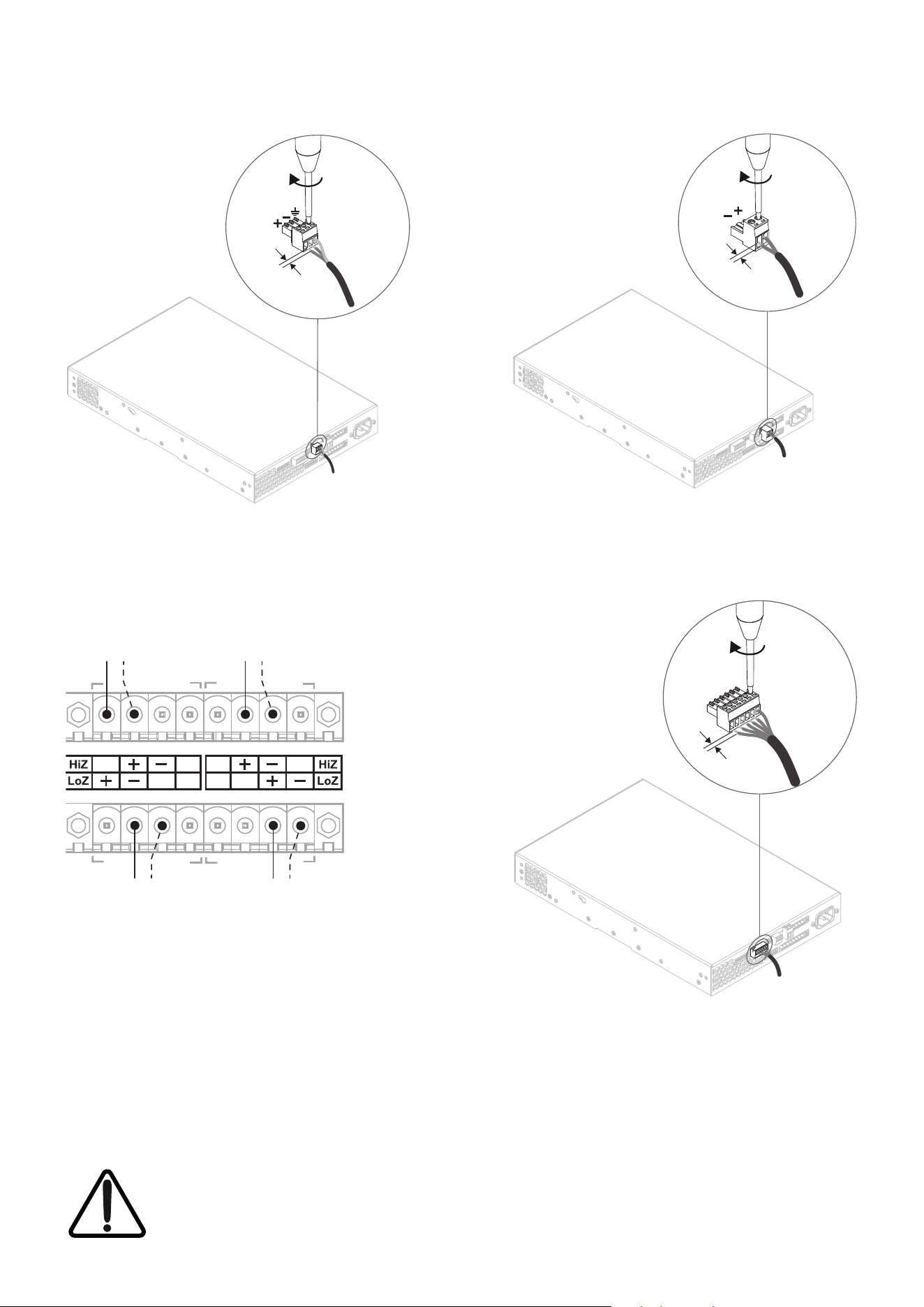
Hi-Z Connection
+ –
Low-Z Connection
+ –
+ –
Low-Z Connection
+ –
Hi-Z Connection
CH3
CH4
CH1 CH2
5 mm
5 mm
5 mm
Connections
Diagram 7a
Cable connections
to the input connector.
Diagram 7c
Example output connections.
Channel 1: Low-Z connection illustrated
Channel 2: Hi-Z connection illustrated
Channel 3: Hi-Z connection illustrated
Channel 4: Low-Z connection illustrated
Note: DIP switch options must be set appropriately.
Diagram 7b
Cable connections
to the output connector.
Diagram 7d
Cable connections
to the GPIO connector.
The exclamation point printed next to the output terminals of the ampliers is, in addition to the CLASS 2
WIRING text, intended to alert users to the risk of hazardous voltages. Output connectors that could pose a risk
are marked with the exclamation point. Do not touch the output terminals while the amplier is switched on.
Make all connections with the amplier switched off.
Operation
7. Operation
Once all connections have been made and DIP
switches set, the amplier can be connected to
mains power. After a short delay, and if an input
signal above -55dB is present on any input, the
front panel standby indicator will illuminate
green to indicate normal amplier operation.
Note: The ampliers will not switch on from standby mode
unless an input signal is present or the standby switch is toggled.
Set the channel gain controls appropriately in respect of the
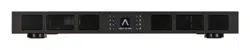
input signal level and required speaker volume. Diagrams
8a, 8b and 8c illustrate the front panel controls and
indicators.
Amplier outputs will mute if no input signal is
present for 10 minutes, and the amplier will switch
automatically to standby mode if no signal is present
on any input for more than 25 minutes. Standby mode
can also be triggered remotely via a switch connected
between the STB and GND GPIO connector pins.
Amplier cooling fan speed is temperature controlled. The fan
will switch off when the amplier enters standby mode.
7.1 Standby Indicator
The Standby Indicator changes colour to indicate
operational states:
Green: The amplier is in normal operation mode.
Red: The amplier is in sleep mode following no
input present for more than 10 minutes, or
in standby mode following a GPIO trigger.
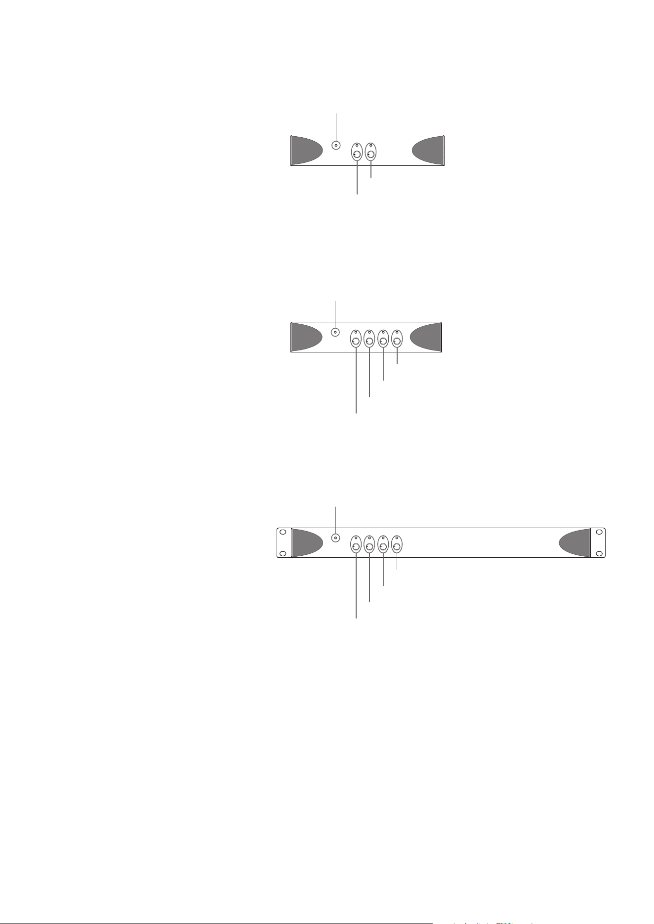
7.2 Signal Indicators
The Signal Indicators adjacent to each channel gain
control knob illuminate in different colours to indicate input
states:
Green: Signal present (> -55dB)
Orange: Output limiter active (0dB)
Red: Input overload, output protection operational or
amplier fault.
Standby indicator
Gain adjust and signal indicator – Channel 4
Gain adjust and signal indicator – Channel 3
Gain adjust and signal indicator – Channel 2
Gain adjust and signal indicator – Channel 1
Standby indicator
Gain adjust and signal indicator – Channel 4
Gain adjust and signal indicator – Channel 3
Gain adjust and signal indicator – Channel 2
Gain adjust and signal indicator – Channel 1
Diagram 8c
PowerZone 1004 front panel.
Diagram 8b
PowerZone 504 front panel.
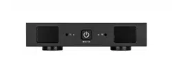
Standby indicator
Gain adjust and signal indicator – Channel 2
Gain adjust and signal indicator – Channel 1
Diagram 8a
PowerZone 252 front panel.
7.3 Automatic Power Sharing
The PowerZone 252 and PowerZone 504 incorporate a power
sharing feature.
PowerZone power sharing automatically shares the total power
available from the amplier’s internal power supply across each
pair of output channels. If one channel temporarily demands
more than the amplier’s continuous power rating while other
channel is demanding less, the excess power available from the
internal power supply is automatically made available to the
over-power channel. Power sharing optimises the amplier’s
ability to deliver maximum power into dynamic loudspeaker
loads when playing music programme material.

©2025 Sonance. All rights reserved. Sonance is a registered trademarks of Dana Innovations.
Due to continuous product improvement, all features and specifications are subject to change without notice.
For the latest Sonance product specification information visit our website at www.sonance.com.
SONANCE • 991 Calle Amanecer • San Clemente, CA 92673 USA • Phone: (949) 492-7777 • Technical Support: (949) 492-7777 • www.sonance.com • 07.01.25
Specications
Rev M 23/06/2025
Model PowerZone 252 PowerZone 504 PowerZone 1004
Total System Power 250 W 500 W 1000 W
Output Power @ 4/8Ω 2 x 125 W 4 x 125 W 4 x 250 W
Output Power @ 70/100V* 2 x 125 W 4 x 125 W 4 x 250 W
Powershare (up to)
Across all channels**
1 x 250 W 2 x 250 W N/A
Power Consumption 75W 150W 300W
Dimensions
44.5 x 220 x 262 mm
(1.75 x 8.66 x 10.31 in)
44.5 x 220 x 337 mm
(1.75 x 8.66 x 13.27 in)
44.5 x 440 x 292 mm
(1.75 x 17.32 x 11.50 in)
Weight 1.9 kg (4.2 lbs) 2.4 kg (5.3 lbs) 3.6 kg (7.9 lbs)
Output Circuitry UMAC™ Class D - full bandwidth PWM modulator with ultra-low distortion
Output Voltage 70 Vp / 140 Vpp (unloaded) / Bridged 140 Vp / 280 Vpp (unloaded)
Signal To Noise-Ratio > 100 dB (A-weighted, 20 Hz - 20 kHz, 8 Ω load)
THD+N (typical) < 0.05 % (20 Hz - 20 kHz, 8 Ω load, 3 dB below rated power)
Frequency Response 20 Hz - 20 kHz (+0/-0.25 dB (8 Ω load, 3 dB below rated power)
Protection Circuits Short circuit protection, DC protection, under voltage protection, temperature protection, overload protection
Power Supply
UREC™ universal mains switch mode power supply with Power Factor Correction (PFC)
and integral standby converter
Operating Voltage/
Frequency.
Universal Mains, 100-240V, 50-60Hz
Standby Consumption < 0.5 W (Energy Star & ErP 1275/2008/EC compliant)
Accessories
2x Rack ears (supplied with PowerZone 1004)
1x 1/2 rack plate extension
2x 1/2 rack mounting
2x Rear supports
Power Ratings 1% THD @ 120VAC and 230VAC
*100V line mode is @ -1dB (≈ 90 V)
**504 may only Powershare across Ch1/2 and Ch3/4