ERSB1
At ErgoAV, our goal is to add value to your AV experience by
providing the highest quality products and services in the industry.
We offer a 5-year warranty. If you have any questions or concerns,
please contact us.
Rev00
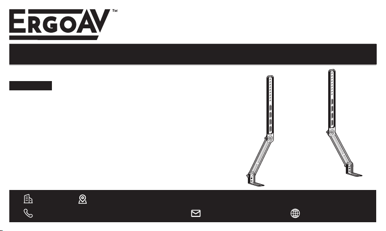
Universal Soundbar Mount Instruction Manual
Thank you for choosing ErgoAV!
(877) 419-7832 Mon-Fri 8am - 8pm (CST)
support@ergoav.com www.ergoav.com
9501 Louisiana Ave N, #200, Brooklyn Park, MN 55445
ErgoAV
English: 03-26
Français : 27 à 50
Español: 51 a 74

IMPORTANT SAFETY INFORMATION
Weight Capacity
Do not exceed weight capacity.
• Check package contents against supplied parts and hardware list to ensure that all parts were
received and undamaged. DO NOT use damaged or defective parts. If you require replacement parts,
please call technical support or email customer service.
• Carefully read all instructions before attempting installation. If you DO NOT understand the
instructions or if you have any questions or concerns, please call technical support or email customer
service.
• DO NOT use this product for any purpose that is not explicitly specified in this manual. DO NOT exceed
weight capacity. We are not liable for damage or injury caused by improper mounting, incorrect
assembly or inappropriate use.
• This speaker mount is only designed to be installed on the back of a compatible TV.
WARNING: When attaching to a TV wall mount, the wall must be capable of supporting five times the
weight of your TV, TV mount, and soundbar combined.
15 lbs
(6.8kg)
03
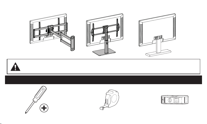
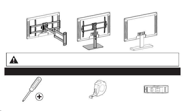
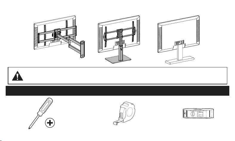
When attaching to a TV mount, TV stand or TV monitor, check the weight capacity of your TV mount,
TV stand and/or whether the original TV legs can support the extra weight.
Tools Needed (Not Included)
Phillips Screwdriver
TV Mount TV MonitorTV Stand
LevelTape Measure
04
02
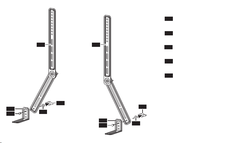
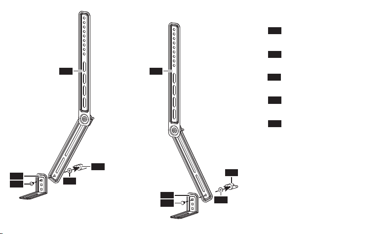
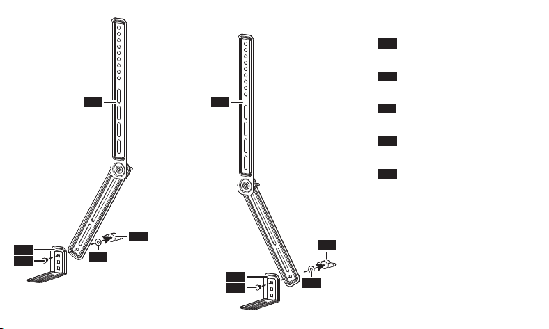
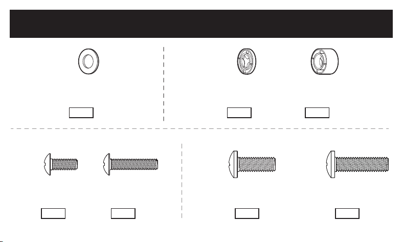
Knob
A1
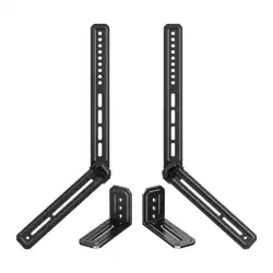
Speaker Bracket
01
Adjustable Bracket
A2
Bolt
B
Washer
B
01 01
A1
02
A2
02
A2
B
A1
05
Supplied Parts and Hardware for Step 1
INSTALLATION
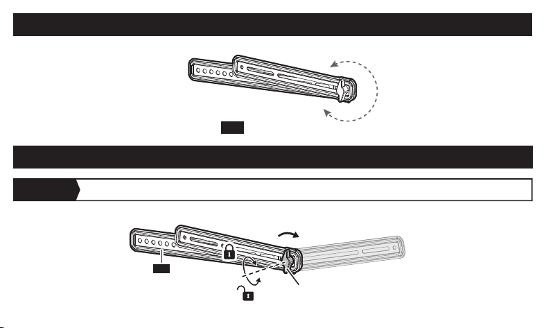
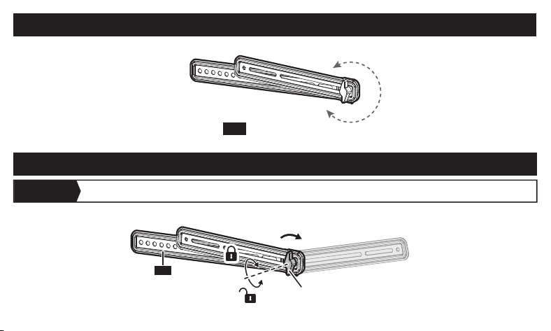
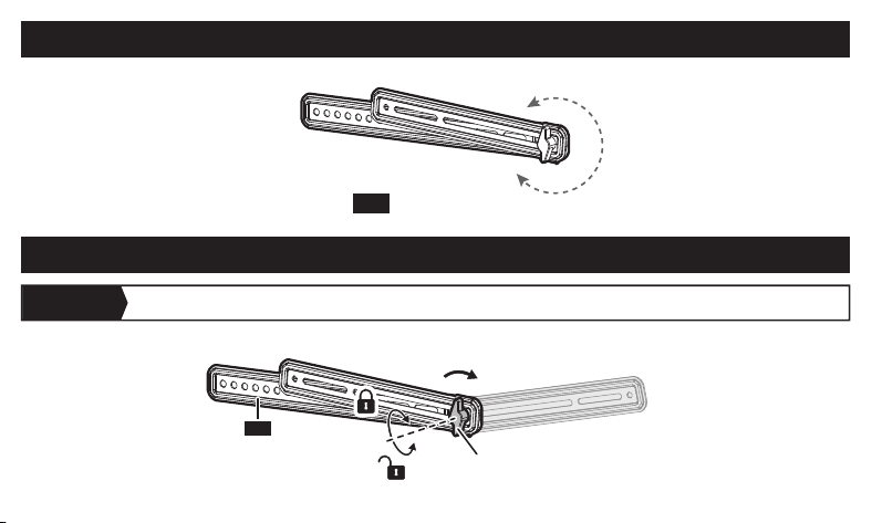
STEP 1 Unfold the Adjustable Bracket
Slightly loosen the knob [S] and unfold the bracket to the proper position. Retighten the knob to lock it.
SS
01
Adjustable Bracket
01 x 2
360°
06
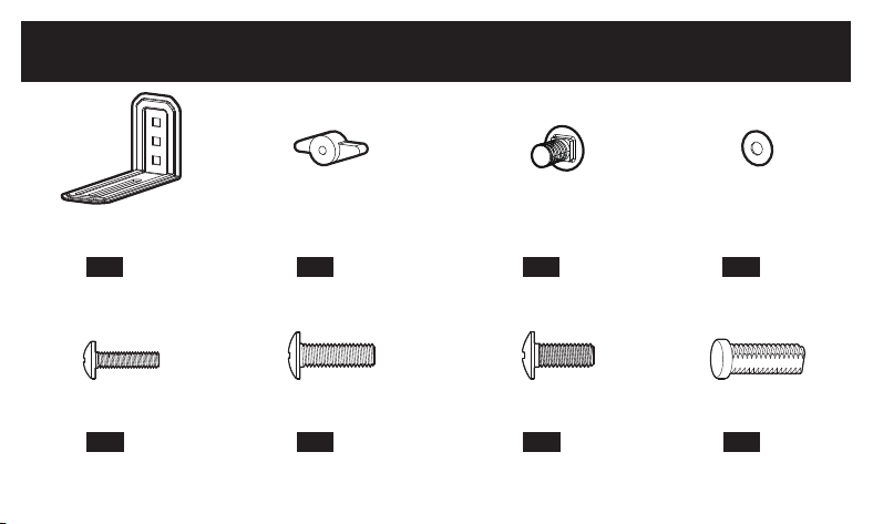
Speaker Bracket
02 x 2
D6
Washer
B x 4
M6 x 12mm
Bolt
A2 x 2
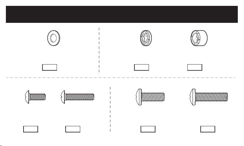
C x 2 D x 2 E x 2 F x 2
Knob
A1 x 2
M5 x 16mm
Bolt
M6 x 16mm
Bolt
M4 x 16mm
Bolt
Key Hole
Bolt
Supplied Parts and Hardware for Step 2
Not all hardware included in this package will be used.
07
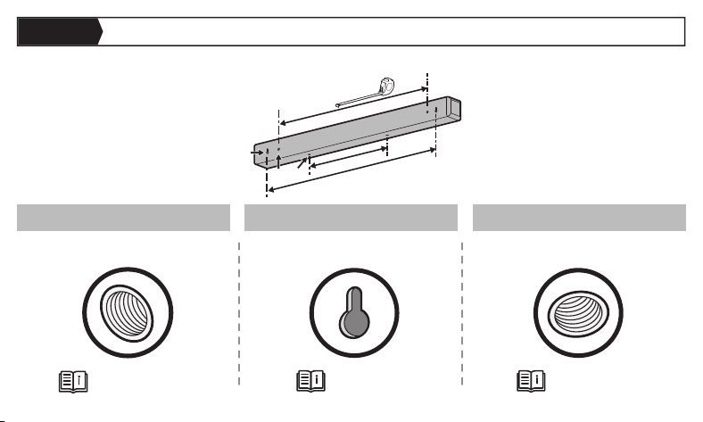
Option A Option B Option C
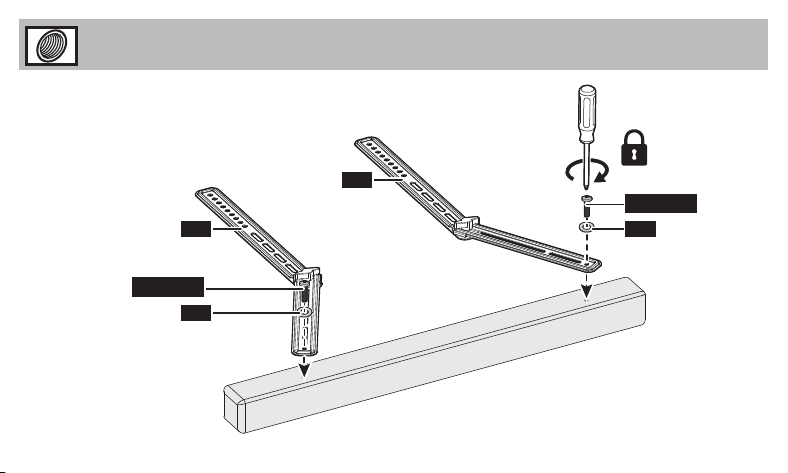
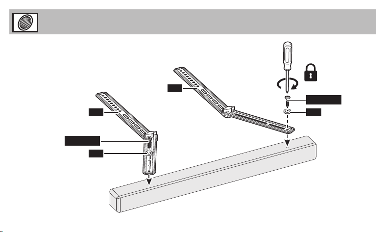
Speaker with Threaded Holes on
Back
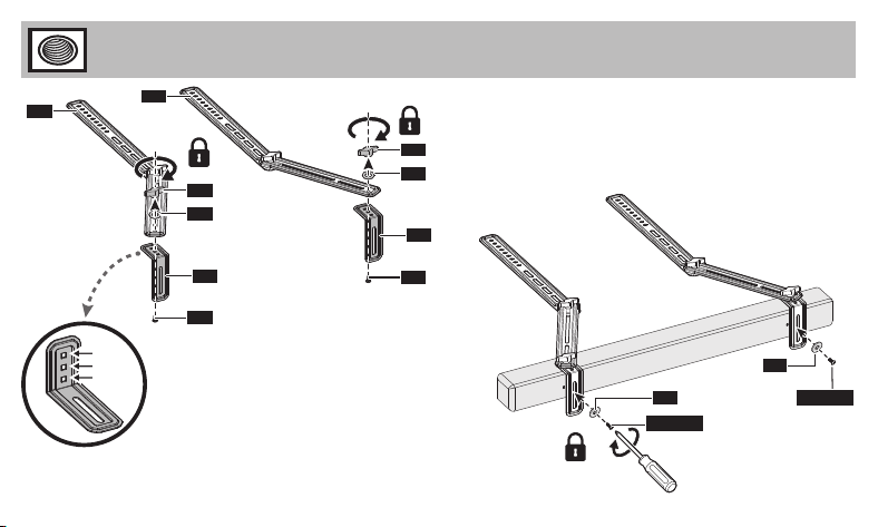
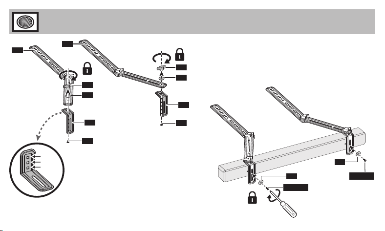
Speaker with Threaded Holes on
Bottom
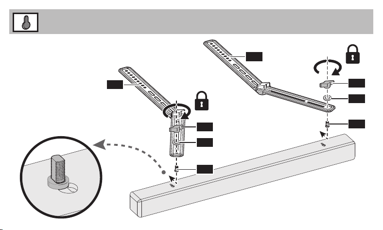
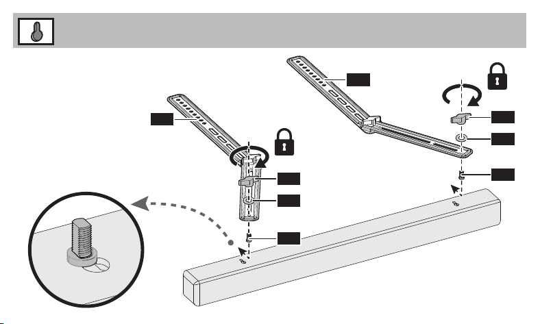
Speaker with Keyhole Slots
Page 11
Page 12
Page 13
STEP 2 Attach the Soundbar
2-1 Measure the distance between the mounting holes for easier installation of the adjustable brackets.
NOT Included
BB
A
C
08
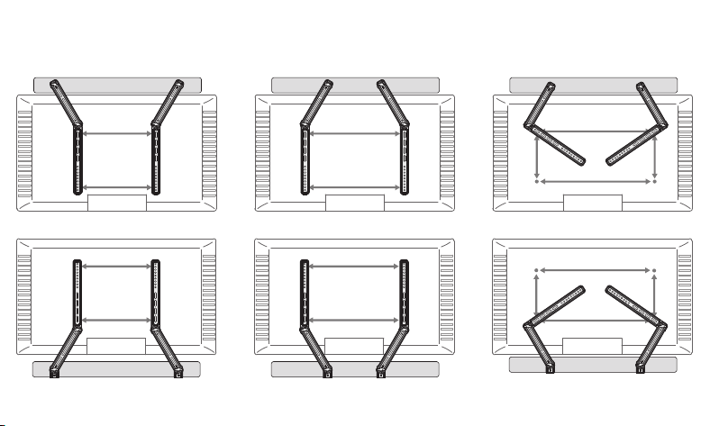
2-2 Choose the proper bracket configuration according to your measurements and TV mount type.
For TV Wall Mount:
09
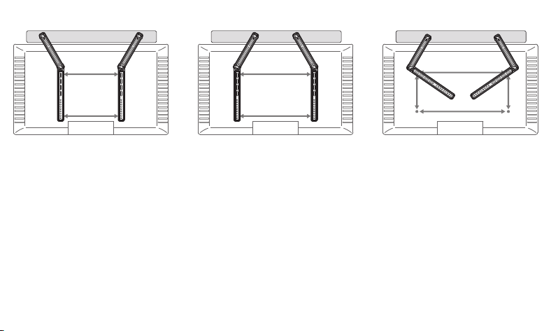
For TV Back or Tabletop TV Stand:
10
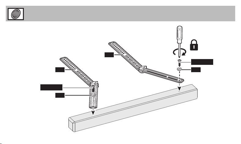
Option A Speaker with Threaded Holes on Back
01
B
01
C
|
D
| E
B
C
|
D
| E
11
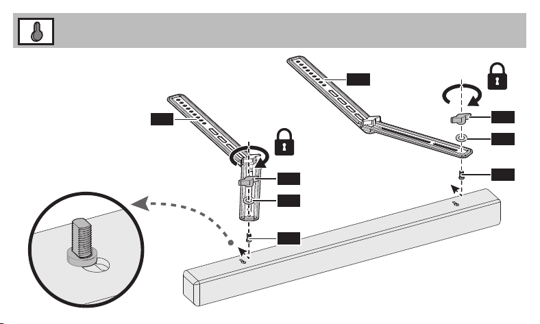
Option B Speaker with Keyhole Slots
01
B
F
A1
B
F
A1
01
12
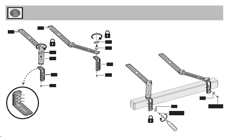
Option C Speaker with Threaded Holes on Bottom
01
01
02
B
A2
A1
02
B
A2
A1
B
C
|
D
| E
B
C
|
D
| E
13
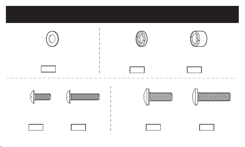
M6 M8
M6/M8
Washer
M-A x 4
M-C1 x 4 M-D1 x 4 M-D2 x 4
M-C2 x 4
M-B1 x 4
M-B2 x 4
L2.5mm
Spacer
L10mm
Spacer
M8 x 20mm
TV Bolt
M8 x 30mm
TV Bolt
M6 x 15mm
TV Bolt
M6 x 25mm
TV Bolt
Supplied Parts and Hardware for Step 3
Not all hardware included in this package will be used.
14
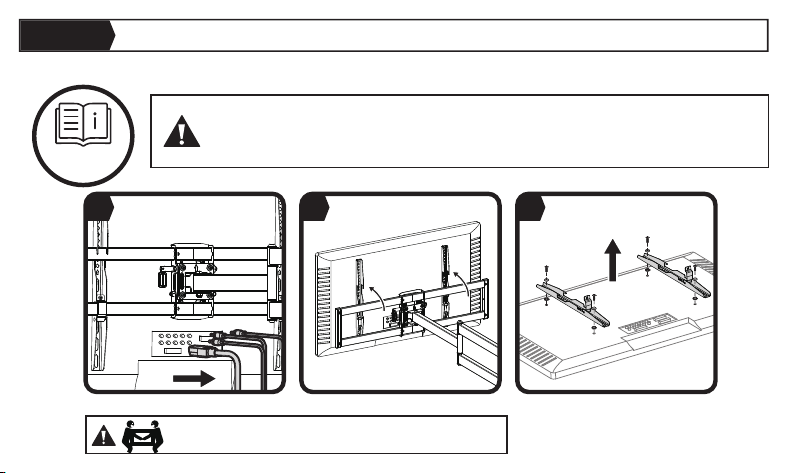
NOTE: Follow your TV wall mount's manual to properly remove your TV. Your TV
wall mount may vary from the illustrations below, but the steps for soundbar
installation should remain the same.
TV Mount
Manual
1 32
HEAVY! You may need assistance with this step.
STEP 3 Attach the Soundbar to TV
3-1 Prepare your TV [If mounted]
15
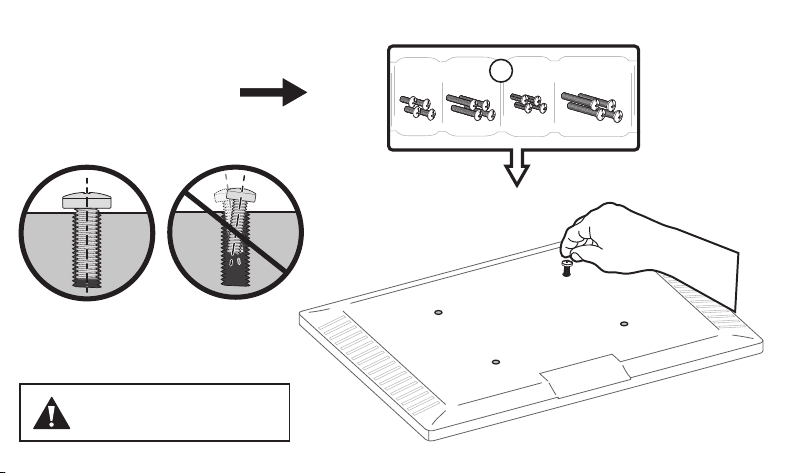
3-2 Select TV Bolts
Save the bolts that
fit (M6, or M8) for Step 3-3.
The correct bolt diameter
will thread smoothly into
your TV.
M6M6 M8M8
OR
The depth of the top and
bottom holes may differ.
16
For Flat-Back TV, go to Option A on page 19.
For Bump, Curved TV, Recessed Holes and Cables, go to Option B on page 20-21.
Too Short Too Long
WARNING:
• DO NOT turn the bolt past the bottom of the hole.
• If the bolt is too short, it may not adequately support the TV.
• If the bolt is too long, it could damage the TV.
• At least 4–5 turns into the threading is required.
• The depth of the bottom holes may be different from the top holes.
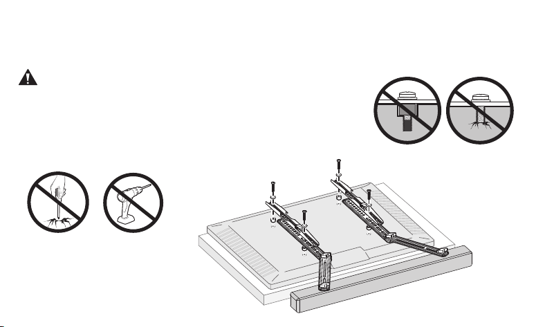
3-3 Secure the TV Brackets and Soundbar Brackets
D
O
N
O
T
o
v
e
r
t
i
g
h
t
e
n
17
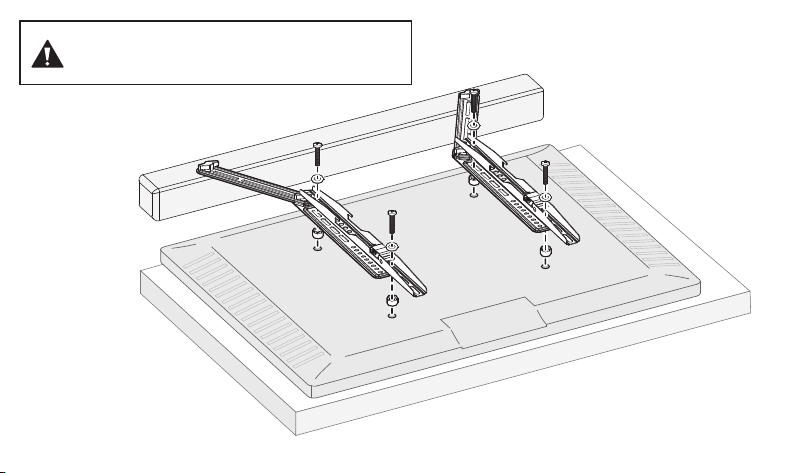
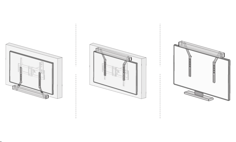
NOTE: The soundbar should be installed above
the TV when used with a tabletop TV stand or TV
monitor.
18
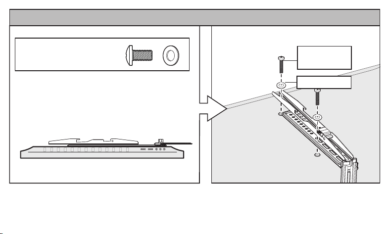
Washer M-A
Flat-Back TV
Use short TV bolts with
washers.
Option A
TV Bolt
M-C1
| M-
D1
19
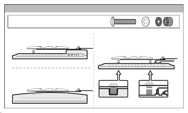
TV with Mounting Restrictions
Bump
Recessed Holes Protruding Cables
Curved TV
Use long TV bolts with washers and spacers to
create extra space between the TV and brackets.
Option B
20
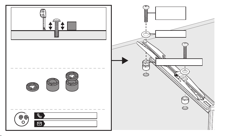
Note:
There are many possible spacer combinations
that can be used.
You can use a tape measure to measure the
protruding bolts or hold spacers next to them to
choose the right spacer combination.
OROR
Measure
Compare
Washer M-A
(877) 419-7832
support@ergoav.com
Spacer M-B1 | M-B2
TV Bolt
M-C2
| M-
D2
21
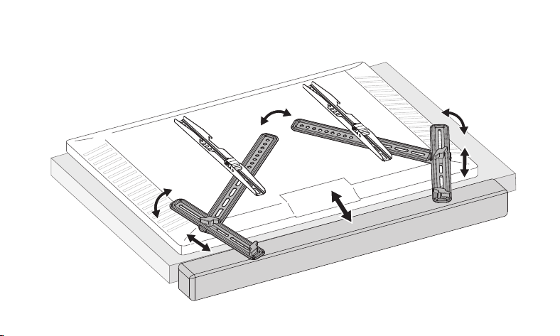
3-4 If needed, adjust the soundbar brackets to the desired position before hanging.
22
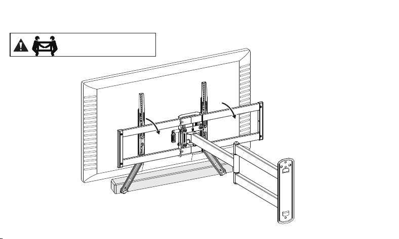
HEAVY! You may need
assistance with this step.
3-5
23
OROR
OR
OR
24
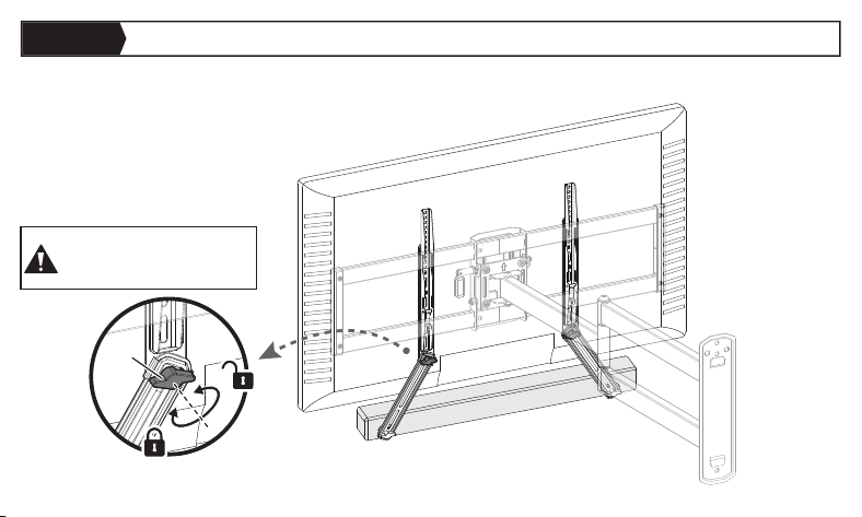
STEP 4 Adjust the Soundbar Brackets
Slightly loosen the knobs [S], then adjust the bracket to the desired position. Retighten
the knobs to lock it.
SS
25
Note: Please DO NOT
overtighten or
overloosen the knobs [S].
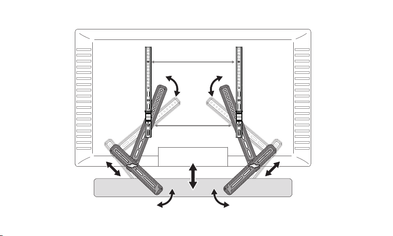
TIP: You can adjust the soundbar to make it closer to the bottom of the TV.
26
INFORMATIONS DE SÉCURITÉ IMPORTANTES
Capacité de poids
Ne pas dépasser la capacité de poids.
• Vérifiez le contenu du colis par rapport à la liste des pièces et du matériel fournis pour vous assurer que
toutes les pièces ont été reçues et non endommagées. NE PAS utiliser de pièces endommagées ou
défectueuses. Si vous avez besoin de pièces de rechange, veuillez appeler le support technique ou
envoyer un e-mail au service client.
• Lisez attentivement toutes les instructions avant de tenter l'installation. Si vous NE COMPRENEZ PAS
les instructions ou si vous avez des questions ou des préoccupations, veuillez appeler le support
technique ou envoyer un e-mail au service client.
• NE PAS utiliser ce produit à des fins qui ne sont pas explicitement spécifiées dans ce manuel. NE PAS
dépasser la capacité de poids. Nous ne sommes pas responsables des dommages ou des blessures
causés par un montage incorrect, un assemblage incorrect ou une utilisation inappropriée.
• Ce support de haut-parleur est uniquement conçu pour être installé à l'arrière d'un téléviseur
compatible.
AVERTISSEMENT : Lors de la fixation à un support mural de téléviseur, le mur doit être capable de
supporter cinq fois le poids de votre téléviseur, du support de télévision et de la barre de son combinés.
15 livres
(6.8kg)
27
Lors de la fixation à un support TV, un meuble TV ou un moniteur TV, vérifiez la capacité de poids de
votre support TV, meuble TV et/ou si les pieds TV d'origine peuvent supporter le poids supplémentaire.
Outils nécessaires (non inclus)
Tournevis Phillips
Support mural TV
Moniteur TV
Support TV
NiveauMètre à ruban
28
02
Bouton
A1
Support de haut-parleur
01
Support réglable
A2
Boulon
B
Rondelle
29
B
01 01
A1
02
A2
02
A2
B
A1
Pièces et matériel fournis pour l'étape 1
INSTALLATION
ÉTAPE 1
Dépliez le support réglable
Dévissez légèrement le bouton [S] et dépliez le support dans la position appropriée. Resserrer le bouton
pour le verrouiller.
S
S
01
Support réglable
01 x 2
360°
30
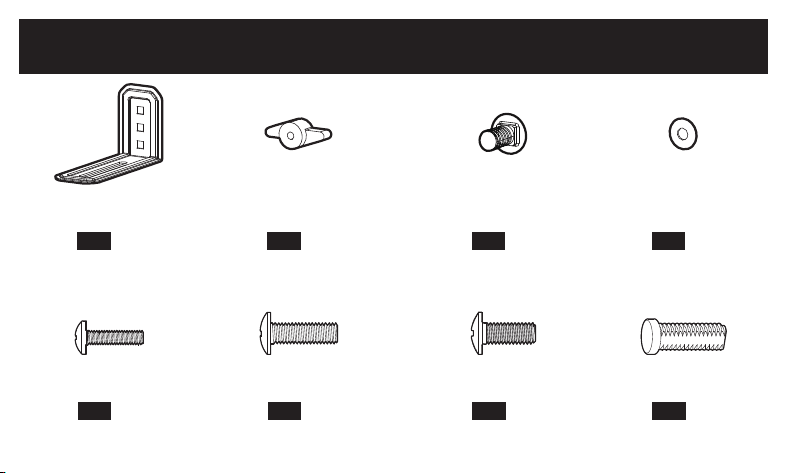
Support de haut-parleur
02 x 2
D6
Rondelle
B x 4
M6 x 12mm
Boulon
A2 x 2
C x 2
D x 2
E x 2
F x 2
Bouton
A1 x 2
M5 x 16mm
Boulon
M6 x 16mm
Boulon
M4 x 16mm
Boulon Boulon en forme de clé
Pièces et matériel fournis pour l'étape 2
Tous les accessoires inclus dans ce colis ne seront pas utilisés.
31
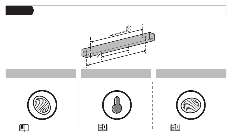
Option A
Option B
Option C
Haut-parleur avec trous filetés à
l'arrière
Haut-parleur avec trous filetés au
bas
Haut-parleur avec fentes en clé
Page 35
Page 36
Page 37
ÉTAPE 2
Fixez la barre de son
2-1 Mesurez la distance entre les trous de montage pour faciliter l'installation des supports réglables.
NON inclus
B
B
A
C
32
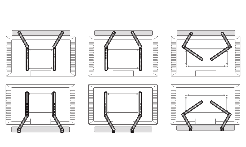
2-2 Choisissez la configuration de support appropriée en fonction de vos mesures et du type de montage de
télévision.
Pour montage mural de télévision :
33
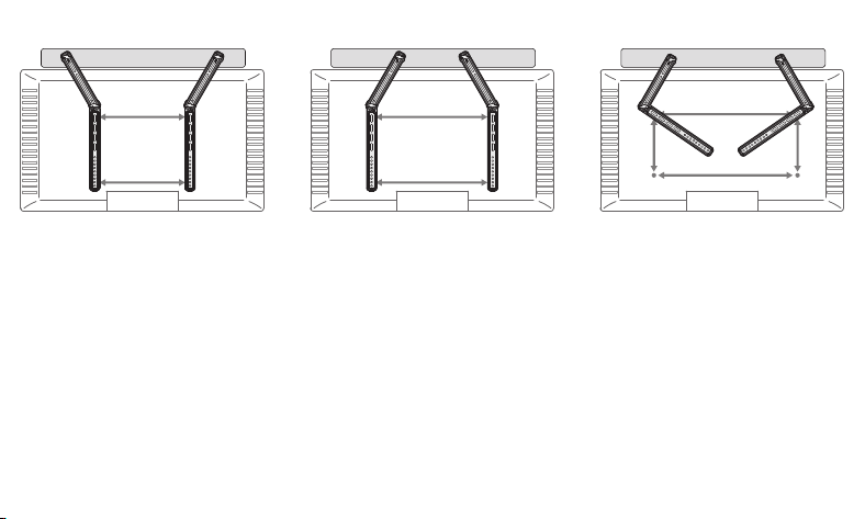
Pour le dos de la télévision ou le support de table :
34
Option A Haut-parleur avec trous filetés à l'arrière
01
B
01
C | D | E
B
C | D | E
35
Option B Haut-parleur avec fentes en forme de clé
01
B
F
A1
B
F
A1
01
36
Option C Haut-parleur avec trous filetés au fond
01
01
02
B
A2
A1
02
B
A2
A1
B
C
|
D
| E
B
C
|
D
| E
37
M6
M8
M6/M8
Rondelle
M-A x 4
M-C1 x 4 M-D1
x 4
M-D2
x 4
M-C2 x 4
M-B1 x 4 M-B2 x 4
L2.5mm
Entretoise
L10mm
Entretoise
M8 x 20mm
Boulon de téléviseur
M8 x 30mm
Boulon de téléviseur
M6 x 15mm
Boulon de
téléviseur
M6 x 25mm
Boulon de
téléviseur
Pièces et matériel fournis pour l'étape 3
Tous les accessoires inclus dans ce colis ne seront pas utilisés.
38
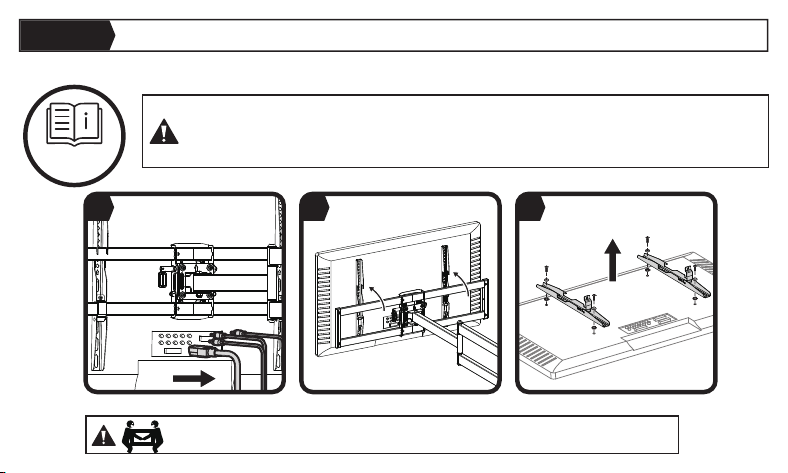
REMARQUE : Suivez le manuel de votre support mural TV pour retirer correctement
votre TV. Votre support mural TV peut varier par rapport aux illustrations ci-dessous,
mais les étapes pour l'installation de la barre de son devraient rester les mêmes.
Support TV
Manuel
1
3
2
LOURD ! Vous pourriez avoir besoin d'une assistance pour cette étape.
ÉTAPE 3
Fixez la barre de son au téléviseur
3-1 Préparez votre téléviseur [Si monté]
39
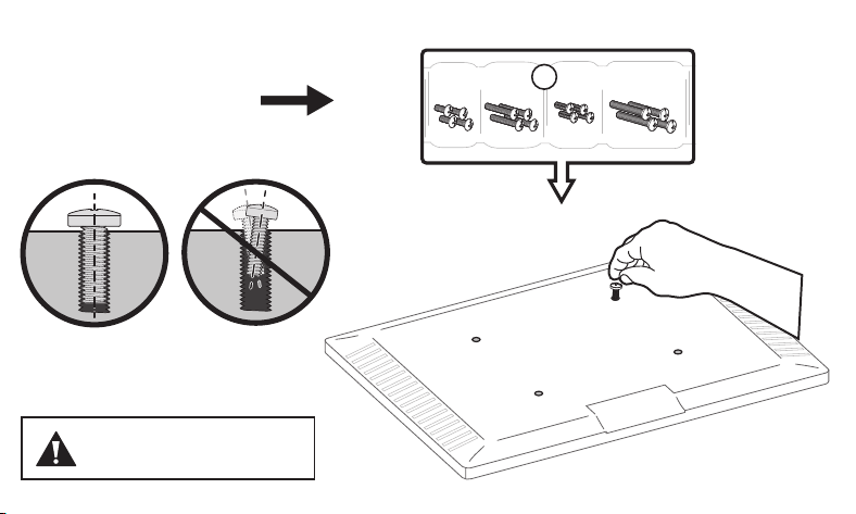
3-2 Sélectionner les boulons TV
Conservez les boulons qui conviennent
(M6 ou M8) pour l'étape 3-3.
Le diamètre de boulon correct
s'enfilera facilement dans
votre TV.
M6
M6
M8
M8
OU
La profondeur des trous du
haut et du bas peut différer.
40
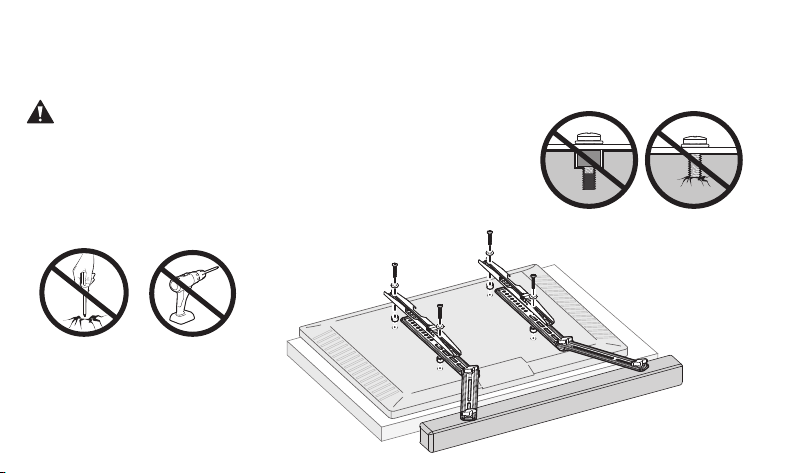
Pour TV à dos plat, allez à l'option A à la page 43.
Pour TV à renflement, TV courbé, trous encastrés et câbles, allez à l'option B à la page 44-45.
Trop court
Trop long
AVERTISSEMENT :
• NE PAS tourner le boulon au-delà du fond du trou.
• Si le boulon est trop court, il peut ne pas supporter correctement la TV.
• Si le boulon est trop long, cela pourrait endommager la TV.
• Au moins 4 à 5 tours dans le filetage sont nécessaires.
• La profondeur des trous du bas peut être différente de celle des trous du haut.
3-3 Sécuriser les supports TV et les supports de barre de son
N
E
P
A
S
t
r
o
p
s
e
r
r
e
r
41
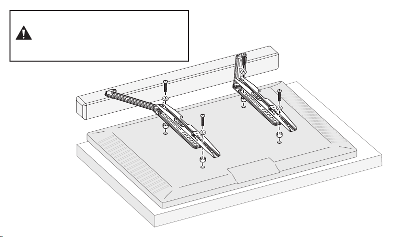
REMARQUE : La barre de son doit être
installée au-dessus du téléviseur
lorsqu'elle est utilisée avec un support de
table ou un moniteur TV.
42
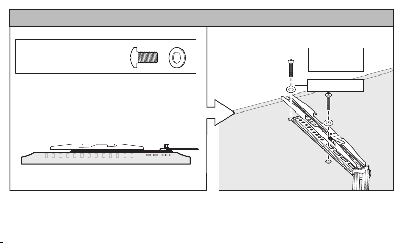
Rondelle M-A
TV à dos plat
Utilisez des boulons TV
courts avec des rondelles.
Option A
Boulon TV
M-C1 | M-D1
43
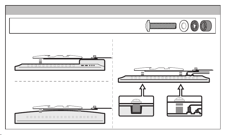
TV avec restrictions de montage
Renflement
Trous encastrés
Câbles saillants
TV courbe
Utilisez des boulons TV longs avec des rondelles et des entretoises
pour créer un espace supplémentaire entre la TV et les supports.
Option B
44
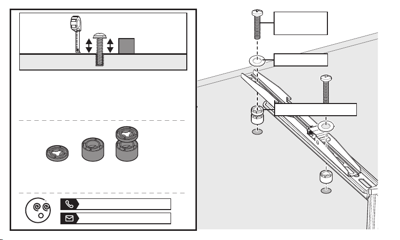
Remarque :
Il existe de nombreuses combinaisons possibles
d'entretoises qui peuvent être utilisées.
Vous pouvez utiliser un mètre à ruban pour
mesurer les boulons saillants ou tenir des
entretoises à côté d'eux pour choisir la bonne
combinaison d'entretoises.
OU
OU
Mesurer
Comparer
(877) 419-7832
support@ergoav.com
45
Rondelle M-A
Espaceur M-B1 | M-B2
TV Bolt
M-C2 | M-D2
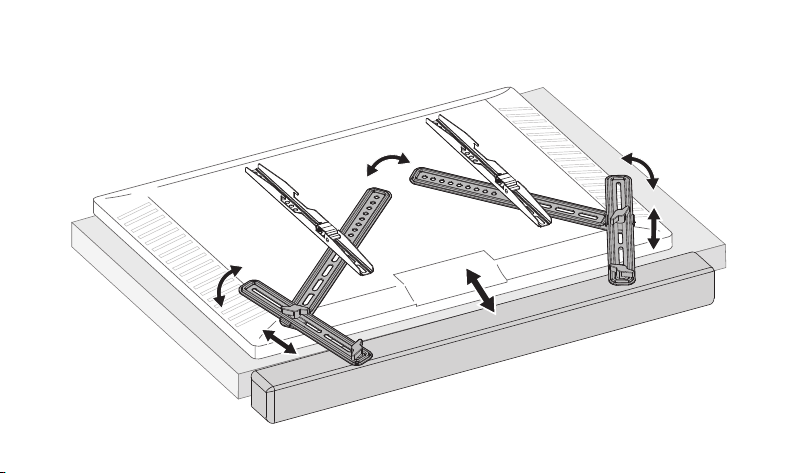
3-4 Si nécessaire, ajustez les supports de la barre de son à la position
souhaitée avant de suspendre.
46
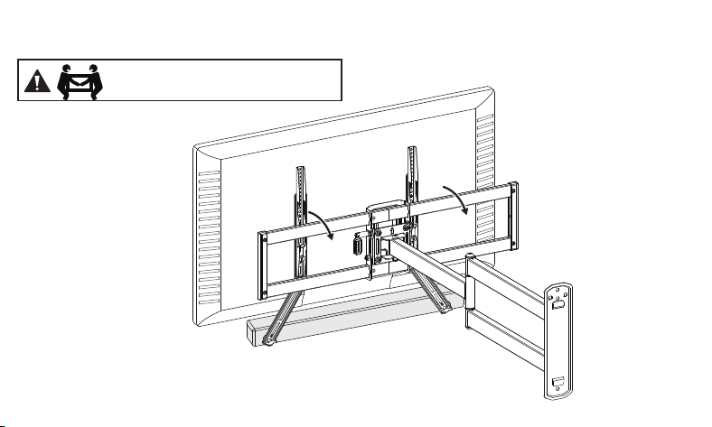
LOURD ! Vous pourriez avoir besoin
d'une assistance pour cette étape.
3-5
47
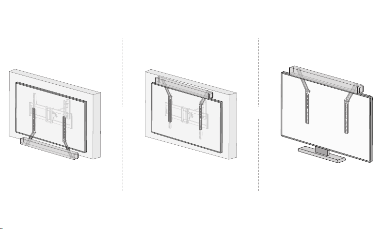
OU
OU
OU
OU
48
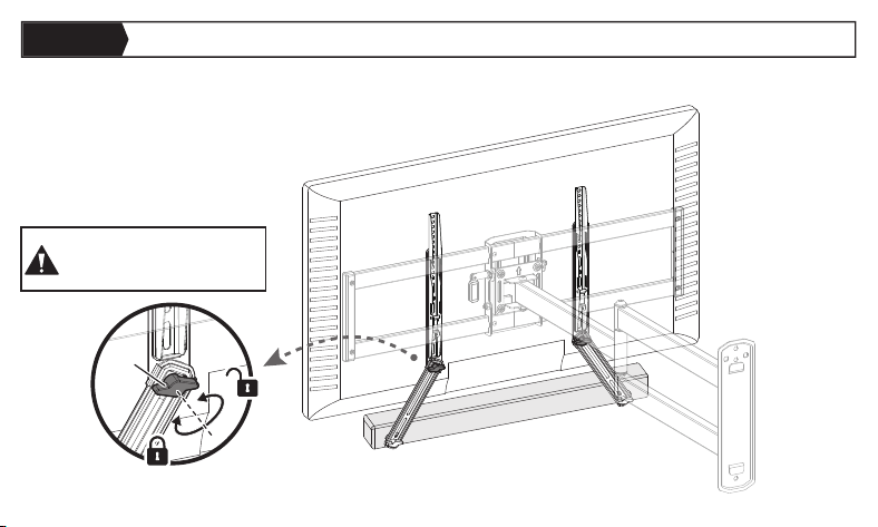
ÉTAPE 4
Ajustez les Supports de la Barre de Son
Desserrez légèrement le bouton [S], puis ajustez le support à la position souhaitée.
Reserrez le bouton pour le verrouiller.
S
S
49
Remarque : Veuillez NE
PAS trop serrer ni
desserrer les boutons [S].
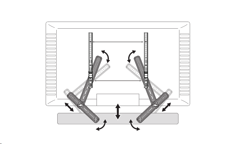
CONSEIL : Vous pouvez ajuster la barre de son pour la rapprocher du bas de la TV.
50
INFORMACIÓN DE SEGURIDAD IMPORTANTE
Capacidad de Peso
No exceda la capacidad de peso.
• Verifique el contenido del paquete con la lista de piezas y hardware proporcionados para asegurarse
de que todas las piezas fueron recibidas y no están dañadas. NO utilice piezas dañadas o defectuosas.
Si necesita piezas de repuesto, llame al soporte técnico o envíe un correo electrónico al servicio al
cliente.
• Lea cuidadosamente todas las instrucciones antes de intentar la instalación. Si NO entiende las
instrucciones o si tiene alguna pregunta o inquietud, llame al soporte técnico o envíe un correo
electrónico al servicio al cliente.
• NO utilice este producto para ningún propósito que no esté explícitamente especificado en este
manual. NO exceda la capacidad de peso. No somos responsables de daños o lesiones causadas por
un montaje inadecuado, una ensamblaje incorrecta o un uso inapropiado.
• Este soporte de altavoz está diseñado solo para ser instalado en la parte posterior de un TV
compatible.
ADVERTENCIA: Al fijar a un soporte de pared para TV, la pared debe ser capaz de soportar cinco veces
el peso de su TV, soporte de TV y barra de sonido combinados.
15 libras
(6.8kg)
51
Al adjuntar a un soporte para TV, soporte de TV o monitor de TV, verifique la capacidad de peso de su
soporte para TV, soporte de TV y/o si las patas originales de la TV pueden soportar el peso adicional.
Herramientas Necesarias (No Incluidas)
Destornillador Phillips
Soporte de TV
Monitor de TV
Soporte para TV
NivelCinta Métrica
52
02
Perilla
A1
Soporte para Altavoz
01
Soporte Ajustable
A2
Tornillo
B
Arandela
53
B
01 01
A1
02
A2
02
A2
B
A1
Piezas y Hardware Proporcionados para el Paso 1
INSTALACIÓN
PASO 1
Despliegue el Soporte Ajustable
Afloje ligeramente la perilla [S] y despliegue el soporte a la posición adecuada. Vuelva a apretar la perilla
para bloquearlo.
S
S
01
Soporte Ajustable
01 x 2
360°
54
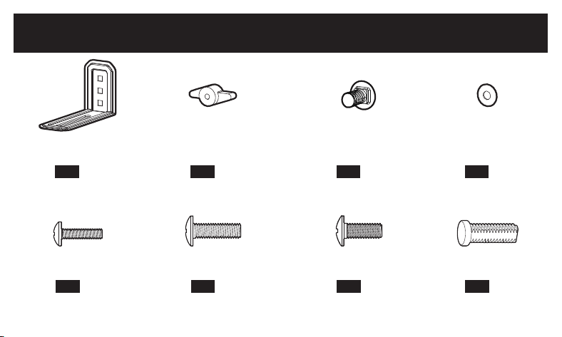
Soporte para Altavoz
02 x 2
D6
Arandela
B x 4
M6 x 12mm
Tornillo
A2 x 2
C x 2 D x 2 E x 2 F x 2
Perilla
A1 x 2
M5 x 16mm
Tornillo
M6 x 16mm
Tornillo
M4 x 16mm
Tornillo Tornillo de Ranura
Piezas y Hardware Suministrados para el Paso 2
No todo el hardware incluido en este paquete será utilizado.
55
Opción A
Opción B
Opción C
Altavoz con Agujeros Rosqueados
en la Parte Posterior
Altavoz con Agujeros Rosqueados
en la Parte Inferior
Altavoz con Ranuras de Llave
Página 59
Página 60
Página 61
PASO 2
Adjuntar la Barra de Sonido
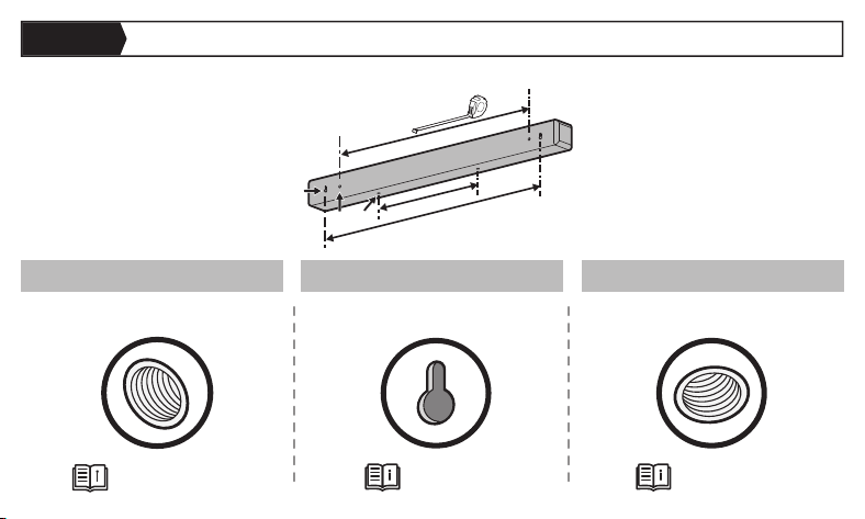
2-1 Mida la distancia entre los agujeros de montaje para facilitar la instalación de los soportes ajustables.
NO Incluido
B
B
A
C
56
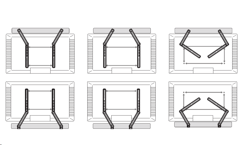
2-2 Elija la configuración de soporte adecuada según sus medidas y el tipo de montaje del televisor.
Para Montaje en Pared del Televisor:
57
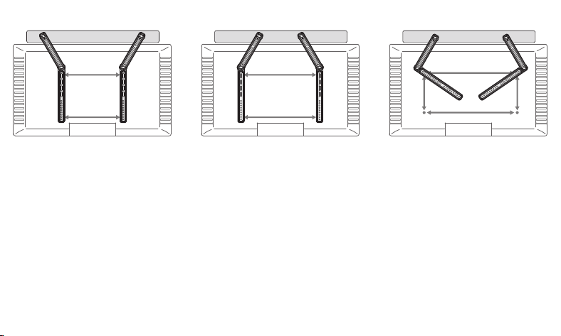
Para la Parte Trasera del Televisor o Soporte de Mesa para Televisor:
58
Opción A Altavoz con Agujeros Rosqueados en la Parte Posterior
01
B
01
C | D | E
B
C | D | E
59
Opción B Altavoz con Ranuras de Llave
01
B
F
A1
B
F
A1
01
60
01
01
02
B
A2
A1
02
B
A2
A1
B
C
|
D
| E
B
C
|
D
| E
Opción C Altavoz con Agujeros Rosqueados en la Parte Inferior
61
M6
M8
M6/M8
Arandela
M-A x 4
M-C1 x 4 M-D1 x 4
M-D2 x 4
M-C2 x 4
M-B1 x 4 M-B2 x 4
L2.5mm
Espaciador
L10mm
Espaciador
M8 x 20mm
Tornillo para TV
M8 x 30mm
Tornillo para TV
M6 x 15mm
Tornillo para TV
M6 x 25mm
Tornillo para TV
Piezas y Hardware Suministrados para el Paso 3
No todo el hardware incluido en este paquete será utilizado.
62
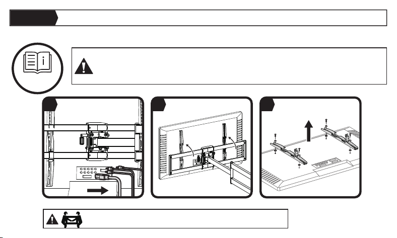
NOTA: Siga el manual de su soporte de pared para TV para quitar su TV correctamente.
Su soporte de pared para TV puede variar de las ilustraciones a continuación, pero los
pasos para la instalación de la barra de sonido deben permanecer iguales.
Soporte para
TV Manual
1
3
2
¡PESADO! Puede que necesite asistencia con este paso.
PASO 3
Adjunte la Barra de Sonido al Televisor
3-1 Prepare su TV [Si está montado]
63
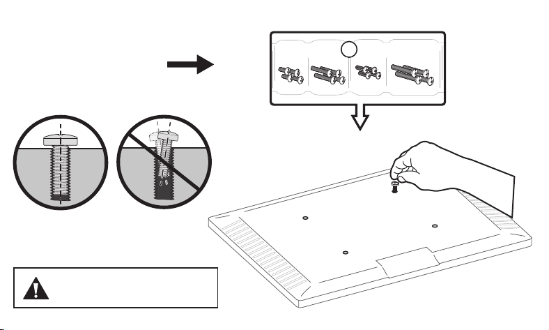
3-2 Seleccione Tornillos para TV
Guarde los tornillos que
encajen (M6 o M8) para el Paso 3-3.
El diámetro correcto del
tornillo se enroscará
suavemente en su TV.
M6
M6
M8
M8
O
La profundidad de los agujeros
superior e inferior puede diferir.
64
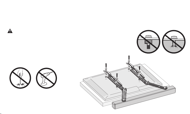
Para TV de Espalda Plana, dirígete a la Opción A en la página 67.
Para TV con Bultos, Curvadas, Agujeros Recesados y Cables, dirígete a la Opción B en la
página 68-69.
Demasiado
Corto
Demasiado
Largo
ADVERTENCIA:
• NO gire el tornillo más allá del fondo del agujero.
• Si el tornillo es demasiado corto, puede que no soporte adecuadamente la TV.
• Si el tornillo es demasiado largo, podría dañar la TV.
• Se requieren al menos 4–5 vueltas en la rosca.
• La profundidad de los agujeros inferiores puede ser diferente a la de los
agujeros superiores.
3-3 Asegure los Soportes de TV y los Soportes de la Barra de Sonido
N
O
a
p
r
i
e
t
e
d
e
m
a
s
i
a
d
o
65
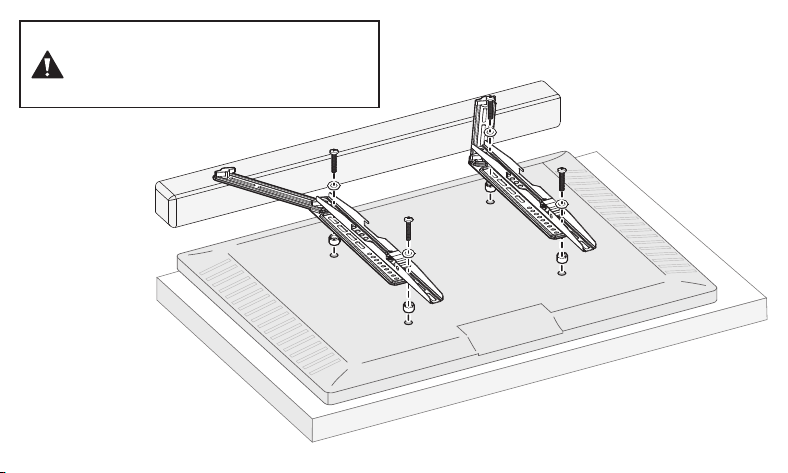
NOTA: La barra de sonido debe instalarse
encima del televisor cuando se use con un
soporte de mesa para TV o un monitor de
TV.
66
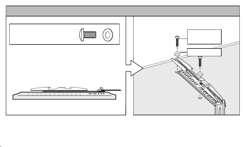
Arandela M-A
TV de Espalda Plana
Use tornillos cortos para
TV con arandelas.
Opción A
Tornillo para TV
M-C1 | M-D1
67
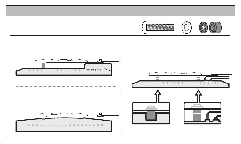
TV con Restricciones de Montaje
Bulto
Agujeros Recesados Cables Protruyentes
TV Curvada
Use tornillos largos para TV con arandelas y separadores
para crear espacio adicional entre la TV y los soportes.
Opción B
68
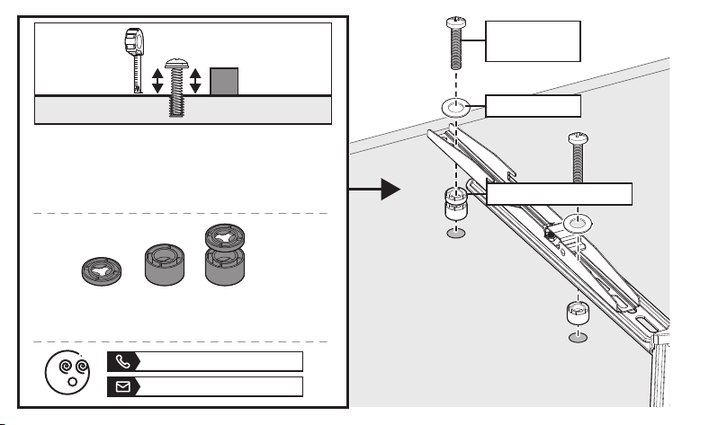
Arandela M-A
Separador M-B1/M-B2
Soporte de TV
M-C2 | M-D2
Nota:
Hay muchas combinaciones posibles de
separadores que se pueden usar.
Puede usar una cinta métrica para medir los
tornillos que sobresalen o sostener separa-
dores junto a ellos para elegir la combinación
de separadores correcta.
O
O
Medir
Comparar
(877) 419-7832
support@ergoav.com
69
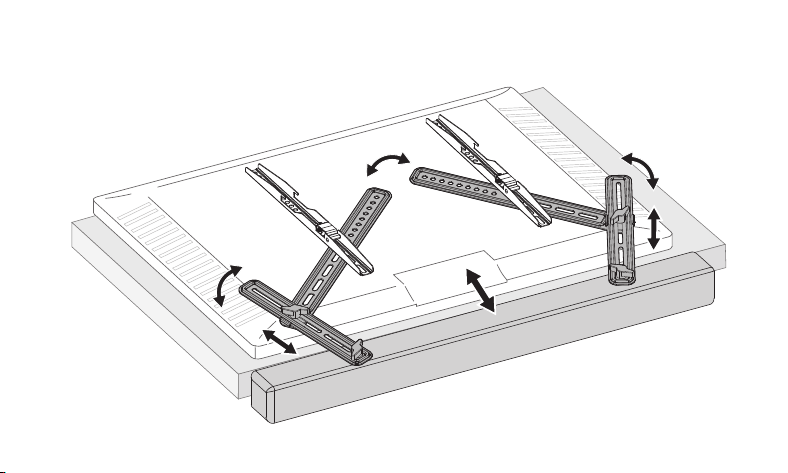
3-4 Si es necesario, ajuste los soportes de la barra de sonido a la posición
deseada antes de colgar.
70
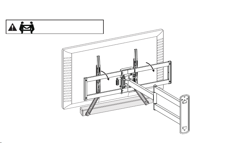
¡PESADO! Puede que necesite
asistencia con este paso.
3-5
71
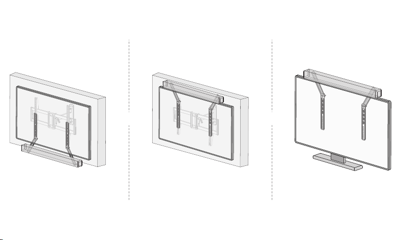
OO
O
O
72
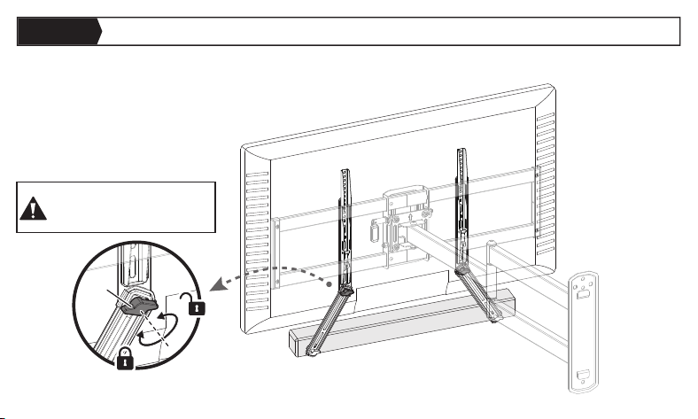
PASO 4
Ajuste los Soportes de la Barra de Sonido
Afloje ligeramente la perilla [S], luego ajuste el soporte a la posición deseada. Vuelva
a apretar la perilla para bloquearla.
S
S
73
Nota: Por favor, NO
apriete ni afloje
demasiado las perillas [S].
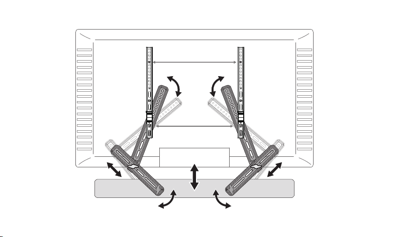
CONSEJO: Puede ajustar la barra de sonido para acercarla a la parte inferior de la TV.
74

Computer Monitor Mounts
Speaker Stands
TV Mounts
At ErgoAV, our goal is to provide the high-quality audio video solutions and product support
that you need. If you have any questions, concerns, or feedback, please let us know!
860-03126-00 Rev00
(877) 419-7832 Mon-Fri 8am - 8pm (CST) support@ergoav.com www.ergoav.com
9501 Louisiana Ave N, #200, Brooklyn Park, MN 55445ErgoAV