SKU: EX_2H
User Manual
LED 2 Head
Exit Sign
support@sunco.com
(844) 334-9938
Lighting made better.
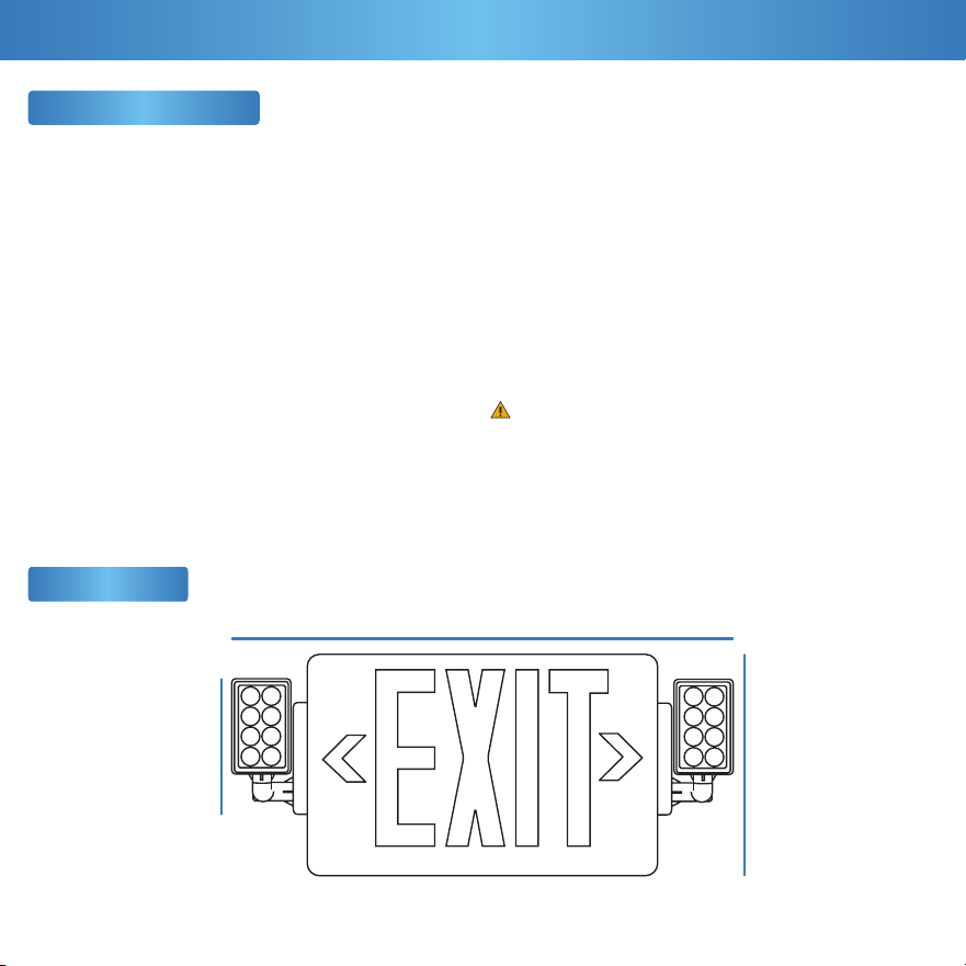
Exit Sign
1
Let there be light!
(literally)
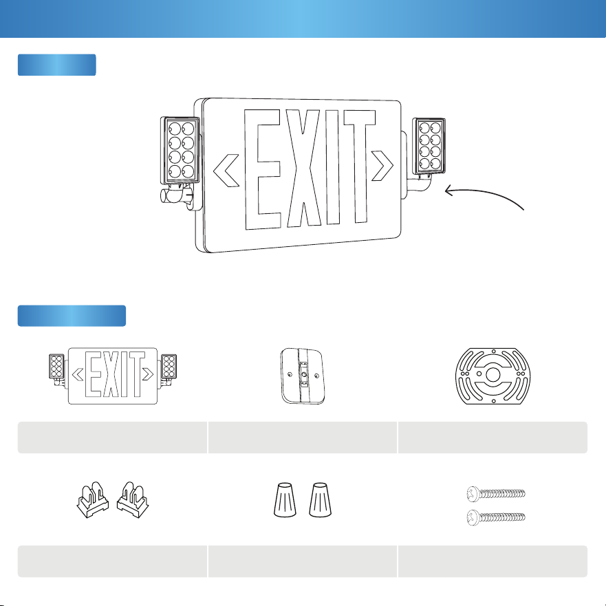
Components
x1
x2
x1
x2
Exit Sign Housing + Panel
Support Connectors
Canopy Mount
Wire Nuts
Mounting Bracket
Mounting Screws
x1
x2
What’s in the Box?
A B C
D E
F
2
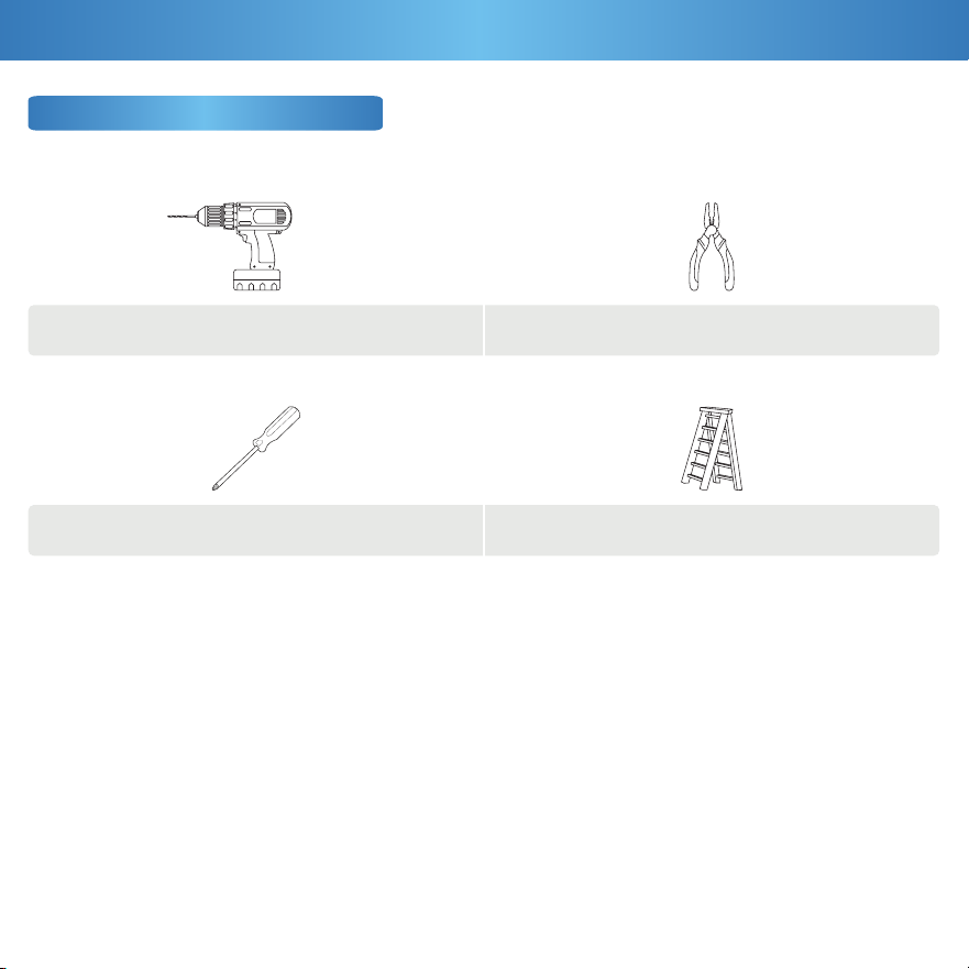
Ladder
Pliers
Drill
Screwdriver
Get Your Gear (Not Included)
IMPORTANT: Prior to exit sign installation, install the junction box into the ceiling or the wall.
The battery in this unit may not be fully charged upon unboxing. After electricity is hooked up to the unit, let the battery
charge for at least 24 hours. It is then ready for normal operation. Unused wires must be capped with a wire nut.
What You Need
• Turn o circuit breaker before installing this fixture.
• Suitable for use in damp environments at temperatures
ranging from 32°F to 104°F. Not for use where directly
exposed to water.
• Not compatible with photo controls.
• Not compatible with occupancy sensors.
• Not compatible with 3rd party sensors.
• Not compatible with dimmers.
• All electrical connections must be in accordance with local
and National Electric Code (N.E.C.) standards.
• Not compatible with timing devices.
• Please review installation manual carefully before
proceeding. Consult a qualified electrician if you are
unfamiliar with proper electrical wiring connections.
Product Size
3
16.3”
7.6”3.6”
Safety Information
Before You Start
This device complies with Part 15 of the FCC rules.
Operation is subject to the following two conditions:
1) This device may not cause harmful interference.
2) This device must accept any interference that may
cause undesired operation. Please review all
instructions carefully prior to installation.
WARNING:
Cancer & Reproductive Harm- www.P65Warnings.ca.gov
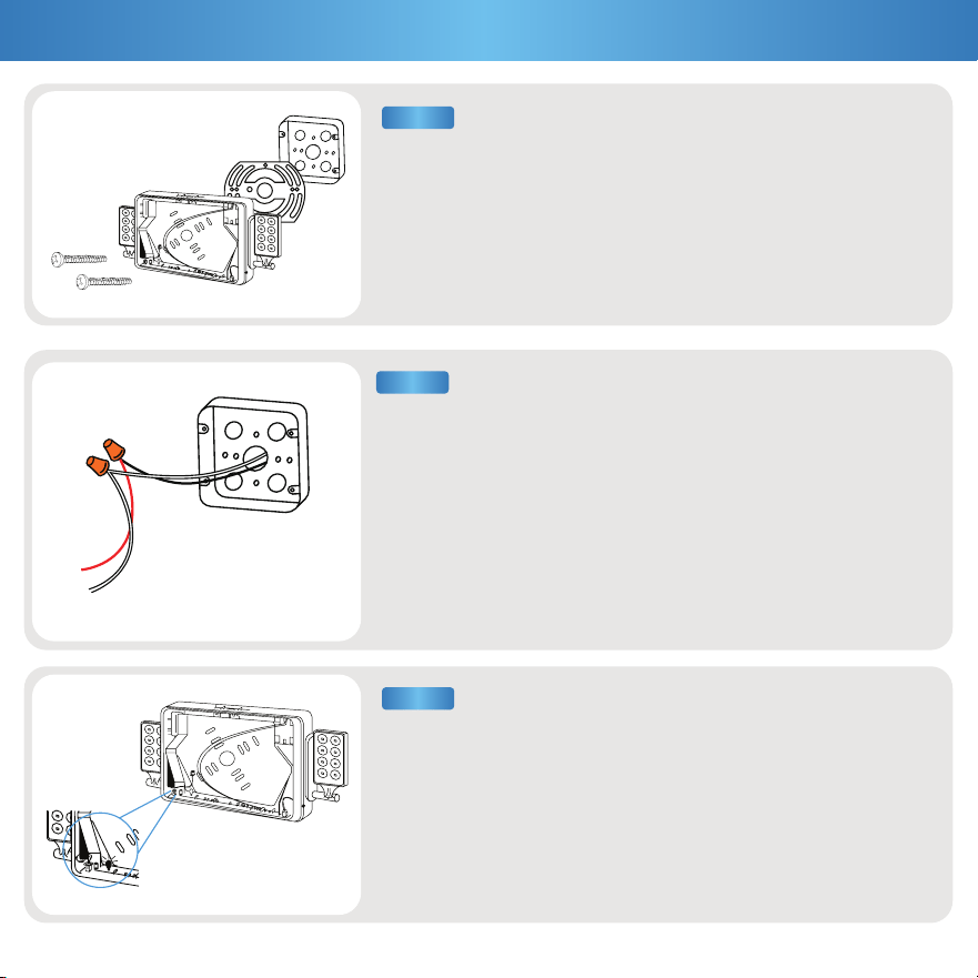
a. Remove the canopy mount (B) and the support connectors (D)
from the accessory bag.
b. Snap the two support connectors (D) into the canopy
mount (B) slots.
Note: This should not require a lot of force.
a. Turn off circuit breaker before installation.
b. Use a flathead screwdiver to pry open the exit sign housing.
Pull off the faceplate and set it aside.
c. Remove the mounting components and the accessory bag
from the housing and set them aside.
4
Installation Guide (Ceiling Mount)
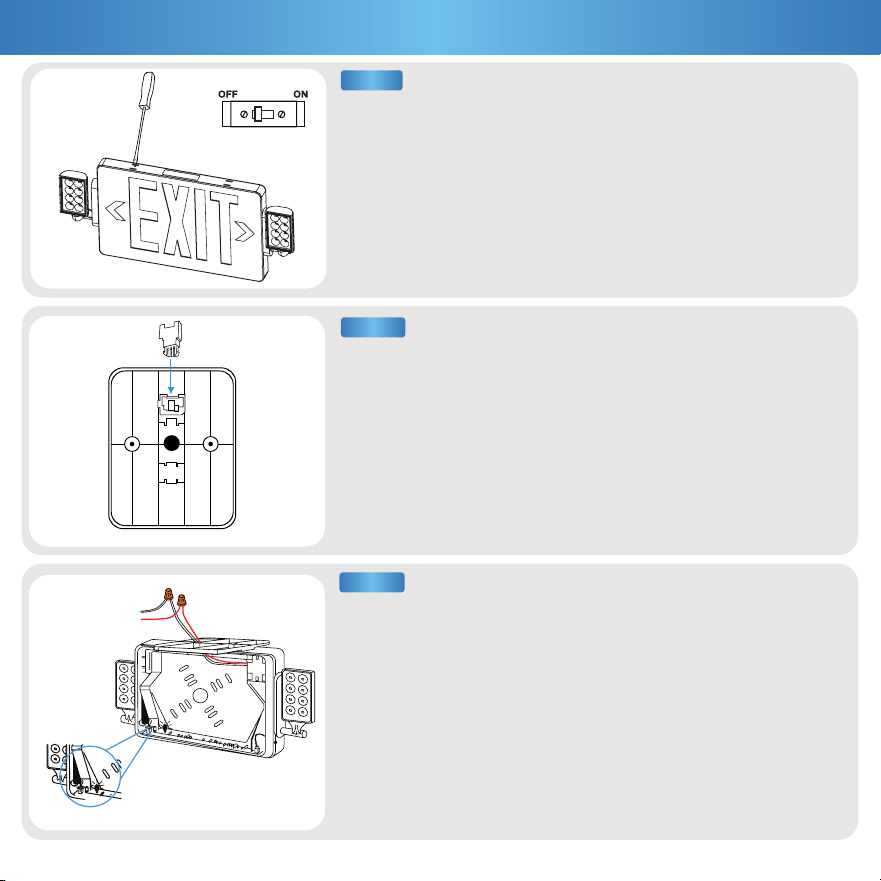
STEP 2
STEP 1
D
B
a. Feed the luminaire wires throught the canopy mount (B) and the
mounting bracket (C).
b. Connect the luminaire wires to the junction box supply wires using
the included wire nuts (E).
• Red to Black (Live) • White to White (Neutral)
• Ground wire can be connected to the mounting plate (C).
c. Connect the battery to the PC board by plugging the connector
into socket.
d. Feed excess wire into the junction box.
STEP 3
E
C
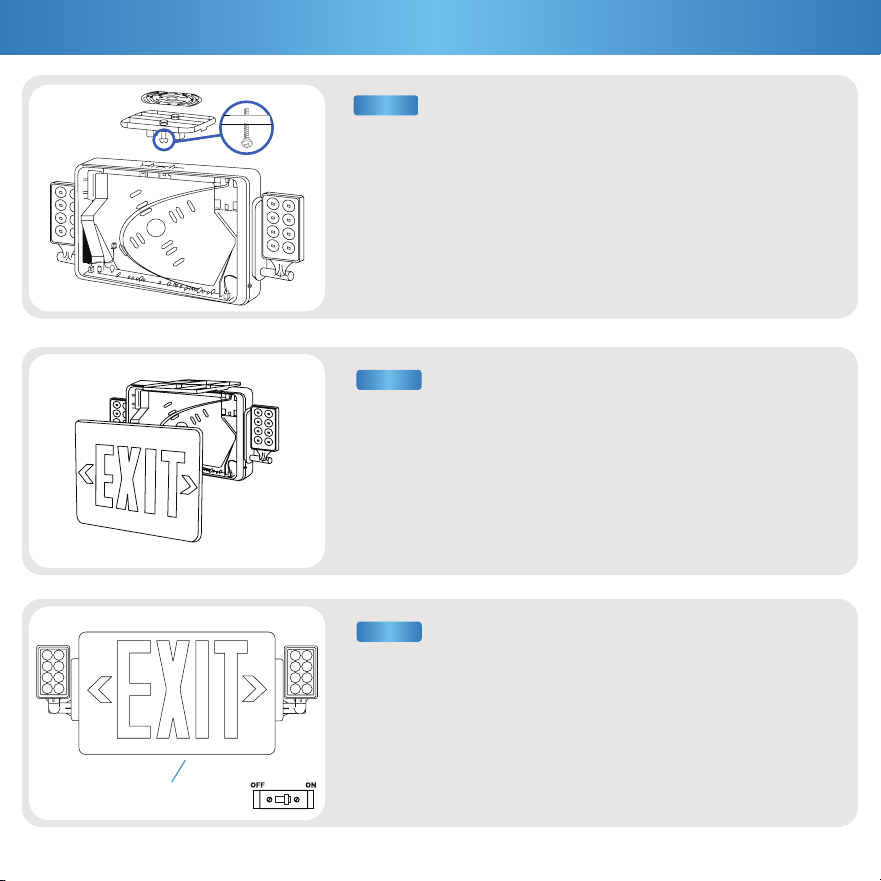
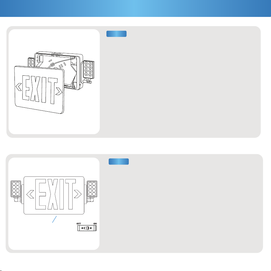
a. Reattach the faceplate. Ensure that all four corners are properly
snapped together.
b. Knock out directional arrow(s), as appropriate for your light
fixture location.
a. Turn on the circuit breaker and test the light.
b. Press the test button to confirm if exit sign is powered.
Note: Battery may need 24 hours to charge before light
fixture is used for emergency purposes.
5
STEP 5
STEP 6
Installation Guide (Cont.)
Test Button
a. Align the mounting bracket (C) to the screw holes of the canopy
mount (B), then screw the mounting scews (F) to secure in place.
b. Feed the luminaire wires throught the canopy mount (B) and the
mounting bracket (C).
STEP 4
C
F
B
a. Use the exit sign knockout holes as a reference to position the
exit sign to the junction box.
a. Drill holes for the knockouts on the backplate that correspond to
junction box holes.
6
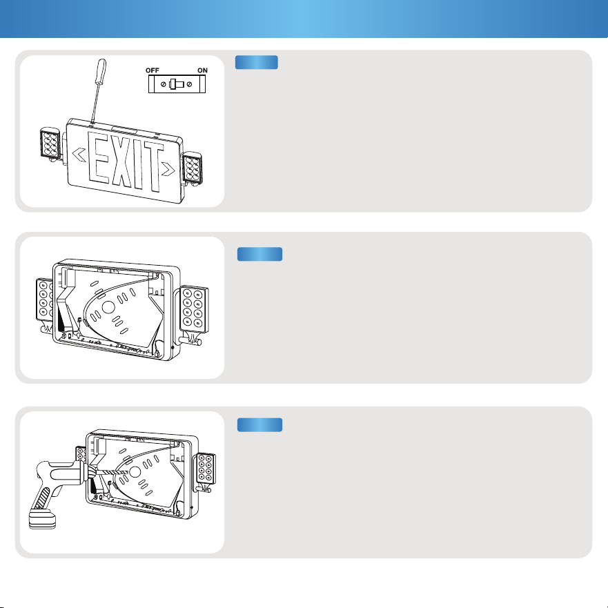
STEP 2
STEP 3
Installation Guide (Wall Mount)
a. Turn off circuit breaker before installation.
b. Use a flathead screwdiver to pry open the exit sign housing.
Pull off the faceplate and set it aside.
c. Remove the mounting components and the accessory bag
from the housing and set them aside.
STEP 1
a. Connect the battery to the PC board by plugging the connector
into socket.
c. Feed excess wire into the junction box.
STEP 6
STEP 5
Installation Guide (Cont.)
7
a. Use the mounting screws (F) to install the mounting
plate (C) to the junction box.
b. Feed the luminaire wires through the housing knockouts.
STEP 4
a. Connect the luminaire wires to the junction box supply wires using
the included wire nuts (E).
• Red to Black (Live) • White to White (Neutral)
• Ground wire can be connected to the mounting plate (C).
E
F
C
Installation Guide (Cont.)
8
a. Reattach the faceplate. Ensure that all four corners are properly
snapped together.
b. Knock out directional arrow(s), as appropriate for your light
fixture location.
a. Turn on the circuit breaker and test the light.
b. Press the test button to confirm if exit sign is powered.
Note: Battery may need 24 hours to charge before light
fixture is used for emergency purposes.
STEP 7
STEP 8
Test Button
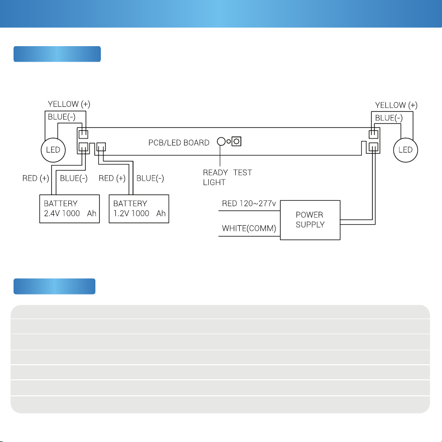
Voltage
Wattage
Power Factor
CRI
Weight
Housing Material
Dimmable
120 to 277 V
3.3W
0.48
80+
1.61 lbs
ABS + PMMA
No
120°
300 lm
IP20
3.6V 1000mah NI-MH
Battery
Damp Rated
3 Years
Beam Angle
Lumens
IP Rating
Battery
Power Source
Moisture Rating
Warranty
Wiring Diagram
9
Specifications
Product Details
m m
10
Common Troubleshooting
Feeling in the dark about an issue with your product? No
worries! Our troubleshooting section is here to shed some light
and provide you with easy-to-follow solutions for any problem.
Light unexpectedly fails.
Light not lasting on a single charge.
Fixture buzzing with appliances or electronic devices.
Look for nearby interferences that can cause buzzing.
Such as televisions, radios, computers, etc.
Battery is not charged.
Light flickering with other lights on the same circuit.
Check that the lights on the same circuit are not
overloading the circuit.
Light flickering when turned on.
Double check if fixture is properly connected
and circuit breaker hasn’t been tripped.
Verify the battery is securely plugged in and the supply
wires are properly connected.
Ensure the battery is properly connected.
Light isn’t turning on.
Test light is not working.
Fixture buzzing with power outages. Verify light is connected to surge protector securely.
For further assistance, reach out to customer support.
Light is flickering when turning on.
Check that fixture wiring connections are secure.
For further assistance, reach out to customer support.
Ensure the battery is properly connected and compatible.
If you still need some assistance, please feel free to
contact us with any questions. Our team of lighting experts
are happy to help brighten your day.
Battery
Flickering
Buzzing
Installation

support@sunco.com
(844) 334-9938
Lighting made better.
REV1.0