
SMALL APERTURE SERIES
SA68
INSTALLATION AND SUPPORT MANUAL
2
SMALL APERTURE SPEAKER
SA68
TABLE OF CONTENTS
2 Box Contents
2 Introduction
2 Important Safety Information
2 Assembling the Parts
3 Installing the Enclosure
4 Preparing the Enclosure Opening
4 Drywall | Gypsum Board Installation with
Sheetrock Trim
4 Solid Surface Installation with
Solid Surface Trim
5 Drywall | Solid Surface Installation with
Retro Fit Trim
5 Installing the Speaker Module
6 Trim Kit Options
7 Technical Specifications
8 Warranty
FRONT VIEW SIDE VIEW
BOX CONTENTS
(1) Quickstart Guide
(1) SA68-ENC Speaker Enclosure | 60597
(2) SA Mounting Brackets
(4) 8-32 x 1/2 Pan Head Machine Screws
(4) #8 Lock Washers
(4) #8 Flat Washers
(4) 6/32 Course Head Screws
(1) SA Space Saver Accessory Kit | 60610
• (1) 3” Round Space Saver
• (1) 4” Round Space Saver
• (1) 3” Square Space Saver
• (1) 4” Square Space Saver
INTRODUCTION
Thank you for selecting the SA68 James by Sonance
Small Aperture Series Speaker. Please take the time to
carefully read through the manual, study the illustrations
and system diagrams. This extra time can lead to
trouble-free operation and continued musical enjoyment.
IMPORTANT: Read this section in its entirety before
attempting use of the speaker.
IMPORTANT SAFETY INSTRUCTIONS
Always follow these basic safety precautions when using
your speaker to reduce the risk of fire, electric shock,
and injury to prople or objects.
1. Read all the safety and operating instructions before
operating the speaker and retain them for future
reference.
2. Adhere to all warnings and precautions listed on the
speaker and in the operating instructions.
3. Follow all operating instructions.
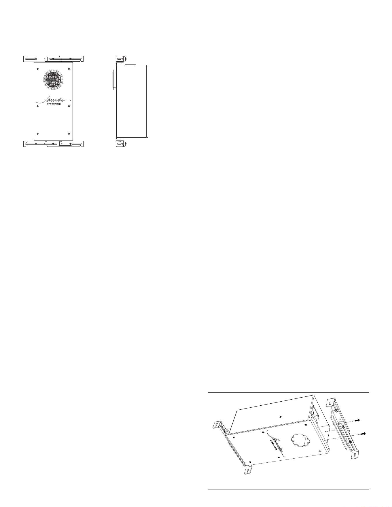
ASSEMBLING THE PARTS
The included SA Brackets are designed for 16” on-center
constructions and can accommodate construction from
7.9” to 16.75” inner spacing between joists.
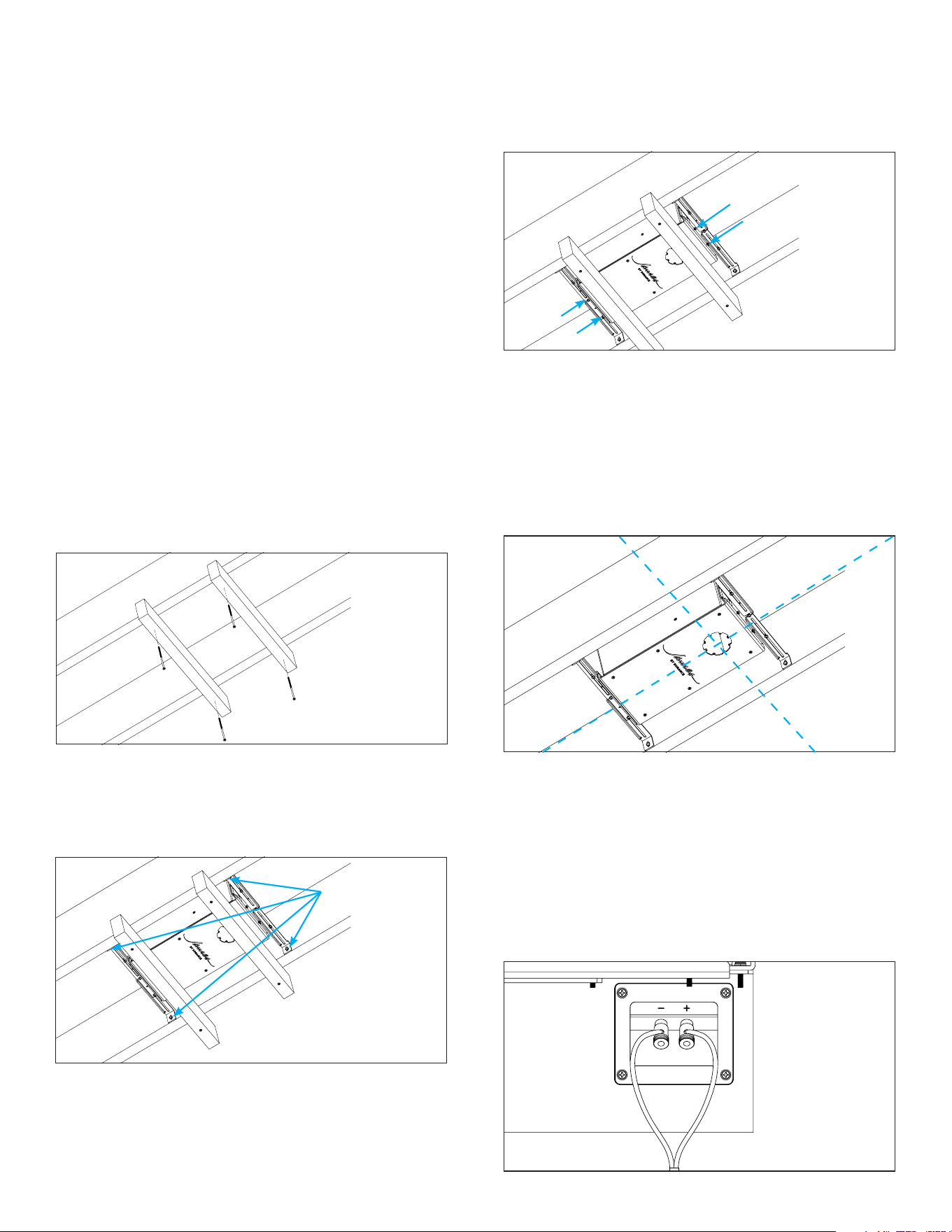
1. Attach the brackets to the SA68-ENC using the
supplied 8/32 screws, lock washers, and flat washers
(see Figure 1).
Figure 1: Assembling the Parts
REQUIRED PARTS (NOT INCLUDED)
(1) SA68-MOD Speaker Module | 60598
(1) SA Trim Kit (requires one of the following, see
chart on page 6)
• Retro Fit Trim (3” Round, 3” Square, 4” Round,
or 4” Square)
• Sheetrock Trim Retro Fit Trim (3” Round, 3”
Square, 4” Round, or 4” Square)
• Solid Surface Trim Retro Fit Trim (3” Round, 3”
Square, 4” Round, or 4” Square)
(1+) Spacer Ring(s)
• SA3-SP-0.125 1/8” SA Spacer | 60312
• SA3-SP-0.375 3/8” SA Spacer | 60311
3
INSTALLING THE SA68 SPEAKER
ENCLOSURE
1. Mount temporary holders to the joists in the
installation location. Cut two 2x4s or 1x2s a few
inches wider than the ceiling joists. Then with a
couple of drywall screws, mount the temporary
holders to the joists (drywall screws not included).
The temporary holders will help hold the speaker
in place and help position the speaker flush to the
future drywall (see Figure 2).
2. Position the SA68 Speaker Enclosure on top of the
temporary holders.
3. Fix the brackets to the joists by expanding each
bracket fully between the joists (see Figure 3).
Figure 2: Mount
Temporary Holders
4. Secure the brackets to the joists using drywall
screws. Make certain each bracket is flush with the
joists. Drywall screws not included.
5. Adjust the side-to-side position of the speaker as
needed by sliding the bracket, then tighten bracket
Figure 3: Fix and Secure
Bracket to Joists
10. Prepare the speaker wire by stripping the wire jacket
and inserting the wire strands into the appropriate
terminals on the SA68 Speaker Enclosure. Requires
minimum 18-gauge wire or heavier gauges for longer
wire runs (see Figure 6).
IMPORTANT: Connect the speaker module to the
enclosure opening to test for functionality BEFORE
installing drywall over the enclosure. Once tested,
remove the module and reserve for later.
Figure 5:
Adjusting the
speaker position
Figure 6: Wiring
the Terminals
2. Tighten the screws just enough to allow movement
for adjustment during installation.
IMPORTANT: This James Small Aperture Series
Speaker is installed behind the surface during pre-
construction framing, or as a renovation or remodel
installation. Both installations will require drywall
patching, mudding, and/or other final finish to the
surface.
NOTE: For Solid Surface installations like wood, begin
with the installation steps on page 4 in the section
titled SOLID SURFACE INSTALLATION with 3” or 4”
Solid Surface Trim Kit (Solid Surface Trimless Grille).
Upon completion of the outlined steps, return to this
section to continue installing the speaker enclosure.
screws, until reaching the desired position.
6. Tighten screws enough to securely fix the bracket
to the speaker enclosure. Be careful not to strip the
threads on the brackets (see Figure 4).
Tighten Screws
7. Remove drywall screws to loosen and remove the
temporary holders.
8. Ensure that the face of the speaker is plumb with
the joists.
9. Adjust if needed (loosen the bracket slightly and
adjust the speaker’s position up or down or as
required (see Figure 5).
Figure 4: Secure
Screws to Speaker
4
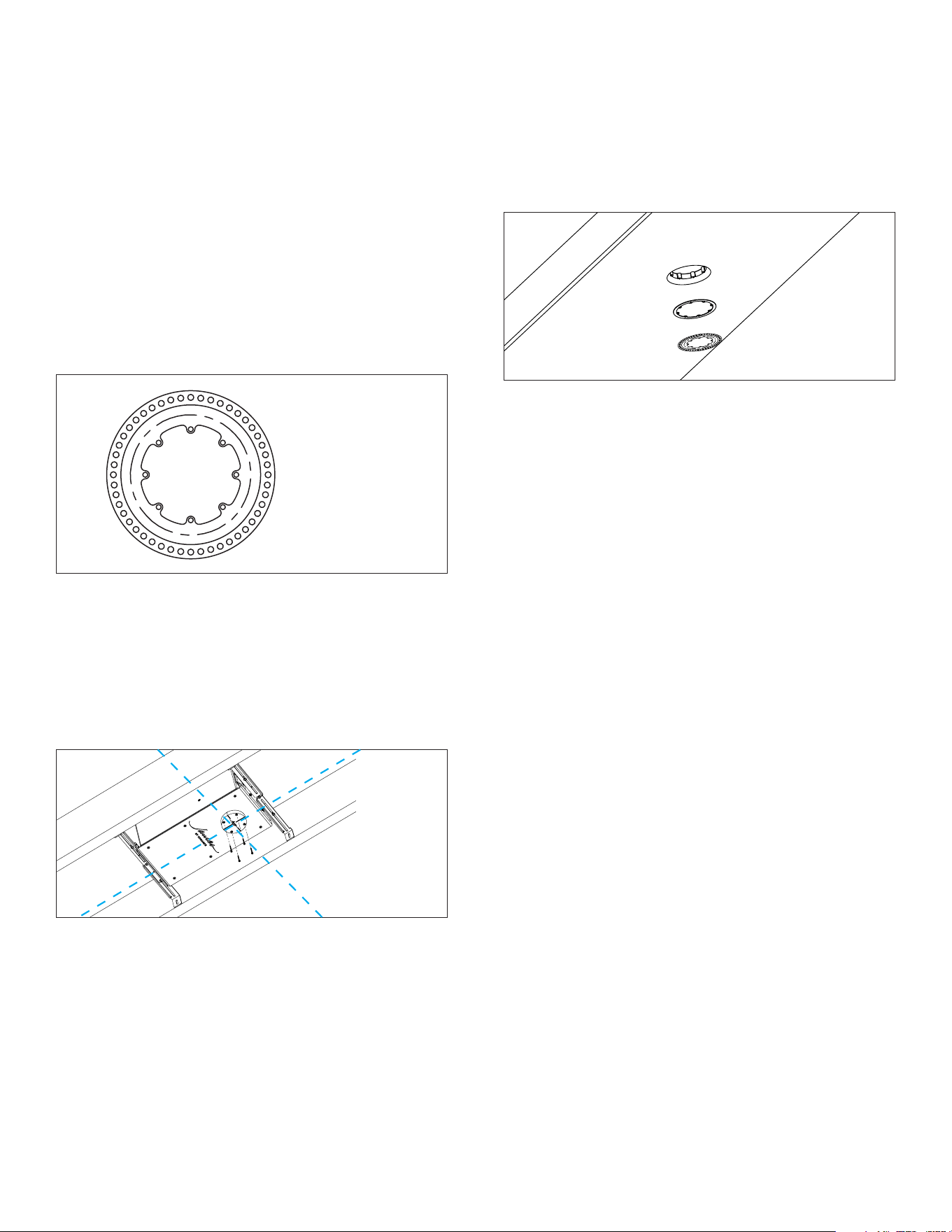
2. Add the appropriate size and shape Space Saver
(3” or 4”, round or square) to cover the opening
and secure with four screws into the available
hole threads, ensuring proper orientation and
alignment. Use the cross hairs of the space saver
along with a laser line to find proper alignment with
surrounding room elements like lighting hardware
and architectural sight lines (see Figure 8).
Figure 8: Attach
the Space Saver
3. Once the opening has been prepared and is
protected by the space saver, proceed to installing
the drywall ceiling over the speaker and around the
space saver. Complete steps 4-6 before proceeding
with taping and mudding drywall seams.
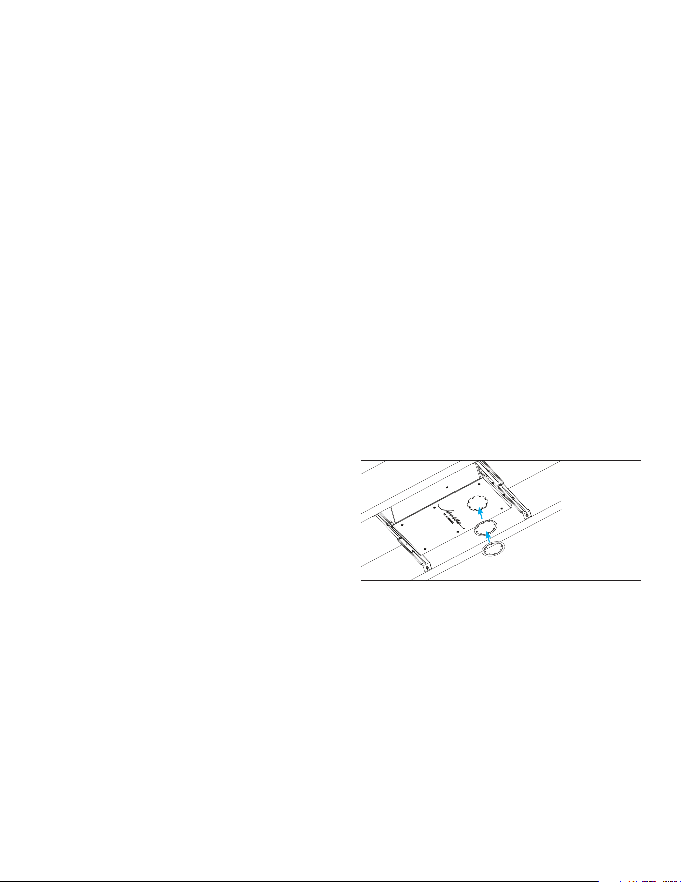
4. Once drywall/gypsum board has been installed
over the speaker and surrounding the space saver,
remove the Space Saver and install the appropriate
Sheetrock Trim Kit using four of the supplied 6-32
coarse head screws.
5. All trims accommodate 0.5” (12.7mm) surface
thickness. If the surface exceeds 0.5” thickness,
install the appropriate spacers between the trim kit
and enclosure to accommodate the surface depth.
James SA3 spacers are available in 1/8” (3.2mm)
and 3/8” (9.5mm) and can be stacked as required to
achieve the correct depth of the trim to the surface
(SA3-SP-0.125 and SA3-SP-0.375). Spacers can also
be custom made to accommodate up to 6” (152mm)
of surface thickness (see Figure 9).
PREPARING THE ENCLOSURE
OPENING AND FINISHING THE
SURFACE
Please refer to the section appropriate for your
installation type and application.
DRYWALL | GYPSUM BOARD
INSTALLATION WITH 3” OR 4”
SHEETROCK TRIM KIT
1. To achieve a trimless grille finish in drywall/gypsum
board applications, use the SA3-GRILLE-R-SR, SA3-
GRILLE-S-SR, SA4-GRILLE-R-SR, or SA4-GRILLE-S-
SR Sheetrock Trim Kit. These Trim Kits are available
in 3” or 4”, round or square, and allow for mudding
up to the grille for a clean finish (see Figure 7).
Figure 7:
Sheetrock Trim
6. Insert the foam dust guard into the trim kit.
7. Proceed to finishing the surface, taping and
mudding up to the trim kit. Paint over the entire
opening; the foam dust guard will protect the
speaker opening.
8. After the paint has fully dried, remove and discard
the Space Saver and foam dust guard.
9. See steps for INSTALLING THE SA68-MOD
SPEAKER MODULE.
SOLID SURFACE INSTALLATION WITH
3” OR 4” SOLID SURFACE TRIM KIT
Once the Small Aperture Enclosure and Module have
been installed and tested, the speaker location can be
identified on your ceiling material and precisely cut for
solid surface ceilings. The SA3 Router Template (60370)
or SA4 Router Template (60371) is recommended.
ATTACHING THE PLEXIGLASS ROUTER TEMPLATE
There are two methods for attaching the plexiglass
router template to the ceiling boards:
• Using Clamps: If feasible, use a pair of clamps to
secure the router template. Center the template’s
etched crosshair markings on the target location
and tighten the clamps.
• Using Double-Sided Carpet Tape: If clamps cannot
be used due to location or spacing constraints, apply
double-sided carpet tape to temporarily adhere the
router template to your material.
CUTTING A SQUARE OPENING
1. Once the template is in place, drill a hole in any
corner using a 3/8” drill bit as a starting point.
2. Using a 1/8” spiral router bit with a 5/16” bushing,
carefully follow the square template to outline the
cut. This will create a pre-cut line to follow with a
jigsaw.
Figure 9: Install
Appropriate
Spacers
5
3. Be careful not to cut too close to the edge of the
template.
4. Drill the remaining three holes in each corner,
ensuring you stay within the pre-cut groove.
5. Using a jigsaw, rough cut the opening, staying at
least 1/4” away from the edge of the router template.
6. We recommend this approach so that a 1/4” spiral
down-cutting bit with a 7/16” bushing can precisely
complete the outlined cut of the template.
7. After making the cut, verify that the opening is
accurate before loosening the clamps or removing
the tape and template.
8. Place the grille into the cut to check if any edges
require adjustment. If necessary, use a corner chisel
for corners and a file for additional adjustments.
9. Remove the router template and place the grille into
the material to ensure a flush fit.
CUTTING A ROUND OPENING
1. Using the template, drill a single hole in the center of
the material.
2. Using a 1/8” spiral router bit with a 5/16” bushing,
carefully follow the circular template to outline the
cut for the jigsaw.
3. Rough cut the opening along the guideline with a
jigsaw, staying at least 1/4” away from the edge of
the router template.
4. Using a 1/4” spiral down-cutting bit with a 7/16”
bushing, complete the outlined cut of the template.
5. Make minor adjustments to the material as needed
to ensure a precise fit.
6. Remove the router template and place the grille into
the material to ensure a flush fit.
See steps for INSTALLING THE SA68-MOD SPEAKER
MODULE.
DRYWALL | SOLID SURFACE
INSTALLATION WITH 3” OR 4” RETRO
FIT TRIM KIT
The James Retro Fit Trim Kit (with bezel grille that sits
proud of an installation surface) can be selected for
any surface installation (drywall or solid surface). This
trim allows for greater opening coverage to better fit
into drop ceiling installations or into surfaces where the
opening cutout has a gap or imperfections.
1. Add the appropriate size and shape Space Saver
(3” or 4”, round or square) to cover the opening
and secure with four screws into the available
hole threads, ensuring proper orientation and
alignment. Use the cross hairs of the space saver
along with a laser line to find proper alignment with
surrounding room elements like lighting hardware
and architectural sight lines.
2. Once the opening has been prepared and is
protected by the space saver, proceed to installing
the drywall or solid surface ceiling over the speaker
and around the space saver. Refer to the SOLID
SURFACE INSTALLATION section for instructions
on creating precise cutouts for the speaker in a solid
surface material such as tongue and groove wood
ceilings.
3. Once drywall/gypsum board has been installed
over the speaker and surrounding the space saver,
remove the Space Saver and install the appropriate
Retro Fit Trim Kit using four of the supplied 6-32
coarse head screws.
4. All trims accommodate 0.5” (12.7mm) surface
thickness. If the surface exceeds 0.5” thickness,
install the appropriate spacers between the trim kit
and enclosure to accommodate the surface depth.
James SA3 Spacers are available in 1/8” (3.2mm)
and 3/8” (9.5mm) and can be stacked as required to
achieve the correct depth of the trim to the surface
(SA3-SP-0.125 and SA3-SP-0.375). Spacers can also
be custom made to accommodate up to 6” (152mm)
of surface thickness (see Figure 10).
See steps for INSTALLING THE SA68-MOD SPEAKER
Figure 10: Stacking
Spacers
MODULE.
INSTALLING THE SA68-MOD SPEAKER
MODULE
1. If applicable, remove the foam guard or space saver
to reveal the speaker enclosure opening.
2. Connect the 2-pin connector from the enclosure
to the 2-pin connector on the back of the speaker
module. Ensure the connector orientation is correct.
3. Insert the speaker module into the opening and
secure it to the enclosure using four screws.
6
• Do this by shining a flashlight into the port
openings that surround the installed speaker
module.
• Perform a full 360° check, closely inspecting the
entire length of the port inside the enclosure
around the entire perimeter of the port.
• Look for any area where the cable is bunched up
and potentially blocking the port.
• If any obstructions are found, use a long, thin
tool such as a flat blade screwdriver to push the
cable obstruction further into the port until the
port is 100% clear.
• Best practice is to push the screwdriver into
every opening around the port and keep
pushing until the cable is cleared out of the way.
• After this process, double check with a flashlight
to confirm there are no port obstructions.
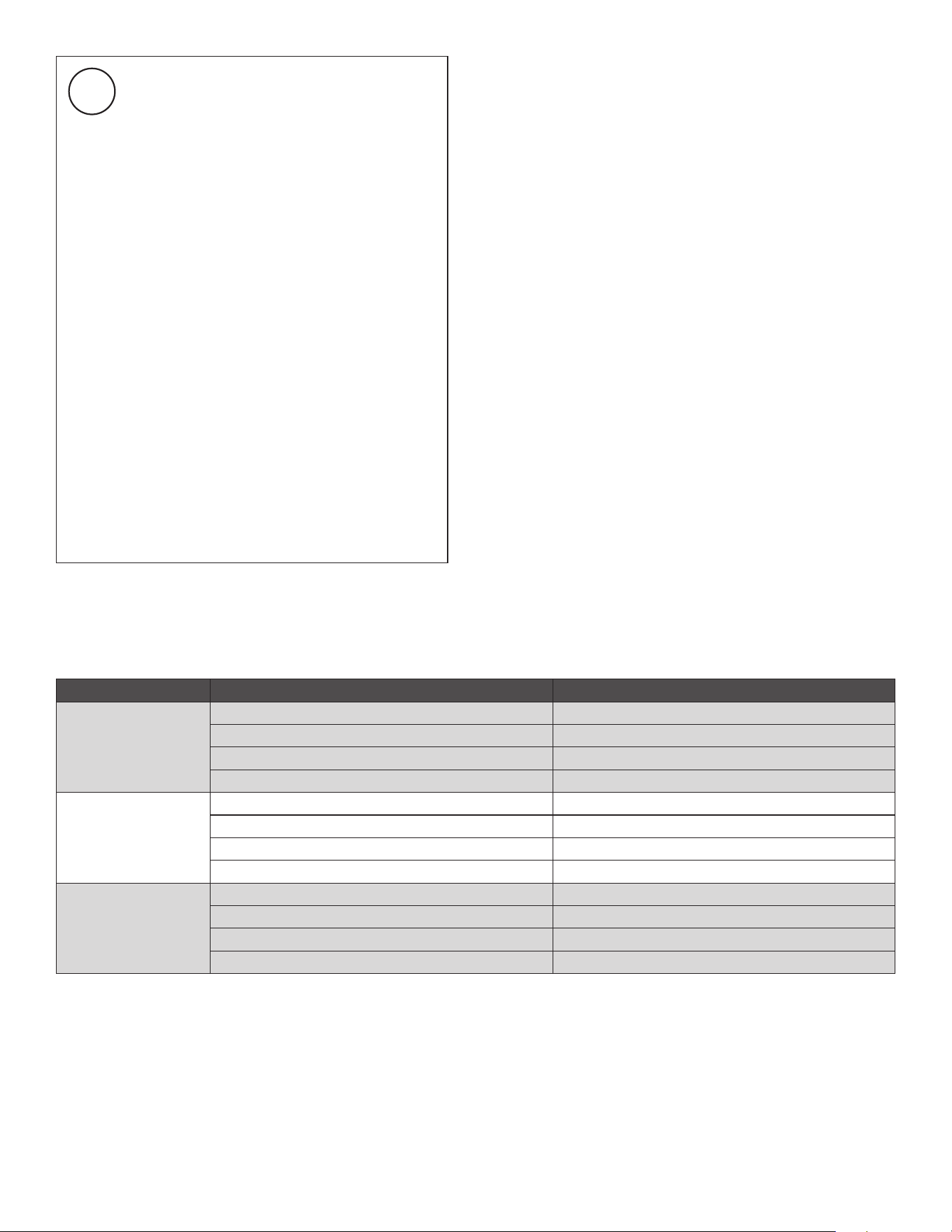
SURFACE GRILLE MODEL | SKU
Sheet Rock
3” Round Trimless
SA3-GRILLE-R-SR | 60315
3” SquareTrimless
SA3-GRILLE-S-SR | 60313
4” Round Trimless
SA4-GRILLE-R-SR | 60309
4” SquareTrimless
SA3-GRILLE-S-SR | 60306
Retro Fit
3” Round Bezel Proud
SA3-GRILLE-R-RF | 60316
3” Square Bezel Proud
SA3-GRILLE-S-RF | 60201
4” Round Bezel Proud
SA4-GRILLE-R-RF | 60310
4” Square Bezel Proud
SA4-GRILLE-S-RF | 60307
Solid Surface
3” Round Trimless
SA3-GRILLE-R-SS | 60314
3” SquareTrimless
SA3-GRILLE-S-SS | 60268
4” Round Trimless
SA4-GRILLE-R-SS | 60308
4” SquareTrimless
SA4-GRILLE-S-SS | 60305
TRIM KIT OPTIONS
4. Complete the installation by testing the speaker
with an audio source. Verify proper functionality and
sound quality across dierent frequency ranges.
5. Attach the included adhesive foam strips in four
equidistant locations on the grille flange.
6. Install the press-fit grille that matches your chosen
trim style.
IMPORTANT: After installing the speaker
module, check for and remove any cable
obstructions inside the port. The cable
can block air flow and hinder the speaker
performance.

7
SA68
SKU SA68-ENC | 60597 + SA68-MOD | 60598
Woofer 6.5” (165mm) Thin Ply Carbon Fiber/Rohacell cone, rubber surround
Wide Bandwidth Driver 2.0” (50mm) Thin Ply Carbon Fiber cone, rubber surround
Frequency Response 45Hz - 25kHz +/-3dB
Frequency Range 35Hz–30kHz +/-10dB
Impedance 8 ohms nominal; 6 ohms minimum
Power Handling 5 watts minimum; 150 watts maximum
Sensitivity 82dB SPL (2.83V/1 meter)
Enclosure Only (WxHxD) 7.75” x 15.625” x 6.375” (196.85mm x 396.88mm x 161.93mm)
Enclosure With Bracket (WxHxD) 7.9” x 18.125” x 6.375” (200.66mm x 460.38mm x 161.93mm)
Minimum Installation Width 7.9” (200.66mm)
Maximum Installation Width 16.75” (425.45mm)
Shipping Weight 22 lbs
TECHNICAL SPECIFICATIONS

8
©2025 Sonance. All rights reserved. Sonance is a registered trademarks of Dana Innovations. Due to continuous product improvement, all features and
specifications are subject to change without notice. For the latest Sonance product specification information visit our website: www.sonance.com
SONANCE • 991 Calle Amanecer • San Clemente, CA 92673 USA • PHONE: (949) 492-7777 07.11.2025
WARRANTY
James by Sonance warrants to the original end-user purchaser that this Sonance or James-brand product (“Product”), when purchased
from an authorized Sonance or James Dealer/Distributor, will be free from defects in materials and workmanship under normal use,
subject to the following terms:
LIMITED LIFETIME WARRANTY: If installed indoors, James Small Aperture speakers are covered by a limited lifetime warranty for the
original purchaser, ensuring long-term performance and reliability.
LIMITED FIVE (5) YEAR WARRANTY: If installed outdoors or in moisture-dense environments such as spas, showers, or saunas, James
SA speakers are covered by a limited five (5) year warranty from the date of purchase.
GRILLE WARRANTY: The speaker grille is warranted for five (5) years for both indoor and outdoor installations.
This warranty applies only to products purchased from authorized James by Sonance dealers and installed in accordance with
manufacturer guidelines. It does not cover damage resulting from misuse, accidents, unauthorized modifications, improper installation, or
normal wear and tear.
EXCLUSIONS: TO THE EXTENT PERMITTED BY LAW, THE WARRANTY SET FORTH ABOVE IS IN LIEU OF, AND EXCLUSIVE OF, ALL
OTHER WARRANTIES, EXPRESS OR IMPLIED, AND IS THE SOLE AND EXCLUSIVE WARRANTY PROVIDED BY SONANCE. ALL OTHER
EXPRESS AND IMPLIED WARRANTIES, INCLUDING THE IMPLIED WARRANTIES OF MERCHANTABILITY, IMPLIED WARRANTY OF
FITNESS FOR USE, AND IMPLIED WARRANTY OF FITNESS FOR A PARTICULAR PURPOSE ARE SPECIFICALLY EXCLUDED. NO ONE
IS AUTHORIZED TO MAKE OR MODIFY ANY WARRANTIES ON BEHALF OF SONANCE.
The warranty stated above is the sole and exclusive remedy and James by Sonance’s performance shall constitute full and final
satisfaction of all obligations, liabilities and claims with respect to the Product.
IN ANY EVENT, SONANCE SHALL NOT BE LIABLE FOR CONSEQUENTIAL, INCIDENTAL, ECONOMIC, PROPERTY, BODILY INJURY, OR
PERSONAL INJURY DAMAGES ARISING FROM THE PRODUCT, ANY BREACH OF THIS WARRANTY OR OTHERWISE.
This warranty statement gives you specific legal rights, and you may have other rights which vary from state to state. Some states do
not allow the exclusion of implied warranties or limitations of remedies, so the above exclusions and limitations may not apply. If your
state does not allow disclaimer of implied warranties, the duration of such implied warranties is limited to period of Sonance’s express
warranty.
Your Product Model and Description: James SA68 Small Aperture Speaker.
Additional Limitations and Exclusions from Warranty Coverage: The warranty described above is non-transferable, applies only to the
initial installation of the Product, does not include installation of any repaired or replaced Product, does not include damage to allied
or associated equipment which may result for any reason from use with this Product, and does not include labor or parts caused by
accident, disaster, negligence, improper installation, misuse (e.g. overdriving the amplifier or speaker, excessive heat or cold or humidity,
outdoor installation), or from service or repair which has not been authorized by Sonance.
Obtaining Authorized Service: To qualify for the warranty, you must contact your authorized Sonance Dealer/Installer or call Sonance
Customer Service at (949) 492-7777, must obtain a return merchandise number (RMA), and must deliver the Product to Sonance
shipping prepaid during the warranty period, together with the original sales receipt, or invoice or other satisfactory proof of purchase.
In order to initiate a warranty claim:
1. Contact Sonance Technical Support with a description of the fault, the product’s serial number and the date of purchase from an
authorized Sonance dealer at: [email protected]
2. Sonance Technical Support will follow-up and may request additional troubleshooting.
3. Once a determination has been made on the fault, Sonance Customer Service will follow-up by email. Please have a scanned copy of
your Sonance Small Aperture Speaker sales invoice ready to send upon request to document the speaker’s warranty status.
4. Sonance Customer Service will provide an RMA number to be included on the shipping label of the packaging. Please send the
speaker back in its original factory carton, which has been specifically designed to protect the speaker during transit.
Contact us at: www.sonance.com/company/contact