
1
Installation and Operating Instructions
Built in GAS Cooktops
Please note: This cooktop must be installed by an authorised installer.
The enclosed installation check list must be completed and signed off
by the installer with the installer’s Licence number recorded to activate
the Warranty.
Call Service 1 300 307 917

2

3
IMPORTANT! This booklet is a fundamental part of the appliance, and it should be retained. Read all
instructions carefully before using the appliance.
This appliance is to be installed by a qualified technician in accordance with the gas installation
code AS5601, SAA wiring rules, as well as the requirements of all local statutory and building
authorities and regulations. This appliance is for domestic use only and has been designed for
cooking and heating food. Any other use is considered improper.
The manufacturer is not responsible for bad installation, tampering, unskilled use and usage
other than that it is intended for.
• Check that the product has not been damaged during transport.
• Packing elements (plastic bags, expanded polystyrene, nylon etc) are potentially dangerous
and must be kept away from children.
• Packing is made up of recyclable material and is marked by the
symbol.
• This appliance is only to be used by adults. Make sure the children do not touch the
controls or play with the appliance.
• The data plate with its technical data is in a visible position under the housing. There is
another data plate enclosed that should be attached to a handy surface for future reference.
The data plate under the housing must never be removed.
• The illustrations for using the appliance are in the final pages of this booklet.
• DO NOT SPRAY AEROSOLS IN THE VICINITY OF THIS APPLIANCE WHILE IT IS IN
OPERATION
• NOT SUITABLE FOR USE IN MARINE CRAFT, CARAVAN OR MOBILE HOME
• WARNING: ACCESSIBLE PARTS BECOME HOT IN USE. TO AVOID BURNS AND
SCALDS CHILDREN SHOULD BE KEPT AWAY.
• DO NOT MODIFY THIS APPLIANCE.
• SERVICE MUST BE CARRIED OUT BY AUTHORISED SERVICE PERSONNEL
• DO NOT USE THIS APPLIANCE AS A SPACE HEATER
• DO NOT USE OR STORE FLAMMABLE MATERIALS IN OR NEAR THIS APPLIANCE
Safety hints and usage tips
• After use ensure that all controls are in the off position
• Never leave cooking food unattended during use as this can lead to a fire risk.
• Be aware of wearing loose garments while cooking as these may catch vessel handles or
catch fire.
• Always turn pan handles to the side or to the back of the cooktop where they can’t be knocked
or reached by children.
Warning:
This appliance is designed to be built into a kitchen bench capable of withstanding the weight of the
appliance during its use.
4
♦ The kitchen bench must be resistant to temperatures of at least 100°C. Check with the
manufacturer of the bench material to be sure. No liability will be accepted for damage to bench
materials that do not comply.
♦ See the relative paragraph and drawings for correct installation.
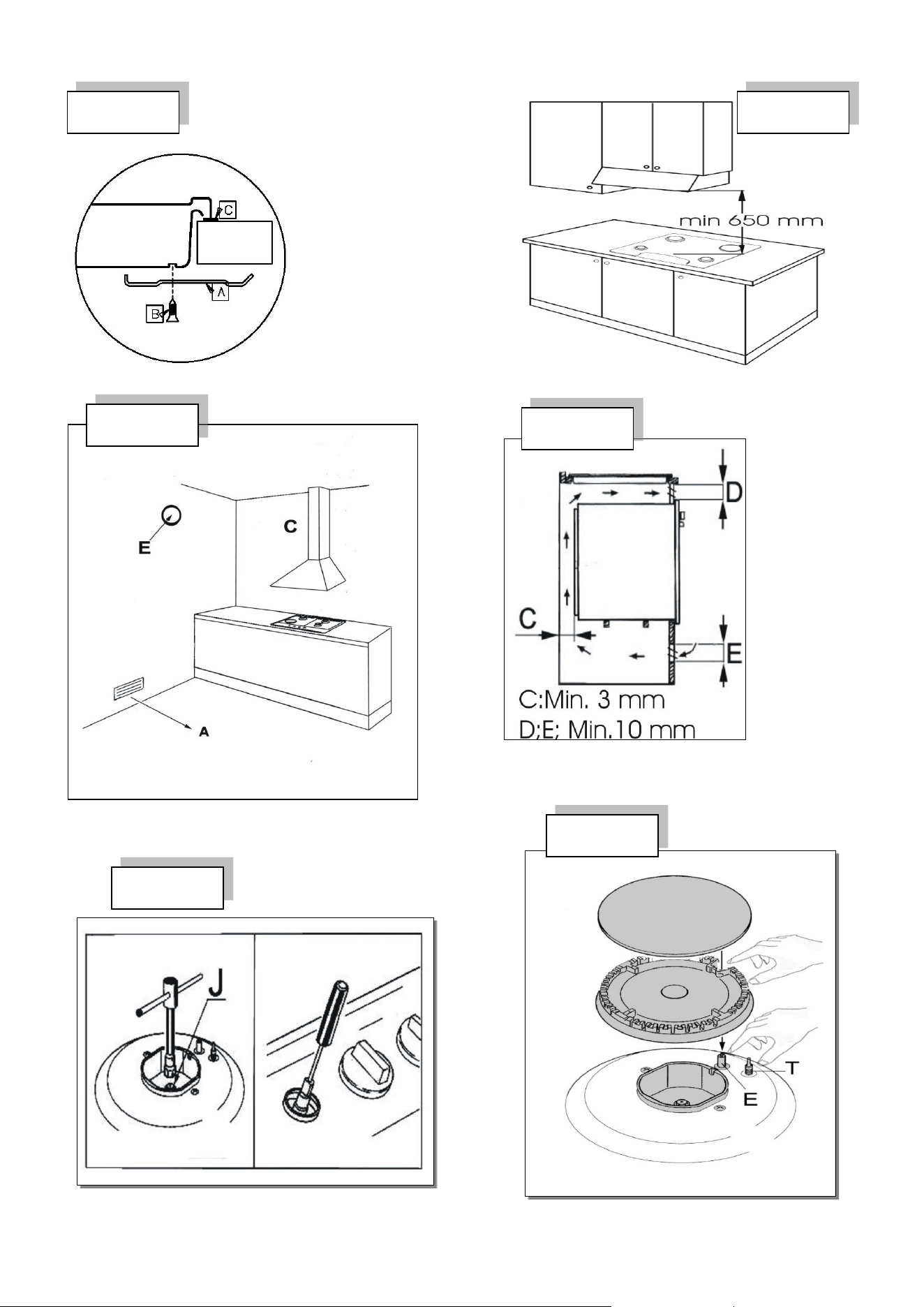
♦ Using a gas cooking appliance causes heat and humidity in the location where it is installed. Make
sure that the kitchen is adequately ventilated, install a range hood if required. See fig. 16 & 17.
This booklet covers several models. You can see your model number on the data plate:
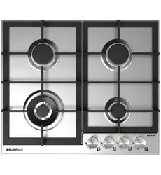
MODELS
EMILIA BRAND MODELS
GLEM GAS BRAND MODELS
Emilia SEC64GWI
60cm cooktop with 4 burners
1. Medium front burner
2. Medium back burner
3. Small burner
4. Large Wok burner
Glem Gas GTD64AU
60cm cooktop with 4 burners
1. Medium front burner
2. Medium back burner
3. Small burner
4. DCC Wok burner
Emilia SEC75GWI
70cm cooktop with 5 burners
1. Small burner
2. Large burner
3. Medium back burner
4. Medium front burner
5. Wok burner
Glem Gas GTD75AU
75cm cooktop with 5 burners
1. Small burner
2. Large burner
3. Medium back burner
4. Medium front burner
5. DCC burner
Glem GTD95AU
90cm cooktop with 5 burners
1. Small burner
2. Medium back burner
3. Large burner
4. Medium front burner
5. DCC burner

5
LIGHTING THE GAS BURNERS
Gas Burners
The gas flow to each burner is controlled by the corresponding knob. The graphic symbols printed on
the control panel indicate the following settings:
Valve closed: No gas flow
Maximum capacity: Maximum gas flow
Minimum capacity: Minimum gas flow
Turning On and Off
Each control knob is clearly labelled to show which burner it operates.
Lighting with Electronic Ignition
To light a burner:
1. Press and turn the control knob to the maximum position.
2. Hold the knob down until the burner ignites and then for a further few seconds.
3. Adjust the flame to the desired level by turning the knob.
Note: If the burner does not ignite easily at the maximum setting due to local gas pressure, repeat the
process with the knob turned slightly lower.
Lighting without Electronic Ignition
In the event of a power failure:
1. Bring a flame close to the top of the burner.
2. Press and turn the control knob anticlockwise until it aligns with the ignition symbol on the
panel.
3. To turn the burner off, rotate the knob clockwise until it points straight upwards.
Lighting with Safety Valves
All models are fitted with flame failure safety valves, which automatically stop the gas supply if the
flame goes out.
When lighting the burner:
1. Turn the control knob to maximum and press it down.
2. Hold for 4–5 seconds to allow the sensor tip to heat up.
3. Release the knob and adjust the flame as desired.
If the flame goes out, repeat the process and hold the knob down for a few seconds longer.
Warning
• Do not activate the electronic ignition for more than 15 seconds.
• If the burner does not ignite, wait one minute before trying again.
6
USING THE GAS COOKTOP
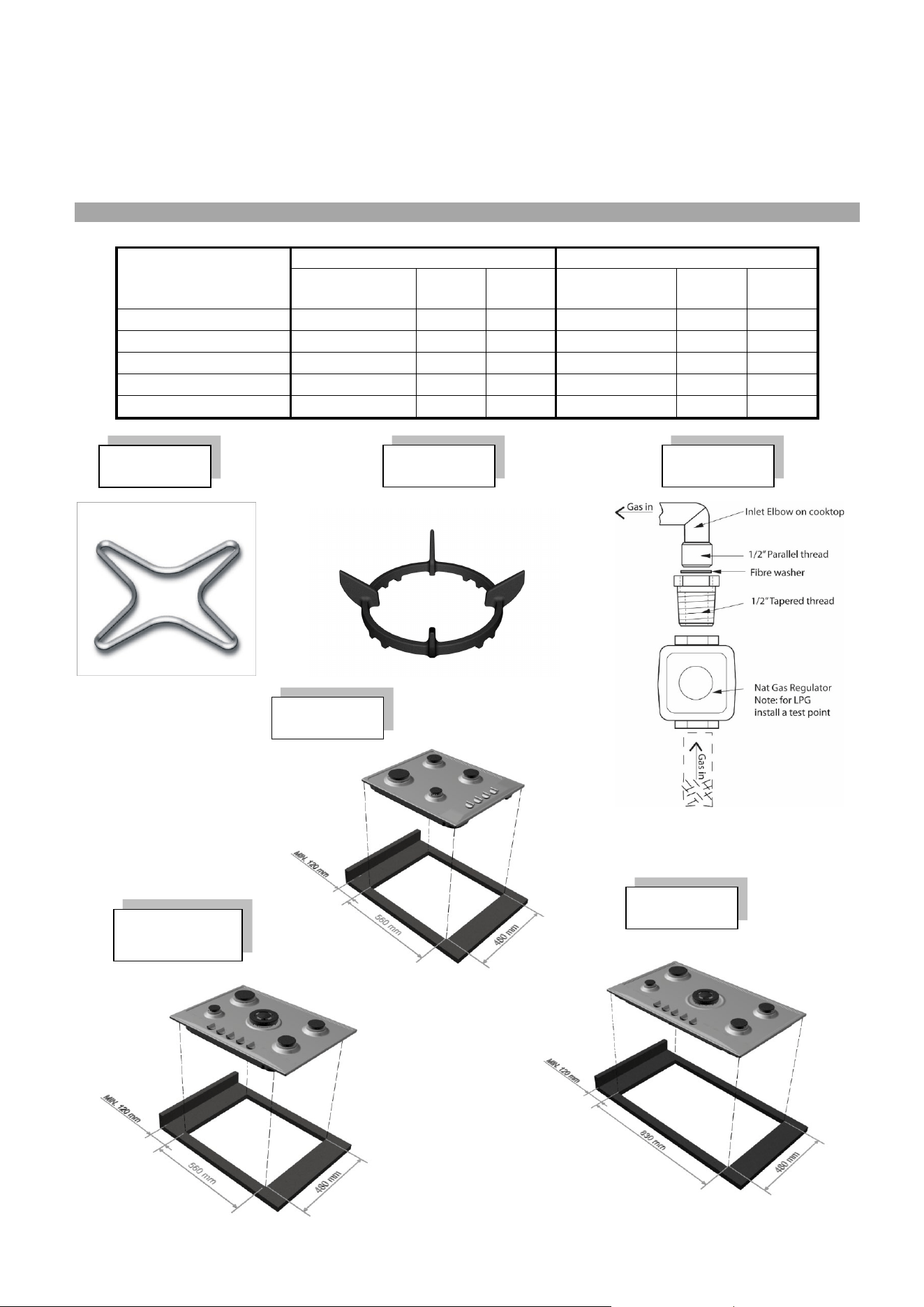
Pan Supports (Trivets)
The trivets are designed to make the cooktop safe and easy to use. Before each use, ensure that they
are correctly positioned and stable. Also, check that the supporting rubbers are intact and properly
seated.
Small Vessel Support (optional Fig. 1)
Use the auxiliary burner ring (the smallest) only for small-diameter vessels. This prevents tipping and
ensures optimal efficiency.
Wok Burner Stand (Fig. 2 – optional, design may vary)
The wok stand is intended exclusively for WOKs with concave bases. To prevent serious burner
malfunction, always use the wok stand with curved-bottom WOKs and never with flat-bottom vessels.
Choosing the Burner
Select the burner that best suits the diameter and capacity of your pan (see table). Matching the pan size
to the burner power is essential to achieve maximum efficiency.
Pan diameter
Burner
Minimum diameter
Maximum diameter
Auxiliary
60 mm (with reduction)
140 mm
Semi-rapid
160 mm
200 mm
Rapid
200 mm
240 mm
Triple crown wok
240 mm
260 mm
Dual control
240 mm
260 mm
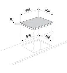
GAS COOKTOP INSTALLATION
Installation on the Kitchen Bench
The cooktop must be installed only on heat-resistant surfaces (minimum temperature 100°C). To comply
with AS5601 regulations, maintain a clearance of 120 mm from all combustible surfaces.
The required cutout dimensions for the kitchen bench, as well as the minimum distances from the back,
side, and overhead walls, are illustrated in Figures 3, 4, and 5.
Important notes:
1. If the cooktop is installed over a vacant cavity (without an oven beneath), a separate panel must
be fitted under the cooktop base, leaving a minimum gap of 10 mm.
2. If installed over an oven, a divider panel must be placed with a minimum clearance of 15 mm,
following the oven manufacturer’s instructions to maintain proper ventilation (see Fig. 8).
3. The electrical connections for the cooktop and oven must be made separately.
4. It is recommended to use ovens with forced internal cooling, such as all models from Glem Gas
and Emilia.
Fixing the Cooktop
To secure the cooktop to the kitchen bench:
1. Apply the supplied sealing gasket around the outer edge of the bench cutout. Ensure the ends
meet perfectly without overlapping.
2. Carefully place the cooktop into the cutout, making sure it is centered.
3. Secure the cooktop to the bench using the mounting brackets as shown in Fig. 6.
4. When properly installed, the gasket prevents liquids from entering beneath the cooktop.
7
Connecting the Gas
Important: These instructions are intended for qualified installers only. The appliance must be installed
in accordance with local laws and standards. Disconnect the electrical supply before servicing.
Gas Inlet Connection Points:
• 60 cm and 70 cm cooktops: 215 mm from the left-hand edge, 40 mm from the rear edge of the cutout
• 90 cm cooktops: 799 mm from the left-hand edge, 40 mm from the rear edge
These technical instructions are for authorised personnel. All local gas and electrical regulations must be
followed. Consult AG601/AS5601 as applicable.
Installation Guidelines:
1. Verify that the gas type (natural gas or LPG) matches the cooktop. Check the product plate and
this booklet.
2. Gas inlet fitting: ½” BSP male thread.
3. Refer to Figure 2A for the gas connection location.
4. Fit the supplied regulator (for natural gas) or LPG test point, as applicable.
5. Installing an isolating valve and union is recommended for easy disconnection during servicing.
These should be accessible.
6. Check all connections for gas tightness using soapy water or another approved method.
Flexible Hose Connection
• Use a hose assembly that complies with AS/NZ1869 (AGA approved), 10 mm ID Class B or D,
and in accordance with AS5601.
• Hose length must not exceed 1.2 m.
• Ensure the hose does not contact hot surfaces of the cooktop, oven, or nearby appliances.
• Avoid contact with drawers, abrasion, or kinking.
• Test all joints for leaks using soapy water.
Final Check
Operate each burner at high and low flames to ensure proper ignition and stable flame.
Potential Abnormalities:
• Yellow tipping on flames
• Soot on the underside of pots
• Burners failing to ignite properly
• Burners failing to remain lit
Once the cooktop operates correctly, explain proper usage to the user. If adjustment cannot correct
performance, contact Glem Gas for assistance.
CONVERSION TO DIFFERENT TYPES OF GAS
VERSION TO DIFFERENT TYPES OF GAS
Converting the Cooktop to a Different Gas
If the cooktop needs to be converted to a gas type different from its original specification, the injectors
must be replaced.
• Spare injectors can be obtained from Glem Gas Service if not supplied.
• Install injectors according to the table on the underside of the cooktop.
• Injectors are identified by their diameter, expressed in hundredths of a millimeter, printed on each
injector.
Modify the inlet gas supply as required and fit the Natural Gas regulator or LPG test point, depending on
the gas type.

8
Replacing the Injectors
1. Remove the gas rings and burner caps from the cooktop.
2. Using a spanner, replace injectors “J” (Fig. 10) with those specified for the gas type.
3. Reassemble the burners. No primary air adjustment is required.
Regulating the Minimum Flame
1. After replacing the injectors, ignite the burner and remove the control knob.
2. Turn the knob to minimum, insert a screwdriver, and adjust the screw:
o Turn clockwise to decrease the flame
o Turn anticlockwise to increase the flame (Fig. 10)
The flame should be small, stable, and evenly distributed around the burner crown.
• Ensure the flame remains lit when quickly turning the control from maximum to minimum.
• For cooktops with flame failure devices, verify the flame slightly touches the thermocouple.
• Leave the burner on for a few minutes to confirm stability; if it goes out, slightly increase the
minimum flame.
Gas Pressure Checks and Adjustment
1. Shut off the gas supply.
2. Remove the sealing screw from the regulator test point or LPG test point at the rear of the cooktop
and attach a manometer.
3. Turn the gas supply back on and ignite the largest and smallest burners at maximum.
4. Check the gas pressure and adjust the regulator as required to match the values on the table or
data plate.
o For LPG, adjust at the cylinder regulator:
Turn clockwise to increase pressure
Turn anticlockwise to decrease pressure
5. Refit the test point sealing screw when complete.
COOKTOP MAINTENANCE
To keep the cooktop in good condition, it should be cleaned after each use once it has cooled.
Important: Never remove the control knobs from their housing for cleaning.
Enamel Parts
• Clean enamel surfaces with a sponge and soapy water or other non-abrasive products.
• Dry thoroughly to prevent spotting or damage.
Stainless Steel
• Wipe the stainless steel plate with a damp cloth or use products specifically designed for
stainless steel.
• After rinsing, dry with a soft cloth.
• Avoid spray cleaners on the printed graphics and be careful when wiping so as not to damage
them.
Cast Iron Trivets
• Wipe trivets with a damp cloth once cooled.
• Do not use harsh detergents or cleaning agents.
• Dry carefully to prevent spots or marks.
Burners
• Burners consist of two removable parts and can be cleaned with suitable products.
• After cleaning, ensure they are completely dry before replacing them in their housings.
• Always keep the following clean:
o Electrode “E” (Fig. 11)
o Safety probe “T” (Fig. 11) to ensure proper operation of the safety valve
• Carefully replace burners into their housings.
• Do not use the electric ignition when burners are not in place to avoid damage.
9
Ongoing Maintenance
• The cooktop requires no special maintenance, but a full check every two years is
recommended.
• If the control knobs become stiff or there is a gas smell, close the main gas valve and call for
service. The faulty valve may need replacement.
GAS CONSUMPTION AND INJECTOR SIZES
Burner & Model
Natural Gas
LPG
Inj Diam
MJ/H
Gas
Press
Inj Diam
MJ/H
Gas
Press
Wok Burner
1.70
14.0
1,0
0.97
13.0
2.75
DCC Burner
1.75
14.6
1.0
0.97
13.0
2.75
Large Burner
1.40
10.0
1.0
0.85
11.0
2.75
Medium Burner
1.10
6.1
1.0
0.65
6.9
2.75
Small Burner
0.90
4.0
1.0
0.50
3.8
2.75
Fig.
1
Fig.
2
Fig. 3 60cm
Fig. 4
70 & 75cm
Fig. 5 90cm
Fig.
2A
10
Fig.
6
Fig.
7
Fig.
8
Fig.
10
Fig.
9
Fig.
11
11
GLEM GAS AUSTRALASIA PTY. LTD. PRODUCT WARRANTY
Thank you for choosing a Glem Gas Appliance, the purchase of this appliance is an important investment in your home and so to protect your
investment we urge you to complete the registration card attached, please return it immediately.
IT IS A WARRANTY REQUIREMENT THAT PROOF OF PURCHASE BE PROVIDED PRIOR TO REQUESTING A SERVICE CALL.
THIS WARRANTY SHALL NOT APPLY IF THE APPLIANCE WAS NOT INSTALLED BY A LICENSED TECHNICIAN AND PROOF IS NOT
SUPPLIED.
The benefits conferred by this warranty are in addition to all other conditions and warranties in respect of this product which the consumer
may have under the Trade Practices Act 1874 of the Commonwealth of Australia and/or similar State or Territory Laws.
Our goods come with guarantees that cannot be excluded under the Australian Consumer Law. You are entitled to a replacement or refund for
a major failure and for compensation for any other reasonably foreseeable loss or damage. You are also entitled to have the goods repaired
or replaced if the goods fail to be of acceptable quality and the failure does not amount to a major failure.
Glem Gas Australasia Pty Ltd warrants, this appliance to be free from defects in workmanship and materials for a period of:
a) Where the appliance is intended to be used and is used for DOMESTIC USE – 24 MONTHS FROM DATE OF DELIVERY TO THE
ORIGINAL PURCHASER.
b) Where the appliance is intended to be used and is used for COMMERCIAL USE – 90 DAYS FROM DATE OF DELIVERY TO THE
ORIGINAL PURCHASER.
Glem Gas Australasia Pty Ltd, during the period of warranty, will at its option, and subject to the terms and conditions stated below, repair or
replace free of charge this appliance or any component part, which upon examination by Glem Appliances P/L. is found to be defective.
THIS WARRANTY SHALL NOT APPLY:
a) If the rating plate has been removed or the serial number or other details on it have been removed or rendered illegible.
b) If the appliance is connected to any gas type or voltage other than shown on rating plate.
c) If the appliance has been subjected to misuse, abuse accident or want of care.
d) If the appliance has been installed, operated or maintained contrary to the instructions supplied by Glem Gas Australasia Pty Ltd.
e) If any defect or failure is due to connection to an inadequate or faulty gas or power supply.
f) If damage is caused by foreign objects in or on the appliance or by reason of its use for purposes other than that for which it was
delivered.
g) If a repair has been made or attempted by the purchaser.
h) Where the oven is installed outside an 80km radius from the GPO of any Australian Capital City to freight and travel costs beyond that
radius.
Parts covered under warranty that need replacing i.e.: seals, knobs and burner caps. These can be posted to customer to put on at their
discretion.
This Warranty is given by Glem Gas Australasia Pty Ltd and no other person or organisation is authorised to vary its provisions and
conditions.
Complete this section and keep it for your own record.
Appliance type Model No. Serial no.
Purchased from Date of purchase
Please complete the section below and return to:
Glem Gas Australasia Pty. Ltd, PO Box 63 Blaxcell PO South Granville
Appliance type Model No. Serial no.
Purchased from Date of purchase
Customer Name Address
Installers Name Installers licence no.
Installers Signature
Installers Compliance Number COMPULSORY FOR WARRANTY
PLEASE NOTE THAT THE INSTALLER MUST BE A LICENCED GAS FITTER
GLEM GAS AUSTRALASIA PTY. LTD.
P.O. Box 63 Blaxcell PO South Granville NSW 2142
W: www.glemgas.com.au
Email us info@glemgas.com.au
Free call 1 300 307 917

12