Models:
-
YD2436GCSI18RD
-
YD4860GCSI18RD
REV250529
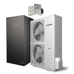
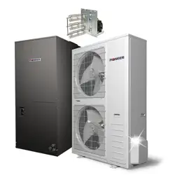
DUCTED CENTRAL SPLIT SYSTEM AIR CONDITIONER / HEAT PUMP
DYC-18 Inverter Series
For 24,000-60,000 BTU/hr Systems
Quantum Ultra (R-454B) - YD Outdoor (2/3 Ton & 4/5 Ton)
Installation &
User Manual
IMPORTANT NOTICE:
Read this manual carefully before installing or
operating your new air conditioning system. Be
sure to save this manual for future reference.

01 02 03 04 05 06 07 08
09 10 11 12 13 14 15 16 17 18
19 20 21 22 23 24 25 26 27 28
29 30 31 32 33 34 35 36 37 38
39 40 41 42 43 44 45 46 47 48
49
1.
Safety Symbols & Instructions ......................................................................... 2
2.
Considerations for Unit Location .................................................................... 13
3.
Unit Installation Preparation ........................................................................... 20
4.
Unit Settings ................................................................................................... 21
5.
Precautions for Refrigerant Pipeline .............................................................. 22
6.
Refrigerant Pipeline Routing .......................................................................... 24
7.
Refrigerant Line Brazing ................................................................................ 27
8.
Refrigerant Line Leakage Inspection ............................................................. 29
9.
Vacuuming ..................................................................................................... 30
10.
Service Valve ............................................................................................... 31
11.
Electrical-Low Voltage ................................................................................. 32
12.
Electrical-High Voltage ................................................................................. 37
13.
Start ............................................................................................................. 39
14.
System Refrigerant Charging Method ......................................................... 40
15.
System Operation & Troubleshooting .......................................................... 44
16.
Wiring Diagram ............................................................................................ 61
17.
Cleaning & Maintenance ............................................................................. 63
CONTENTS
18.
Water Float Switch Wiring ............................................................................ 64
19.
RS-485 Wiring & Thermostat ...................................................................... 65
20.
Disposal Guidelines .................................................................................... 68
Air Conditioner Installation & User Manual
1
1
Safety Symbols & Instructions
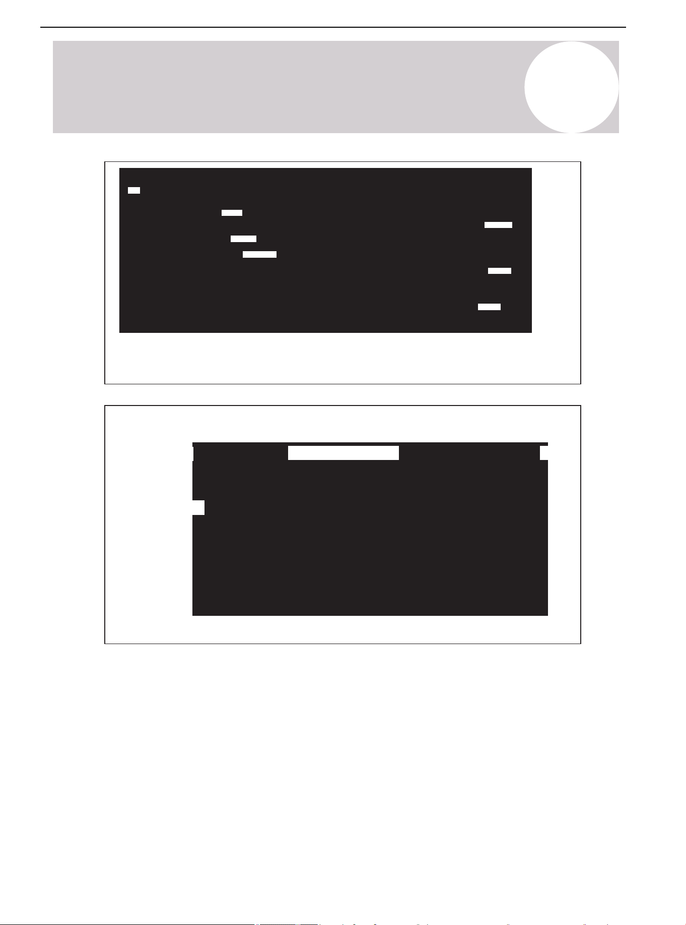
The following keywords are defined and used in this document:
Dangerous
Means a hazardous situation, which will lead to death or serious injury if not
avoided.
Warning
Indicates a hazardous situation, which may lead to death or serious injury if
not avoided.
Warning
The warnings in this document are identified by warning triangles printed
on a black background. The keyword at the beginning of the warning
indicates the type and severity of the risk if no measures are taken to
prevent it.
Symbol Keywords
Caution
Indicates a hazardous situation, which may cause mild to moderate injury if
not avoided.
Note
Used to deal with behaviors unrelated to personal injury.
Important Information
This symbol represents important information that is not harmful to people or property.
Air Conditioner Installation & User Manual
2
1
Safety Symbols & Instructions
Warning
Notice
Safety
Read before continuing
Failure to observe this warning may result in property damage, serious
personal injury, or death.
Before touching the electrical components, wait for 3 minutes after
disconnecting the power supply.
This document is the property of the customer and should be kept by
this unit. When finished, return the document to the service information
package.
These instructions do not cover all changes in the system, nor do they
provide all unexpected situations that may be encountered during
installation.
If more information is needed or there are special problems that are
not sufficient for the buyer, consult the installation or local dealers.
Maximum efficiency, best performance, and best overall system reliability are some of the benefits of
installing an approved indoor and outdoor split system.
Air Conditioner Installation & User Manual
3
01 03 04 05 06 07 08
09 10 11 12 13 14 15 16 17 18
19 20 21 22 23 24 25 26 27 28
29 30 31 32 33 34 35 36 37 38
39 40 41 42 43 44 45 46 47 48
49
1
Safety Symbols & Instructions
Warning:
• Qualified personnel with a certification for handling refrigerant fluids must install the unit. Refer to
the regulation and laws for the installation location.
• A certified technician must perform the installation, service, maintenance, and repairs of this unit.
• Only complete the servicing as recommended by the manufacturer.
• A certified technician must perform the product uninstallation and recycling.
• The appliance is designed to be operated in an outdoor area. If installing the appliance indoors is
needed, store the appliance in a room without continuously operating open flames (an operating
gas appliance) and ignition sources (an operating electric heater).
• Children aged 8 and above, as well as individuals with lack of experience or reduced physical,
sensory, or mental capabilities can only use the appliance if supervision or instruction is given.
Children must not play with or near the appliance. Children or untrained personnel should be
restricted from cleaning and performing maintenance on the appliance, unless they're given
supervision.
• Install the appliance in accordance with national wiring regulations.
• Before accessing the connection terminals, disconnect all power circuits.
• This information is intended to be used by individuals with sufficient electrical and mechanical
experience background. Attempting to repair central air conditioning products may result in
personal injury and/or property damage.
Warning: Dangerous Voltage
• Failure to observe this warning may result in property damage, serious personal injury, or death.
• Can cause injury or death. Disconnect all remote electric power supplies before servicing. Follow
proper locking/tagging procedures to ensure that the power supply will not be energized
accidentally.
Safety (Continued)
Air Conditioner Installation & User Manual
4
1
Safety Symbols & Instructions
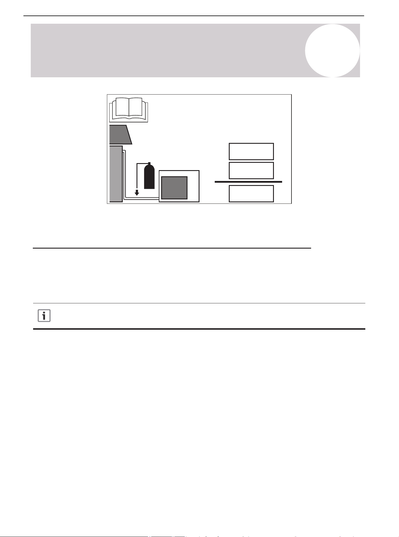
Warning: Refrigerant Oil
Attempting to repair central air-conditioning products may result in property damage, serious personal
injury, or death. These units use R-454B refrigerant, which has a working pressure that is 50-70%
higher than R-22. Use only the service equipment approved by R-454B. The refrigerant cylinder is
painted "rose" to indicate the type of refrigerant. The cylinder may contain a "dip" tube to allow liquid
refrigerant to be filled into the system. This system uses POE oil (VG74, VG75, or equivalent), which
can easily absorb moisture from the atmosphere. In order to limit the effect of the moisture absorption,
seal the system as much as possible. If the system is exposed to the atmosphere for more than 4
hours, change the compressor oil. Do not destroy the vacuum with air. Always replace the filter dryer
when opening the system for component replacement.
Warning: Hot Surface
May cause mild to severe burns. Failure to observe this caution may result in property damage or
personal injury. Do not touch the top of the compressor.
Caution: Contains Refrigerant
Failure to follow the correct procedures will lead to personal illness, injury, or serious equipment
damage. The system contains high-pressure oil and refrigerant. Before opening the system, recover
the refrigerant to release the pressure.
Note: Indoor Unit Required
The indoor unit must match with the thermal expansion valve. The model of TXV can be changed
according to the system capacity.
Note:
The manufacturer recommends installing only approved matched indoor and outdoor systems. All
of the manufacturer's split system are AHRI-rated only with TXV indoor systems. Maximum
efficiency, optimum performance, and the best overall system reliability are some of the benefits of
installing approved matched indoor and outdoor split systems.
Note: Grounding Required
Failure to check or use the correct maintenance tools may result in equipment damage or personal
injury. Reconnect all grounding devices. Ensure all parts of this product that can conduct current are
grounded. If the grounding wire, screw, strap, clip, nut, or washer used to complete the grounding
path is removed during maintenance, it must be put back in place and properly fixed.
Safety (Continued)
Air Conditioner Installation & User Manual
5
01 02 04 05 06 07 08
09 10 11 12 13 14 15 16 17 18
19 20 21 22 23 24 25 26 27 28
29 30 31 32 33 34 35 36 37 38
39 40 41 42 43 44 45 46 47 48
49
1
Safety Symbols & Instructions
Warning: Service Valve
Failure to observe this warning will result in release of system pressure, which may result in personal
injury or property damage. Use caution when opening the liquid pipeline service valve. Turn the valve
stem counterclockwise until the valve stem touches the bead.
Warning: Brazing Required
Failure to check the wiring or use the correct maintenance tools may result in equipment damage or
personal injury. If using existing refrigerant lines, ensure that all joints are brazed, not soldered.
Warning: High Current Leakage
Failure to observe this warning may result in property damage, serious personal injury, or death.
Before connecting the power supply, grounding is essential.
Warning:
This product may expose individuals to chemicals including lead and lead components, which are
known to cause cancer, birth defects, or other reproductive harm in California. For more information,
visit www.P65Warnings.ca.gov.
Warning:
• Do not use alternative methods to accelerate the defrosting or cleaning process, other than those
recommended by the manufacturer.
• The appliance is designed to be operated in an outdoor area. If installing the appliance indoors is
needed, store the appliance in a room without continuously operating open flames (an operating
gas appliance) and ignition sources (an operating electric heater).
• Do not pierce or burn.
• Be aware that refrigerants may not contain an odor.
Safety (Continued)
Air Conditioner Installation & User Manual
6
01 02 03 05 06 07 08
09 10 11 12 13 14 15 16 17 18
19 20 21 22 23 24 25 26 27 28
29 30 31 32 33 34 35 36 37 38
39 40 41 42 43 44 45 46 47 48
49
Warning
Caution
Caution
Caution
1
Safety Symbols & Instructions
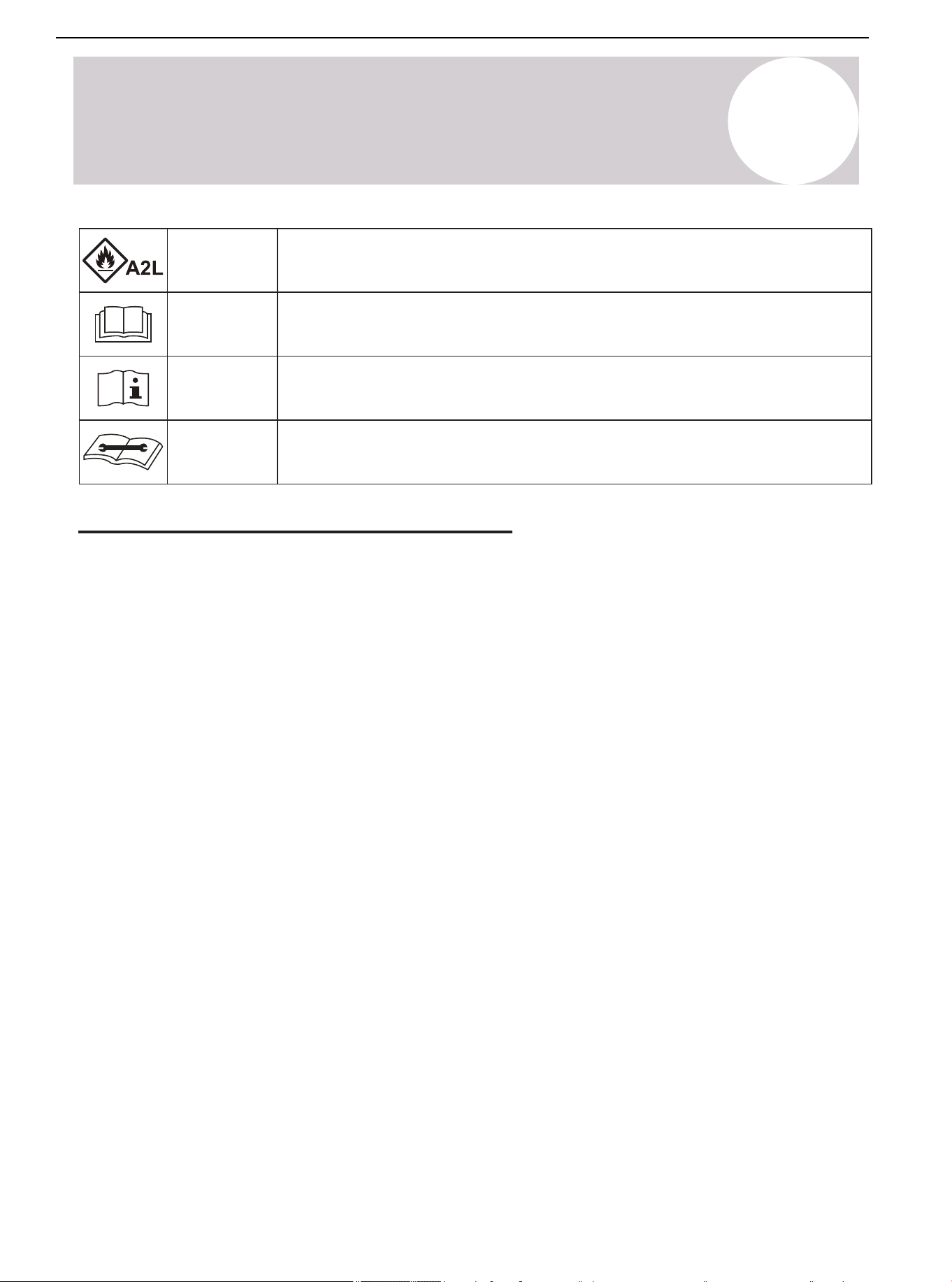
This symbol indicates that this appliance used a flammable refrigerant. If the
refrigerant is leaked and exposed to an external ignition source, there is a risk of fire.
This symbol indicates that the operation manual should be read carefully.
This symbol indicates that service personnel should be handling this equipment
with reference to the installation manual.
This symbol indicates that the information is available such as the operating or
installation manual.
Safety Precautions for R-454B Refrigerant
Warning
• Do not attempt to accelerate the defrosting process or remove frost manually.
• Store the appliance in a room free of continuously operating ignition sources (e.g., open flames, active gas
appliances, and operating electric heaters).
• Do not pierce or incinerate the appliance or its components.
• Be aware that refrigerants may be odorless.
Qualification of Workers
Competent individuals must carry out every working procedure, such as maintenance, service, and repair
operations that affect safety. Examples for these working procedures are:
• Breaking into the refrigerating circuit.
• Opening sealed components.
• Opening ventilated enclosures.
Checks to the Area
Prior to beginning work on systems containing flammable refrigerants, complete safety checks to ensure that the
risk of ignition is minimized.
Work Procedure
Conduct all work under a controlled process to minimize the risk of flammable gas or vapor from being present
during service.
General Work Area
All maintenance staff and other working in the local area must be instructed on the nature of work being carried
out. Avoid working in confined spaces.
Air Conditioner Installation & User Manual
7

01 02 03 04 06 07 08
09 10 11 12 13 14 15 16 17 18
19 20 21 22 23 24 25 26 27 28
29 30 31 32 33 34 35 36 37 38
39 40 41 42 43 44 45 46 47 48
49
1
Safety Symbols & Instructions
Checking for Presence of Refrigerant
Check the area with an appropriate refrigerant detector prior and during work, ensuring the technician is aware
of potentially toxic or flammable atmospheres. Confirm that the leak detection equipment being used is suitable
for use with all applicable refrigerants (i.e. non-sparking, adequately sealed, or intrinsically safe).
Presence of Fire Extinguisher
If conducting hot work on the refrigerating equipment or any associated parts, appropriate fire extinguishing
equipment must be available. Have a dry powder or CO
2
fire extinguisher adjacent to the charging area.
No Ignition Sources
Individuals carrying out work related to the refrigerating system that involves exposing any pipework must not
use any sources of ignition in such a manner that it may lead to a risk of fire or explosion. Keep all potential
ignition sources, including smoking, at a safe distance from the installation, repair, removal, disposal areas, and
locations where refrigerant may be released unintentionally into the surrounding space. Before commencing
work, inspect the area to ensure that no flammable hazards or ignition risks are present. Clearly display "No
Smoking" signs in the work area.
Ventilated Area
Ensure the work is conducted in either an open area or in a space with adequate ventilation before breaking
into the system or performing any heat-producing tasks. Maintain ventilation throughout the duration of the
work. Ensure the ventilation system effectively disperses any released refrigerant and directs it safely to an
external atmosphere, if possible.
Checks to the Refrigerating Equipment
When replacing electrical components, ensure that they meet the correct specifications and are suitable for their
intended purpose. Follow the manufacturer's maintenance and service guidelines. If unsure, consult the
manufacturer's technical support department for guidance.
Apply the following checks to installations using flammable refrigerants:
• Ensure that the refrigerant charge size complies with the minimum room size requirements when installing
refrigerant-containing components.
• Verify that the ventilation equipment and exhaust outlets are functioning properly and are free from
obstructions.
• If using an indirect refrigerant circuit, inspect the secondary circuit for any presence of refrigerant.
• Confirm that all equipment markings remain visible and legible. Replace or correct any illegible markings or
signs.
• Install the refrigeration piping and components in locations where they are not exposed to substances that
could cause corrosion. If exposure is unavoidable, verify that the components are either made from corrosion-
resistant materials or are adequately protected against corrosion.
Safety Precautions for R-454B Refrigerant (Continued)
Air Conditioner Installation & User Manual
8

01 02 03 04 05 07 08
09 10 11 12 13 14 15 16 17 18
19 20 21 22 23 24 25 26 27 28
29 30 31 32 33 34 35 36 37 38
39 40 41 42 43 44 45 46 47 48
49
1
Safety Symbols & Instructions
• Fully discharging the capacitors in a controlled manner to prevent sparking.
• Verifying that no live electrical components or exposed wiring are present during system charging, refrigerant
recovery, or purging.
• Confirming that the earth bonding continuity is maintained.
Repairs to Sealed Components
Replace sealed electrical components, rather than repair them.
Repairs to Intrinsically Safe Components
Replace intrinsically safe components, rather than repair them.
Cabling
Do not expose the cabling to wear, corrosion, excessive pressure, vibration, sharp edges, or other adverse
environmental factors. Consider the long-term effects of aging and continuous vibration from components such
as compressors or fans.
Detection of Flammable Refrigerants
Do not use potential sources of ignition for refrigerant leak detection under any circumstances. Do not use a
halide torch or any other detector using a naked flame.
The following methods are approved for detecting leaks in systems containing flammable refrigerants:
-- Electronic Leak Detectors: Use this method for detecting flammable refrigerants. Note: They may require
recalibration to maintain adequate sensitivity.
• Calibrate the detection equipment in a refrigerant-free area.
• Ensure that the detector does not pose an ignition risk and is compatible with the refrigerant in use.
• Set the detector to a percentage of the refrigerant's Lower Flammability Limit (LFL). In addition, calibrate the
detector to confirm that the appropriate gas concentration does not exceed 25% of the LFL.
-- Leak Detection Fluids: This method is suitable for most refrigerants but must not contain chlorine.
Note: Chlorine can react with the refrigerant and corrode copper piping. If a leak is suspected, remove or
extinguish all open flames. If a refrigerant leak requiring brazing is detected, fully recover the refrigerant or
isolate the refrigerant using the shut-off valves to prevent accidental release. The removal of refrigerant must
be in accordance with Removal & Evacuation.
Safety Precautions for R-454B Refrigerant (Continued)
Checks to Electrical Devices
Ensure the repair and maintenance of electrical components include initial safety checks and a thorough
inspection of components. If the fault cannot be corrected immediately but continuing work is necessary,
implement a temporary solution that is safe and effective. Report any temporary measures to the equipment
owner, ensuring all relevant parties are informed.
Initial safety checks must include:
Air Conditioner Installation & User Manual
9

1
Safety Symbols & Instructions
Removal & Evacuation
Use conventional procedures when breaking into the refrigerant circuit to make repairs, etc. For flammable
refrigerants, follow this procedure for best practices:
• Safely remove refrigerant following local and national regulations.
• Evacuate.
• Purge the circuit with inert gas (optional for A2L).
• Evacuate (optional for A2L).
• Continuously flush or purge with inert gas when using a flame to open the circuit.
• Open the circuit.
Recover the refrigerant charge into the correct recovery cylinders if venting is not allowed due to local and
national codes. For appliances containing flammable refrigerants, purge the system with oxygen-free nitrogen to
render the appliance safe for flammable refrigerants. This process might need to be repeated several times. Do
not use compressed air oxygen for purging refrigerant systems.
For appliances containing flammable refrigerants, purge the refrigerants by breaking the vacuum in the system
with oxygen-free nitrogen and continuing to fill until the working pressure is achieved. Vent the system to
atmosphere and finally pull down to a vacuum (optional for A2L). Repeat this process until no refrigerant is within
the system (optional for A2L). When the final oxygen-free nitrogen is used, vent the system down to atmospheric
pressure to enable work to take place.
Keep the outlet for the vacuum pump away from any potential ignition sources and ensure ventilation is
available.
Charging Procedures
In addition to conventional charging procedures, follow these requirements:
• Ensure that the contamination of different refrigerants does not occur when using charging equipment. Hoses
or lines must be as short as possible to minimize the amount of refrigerant contained in them.
• Cylinders must be kept in an appropriate position according to the instructions.
• Ensure that the refrigerating system is earthed prior to charging the system with refrigerant.
• Label the system when charging is complete (if not already).
• Extreme care must be taken to not overfill the refrigerating system
Prior to recharging the system, it must be pressure-tested with the appropriate purging gas. The system must be
leak-checked after completing the charging but prior to commissioning. Complete a follow up leak test prior to
leaving the site.
Safety Precautions for R-454B Refrigerant (Continued)
Air Conditioner Installation & User Manual
10

01 02 03 04 05 06 08
09 10 11 12 13 14 15 16 17 18
19 20 21 22 23 24 25 26 27 28
29 30 31 32 33 34 35 36 37 38
39 40 41 42 43 44 45 46 47 48
49
1
Safety Symbols & Instructions
Decommissioning
Before carrying out this procedure, ensure the technician is completely familiar with the equipment and its
details. It is recommended good practice to safely recover all refrigerants. Prior to carrying out the task, an oil
and refrigerant sample must be taken in case analysis is required. Confirm that electrical power is available
before commencing the task.
A. Become familiar with the equipment and its operation.
B. Isolate the system electrically.
C. Before attempting the procedure, ensure that:
• Mechanical handling equipment is available for handling refrigerant cylinders (if required).
• All personal protective equipment (PPE) is available and being used correctly.
• A competent person supervises the recovery process at all times.
• Recovery equipment and cylinders conform to the appropriate standards.
D. Pump down the refrigerant system, if possible.
E. If a vacuum is not possible, make a manifold so that refrigerant can be removed from various parts of the
system.
F. Ensure that the cylinder is situated on the scales before recovery takes place.
G. Start the recovery machine and operate it in accordance with the instructions.
H. Do not overfill cylinders (no more than 80% volume liquid charge).
I. Do not exceed the maximum working pressure of the cylinder, even temporarily.
J. When the cylinders have been filled correctly and the process is completed, ensure that the cylinders and
equipment are removed from the site promptly, as well as all isolation valves on the equipment are closed off.
K. Do not charge recovered refrigerant into another system unless it has been cleaned and checked.
Safety Precautions for R-454B Refrigerant (Continued)
Air Conditioner Installation & User Manual
11

01 02 03 04 05 06 07
09 10 11 12 13 14 15 16 17 18
19 20 21 22 23 24 25 26 27 28
29 30 31 32 33 34 35 36 37 38
39 40 41 42 43 44 45 46 47 48
49
1
Safety Symbols & Instructions
Labeling
Label the equipment stating that it has been decommissioned and emptied of refrigerant. The label must be
dated and signed. For appliances containing flammable refrigerants, label the equipment stating the equipment
contains flammable refrigerant.
Recovery
When removing refrigerant from a system for service or decommissioning, safely remove all the refrigerant.
When transferring refrigerant into cylinders, only employ appropriate refrigerant recovery cylinders. Ensure that
the correct number of cylinders for holding the system charge are available. All cylinders that are used must be
designated for the recovered refrigerant and labeled for that refrigerant (i.e. special cylinders for the recovery of
refrigerant). Cylinders must be complete with functioning pressure-relief valves and associated shut-off valves.
Evacuate empty recovery cylinders and allow them to cool before recovery occurs, if possible.
The recovery equipment must be in good working order with a set of instructions concerning the equipment that
is at hand. The equipment must be suitable for the recovery of the flammable refrigerant. If in doubt, consult the
manufacturer. In addition, a set of calibrated weighing scales must be available and in good working condition.
Process the recovered refrigerant according to the local legislation in the correct recovery cylinder. Arrange a
relevant waste transfer note. Do not mix refrigerants in recovery units and especially not in cylinders.
If removing compressors or compressor oils, evacuate them to an acceptable level, ensuring that the flammable
refrigerant does not remain within the lubricant. Do not heat the compressor body with an open flame or other
ignition sources to accelerate this process. When oil is drained from the system, it must be carried out safely.
Safety Precautions for R-454B Refrigerant (Continued)
Air Conditioner Installation & User Manual
12
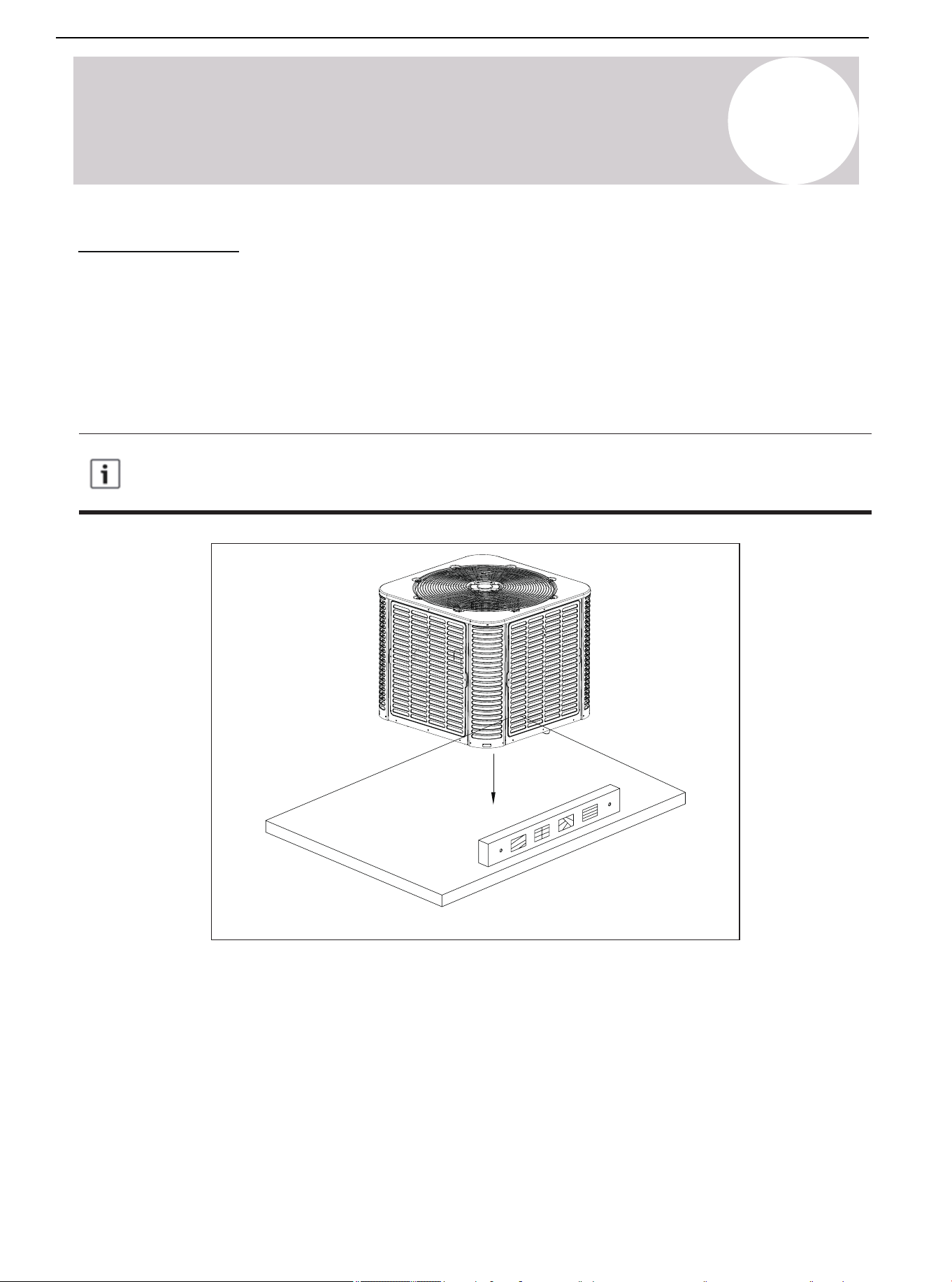
2
Considerations for Unit Location
Model
Cooling
Heating
Temperature
5-125°F (-15-52°C)
-4-86°F (-20-30°C)
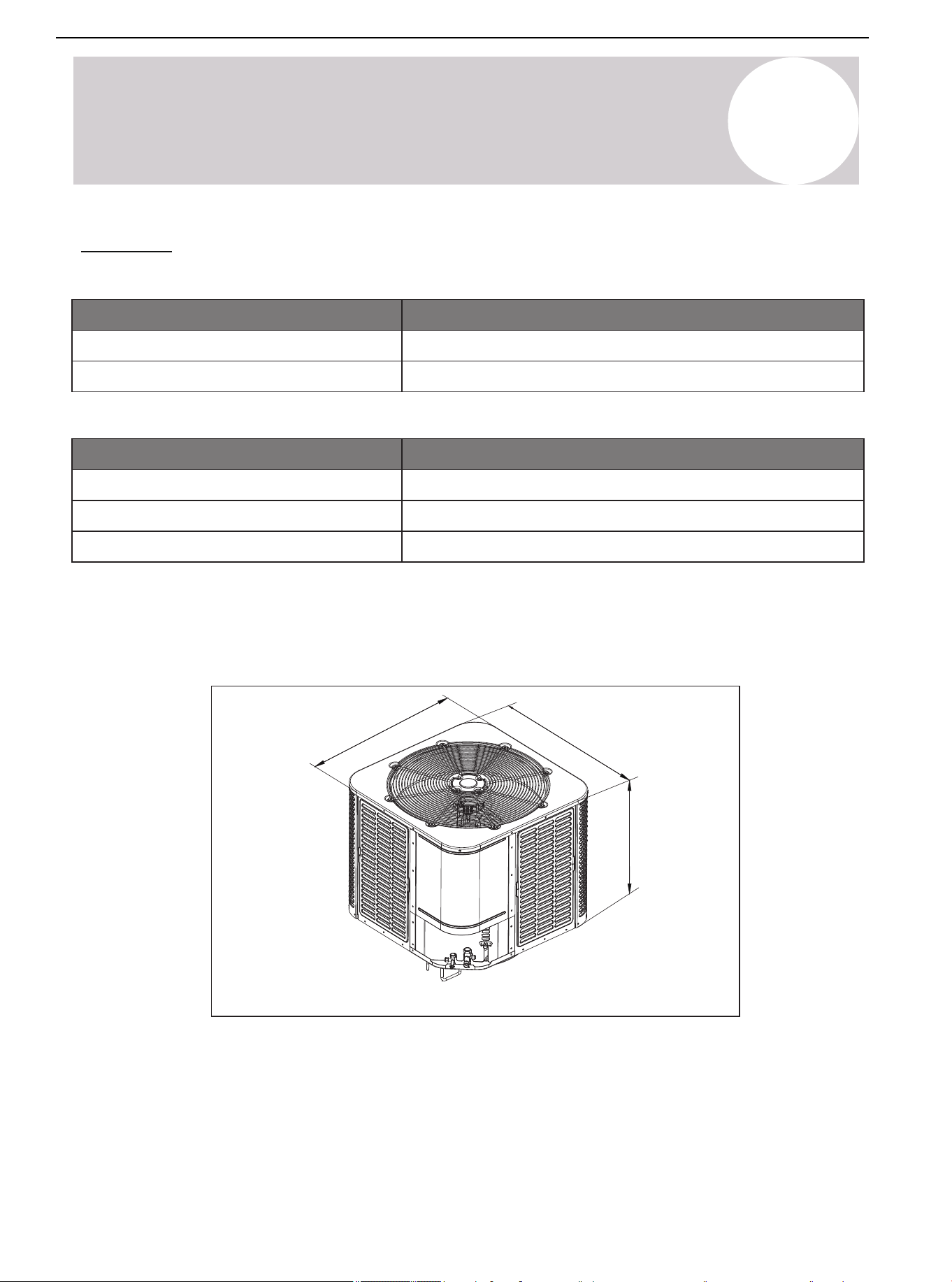
Unit Size
Model
24/36K
48/60K
W x D x H Inches [mm]
29-½ x 29-½ x 25 [749 x 749 x 635]
29-½ x 29-½ x 32-⅞ [749 x 749 x 835]
Table 2.2. Outdoor Unit Dimensions
Unit Size
Table 2.1. Outdoor Operating Temperature
The weight of the unit is also printed on the carton.
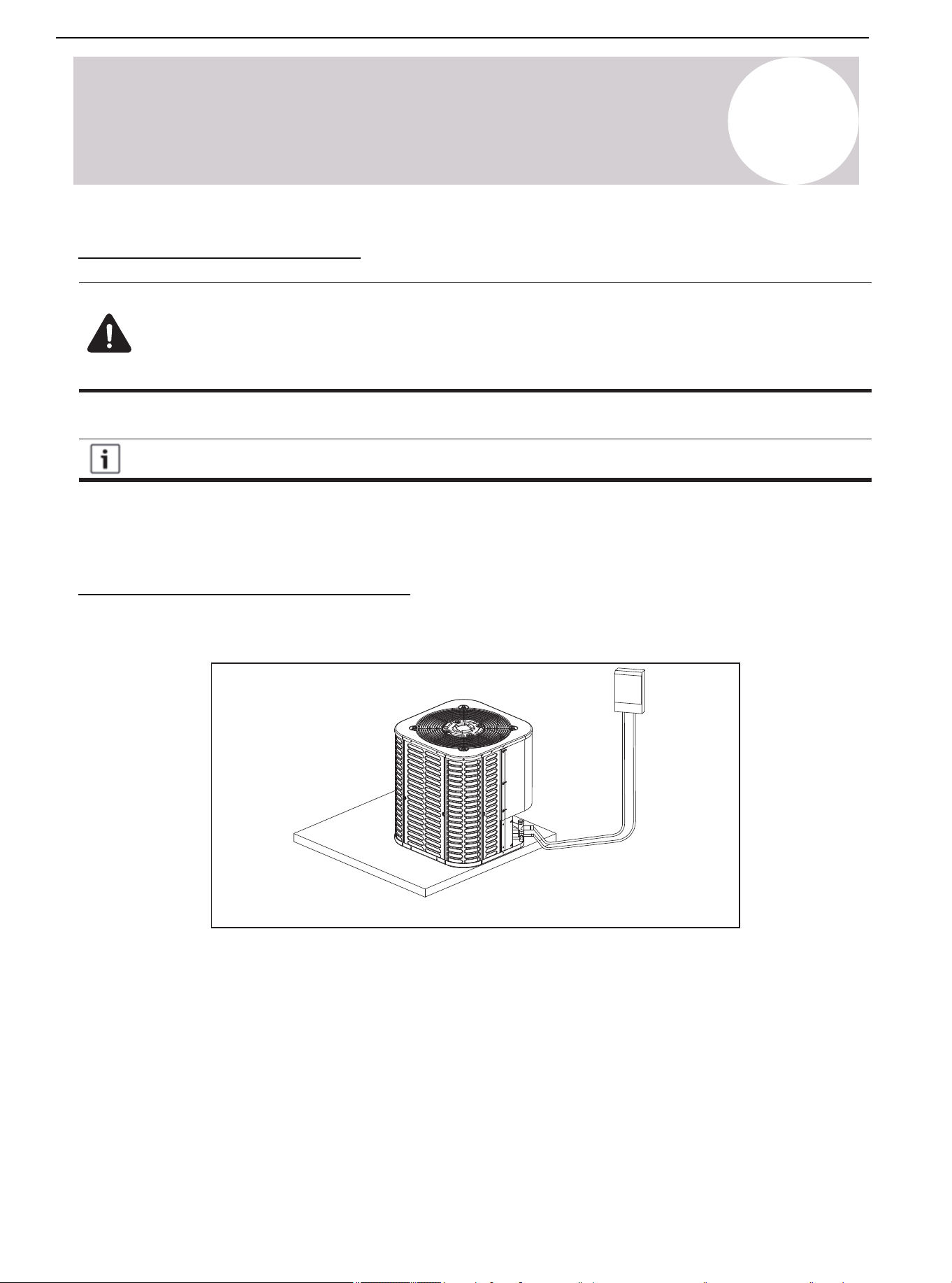
When installing the outdoor unit on the roof, ensure that the roof can support the weight of the outdoor unit.
Choosing an appropriate isolation is recommended to prevent sound or vibration from being transmitted to the
building structure.
Figure 2.1.
D
W
H
Air Conditioner Installation & User Manual
13
01 02 03 04 05 06 07 08
10 11 12 13 14 15 16 17 18
19 20 21 22 23 24 25 26 27 28
29 30 31 32 33 34 35 36 37 38
39 40 41 42 43 44 45 46 47 48
49
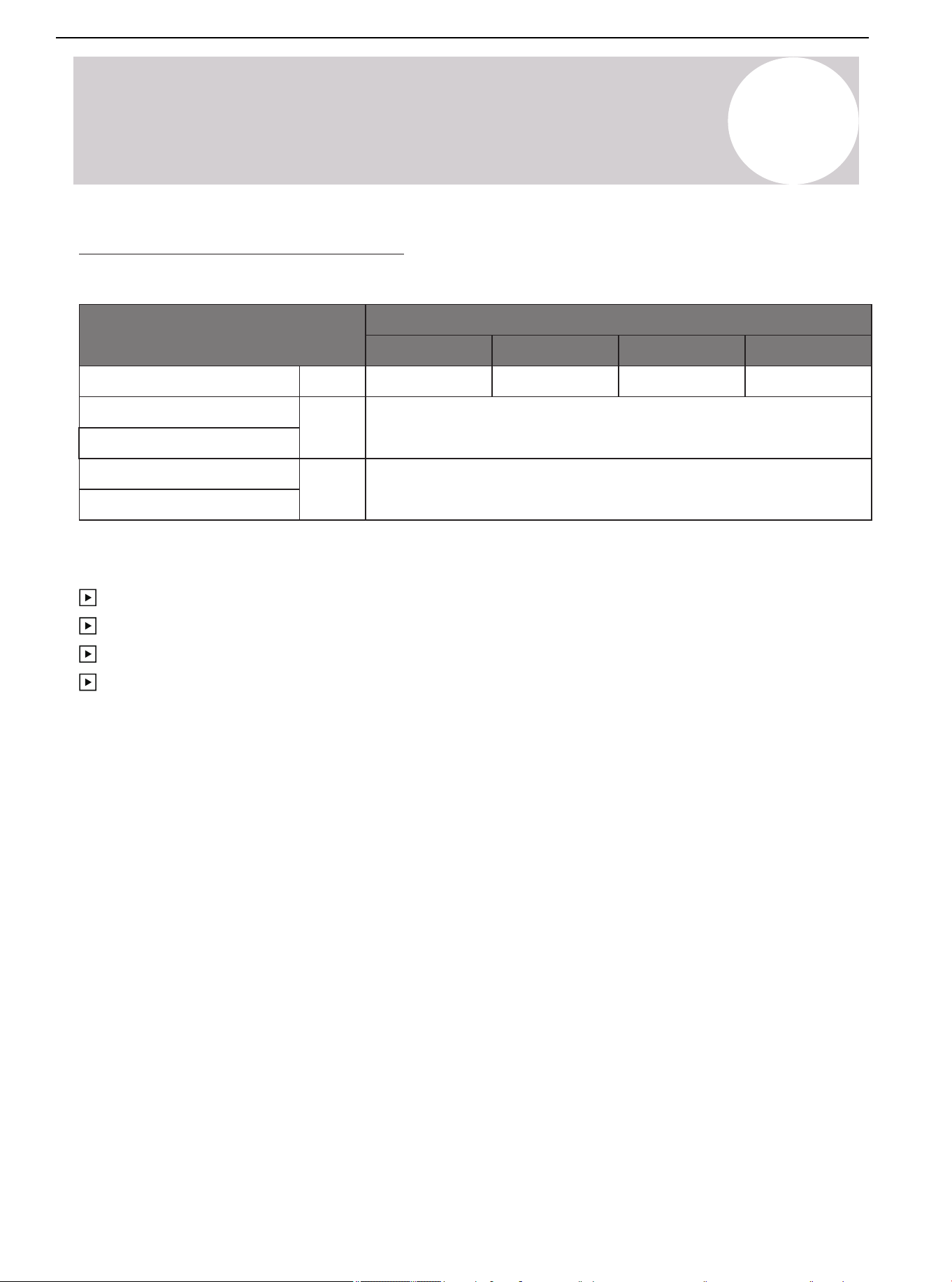
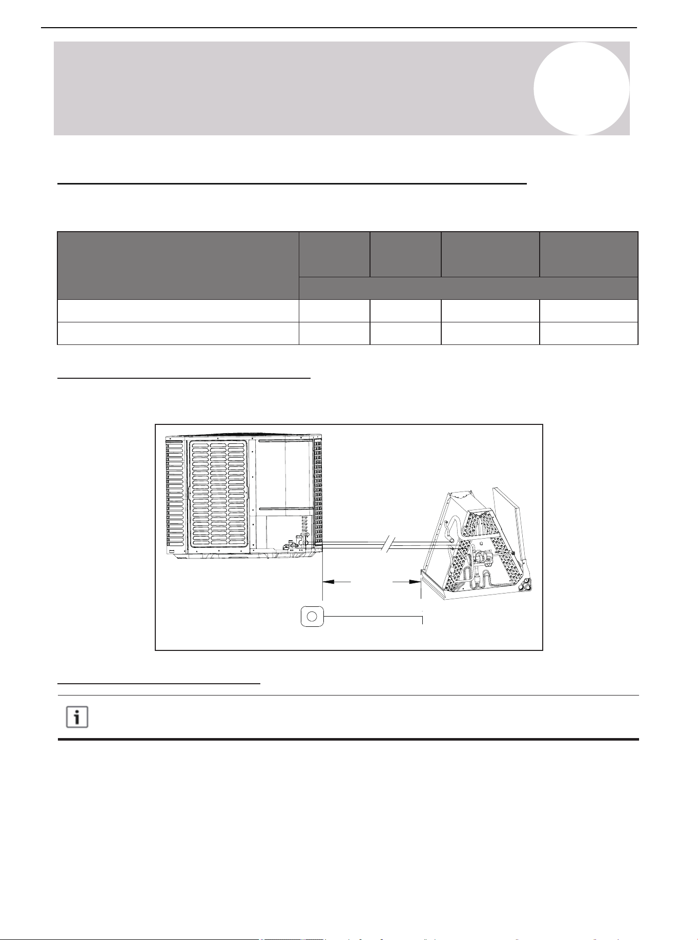
Refrigerant Pipeline Restriction
Table 2.3.
* It is recommended to adopt standard pipeline size; Refrigerant charge: see page.
Refrigerant Line
Liquid Suction
Max. Refrigerant
Line Length*
Max. Elevation*
Vertical Lift*
in.
ft.
ft.
Capacity (Kbtu/h)
24K
36K 48K
100
60K
⅜-¾ ⅜-¾ ⅜-⅞
50
⅜-⅞
2
Considerations for Unit Location
Maximum equivalent length of pipeline = 100 feet (30.5 m).
Maximum vertical equivalent length = 50 feet (15 m).
Use only the pipe diameters shown in Table 2.3.
If the suction line exceeds 65 feet (20 m), do not use a larger suction line than recommended.
Air Conditioner Installation & User Manual
14
01 02 03 04 05 06 07 08
09
11 12 13 14 15 16 17 18
19 20 21 22 23 24 25 26 27 28
29 30 31 32 33 34 35 36 37 38
39 40 41 42 43 44 45 46 47 48
49
Figure 2.2.
Standard lineset
100 ft. (30.5 m)
Max line length
50 ft. (15 m)
Max line lift
2
Considerations for Unit Location
50 ft. (15 m)
Max line lift
Air Conditioner Installation & User Manual
15
2
Considerations for Unit Location
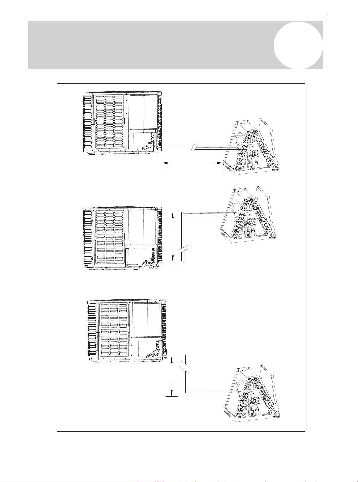
Long Line Installation Precautions
• The length of the connecting line from the outdoor unit to the indoor unit cannot exceed 100 feet (30.5 m).
• If all long lines are in a horizontal state, no additional measures are required.
• If there is a vertical height difference in the long line, install it according to the following requirements:
-- When the vertical height difference is 0 < h ≤ 16.5 ft (5 m), no additional measurements are required.
-- When the vertical height difference is (5 m) 16.5 ft < h ≤ 33 ft (10 m), add an oil return trap in the middle of the
height difference.
-- When the vertical height difference is (10 m) 33 ft < h ≤ 50 ft (15 m), add two oil return traps at an equal
distance in the height difference.
Note: The vertical height difference between the outdoor unit and indoor unit cannot exceed 50 feet (15 m). The
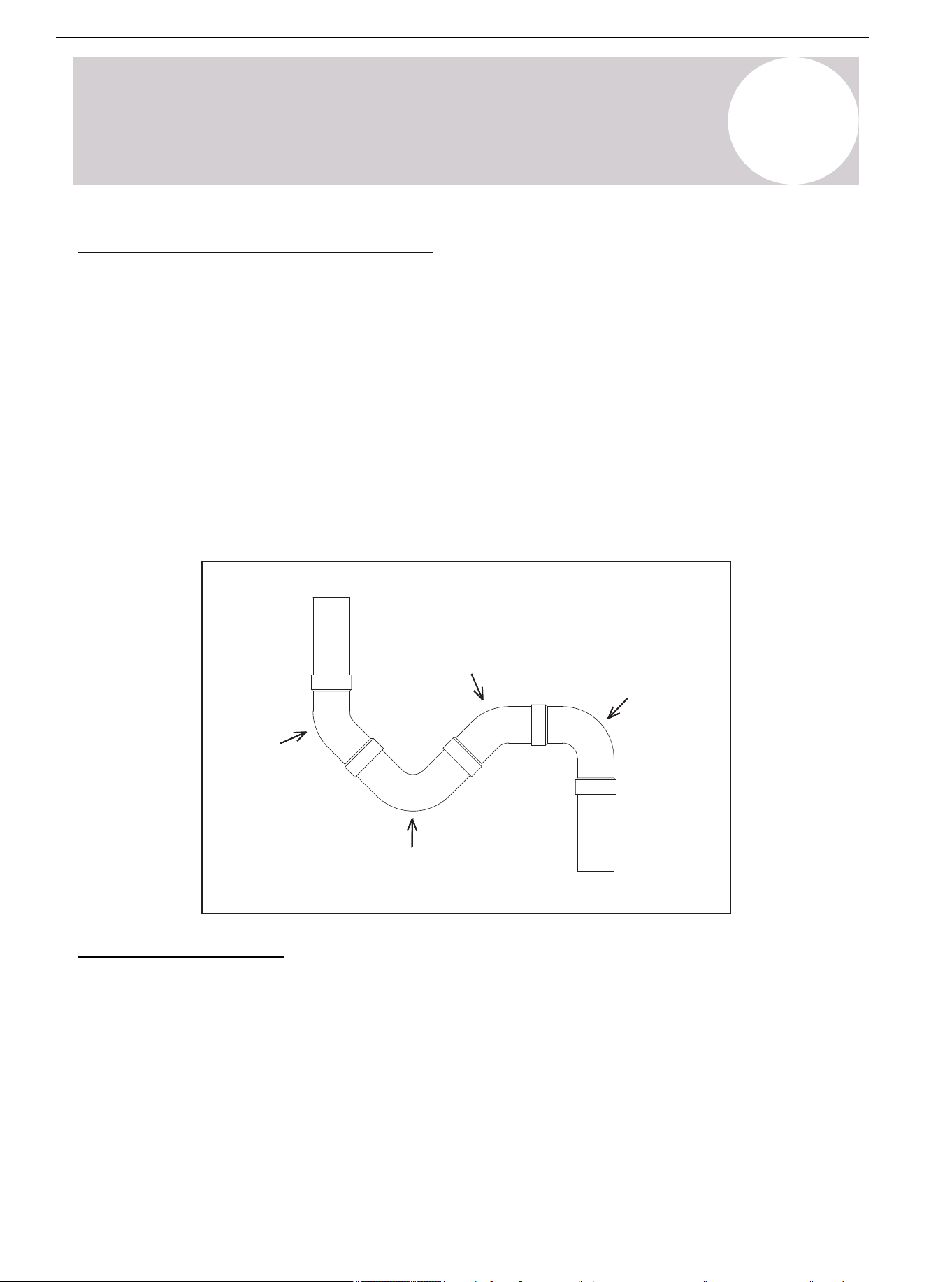
following is the connection method of the oil return trap:
45° Elbow 1
45° Elbow 3
90° Elbow 2
90° Elbow 4
Oil trap structure
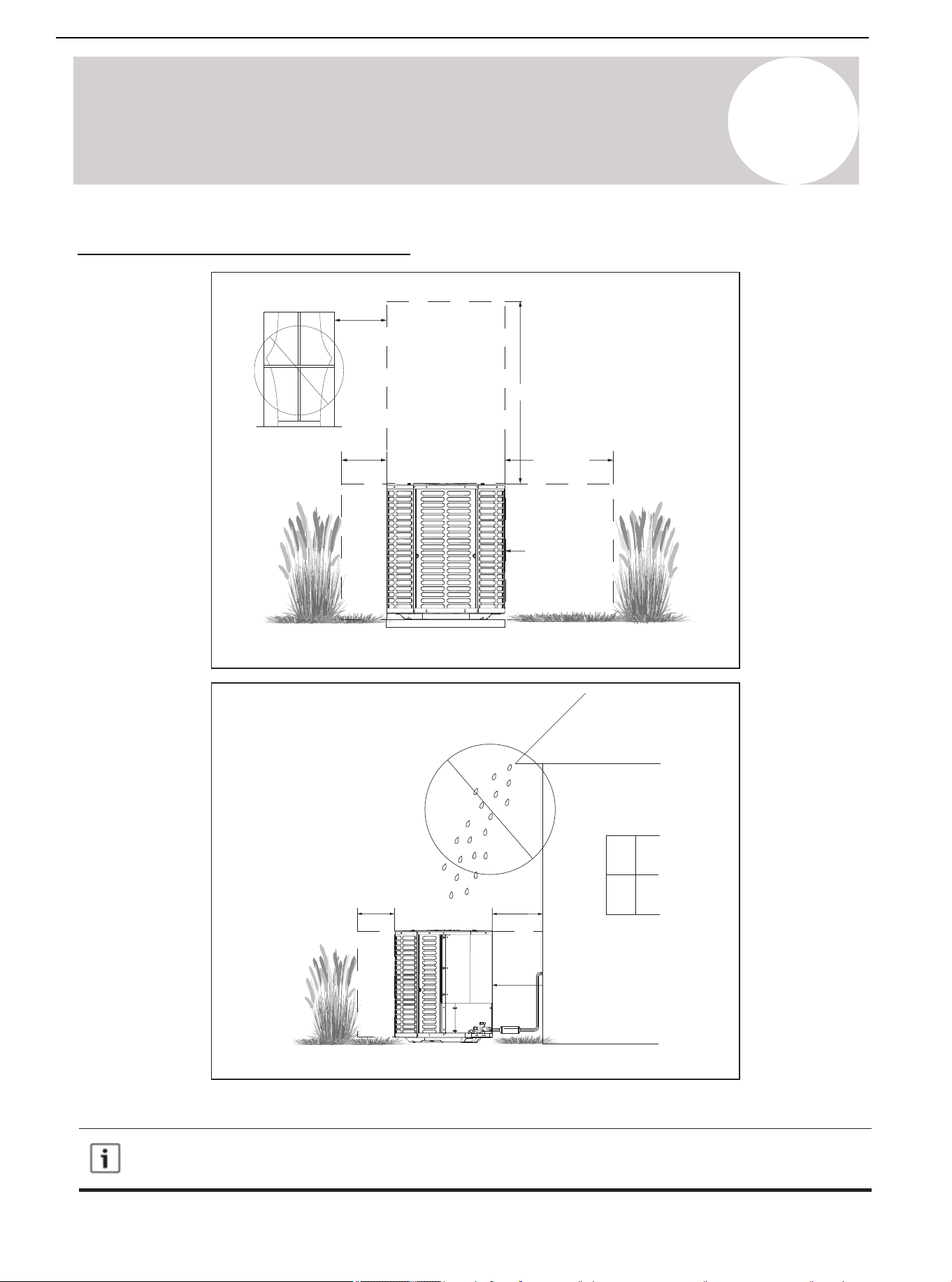
Position Restriction
• Ensure that the discharge area is unrestricted (at least 60 inches / 1,524 mm above the top of the unit).
• Do not put the outdoor unit near the bedroom, because the normal operating sound may be audible.
• Position the equipment leaving enough space for smooth airflow, wiring, refrigerant lines, and maintainability.
• Allow a minimum of 12 inches (305 mm) clearance on one side of the control board access panel to a wall,
as well as a minimum 24 inches (610 mm) on the adjacent side of the control board access panel.
• Maintain a distance of 24 inches (610 mm) between the adjacent units.
• Place the unit in a location where water, snow, or ice cannot fall directly on the device from the roof of
overhangs.
• See Figures 2.3. and 2.4.
Air Conditioner Installation & User Manual
16
01 02 03 04 05 06 07 08
09 10 11
13 14 15 16 17 18
19 20 21 22 23 24 25 26 27 28
29 30 31 32 33 34 35 36 37 38
39 40 41 42 43 44 45 46 47 48
49
Figure 2.3.
Figure 2.4.
Avoid installations
near bedrooms
Min.12 inch (305 mm)
to shrubbery
Min. 60 inch (1,524 mm) unrestricted
Min. 24 inch
(610 mm)
unrestricted
Access panel
Access panel
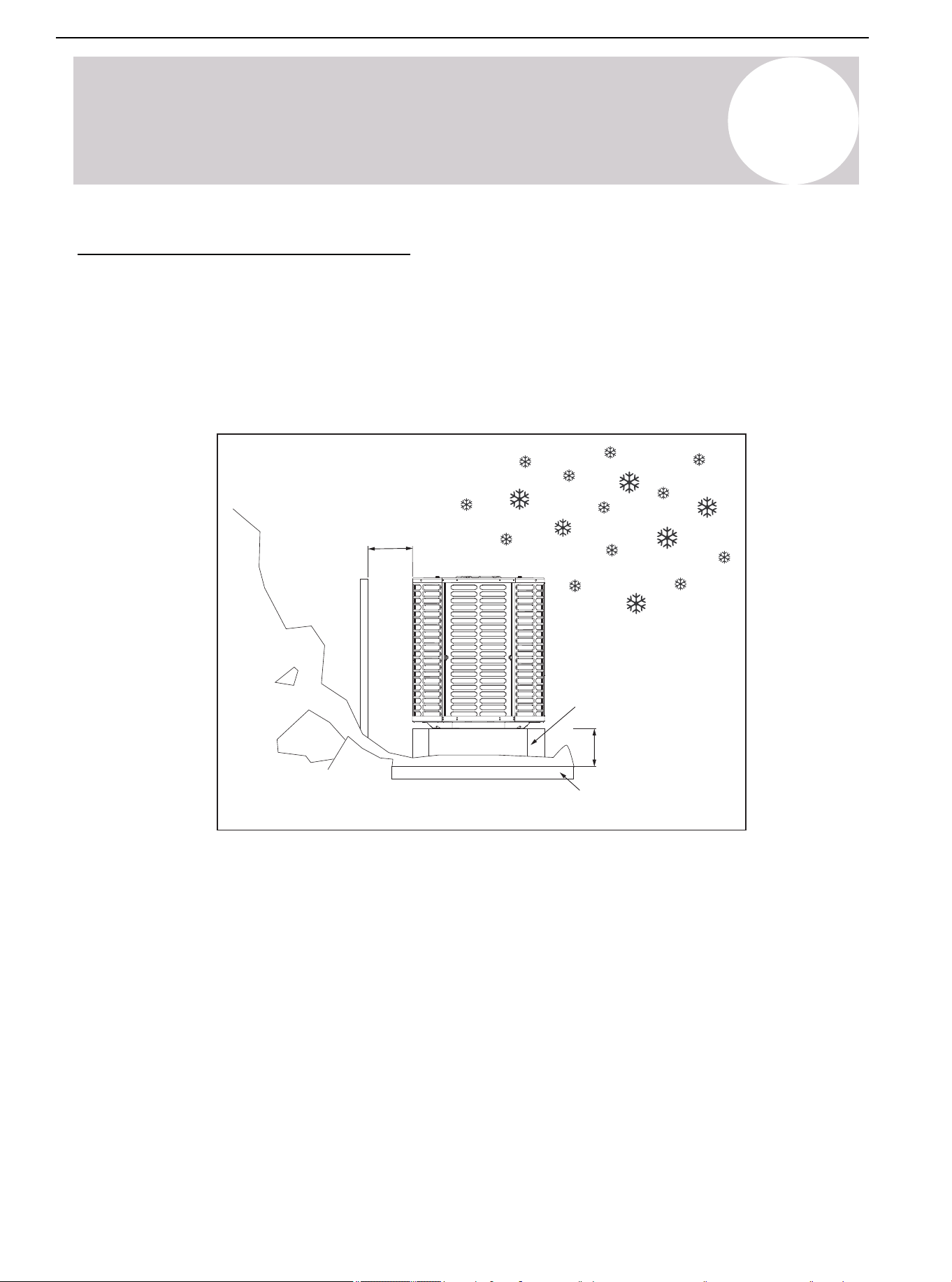
Precautions must be taken for units installed in areas with snow and long-term temperatures below
freezing point.
Precautions in cold climate (heat pump only)
2
Considerations for Unit Location
Min.12 inch (305 mm)
to
shrubbery
Min. 24 inch
(610 mm)
unrestricted
Position Restriction (Continued)
Air Conditioner Installation & User Manual
17
01 02 03 04 05 06 07 08
09 10 11 12
14 15 16 17 18
19 20 21 22 23 24 25 26 27 28
29 30 31 32 33 34 35 36 37 38
39 40 41 42 43 44 45 46 47 48
49
Figure 2.5.
Snow
barrier
Min.12 inch (305 mm)
Snow legs
3-12 inch (76-305 mm)
Elevation
Pad
2
Considerations for Unit Location
• Depending on the local weather conditions, raise the unit by 3-12 inches (76-305 mm). This extra height will
allow the snow and ice melted during the defrosting cycle to be discharged before refreezing. Ensure that the
drain hole on the unit chassis is not blocked, otherwise it will hinder the defrosting water discharge (See
Figure 2.5.).
• If possible, avoid locations that are prone to snow. If this is not possible, install a snow barrier around the unit
to prevent snow accumulation on the side of the unit.
Corrosive Environment
Exposure to a corrosive environment may shorten the service life of the unit, corrode metal parts, and negatively
affect the performance of the unit. Corrosive elements include but are not limited to:
• Sodium
• Chloride
• Sodium hydroxide
• Sodium sulfate
• Compounds commonly found in seawater
• Sulfur
• Chlorine
• Fluorine
• Fertilizers
• Various chemical pollutants from industrial / manufacturing plants
Position Restriction (Continued)
Air Conditioner Installation & User Manual
18

2
Considerations for Unit Location
If it is installed in an area that may be exposed to corrosive environment, pay special attention to the placement
and maintenance of the unit.
• Ensure that lawn sprinklers / hoses / waste water does not spray directly on the outer panel of the unit for a
long duration of time.
• In coastal areas: Install the unit on the side away from the waterfront.
• Fences or shrubs can provide some shielding protection for the unit. Maintain the minimum device clearance.
• Clean the outdoor coil and any exposed external surfaces about every 3 months.
Position Restriction (Continued)
Air Conditioner Installation & User Manual
19
01 02 03 04 05 06 07 08
09 10 11 12 13
15 16 17 18
19 20 21 22 23 24 25 26 27 28
29 30 31 32 33 34 35 36 37 38
39 40 41 42 43 44 45 46 47 48
49
Figure 3.1.
3
Unit Installation Preparation
Prepare the Unit for Installation
• Check whether there is any damage to unit. Report any damage to the courier. (Figure 3.1.).
• Use the service port to ensure that the refrigerant charge is uncompromised during shipment.
Air Conditioner Installation & User Manual
20
01 02 03 04 05 06 07 08
09 10 11 12 13 14
16 17 18
19 20 21 22 23 24 25 26 27 28
29 30 31 32 33 34 35 36 37 38
39 40 41 42 43 44 45 46 47 48
49
Figure 4.1.
4
Unit Settings
Pad Installation
When installing the unit on a support pad (such as a concrete slab), consider the following:
• All sides of the pad must be at least 1-2 inches (25-51 mm) larger than the unit.
• Separate the pad from any structure.
• The pad must be level.
• Ensure that the pad is high enough above the ground for drainage.
• The location of the pad must comply with national, state, and local regulations.
This procedure outlines how to fix the system to a cement slab in windy areas. Check the local
regulations of tie-down methods and protocols.
Air Conditioner Installation & User Manual
21
01 02 03 04 05 06 07 08
09 10 11 12 13 14 15
17 18
19 20 21 22 23 24 25 26 27 28
29 30 31 32 33 34 35 36 37 38
39 40 41 42 43 44 45 46 47 48
49
Model
24K/36K
48K/60K
Table 5.1.
Figure 5.1.
Suction Line Liquid Line
Suction Line
Connection
Liquid Line
Connection
Dimensions Inches [mm]
¾ [19] ⅜ [9.5] ¾ [19]
⅞ [22]
Line length
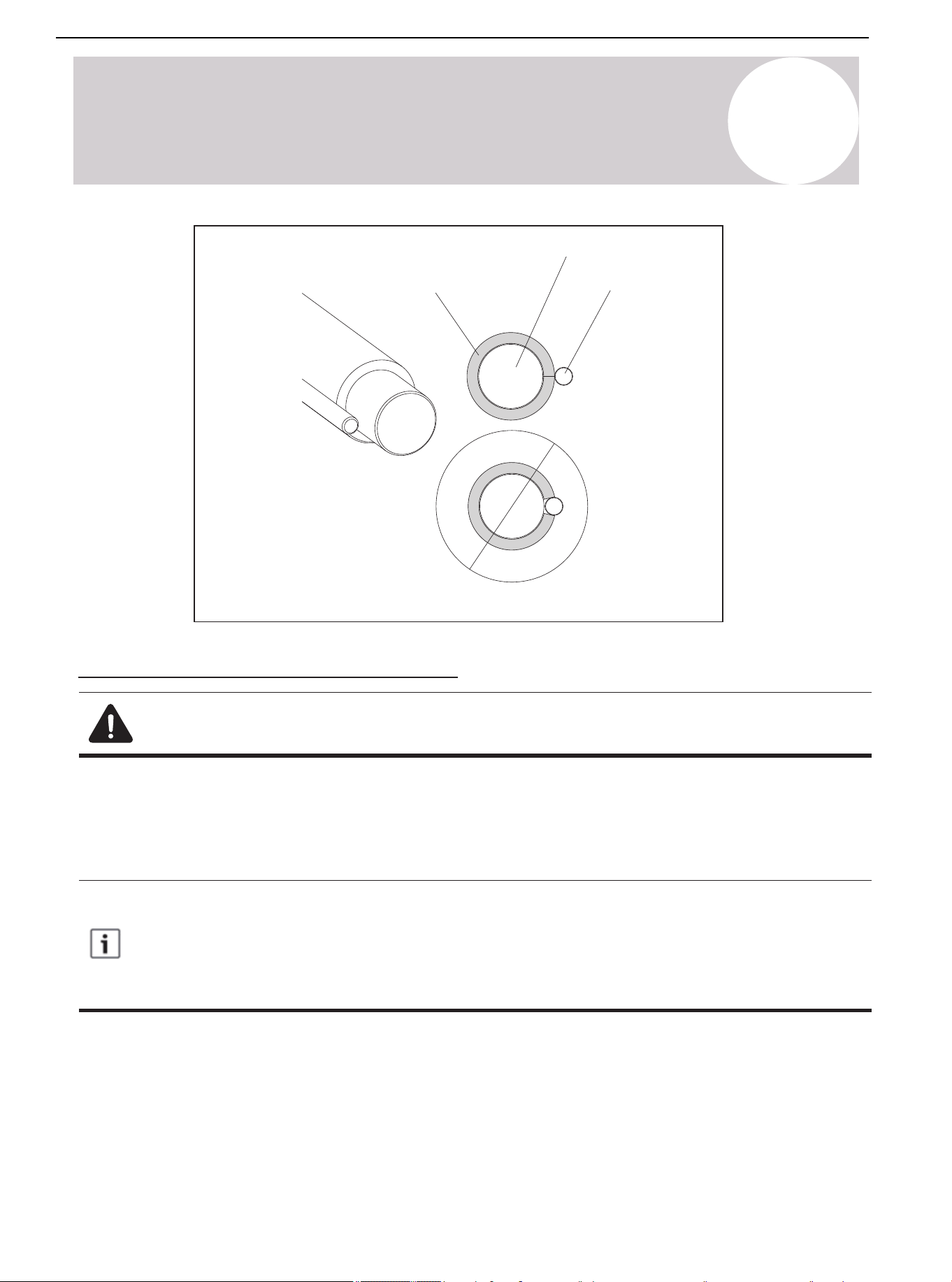
5
Precautions for Refrigerant Pipeline
Connecting Dimensions of Refrigerant Lines & Service Valves
⅜ [9.5] ⅜ [9.5]
⅜ [9.5]
⅞ [22]
Required Refrigerant Line Length
Determine the required pipeline length (See Figure 5.1.)
Refrigerant Pipe Insulation
Always insulate the refrigerant pipe. Do not allow the liquid line and suction line come into direct contact
(metal to metal).
Air Conditioner Installation & User Manual
22
01 02 03 04 05 06 07 08
09 10 11 12 13 14 15 16
18
19 20 21 22 23 24 25 26 27 28
29 30 31 32 33 34 35 36 37 38
39 40 41 42 43 44 45 46 47 48
49
Figure 5.2.
Liquid line
Suction line
Insulation
5
Precautions for Refrigerant Pipeline
Reuse the Existing Refrigerant Lines
Note: Mild to Moderate Burns
If using existing refrigerant lines, ensure that all joints are brazed, not soldered.
Take the following precautions for the retrofit application that will use the existing refrigerant pipeline:
• Ensure that the refrigerant line size is correct. Refer to Table 2.2.
• Ensure that the refrigerant line is free of leakage, acid, and oil.
The manufacturer recommends only installing approved matching indoor and outdoor systems. All split
systems of the manufacturer are AHRI-rated, only applicable to indoor units with TXV. Maximum
efficiency, best performance, and best overall system reliability are benefits of installing an approved
indoor and outdoor split system.
Air Conditioner Installation & User Manual
23
6
Refrigerant Pipeline Routing
Preventive Measure
Take preventive measures to prevent noise generated by vibration transmission of the refrigerant
line in the building structure. For example:
• When the refrigerant line must be fixed on floor joists or other frames in the structure, use isolated
hangers.
• When the refrigerant line runs in the column space or closed ceiling, use isolation hangers.
• When refrigerant lines pass through walls or windowsills, ensure that they are insulated and
isolated.
• Isolate the line from all ductwork systems.
• Try to reduce the number of 90° turns.
Comply with national, state, and local regulations when isolating the wire group from joists, rafters,
walls, or other structural elements.
Air Conditioner Installation & User Manual
24
6
Refrigerant Pipeline Routing
Secure the suction line from joists using isolators every 8 feet (2.4 m). Secure the liquid line
directly to suction line using tape, wire, or other appropriate methods every 8 feet (2.4 m).
Isolated from Beam/Rafter
Figure 6.1.
Up to 8 ft. (2.4 m)
Up to 8 ft. (2.4 m)
Side view
Beam/rafter
Isolator
Lineset
Up to 8 ft. (2.4 m)
Up to 8 ft. (2.4 m)
Side view
Wall
Isolator
Lineset
Secure the suction line from joists using isolators every 8 feet (2.4 m). Secure the liquid line
directly to suction line using tape, wire, or other appropriate method severy 8 feet (2.4 m).
Isolation on the Wall
Figure 6.2.
Air Conditioner Installation & User Manual
25
01 02 03 04 05 06 07 08
09 10 11 12 13 14 15 16 17 18
20 21 22 23 24 25 26 27 28
29 30 31 32 33 34 35 36 37 38
39 40 41 42 43 44 45 46 47 48
49
Figure 6.4.
Wall
Sealant
Insulate
Suction line
Ductwork
Sound dampener
Lineset
Wall Isolation
Do not hang the lineset on the duct work.
Figure 6.3.
To indoor coil
Liquid line
PVC conduit
Insulated suction line
To outdoor unit
Cap
6
Refrigerant Pipeline Routing
Air Conditioner Installation & User Manual
26
7
Refrigerant Line Brazing
Brazed Refrigerant Pipeline
1. Remove the cover or plug. Use the deburring tool to deburr the line end. Clean the inner and outer surfaces of
the pipeline with an emery cloth.
Figure 7.1.
2. Remove the pressure taps from the two service valves.
Figure 7.2.
3. Purge refrigerant lines and indoor coils with dry nitrogen.
Figure 7.3.
This pipe must
have a thimble
Air Conditioner Installation & User Manual
27
01 02 03 04 05 06 07 08
09 10 11 12 13 14 15 16 17 18
19
21 22 23 24 25 26 27 28
29 30 31 32 33 34 35 36 37 38
39 40 41 42 43 44 45 46 47 48
49
7
Refrigerant Line Brazing
4. Wrap the valve body with a wet rage to avoid thermal damage and continue the dry nitrogen purging (See
Figure 7.4.).
Braze the refrigerant line to the service valve.
Braze the filter dryer to the liquid line.
Figure 7.4.
Figure 7.5.
Packaging and shipment of
on-site installation
3-4 in (76-102 mm)
from the valve
All units are recommended to have a bidirectional filter driver installed. Braze the filter dryer to the
liquid line, taking care not to push the refrigerant line too hard through the stopper in the filter dryer
(this may damage the filter).
Continue the dry nitrogen purge. Do not take off the wet rage before all brazing is completed.
Before stopping the dry nitrogen purge, remove the wet rag.
5. After the service valve cools down, put back the pressure tap.
Air Conditioner Installation & User Manual
28

01 02 03 04 05 06 07 08
09 10 11 12 13 14 15 16 17 18
19 20 21
23 24 25 26 27 28
29 30 31 32 33 34 35 36 37 38
39 40 41 42 43 44 45 46 47 48
49
Figure 8.1.
Figure 8.2.
250 PSIG*
8
Refrigerant Line Leakage Inspection
Check for Leaks
1. Use dry nitrogen to pressurize the refrigerant line and evaporator coil to 250 PSIG*.
2. Use soapy water or bubbles at each brazing position to check for leaks.
* Note:
After completing the field piping for split systems, pressure test the field pipework with an inert gas. Then
vacuum test the field piping prior to refrigerant charging. The minimum test pressure for the system must be the
low side design pressure. See the nameplate for details.
Air Conditioner Installation & User Manual
29
01 02 03 04 05 06 07 08
09 10 11 12 13 14 15 16 17 18
19 20 21 22
24 25 26 27 28
29 30 31 32 33 34 35 36 37 38
39 40 41 42 43 44 45 46 47 48
49
Figure 9.1.
Figure 9.2.
9
Vacuuming
Drain Refrigerant Lines & Indoor Coils
Do not open the service valve until the leakage inspection and vacuuming of refrigerant lines and
indoor coils are completed.
1. Evacuate until the micron gauge reads no higher than 350 microns, then close the valve to the vacuum pump.
2. Observe the micron gauge. If the micrometer does not rise above 500 microns within 1 minute, the evacuation
is completed.
After the evacuation, turn off the vacuum pump and micron gauge. Then close the valve on the manifold
instrument cluster.
Air Conditioner Installation & User Manual
30
01 02 03 04 05 06 07 08
09 10 11 12 13 14 15 16 17 18
19 20 21 22 23
25 26 27 28
29 30 31 32 33 34 35 36 37 38
39 40 41 42 43 44 45 46 47 48
49
Figure 10.1.
Cover
5/16" Hexagon wrench for
suction service valve
3/16" Hexagon wrench for
liquid service valve
Device side of the service valve
Secure the rolled stem
Hexagon head valve system
10
Service Valve
Open the Service Valve
Warning: Moderate to Severe Burns
Use caution when opening the liquid line service valve. Turn the valve counterclockwise until the valve
stem just touches the hem. No torque is required. Failure to observe this warning will result in a sudden
release of system pressure, potentially resulting in personal injury and property damage. Use an allen/
hex wrench of minimum Rc-Rockwell Hardness Scale.
Before opening the service valve, complete the leakage inspection and evacuation. Use the valve of
copper welded pipe installation for leakage inspection and vacuum pumping. Using a separate suction
port in this process will lead to refrigerant loss.
Before opening the liquid service valve, first open the suction service valve.
1. Remove the valve cover (Figure 10.1.).
2. Insert the hex wrench into the valve stem completely, then back out counterclockwise until the valve stem just
touches the bead. About 5 turns.
3. Replace the valve stem cap to prevent leakage. Tighten the cap with your fingers and turn it for another 1/6
turn.
4. Repeat steps 1-3 for the liquid service valve.
Air Conditioner Installation & User Manual
31
01 02 03 04 05 06 07 08
09 10 11 12 13 14 15 16 17 18
19 20 21 22 23 24
26 27 28
29 30 31 32 33 34 35 36 37 38
39 40 41 42 43 44 45 46 47 48
49
Figure 11.2. Button Definitions of Manufacturer's RS-485 Communicative Thermostat
Mode
Fan AUTO/ON
Temperature +
Temperature -
Setting
Power
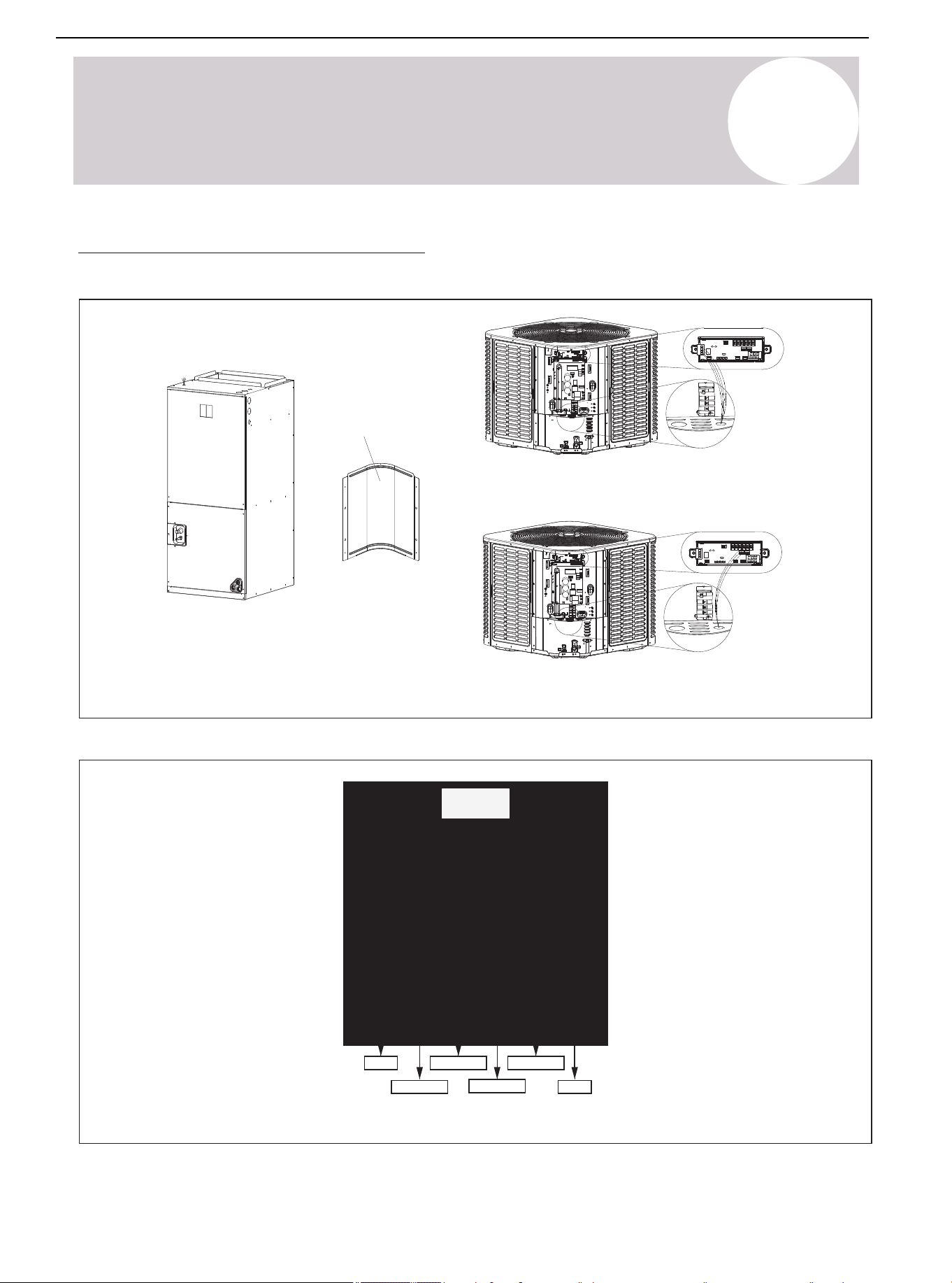
Figure 11.1. Connection of Low Voltage Device
24V Low voltage connection
RS-485 Communication low voltage connection
Control
board
access
panel
11
Electrical-Low Voltage
Low Voltage Connection Diagram
Air Conditioner Installation & User Manual
32
01 02 03 04 05 06 07 08
09 10 11 12 13 14 15 16 17 18
19 20 21 22 23 24 25
27 28
29 30 31 32 33 34 35 36 37 38
39 40 41 42 43 44 45 46 47 48
49
11
Electrical-Low Voltage
Wiring Diagram of Thermostat
• Ensure that the power supply is consistent with the nameplate of the unit.
• The power connection and grounding of the unit must comply with local regulations.
• Low voltage wiring to be No. 22 AWG minimum conductor.
• "-----" On-site installation of electrical auxiliary heat connection.
• Single-stage electric auxiliary heating supported by 2H thermostat.
• Two-stage electric auxiliary heating supported by 3H thermostat.
• W1: The first stage of electric auxiliary heating installed in the indoor unit.
• W2: The second stage of electric auxiliary heating installed in the indoor unit.
• The W signal of the outdoor unit is connected to the electric auxiliary heating or first-stage electric auxiliary
heat.
The dotted line in the following thermostat wiring diagram indicates optional wiring (wiring for passive
dehumidification and electric heating). For the wiring of the thermostat, refer to the user manual of the
thermostat.
The reversing valve is energized in Heating mode and de-energized in Cooling mode. As factory
default, the O/B terminal and reversing valve are set to be energized at the same time. Use dip
switch SW2-4 to achieve the opposite.
Air Conditioner Installation & User Manual
33
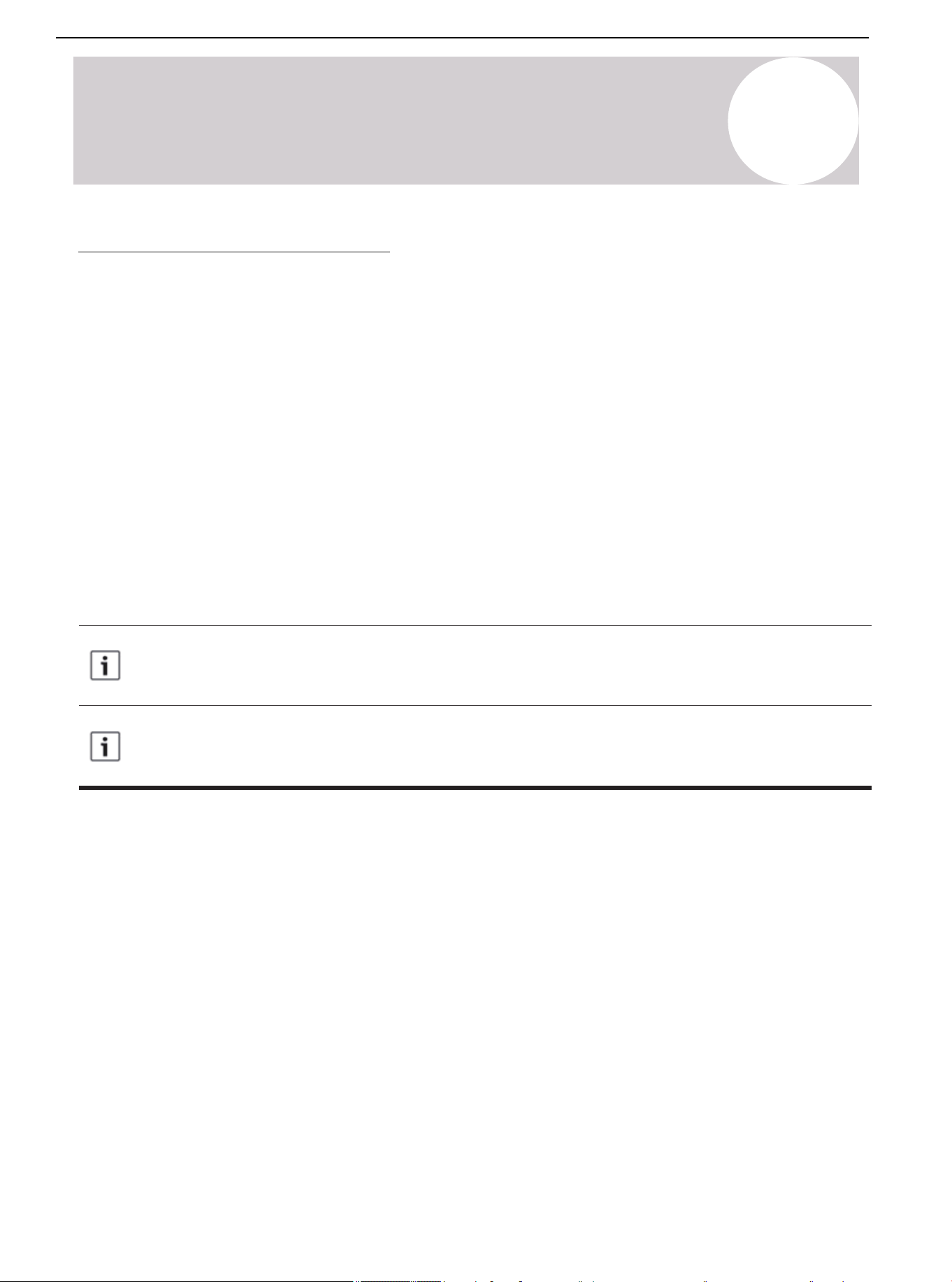
11
Electrical-Low Voltage
Water Float
Switch
Wiring for 3H and 2C thermostat
Thermostat
Note: Any time the electric heat
elements are active, the indoor
fan will run in high stage.
Indoor Unit Outdoor Unit
Y1
W/E
Y
R
G
C
O/B
H/DH
DH
B
C
GR
Y2
W1
W2
C
Y B
W
Gray
Blue
Brown
Green
Red
Yellow
Purple
White
White/Black
Brown
Yellow
Blue
White
Y2
Figure 11.3. Control Wiring for Heat Pump Systems
Water Float
Switch
Wiring for 4H and 2C thermostat
Thermostat
Note: Any time the electric heat
elements are active, the indoor
fan will run in high stage.
Indoor Unit
Outdoor Unit
W/E
Y
R
G
C
H/DH
DH
B
C G
R
Y1
Y2
W1
W2
C
Y
B W
Gray
Blue
Brown
Green
Red
Yellow
Purple
White
White/Black
Brown
Yellow
Blue
White
W2
Y2
O/B
Figure 11.4. Control Wiring for Heat Pump Systems
Air Conditioner Installation & User Manual
34
01 02 03 04 05 06 07 08
09 10 11 12 13 14 15 16 17 18
19 20 21 22 23 24 25 26
28
29 30 31 32 33 34 35 36 37 38
39 40 41 42 43 44 45 46 47 48
49
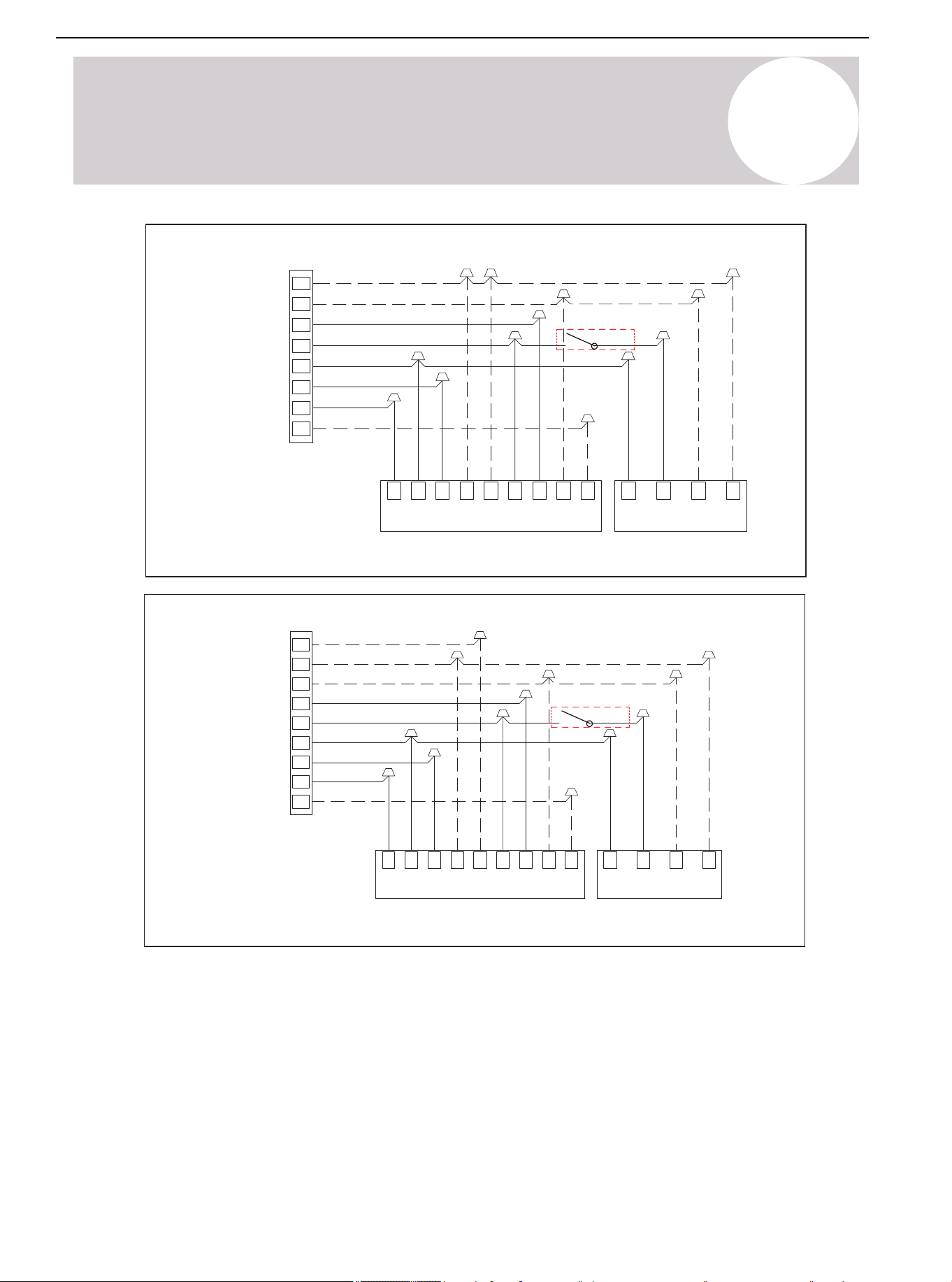
Note: Because Y1 and Y2 are
jumped, the indoor fan will only run in
high stage.
Note: Any time the electric heat
elements are active, the indoor fan
will run in high stage.
Wiring for 3H and 1C thermostat
Outdoor Unit
Indoor Unit
W/E
Y
R
G
C
O/B
H/DH
DH
B
G
C
WBYC
Y1
Y2W1
W2
R
Gray
Blue
Brown
Green
Red
Yellow
Purple
White
White/Black
Brown
Yellow
Blue
White
W2
Water Float
Switch
Figure 11.5. Control Wiring for Heat Pump Systems
Water Float
Switch
Wiring for 2H and 2C thermostat
Thermostat
Note: Any time the electric heat
elements are active, the indoor
fan will run in high stage.
Indoor Unit Outdoor Unit
Y2
Y
R
G
C
O/B
H/DH
DHB
C GR
Y1 Y2
W1 W2
C
Y
B W
Gray
Blue
Brown
Green
Red
Yellow
Purple
Brown
Yellow
Blue
Figure 11.6. Control Wiring for Heat Pump Systems
11
Electrical-Low Voltage
Air Conditioner Installation & User Manual
35
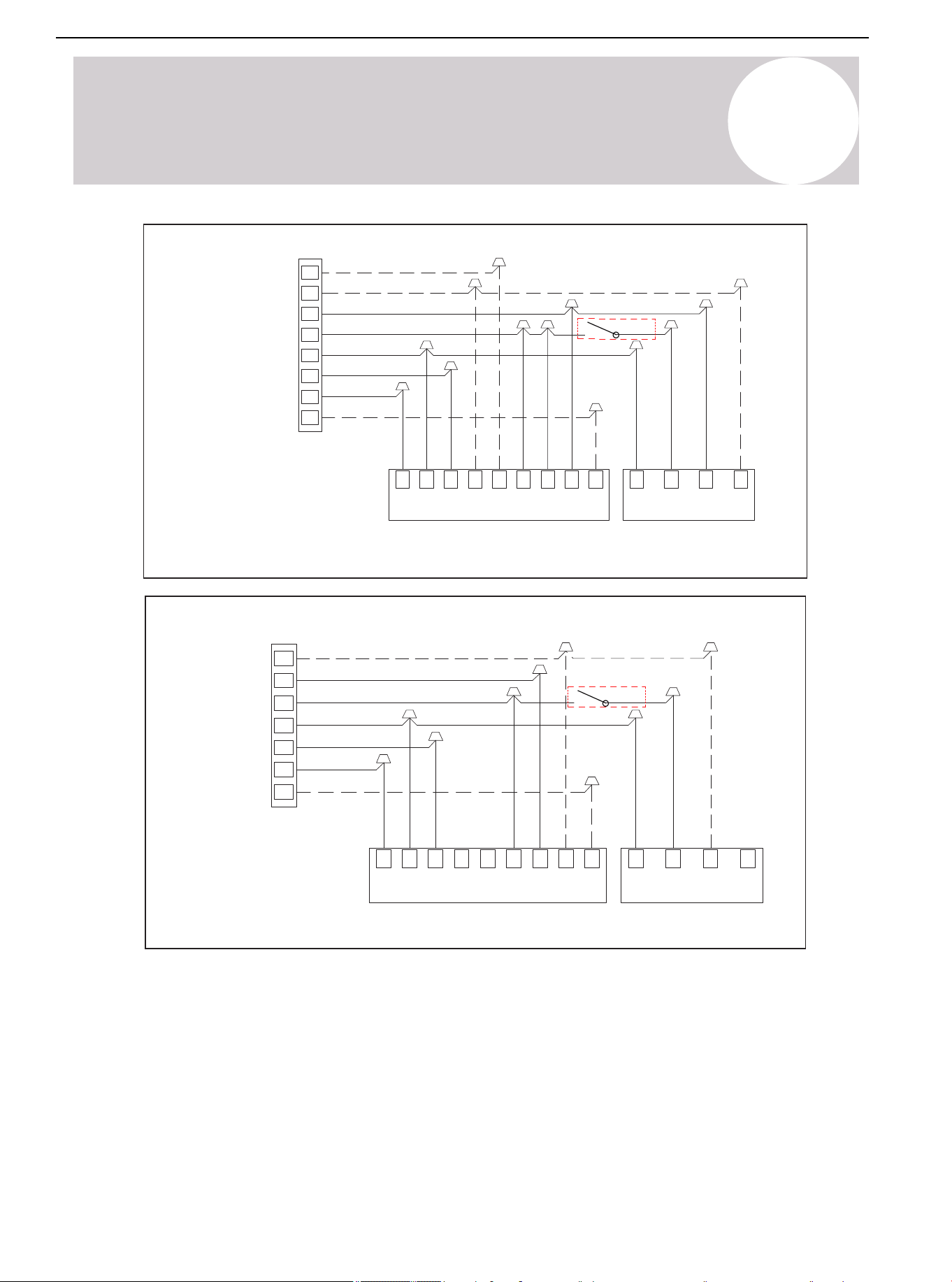
11
Electrical-Low Voltage
Water Float
Switch
Wiring for 1H and 1C thermostat
Indoor Unit Outdoor Unit
Note: Because Y1 and Y2
are jumped, the indoor fan
will only run in high stage.
Y
R
G
C
O/B
H/DH
DHB
C
GR Y1
Y2
W1 W2
C Y
B W
Gray
Blue
Brown
Green
Red
Yellow
Purple
Brown
Yellow
Blue
Figure 11.7. Control Wiring for Heat Pump Systems
Water Float
Switch
Wiring for 2H and 1C thermostat
Indoor Unit
Outdoor Unit
Note: Because Y1 and Y2 are jumped,
the indoor fan will only run in high stage.
Note: W1 and W2 are jumped, so
Electric Heat will only function in high
stage.
W/E
Y
R
G
C
O/B
H/DH
DH
B
C
G
R
Y1
Y2
W1
W2
C Y B W
Gray
Blue
Brown
Green
Red
Yellow
Purple
White
White/Black
Brown
Yellow
Blue
White
Figure 11.8. Control Wiring for Heat Pump Systems
Thermostat
Thermostat
Air Conditioner Installation & User Manual
36
01 02 03 04 05 06 07 08
09 10 11 12 13 14 15 16 17 18
19 20 21 22 23 24 25 26 27
29 30 31 32 33 34 35 36 37 38
39 40 41 42 43 44 45 46 47 48
49
12
Electrical-High Voltage
High Voltage Power Supply
Warning: Live Electrical Parts
During the installation, testing, maintenance, and troubleshooting of this product, it may be necessary
to use live electrical parts. Failure to observe all electrical safety precautions when exposed to live
electrical parts may result in death or serious injury.
The high-voltage power supply must match the nameplate of the unit (208/230V, 1 ph, 60Hz).
Power supply wiring must comply with national, state, and local regulations.
Follow the instructions of the unit wiring diagram located at the back side of the control box access panel. Refer
to the wiring diagram in this installation manual.
High Voltage Disconnect Switch
Install a separate disconnect switch on the outdoor unit.
High-voltage wiring must use a flexible electrical conduit supplied on site.
Figure 12.1.
Air Conditioner Installation & User Manual
37
01 02 03 04 05 06 07 08
09 10 11 12 13 14 15 16 17 18
19 20 21 22 23 24 25 26 27 28
30 31 32 33 34 35 36 37 38
39 40 41 42 43 44 45 46 47 48
49
Wire
Gauge
Type (Btu/ hour)
24K 36K 48K 60K
Single
Power
Stage
208/230VAC, 60 HzVoltage/Frequency
Indoor Unit
Power Cord
Outdoor Unit
Power Cord
Conductor Quantity 3
3 33
Wire Diameter (AWG)
16 16 16 16
Conductor Quantity 3 3 33
Wire Diameter (AWG)
14 12 10 10
Table 12.1. Wire Gauge of High Voltage Systems
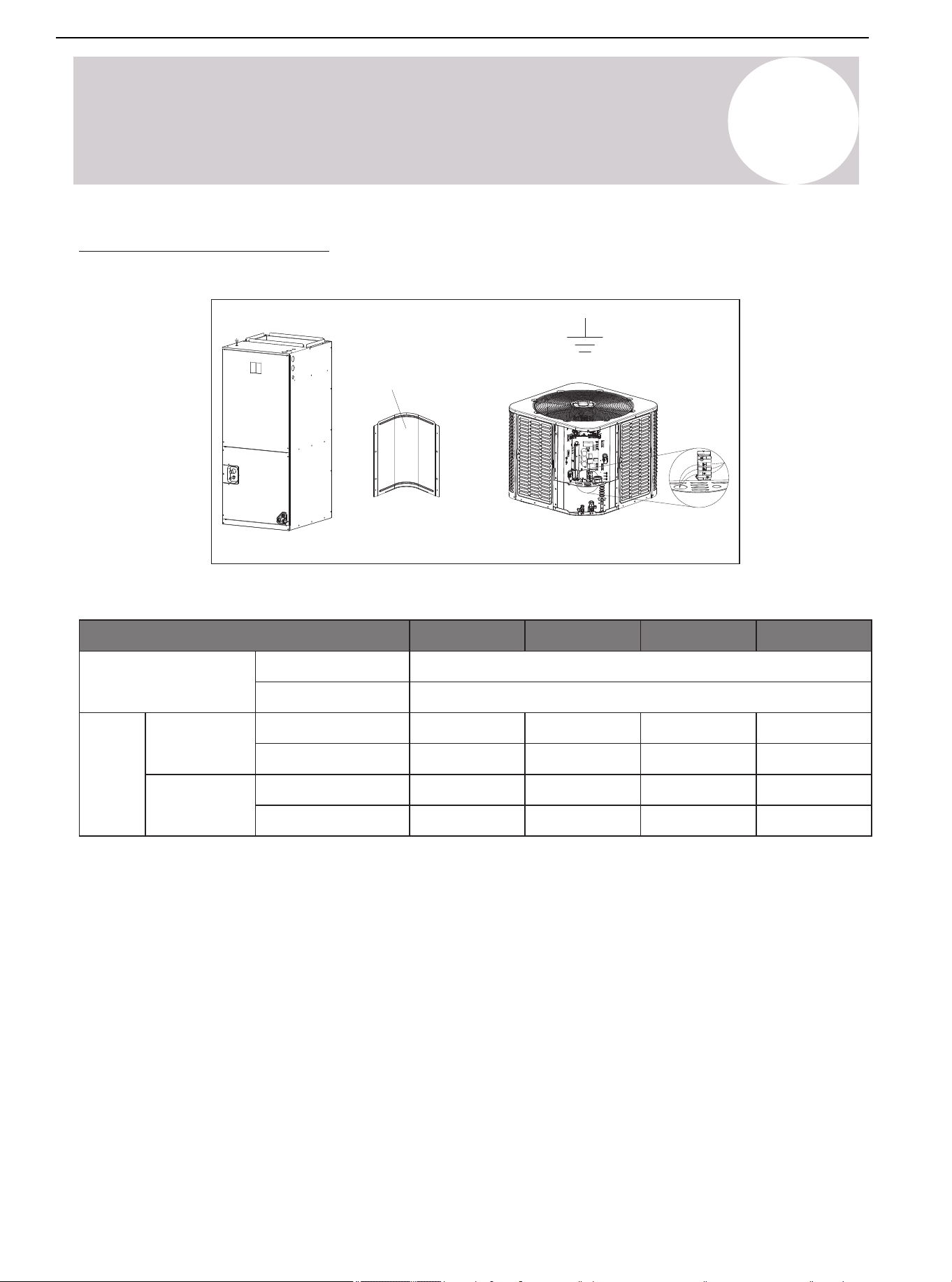
High Voltage Grounding
Ground the outdoor unit according to the requirements of national, state, and local regulations.
Figure 12.2.
Control
board
access
panel
12
Electrical-High Voltage
Air Conditioner Installation & User Manual
38
13
Start
System Startup
1. Turn off the system thermostat.
Figure 13.1.
3. Turn on the disconnect switch and apply power to the indoor and outdoor units.
Figure 13.2.
4. When starting the unit for the first time and the outdoor temperature is below 70°F (21°C), it is
recommended to power on and let the crankshaft heater preheat for 1 hour before turning on the unit. When
starting the unit for the first time in Heating mode while the outdoor temperature is below 23°F (-5°C), the
system will force to preheat for 1 hour before turning on the unit. PRH will display in the screen.
Figure 13.3.
5. Turn on the system thermostat.
Figure 13.4.
Air Conditioner Installation & User Manual
39
14
System Refrigerant Charging Method
Refrigerant Charging: Weigh-In Method
Use the weigh-in method during the initial installation or when replacing a system charge. In addition, use the
weigh-in method when power is not available to the equipment site or operating conditions (indoor/outdoor
temperatures) are not in range to verify with the subcooling charging method.
The factory charge in the outdoor unit is sufficient for 25 feet (7.62 m) of standard size interconnecting
liquid line. An additional 0.54 oz/ft of R-454B refrigerant is needed when the length of the lineset is more
than 25 feet (7.62 m).
New Installation - Calculating additional charge for lineset greater than 25 feet (7.62 m).
1. Total length of line (m/ft) = _________ (a)
2. Standard line setup = 7.62 m (25 ft) (b)
3. (a) minus (b) = _________ (c)
4. Refrigerant multiplier = 50g/m (0.54 oz/ft) (d)
5. Additional refrigerant quantity (c*d) = _________ (e)*
* If the lineset is less than 7.62 m (25 ft), e = 0
Sealed-System Repairs - Calculating total system charge
1. Total length of line (ft) = _________ (a)
2. Standard line setup (ft) = 7.62 m (25 ft) (b)
3. (a) minus (b) = _________ (c)
4. Refrigerant multiplier = 50g/m (0.54 oz/ft) (d)
5. Additional refrigerant quantity (c*d) = _________ (e)*
6. Factory filling quantity (nameplate) = _________ (f)
7. Total system charge (e + f) = _________
* If the lineset is less than 7.62 m (25 ft), e = 0
The only mode approved for verifying system charging is in Forced Cooling mode. The outdoor
temperature must be between 68-113°F (20-45°C). The indoor temperature must be between 68-89°F
(20-32°C).
You can refer to the above formula for calculation or choose the appropriate refrigerant addition according to
the piping length in the below examples.
Piping Length (ft/m)
25 / 7.6
50 / 15.2
75 / 22.9
100 / 30.5
Additional Charge (kg/oz)
0.0/0.0
0.4/13.5
0.8/27.0
1.1/40.5
Table 14.1. Additional Refrigerant Guidelines
Air Conditioner Installation & User Manual
40
14
System Refrigerant Charging Method
①
①
+②=
②
· =
· =
kg
(oz)
kg
(oz)
kg
(oz)
① Refrigerant charge of the precharged part of the appliance.
② Refrigerant charge added during installation.
Subcooling Charging & Refrigerant Adjustment in Cooling Mode
1. Check the outdoor ambient temperature.
Subcooling (Cooling mode) is the only recommended charging method when the outdoor ambient temperature is
higher than 68°F (20°C).
For outdoor ambient temperature below 68°F (20°C), use the weigh-in charging method outlined earlier.
When the outdoor ambient temperature is higher than 68°F (20°C), be sure to return in spring or
summer in order to accurately charge the system in Cooling mode.
Begin by checking the ambient temperature. Only use subcooling method (in Cooling mode) when the outdoor
temperature is between 68-113°F (20-45°C) and the indoor temperature is between 68-89°F (20-32°C). If
either temperature is out of the range, use the weigh-in method.
Air Conditioner Installation & User Manual
41

Start Forced Cooling mode. Start the system in Cooling mode, then press and hold the "SET" button until the
symbol "dC" is displayed. After entering the Forced Cooling mode, the symbol "dC" and the current compressor
frequency will show alternatively on the digital display. The Forced Cooling mode will automatically stop after 60
minutes or press and hold the "SET" button again to exit the mode manually.
14
System Refrigerant Charging Method
Press and hold the "SET" button until “dC” displays to start/quit Forced Cooling mode
Figure 14.1.
After Forced Cooling mode has started, wait 20 minutes for the system to stabilize. The compressor will maintain
a specific frequency in Forced Cooling mode.
Begin by determining the optimum subcooling value, which is based on the measured liquid line temperature
and pressure according to Table 14.2.
If the calculated subcooling value is lower than the recommended design subcooling value in Table 14.3., add
refrigerant. If the calculated subcooling value is higher than the value shown in Table 14.3., recover refrigerant.
Wait 5 minutes for the system to stabilize and repeat the steps above until the subcooling value matches the
design subcooling value shown in Table 14.3. After, remove the service tools, as well as press and hold the
"SET" button to exit Forced Cooling mode. The symbol "dC" will disappear when exiting the Forced Cooling
mode.
Air Conditioner Installation & User Manual
42
01 02 03 04 05 06 07 08
09 10 11 12 13 14 15 16 17 18
19 20 21 22 23 24 25 26 27 28
29 30 31 32
34 35 36 37 38
39 40 41 42 43 44 45 46 47 48
49
Liquid Line Temp
(°F/°C)
Subcooling Value (°F/°C)
6 7 8 9 10 11 12 13
Liquid Gauge Pressure (PSI)
55/13
60/15.5
65/18
70/21
75/24
80/27
85/29
90/32
95/35
100/38
105/40.5
110/43
115/46
120/49
125/52
164
178
194
210
227
245
264
284
305
327
351
375
401
428
456
167
181
197
213
230
249
268
288
309
332
355
380
406
433
462
170
184
200
217
234
252
272
292
314
336
360
385
412
439
468
172
187
203
220
238
256
276
297
318
341
365
390
417
445
474
175
191
206
223
241
260
280
301
323
346
370
396
422
450
480
178
194
210
227
245
264
284
305
327
351
375
401
428
456
486
181
197
213
230
249
268
288
309
332
355
380
406
433
462
492
184
200
217
234
252
272
292
314
336
360
385
412
439
468
498
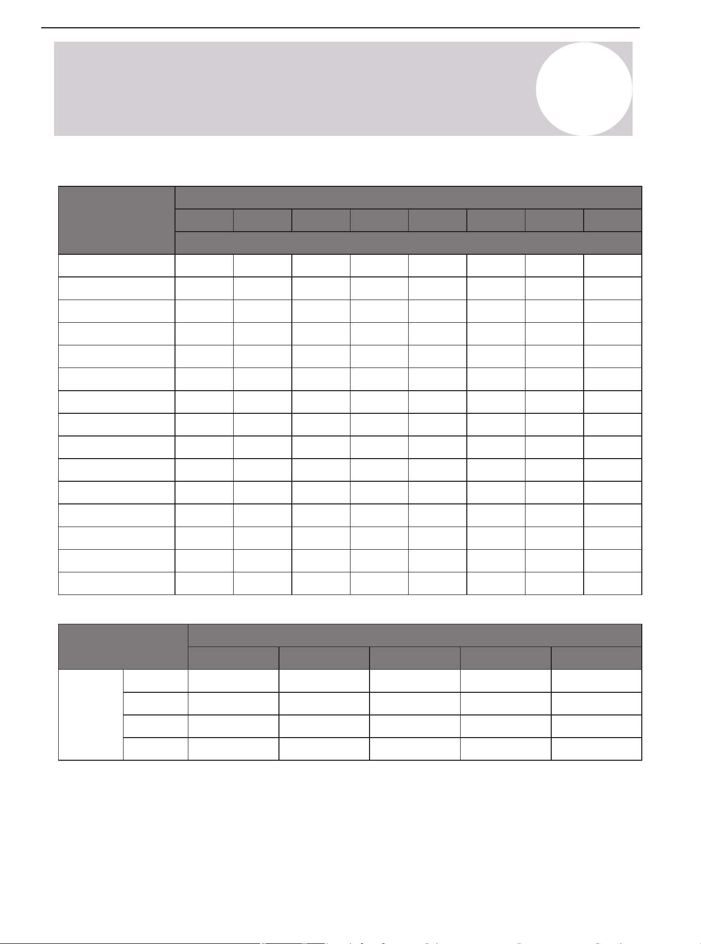
Table 14.3.
Subcooling (°F/°C)
68~77/20~25
10±2
10±2
8±2
8±2
77~86/25~30
8±2
8±2
8±2
8±2
86~95/30~35
8±2
8±2
8±2
8±2
95~104/35~40
6±2
6±2
6±2
6±2
104~113/40~45
6±2
6±2
6±2
6±2
24K
36K
48K
60K
Model
Ambient Temperature (°F/°C)
14
System Refrigerant Charging Method
Table 14.2.
Air Conditioner Installation & User Manual
43

15
System Operation & Troubleshooting
Control Logic Description
• The inverter system adopts the same 24VAC control as any conventional heat pump.
• The compressor's speed is controlled based on coil pressures monitored by the unit's pressure transducer. In
order to ensure stable and adequate capacity, the compressor speed modulates relative to the evaporator
pressure during cooling operation and the condensing pressure during heating operation.
Sensors & Valves
T3: Outdoor Coil Temperature
— High temperature protection.
— Outdoor fan control (Cooling mode).
— Defrost control (Heating mode).
T4: ODU Ambient Temperature
— Maximum compressor frequency limitation.
— Defrosting condition (Heating mode).
— Outdoor fan control (Heating mode).
T5: Compressor Discharge Temperature
— High discharge temperature / Low superheat protection.
— Electronic Expansion Valve (EEV control).
T7: Control Board Heat Pipe Temperature
— Control board anti-condensed.
Tfin: IPM Radiator Temperature
— High IPM temperature protection.
PT: Pressure Transducer
— Detect evaporating pressure in Cooling mode and condensing pressure in Heating mode.
— Compressor frequency control.
— Electronic Expansion Valve (EEV control).
— High pressure protection (Heating mode).
— Low pressure protection (Cooling mode).
PEV: Pressure Equalizer Valve
— Balance the pressure of the system before the compressor starts up.
— Reversing valve.
— Used to switch the refrigerant flow direction between Cooling and Heating mode.
Air Conditioner Installation & User Manual
44
01 02 03 04 05 06 07 08
09 10 11 12 13 14 15 16 17 18
19 20 21 22 23 24 25 26 27 28
29 30 31 32 33
35 36 37 38
39 40 41 42 43 44 45 46 47 48
49
15
System Operation & Troubleshooting
Accelerated Cooling/Heating
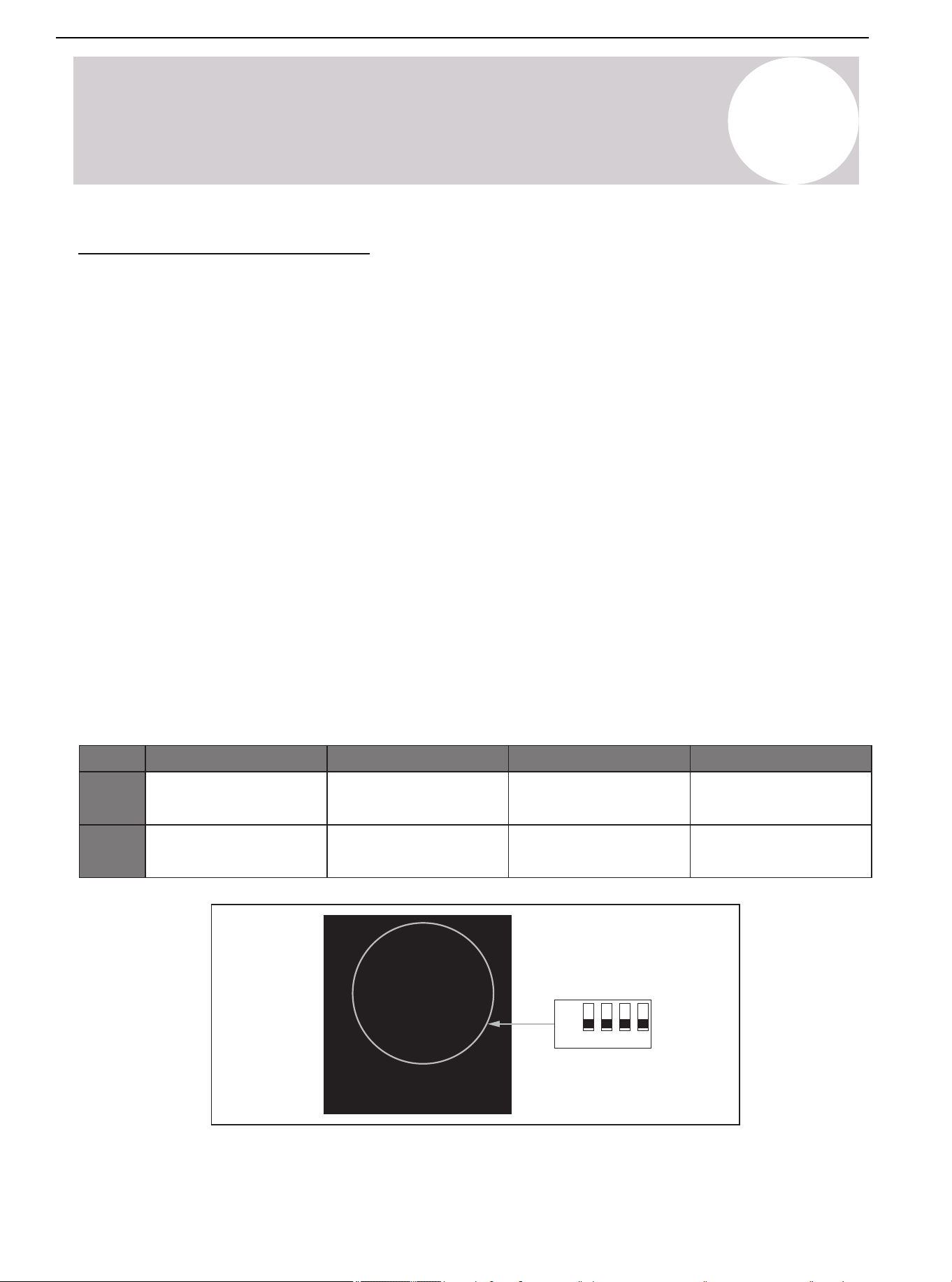
The dip switch SW3-3 and SW3-4 are set to the "Off" position by default. If switch SW3-3 is set to the "On"
position, the target coil temperature will reduce in Cooling mode. If switch SW3-4 is set to the "On" position, the
target coil temperature will increase in Heating mode. The accelerated Cooling/Heating function improves
dehumidification capacity in Cooling mode and increases unit capacity.
ON
OFF
3 4
SW3
Defrost Description
Automatic Defrost Control Function
This function monitors the outdoor coil temperature (T3 and ambient temperature) (T4 to determine whether to
defrost or not).
One of the following conditions must be met to run a defrost cycle:
1. The difference between the outdoor ambient temperature (T4) and outdoor coil temperature (T3) is called
Delta T. When T4 ≥ 19°F (-7°C) =, the compressor has run for 60 minutes or under PI control for 15 minutes.
When T3 < 30°F (-1°C) and Delta T < 46°F (8°C) lasts for 3 minutes, the unit will run a defrost cycle
automatically.
2. When the compressor has run for 120 minutes under the low ambient temperature between 14-19°F
(-10 - -7°C) and T3 < 5°F (-15°C) or the decreasing of T3 is beyond 5°F (-15°C), the unit will run a defrost cycle
automatically.
3. When T4 ≤ 14°F:
a) The compressor has run for 90 minutes and T3 ≤ -13°F (-25°C)
b) The compressor has run for 90 minutes and the decreasing of T3 is beyond 5°F (-15°C)
c) The compressor has run for 360 minutes
The unit will run a defrost cycle automatically.
Air Conditioner Installation & User Manual
45
15
System Operation & Troubleshooting
Minimum Run Time (MRT) Defrost
The MRT Defrost function is based on outdoor ambient temperature (T4). The function works if T3 is
accidentally misjudged. One of the following conditions must be met to run a defrost cycle:
a) MRT ≥ 3.5 hours and T4 < 23°F (-5°C)
b) MRT ≥ 2 hours and 23°F (-5°C) ≤ T4 < 42°F (5.5°C)
c) MRT ≥ 50 minutes and the last defrost time ≥ 7 minutes.
Low Saturated Discharge Pressure (SDP) Defrost
The function works if T3 is accidentally misjudged. When the unit has run for 20 minutes under the ambient
condition: 14°F (-10°C) ≤ T4 < 28°F (-2°C), monitor the Saturated Discharge Pressure (SDP). If the SDP drops
below 82°F (28°C), the defrost function will run.
Fixed Time Defrost
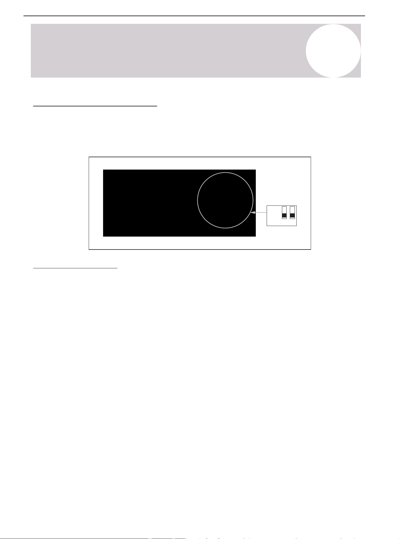
When the dip switch SW2-1 is set to the "On" position, the Fixed Time Defrost mode will activate. For different
geographical and ambient conditions, set dip switch SW2-2 to select the fix time for the defrost cycle. SW2-1
and SW2-2 are set to the "Off" position by default.
Accelerated Defrost
In this function, the Heating operation time is reduced by 10% and defrost time is extended for 60 seconds.
Valid only in the Fixed Time Defrost and Minimum Run Time Defrost functions.
Manual Defrost
Press and hold the “▼” button on the display board until the "dF" symbol appears. The "dF" symbol and
compressor frequency will display alternatively. The unit must operate in Heating mode for at least 5 minutes.
This defrost function stops automatically. After the function stops, the display board will show the compressor
speed (Hz).
O/B Signal
Check the default settings if the thermostat has O/B signal. The dip switch SW2-4 is set to the "Off" position by
factory default, which requires a B signal call from the thermostat in Heating mode. When SW2-4 is turned on,
the unit will operate in Cooling mode with an O signal from the thermostat.
ON
OFF
1 2 3 4
SW2
Defrost Description (Continued)
Air Conditioner Installation & User Manual
46
01 02 03 04 05 06 07 08
09 10 11 12 13 14 15 16 17 18
19 20 21 22 23 24 25 26 27 28
29 30 31 32 33 34 35
37 38
39 40 41 42 43 44 45 46 47 48
49
15
System Operation & Troubleshooting
Compressor Crankshaft Heater Control Function
1. Meet one of the following conditions to start the crankcase heater:
• Discharge temperature T5 < 73.4°F (23°C) and the defrost function turns on.
• Discharge temperature T5 < 73.4°F (23°C) when powered on for the first time.
• The power off duration is longer than 3 hours or more than 2 hours when powered on for the first time.
And at this time T4 < 50°F (10°C) and the discharge temperature T5 < 73.4°F (23°C).
2. Exit conditions:
Discharge temperature T5 ≥ 82.4°F (28°C)
Reversing Valve Operation
The reversing valve is energized in Heating mode and de-energized in Cooling mode.
During the heating signal of the first operation, the unit will operate in the cooling state for about 1
minute, accumulating pressure for reversing the reversing valve.
Defensive Function
Temperature Protection of the Outdoor Coil in Cooling Mode (T3)
1. If T3 > maximum set temperature, the system stops for protection.
2. If T3 < the set recovery temperature value, the system restarts.
Note: Consult the supplier for maximum temperature and recovery temperature.
Exhaust Temperature Protection (T5)
1. In Cooling or Heating mode, if the temperature is higher than the set maximum value, the system will stop for
protection.
2. In Cooling or Heating mode, if the temperature is lower than the set recovery temperature, the system will
restart.
Note: Consult the supplier for maximum temperature and recovery temperature.
IPM Module (Inverter) Protection (TF)
1. TF ≥ the highest judgment value C. If the outdoor fan does not reach the highest level at this time, the fan
speed will increase one by one. At this time, the compressor frequency is not limited. If the outdoor fan is the
highest fan speed, the current frequency is the highest allowable operating frequency.
2. TF ≥ the highest judgment value B, the compressor reduces the frequency successively.
3. TF ≥ the highest judgment value A, the compressor stands abnormally.
4. TF ≤ the highest judgment value D, the system restarts.
Note: The highest judgment value A/B/C/D are all parameters set in the program. Consult the supplier for
specific values.
Air Conditioner Installation & User Manual
47
01 02 03 04 05 06 07 08
09 10 11 12 13 14 15 16 17 18
19 20 21 22 23 24 25 26 27 28
29 30 31 32 33 34 35 36
38
39 40 41 42 43 44 45 46 47 48
49
FB
FC
FD
FE
FF
P1
P2
P3
F0
F4
F5
F6
F7
F8
F9
FA
Table 15.1.
Code Failure and Protection
E1
E2
E3
E4
E6
E7
E8
E9
Communication error (Indoor Unit)
T1 sensor error
T2 sensor error
R-454b sensor error
Refrigerant leakage error
EEPROM failure (Indoor Unit)
Fan motor error (Indoor Unit)
Communication fault of wire control
Communication failure (Outdoor Unit)
T4 outdoor ambient temperature sensor error
T5 exhaust temperature sensor error
T3 condensing temperature sensor error
T7 temperature sensor error
T7 temperature sensor error in detecting condensate risks
AC overvoltage/undervoltage protection
EEPROM failure (Outdoor Unit)
EEPROM failure of driver chip
IPM modular sensor error
HLP pressure sensor failure
T3 or T5 sensor disconnect error
HPS condenser sensor disconnected
High pressure switch error
Low pressure protection
Inverter overcurrent protection
15
System Operation & Troubleshooting
Air Conditioner Installation & User Manual
48
15
System Operation & Troubleshooting
LD
LE
LF
d0
df
dC
ATL
PRH
H7
H8
HC
HE
L0
L1
LA
LB
LC
P4
P5
P6
P7
P8
P9
PC
PD
H0
H1
H2
H3
H4
H5
H6
T5 exhaust temperature sensor high temperature protection
T3 condenser sensor high temperature protection (Cooling mode)
IPM protection
T2 freeze protection
IPM high temperature protection (Tf)
DC fan motor error
Wet operation error
High pressure abnormal error (Heating mode)
Communication fault of master board and driver chip
T3 sensor high temperature error (Cooling mode) (3 times P5 error within 180mins)
High pressure switch error (3 times P1 error within 150 mins)
High pressure abnormal in Heating mode (3 times PD error within 180 mins)
IPM modular high temperature error (3 times P8 within 120 mins)
Low pressure error (5 times P2 within 240 mins)
Discharge temperature abnormal error (3 times P4 within 100 mins)
Wet operation error (3 times PC within 200 mins)
T3 condenser sensor disconnect error (3 times FE within 120 mins)
Discharge temperature sensor disconnect error (3 times FE within 180 mins)
Condensate error (3 times F8 within 60 mins)
DC cable bus low voltage protection
DC cable bus high voltage protection
Frequency limitation by voltage
Frequency limitation or decline by high pressure
Frequency limitation by condenser temperature
Frequency limitation by discharge temperature
Frequency limitation by IPM modular high temperature
Frequency limitation by current
Oil return
Defrost
Force cooling
Overtemperature protection
Crankcase heater preheating, can not start
Air Conditioner Installation & User Manual
49
01 02 03 04 05 06 07 08
09 10 11 12 13 14 15 16 17 18
19 20 21 22 23 24 25 26 27 28
29 30 31 32 33 34 35 36 37
39 40 41 42 43 44 45 46 47 48
49
2 Ton
3 Ton
4 Ton
5 Ton
Off
Off
On
On
SW3-1 SW3-2
On
Off
Off
On
Mode
Factory default
Factory default
Remark
15
System Operation & Troubleshooting
Capacity Configuration Selection
System software will recall performance setting parameters according to the DIP switch selection. The DIP
should be set according to the matched IDU.
ON
OFF
1 2
SW3
Air Conditioner Installation & User Manual
50
01 02 03 04 05 06 07 08
09 10 11 12 13 14 15 16 17 18
19 20 21 22 23 24 25 26 27 28
29 30 31 32 33 34 35 36 37 38
40 41 42 43 44 45 46 47 48
49
15
System Operation & Troubleshooting
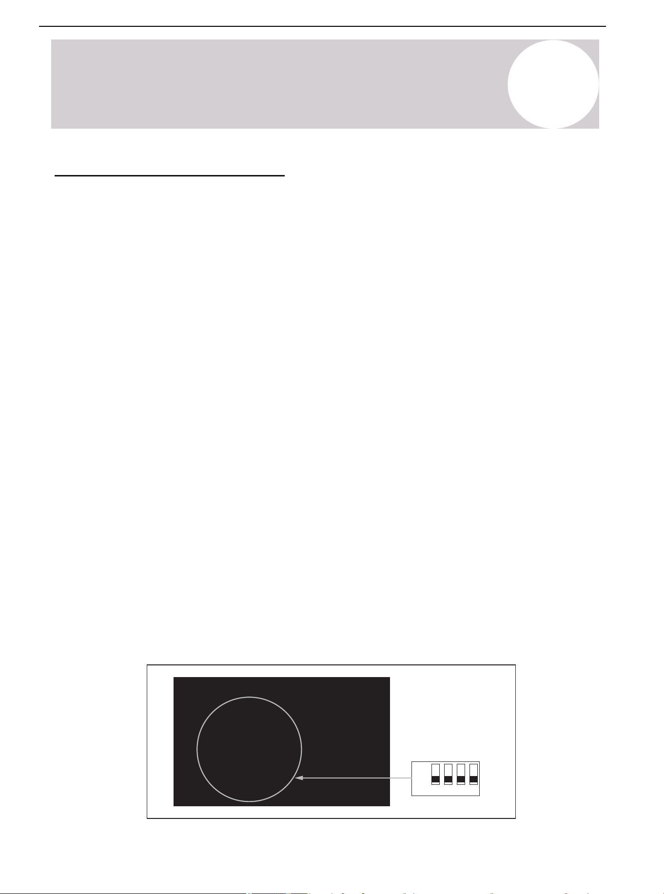
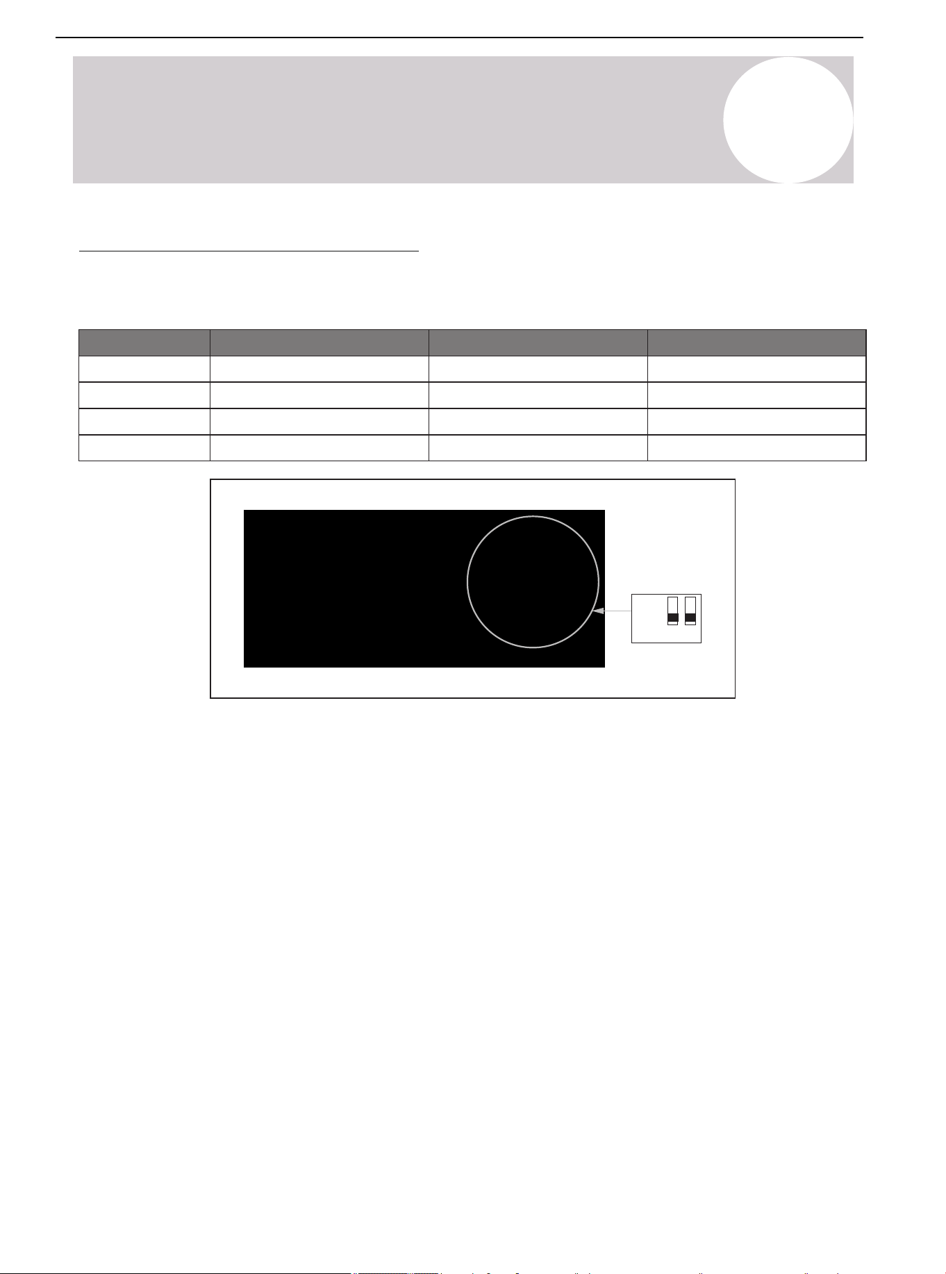
SW1 DIP Switch Description
For the 24V thermostat to control the unit, turn off dip switch SW1-1. For RS485 communication mode, turn on
dip switch SW1-1. The RS-485 communication mode is only valid for manufacturer-approved match indoor and
outdoor systems. The manufacturer supplied RS-485 communicative thermostat is optional. The benefits of the
RS-
485 communication mode:
- Modulates compressor speed for indoor temperature to achieve higher energy efficiency and comfort.
- Error codes display on the thermostat.
- Allows the end user to remotely control the system via the manufacturer's app.
The dip switch SW1-2 is for selecting the unit's display temperature and pressure.
The dip switch SW1-3 is for switching between Cool Only (AC) and Heat Pump (HP).
USB Port Software Update
Dip switch SW1-4 is for the USB Port Software Update function.
1. Turn off the power supply.
2. Turn on dip switch SW1-4.
3. Insert the USB flash drive into the USB port.
4. Turn the power supply back on.
5. The LED display will show the symbol "1".
6. After the symbol displays, turn the SW1-4 dip switch back off.
7. The LED display will show the symbols "2" and "3".
8. After the update is completed, the symbol "8.8.8" will appear on the LED display, then disappear.
ON
OFF
1 2 3 4
SW1
24V thermostat
(Factory default)
SW1-1 SW1-2
°F & PSI
(Factory default)
HP
(Factory default)
SW1-3 SW1-4
Off
RS-485
°C & MPa
AC
USB Port
Software Update
On
Software Update
(Factory default)
Air Conditioner Installation & User Manual
51
01 02 03 04 05 06 07 08
09 10 11 12 13 14 15 16 17 18
19 20 21 22 23 24 25 26 27 28
29 30 31 32 33 34 35 36 37 38
39
41 42 43 44 45 46 47 48
49
11
12
13
14
15
16
17
18
19
32
33
34
35
36
37
38
39
Table 15.2.
No.
00
01
02
03
04
05
06
07
08
09
10
Display content
Unit type: 0 = top discharge unit; 1 = side discharge unit;
2 = rooftop unit
Outdoor power (Model)
Running mode (0: Standby mode; 2: Cooling mode; 3:
Heating mode)
Target frequency (Hz; Actual value)
Actual frequency (Hz; Actual value)
Running frequency (Hz; Actual value)
T3 condensing temperature (°F; Actual value)
T4 outdoor ambient temperature (°F; Actual value)
T5 exhaust temperature (°F; Actual value)
Temperature transform by pressure sensor (°F; Actual value)
IPM modular temp Tip
m
(°F; Actual value)
Target temp Ttrg (°F; Actual value)
Discharge temp superheat (°F; Actual value)
Target superheat (°F; Actual value)
Fan speed ( Actual value / 10)
EXV opening degree (step; Actual value)
Pressure value (PSI; Actual value)
Pressure valve transform by T3 (PSI; Actual value)
AC voltage (VAC; Actual value)
DC voltage (VDC; Actual value)
20
21
22
23
24
25
26
27
28
29
30
31
AC current (A; Actual value)
Compressor current
Oil output (CC; Actual value)
T1 indoor ambient temperature (°F; Actual value)
T2 indoor evaporator temperature (°F; Actual value)
Concentration value
Enter PI control sign (0 or 1)
Enter defrosting type
Test mode (1-40; Mode gear)
Frequency increase (Shift; Actual value)
△
EV (step; Actual value)
PFC control state
Frequency limit item
Driving failure code subdivision 1
Driving failure code subdivision 2
Last failure or protection code
Software version number (1-255)
T7 condensing temperature (°F; Actual value)
T30 temperature (°F; Actual value)
Compression ratio
Check Table
15
System Operation & Troubleshooting
Press the "CHK" (K4) button to display and run through the series of parameters available. After pressing the
"CHK" button, the unit will display the parameter number. After 1 second, the unit will display the value of the
parameter. Pressing the "CHK" button again will advance to the next parameter number. (Refer to Table 15.2.)
▲: Check button and set the parameter "+"
▼: Check button and set the parameter "-"
Air Conditioner Installation & User Manual
52
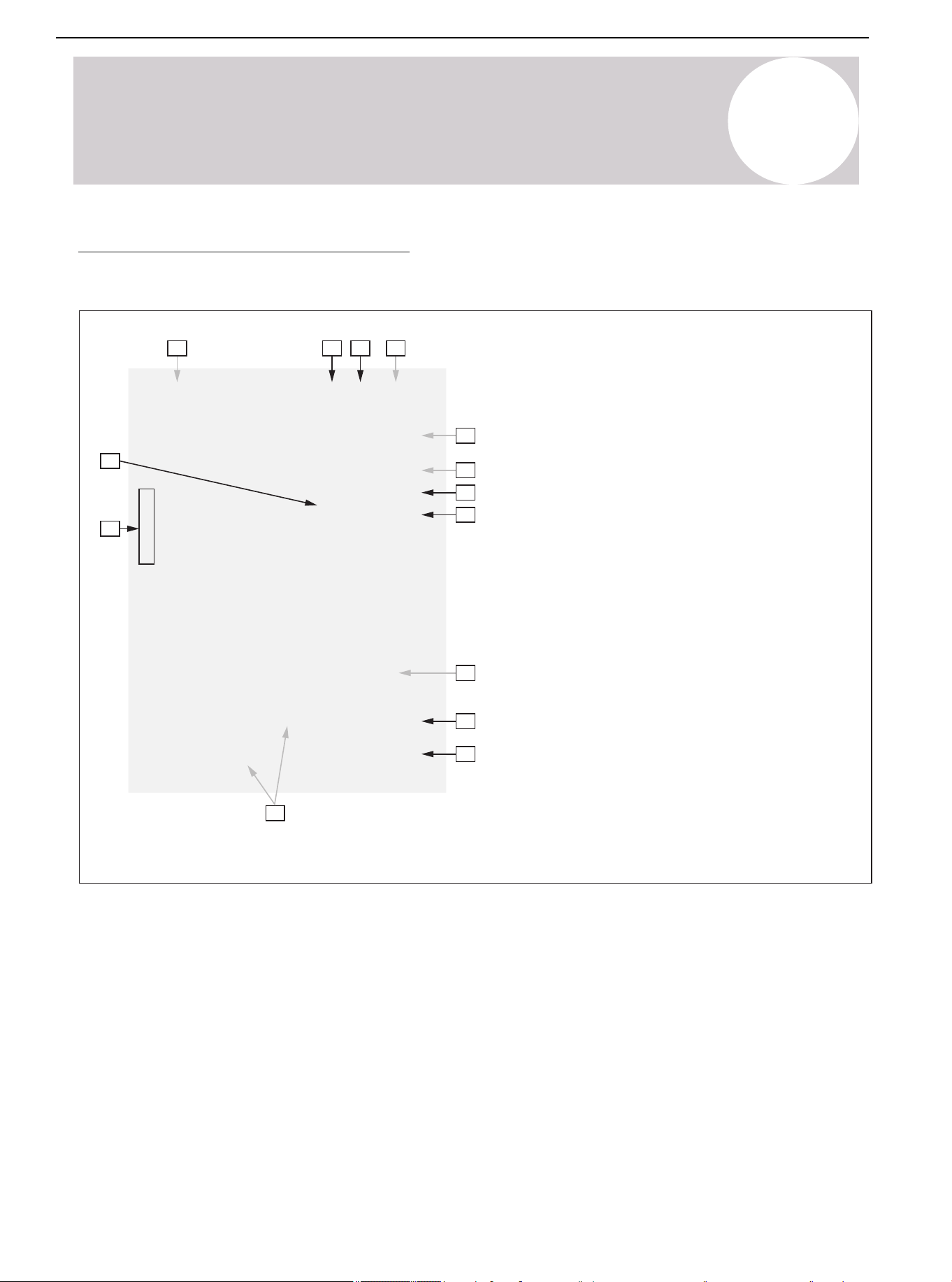
01 02 03 04 05 06 07 08
09 10 11 12 13 14 15 16 17 18
19 20 21 22 23 24 25 26 27 28
29 30 31 32 33 34 35 36 37 38
39 40
42 43 44 45 46 47 48
49
Figure 15.1. 5P Outdoor Main Control Board
Functional description
Power supply input L (L1)
Power supply input N (L2)
Ground wire
Crankshaft heating port
Four-way valve port
Solenoid valve port
Display board port
Electronic expansion valve (EEV) port
T3 T4 TP sensor port
High pressure protection switch port
Pressure sensor port
DC motor port
Compressor port U V W
Reactor port
No.
1
2
3
4
5
6
7
8
9
10
11
12
13
14
1
14
4
5
6
7
891011
12
13
2
3
15
System Operation & Troubleshooting
Overview of Main Control Board
Outdoor Main Control Board
Air Conditioner Installation & User Manual
53
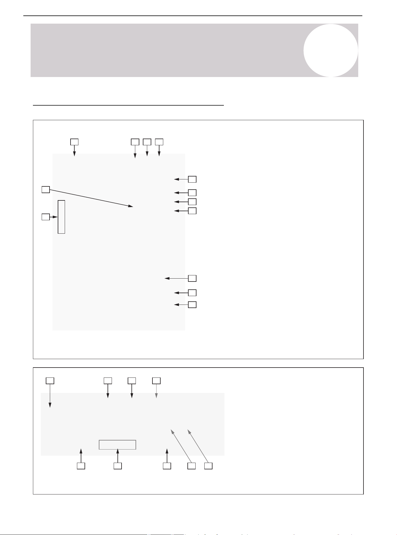
15
System Operation & Troubleshooting
Figure 15.2. 3P Outdoor Main Control Board
Figure 15.3. Display Board
Functional description
Power supply input L (L1)
Power supply input N (L2)
Ground wire
Crankshaft heating port
Four-way valve port
Solenoid Valve port
Display board port
Electronic expansion valve (EEV) port
T3 T4 TP sensor port
High pressure protection switch port
Pressure sensor port
DC motor port
Compressor port U V W
No.
1
2
3
4
5
6
7
8
9
10
11
12
13
Functional description
Display board port
Switch (K1 K2 K3 K4)
T7 sensor port
Dip switch SW1
Dip switch SW2
RS-485 communication port
Dip switch SW3
USB port
24V communication port
No.
1
2
3
4
5
6
7
8
9
891011
1
4
5
6
7
2
3
12
13
1
2 3 4 5
6789
Air Conditioner Installation & User Manual
Overview of Main Control Board (Continued)
54
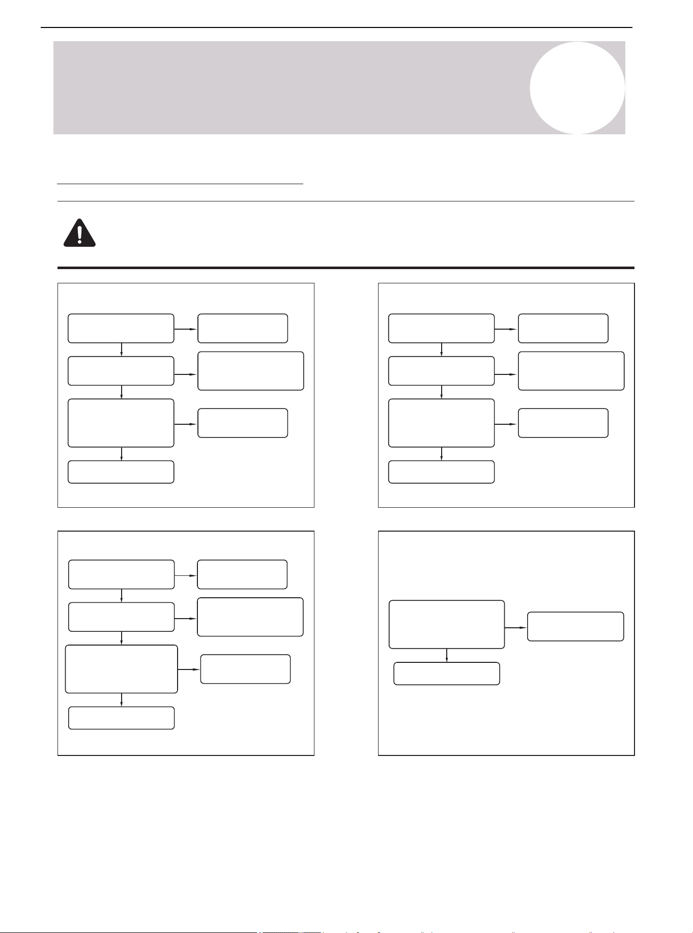
01 02 03 04 05 06 07 08
09 10 11 12 13 14 15 16 17 18
19 20 21 22 23 24 25 26 27 28
29 30 31 32 33 34 35 36 37 38
39 40 41
43 44 45 46 47 48
49
15
System Operation & Troubleshooting
Troubleshooting for Error Codes
Warning: Dangerous Voltage
When measuring the resistance, ensure that the unit's power is turned off and wait for 3 minutes
before measuring.
Figure 15.4. Figure 15.5.
F4 (T4 Outdoor Ambient Temperature Sensor Failure)
T4 sensor position is
wrong
T4 sensor wiring is
correct?
Is the resistance value of
T4 sensor within the table
range?
Correct position
Refer to
the wiring diagram for
correct wiring
No
Yes
No
Yes
Yes
No
No
Yes
No
No
F6 (T3 Condenser Temperature Sensor Failure)
T3 sensor position is
wrong
T3 sensor wiring is
correct?
Is the resistance value of
T3 sensor within the table
range?
Correct position
Refer to
the wiring diagram for
correct wiring
Figure 15.6. Figure 15.7.
F5 (T5 Exhaust Temperature Sensor Failure)
T5 sensor position is
wrong
T5 sensor wiring is
correct?
Is the resistance value of
T5 sensor within the table
range?
Correct position
Replace T5 sensor
Refer to
the wiring diagram for
correct wiring
No
Yes
Yes
No
No
FC/H4/P8 (IPM Module Sensor Failure;
High Temperature Protection)
Check the 19th numerical
value.
Is the temperature value
displaying normally?
Wait for the module to
cool down
Yes
Yes
Replace mainboard
Replace T4 sensor
Yes
Replace mainboard
Replace T3 sensor
Replace mainboard
Yes
Replace mainboard
No
Air Conditioner Installation & User Manual
55
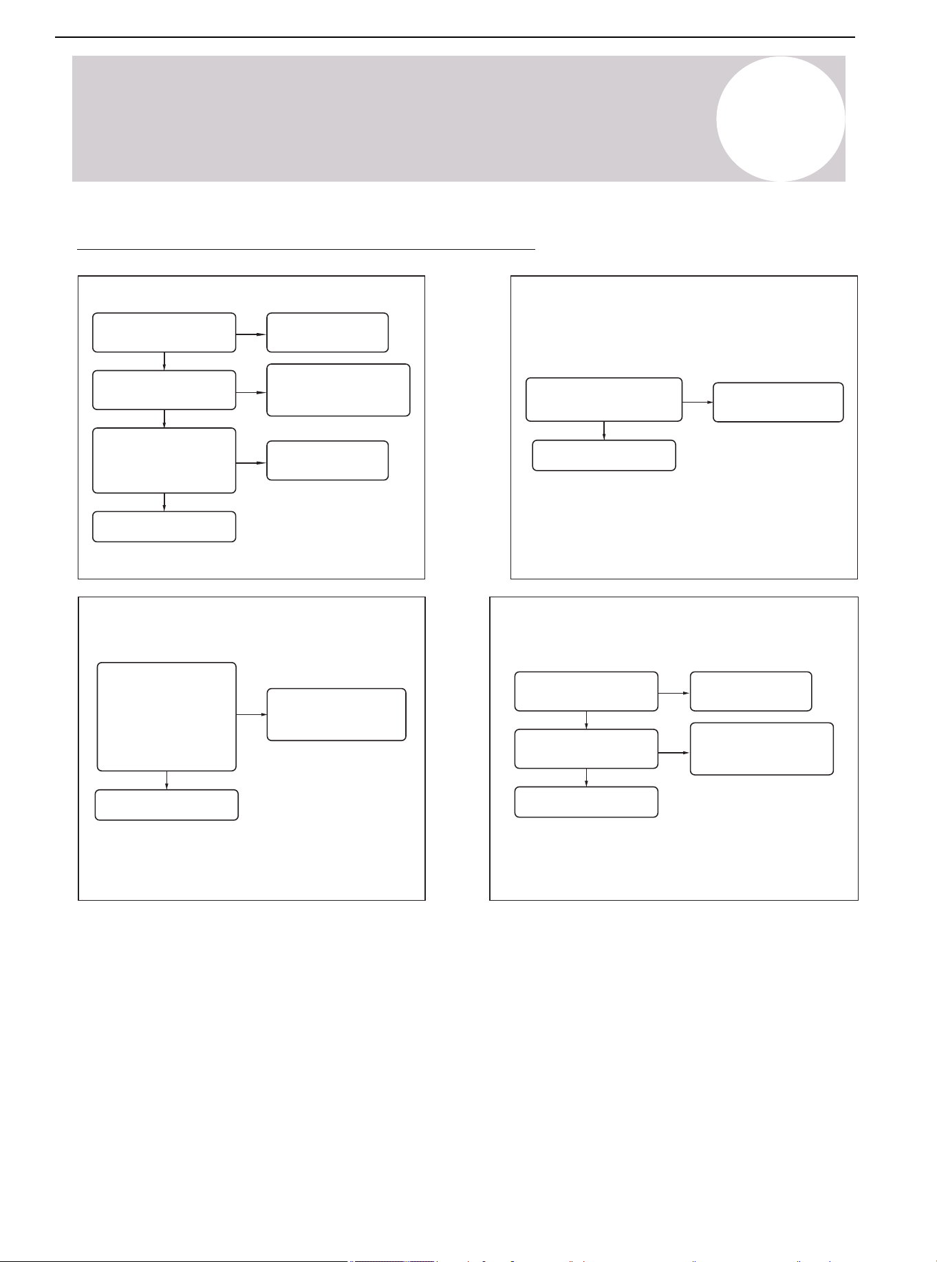
01 02 03 04 05 06 07 08
09 10 11 12 13 14 15 16 17 18
19 20 21 22 23 24 25 26 27 28
29 30 31 32 33 34 35 36 37 38
39 40 41 42
44 45 46 47 48
49
Figure 15.9.
FE (T3 / T5 Sensor is Not Tightly Plugged In & the
Unit Stands By Abnormally)
Check whether T3/T5
sensor is plugged in
Reset sensor
Yes
Figure 15.8.
FD (HLP Pressure Sensor Failure)
Sensor pressure
position is wrong
Is the pressure sensor
wiring positive?
Is the pressure sensor
resistance within
the range
(consult the supplier)
Correct position
Replace the
pressure sensor
Refer to
the wiring diagram for
correct wiring
No
Yes
Yes
No
No
15
System Operation & Troubleshooting
Figure 15.11.
FA (Outdoor EEPROM Failure)
E-chip virtual welding?
EEPROM data
is incorrect?
Weld well
Refresh the data of
EEPROM and restart
the system
No
Yes
Yes
Figure 15.10.
F9 (Undervoltage on Primary Side)
Check item 13. Is the
converted value
higher or lower than
the limit value?
(Communicate with
suppliers)
System normal
protection. Check the
power supply system
Yes
Replace mainboard
Yes
No
Replace mainboard
No
Restart the system
Replace mainboard
No
Troubleshooting for Error Codes (Continued)
Air Conditioner Installation & User Manual
56
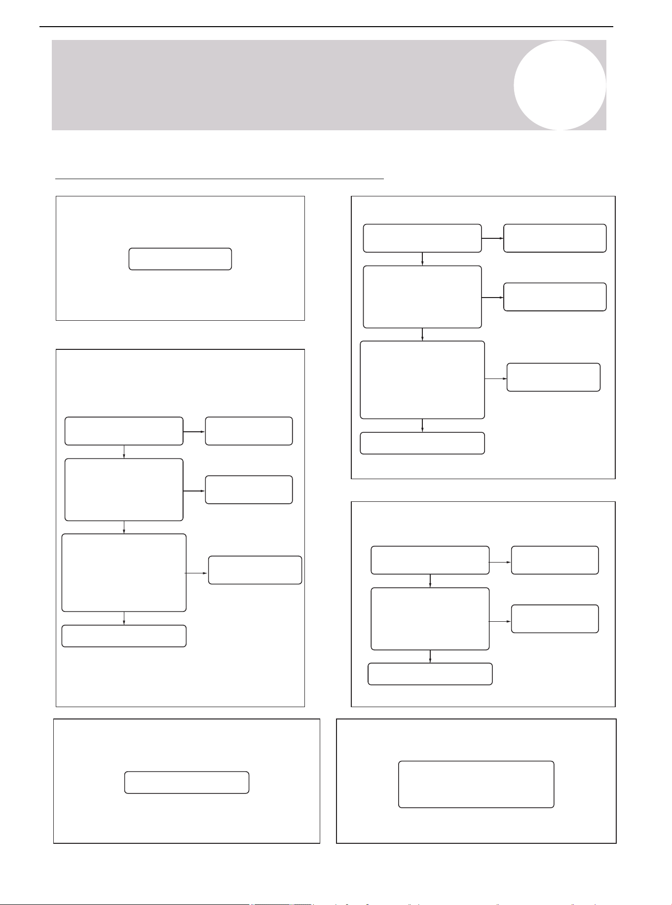
01 02 03 04 05 06 07 08
09 10 11 12 13 14 15 16 17 18
19 20 21 22 23 24 25 26 27 28
29 30 31 32 33 34 35 36 37 38
39 40 41 42 43
45 46 47 48
49
Figure 15.14.
H3/PD (High Pressure Abnormal Failure Protection
in Heating Mode)
The pressure sensor is
not connected properly
Check whether the
pressure sensor is
disconnected. Is the
measurable total
resistance infinite?
Check whether the evaporator
is dirty or blocked? Is the
surrounding environment well
ventilated? Is the outdoor fan
running normally? Is the
peripheral sheet metal
installed well?
Replace mainboard
Reconnect the
pressure sensor
Eliminate peripheral
factors one by one
Replace pressure
sensor
No
No
Yes
Yes
No
Figure 15.15.
H5/P2 (Low Pressure Abnormal Failure Protection)
Figure 15.12.
Shut-off valve is not open
Check whether the
refrigerant pressure value
in item 22 is lower than the
minimum value (consulting
suppliers)
Restart the system
Add refrigerant
No
Yes
Yes
Figure 15.13.
H2/P1 (High Pressure Switch Protection)
The high-pressure switch is
not connected properly
Check whether the
high-pressure switch is
disconnected?
Check whether the condenser
is dirty or blocked?
Is the surrounding
environment well ventilated? Is
the outdoor fan running
normally? Is the
peripheral sheet metal
installed well?
Plug in the high-pressure
switch correctly
Eliminate peripheral
factors one by one
Plug in the
high-pressure switch
No
Yes
15
System Operation & Troubleshooting
H0 (Communication Failure Between
Main Control Chip and IPM Chip)
Replace mainboard
Yes
Replace mainboard
Yes
Yes
No
No
No
Replace mainboard
Figure 15.16.
PC/H7 (Wet Operation Abnormal Protection)
System normal protection
Figure 15.17.
P6 (IPM Module Protection)
1. Check the frequency limit items
and contact the supplier.
2. Replace the mainboard.
Troubleshooting for Error Codes (Continued)
Air Conditioner Installation & User Manual
57
01 02 03 04 05 06 07 08
09 10 11 12 13 14 15 16 17 18
19 20 21 22 23 24 25 26 27 28
29 30 31 32 33 34 35 36 37 38
39 40 41 42 43 44
46 47 48
49
Figure 15.18.
H6/P4 (T5 Exhaust High Temperature Abnormal Protection)
The pressure sensor is
not connected properly
Check whether the
pressure sensor is
disconnected. Is the
measurable total
resistance infinite?
Check whether the evaporator
is dirty or blocked? Is the
surrounding environment well
ventilated? Is the outdoor fan
running normally? Is the
peripheral sheet metal
installed well?
Reconnect the
pressure sensor
Eliminate peripheral
factors one by one
Replace pressure
sensor
No
No
Yes
Yes
Check whether the refrigerant
pressure is too low?
Add refrigerant
Yes
No
No
Figure 15.21.
P9 (Outdoor DC Fan Failure)
Wrong wiring of
fan motor?
There is a foreign body
blocking the fan?
Replace the motor to see if
it can run normally?
No
No
Yes
Yes
Yes
Figure 15.19.
P3 (Overcurrent Protection of Primary Side or Secondary Side)
Figure 15.20.
L0/L1 (DC Cable Bus Low/High Voltage Protection)
Check item 14. Is the converted
value higher or lower than
the limit value?
(Communicate with suppliers)
Communicate with
suppliers on
troubleshooting
measures
Yes
Check whether the evaporator is
dirty or blocked? Is the
surrounding environment well
ventilated? Is the outdoor fan
running normally? Is the
peripheral sheet metal installed
well?
Eliminate peripheral
factors one by one
Yes
15
System Operation & Troubleshooting
Replace mainboard
Yes
Replace mainboard
No
Replace mainboard
Replace mainboard
No
Rewiring fan motor
Troubleshoot and
restart the system
Restart the system
Troubleshooting for Error Codes (Continued)
Air Conditioner Installation & User Manual
58
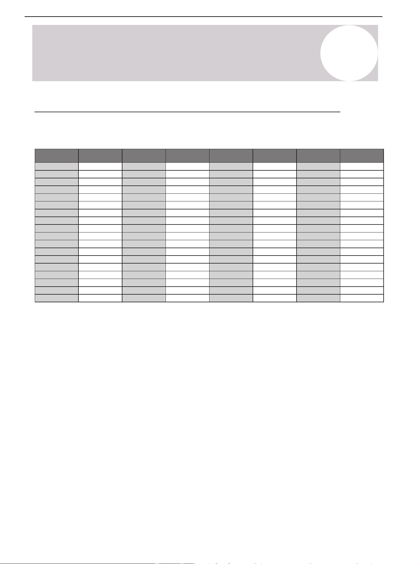
01 02 03 04 05 06 07 08
09 10 11 12 13 14 15 16 17 18
19 20 21 22 23 24 25 26 27 28
29 30 31 32 33 34 35 36 37 38
39 40 41 42 43 44 45
47 48
49
Temperature °F Temperature °C
Electric
Resistance kΩ
Volt DC
Electric
Resistance kΩ
Volt DCTemperature °F Temperature °C
-5 -20.6
33.367 0.57
0 -17.8 29.227 0.64
5 -15 25.657 0.72
10 -12.2 22.595 0.80
15 -9.4 19.942 0.89
20 -6.7 17.697 0.98
25 -3.9 15.673 1.08
30 -1.1 13.917 1.18
40 4.4 11.060 1.40
45 7.2 9.867 1.52
50 10 8.823 1.64
55 12.8 7.884 1.76
60 15.6 7.101 1.89
65 18.3 6.409 2.01
70 21.1 5.767 2.14
75 23.9 5.150 2.28
80
26.7
4.700 2.39
85 29.4 4.266 2.51
90 32.2 3.865 2.63
95 35 3.508 2.75
100 37.8 3.187 2.87
105 40.6 2.900 2.99
110 43.3 2.652 3.09
115 46.1 2.421 3.20
120 48.9 2.214 3.30
125 51.7 2.025 3.40
130 54.4 1.861 3.49
135 57.2 1.706 3.58
140 60 1.567 3.66
145 62.8 1.442 3.74
150 65.6 1.327 3.82
155 68.3 1.226 3.89
160 71.1 1.132 3.96
165 73.9 1.046 4.02
170 76.7 0.967 4.08
15
System Operation & Troubleshooting
Temperature-Resistance Relationship Table (For T3, T4, T7 Sensor)
Table 15.3. for T3, T4, T7
Air Conditioner Installation & User Manual
59
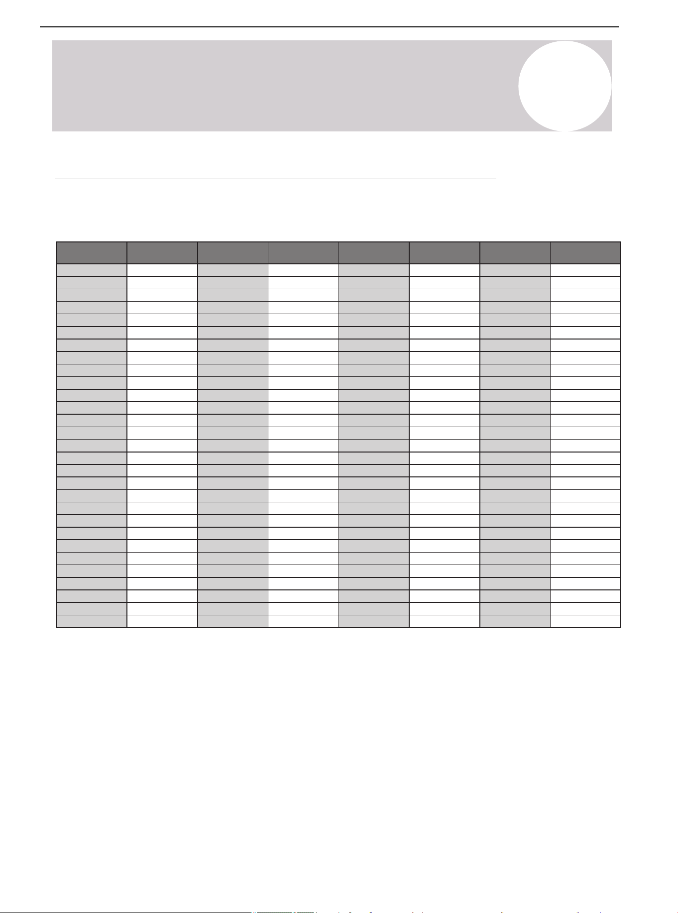
15
System Operation & Troubleshooting
Temperature °F Temperature °C
Electric
resistance kΩ
Volt DC
Electric
resistance kΩ
Volt DCTemperature °F Temperature °C
-5 -20.6
-17.8
-15
-12.2
-9.4
-6.7
-3.9
-1.1
4.4
7.2
10
12.8
15.6
0
5
10
15
20
25
30
1.735
40
45
50
55
60
496.38 0.08
0.09
0.11
0.13
0.15
0.17
0.19
0.22
0.29
0.33
0.37
0.42
0.48
422.97
361.35
309.74
266.152
230.462
198.968
172.231
0.26149.467
130.642
113.87
99.456
87.095
76.425
60140 1.9712.348
62.8145 2.1011.164
65.6150 2.2210.106
68.3155 2.349.193
71.1160 2.468.344
73.9165 2.587.585
76.7
170
2.69
6.904
79.4175 2.806.313
82.2180 2.925.761
85185 3.025.263
87.8190 3.134.815
90.6195 3.234.410
93.3200 3.334.057
96.1205 3.423.724
65 18.3
21.1
23.9
26.7
29.4
32.2
35
37.8
43.3
46.1
48.9
51.7
54.4
70
75
80
85
90
95
100
40.6105
110
115
120
125
130
67.501 0.53
0.60
0.67
0.74
0.82
0.90
0.99
1.09
1.29
1.39
1.51
1.62
1.73
59.457
52.489
46.429
41.322
36.682
32.619
29.068
1.1925.948
23.291
20.855
18.708
16.809
15.184
57.2135 1.8513.682
98.9210 3.513.423
101.7215 3.603.149
104.4220 3.672.910
107.2225 3.752.689
110230 3.822.476
112.8235 3.892.288
115.6
240
3.96
2.117
118.3245 4.021.965
121.1250 4.081.821
123.9255 4.131.690
126.7260 4.191.569
129.4265 4.231.462
132.2270 4.281.360
135275 4.321.266
137.8280 4.361.180
Temperature-Resistance Relationship Table (For T5 Sensor)
Table 15.4. for T5
Air Conditioner Installation & User Manual
60
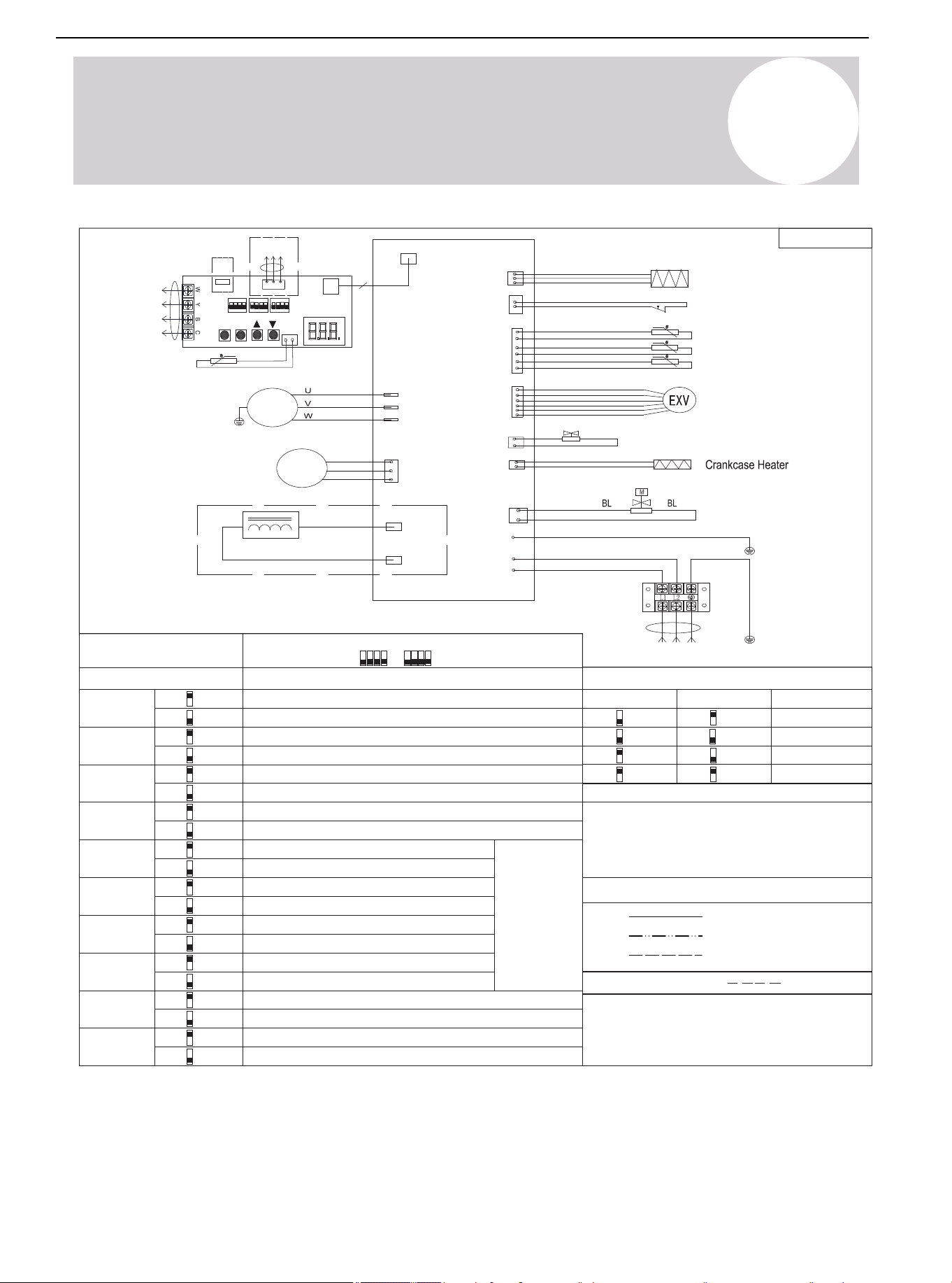
01 02 03 04 05 06 07 08
09 10 11 12 13 14 15 16 17 18
19 20 21 22 23 24 25 26 27 28
29 30 31 32 33 34 35 36 37 38
39 40 41 42 43 44 45 46
48
49
Wire Color Code
Factory Settings
SW3-1 SW3-2 Mode
24K (2T)
Factory Settings
Model
SW1-1
Check
RS-485 communication mode
RD (RED) OR (ORANGE) BK (BLACK)
BR (BROWN) BL (BLUE) GN (GREEN)
PR (PURPLE) WH (WHITE) GY (GREY)
YE (YELLOW)
The wiring diagram is for explanation purpose
only and the actual shape of the components
may be different.
Wire Information
Note 1:
24V control (factory default)
SW1-3
USB upgrade
Reserved (factory default)
SW1-4
System operation mode: Cooling only
System operation mode: Heat pump (factory default)
SW3-3
Accelerated cooling
Normal cooling (factory default)
SW3-4
Accelerated heating
Normal heating (factory default)
36K (3T)
48K (4T)
60K (5T)
SW2-1
Fix timed defrost
Defrosting
control
mode
Auto defrost (factory default)
SW2-2
Timer 30 min
Timer 60 min (factory default)
SW2-3
Powerful defrosting
Normal (factory default)
SW2-4
Thermostat O/B signal is opposite
Normal (factory default)
SW1-2
Display unit: ℃ & Mpa
Display unit: ℉ & PSI (factory default)
On
Off
Off
Off
Off
Off
On
On
On
On
On
Off
On
Off
On
Off
On
Off
On
Off
On
Off
On
Off
On
Off
On
Off
On
On
(Factory default)
802035000124
Exhaust temp
Outdoor coil temp
HP
CN106
(T3)
(TP/T5)
(T4)
Pressure Sensors
CN10
Power Supply
Outdoor ambient temp
RD
RD
CN7
(DC-FAN)
DC
Motor
W
V
U
YE/GN
YE/GN
GND
Outdoor Display Board
4
CN2(L)
CN1(N)
GND
Comp.
YE/GN
COMP3(W)
COMP2(V)
COMP1(U)
CN8
(DISP)
BL
WH
RD
CN21
(HP)
BL
RD
CN31
(EXV)
CN60
(4-WAY)
4-WAY
Solenoid Valve
EXV
Inductor
CN14
(HEATY)
CN17
(SV2)
CN12
CN11
Outdoor T7 condensing temp
CN3
2 3
KE
SW1
1 4
ON
SW2
KE
ON
2
31 4
SW3
KE
ON
2
31 4
T7
P
Q
E
CN6
K2
K1
K4
K3
SET
CHK
USB
CZ1
RS-485
communication
24V
communication
Factory Connection
Project Connection
Dashed Circle (Optional)
Note: For reference only, the actual wiring diagram shall prevail.
16
Wiring Diagram
SW1 SW2
Air Conditioner Installation & User Manual
61
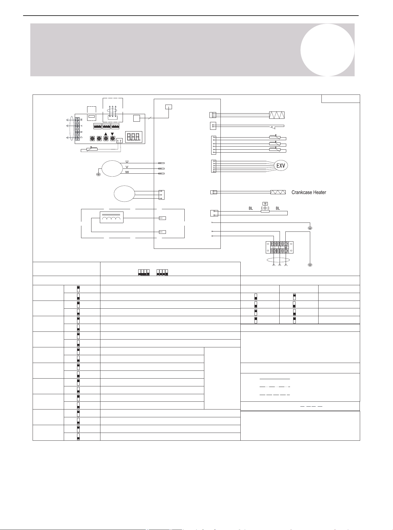
01 02 03 04 05 06 07 08
09 10 11 12 13 14 15 16 17 18
19 20 21 22 23 24 25 26 27 28
29 30 31 32 33 34 35 36 37 38
39 40 41 42 43 44 45 46 47
49
802035000194
Wire Color Code
Factory Settings
SW3-1 SW3-2 MODE
24K (2T)
Factory Settings
Model
SW1-1
Check
RS-485 communication mode
Wire Information
Note 1:
24V control (factory default)
SW1-3
USB upgrade
Reserved (factory default)
SW1-4
System operation mode: Cooling only (factory default)
System operation mode: Heat pump
SW3-3
Accelerated cooling
Normal cooling (factory default)
SW3-4
Accelerated heating
Normal heating (factory default)
36K (3T)
48K (4T)
60K (5T)
SW2-1
Fix timed defrost
Defrosting
control
mode
Auto defrost (factory default)
SW2-2
Timer 30 min
Timer 60 min (factory default)
SW2-3
Powerful defrosting
Normal (factory default)
SW2-4
Thermostat O/B signal is opposite
Normal (factory default)
SW1-2
Display unit: °C & Mpa
Display unit: °F & PSI (factory default)
On
Off
Off
Off
Off
Off
On
On
On
On
On
Off
On
Off
On
Off
On
Off
On
Off
On
Off
On
Off
On
Off
On
Off
Exhaust temp
Outdoor coil temp
HP
CN106
(T3)
(TP/T5)
(T4)
Pressure Sensors
CN10
Power Supply
Outdoor ambient temp
RD
RD
CN7
(DC-FAN)
DC
Motor
W
V
U
YE/GN
YE/GN
GND
Outdoor Display Board
4
CN2(L)
CN1(N)
GND
Comp.
YE/GN
COMP3(W)
COMP2(V)
COMP1(U)
CN8
(DISP)
BL
WH
RD
CN21
(HP)
BL
RD
CN31
(EXV)
Solenoid Valve
EXV
Inductor
CN14
(HEATY)
CN17
(SV2)
CN12
CN11
Outdoor T7 condensing temp
CN3
2 3
KE
SW1
1 4
ON
SW2
KE
ON
2
31 4
SW3
KE
ON
2
31 4
T7
P
Q
E
CN6
K2
K1
K4
K3
SET
CHK
USB
CZ1
RS-485
communication
24V
communication
Factory Connection
Project Connection
Dashed Circle (Optional)
Note: For reference only, the actual wiring diagram shall prevail.
The wiring diagram is for explanation purpose
only and the actual shape of the components
may be different.
On
On
(Factory default)
SW1 SW2
16
Wiring Diagram
RD (RED) OR (ORANGE) BK (BLACK)
BR (BROWN) BL (BLUE) GN (GREEN)
PR (PURPLE) WH (WHITE) GY (GREY)
YE (YELLOW)
Air Conditioner Installation & User Manual
62
17
Cleaning & Maintenance
Cleaning Precautions
Warning:
• Qualified maintenance personnel must carry out the maintenance and cleaning of the outdoor
units.
Caution: Electric Shock
• Before cleaning or maintenance, turn off the unit and disconnect the power supply.
Note:
• Do not use chemicals or chemically treated clothes to clean the unit.
• Do not use benzene, paint thinner, polishing powder, or other solvents to clean this unit.
Be Careful:
• When removing the filter, do not touch the metals parts in the unit. The sharp metals edges
can cut cut.
Pre-Season Inspection & Maintenance
Complete the following at the start of each Heating or Cooling season:
Table 17.1.
Turn off the unit and disconnect the power supply
Check for damaged wires and leaks
Make sure that all air inlets and outlets are not blocked
Air Conditioner Installation & User Manual
63
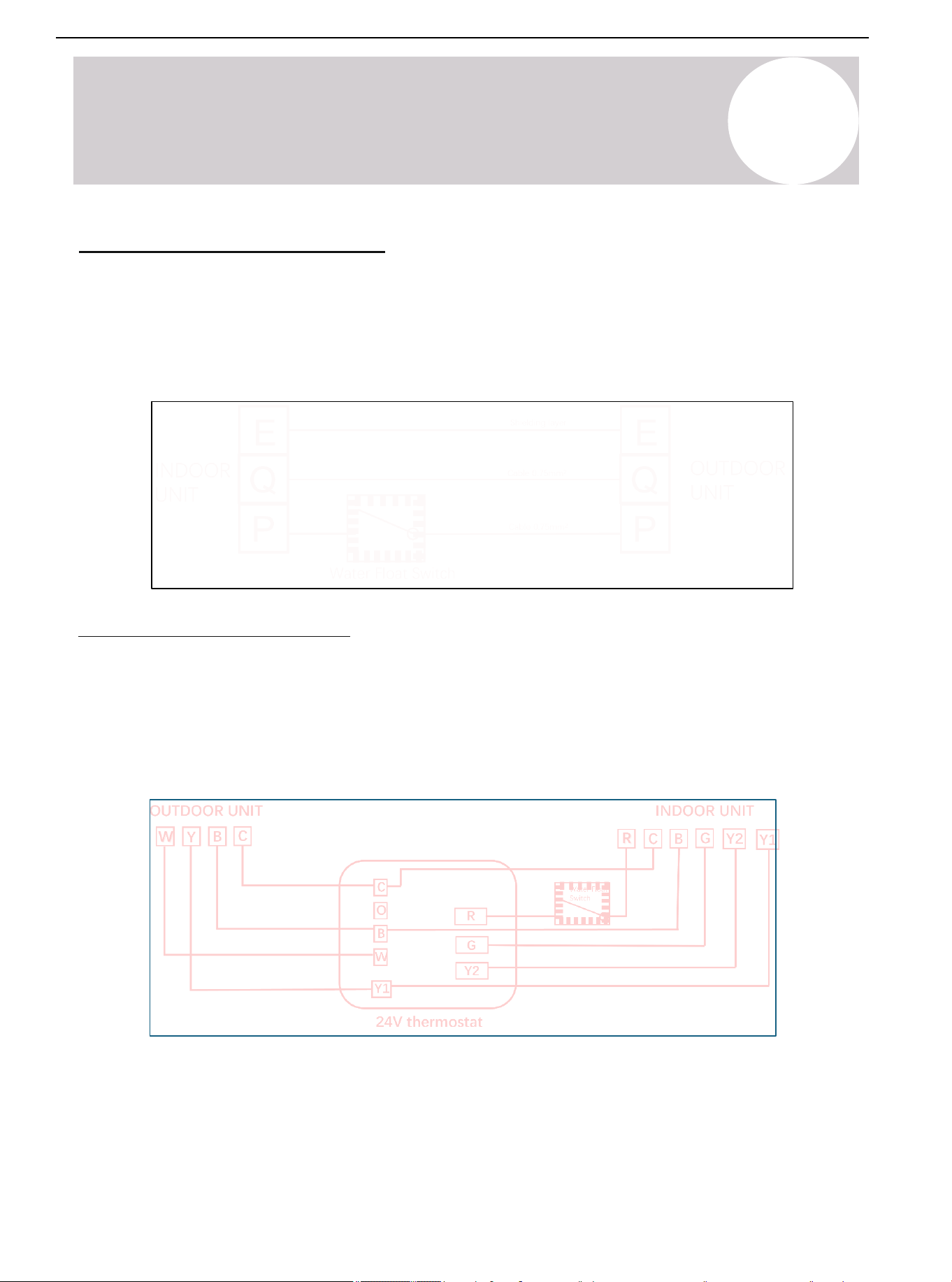
01 02 03 04 05 06 07 08
09 10 11 12 13 14 15 16 17 18
19 20 21 22 23 24 25 26 27 28
29 30 31 32 33 34 35 36 37 38
39 40 41 42 43 44 45 46 47 48
18
Water Float Switch Wiring
RS-485 Communication Mode
The indoor and outdoor units connect to 3
communication lines, P.Q.E. Connect the water float switch between
the "P" communication line. Terminal P's communication line first passes through the water float switch, then to
Terminal P of the outdoor unit.
Refer to the following figure for wiring:
24V Communication Mode
The indoor and outdoor units connect with R/C/Y/B/G via the 24V thermostat. The R terminal is a 24V power
supply. Connect the water float switch to the R signal between the thermostat and indoor unit. When the water
float switch is in overcurrent state, the 24V power supply R and the Y signal of the compressor will disconnect,
causing the compressor to stop operating.
Refer to the following figure for wiring:
Air Conditioner Installation & User Manual
64
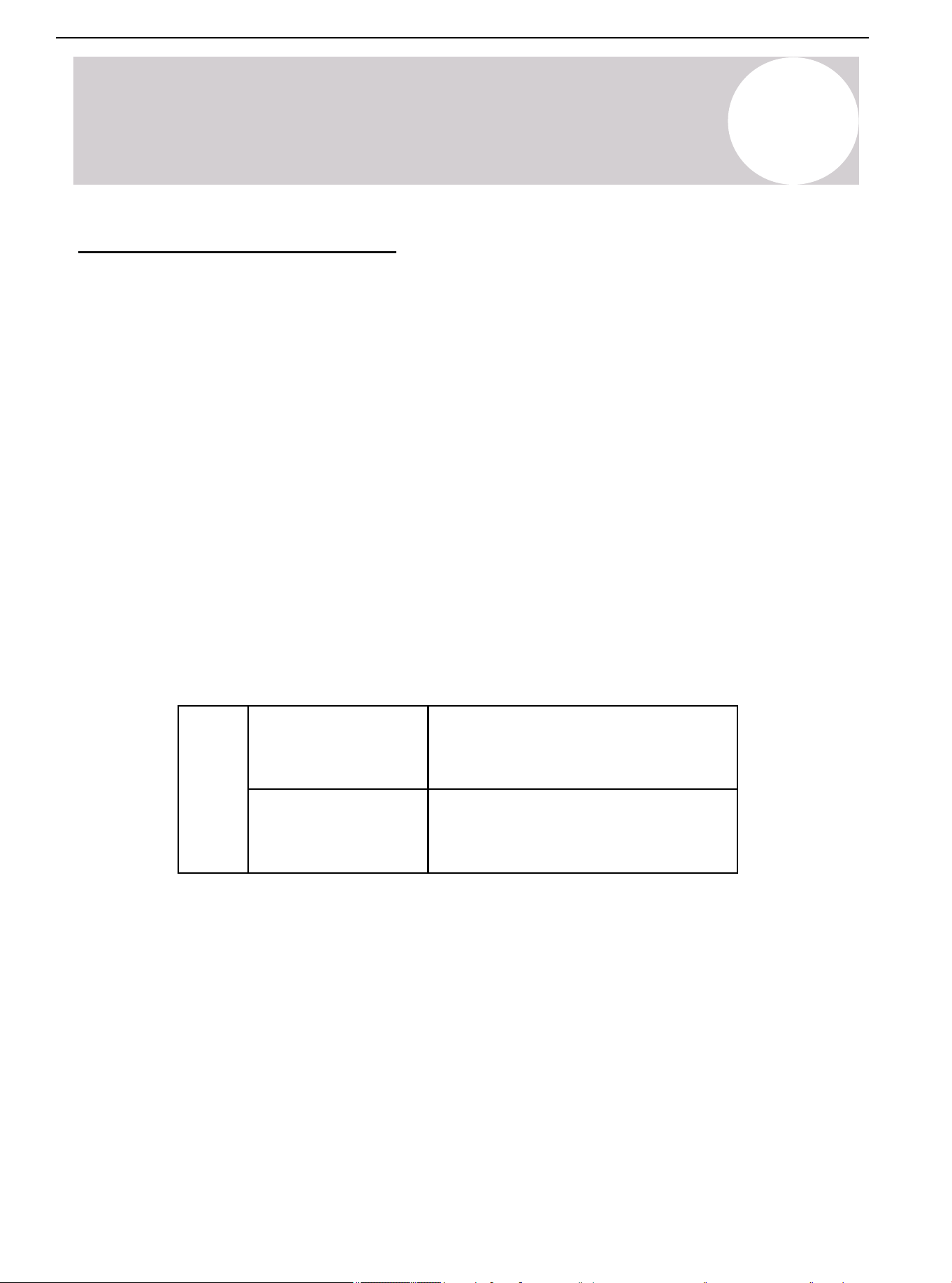
19
RS-485 Wiring & Thermostat
RS-485 Communication Wiring
1) Set the dial switch of the indoor and outdoor units to RS-485 communication mode
Turn the SW1-1 dial switch on the indoor mainboard and the SW1-1 dial switch on the ODU display board to the
"On" position.
Indoor Unit
SW1-1
RS-485 communication mode
24V control (factory default)
Air Conditioner Installation & User Manual
65
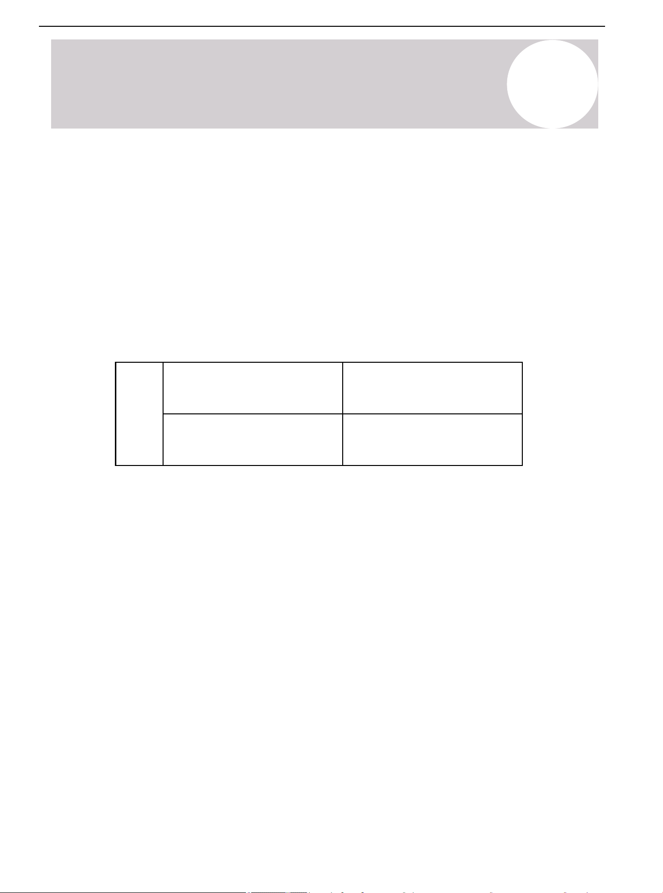
SW1-1
RS-485 communication mode
24V control (factory default)
19
RS-485 Wiring & Thermostat
Outdoor Unit
2) Connect RS-485 Communication Wire
Connect the indoor and outdoor units, P-P, Q-Q, E-E one by one. Use 2-core shielded wires, with the shielding
layer of the cable connected to E.
Note: The wired controller communication cable is provided by the factory. The PQE communication cables for
the IDU and ODU need to be purchased by the customer in the local market.
Air Conditioner Installation & User Manual
66

19
RS-485 Communication Wiring
3) 12V Wire Controller
Note: For detailed operating instructions, refer to the wire controller manual.
Air Conditioner Installation & User Manual
67
20
Product Disposal Guidelines
Special Notice
Disposing of this appliance improperly, or in other natural surr oundings, endangers your
health and is bad for the environment. Hazardous substances may leak into the gr ound water
and enter the food chain. Follow proper disposal protocols.
• Dispose of the appliance at a designated municipal electronic waste collection facility.
• When buying a new appliance, the retailer will take back the old appliance free of charge.
• The manufacturer will take back the old appliance free of charge.
• Sell the appliance to certified scrap metal dealers.
Product Disposal Guidelines
This appliance contains refrigerant and other potentially hazardous materials. When
disposing the appliance, the law requires special collection and treatment. Do not dispose this
product as household waste or unsorted municipal waste.
Remove all refrigerant and oil prior to disposal as outlined within this manual.
When disposing of this appliance, the following options are available:
Air Conditioner Installation & User Manual
68
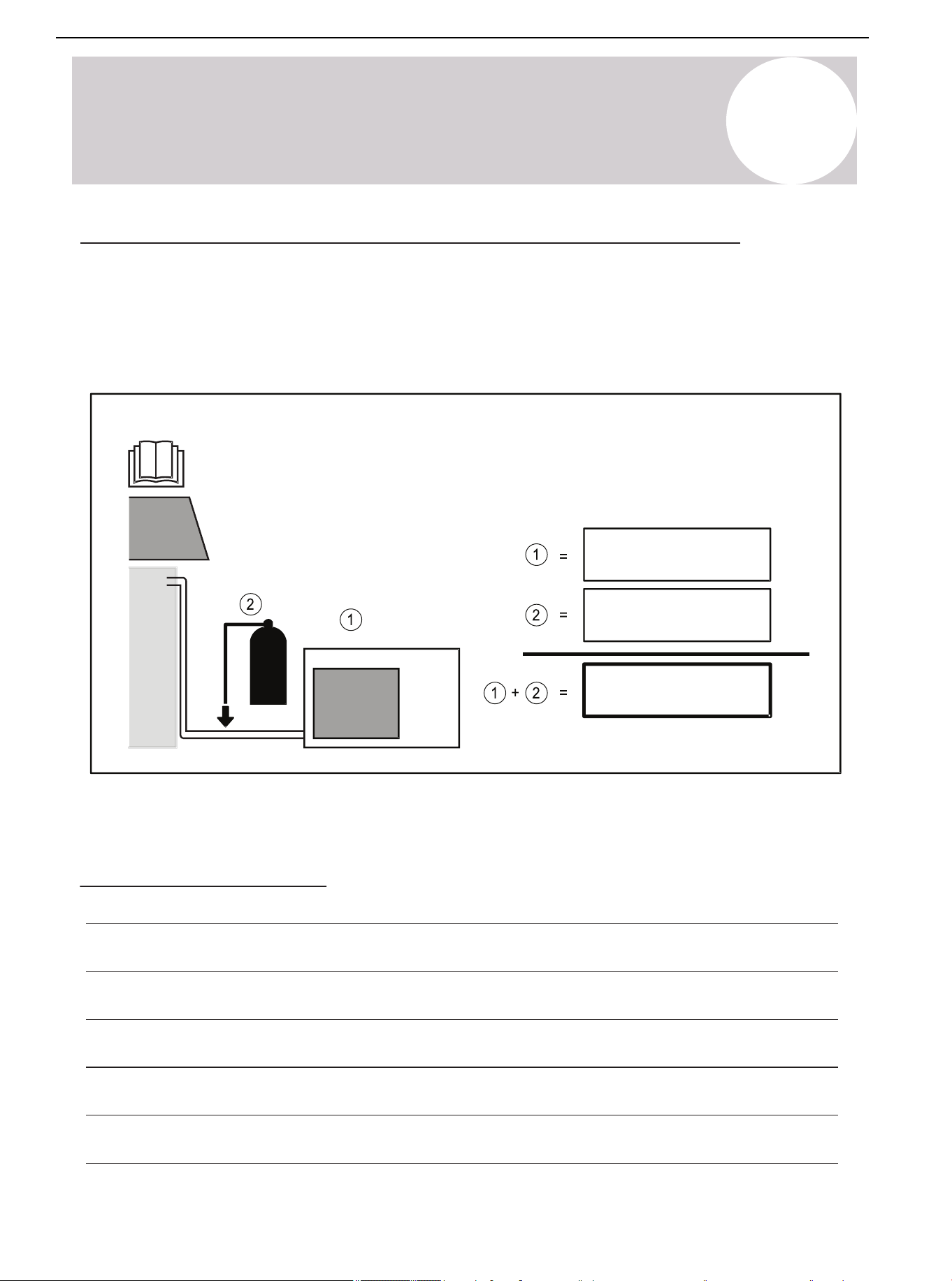
If Refrigerant Has Been Added to the System During Installation
(For the Installer) fill in the following:
1) The factory refrigerant charge of the product (located on the outdoor unit nameplate).
2) The additional refrigerant charged into the product.
1+2) The total refrigerant charge.
We recommend keeping this information handy for future service and maintenance needs.
System Notes
ozs (kg)
ozs (kg)
ozs (kg)
A
Appendix
Air Conditioner Installation & User Manual
69

The design and specifications of this product are subject to change without prior
notice as development continues. Consult with the sales agency or manufacturer
for details.
Refer to the equipment nameplate for all other applicable specifications.
Copyright 2025, Parker Davis HVAC International, LLC., All rights reserved.
is a registered trademark of Parker Davis HVAC International, LLC.
Parker Davis HVAC International
7290 NW 77 Court, Miami, FL 33166 - USA
Tel : (305) 513-4488
Fax : (305) 513-4499
E-mail : [email protected]
Website: www.pdhvac.com
Pioneer product line, parts, and supplies are
available online for convenient ordering at:
www.highseer.com
www.pioneerminisplit.com
Scan the below code to visit our support page
where you can find more installation materials:
70