Installation and Operation Manual
THE EXPERTS IN ROOM AIR CONDITIONING
FA SELECT 115 VOLT FSHSR09B1C, FSHSR12B1C
FA SELECT 208/230 VOLT FSHSR18B3D, FSHSR24B3D,
FA PRO 115 VOLT FPHSR09A1C, FPHSR12A1C
FA PRO 208/230 VOLT FPHSR09A3D, FPHSR12A3D,
FPHSR18A3D, FPHSR24A3D, FSHSR36B3D
Models
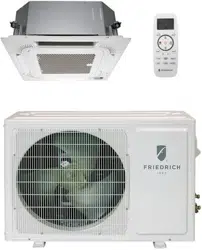
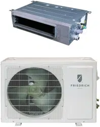
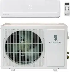
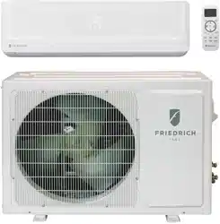
Ductless Split
S
ingle Zone
Outdoor Unit
R-32, R-454B Refrigerant
96111103_00
2
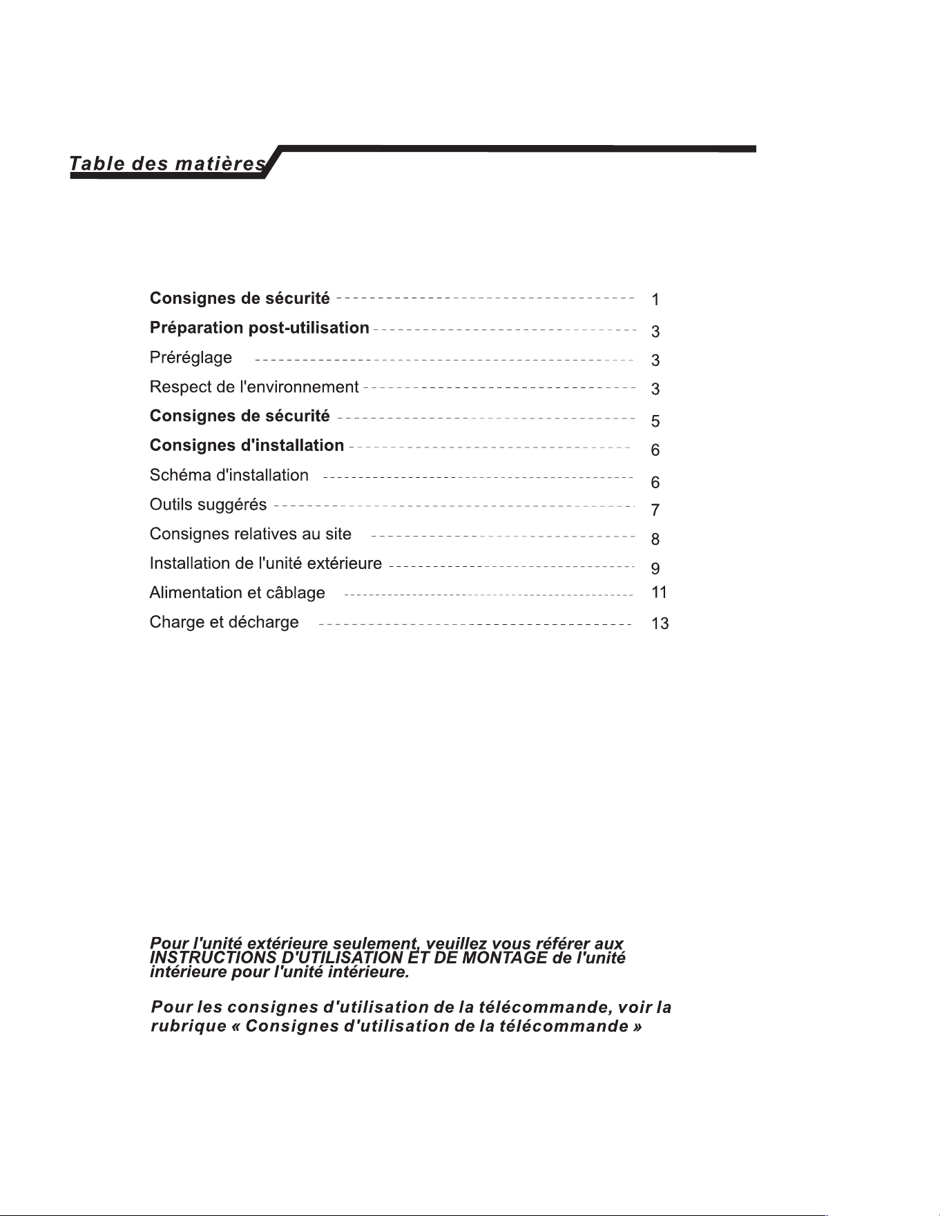
A. IMPORTANT SAFETY AND GENERAL INFORMATION .................3
A.1 Introduction ............................................................................. 3
A.2 • Safety Symbols .....................................................................3
A.4 Importance of a Quality Installation ..................................... 5
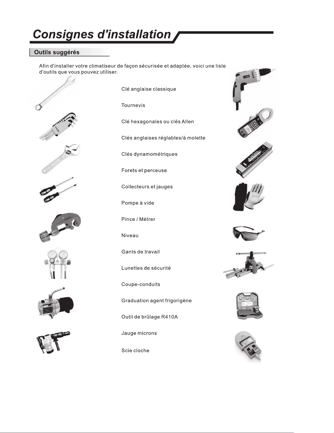
C.1 Tools ..........................................................................................6
C.2 Clearances .............................................................................. 7
C.3 Pre-Installation Checkpoints ................................................. 8
C.4 Install Condensate Drain .......................................................9
C.5 Install Ground Pad or Wall Hangers ................................... 9
C.6 Piping Connections to Outdoor Unit ..................................... 9
E. ELECTRICAL ........................................................................................ 10
E.1 Specifications .........................................................................10
E.2 Wiring Diagrams ..................................................................11
G. LEAK CHECK, CHARGING AND TRIPLE EVACUATION ................12
J. STARTUP AND OPERATION ..............................................................14
J.1 Checklist and Operation Test ...............................................14
ESPAÑOL .................................................................................................. 16
FRANÇAIS ................................................................................................31
Register your Air Conditioner
Model information can be found on the name plate.
Please complete and mail the owner registration card furnished with
this product, or register online at www.friedrich.com.
For outdoor unit only, refer to the indoor unit Installation
and Operation Manual as well as the Remote Control
Operation instructions for additional information.
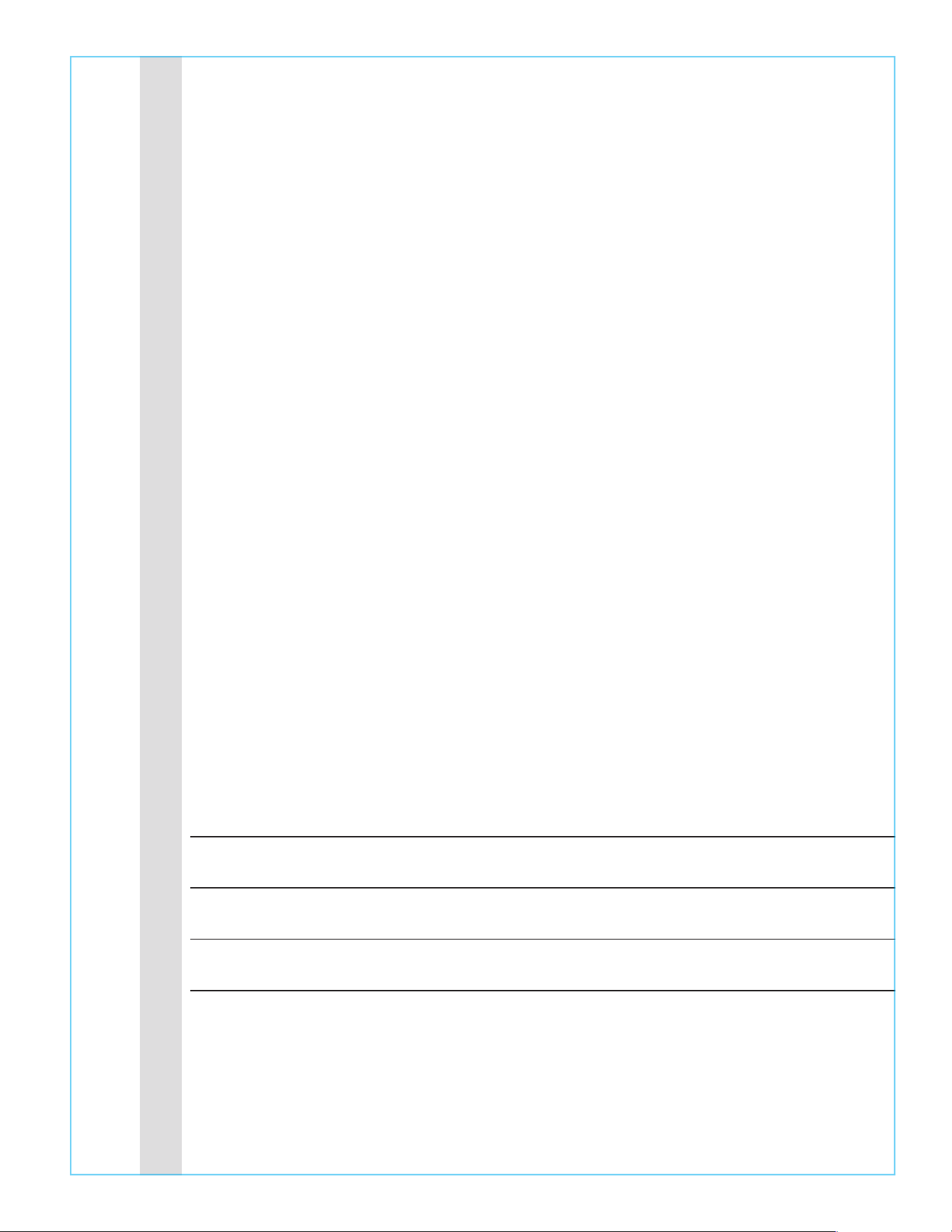
US
C
tection I
The ptecti dee mae tp and stop
e appance the cases listed below.
Outdoor air temperature is over 75
°
F(24
°
C)
HE
ING
Outdoor air tempetu is below -4
°
F(-
2
)
Room temperature is over 80.6
°
F(27
°
C)
COOLING
Outdoor air tempeture is over *115
°
F(46
°
C)
Room temperature is below 70
°
F(21
°
C)
DRY
Room temperature is below 64.5
°
F(18
°
C)
*r Tpical ) Clima conon models, e
tempetu pot is 131"F(55"C) sad of 109"F(43"C).
The mpetu of some pduc is aod bend the
nge. In specic situation, please consult e mehant.
*For R32 erant mode can keep heang at -4
°
F(-20 °C)
outdoor ambient, r R eerant mols n ke
heating at -13
°
F (-25 "C) outdoor ambient. For some mode,
can keep heating even at lower outdoor ambient
e air condioner ns COOUNG or DRY mode
door or dow opened r a long me en la
humidi abo 8,dew may dp do m e ouet.
•
Install the air conditioner at a place that
can bear its weight in order to operate
more quietly.
• Install the outdoor unit at a place where
the air discharged and the operation noise
would not annoy your neighbors.
• Do not place any obstacles in front of the
air outlet of the outdoor unit lest it increases
the noise level.
The protective device will work at following cases.
0 Restaing the unit at once after operation stops or changing mode during operation, you need to
wait 3 minutes.
If all operation has stopped, press ON/OFFbutton again to resta, Timer should be set again
if it has been canceled.
Preheat
At the beginning of the HEING operation, the ailow from the indoor unit is discharged
2-5 minutes later.
Dest
In HE
ING operation the appliance will defrost (de-ice) automatically to raise eiciency.
This procedure usually lasts 2-10 minutes. During defrosting, fans stop operation.
After defrosting completes, it returns to HEATING mode automatically.
-18-
3
A. IMPORTANT SAFETY AND GENERAL INFORMATION
A.1 Introduction
This booklet contains the installation and operating instructions for your Air Conditioning unit. There are some precautions that should be taken
to ensure proper operation. Improper installation can result in unsatisfactory operation or dangerous conditions.
Read this booklet and any instructions packaged with separate equipment required to make up the system prior to installation. Give this booklet
to the owner and explain its provisions. The owner should retain this booklet for future reference.
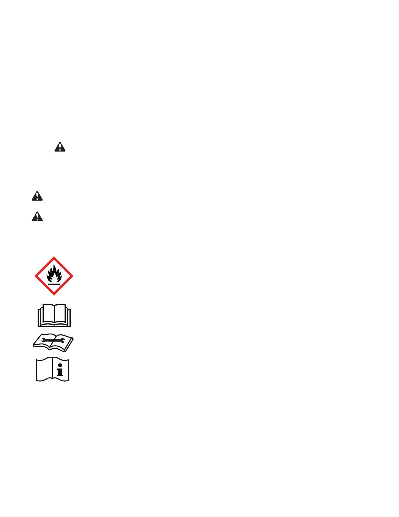
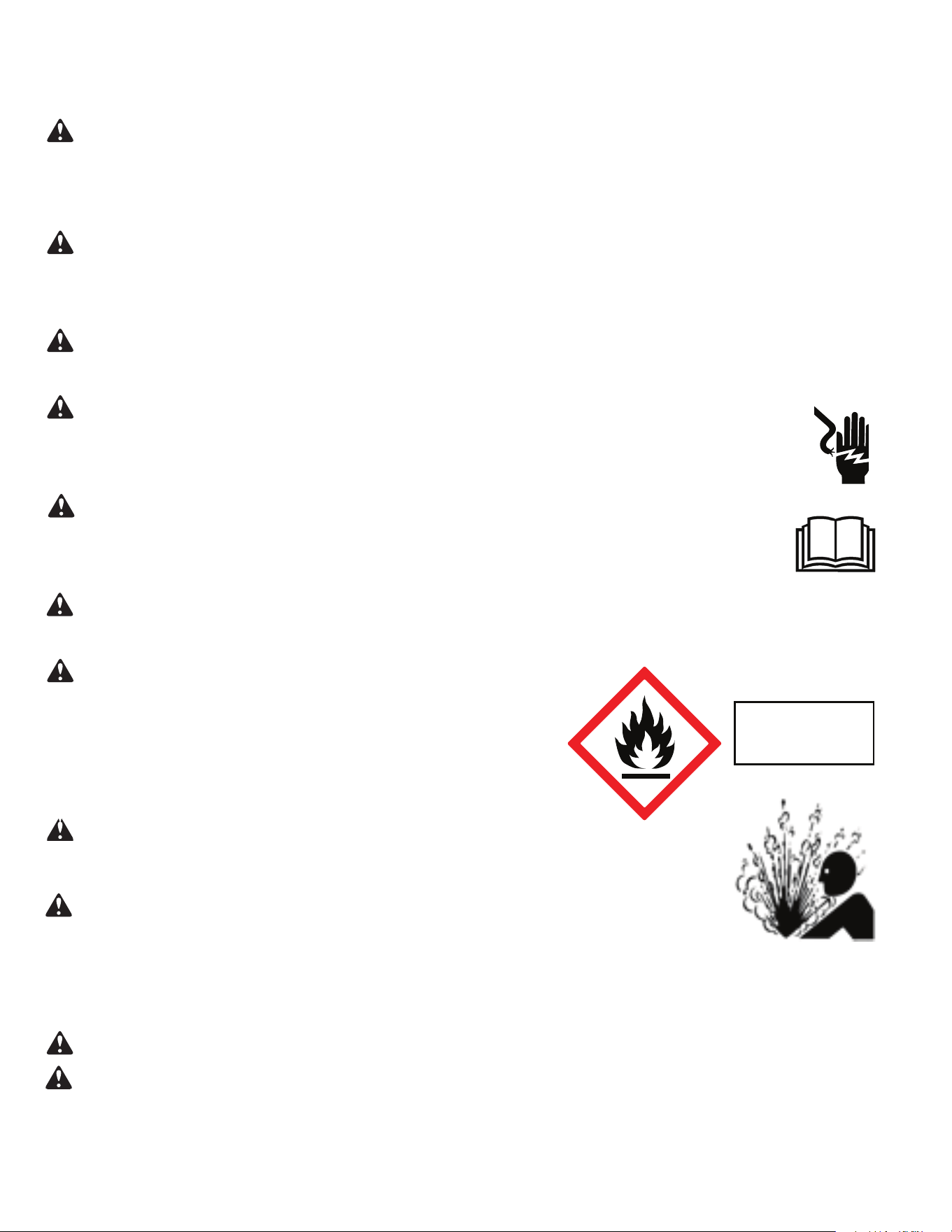
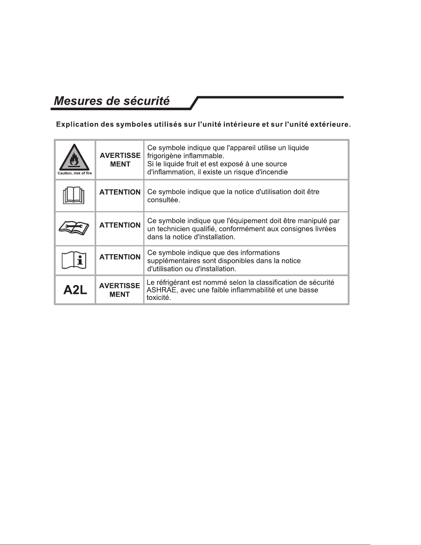
A.2 • Safety Symbols
This symbol indicates that this appliance uses a flammable refrigerant. If the refrigerant is leaked and is exposed to an
external ignition source, there is a risk of fire.
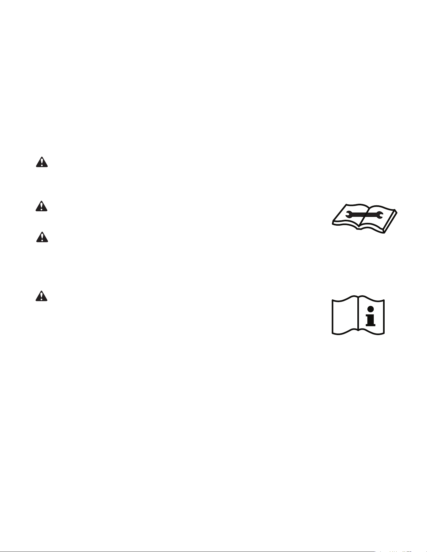
This symbol indicates that the Operation Manual should be read carefully.
This symbol indicates that service personnel should be handling this equipment with reference to the installation manual.
This symbol indicates that information is available such as the Installation and Operation manual, or the Service Manual.
SAFETY IS IMPORTANT
We have provided many important safety messages in this manual and on your appliance. Always read and obey all safety messages.
Indicates a hazard which, if not avoided, can result in severe personal injury or death and damage to product or other
property.
Indicates a hazard which, if not avoided, can result in personal injury and damage to product or other property.
All safety messages will tell you what the potential hazard is, tell you how to reduce the chance of injury, and tell you
what will happen if the instructions are not followed.
NOTICE
CAUTION
WARNING
All safety messages will follow the safety alert symbol with the word “WARNING” or “CAUTION”. These words mean:
This is a safety Alert symbol. This symbol alerts you to potential hazards that can kill or hurt you and others.
Indicates property damage can occur if instructions are not followed.
4
A. IMPORTANT SAFETY AND GENERAL INFORMATION
A.3 • Safety Warnings
WARNING
:
The manufacturer’s warranty does not cover any damage or defect to the air conditioner caused by the attachment
or
use of any components, accessories or devices (other than those authorized by the manufacturer) into, onto or in conjunction with the air
conditioner. You should be aware that the use of unauthorized components, accessories or devices may adversely affect the operation of the
air conditioner and may also endanger life and property. The manufacturer disclaims any responsibility for such loss or injury resulting from
the use of such unauthorized components, accessories or devices.
WARNING
:
This appliance is not intended for use by persons (Including children) with reduced physical, sensory or mental
capabilities, or lack of experience and knowledge, unless they have been given supervision or instruction concerning use of the appliance by
a person responsible for their safety.
Children should be supervised to ensure that they do not play with the appliance.
WARNING
:
The maximum altitude for this appliance is 2,000 meters(6,562 feet).
Do not use above 2,000 meters(6,562 feet).
WARNING: Electrical Shock Hazard
Disconnect all power to the unit before starting maintenance. All electrical connections and wiring MUST be installed by a qualified
electrician and conform to all local codes which have jurisdiction. Failure to do so can result in property damage, severe electrical
shock or death.
WARNING:
Read Installation Manual
Read this manual thoroughly prior to equipment installation or operation. It is the installer’s resposibility to properly apply
and install the equipment. Installation must be in conformance with the NFPA 70-2023 national electric code or current edition,
International Mechanic code 2021 or current edition, and any other local or national codes.
WARNING:
Safety First
Do not remove, disable, or bypass this unit’s safety devices. Doing so may cause fire, injuries, or death.
WARNING: This Product uses R-32 or R-454B Refrigerant
Do not use means to accelerate the defrosting process or to clean, other than those
recommended by the manufacturer.
The appliance shall be stored in a room without continuously operating ignition sources
(for example: open flames, an operating gas appliance or an operating electric heater.
Do not pierce or burn.
Be aware that refrigerants may not contain an odor.
WARNING:
Refrigeration System under High pressure
Do not puncture, heat, expose to flame or incinerate. Only certified refrigeration technicians should service this
equipment. R454B systems operate at higher pressures than R22 equipment. Appropriate safe service and
handling practices must be used.
CAUTION:
Do Not Operate Equipment During Active Stages Of
Construction
To ensure proper operation, Friedrich requires that all equipment is not operated during active construction phases. This includes active stages
of completing framing, drywalling, spackling, sanding, painting, flooring, and moulding in the equipment’s designated conditioning space. The
use of this equipment during construction could result in premature failure of the components and/or system and is in violation of our standard
warranty guidelines. The opera
tion of newly installed equipment during construction will accelerate the commencement and/or termination of
the warranty period.
WARNING:
Keep all air circulation and ventilation openings free from obstruction.
WARNING:
The unit should not be in contact with any equipment that will transmit vibration to the unit. Any excessive vibration or
pulsation to the unit could result in damage to the refrigerant tubing.
Refrigerant
Safety Group
A2L
5
A. IMPORTANT SAFETY AND GENERAL INFORMATION
A.4 Importance of a Quality Installation
Optimal system performance and longevity depend upon a quality and proper installation. Failure to properly install this unit could result in
undesirable operation and subsequent faults and potential failures.
Carefully follow all guidelines listed in the manual and industry best practices. Conform to all local code requirements. Contact your local
technical representative with any questions or concerns.
Due to continuing research in new energy-saving technology, all information in this manual is subject to change without notice.
Upon receiving the unit, inspect it for any damage from shipment. Claims for damage, either shipping or concealed, should be filed immediately
with the shipping company. IMPORTANT: Check the unit model number, Cooling size, electrical characteristics, and accessories to determine if
they are correct.
WARNING:
Check the unit power cord and make sure the cord is protected from wear, corrosion, excessive pressure, vibration,
sharp edges, or any other adverse environmental effects. It is recommended that the cord is checked for any potential damage when filter
maintenance is performed. If the supply cord is damaged, it must be replaced by the manufacturer, its service agent or similarly qualified
persons in order to avoid a hazard.
WARNING:
If the unit appears damaged,or if a refrigerant leak is suspected, do not install.
Contact a licensed repair person to perform a leak check on the unit.
WARNING:
Under no circumstances shall potential sources of ignition be used in the searching
for or detection of refrigerant leaks. A halide torch (or any other detector using a naked flame) shall not be used. The following leak detection
methods are deemed acceptable for all refrigerant systems. Electronic leak detectors may be used to detect refrigerant leaks but, in
the case of FLAMMABLE REFRIGERANTS, the sensitivity may not be adequate, or may need re-calibration. (Detection equipment
shall be calibrated in a refrigerant-free area.) Ensure that the detector is not a potential source of ignition and is suitable for the refrigerant
used. Leak detection equipment shall be set at a percentage of the LFL.
WARNING:
Service of this product (aside from filter maintenance) shall only be performed by
trained service personnel. This includes:
• Opening of any ventilated Any tubing or refrigerant circuit work.
• Opening of any sealed components.
• Enclosures beyond the hinged door for filter cleaning.
• Disposal or decommissioning of the unit.
NOTICE: This manual is subject to change without notice.
Scan this QR code to be linked to the Friedrich professional support page where you can locate the most up to date Installation and
operation Manual, Remote Control Manual, and Service Manual.
6
C. INSTALLATION OF THE UNIT
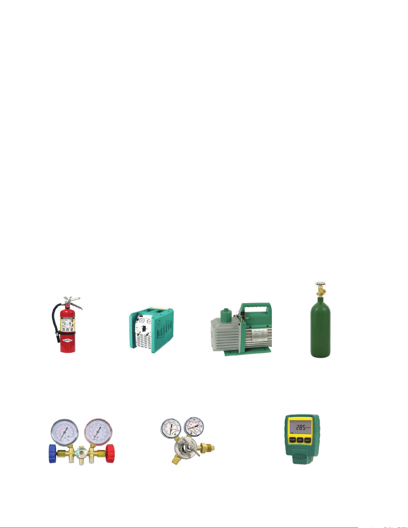
Figure C.1 (Tools)
Verify with tool manufacturers that all tools used during servicing of the refrigerant are non-sparking and can be used with A2L Refrigerants.
No halide torches for leak testing.
Refrigerant monitors or detectors must be used to detect refrigerant in the work area.
• R-32 A2L Refrigerant Recovery System.
• Vacuum Pump rated for A2L refrigerant (capable of 300 microns or less vacuum.)
• Nitrogen bottle with purging and pressurizing capabilities up to 550 psi.
• Non-Sparking (Not Halide)Electronic Leak Detector rated for detecting A2L refrigerant.
• Digital refrigerant scale Refrigeration Gauges rated for A2L Refrigerants with temp scales for R-32 refrigerant.
• Gauge Manifold (Right handed threads).
• A2L compatible Vacuum Gauge capable of 300 microns or less.
• Nitrogen regulator for purging and testing, rated to 800 psi. (Capable of low psi flow)
• Pipe tubing cutter.
• Refrigerant recovery cylinder. (Flammable A2L label)
• Ventilation fan.
• Class ABC fire extinguisher.
• Purge hose fittings
• Flaring tool
Recovery Machine
Vaccum Pump
Nitrogen
ABC Fire Extinguisher
Guage Manifold
Nitrogen Regulator
Vacuum Guage
C.1 Tools
7
C. INSTALLATION OF THE UNIT
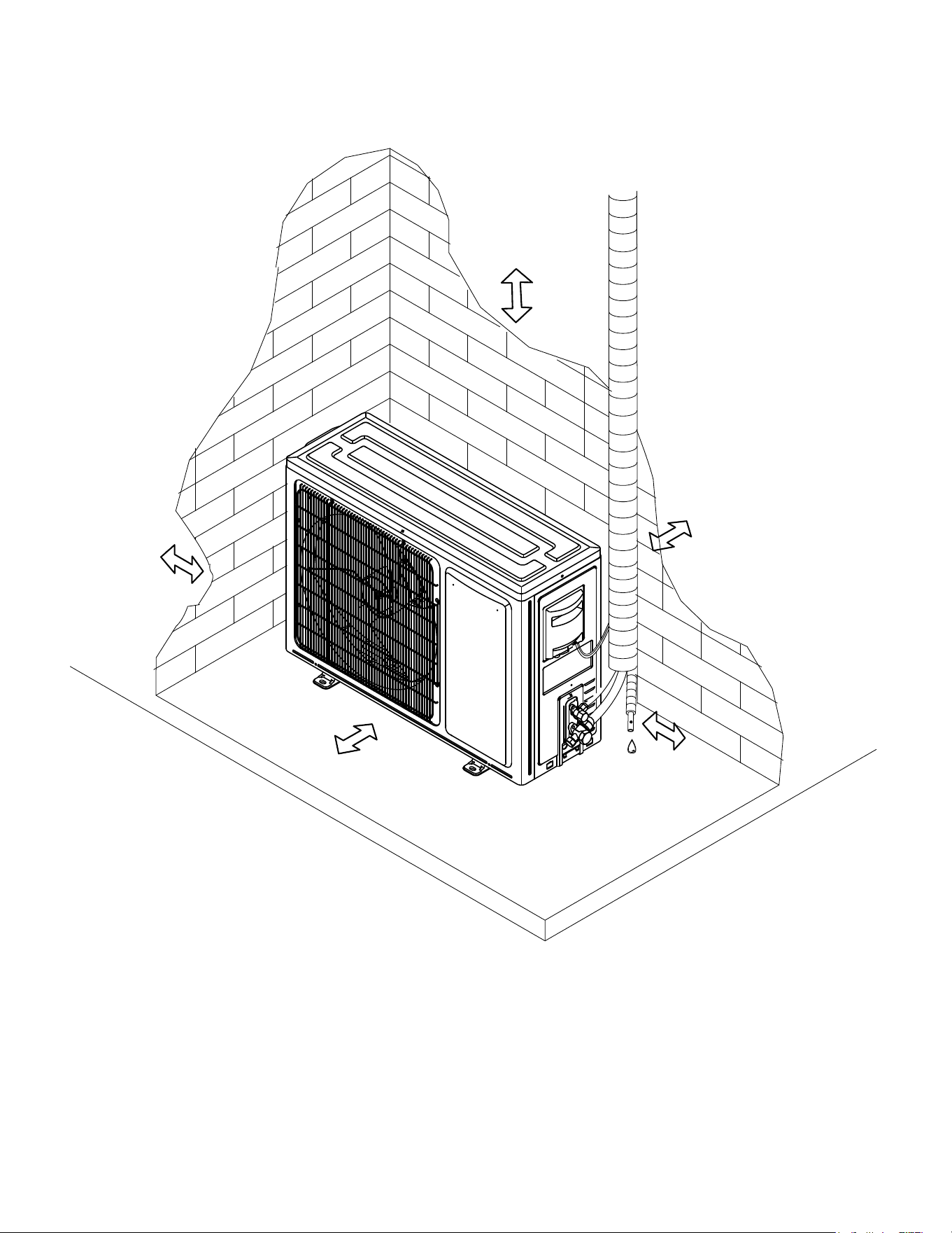
C.2 Clearances
Figure C.2
Air intake distance from the
wall should be over 10 inches.
Over 10 inches
Air outlet distance from the wall should be over 20 inches>
Distance from any obstacle should be over
20 inches from the top of the unit
8
C. INSTALLATION OF THE UNIT
C.3 Pre-Installation Checkpoints
• Location is convenient to install and well ventilated.
• Avoid installing it where flammable gas could leak.
• Keep the required distance from walls and other obstacles.
• Keep the outdoor unit away from grease and debris.
• Avoid installing it by the roadside where there is a risk of mud-
dy water.
• Install on a fixed base where it is not subject to increased
operation noise.
• Ensure there is no blockage of the air outlet.
• Avoid installing under direct sunlight, in an aisle or sideway,
or near heat sources and ventilation fans.
• Keep away from flammable materials, thick oil fog, and wet or
uneven places.
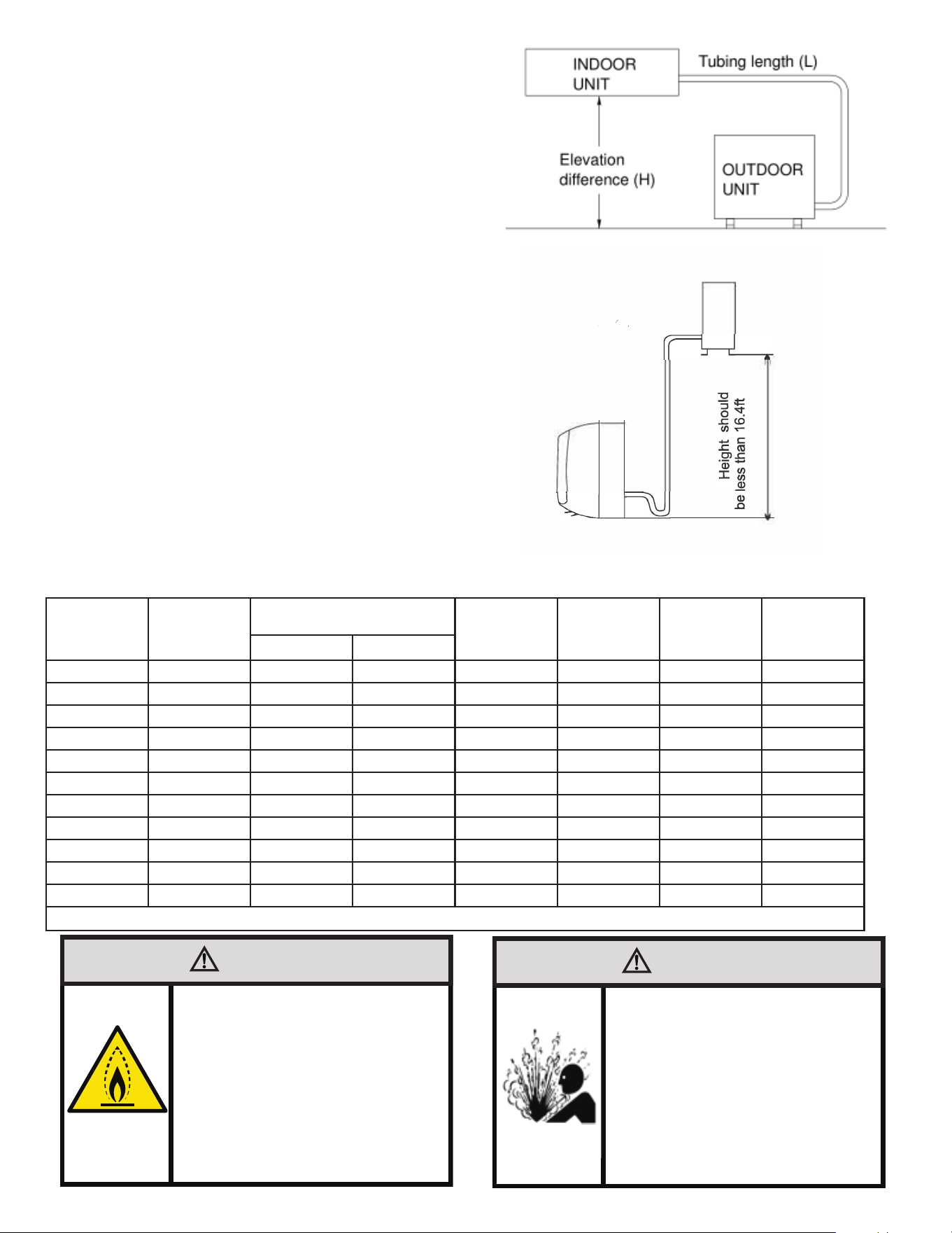
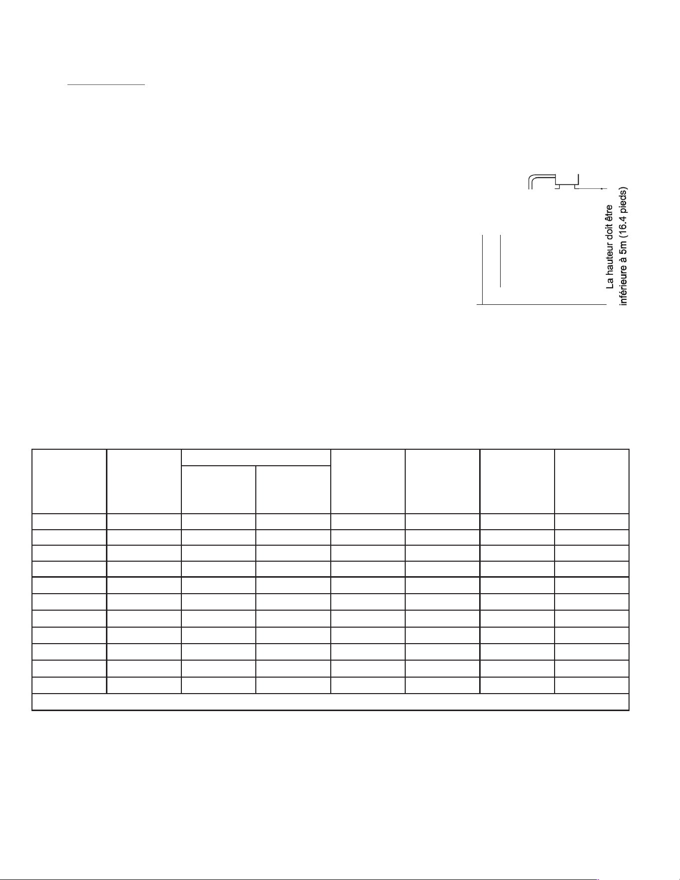
• Outdoor unit comes pre-charged with refrigerant for 25 ft of line
set.
• If the indoor unit is installed more than 16 ft in elevation below
the outdoor unit, an oil trap should be installed every 16 ft in
elevation drop.
NOTE:
1. To avoid storing too much oil in the oil bend, the oil bend
should be as short as possible.
2. The horizontal piping should be sloped down along the re-
frigerant flow direction, to bring the oil back to compressor.
The slope should be between 1/200 and 1/250.
• Indoor unit can not be installed more than 50 feet in elevation
above the outdoor unit.
• Refer to refrigerant Leak Check, Charging, and Evacuation
section of the manual.
Model
Refrigerant
Pre-Charge
Pipe Size
Standard
Length (ft)
Max.
Elevation
H (ft)
Max. Length
L (ft)
Additional
Refrigerant
(oz/ft)
LIQUID GAS
FPHSR09A1C 33.5 oz 1/4" 3/8" 25 50 66 .22
FPHSR09A3D 35.2 oz 1/4" 3/8" 25 50 66 .22
FSHSR09B1C 21.2 oz 1/4" 3/8" 25 50 66 .22
FPHSR12A1C 35.3 oz 1/4" 3/8" 25 50 66 .22
FPHSR12A3D 38.1 oz 1/4" 3/8" 25 50 66 .22
FSHSR12B1C 21.9 oz 1/4" 3/8" 25 50 66 .22
FPHSR18A3D 53 oz 1/4" 1/2" 25 50 100 .22
FSHSR18B3D 45.9 oz 1/4" 1/2" 25 50 100 .22
FPHSR24A3D 70.6 3/8" 5/8" 25 50 100 .32
FSHSR24B3D 47.6 3/8" 5/8" 25 50 100 .32
FSHSR36B3D 72.4 3/8" 5/8" 25 50 100 .43
Table C.3.3
WARNING
Fire Hazard
A2L refrigerant is classified as mildly
flammable. Temperatures on surfaces that may
be exposed to leakage of FLAMMABLE
REFRIGERANTS shall not exceed 1292°F
WARNING
Refigeration System
Under High Pressure
Do not puncture, heat, expose to flame or
incinerate.
Only certified refrigeration technicians should
service this equipment.
R-32 and R-454B systems operate at higher
pressures than R22 equipment.
Appropriate safe service and handling
practices must be used.
Only use gauge sets designed for use with
R32 and R-454B.
Do not use standard R22 gauge sets..
/
Site Instructions
Site for Outdoor Unit
• Where it is convenient to install and well ventilated.
• Avoid it where ammable gas could leak.
•
Keep the required distance apart from the wall.
• Keep the outdoor unit away from greasy dirt, vulcanization gas exit
.
•
Avoid installing it by the roadside where there is a risk of muddy
water.
•
A xed base where it is not subject to increased operation noise.
• Where there is not any blockage of the air outlet.
• Avoid installing under direct sunlight, in an aisle or sideway,
or near heat sources and ventilation fans. Keep away from
ammable materials, thick oil
and wet or uneven places.
Indoor unit
Outdoor unit
Outdoor unit is higher than indoor unit
• In case the pipe length is more than the refrigerant should be charged additionally, according
to below table.
Model
Required amount of
additional refrigerant (Oz)
9K-18K
0.7
24K
1.0
If the height or pipe length is out of the scope of the table, please consult the merchant.
of indoor unit refers to indoor unit manual.
-7-
Figure C.3.1
Figure C.3.2
9
C. INSTALLATION OF THE UNIT
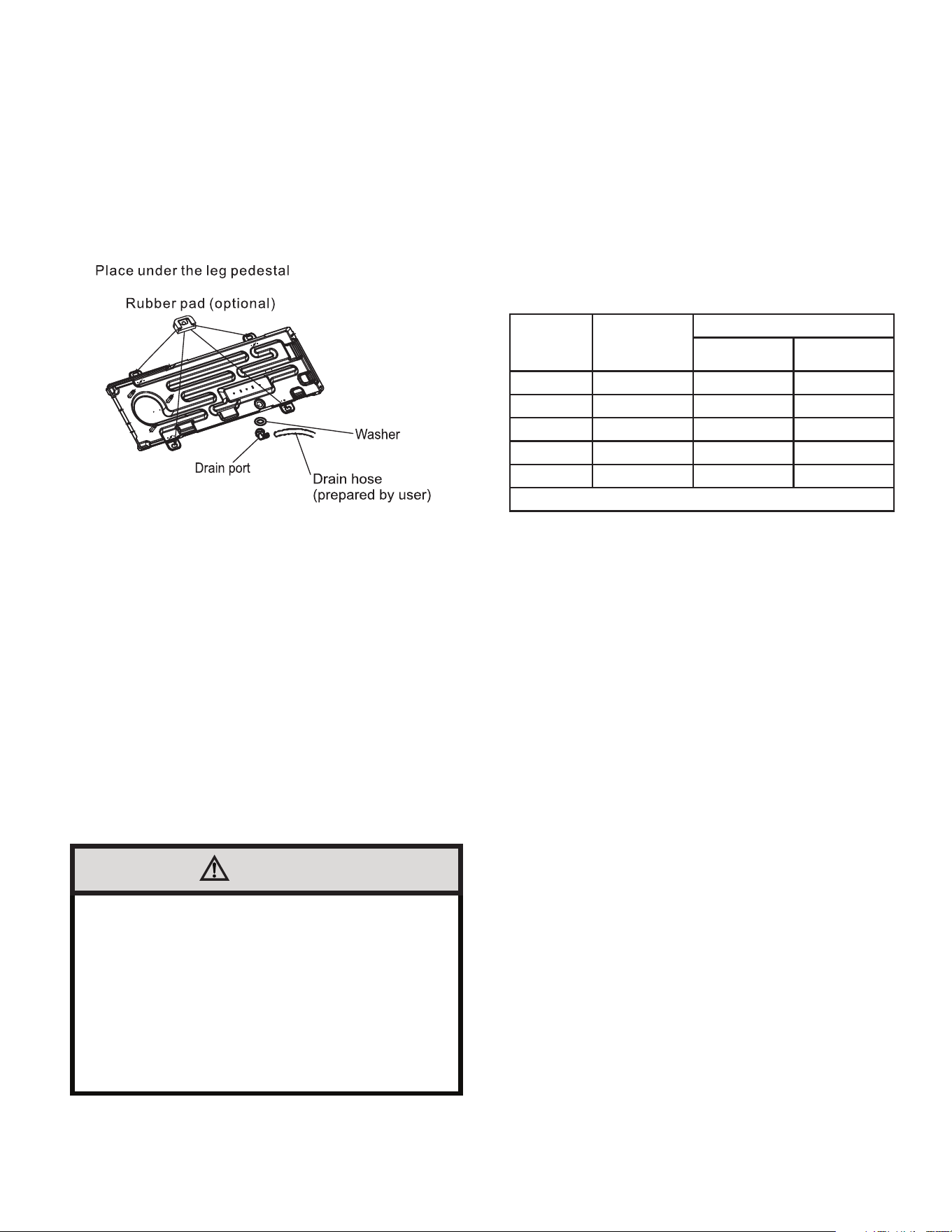
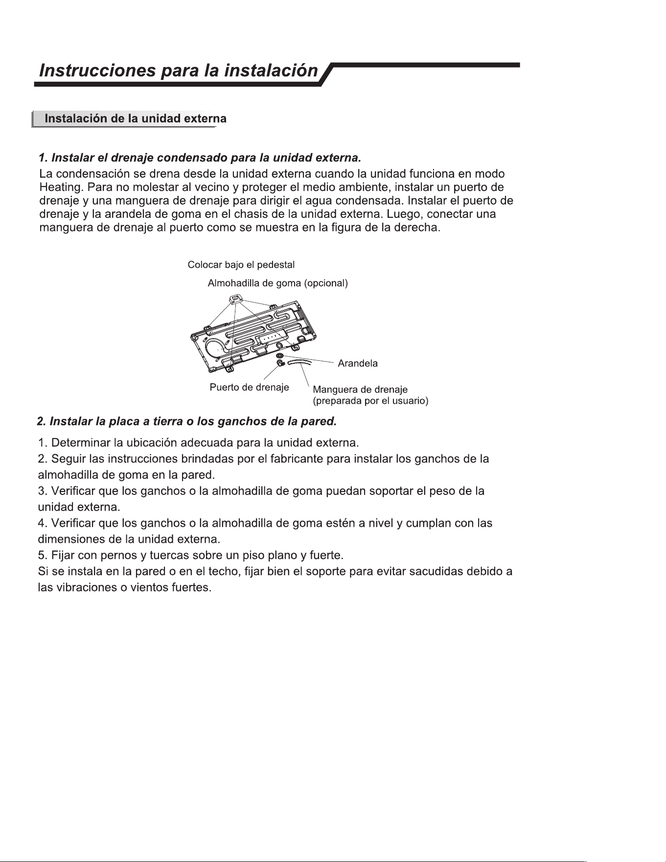
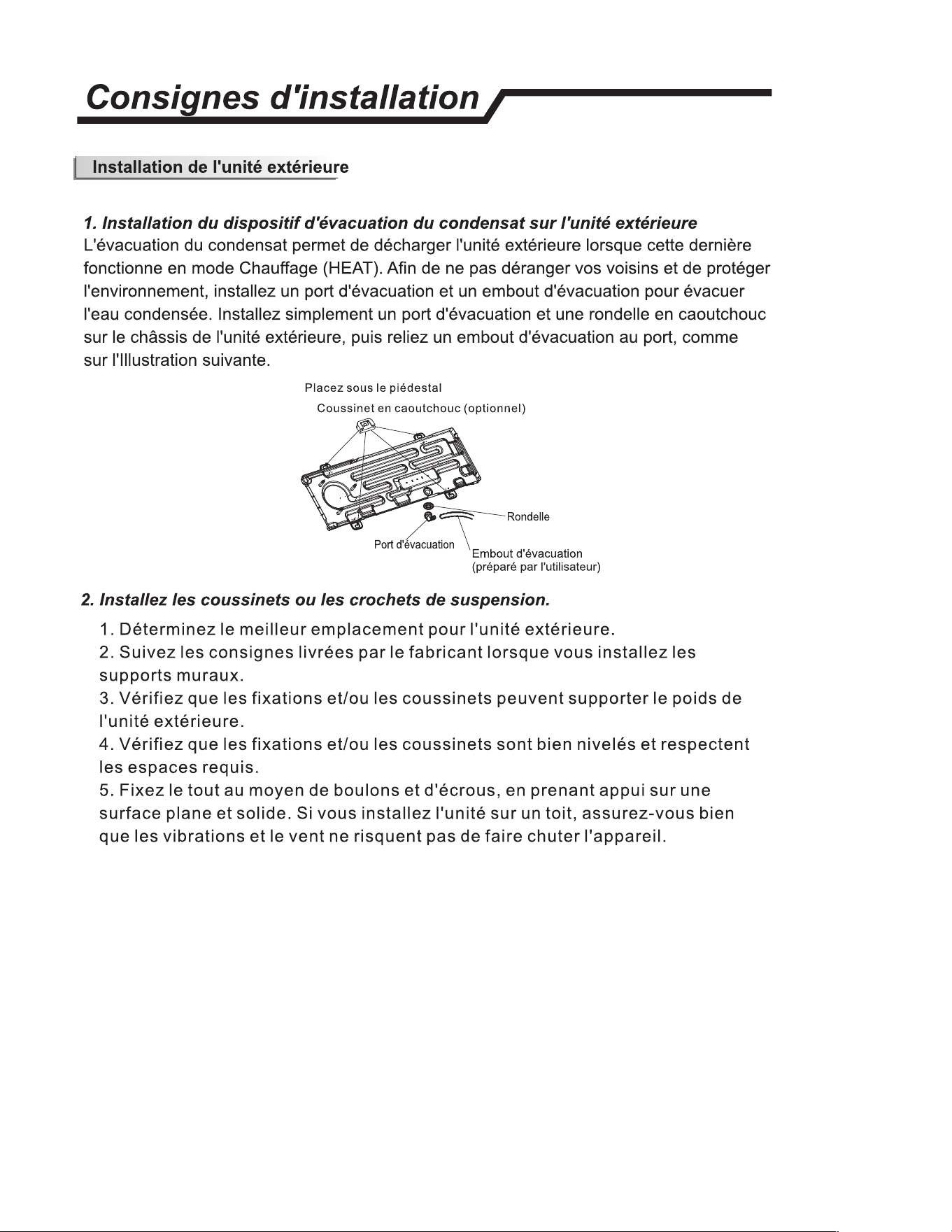
C.4 Install Condensate Drain
Install Condensate Drain for Outdoor Unit
The condensate drains from the outdoor unit when the unit operates
in heating mode.
Install a drain port and a drain hose to direct the condensate water.
Just install the drain port and rubber washer to the chassis of the
outdoor unit, then connect a drain hose to the port. See Figure C.3
Figure C.4
C.5 Install Ground Pad or Wall Hangers
1. Refer to section C.1 and Section C.2 to identify proper unit
location.
2. Follow all instructions provided by manufacturer for installing
wall hangers rubber pad .
3. Verify the wall hangers or rubber pad can safely support the
weight of the outdoor unit.
4. Verify the wall hangers or rubber pad is level and meets all
outdoor dimensional clearance.
5. Attach with bolts and nuts tightly on a flat and strong floor.
If installed on the wall or roof, make sure to attach the support well
to prevent it from shaking due to serious vibration or strong wind .
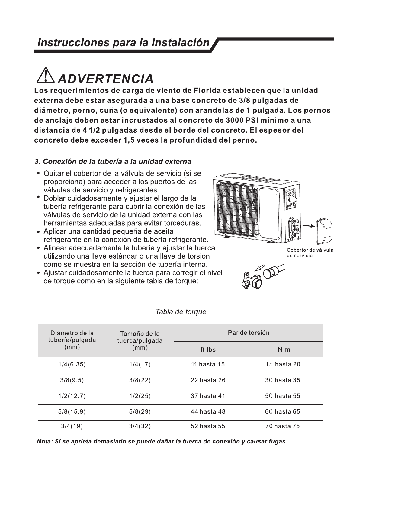
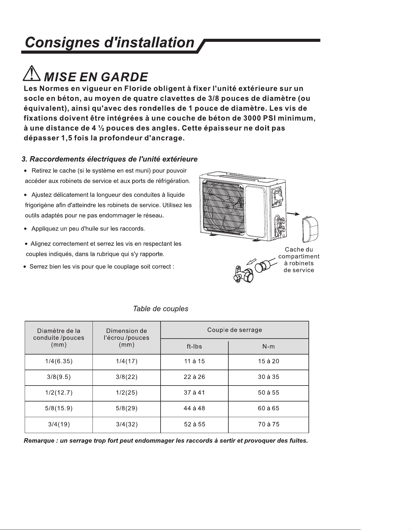
C.6 Piping Connections to Outdoor Unit
1. Remove service valve cover( if provided) to access the service
valves and refrigerant ports.
2. Carefully bend and adjust length of refrigerant pipes to meet
outdoor unit service valves connection with proper tools to avoid
kinks.
3. Apply a small amount of refrigerant oil to the flare connection on
the refrigerant pipe.
4. Properly align piping and tighten flare nut using a standard
wrench and a torque wrench as shown in the indoor piping section.
5. Carefully tighten flare nuts to correct torque level referring to the
following Torque Table:
"Pipe
diameter
/inch"
"Nut Size
/inch"
Tightening Torque
ft-lbs N-m
1/4 1/4 11 to 15 15 to 20
3/8 3/8 22 to 26 30 to 35
1/2 1/2 37 to 41 50 to 55
5/8 5/8 44 to 48 60 to 65
3/4 3/4 52 to 55 70 to 75
Caution: Over tightening may damage flare connections and cause leaks.
Table C.6
WARNING
Florida wind load requirements state that outdoor unit
must be anchored to concrete pad using four 3/8-in
diameter power wedge bolt plus{or equivalent)
with 1-in diameter fender washers. Anchor bolts must
be embedded into 3000 PSI minimum concrete at a
distance of 41/2- in from any concrete edge. The
concrete thickness must exceed 1.5 times the anchor
depth.
10
Insllation Insctions,
l Pr and ng
nnng of e Ca
• Indoor Unit
Ft n
inal
(Inse)
nne the er to e indr unit nnng
the wis the inals on the ntrol indidually
in aan with e outdr unit nn.
N: For mels, it sa m the in
nn the indr unit inal.
�����
�
��
bl
• Ouoor Unit
1) move the ble m e un by loosenlng
the s. Conne the wi e telnals on the ntl
indidually per circuit diagram posted on inside of
access door.
2) S e r on e ntl
with ble clamp.
3) Reinll e ble s boa the original ion
th e sc.
4) U a gnized uit bker n e er
u and e unit. A dlsn de to adua
dinn all supply lin must d.
uon:
Indr unit
Chis
Our unit
1. Never il have an individual pr ciit slly r e air nditioner.
2. Always r to the rcuit diagm d on a inside e a dr for wiring.
3. Con that e ble this is as sied in the er u specition.
4. Chk e s and make su at they a all gh sned ar ble nneon.
5.
su insll an leakage ci bker in t or ist aas.
S
E. ELECTRICAL
E.1 Specifications
WARNING
Electrical Shock Hazard
Always ensure power is
disconnected before attempting
to connect wires.
WIRE SIZE
Use ONLY wiring size recommended by
the National Electric Code (NEC) for single
outlet branch circuit.
FUSE/CIRCUIT
BREAKER
Use ONLY type and size fuse or HACR
circuit breaker indicated on unit’s rating
plate. Proper current protection to the
unit is the responsibility of the owner.
GROUNDING
Unit MUST be grounded from branch cir-
cuit to unit, or through separate ground
wire. Be sure that branch circuit or gen-
eral purpose outlet is grounded. Do NOT
use an extension cord.
ELECTRICAL
DISCONNECT
Ensure an electrical disconnect is
installed according local and national
electrical codes
Model Wire Diameter(AWG)
Interconnecting Wire
between Indoor and
Outdoor Unit
Main Power Supply To Outdoor Unit
Wire Size MOP (Rating of Over
current Device)
MCA (Minimum Circuit
Ampacity)
FPHSR09A1C 14-4 AWG 600V THHN Size according to Local
and National Electrical
codes.
25A 16A
FPHSR09A3D 14-4 AWG 600V THHN 15A 9.5A
FSHSR09B1C 14-4 AWG 600V THHN 25A 14.6A
FPHSR12A1C 14-4 AWG 600V THHN 25A 16A
FPHSR12A3D 14-4 AWG 600V THHN 15A 10.5A
FSHSR12B1C 14-4 AWG 600V THHN 25A 15.4
FPHSR18A3D 14-4 AWG 600V THHN 30A 20A
FSHSR18B3D 14-4 AWG 600V THHN 20A 14.5A
FPHSR24A3D 14-4 AWG 600V THHN 35A 22A
FSHSR24B3D 14-4 AWG 600V THHN 35A 21A
FSHSR36B3D 14-4 AWG 600V THHN 40A 25.8A
Table E.1
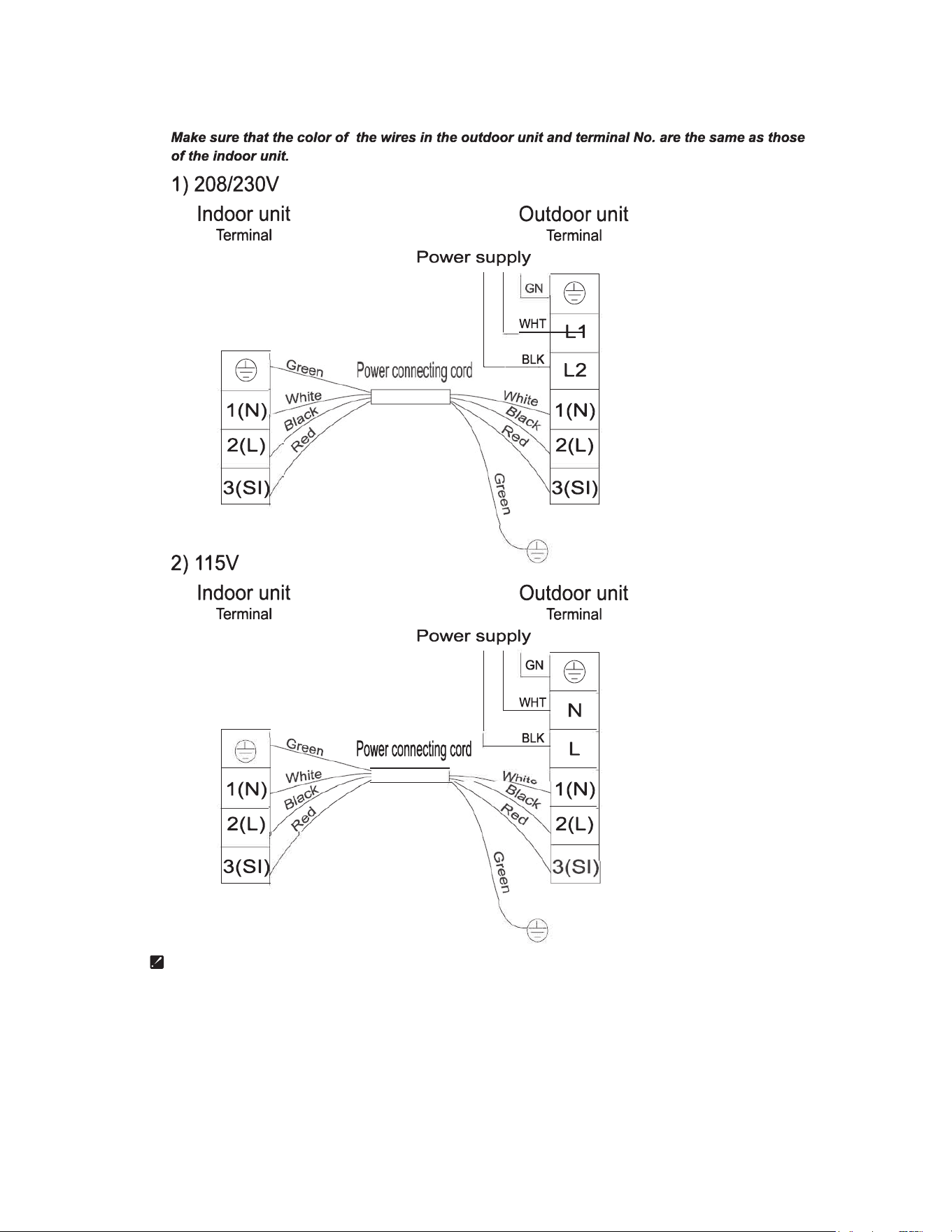
Indoor Unit
Connect the power cord to the indoor unit by connecting the wires to the
terminals on the control board individually in accordance with the outdoor unit
connection.
Note: For some models, it is necessary to remove the cabinet to connect to the
indoor unit terminal.
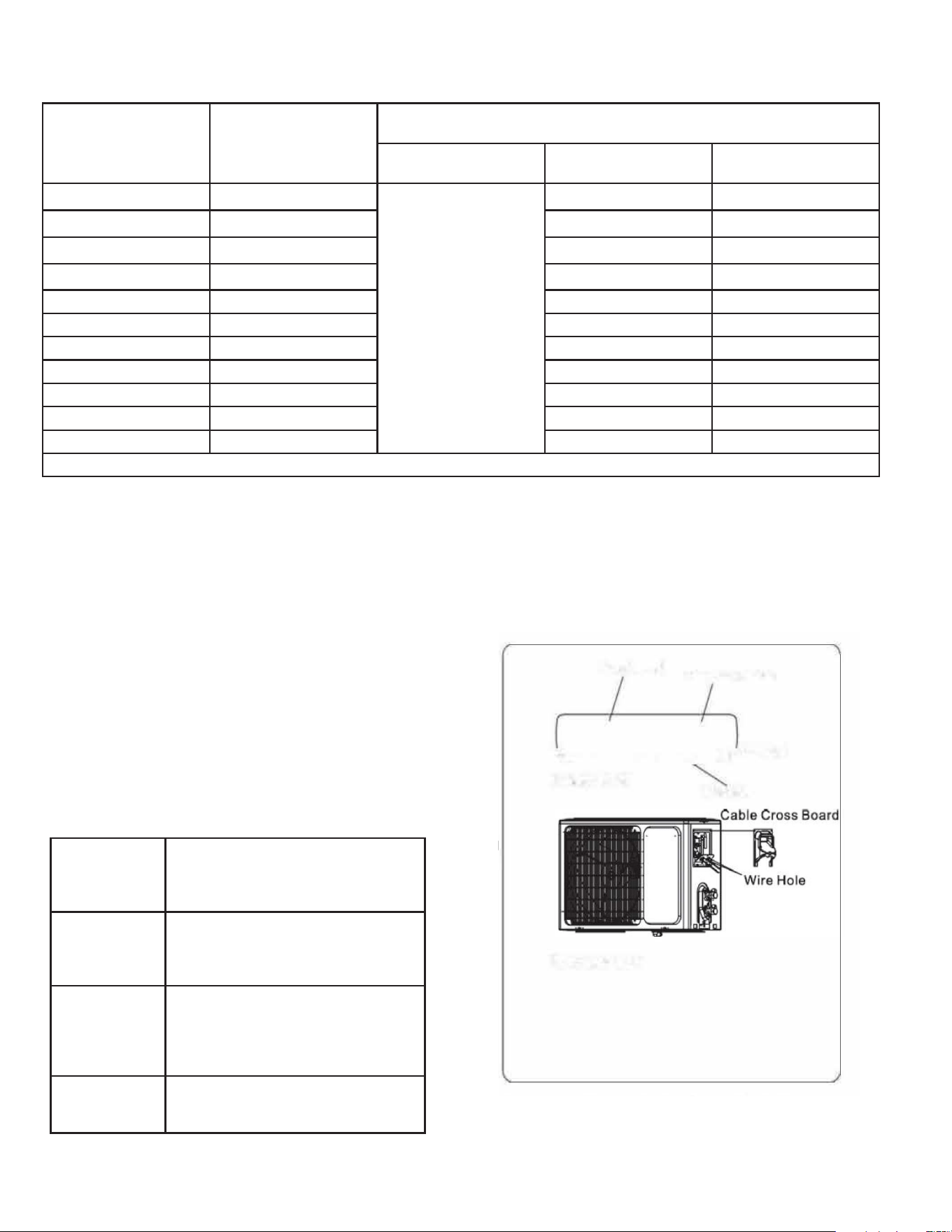
Outdoor Unit
1. Remove the cable cross board from the unit by loosening the screw. Connect
the wires to the terminals on the control board individually per circuit diagram
posted on inside of access door. Refer to Figure E.2.
2. Secure the power cord onto the control board with cable clamp.
3. Reinstall the cable cross board to the original position with the screw.
4. Use a recognized circuit breaker between the power source and the unit. (Refer
to Table E.1. An electrical disconnect must be installed according to local and
national codes. Refer to Table E.1.
Figure E.2
11
E. ELECTRICAL
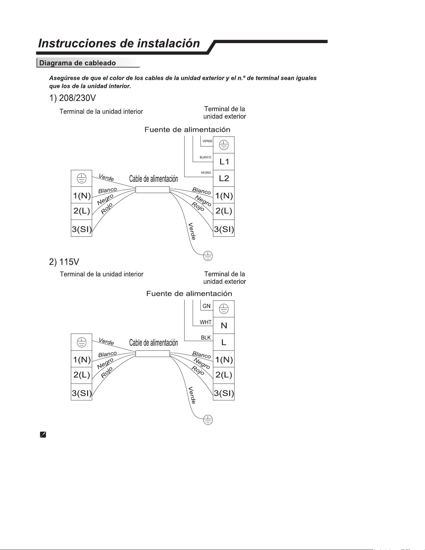
Diagram is reference only, actual product terminals should be followed.
E.2 Wiring Diagrams
12
G. LEAK CHECK, CHARGING AND TRIPLE EVACUATION
Warning:
No ignition sources: No person carrying out work in relation to a
REFRIGERATING SYSTEM which involves exposing any pipe work shall
use any sources of ignition in such a manner that it may lead to the risk
of fire or explosion. All possible ignition sources, including cigarette
smoking, should be kept sufficiently far away from the site of installation,
repairing, removing and disposal, during which refrigerant can possibly
be released to the surrounding space. Prior to work taking place, the
area around the equipment is to be surveyed to make sure that there are
no flammable hazards or ignition risks.
Ventilated Area: Ensure that the area is in the open or that it is adequately
ventilated before accessing the refrigerant in the system or conducting
any hot work. A degree of ventilation shall continue during the period
that the work is carried out. The ventilation should safely disperse any
released refrigerant away from the work area or external to building
envelope.
During Repairs To Sealed Components: All power must be removed from
the equipment being worked on prior to any removal of sealed covers,
etc. If it is absolutely necessary to have an electrical supply to equipment
during servicing, then a constant leak detector shall be located at the
most critical point to warn of a potentially hazardous situation.
Checks And Repairs To Electrical Devices:
• Repair and maintenance to electrical components shall include
initial safety checks and component inspection procedures. If a fault
exists that could compromise safety, then no electrical supply shall
be connected to the circuit until it is satisfactorily dealt with. If the
fault cannot be corrected remove power supply to unit. DO NOT
OPERATE.
• Initial safety checks shall include:
•That capacitors are discharged: this shall be done in a safe
manner to avoid possibility of sparking;
•That no live electrical components and wiring are exposed while
charging, recovering or purging the system;
•Verify unit is properly grounded.
• Particular attention shall be paid to the following to ensure that
by working on electrical components, the casing is not altered in
such a way that the level of protection is affected. This shall include
damage to cables, excessive number of connections, terminals not
made to original specification, damage to seals, incorrect fitting of
glands, etc.
• Ensure that the apparatus is mounted securely.
• Ensure that seals or sealing materials have not degraded to the
point that they no longer serve the purpose of preventing the
ingress of flammable atmospheres. Replacement parts shall be in
accordance with the manufacturer’s specifications.
•
The following is a list of important considerations when working with
R-32 or R-454B equipment:
• R-32 or R-454B pressure is similar to R-410A and approximately
60% higher than R-22 pressure.
• R-32 or R-454B cylinders must not be allowed to exceed 125˚F, they
may leak or rupture.
• R-32 or R-454B must never be pressurized with a mixture of
compressed air, it may become MORE flammable.
• Servicing equipment and components must be specifically designed
for use with R-32 or R-454B and dedicated to prevent contamination.
• Manifold sets must be equipped with gauges capable of reading 750
psig (high side) and 200 psig (low side), with a 500-psig low-side
retard.
• Gauge hoses must have a minimum 750-psig service pressure
rating.
• Recovery cylinders must have a minimum service pressure rating
of 400 psig, (DOT 4BA400 and DOT BW400 approved cylinders).
• POE (Polyol-Ester) lubricants must be used with R-32 or R-454B
equipment.
• To prevent moisture absorption and lubricant contamination, do not
leave the refrigeration system open to the atmosphere for extended
periods of time.
• If unit refrigerant is low, recover the refrigerant, evacuate, and
recharge unit to nameplate amount.
• If there is any amount of refrigerant in the system charge from the
low side.
• Always charge by liquid inverted.
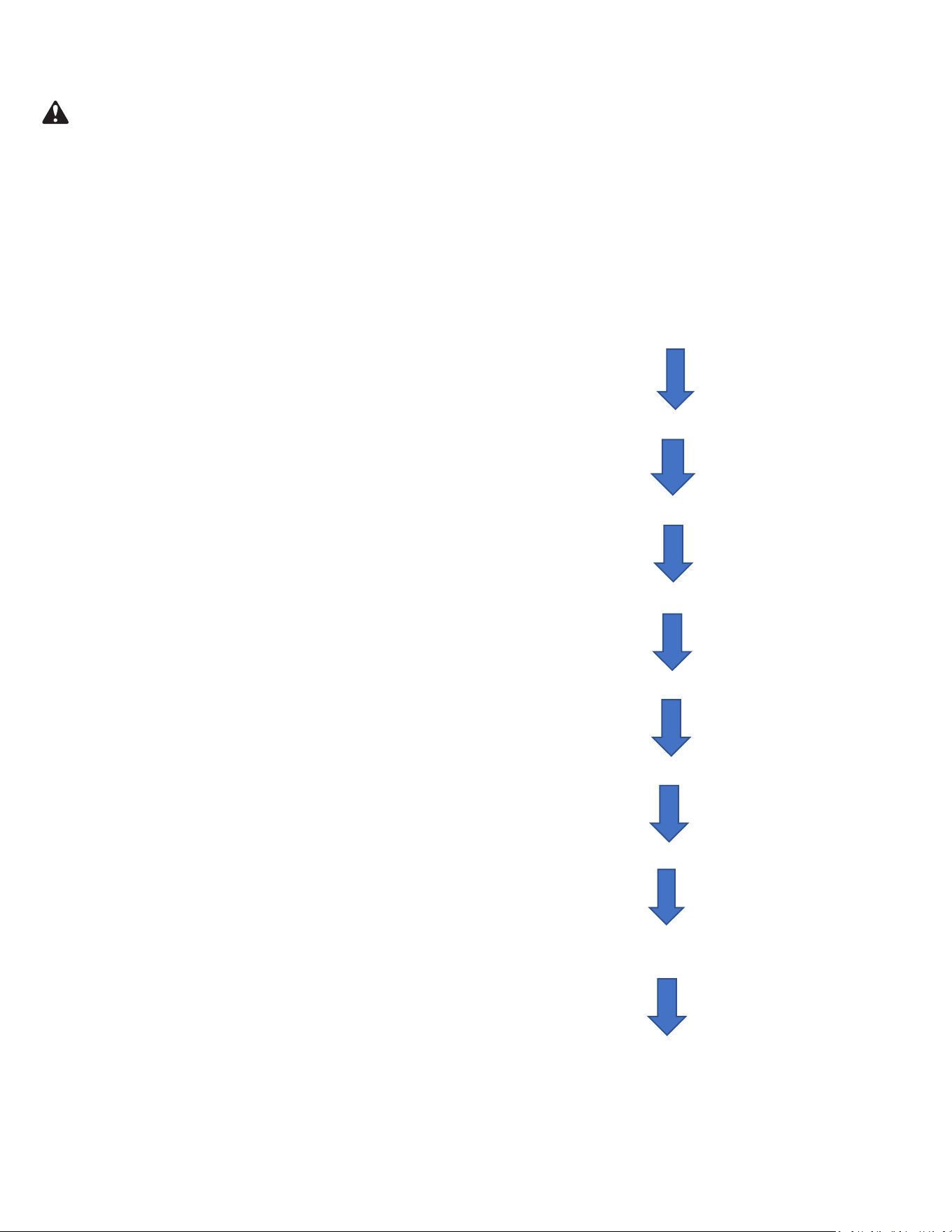
WAIT
EVACUATE
BREAK VACUUM WITH DRY NITROGEN
CHARGE SYSTEM
EVACUATE
WAIT
EVACUATE
CHECK FOR TIGHT, DRY SYSTEM
(IF IT HOLDS A VACUUM)
BREAK VACUUM WITH DRY NITROGEN
Figure G.1
13
G. LEAK CHECK AND CHARGING AND TRIPLE EVACUATION
Friedrich requires all installations are Leak Checked and Evacuated in accordance to the “triple evacuation” process. This process promotes a dry tight
refrigeration system before opening the service valves. It recommended that a single port refrigeration manifold and hoses rated over 31.5psi be used.
Refrigeration hose valves, along with a vacuum pump and micron gauge, must be used to ensure the system can be vacuumed and held under 500
microns. Check all equipment and hoses for proper usage and leaks before beginning.
1. 1st Nitrogen Pressure Test:
Ensure all refrigeration connections are properly flared, secured, and torqued to their respective settings.
Pressurize the system with nitrogen to 550psi. Soap all connections with an approved refrigerant leak detection solution.
The pressure in the system must hold for one hour respective to the environmental conditions and should not vary less than 540psi. If pressure can not
be adequate held, check integrity of flares and torque specifications. Once pressure is held adequately, purge the nitrogen charge to system pressure of
5-10psi. DO NOT RETURN TO ATMOSPHERIC PRESSURE.
2. 1st Vacuum Micron Test:
Connect hoses and vacuum pump to the outdoor unit as shown in Fig. 436. Start the vacuum pump and vacuum to 1000 microns. Close the valve to the
vacuum pump and check for micron rise for 15 minutes. If microns rise to near atmospheric pressure, there is a potential leak; repeat step 1. If microns
rise over 5000, the system is very wet and will require further nitrogen purges.
3. 2nd Nitrogen Break:
Once the system holds below 5000 microns, reconnect the nitrogen tank break the system vacuum with 30-50psi of nitrogen. Wait 5 minutes, then purge
to 5-10psi. DO NOT RETURN TO ATMOSPHERIC PRESSURE.
4. 2nd Vacuum Micron Test:
Reconnect vacuum pump and gauge and begin evacuation. Vacuum system to 500 microns. Close vacuum valve and check for micron rise. Vacuum
should hold under 1000 microns. Repeat steps 3 and 4 until achieved.
5. 3rd Nitrogen Break:
Once the system holds below 1000 microns, reconnect the nitrogen tank break the system vacuum with 30-50psi of nitrogen. Wait 5 minutes, then purge
to 5-10psi. DO NOT RETURN TO ATMOSPHERIC PRESSURE.
6. 3rd Final Vacuum Micron Test:
Reconnect vacuum pump and gauge and begin evacuation. Vacuum system to 300 microns. Close vacuum valve and check for micron rise. Vacuum
should hold under 500 microns. Repeat steps 3 and 4 until achieved. Once held under 500 microns, the system is considered dry and tight.
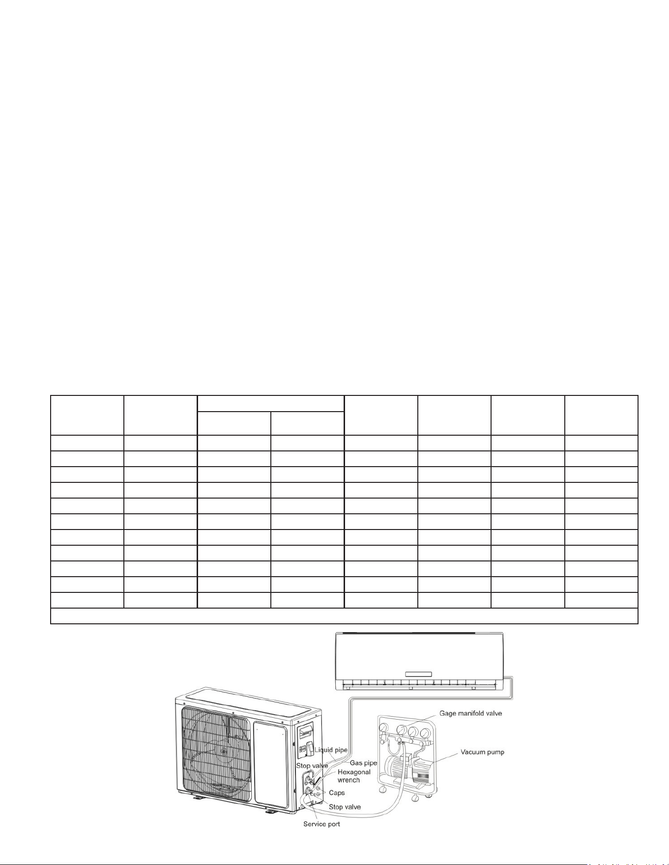
7. Charging the system:
Unscrew Service Valve Caps to expose the inner hexagon head. Use an allen-head spanner or service wrench with appropriate adapter to
release the refrigerant into the system. If the calculated line set length is over 2 ft, weight in the additional charge with an approved refrigerant scale
as needed. Refer to Table G.1.
Capacity
(Btu/h)
Refrigerant Pre-
Charge
Pipe Size
Standard
Length (ft)
Max.
Elevation
H (ft)
Max. Length
L (ft)
Additional
Refrigerant
(oz/ft)
LIQUID GAS
FPHSR09A1C 33.5 oz 1/4" 3/8" 25 50 66 .22
FPHSR09A3D 35.2 oz 1/4" 3/8" 25 50 66 .22
FSHSR09B1C 21.2 oz 1/4" 3/8" 25 50 66 .22
FPHSR12A1C 35.3 oz 1/4" 3/8" 25 50 66 .22
FPHSR12A3D 38.1 oz 1/4" 3/8" 25 50 66 .22
FSHSR12B1C 21.9 oz 1/4" 3/8" 25 50 66 .22
FPHSR18A3D 53 oz 1/4" 1/2" 25 50 100 .22
FSHSR18B3D 45.9 oz 1/4" 1/2" 25 50 100 .22
FPHSR24A3D 70.6 3/8" 5/8" 25 50 100 .32
FSHSR24B3D 47.6 3/8" 5/8" 25 50 100 .32
FSHSR36B3D 70.6 3/8" 5/8" 25 50 100 .43
Table G.2
Figure G.3
14
J. STARTUP AND OPERATION
J.1 Checklist and Operation Test
Present the owner or operator of the equipment with the Installation &
Operation Manual, all accessory installation instructions, and the name,
address, and telephone number of the Authorized Friedrich Warranty
Service Company in the area for future reference if necessary. Inspect
the unit for any damage to the coils and tubing that could cause a leak.
NOTICE
This unit is certified to operate in cooling mode under these maximum
conditions. Any operation beyond these conditions may result in
intermittent operation.
Indoor temperature: 90 °F (45% relative humidity)
Outdoor temperature: 110 °F (25% relative humidity)
If unit is heat pump equipped, it is certified to operate in heating
mode under these maximum conditions. Any operation beyond these
conditions may result in intermittent operation.
Indoor temperature: 80 °F (humidity does not affect operation)
Outdoor temperature: 75 °F (60% relative humidity)
Test Operation
System Checks
1. Conceal refrigerant pipes where possible.
2. Make sure drain hose slopes downward along entire length at a
slope of 1/4”(inch) per ‘(foot).
3. Ensure all refrigerant pipes and connections are properly
insulated.
4. Fasten pipes to outside wall, when possible.
5. Seal and weatherproof wall hole which the interconnecting wires
and refrigerant pipes pass through.
Perform test operation after completing gas leak and electrical
safety check.
1. Turn on electrical disconnect to outdoor unit.
2. Push the “ON/OFF” button on Remote Controller to begin testing
or press and hold Emergency ON/OFF button for 5 seconds to force
test mode.
3. Push MODE button, select COOLING, HEATING, FAN mode to
confirm all functions.
Indoor Unit
1. Do all Remote controller’s buttons function properly?
2. Do the display panel lights work properly?
3. Does the swing louver function properly?
4. Does the drain work?
Outdoor Unit
1. Push the mode button to COOL and adjust the
room setting to 61 °F(16°C) deg. Wait up to 3 minutes from
compressor time guard. Does compressor and outdoor fan turn on
in cooling mode?
2. Push the mode button to HEAT and adjust
the room setting to 85 °F(30°C) deg. Wait up to 3 minutes for
compressor time guard. Does compressor and outdoor fan turn on
in heat mode?
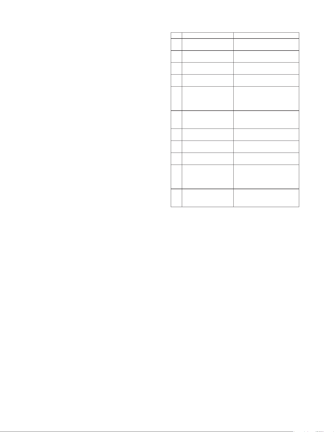
No. Items to be checked Possible malfunction
1
Has the unit been
installed correctly?
2
The unit may drop, shake or
emit noise.
Have you done the
refrigerant leakage test?
3
It may cause insufficient cooling
(heating) capacity.
Is heat insulation of
pipeline sufficient?
4
It may cause condensation and
water dripping.
Is water drained well?
5
It may cause condensation and
water dripping.
6
It may cause malfunction or
damage the parts.
Is the voltage of power
supply according to the
voltage marked on the
nameplate?
7
Is electric wiring and
pipeline installed
correctly?
It may cause malfunction or
damage the parts.
It may cause electric leakage.
Is the unit grounded
securely?
8
Does the power cord
follow the specification?
9
It may cause malfunction or
damage the parts.
Is there any obstruction
in air inlet and air outlet?
10
It may cause insufficient cooling
(heating).
11
It may cause malfunction or
damaging the parts.
Are the dust and
debris caused
during installation
removed?
The gas valve and liquid
valve of connection pipe
are open completely?
It may cause insufficient cooling
(heating) capacity.

15
16
Installation Manual
(Para unidad externa)
THE EXPERTS IN ROOM AIR CONDITIONING
m
z,
0
r
ESPAÑOL
17
ESPAÑOL

18
lnstrucciones de seguridad
/
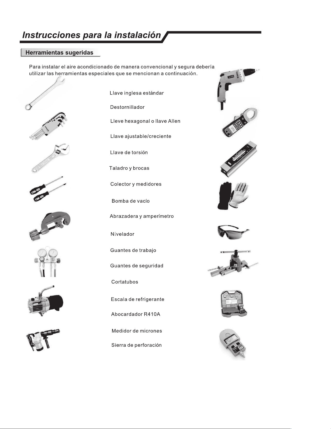
• 1. Para garantizar que la unidad funcione con normalidad, leer cuidadosamente el
manual antes de la instalaci6n y realizar la instalaci6n siguiendo este manual.
• 2. Al mover el aire acondicionado, no dejar que el aire ingrese al sistema de refrigeraci6n
o a la descarga del refrigerante.
• 3. Conectar el aire acondicionado a tierra de manera correcta.
• 4. Verificar cuidadosamente los cables y la tuberia. Asegurar de que esten correctos y
firmes antes de conectar la electricidad.
• 5. Debe haber un interru
tor de aire.
• 6. Luego de la instalac16n, el usuario debe operar el aire acondicionado de manera
correcta segun el manual. Tener un lugar de almacenamiento correcto para el
mantenimiento y traslado del aire acondicionado en el futuro.
• 7. El fusible de la unidad:
See
G
R
Á
F
I
CO E.1
• 8. Se debe incorporar en el cableado fijo un Dispositivo de Corriente Residual (RCD por
sus siglas en ingles) con un rango superior a 1 OmA seg(m las norm as nacionales.
• 9. Advertencia: Riesgo de descarga electrica: puede causar lesiones o la muerte.
Desconectar todos los suministros electricos remotos antes de realizar el servicio.
• 10. La mejor longitud de la tuberia de conexi6n entre la unidad interna y la externa es
menos que 7,5 metros (24,6 pies). Si la distancia es mayor que la longitud afectara la
eficiencia del aire acondicionado.
• 11. Este electrodomestico no esta destinado para ser utilizado por personas
(incluidos nios) con capacidades mentales, sensoriales y fisicas reducidas o falta
de experiencia y conocimiento, a menos que hayan sido supervisados o instruidos
sobre el uso def
electrodomestico por una persona responsable por su seguridad.
Se debe supervisar a los nios pequeos para asegurarse de que no jueguen con
el electrodomestico.
•
12. Este electrodomestico puede ser utilizado por menores de 8 anos en adelante y
por personas con capacidades fisicas, sensoriales o mentales reducidas o falta de
experiencia o conocimiento solo si han sido supervisados o instruidos sobre el uso
del electrodomestico en una forma segura y hayan entendido los peligros que incluye.
Los nios no deben jugar con el electrodomestico. La limpieza y el mantenimiento no
debe realizarse por los nines sin supervision.
• 13. Las pilas del control remote se deben reciclar o desechar de manera correcta.
Eliminaci6n de las pi las --- Desechar las pilas como desechos municipales en el
punto de recolecci6n.
ESPAÑOL
19
ESPAÑOL
20
ESPAÑOL
21
ESPAÑOL
22
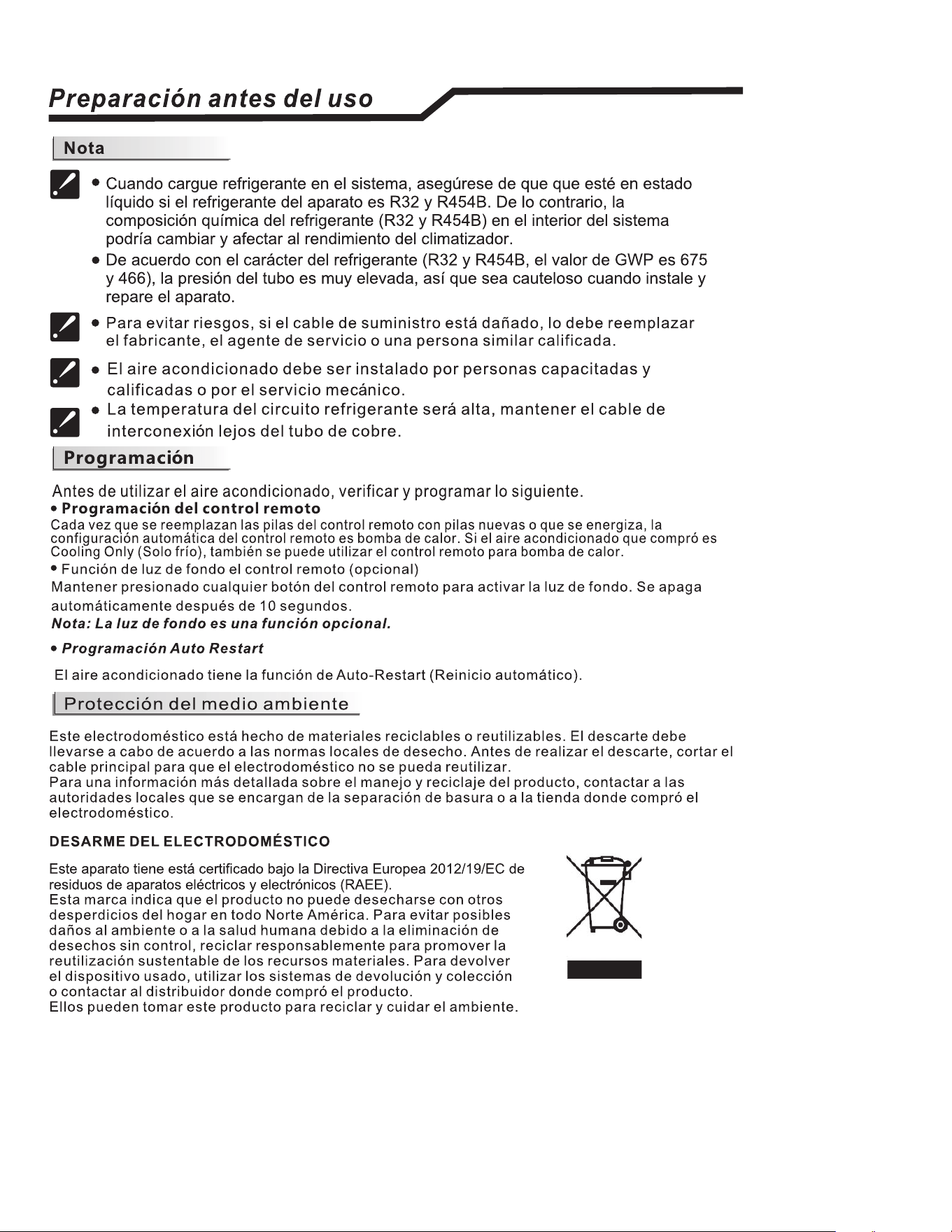
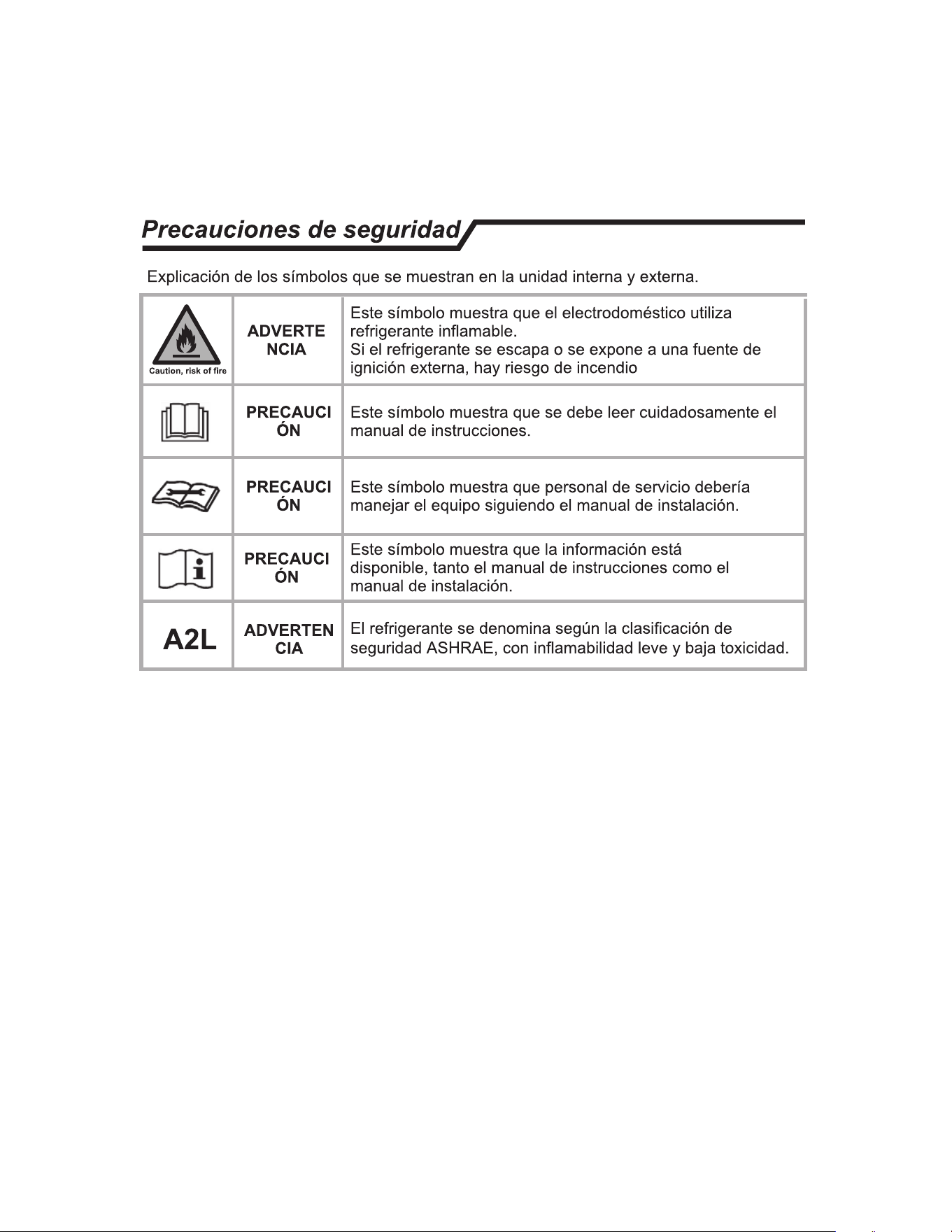
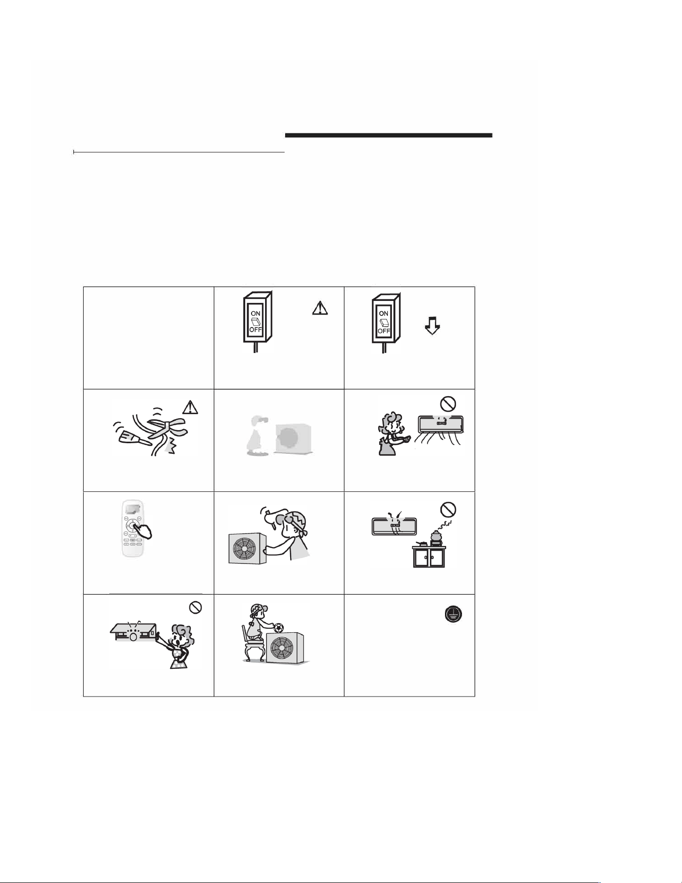
Precauciones de seguridad /
Los sfmbolos en este Manual de Uso y Cuidado se especifican a continuaci6n.
No hacerlo.
•
La conexi6n a tierra es esencial.
Prestar atenci6n a la situaci6n.
Advertencia: El manejo incorrecto
puede causar serios peligros como
la muerte, lesiones graves, etc.
Utilizar un suministro de energia
correcto segun el requisito de rango
de la placa. De lo contrario, pueden
ocurrir fall as graves, peligros o hasta
un incendio.
No unir, tirar o presionar el cable de suministro
de energia para que no se rompa el cable.
Puede ocurrir una descarga electrica o
incendios si se rompe el cable.
�
�
Apagar el electrodomestico con el control
remoto primero antes de cortar el
suministro de energia en caso de que
ocurra un mal funcionamiento.
No tocar los botones cuando sus
ma nos esten humedas.
Evitar que el disyuntor del circuito de suministro
de energia o el enchufe tenga polvo. Conectar
el cable de suministro de energia de manera
firme y correcta para que no haya descargas
electricas o incendios debido al mal contacto.
Nunca se debe colocar un palo o un
articulo similar en la unidad. Ya que el
ventilador rota a gran velocidad, esto
puede causar daos.
No debe reparr el electrodomestico
usted mismo. Si se hace de manera
incorrecta, Uede causar descargas
electricas, etc.
No colocar ningun objeto en la
unidad interna.
-5-
No utilizar un disyuntor del suministro de
energia o tirar del enchufe durante el
funcionamiento. Esto puede causar un
incendio debido a las chispas, etc.
El aire fresco en contacto con Ud. durante
un largo tiempo es perjudicial para su salud.
Se aconseja que el flujo de aire se desvie
por toda la habitaci6n.
Evitar que el flujo de aire este en
contacto con quemadores de gas y
hornos.
m
Es responsabilidad del usuario que el
electrodomestico este conectado a tierra
por un tecnico con licencia. segun los
c6digos locales u ordenanzas.
ESPAÑOL
23
ESPAÑOL
24
ESPAÑOL
25
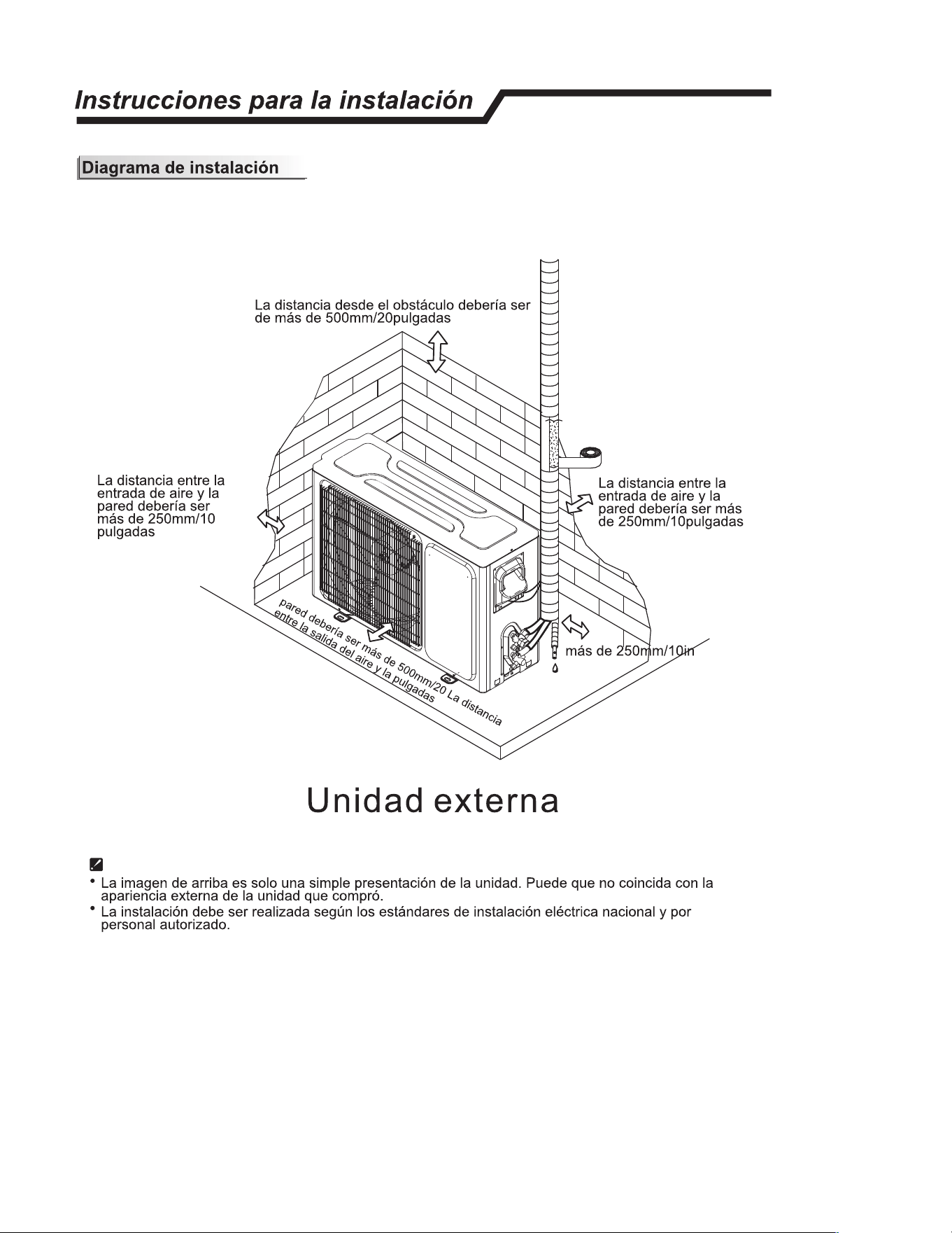
lnstrucciones para la instalaci6n /
lnstrucciones del sitio
Sitio para instalar la unidad externa
• Donde sea conveniente instalar y muy ventilado.
•
Evite instalar donde haya fugas de gas inflamable.
• Mantenga la distancia requerida desde la pared.
• Mantenga la unidad externa lejos de polvos, salidas de gas de
vulcanizaci6n.
• Evite instalar cerca de la calle donde hay riesgo de agua fangosa.
• Una base fija para que no incremente el ruido del funcionamiento.
•
Donde nada bloquee la salida de aire.
•
Evite instalarla bajo la luz directa del sol, en un pasillo o cerca de
fuentes de calor y ventiladores. Mantengala lejos de materiales
inflamables, niebla espesa de aceite y lugares humedos o
irregulares.
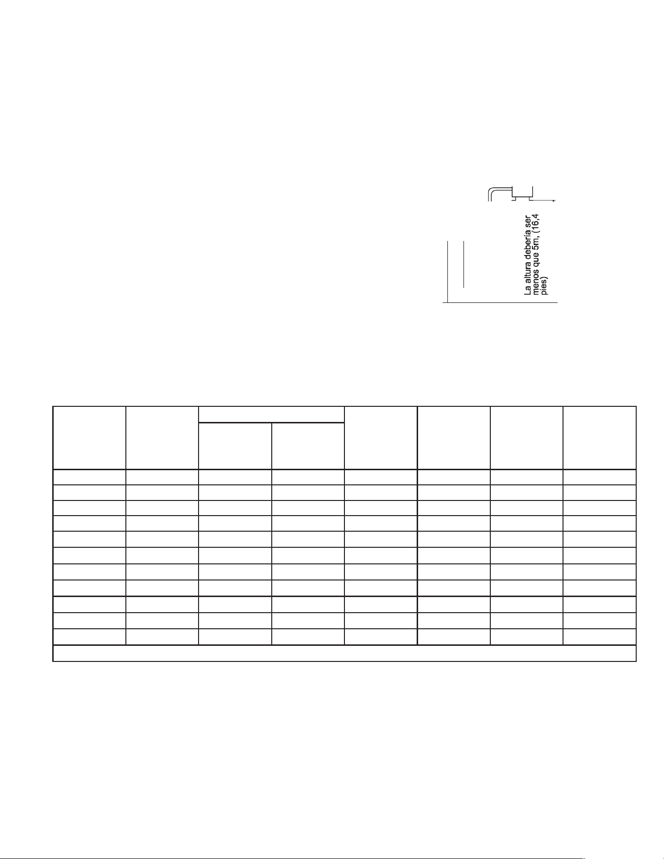
Unidad externa
La longitud de la tuberia
es 20 metros (65,4 pies)
Max.
Unidad interna
( La unidad exterior es m
á
s alta
q
ue la unidad interior )
• En caso de que la longitud de la tuberia sea mas que 7,5m (24,6pies), el refrigerante deberia ser
cargado adicionalmente seg(m la siguiente tabla.
Si la altura o la longitud de la tuberia esta fuera del alcance de la tabla, consultar al comerciante.
La instalaci6n de la unidad interna se refiere al manual de instalaci6n de la unidad externa.
-8-
ESPAÑOL
Capacidad
(Btu/h)
Precarga de
refrigerante
Tamaño de la tubería
Estándar
Largura
(ft)
Max.
Elevation
H (ft)
Máximo.
Elevación
L (ft)
Adicional
Refrigerante
(oz/ft)
LÍQUIDO GAS
FPHSR09A1C 33.5 oz 1/4" 3/8" 25 50 66 .22
FPHSR09A3D 35.2 oz 1/4" 3/8" 25 50 66 .22
FSHSR09B1C 21.2 oz 1/4" 3/8" 25 50 66 .22
FPHSR12A1C 35.3 oz 1/4" 3/8" 25 50 66 .22
FPHSR12A3D 38.1 oz 1/4" 3/8" 25 50 66 .22
FSHSR12B1C 21.9 oz 1/4" 3/8" 25 50 66 .22
FPHSR18A3D 53 oz 1/4" 1/2" 25 50 100 .22
FSHSR18B3D 45.9 oz 1/4" 1/2" 25 50 100 .22
FPHSR24A3D 70.6 3/8" 5/8" 25 50 100 .32
FSHSR24B3D 47.6 3/8" 5/8" 25 50 100 .32
FSHSR36B3D 70.6 3/8" 5/8" 25 50 100 .43
Table G.2
26
ESPAÑOL
27
ESPAÑOL
28
lnscciones para la instalaci6n /
I Energia y cableado
Conexi6n de/ cable
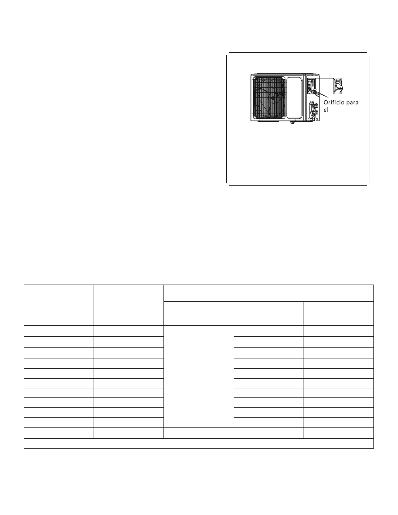
• Unidad externa
1) Quitar el tablero de la unidad desajustando el tornillo.
Conectar los cables a la terminal del tablero de manera
individual de la siguiente manera.
2) Asegurar el cable de alimentaci6n en el tablero de
control con una abrazadera.
3) Volver a instalar el tablero de la unidad a su posici6n
original con un tornillo.
4) Utilizar un disyuntor entre la fuente de alimentaci6n y la
unidad. Se debe proporcionar un dispositivo de desconexi6
n para desconectar todas las lfneas de suministro.
Precauci6n:
Chasis
Tablero de cableado
Unidad externa
Las imagenes de este manual estan basadas en la
vista externa de un modelo estandar. Por
consiguiente, la forma puede diferir un poco del aire
acondicionado que usted eligi6.
1. Nunca se debe dejar de tener un circuito de energia individual especifico para el aire acondicionado.
Para los metodos del cableado, ver el diagrama del circuito publicado dentro del acceso de la puerta.
2. Confirmar que el espesor del cable sea tan especifico coma en las especificaciones de la fuente
de energia.
3. Verificar los cables y asegurar que esten bien sujetos despues de la conexi6n.
4. lnstalar un disyuntor de fugas a tierra en areas humedas o mojadas.
Cable Speccaons
Atenci6n:
El enchufe debe estar accesible a(m despues de la instalaci6n del electrodomestico en caso de
necesitar desconectarlo. Si no es posible, conectar el electrodomestico a un interruptor bipolar
con una separacion de contacto de al menos 3mm colocado en una posicion accesible despues
de la instalacion.
ESPAÑOL
Modelo Diámetro del cable (AWG)
Cable de interconexión
entre la unidad interior y
exterior
Fuente de alimentación principal a la unidad exterior
Tamaño del cable MOP (Clasificación
de dispositivo de
sobrecorriente)
MCA (Ampacidad mínima
del circuito)
FPHSR09A1C 14-4 AWG 600V THHN Tamaño según códigos
eléctricos locales y
nacionales.
25A 16A
FPHSR09A3D 14-4 AWG 600V THHN 15A 9.5A
FSHSR09B1C 14-4 AWG 600V THHN 25A 14.6A
FPHSR12A1C 14-4 AWG 600V THHN 25A 16A
FPHSR12A3D 14-4 AWG 600V THHN 15A 10.5A
FSHSR12B1C 14-4 AWG 600V THHN 25A 15.4
FPHSR18A3D 14-4 AWG 600V THHN 30A 20A
FSHSR18B3D 14-4 AWG 600V THHN 20A 14.5A
FPHSR24A3D 14-4 AWG 600V THHN 35A 22A
FSHSR24B3D 14-4 AWG 600V THHN 35A 21A
FSHSR36B3D 14-4 AWG 600V THHN 40A 25.8A
Table E.1
Atencion:
El enchufe debe estar accesible a(m despues de la instalaci6n del electrodomestico en caso de necesitar desconectarlo. Si no es
posible, conectar el electrodomestico a un interruptor bipolar con una separacion de contacto de al menos 3mm colocado en una
posicion accesible despues de la instalacion.
29
ESPAÑOL
El diagrama es solo de referencia; se deben seguir los terminales reales del producto.
30
ESPAÑOL
31
Installation Manual
(Unite Exterieur)
►
z
•
►
FRANÇAIS
32
FRANÇAIS

33
Consignes de securite
/
• 1. Afin de garantir le fonctionnement correct de cet appareil, merci de lire attentivement cette
notice avant d'installer le climatiseur, en tenant de respecter les consignes qui y sont livrees.
• 2. Ne laissez l'air penetrer ni a l'interieur du systeme de refrigeration ni a l'interieur du systeme
d'evacuation du liquide frigorigene lorsque vous deplacez l'appareil.
• 3. Reliez correctement l'appareil a la terre.
• 4. Verifiez les cables et conduits de raccordement attentivement. Assurez-vous qu'ils sont en bon
etat et solides avant de proceder au branchement de l'appareil.
• 5. Un interrupteur pneumatique doit etre utilise.
• 6. Une fois !'installation terminee, l'operateur doit faire fonctionner le climatiseur
conformement aux consign es fournies dans cette notice, et la conserver afin de pouvoir
depanner/entretenir le climatiseur par la suite.
• 7. Fusible de cet appareil :
Ver tabla E.1
• 8.Un interrupteur a courant differentiel, dote d'une capacite minimum de 1 OmA, doit etre
integre aux cables fixes, conformement aux Reglementations Nationales en vigueur.
• 9. Mise en garde: risque d'electrocution, susceptible d'entrainer de graves blessures,
voire la mart. Debranchez toutes les sources d'alimentation electriques a distance avant
de proceder a la manipulation des dispositifs.
• 10. La meilleure longueur de raccordement entre l'unite interieure et l'unite exterieure se
situe endessous de 7,5 metres (24,6pieds). Si la distance recommandee n'etait pas
respectee, cela impacterait l'efficacite du climatiseur.
• 11. Cet appareil n
'
est pas conu pour etre utilise par des personnes (y compris les
enfants) ayant des capacites physiques, sensorielles ou mentales reduites, ou
manquant d
'
experience et de connaissances, a moins d
'
etre supervise ou instruit
par une personne responsable de leur securite. Les enfants doivent etre surveilles
pour s
'
assurer qu
'
ils ne jouent pas avec l
'
appareil.
• 12. Cet appareil peut etre utilise par des enfants ages de 8 ans et plus, ainsi que par des
personnes dont les capacites mentales, physiques et sensorielles sont diminuees, ou
manquant de !'experience/des connaissances necessaires pour le faire fonctionner, dans
la mesure ou elles sont placees sous la surveillance d'un tiers conscient des risques
impliques et des mesures a prendre en cas de danger. Les enfants ne doivent pas jouer
avec cet appareil. Le nettoyage et la maintenance de l'appareil ne doivent pas etre
effectues par des enfants sans surveillance.
•
13. Les piles de la telecommande doivent etre recyclees ou eliminees de faon correcte.
Elimination des piles --- Merci de vous debarrasser des piles au pres du point de collecte le
plus proche de chez vous, et non pas avec le reste de vos dechets domestiques.
-1-
FRANÇAIS
34
FRANÇAIS
35
FRANÇAIS
36
FRANÇAIS
37
FRANÇAIS
38
FRANÇAIS
39
FRANÇAIS
40
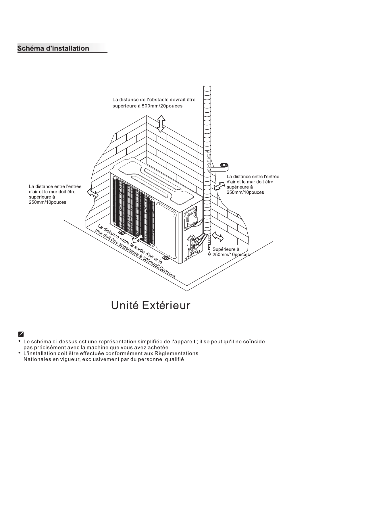
Consignes d'instation /
Consignes
relatives au site
Site destine a accueir /'unite exteeure
•
Partout ou l'appareil peut etre installs facilement et ou une bonne
ventilation existe.
•
E
vitez d'installer l'appareil ou ii existe un risque possible de gaz
inflammable.
• Respectez les distances recommandees entre l'appareil et les murs.
•
Maintenez l'unite exterieure
a l'ecart des melanges graisses/poussiere,
des sorties de gaz.
Unite eerieure
La longueur de la
conduite est de 20
metres max.
(65,4 pi eds).
•
E
vitez d'installer l'appareil
a proximite d'une route, afin d'eviter la
Unite interieure
presence de boue.
• lnstallez l'appareil sur une base fixe, afin d'eviter !'apparition de bruits.
•
Partout ou la sortie d'air n'est pas bloquee.
•
E
vitez d'exposer l'appareil aux rayons directs du soleil, dans un endroit
trop sombre, pres de la route, pres de sources de chaleur et de ventilation.
Maintenez-le egalement eloigne des substances inflammable, des huiles,
L'unite exterieure est plus haute
et des endroits humides et peu securises.
que l'unite interieure
• Dans le cas ou la longueur de la conduite depasserait 7,5m (24,6 pieds},
le liquide frigorigene doit etre reapprovisionne, comme le montre !'Illustration suivante.
Si la longueur de la conduite ou la hauteur ne correspondent pas aux valeurs mentionnees
dans la Table, veuillez contacter le fabricant.
Pour le montage de l'unite interieure, faites reference au manuel de montage de
l
'unite interieure.
-8-
FRANÇAIS
Capacité
(Btu/h)
Pré-charge du
réfrigérant
Pipe Size
Norme
Longueur (ft)
Max.
ÉlévationH (ft)
Longueur
maximale
L (ft)
Autres
Réfrigérant
(oz/ft)
LIQUIDE
GAZ
FPHSR09A1C 33.5 oz 1/4" 3/8" 25 50 66 .22
FPHSR09A3D 35.2 oz 1/4" 3/8" 25 50 66 .22
FSHSR09B1C 21.2 oz 1/4" 3/8" 25 50 66 .22
FPHSR12A1C 35.3 oz 1/4" 3/8" 25 50 66 .22
FPHSR12A3D 38.1 oz 1/4" 3/8" 25 50 66 .22
FSHSR12B1C 21.9 oz 1/4" 3/8" 25 50 66 .22
FPHSR18A3D 53 oz 1/4" 1/2" 25 50 100 .22
FSHSR18B3D 45.9 oz 1/4" 1/2" 25 50 100 .22
FPHSR24A3D 70.6 3/8" 5/8" 25 50 100 .32
FSHSR24B3D 47.6 3/8" 5/8" 25 50 100 .32
FSHSR36B3D 70.6 3/8" 5/8" 25 50 100 .43
Table G.2
41
FRANÇAIS
42
FRANÇAIS
43
Consignes d'instation /
l
Alimentation et cablage
Raccordement du cable
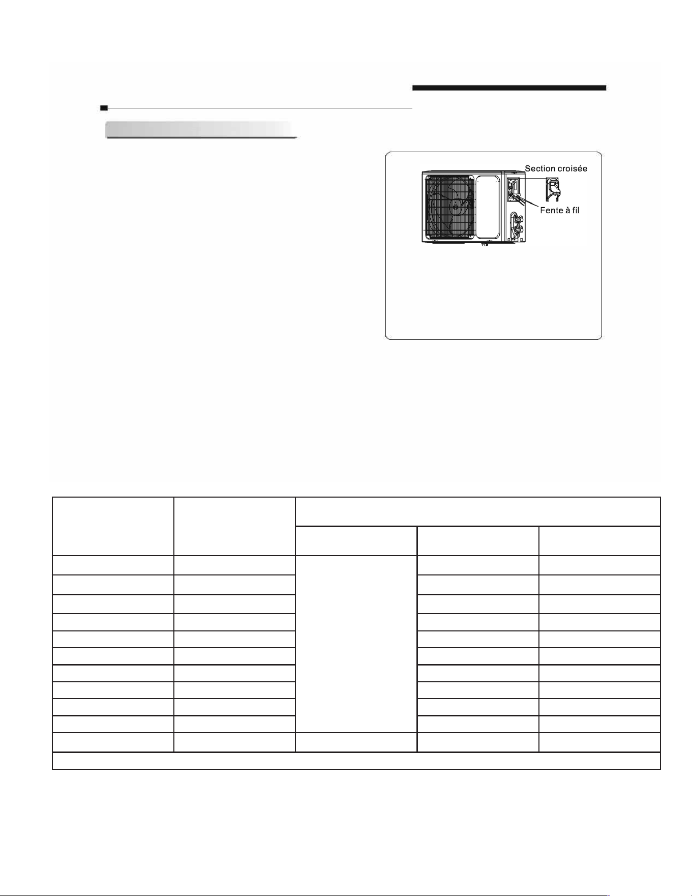
• Unite exterieure
1 )Retirez la section de cable de l'unite en desserrant les
vis. Connectez les cables aux bornes individuellement au
panneau de controle, de la fa9on suivante.
2)Securisez le cordon d'alimentation sur le panneau de
controle au moyen d'une pince.
3)Reinstallez la section de cable dans sa position d'origine,
au moyen d'une vis.
4) lnstallez un disjoncteur adapte au entre la source
d'alimentation et l'unite. Un systeme de deconnexion
raccorde au reseau doit etre installe.
Attention:
Unite exterieure
Les schemas de cette notice se basent sur une vue
exterieure du modele de base. II se peut done que la
forme de votre climatiseur varie de ceux representes.
1. N'oubliez jamais d'installer un circuit electrique individuel specifiquement relie au climatiseur.
En ce qui concerne la methode de cablage, consultez le diagramme present a l'interieur de la porte d'acces.
2. Verifiez que l'epaisseur des cables est conforme a celle mentionnee sur plaque nominative
3. Verifiez que les cables sont bien relies et qu'ils sont correctement serres.
4. Pensez bien a installer un disjoncteur relie au sol dans les endroits humides ou mouilles.
Cacteques du cable
Capacite(Btuh)
Cordon d'alimentation
Cordon d'alimentation
MO
P pe
Zones transversales
MCA
standard
9K(208/230V)
15A
9.5A
SJTW
4X14G
12K(208/230V)
15A 10.5A SJTW 4X14G
18K(208/230V)
30A
20A
SJTW
4X14G
24K(208/230V)
35A 22A SJTW 4X14G
Attention:
La prise doit etre accessible meme une fois !'installation de l'appareil achevee, dans le cas ou ii
serait necessaire de le debrancher. Si cela n'est pas possible, reliez l'appareil
a un commutateur
muni d'une separation de contact d'au moins 3 mm, situe dans un endroit accessible meme apres
installation.
-11-
FRANÇAIS
Modèle Diamètre du fil (AWG)
Fil d’interconnexion
entre l’unité intérieure et
extérieure
Alimentation principale vers l’unité extérieure
Taille de fil MOP (évaluation du
dispositif de surintensité)
MCA (intensité minimale
du circuit)
FPHSR09A1C 14-4 AWG 600V THHN Taille selon les codes
électriques locaux et
nationaux.
25A 16A
FPHSR09A3D 14-4 AWG 600V THHN 15A 9.5A
FSHSR09B1C 14-4 AWG 600V THHN 25A 14.6A
FPHSR12A1C 14-4 AWG 600V THHN 25A 16A
FPHSR12A3D 14-4 AWG 600V THHN 15A 10.5A
FSHSR12B1C 14-4 AWG 600V THHN 25A 15.4
FPHSR18A3D 14-4 AWG 600V THHN 30A 20A
FSHSR18B3D 14-4 AWG 600V THHN 20A 14.5A
FPHSR24A3D 14-4 AWG 600V THHN 35A 22A
FSHSR24B3D 14-4 AWG 600V THHN 35A 21A
FSHSR36B3D 14-4 AWG 600V THHN 40A 25.8A
Table E.1
Attention:
La prise doit etre accessible meme une fois !’installation de l’appareil achevee, dans le cas ou ii serait necessaire de le
debrancher. Si cela n’est pas possible, reliez l’appareil a un commutateur muni d’une separation de contact d’au moins 3 mm,
situe dans un endroit accessible meme apres installation.
44
FRANÇAIS
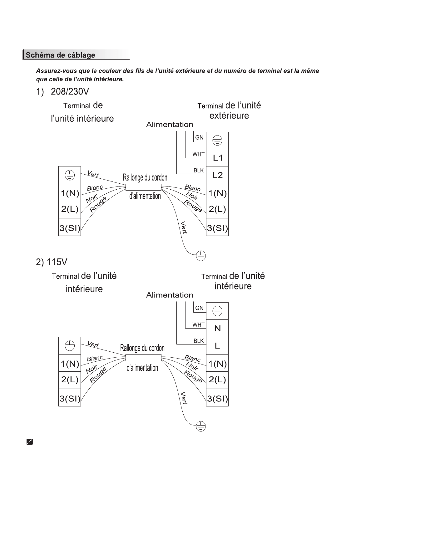
Le diagramme est uniquement une référence, les bornes réelles du produit doivent être suivies.
45
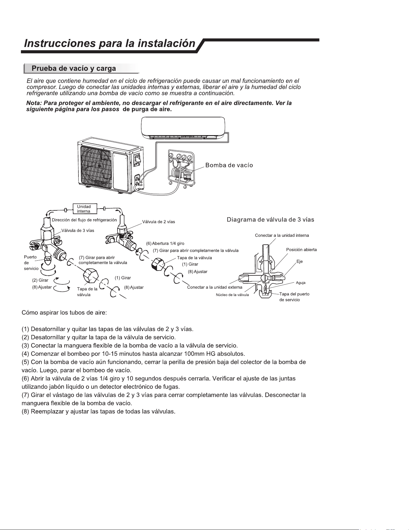
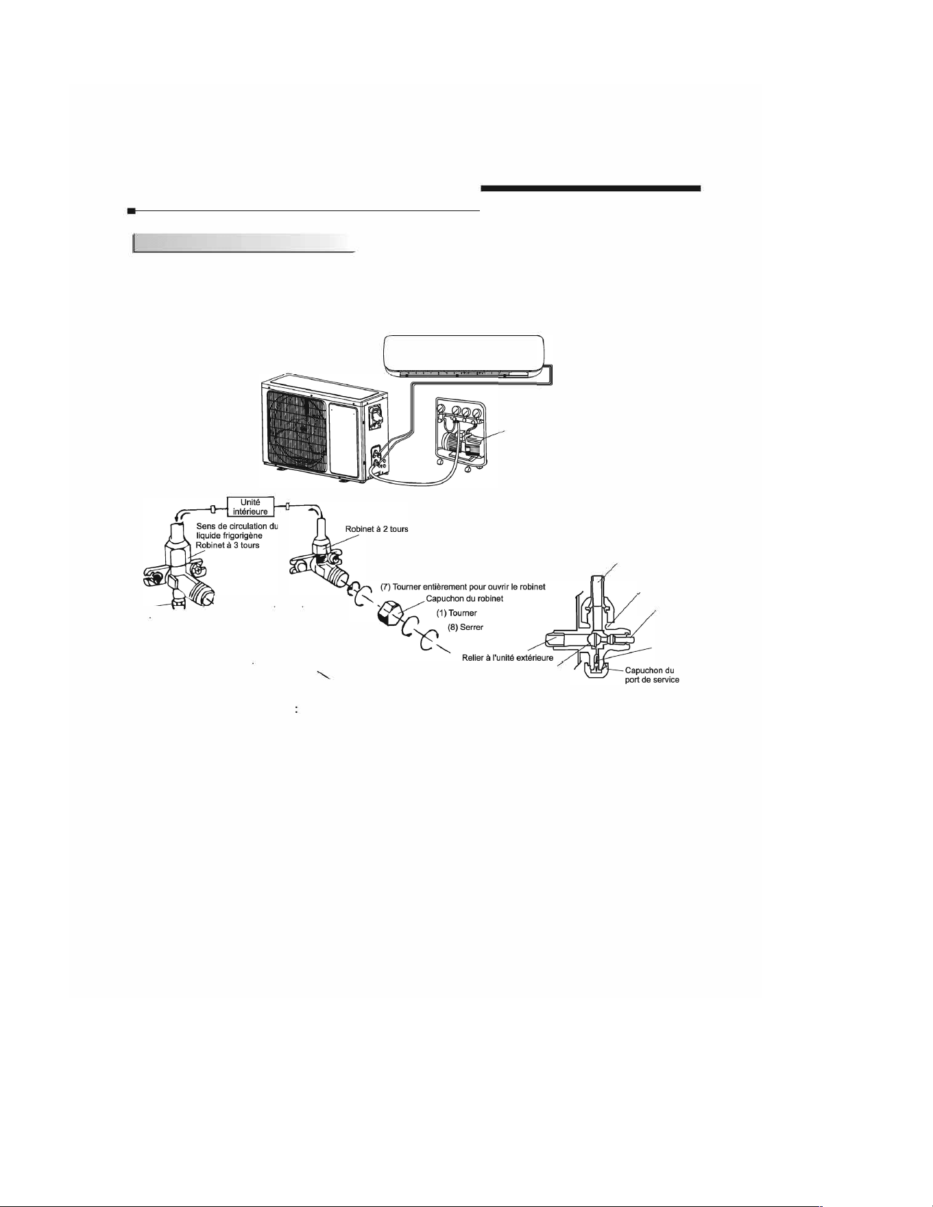
Consignes d'instation /
Charge et decharge
Le circuit est charge en humidite et en eau, ce qui peut entrainer un dysfonctionnement du compresseur.
Apres avoir connecte les unites interieures et exterieures, liberez l'air et l'humidite contenus dans le circuit
de refrigeration au moyen d'une pompe a vide, comme cela est represente ci-dessous.
Remarque : pour proteger l'environnement, pensez a ne pas decharger le liquide refrigerant directement dans l'air qui vous entoure.
Pour connaitre les possibilites qui s'orent a vous, consultez la page suivante.
Pompe a vide
Diagramme du robinet a 3 tours
(7) Tourner entierement
Port de
f
,
,
pour ouvnr le rob,net
seice �
�
(2)T
o
�
(1)T
oumer
(8) Serrer
Capuchon
' (8) Serrer
du robonet
Comment vider les tubes a air
(6) Ouvert sur 1/4 tour
( 1) Devissez et retirez les capuchons des robinets a 2 et 3 tours.
(2) Devissez et retirez le capuchon du robinet de service.
Partie centrale du robinet
(3) Branchez le flexible du dispositif d'evacuation au robinet de service.
Paie centrale du robinet
Position ouvee
Mandrin
Aiguille
(4) Demarrez la pompe a vide et faites-la tourner pendant 10-15 minutes jusqu'a ce que !'aspiration
atteigne 10 mm Hg absolus.
(5) Avec la pompe toujours en fonctionnement, fermez le bouton de pression basse situe sur le levier de
la pompe. Arretez ensuite la pompe.
(6) Ouvrez le robinet a 2 tours, puis refermez-le apres 10 secondes. Verifiez l'epaisseur de tous les joints
au moyen de savon liquide ou d'un detecteur de fuites electronique.
(7) Refermez bien les robinets a 2 et 3 tours. Debranchez le flexible de la pompe.
(8) Remettez les capuchons des robinets en place et serrez-les bien.
-13-
FRANÇAIS