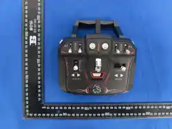
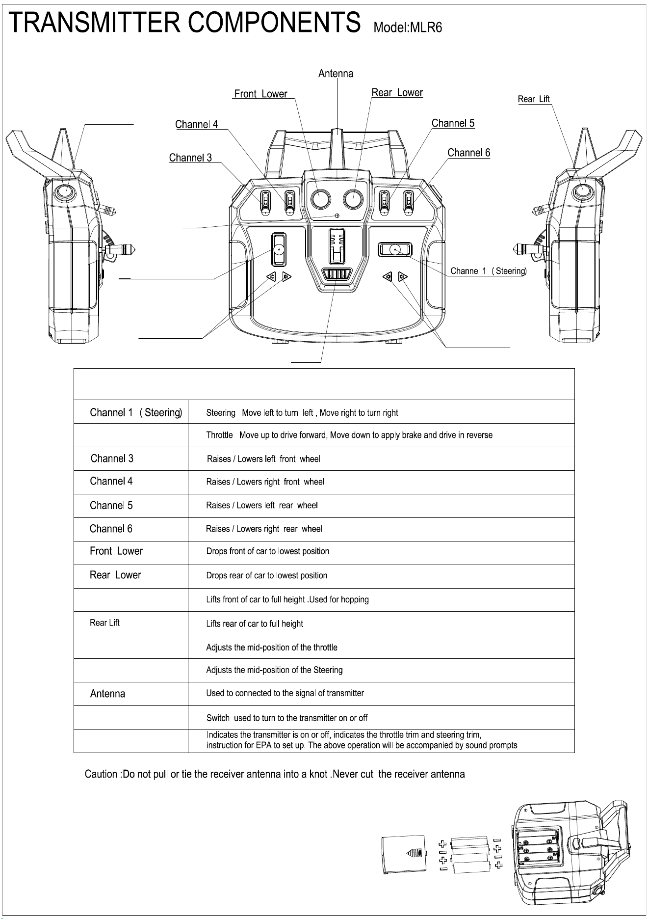
Front Lift
LED
ON/OFF
Steering Trim
Throttle Trim
Channel 2 (Throttle)
MLR6 Functions
LED
Throttle Trim
ON/OFF
Steering Trim
Front Lift
Channel 2 (Throttle)
INSTALLING THE TRANSMITTER BATTERIES
This transmitter requires 4 AA batteries.
1.Open the battery cover from the transmitter.
2.Install the batteries as shown.
3.Close the battery cover.
ESC SPECIFICATIONS
Model: MLR6-RX
Operating environment: 2.4GHz Redcat Protocol
Dimensions (LxWxH): 31.8mm x 26mm x 18.7mm)
Antenna Length: 60mm
Channels: 6
Weight: 21.6 grams
Band: 2.4GHz
Voltage Range: 6– 8.4V
Bind Type: Bind Plug
10A-2in1 BINDING:
1.Insert the bind plug into the channel 1 of ESC.
2.Power on the ESC, the LED will flash rapidly to indicate it is in bind mode
3.Push the the steering lever to right endpoint and hold up, then power on the transmitter; the LED on the
transmitter will flashing, the LED on the ESC stops flashing and lights will . indicate that the binding
procedure is completed.
Do not kink, cut or damage the antenna wire. The antenna is made of a coaxial wire; if the outer sheath
becomes damaged, the ESC will not work properly. If the antenna is damaged in any way, replace the antenna
before attempting to use the ESC.
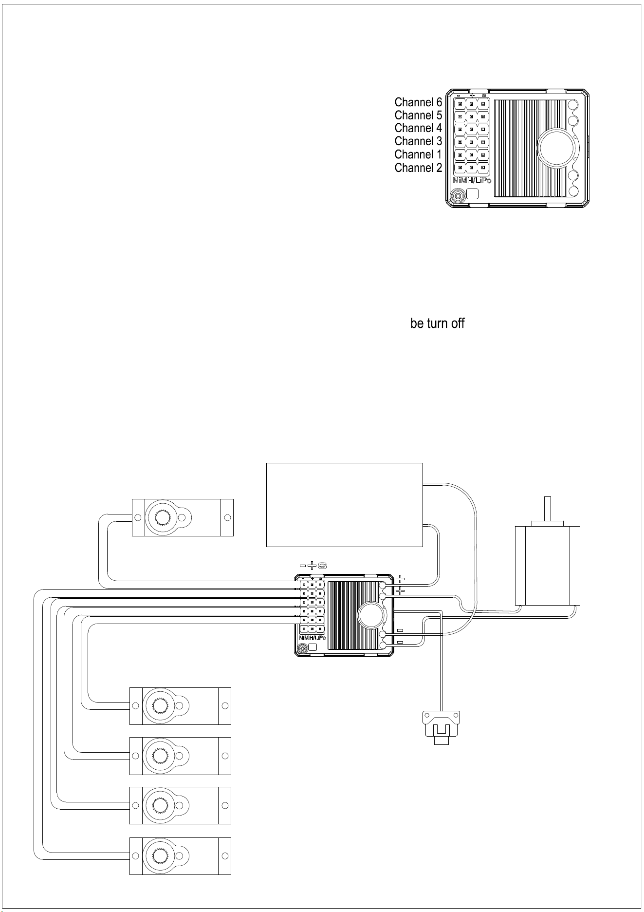
ESC ANTENNA
ESC
BATTERY
Installation when a motor controller is used
MOTOR
SERVO
Channel 1
SERVO
Channel 3
SERVO
Channel 4
SERVO
Channel 5
SERVO
Channel 6
SWITCH
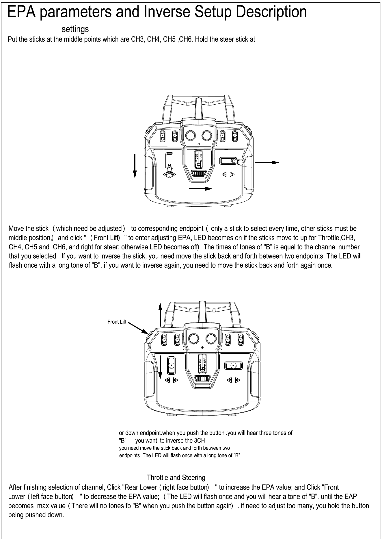
Enter the EPA
the right endpoint and the throttle stick at the CCW endpoint, Power on the radio.
the LED will flash quickly. indicate EPA Setup status
Release the steer stick and throttle stick. At this time, you can select the channel which need to adjusted .
EPA of selecting the channels and inverse
EPA regulation of 3CH 4CH 5CH 6CH
3CH 4CH 5CH and 6CH are in the middle position
3CH 4CH 5CH 6CH throttle and steering all can be adjusted
For example when you choose to enter the CH3 you push the stick at up
.if
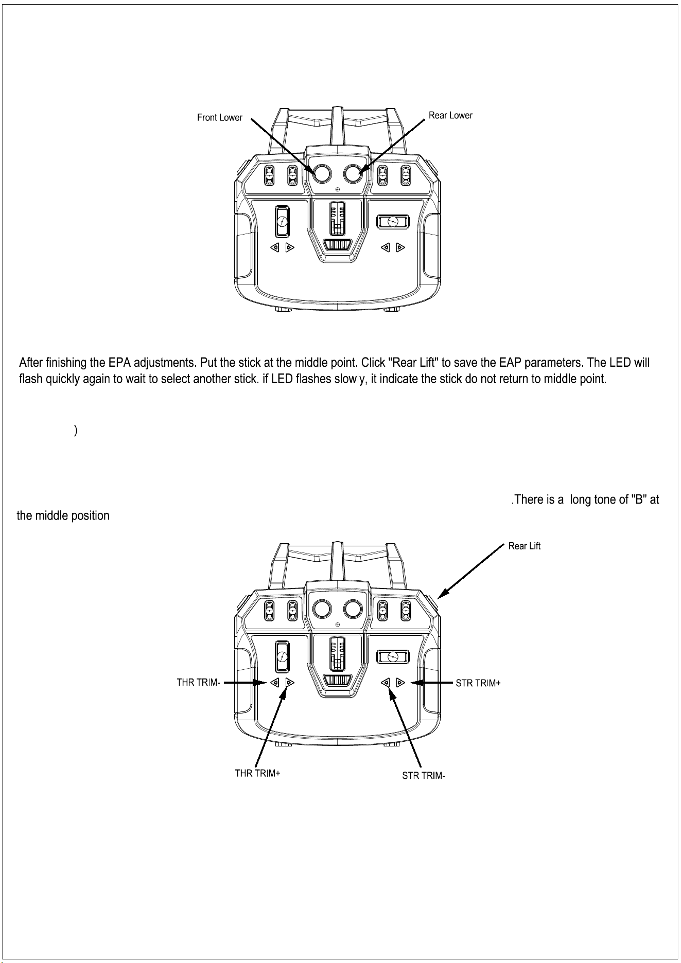
EPA of Saving and trimming
If you want to adjust EPA of other sticks, you operate as steps of 4-6.Exit the procedure of EPA setup by simultaneously
push down the "THR TRIM+" and "STR TRIM-". Then the LED becomes on to start up normally(The LED will flash once with a
tone of "B" .
Factory Reset Operation
Factory Reset Operation: Hold the throttle stick at brake endpoint , steer stick at left end
point and push down"Rear Lift" simultaneously, power on transmitter, The LED flashes four times slowly. when the LED
becomes on.you will hear a tone of "B" .the operation is successful.
When you make the mid-position adjustments to the throttle and steering .you need to push the THR TRIM- .THR TRIM+. STR
TRIM- and STR TRIM+.(Each time you push the button ,The LED will flash once with a tone of "B")
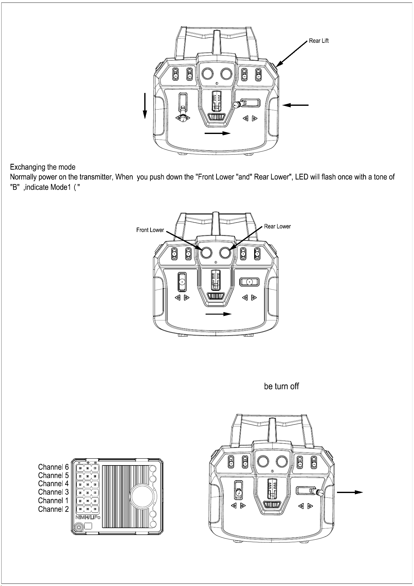
Front Lower" and " Rear Lower" as same as old version ); If the LED flash two times with two tones of
"B" , indicate Mode2("Raise right" and "Raise Left"for new version).Operation of alternating mode
10A-2in1 BINDING:
1.Insert the bind plug into the channel 1 of ESC.
2.Power on the ESC, the LED will flash rapidly to indicate it is in bind mode
3.Push the the steering lever to right endpoint and hold up, then power on the transmitter; the LED on the
transmitter will flashing, the LED on the ESC stops flashing and lights will . indicate that the binding
procedure is completed.

Federal Communications Commission (FCC) Statement.
This device complies with part 15 of the FCC Rules. Operation is subject to the following two
conditions:
(1) This device may not cause harmful interference, and
(2) this device must accept any interference received, including interference that may cause
undesired operation.
Note: This equipment has been tested and found to comply with the limits for a Class B digital
device, pursuant to part 15 of the FCC Rules. These limits are designed to provide Reasonable
protection against harmful interference in a residential installation. This equipment generates,
uses and can radiate radio frequency energy and, if not installed and used in accordance with the
instructions, may cause harmful interference to radio communications. However, there is no
guarantee that interference will not occur in a particular installation. If this equipment does
cause harmful interference to radio or television reception, which can be determined by turning
the equipment off and on, the user is encouraged to try to correct the interference by one or
more of the following measures:
•Reorient or relocate the receiving antenna.
•Increase the separation between the equipment and receiver.
•Connect the equipment into an outlet on a circuit different from that to which the receiver is
connected.
•Consult the dealer or an experienced radio/TV technician for help.
Warning: Changes or modifications not expressly approved by the party responsible for
compliance could void the user's authority to operate the equipment.
Note: The manufacturer is not responsible for any radio or TV interference caused by
unauthorized modifications to this equipment. Such modifications could void the user’s authority
to operate the equipment.
RF exposure statement:
RF Exposure Information SAR compliance is based on a separation distance of 0 mm between the unit and
the body of the user.The use of holsters and similar accessories should not contain metallic components
in its assembly, the use of accessories that do not satisfy these requirements may not comply with FCC
RF exposure requirements, and should be avoided.