

TABLE OF CONTENTS
Box Contents & System Congurations .............................................................................3
Installation Steps ............................................................................................................. 4-13
Troubleshooting Guide ..................................................................................................... 14
Maintenance ....................................................................................................................... 15
Filter Replacements ...................................................................................................... 16-21
Performance & Certications ........................................................................................... 22
Warranty ............................................................................................................................. 23
Water for Life
®
Program .................................................................................................... 24
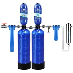
Meet clean, healthy water. Your new Aquasana
®
whole house Rhino
®
system was expertly engineered to reduce chemicals, bacteria, viruses,
and other contaminants commonly found in well water.
Enjoy the peace of mind that comes from knowing our award-winning
water lter technology is working for you.
WH-WELL WATER WITH UV
Next >
14
14
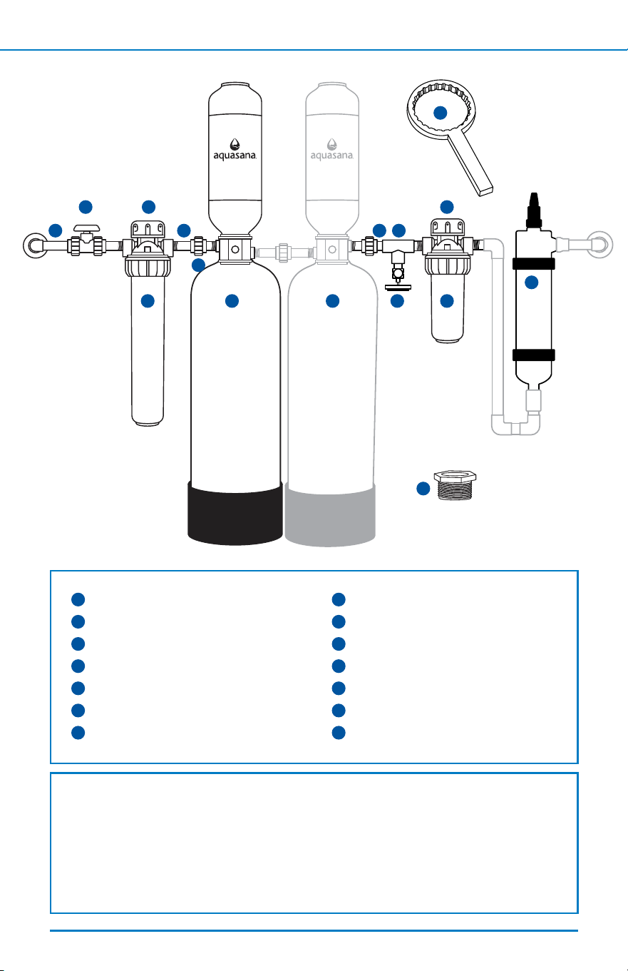
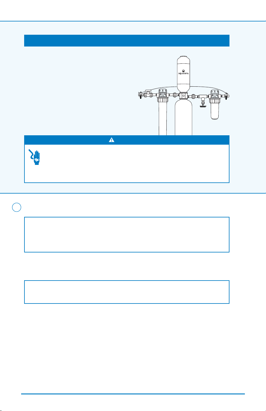
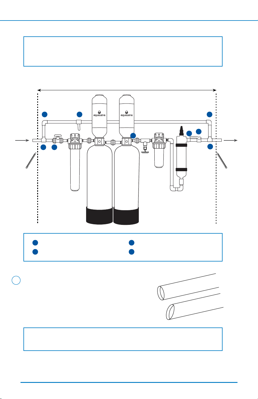
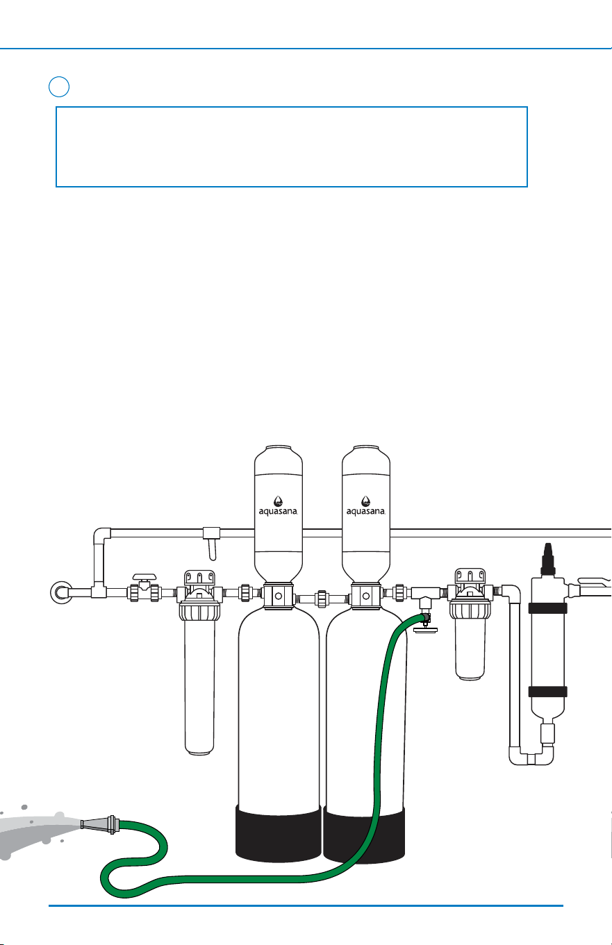
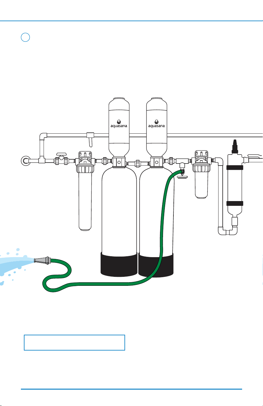
BOX CONTENTS & SYSTEM CONFIGURATION
3
< Back To Table of Contents Next >
1
Rhino
®
Well Water Tank
2
20" Pre-Filter
3
10" Post-Filter
4
Plastic Wrench
5
Fliter Support Brackets (2)
6
1" -
3
/
4
" Reducer Bushings (2)
7
Shut-O Valve
8
Slip Unions (2)
9
2.5" TOE Nipples (5)
10
3" Smooth Nipple
11
Brass Drain Valve
12
PVC Tee
13
Tall Salt-Free Water Conditioner (Optional)
14
UV Filter
7
3
8
1 13
6
6
4
10
5
112
9
5
12
Box contents will be packaged in multiple boxes.
Before beginning installation, please ensure all parts listed are present. If any part is
missing or damaged, do not attempt to install the system.
Please contact Customer Support for replacement parts at 866-662-6885.
Appearance of parts/components may vary depending on the time of purchase.

2
INSTALLATION STEPS
4
< Back To Table of Contents Next >
Tools recommended for installation: Optional components:
>> Click here to view the Rhino
®
Whole House installation video.
Precautions
• For all installations: Due to the varieties of home design, not all
congurations can be addressed in this guide. Anticipate the need for
additional parts and pieces including but not limited to pex tubing, clamps,
and mounting screws to install unit properly (available at a local home
improvement store or through your plumbing contractor).
• This system requires installation of a UV system.The minimum space is 20"
(above and below) to be able to service the UV system.
• DO NOT install this lter where the line pressure may exceed 100 psi. The
operating pressure range for this lter is between 20psi – 100psi. In areas
with high pressure (e.g. above 60 psi), a pressure reducing valve or pressure
regulator is recommended to be installed prior to the system.
• To safeguard your system from water hammer events we recommend the
installation of a water hammer arrestor at the beginning and end of the
system. The water hammer arrestor will help with instantaneous spikes in
pressure due to water hammer events typically caused by washing machines
and dishwashers. A water hammer event can happen regardless of water
pressure and any household can be subject to a water hammer event.
• Install on cold water lines only (40° – 90°F).
• Installation of the ltration system must comply with existing state and local
plumbing codes.
• Some local codes may require the use of a licensed plumber or certied
installer when disrupting a potable water line.
• It is recommended your system be installed indoors and out of direct
sunlight. Prolonged exposure to light can weaken plastic components, resulting
in lter housing failure. If this is not possible and the system is outdoors or
• Drill
• Wrench
• Channel locks
• Pressure reducing valve or pressure regulator
• Water hammer arrestor
• Pipe cutter
• NSF certied PVC primer and glue
• NSF certied plumber's tape
• Garden hose
• 5 gallon bucket
• Check valve
• Pro-Grade Bypass Kit
• Copper wire & grounding clamps
(if copper pipes are present)
• Pex tubing, crimp rings and cutter

2
INSTALLATION STEPS
5
< Back To Table of Contents Next >
in a sunny area, the unit must be protected from both direct sunlight and
freezing temperatures.
• Unit must be installed in an area where the main water line enters your home,
before connecting to the water heater. DO NOT install after a water heater or
on the hot water line.
• DO NOT install the tank on its side. It must be installed upright to maximize
contact with media bed.
• Pick an appropriate installation location where if the tank or any connection
thereto should leak, the resulting ow of water will not cause damage to
the surrounding area. Dimensions of systems vary—always allow an estimated
minimum of 60" clearance for height of tank, and a minimum of 44" for
oor space.
• Filtration tank must be ushed before running water from system into house.
• NSF certied plumber's tape (thread sealing tape) is the only sealer that
can be used on threaded ttings. DO NOT use pipe dope or PVC primer/glue
on threaded ttings. Exposure to these compounds will damage nipples
causing leaks.
• Properly tighten all ttings to ensure a leak-free assembly.
• If installing on metallic plumbing, two grounding clamps and #4 copper wire
are essential for safety.
• It is strongly recommended to install a check valve at the end of your system
conguration and before the water heater to protect your ltration system
from back ow.
2
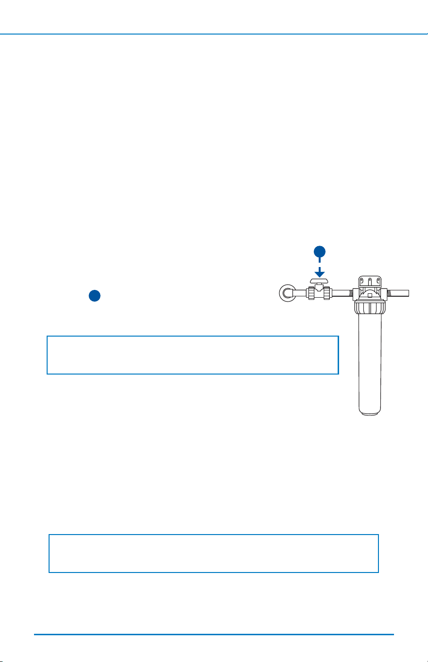
Select Location
Lay out system in appropriate conguration. Improper sequencing
of equipment will aect performance, and could possibly
damage your system.
1. Pick an appropriate installation location. Unit must be installed in an area
where the main water line enters your home, and before it connects to the
water heater. It is recommended to install after any outdoor hose bibs or
irrigation lines to avoid using ltered water where not needed.
2. Choose the location for a shut-o valve to be able to isolate your system.
If installing a check valve, it should be installed after your system but
before the water heater. If installing the Pro-Grade Bypass Kit, choose the
location at this time.
1
DO NOT install after the water heater or on the hot water line.
2
INSTALLATION STEPS
6
< Back To Table of Contents Next >
Pro-Grade Bypass Kit Installation:
IF YOUR SYSTEM does not include the Pro-Grade Bypass Kit, continue to step 2.
1. Once you’ve selected an appropriate location for your whole home
water lter system and main shut-o valve, lay out the bypass loop
and ensure you have all the components and tools required.
• The Pro-Grade Bypass Kit is specic to 1” PEX connections for easy
installation.
• Reference the system conguration image on page 9 when laying out
bypass loop components to ensure correct order and location.
2. Pre-assemble all the parts before starting the installation. Straighten
out your PEX tubing and plan for additional length that can be trimmed
down before the nal installation.
3. Mark your incoming water line where you would like to start your
bypass loop. This should be before your main PVC shut-o valve.
Prepare your existing pipes by cleaning the sections you plan to cut.
4. Once your bypass loop is prepared, continue to step 2 on next page
before making the nal connections.
5. Once the main system has been fully installed, cut down any PEX
tubing to ensure you have the proper length and complete bypass
loop connections.
6. Turn on main water line and check for leaks.
NOTE: Due to the variety of home design and spaces, anticipate the need
for additional items to install bypass loop properly. Additional items would
be available at a local home improvement store or through your plumbing
contractor. Not all congurations can be addressed in this guide.
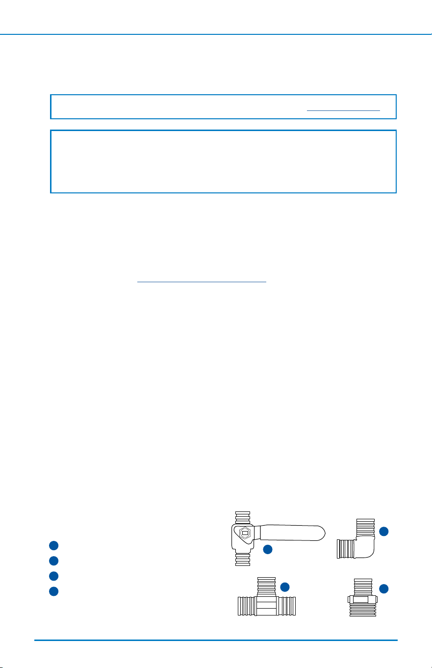
Bypass Kit Box Contents:
1
PEX 1” brass shut-o valves (2)
2
PEX 1” brass 90° elbows (2)
3
PEX 1” brass tees (2)
4
PEX 1” brass male adapters (2)
1
3
2
4
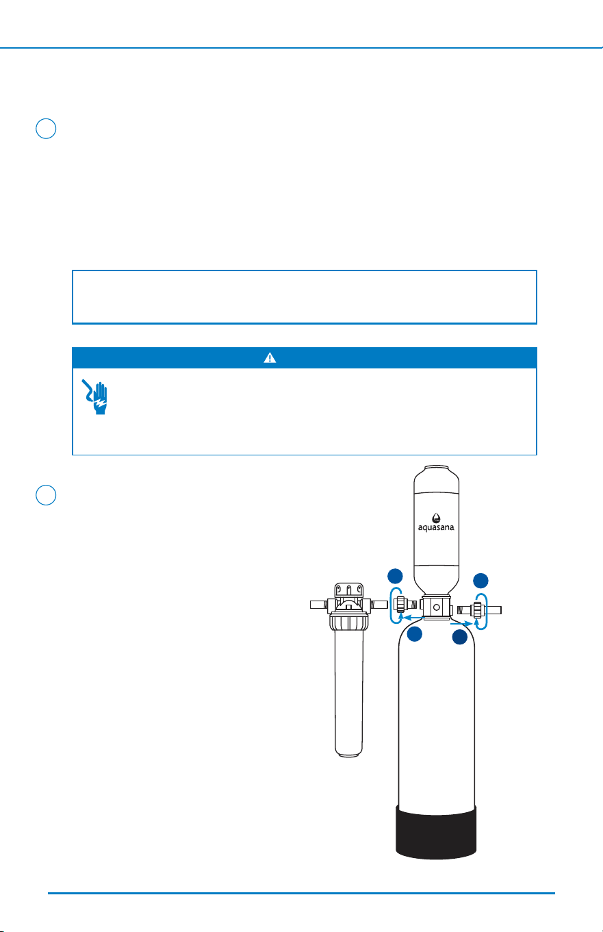
Prepare Rhino
®
Tank
1. Ensure the Rhino tank sits level. If it looks o-center or unlevel, reference
the troubleshooting section.
2. Pre-assemble all parts and dry-t the entire system to ensure proper
spacing and to conrm you have the necessary components for
installation. Reference system conguration image on page 3 to
understand the system layout and connections.
3. Connect all smooth tting connections using NSF certied primer and
glue. Smooth connections will be on the nipples, unions,shut-o valve,
and PVC tee. Once glue is applied, press and hold the connection tight
for 10-15 seconds.
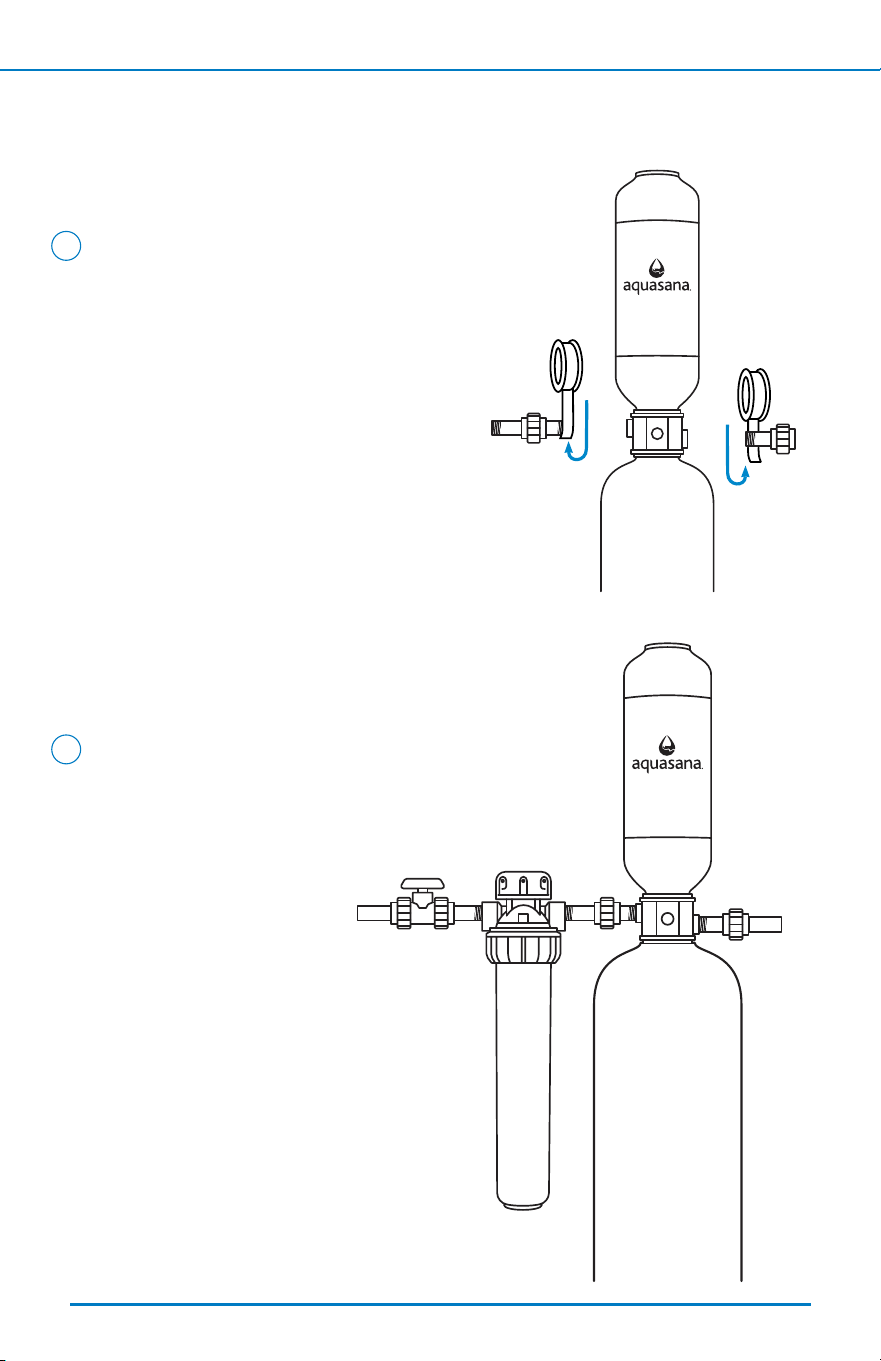
4. Carefully remove shipping caps from inlet
and outlet ports without damaging valve threads.
5. Wrap threaded nipple ends 3 times with NSF certied
plumber's tape. Insert the nipples and attached
unions to the ltration tank's threaded inlet
and outlet. Hand tighten and then tighten
again with a pipe wrench (2-2.5 rotations)
to seal the connections.
3
NOTE: DO NOT OVER-TIGHTEN. If space
does not allow for a pipe wrench to grip
the nipples, clamp to the glued union to
make nal rotations.
2
INSTALLATION STEPS
7
< Back To Table of Contents Next >
2
UV System Preparation
This set up requires the installation of a UV system. Before continuing,
stop now and read the separate, included UV manual in its entirety.
2
WARNING
Never look directly at a lighted UV lamp. Ultraviolet rays can be harmful to eyes.
Assembly is required before installation. Internal components are fragile.
>> Click here to view the UV Filter Owner's Manual.
2
INSTALLATION STEPS
8
< Back To Table of Contents Next >
2
Install Shut-o Valve and Ensure Spacing
1. Turn o the main water source. Drain water from lines to relieve
pressure by turning on a faucet at the lowest elevation inside your home.
2. Using a pipe cutter, cut into the main water supply line and catch any
remaining water in the 5-gallon bucket. Each system includes a 1" PVC
shut-o valve with the option of threaded or smooth connections,
as well as reducer bushings to connect to a
3
/
4
" main water line.
3. Loosely t shut-o valve to calculate the proper spacing of components.
4. Measure distance for Pre- and Post-Filter, Rhino
®
tank, and optional
add-ons (Salt-Free Water Conditioner) and mark pipe accordingly.
4
NOTE: You may need additional components to connect your system to the
main water line where it enters and exits the ltration system. Ensure you
have all components needed before proceeding to the next steps.
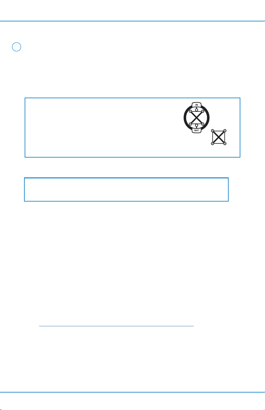
When installing on metallic
plumbing, ensure you take the
following precautions. Securely
install two (2) grounding clamps
and a #4 copper wire (not
included) across the location
where the system will be installed.
Tightly clamp at both ends, as
shown in the illustration.
Ground
Clamp
Ground
Clamp
Ground
Wire
COPPER PIPES ONLY (proceed to Step 4 for all other pipes)
NOTE: Installation could take 1–4 hours to complete. Plan accordingly as you
will be without water throughout the home during this time.
ELECTRICAL SHOCK HAZARD
Prior to installation on metallic plumbing, securely install two grounding clamps and
a #4 copper wire per installation instructions. Failure to follow these instructions can
result in death or electric shock.
WARNING
4
2
INSTALLATION STEPS
9
< Back To Table of Contents Next >
2
Cut Pipes
Cut pipe along the marked sections from
step 4 and clean ends of pipe. Ensure there
are no burrs, sharp edges, or deep scratches.
5
NOTE: Cut tubing as straight as possible with a utility knife, or an appropriate
pipe cutter for copper, PVC, or PEX tubing.
Ensure proper spacing to t Pre and Post-Filters, UV Filter, and any optional add-ons
Incoming
water supply
Outgoing
water supply
CORRECT
INCORRECT
NOTE: DO NOT cut more pipe than necessary. You can cut more pipe
later if needed. If you're installing a bypass loop, plan accordingly for the
space required.
1
PEX 1” brass shut-o valves (2)
2
PEX 1” brass 90° elbows (2)
3
PEX 1” brass tees (2)
4
PEX 1” brass male adapters (2)
1
1
2 2
3
3
4
4
INSTALLATION STEPS
10
< Back To Table of Contents Next >
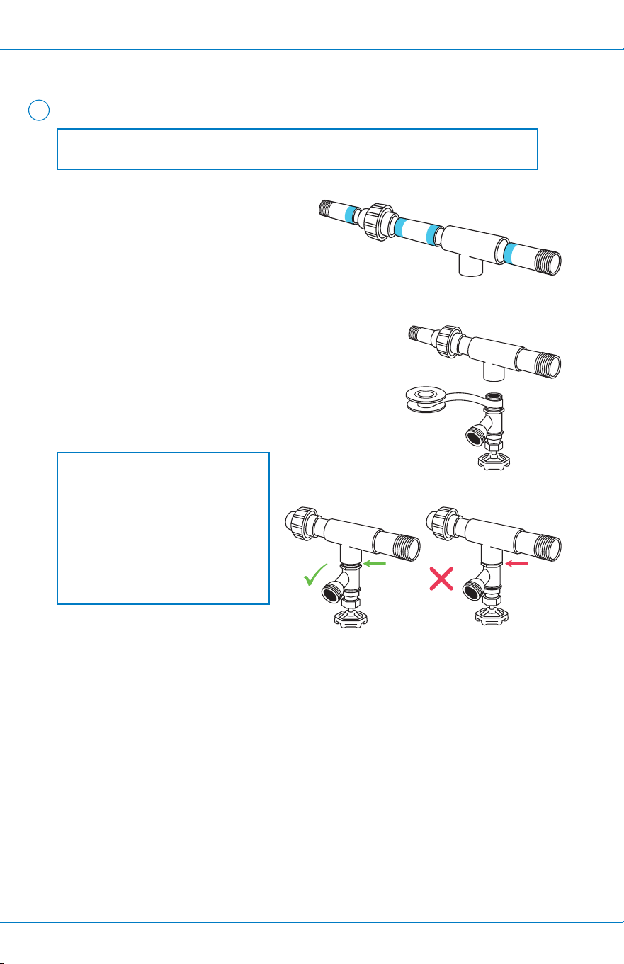
6
Assemble Drain Valve
1. Using PVC primer and glue,
assemble the piping as shown
to the right (Figure 1), applying
primer and glue. Ensure enough
glue cure time before running
water through the system.
2. Wrap the 1/2" male drain end 2-3 times with
plumber's tape (Figure 2).
3. Hand tighten the drain valve into the 1/2"
female threaded tee. Then, tighten 1-2
more turns with a wrench (Figure 3).
NOTE: All threads are NPT tapered pipe threads.
NOTE: DO NOT OVER TIGHTEN.
There should be a gap between
the drain valve threads and tee.
Tightening the 1/2" brass drain
valve more than 2 turns with a
wrench can cause the tee
to crack.
Figure 1
Figure 2
Figure 3
INSTALLATION STEPS
11
< Back To Table of Contents Next >
7
Congure System
1. Fit Rhino
®
tank and additional optional add-ons into the system at this time.
2. Attach the shut-o valve to your incoming water line.
3. Connect the threaded nipple from the shut-o valve outlet to the
20" Pre-Filter housing inlet with NSF certied plumber's tape.
4. Attach the lter wall bracket to the Pre-Filter housing with included screws.
Once this is complete, screw the support bracket to the wall.
5. Ensure all parts are owing through the "IN" port in the correct direction of
water ow.
6. Connect the threaded nipple from the Pre-Filter outlet to the union that is
attached to the Rhino
®
tank inlet.
7. Using the drain valve assembly from step 6, connect the drain valve assembly
to the union attached to the Rhino
®
tank outlet as well as the Post-Filter inlet
with included nipples.
8. Attach the Post-Filter bracket and housing to the wall, similar to the
Pre-Filter, and ensure all connections are tight.
9. Follow instructions in the separate UV Filter installation manual at this time to
mount and install the UV Filter.
>> Click here to view the UV Filter Owner's Manual.
Use PVC pipe, elbows, and reducers to connect from the Post-Filter to the
UV Filter.
10. If you have additional attachments, please reference those manuals before
the nal installation.
11. Once installation is complete, allow proper time for the glue to dry according
to manufacturer instructions.
NOTE: Additional materials may be needed to ensure Pre-Filter and Post-Filter
brackets are supported and properly secured to wall.
Shipping Guard
NOTE: If your Pre-Filter housing has a shipping guard
attached to it, remove the guard prior to assembly. If you
upgraded to the Low Maintenance Pre-Filter, remove plastic
wrapping from lter before installing. Filter is located inside
of the pre-assembled Pre-Filter housing. Once shipping
guard and/or plastic wrapping is removed, proceed to step 4.
INSTALLATION STEPS
12
< Back To Table of Contents Next >
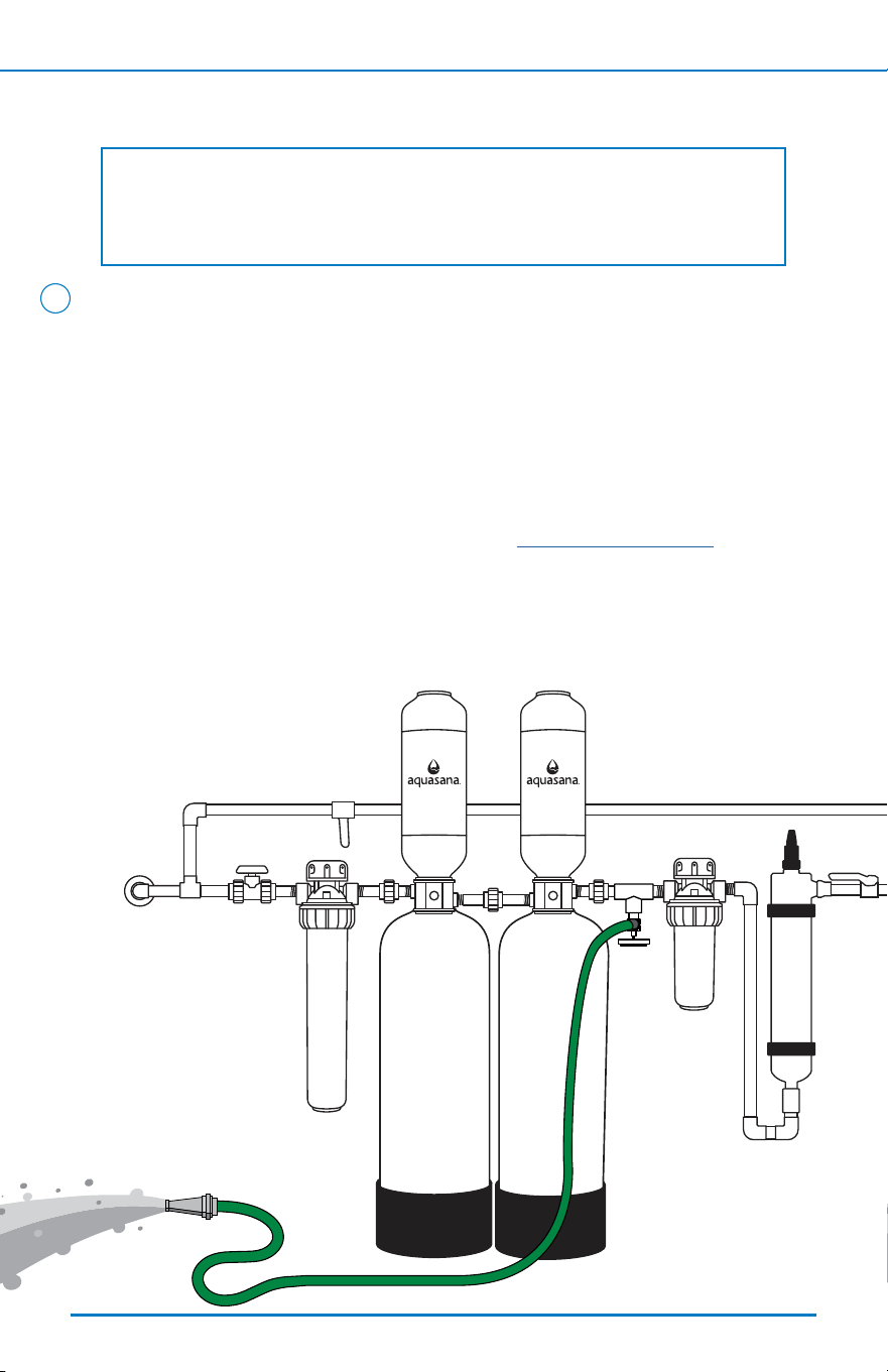
1. Connect a garden hose to the integrated drain valve and ensure the
drain valve is in the open position.
2. Ensure the garden hose outlet is directed towards a oor drain or
outdoor area. If a bypass loop is installed, ensure each shut-o valve
is in a closed position.
3. Slowly turn the water on from the initial shut-o valve and inspect for
leaks. If any leaks are detected, refer to the troubleshooting section.
If no leaks are detected, proceed with the ushing process.
4. Slowly turn the water on and allow discolored water to ow from the drain
valve into a suitable drainage area. The rst few gallons will appear black and
cloudy due to carbon nes.
Flush Your System
NOTE: It’s imperative that this system is ushed properly prior to system
water entering your house. The granular carbon used in the ltration tank
contains nes that must be ushed out prior to use.
8
INSTALLATION STEPS
13
< Back To Table of Contents Next >
1.
2.
3.
4.
5. After the initial 15-minute ushing, begin a period of "surge ushing" by turning
the water supply on for 30 seconds and then o for 30 seconds, repeating the
cycle for 15 minutes or until the initial surge of water is completely clear and
free from discoloration and cloudiness.
6. Final installation is complete. You may now close o the drain valve and enjoy
ltered water throughout your home.
Flush Your System (continued)
8
NOTE: Do not drink ushed water.

TROUBLESHOOTING GUIDE
14
< Back To Table of Contents Next >
Issue
Component is missing or
arrived damaged.
Call customer service @ 1 (866) 662-6885 option 1, and then
option 2, and then option 1. Please have order number,
model number, and pictures of damaged packaging and/or
damaged unit.
Tank leans to one side
or is not level
Lift the tank straight up and tap down on the ground until
the tank stands vertically. The bottom of the tank is round
and the boot allows the tank to stand upright.
Water leak at seam of
tank divider
Valve o-ring may not be placed properly or the top or bottom
tank may have loosened during shipping. Use rubber strap
wrench to tighten tanks. If leak continues, contact customer
service with a pre-recorded video of leak.
Water leak from Aquasana
ttings or drain valve
• Ensure tight connection – do not overtighten as that could
cause cracks and further leaking.
• Close the shut-o valve before the leak. Unscrew the
closest union and the threaded connection. Remove the
previous sealing tape from the tting and place more
sealing tape and or tighten the connection properly.
• Ensure all connections are properly tightened with a
wrench – do not over-tighten! If the problem persists,
contact customer service with pre-recorded video.
Water leak from pre/post
lter housing
• Ensure tight connection – do not overtighten as that could
cause cracks and further leaking.
• Tighten the housing further with the included wrench.
• If leak persists, close the shut-o valve before the leak.
Remove housing and lter. Clean o-ring, inside the housing,
and all threaded connections. Re-lubricate the o-ring and
reassemble it with a new lter.
• If a crack is visible and/or other methods do not stop the
leak, contact customer service.
Reduced water pressure
after installation
It is recommended that the sediment pre-lter be replaced
every 2 months depending on the amount of sediment
in your water supply. If the system has been working
properly and the pressure is slowing, it may be time to
change the sediment lter. Check the sediment lter
and replace if necessary.
Water appears gray or cloudy
Let air ush from water lines. Cloudy water will dissipate
over time (can take a week to a month) and is completely
harmless.
Taste/odor of water
did not improve
Ensure bypass loop is turned o and system shut-o valves
are open.
Resolution

MAINTENANCE
15
< Back To Table of Contents Next >
Cleaning
• The exterior of your ltration system can be cleaned with warm, soapy water.
Do not use any abrasive solution.
• Rinse well with clean water.
NOTE: Never use chemical cleaning products on the system’s exterior surface
as they may damage the housing.
FILTER REPLACEMENTS
16
< Back To Table of Contents Next >
Pre/Post-Filter Replacements
Whole House 20" Pre-Filter Cartridge Replacement
Replace every 2 months. Replace sooner if there is a noticeable decrease
in water ow through the lter system.
Whole House Low Maintenance Pre-Filter Cartridge Replacement
Replace every 6 months. Replace sooner if there is a noticeable decrease
in water ow through the lter system.
Whole House 10" Post-Filter Cartridge Replacement
Replace every 6 months. Replace sooner if there is a noticeable decrease
in water ow through the lter system.
Pre/Post-Housing Replacement
Replace every 5 years. To replace, call Customer Support.
How to change the Pre/Post-Filters:
1. Shut the lter system o at the shut-o
valve
A
. Place a 5 gallon bucket under the
system drain valve and open valve. This will relieve
water pressure and drain excess water.
2. Remove the blue lter housing by turning the lower ring to
the right, using the wrench supplied with your lter system.
Remove the used lter.
3. If necessary, clean the inside of the blue lter housing with
mild soapy water, rinse and dry.
4. Place new lter in the center of the blue lter housing.
5. Clean the housing o-ring and relubricate it with silicone grease.
Set the o-ring into the proper groove and reattach the housing
by screwing it back onto the top piece.
6. After reassembly, turn the system back on at the shut-o valve.
7. Run water, with the bucket still under the Pre-Filter. Check for leaks.
NOTE: DO NOT USE PETROLEUM JELLY as lubrication on the system
or o-rings.
A
NOTE: You must relieve the pressure in your system before
attempting to change any Pre-Filter or Post-Filter.

FILTER REPLACEMENTS
17
< Back To Table of Contents Next >
Specications
This lter system is designed and tested for use with genuine Aquasana
parts including replacement lters and all hardware. Use of parts from other
manufacturers may result in loss of contaminant reduction performance,
system damage, or failure. Use of parts from other manufacturers will also
void your warranty. For replacement parts, please visit aquasana.com.
Model: WH-WELL
System Replacements
20" Pre-Filter: EQ-303-20
10" Post-Filter: EQ-PFC.35
20" Low-Maintenance Pre-Filter: EQ-PRE-204-R
UV Lamp: AQ-UV-L330C
Quartz Sleeve: AQ-UV-Q330
Salt-Free Conditioner: WH-SFWC-T
FILTER REPLACEMENTS
18
< Back To Table of Contents Next >
Rhino
®
Tank Replacement
Shut O Water Supply
1. Turn o the main water source prior to tank replacement or turn o
the shut-o valve.
2. Place a 5 gallon bucket under the system drain valve and open valve.
This will relieve water pressure and drain excess water.
1
ELECTRICAL SHOCK HAZARD
If you have copper pipes - leave your grounding clamps installed. Do not disconnect
at any time while changing the tank. Failure to follow this instruction can result in
death or electric shock.
WARNING
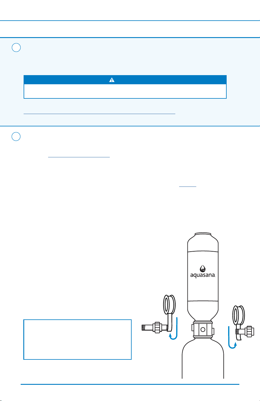
Remove Tank from System
1. Loosen the unions on both sides
of the Rhino
®
tank. Slide the entire
tank (pipe nipples and halves of unions
included) away from the system.
2. Unscrew the pipe nipples
from the tank.
3. Dispose of the old Rhino
®
tank properly.
2
1
1
2
2
NOTE: You must relieve the pressure in your system before attempting to
change the Rhino
®
tank.
FILTER REPLACEMENTS
19
< Back To Table of Contents
Reconnect Fittings
1. Clean the threads on the pipe nipples and
re-apply new NSF certied plumbers tape.
2. Connect pipe nipples to your new
Rhino
®
tank.
3
Rhino
®
Tank Replacement (continued)
Plumb In New Rhino
®
Tank
Slide the new tank back into the system
and re-attach the unions.
4
Next >
FILTER REPLACEMENTS
20
< Back Next >
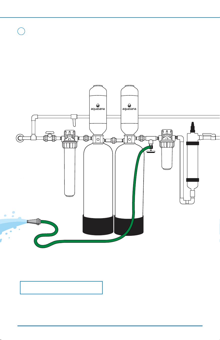
Flushing New Rhino
®
Tank
5
Rhino
®
Tank Replacement (continued)
1. Connect a garden hose to the integrated drain valve and ensure the
drain valve is in the open position.
2. Ensure the garden hose outlet is directed towards a oor drain or
outdoor area. If a bypass loop is installed, ensure each shut-o valve
is in a closed position.
3. Slowly turn the water on from the initial shut-o valve and inspect for
leaks. If any leaks are detected, refer to the troubleshooting guide on page
13. If no leaks are detected, proceed with the ushing process.
4. Slowly turn the water on and allow discolored water to ow from the drain
valve into a suitable drainage area. The rst few gallons will appear black and
cloudy due to carbon nes.
NOTE: It’s imperative that this system is ushed properly prior to system
water entering your house. The granular carbon used in the ltration tank
contains nes that must be ushed out prior to use.
To Table of Contents
FILTER REPLACEMENTS
21
< Back To Table of Contents Next >
1.
2.
3.
4.
5. After the initial 15-minute ushing, begin a period of "surge ushing" by turning
the water supply on for 30 seconds and then o for 30 seconds, repeating the
cycle for 15 minutes or until the initial surge of water is completely clear and
free from discoloration and cloudiness.
6. Final installation is complete. You may now close o the drain valve and enjoy
ltered water throughout your home.
Flushing Process (continued)
5
NOTE: Do not drink ushed water.
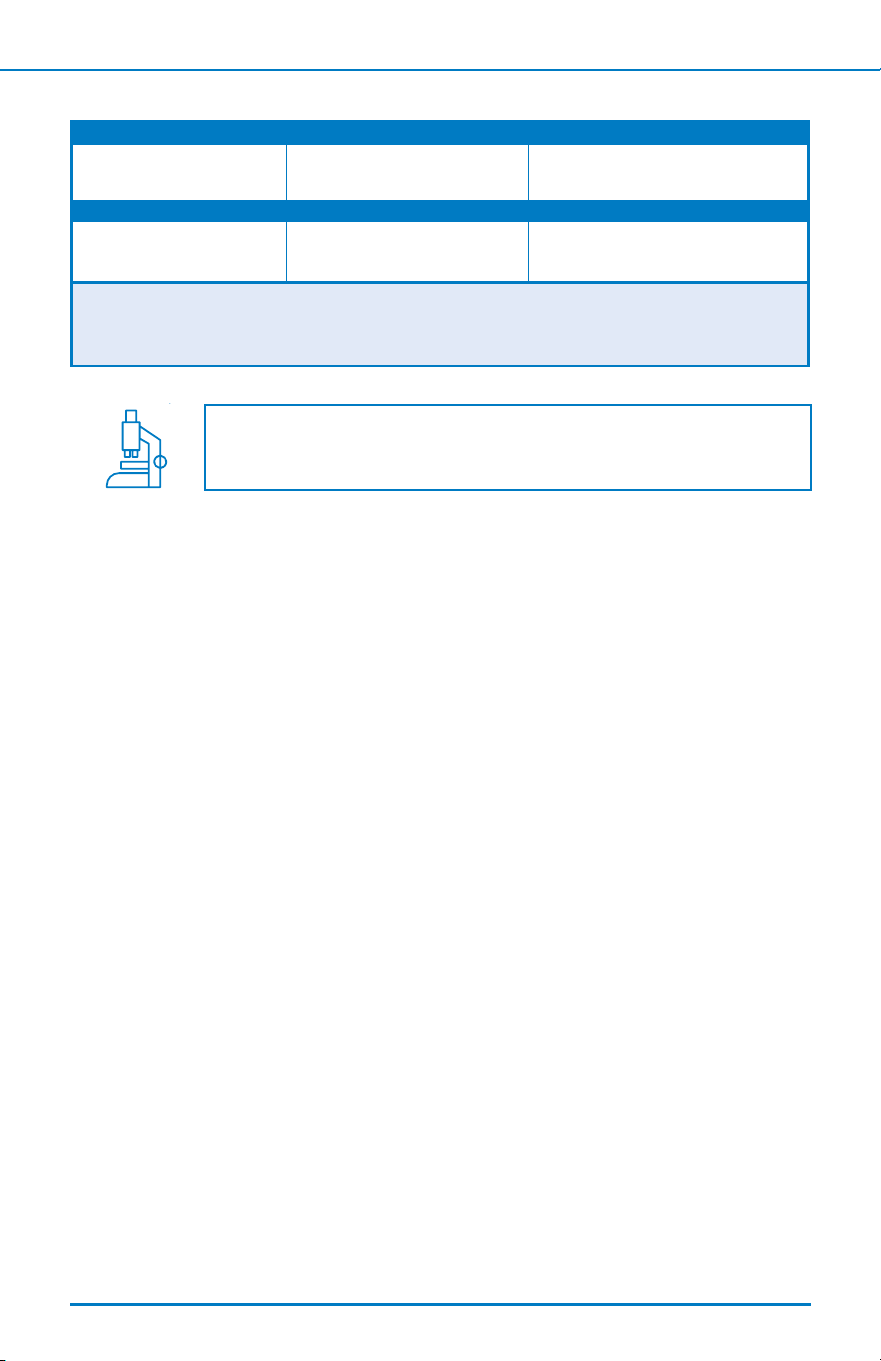
PERFORMANCE & CERTIFICATIONS
22
Model Replacement Rated Capacity
WH-WELL-UV WH-WELLR
500,000 gallons
1,892,705.89 liters
Operating Temp. Range Operating Pressure Range Rated Flow
40-90°F
4.44-32.2°C
20-100 psi
138-690 kPa
7.0 gpm
26.5 lpm
Manufactured by: Aquasana, Inc.
6310 Midway Road · Haltom City, Texas 76117
866-662-6885
Independently tested for the reduction of bacteria, viruses, cysts,
and other contaminants commonly found in well water.
< Back To Table of Contents Next >

< Back To Table of Contents Next >
22
This warranty only covers the products listed in the table above. If your system includes additional components, please refer to those
components' warranties.
Rhino
®
System Warranty Coverage
Model Lifespan/Capacity
WH-WELL-UV 5 years / 500,000 gallons
Installation Kit
(includes ttings purchased with original system)
12 months
Pre- and Post-Filter Housing Units 12 months
WHO IS COVERED
AQUASANA AND ITS SUPPLIERS, (herein collectively referred to
as “Manufacturer”) warrants to the owner of the home where the
water lter is initially installed (hereinafter “Owner”). The warranty
is restricted to the water lter used in a single-family residence in
the United States of America and is void if moved from the original
installation location. Registration of the product is not required
to receive warranty coverage as specied in this document. If you
purchased from an Aquasana-authorized reseller or dealer, proof
of purchase is required.
WHAT IS COVERED
This Warranty covers defects in materials or workmanship during
the limited warranty period of your of your Aquasana Rhino Whole
House Filtration System including sub-components purchased with
original system (may or may not include pre-lter, post-lter, and
ttings), except as provided below. The water lter is warranted
only when it is installed, operated and maintained in accordance
with the instructions accompanying the water lter found on
Aquasana.com. A water lter should be installed in such a manner
that, if the tank or any connection thereto should leak, the resulting
ow of water will not cause damage to the area in which it is
installed. For detailed instructions read the manual accompanying
the water lter and review drawings in the manual.
FOR HOW LONG
This warranty runs for months specied in chart below from the
date of purchase by a consumer (herinafter "Warranty Period").
No warranty coverage will be provided if the claimant is unable to
provide proof of purchase. Water conditions and use rates may
limit the functional lifespan of your lter. This Limited Warranty
does not extend to the full estimated life span of the lter.
WHAT AQUASANA WILL DO
1. If necessary, the Manufacturer will provide a replacement that
fullls the remaining estimated lifespan/capacity (see chart)
of your original purchase and send it to you with installation
instructions. If industry standards, product improvements or
product obsolescence prohibit Manufacturer from furnishing an
identical model replacement water lter under this warranty, the
Owner will be furnished with a new water lter of comparable
remaining capacity and functionality; however, the Owner will be
charged for the additional value of the item(s) which Manufacturer
has incorporated in the replacement water lter.
2. Component Part – If any component part proves to
Manufacturer’s satisfaction to be defective in material or
workmanship within the warranty period listed on the data
plate label, the Manufacturer will furnish the Owner with a
replacement for the defective part(s).
3. Return of Defective Water Filter and Component Parts –
Manufacturer reserves the right to examine the alleged defect in
the water lter or component part(s), and it will be the Owner’s
obligation to return the water lter and/or component part(s) to the
Manufacturer at the Manufacturers request.
a. When returning a water lter, it must include all component parts.
b. When returning component part(s), they must be individually
tagged and identied with the water lter’s model number,
date of purchase, and date of installation.
WHAT IS NOT COVERED
1. This Warranty applies only to products purchased from
authorized Aquasana resellers.
2. This warranty does not cover lter cartridges and any systems
that were not installed in compliance with the instructions or
that have been abused or operated incorrectly. This Warranty
applies only to products purchased from Aquasana or an
Aquasana-authorized reseller or dealer.
3. Except when specically prohibited by the applicable state
law, the Limited Warranty stated herein is in lieu of any
and all warranties, express or implied (whether written or
oral), including, but not limited to, the implied warranties of
merchantability and tness for a particular purpose.
4. Except when specically prohibited by the applicable state law, the
Manufacturer shall not be liable for any incidental, consequential,
special, or contingent damages or expenses, arising, directly or
indirectly, from any defect in the water lter of the use of the water
lter.
5. Manufacturer shall not be liable for any water damage arising,
directly or indirectly, from any defect in the water lter or
component part(s) or from its use.
6. Manufacturer shall not be liable for any damage or product
failures caused by any of the following:
• The water lter or any of its component parts have been
subject to misuse, alteration, neglect or accident.
• The water lter has not been installed in accordance with
the applicable local plumbing and/or building code(s) and/or
regulations or in their absence.
• The water lter is not installed, operated and maintained
in accordance with the printed Manufacturer’s instructions,
including if the water lter has any additional aftermarket
equipment introduced into the sealed system not approved by
the manufacturer.
• The water lter is exposed to highly corrosive conditions.
• The water lter is not continuously supplied with potable water.
• The water lter is not operated within the factory calibrated
temperature limits.
• The water lter is removed from its original installation location.
• The water lter is installed in direct sunlight or exposed to
freezing temperatures.
• The water lter or any of its component parts fail due to iron
or sediment build-up.
• Clogging due to purchaser’s failure to replace the Pre-Filter
cartridge.
• Damage caused by re, ood or acts of God.
• Damage caused by over-pressurization in the water line.
7. This warranty does not cover damage caused by the use of parts
that are not genuine Aquasana parts. This includes, but is not
limited to replacement lters, faucets, and/or diverter valves.
8. Except when specically prohibited by the applicable state law,
the Owner, and not the Manufacturer, shall be liable for and
shall pay for all charges for labor or other expenses incurred
in the removal, repair or replacement of the water lter or
any component part(s) claimed to be defective or any expense
incurred to remedy any defect in the product. Such charges may
include, but are not necessarily limited to:
a. All freight, shipping, handling and delivery costs of forwarding a
new water lter or replacement part(s) to the owner.
b. All costs necessary or incidental in removing the defective
water lter or component part(s) and installing a new water
lter or component part(s).
c. Any material required to complete, and/or permits required
for, installation of a new water lter or replacement part(s),
and
d. All costs necessary or incidental in returning the water
lter or component part(s) to a location designated by the
manufacturer.
9. This warranty provides specic legal rights and limitations, but
you may have other rights under applicable state law.
HOW TO GET SERVICE
To receive service under this Warranty, you must contact Aquasana
(A. O. Smith Water Treatment (North America), Inc.) at 1-866-662-
6885 or [email protected] within the Warranty Period to
describe the problem to a customer service representative who will
verify that the product is under warranty and determine whether
a part or the system will be replaced and whether you must
send back the unit. You will be required to provide both proof of
purchase and proper installation.
HOW STATE LAW APPLIES
This Warranty gives you specic rights and you may have other rights
which vary from state to state.
Rhino
®
Water Filter
Limited Warranty
23
Protect your investment and save money with Water for Life
®
.
Our Water for Life
®
program helps you protect the investment you’ve made in
your family’s health with an extended limited warranty on your new ltration
system, a 15% discount on replacement lters, and free shipping.
* Exclusions apply. Limited Warranty details are available at aquasana.com. Benets are for the term of Water for Life membership.
Free Shipping
Replacements shipped to
you right when you need
them – at no extra cost.
Discounted
Replacements
The only way to lock
in a 15% discount on
replacement lters.
Extended
Limited Warranty
Our performance promise
to you – free replacement
parts when needed.
*
No Contract
Free to join and cancel
anytime – no long-term
commitment required.
< Back
24
To Table of Contents
CONTACT US TO LEARN MORE
866-275-2319