
Wisen Innovation Technical Doc. No.2026 WiSenMeshWAN® Displacement & Temperature Interface Node - User Manual
www.wisencn.com Page - 1 - of 13
WisenMeshWAN® Displacement &
Temperature Interface Node
User Manual
6101
Wuxi Wisen Innovation Co., Ltd.
April 2026

Wisen Innovation Technical Doc. No.2026 WiSenMeshWAN® Displacement & Temperature Interface Node - User Manual
www.wisencn.com Page - 2 - of 13
Revision History and Clarification
Rev.
Issue Date
Revisions
Written By
Revised By
V1.0
21/04/2026
1st issue
Xinhu Nie
Dr. Yan Wu
Document Definition:
It defines the specifications (i.e., introduction, technical features, deployment and maintenance methods) of the
WiSenMeshWAN® Displacement & Temperature Node, which is one of the key components in WiSenMeshWAN®
Low Power, Intelligent, Wireless Sensor Network (WSN) system. It is responsible to:
Sample displacement (LVDT) and temperature (NTC thermistor) data from external sensors;
Form a time-synchronised Wireless Sensor Network with other nodes in the system;
Transmit the data packet to a gateway.
Scope:
Customer Site Project Managers and Engineers, Wisen Service Engineers, etc.

Wisen Innovation Technical Doc. No.2026 WiSenMeshWAN® Displacement & Temperature Interface Node - User Manual
www.wisencn.com Page - 3 - of 13
Table of Contents
1. Product Introduction ..............................................................................................................................................- 4 -
2. System Structure Layout .........................................................................................................................................- 5 -
3. Node & Radio Features ...........................................................................................................................................- 6 -
4. Terminologies .........................................................................................................................................................- 8 -
5. Operation Procedures .............................................................................................................................................- 8 -
5.1.System Deployment Notifications ..............................................................................................................- 8 -
5.2.Deployment Procedures .............................................................................................................................- 9 -
5.3.Mounting Options ......................................................................................................................................- 9 -
6. General Maintenance and Notification ................................................................................................................. - 10 -
7. Package and Accessories ....................................................................................................................................... - 11 -
8. Safety and Warning............................................................................................................................................... - 11 -
9. Contact ................................................................................................................................................................. - 12 -
Wisen Innovation Technical Doc. No.2026 WiSenMeshWAN® Displacement & Temperature Interface Node - User Manual
www.wisencn.com Page - 4 - of 13
1. Product Introduction
The WiSenMeshWAN® Displacement & Temperature Interface Node is one of the key products
in our patented WiSenMeshWAN® geotechnical safety monitoring system. Working together with the
WiSenMeshWAN® gateway product and external LVDT displacement sensor and NTC temperature sensor, it
intelligently delivers real-time displacement and temperature data to the information centre.
The WiSenMeshWAN® Displacement & Temperature Node operates using our core technology, i.e., the
WiSenMeshWAN® Low Power, Intelligent, Wireless Sensor Network protocol, together with its internal high precision
analogue sample module and power unit. This product satisfies the three fundamental identities of the system:
A. Network Life Span: to maximise battery life across the mesh network as a whole;
B. Network Data Arrival Rate: to minimise data packet loss;
C. Single Node Environmental Coverage: to maximise radio coverage.
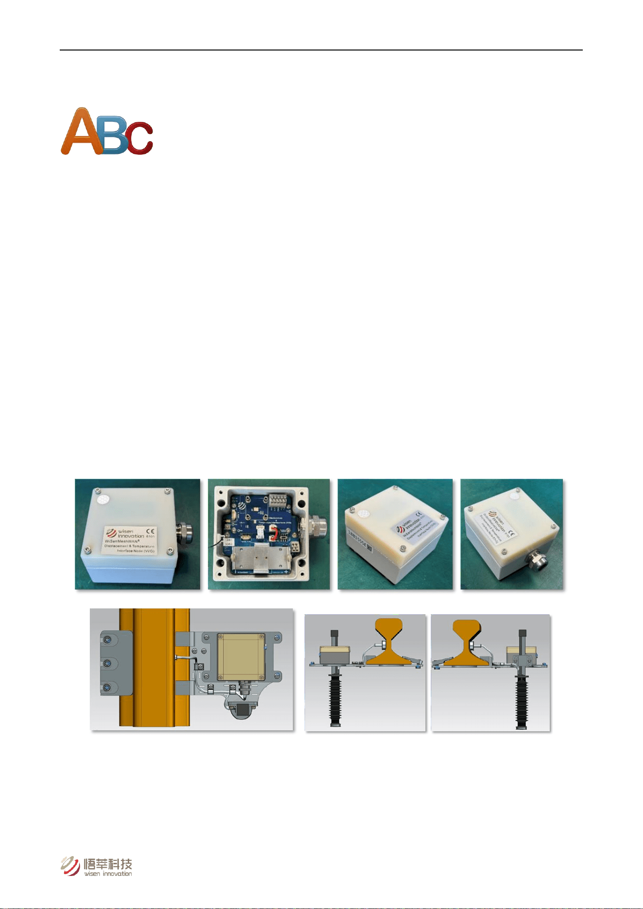
Our product has IP68 and is designed to work in a tough environment. It is small in size, reliable in performance, easy
for maintenance, has high precision during sampling, and has strong immunity to radio-interference. The node
supports external LVDT displacement sensor (0-200mm range) and NTC temperature sensor with magnetic clamp.
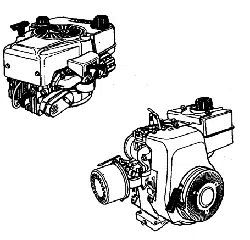
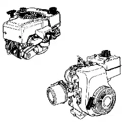
Top View Side View 1 Side View 2
Figure 1. Displacement & Temperature Interface Node – Overview.
Wisen Innovation Technical Doc. No.2026 WiSenMeshWAN® Displacement & Temperature Interface Node - User Manual
www.wisencn.com Page - 5 - of 13
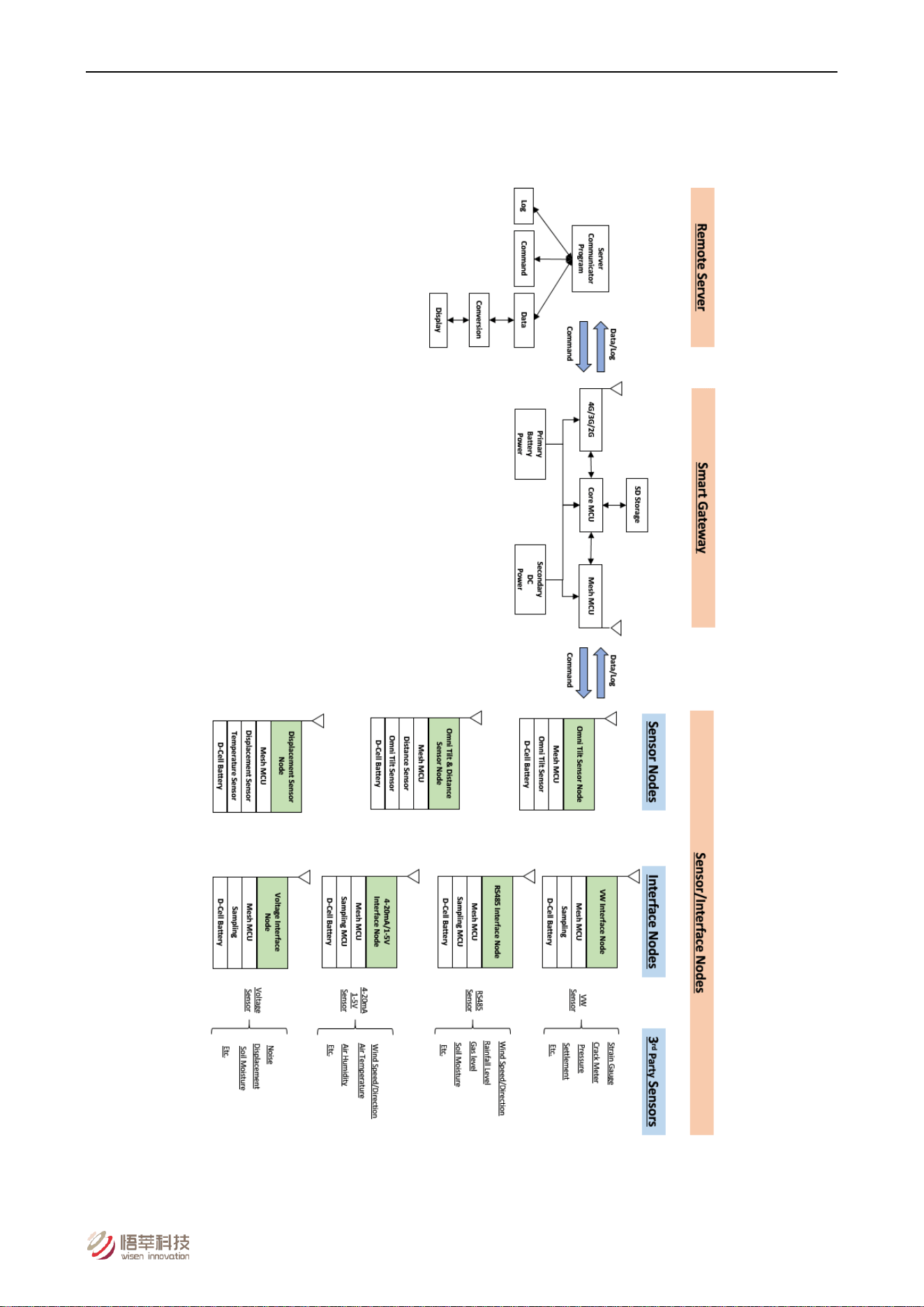
2. System Structure Layout
Figure 2. System Structure Layout.

Wisen Innovation Technical Doc. No.2026 WiSenMeshWAN® Displacement & Temperature Interface Node - User Manual
www.wisencn.com Page - 6 - of 13
3. Node & Radio Features
Node Features:
Basics
Battery Power
Qty. x 1 (3.6V Lithium primary D-Cell ER34615)
Mesh Stop Voltage
2.1VDC
Battery Connection
Standard Aluminium Battery Holder
Working Current
Max. 20mA (Typ. 12mA)
Alternative DC Input
3.6VDC (e.g., M002 – Wisen 3.6V External Battery Unit)
Local Storage
Min. 1500 Messages during Meshing at Mesh3.0 Protocol
Dimension (L x W x H)
100 x 100 x 60mm
Weight
Node: 0.4kg; Sensors (1m cable each): 0.25kg
Cable Gland
Qty. 1 x EMC-CMA12 for power; Qty. 1 x EMC-CMA20 for
displacement & temp sensors
Wire Connection
Spring type wiring terminal
External Primary Sensor
Displacement Sensor
Range: 0 to 50/100/150/200mm; Accuracy: 0.1%FS; Resolution:
0.0015%FS; IP68
NTC Temperature Sensor
Range: -40 to 85°C; Accuracy: Better than 0.2°C; Resolution: 0.1°C;
IP68; Magnetic clamp (45kg pull)
Standard System Parameter
Internal Temperature
Range: -40 to 85°C; Accuracy: ±0.1°C; Resolution: 0.1°C
Internal Humidity
Range: 0 to 100%RH; Accuracy: ±1.5%RH
Voltage
Accuracy: ±0.1V
WSN Interface
Mesh Wireless Interface
WiSenMeshWAN® Protocol

Wisen Innovation Technical Doc. No.2026 WiSenMeshWAN® Displacement & Temperature Interface Node - User Manual
www.wisencn.com Page - 7 - of 13
Basics
Industrial Standard
Casing and Painting Materials
Aluminium-Alloy Die Castings 12 (Epoxy Polyester Powder Coating)
IP Rating
≥ IP68
Operating Temperature
-40 to 85°C
Fire Proof
Approved
Radio Features:
* E.g., the radio link from a gateway to the 1
st
layer node is called the 1
st
hop.
FCC 915MHz System
CE 868MHz System
Radio Band
902-928MHz
865-868MHz
Central Frequency (Default)
905/910/915/920/925/922/923MHz
865.75/866.25/866.75/867.25MHz
Default Transmit Power
12dBm
14dBm
Transmit Power Range
5-20dBm
Receive Sensitivity
-112dBm
Bandwidth
500kHz
Transmission Speed
19.2kb/s
No. of Mesh Hop*
Supported
6 Hops
Sampling Interval
1-60mins
Wisen Innovation Technical Doc. No.2026 WiSenMeshWAN® Displacement & Temperature Interface Node - User Manual
www.wisencn.com Page - 8 - of 13
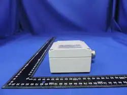
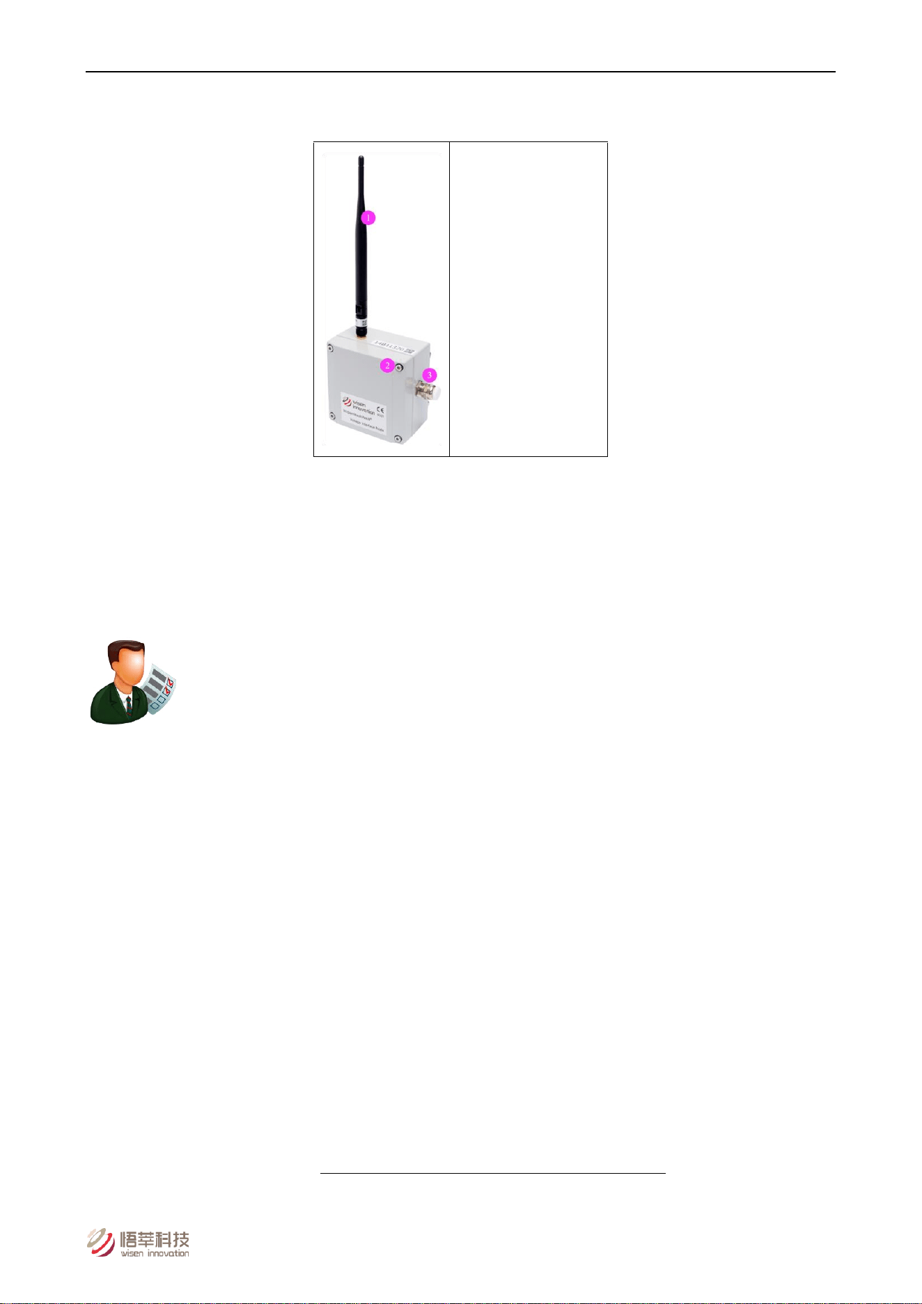
4. Terminologies
(1) Mesh Antenna
(2) M4 x 16 Lid Screw
(3) Cable Gland
Figure 3. Displacement & Temperature Interface Node Terminologies
5. Operation Procedures
5.1.System Deployment Notifications
1) Location: The deployment location of a Displacement & Temperature Interface Node is usually determined by the
required monitoring or inspection location;
2) All the Serial Numbers of a Unit must be recorded against their site references;
3) Before any Displacement & Temperature Interface Node is switched on, two tasks will need to be carried out:
A. The Displacement & Temperature sensors chosen by the customer must be connected to the node;
B. The connections between a customer chosen sensor and the node must strictly follow the rules stated in
this document;
C. A gateway must be deployed, powered on and proven to be working properly. Otherwise, the nodes will
need to be switched off, then switched on again after a gateway is switched on. So simply speaking, the rules
to follow to correctly deploy a WiSenMeshWAN® system are:
Gateway first, then nearby nodes, then further nodes.
4) During deployment, the Serial Number (SN) of a node and the orientation of the sensors deployed against their

Wisen Innovation Technical Doc. No.2026 WiSenMeshWAN® Displacement & Temperature Interface Node - User Manual
www.wisencn.com Page - 9 - of 13
site references must be recorded;
5) All the node should have its antenna point upwards.
5.2.Deployment Procedures
1) Open the box: Take the node out of the package and open its lid;
2) Insert Battery: By default, a node does not contain a D-Cell battery. Therefore the battery needs to be inserted.
Notice : +ve and –ve orientation must be correct, otherwise, the internal circuit may be damaged.
3) Antenna Installation: screw the antenna tightly onto the node;
4) Sensor Installation: To ensure a customer chosen sensor is deployed correctly onto a structure, please strictly
follow the corresponding manufacturer sensor instructions.
5) Sensor connections to Node:
A. Displacement: Brown (Power) to In2, Black (Signal) to In1, Blue (GND) to GND.
B. Temperature: Red to T+, White to T-.
C. Untighten the cable gland cover, insert the cable through the cable gland, then connect the wires to the
corresponding spring terminals according to the table below.
D. Once the wires are connected, please tighten the cable gland cover firmly to ensure its IP rating on that
channel.
Notice 1: The cable gland diameter of the Displacement & Temperature Interface Node is 3-6mm.
Notice 2: All required wires must be connected to minimise electrical interference and possible loss of precision.
Notice 3: Within any electrically noisy environment, nodes with sensors must be ≥ 0.3m away from the source of
the noise.
6) Power On: once all the sensors are connected, turn the switch on. You should see 3 LEDs flashing 3 times, which
means the node is on. Then switch off the node to save power if the gateway is off;
7) Tighten the 4 Cap-Hex-Head screws of the lid to secure the enclosure IP rating;
8) To validate the sensor data, please visit Wisen
Visualisation Platform for further details.
5.3.Mounting Options
The Displacement & Temperature Interface Node can be deployed with various methods. However, the principle is to
make sure it is firmly attached to the installation surface.

Wisen Innovation Technical Doc. No.2026 WiSenMeshWAN® Displacement & Temperature Interface Node - User Manual
www.wisencn.com Page - 10 - of 13
6. General Maintenance and Notification
1) Once the Displacement & Temperature Interface Node is installed in the field, please minimise any
man-made disturbance so that data quality can be maintained;
2) Radio communication will be impaired if the antenna is covered by metal or very moist soil material;
3) Due to the discharge characteristics of the recommended battery, a battery replacement should be carried out
when a node reported voltage reaches 2.7V, at which point you have approximately 3 weeks to change the
battery;
4) Our product will use all the possible capacity in a battery down to its stop (minimum) voltage, which has been
specified in the Features table. When this occurs, our WiSenMeshWAN® protocol will send you a warning, then it
will enter a deep sleep mode until a new battery is installed;
5) If the data from nodes are showing unexpected results or are not being sent back to the Wisen gateway, then
please carry out investigation using the following two stage procedure:
A. Remote Inspection of historical data, to identify the following:
a) Whether the heart-beat message has been sent back successfully at each time interval;
b) Whether the battery voltage is too low, if yes, please change the battery unit;
c) Whether the signal strength has become significantly weaker than before. If yes, please check the
antenna has been screwed on firmly.
B. On-site Inspection: If all the above are good, please arrange an on-site inspection to check:
a) Whether a Node has visible external damage;
b) Check the box lid to see if it is firmly tightened;
c) Whether the antenna is bent or damaged and that the node is not blocked by new construction, e.g.,
hoardings;
d) When possible, check that the signal strength is normal by using a spectrum analyser;
e) Open the lid, to see whether the battery is firmly attached to its holder;
f) Use a multi-meter to measure the battery voltage. If it is below the stop (minimum) voltage, replace
the battery.
g) Make sure the 3 or 4 wires are connected properly. If necessary, please disconnect the wires to inspect.
Notices :
i. Case One: If any change has been made from the list above, please inspect the data at the remote server;
Wisen Innovation Technical Doc. No.2026 WiSenMeshWAN® Displacement & Temperature Interface Node - User Manual
www.wisencn.com Page - 11 - of 13
ii. Case Two: If all the actions from the list above have not cured the problem, please contact Wisen. We will be
happy to help.
7. Package and Accessories
Standard:
No.
Items
Dimension (mm)
Qty.
1
WiSenMeshWAN® Displacement & Temperature Interface Node
100x100x60
1
2
Mesh Antenna
200
1
3
LVDT Displacement Sensor (with 1m cable)
-
1
4
NTC Temperature Sensor with magnetic clamp (1m cable)
-
1
5
Cap-Hex-Head Screw
M6x14
4
User Manual*
Downloadable from Wisen
Visualisation Platform.
Inspection Report*
8. Safety and Warning
Warning: Please read the following instructions carefully.
1)Operation Safety
Before taking any action, please read all the information provided carefully, and keep the guidance documents
safe;
Ensure that any procedures and installations are correctly carried out. The communication cable and the case
must be grounded;
This product has been designed to meet a certain water-proof level. However, it becomes water vulnerable when
the lid is open or if the cable gland has not been sealed properly.

Wisen Innovation Technical Doc. No.2026 WiSenMeshWAN® Displacement & Temperature Interface Node - User Manual
www.wisencn.com Page - 12 - of 13
2)Electric Safety
To install the battery into a holder, please follow the “+” (positive) and “-” (negative) signs in any Wisen product.
Wrong orientation of a battery could potentially cause unit damage.
Notice : The orientation of battery can vary among products;
When disconnecting the battery, please take special care not to apply excessive force, otherwise the battery
holder and the nearby circuitry may be damaged.
3)Warning
The battery in the product has a relatively high capacity, so please take special care during storage and usage;
This product must not be disassembled under any circumstances, to do so will void the warranty and may leave
the product in a dangerous state;
If all the above are not followed, the manufacturer cannot be responsible for any damage and injury caused to
the users.
4)Caution
Danger of explosion if battery is incorrectly replaced. Replace only with the type recommended by the
manufacturer;
When disposing of the batteries, please contact your local authorities or dealer and ask for the correct method of
disposal.
9. Contact
- Wuxi Wisen Innovation Co., Ltd.: www.wisencn.com
- Email: [email protected]

Wisen Innovation Technical Doc. No.2026 WiSenMeshWAN® Displacement & Temperature Interface Node - User Manual
www.wisencn.com Page - 13 - of 13
FCC Warning
This device complies with part 15 of the FCC Rules. Operation is subject to the following two conditions: (1) This device
may not cause harmful interference, and (2) this device must accept any interference received, including interference that
may cause undesired operation.
Any Changes or modifications not expressly approved by the party responsible for compliance could void the user's
authority to operate the equipment.
Note: This equipment has been tested and found to comply with the limits for a Class B digital device, pursuant to part 15
of the FCC Rules. These limits are designed to provide reasonable protection against harmful interference in a residential
installation. This equipment generates uses and can radiate radio frequency energy and, if not installed and used in
accordance with the instructions, may cause harmful interference to radio communications. However, there is no
guarantee that interference will not occur in a particular installation. If this equipment does cause harmful interference to
radio or television reception, which can be determined by turning the equipment off and on, the user is encouraged to try
to correct the interference by one or more of the following measures:
-Reorient or relocate the receiving antenna.
-Increase the separation between the equipment and receiver.
-Connect the equipment into an outlet on a circuit different from that to which the receiver is connected.
-Consult the dealer or an experienced radio/TV technician for help.
This equipment complies with FCC radiation exposure limits set forth for an uncontrolled environment. This equipment should be
installed and operated with minimum distance 20cm between the radiator & your body.
End of User Manual