1
Instruction Manual
PRINTED 1215 324258-002
KEEP THIS MANUAL IN THE POCKET ON HEATER FOR FUTURE REFERENCE
WHENEVER MAINTENANCE ADJUSTMENT OR SERVICE IS REQUIRED.
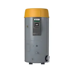
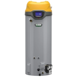
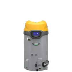
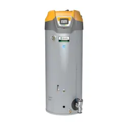
ULTRA LOW NOX COMMERCIAL GAS WATER HEATERS
• For Your Safety •
AN ODORANT IS ADDED TO THE GAS USED
BY THIS WATER HEATER.
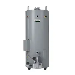
MODELS BL-80/BL-100
Series 100
INSTALLATION - OPERATION - SERVICE
- MAINTENANCE - LIMITED WARRANTY
PLACE THESE INSTRUCTIONS ADJACENT TO HEATER AND NOTIFY OWNER TO KEEP FOR FUTURE REFERENCE.

2
SAFE INSTALLATION, USE AND SERVICE...................... 3
APPROVALS ...................................................................... 3
GENERAL SAFETY INFORMATION .................................. 4
INTRODUCTION ................................................................ 5
Abbreviations Used ..................................................... 5
QualiedInstallerorServiceAgency........................... 5
PreparingfortheNewInstallation ............................... 5
INSTALLATION CONSIDERATIONS ................................. 6
RoughInDimensions .................................................. 6
Thermometers ............................................................. 7
FactstoConsiderAboutTheLocation ........................ 7
HighAltitude ................................................................ 8
Clearances .................................................................. 8
Insulation Blankets ...................................................... 9
Hard Water .................................................................. 9
CirculationPumps ....................................................... 9
INSTALLATION REQUIREMENTS .................................. 10
GasSupplySystems ................................................. 10
GasPressureRequirements ..................................... 10
SupplyGasRegulator ............................................... 10
MixingValves ............................................................ 10
WaterPiping .............................................................. 11
ClosedWaterSystems .............................................. 11
ThermalExpansion ................................................... 11
Temperature-PressureReliefValve ......................... 11
FillingtheWaterHeater ............................................. 12
AirRequirements....................................................... 12
UnconnedSpace ..................................................... 13
ConnedSpace ......................................................... 13
FreshAirOpeningsforConnedSpaces .................. 13
OutdoorAirThroughTwoOpenings .......................... 13
OutdoorAirThroughOneOpening ........................... 13
OutdoorAirThroughTwoHorizontalDucts ............... 14
OutdoorAirThroughTwoVerticalDucts ................... 14
AirFromOtherIndoorSpaces .................................. 14
Venting ...................................................................... 14
GasPiping ................................................................. 16
SedimentTraps ......................................................... 17
LIGHTING & OPERATING INSTRUCTIONS ................... 18
TEMPERATURE REGULATION ...................................... 19
FOR YOUR INFORMATION ............................................. 19
Start Up Conditions ................................................... 19
Operational Conditions .............................................. 20
PERIODIC MAINTENANCE ............................................. 21
VentingSystemInspection ........................................ 21
BurnerInspection ...................................................... 21
BurnerCleaning ........................................................ 21
Housekeeping ........................................................... 21
AnodeRodInspection ............................................... 22
Temperature-PressureReliefValveTest ................... 22
RECOMMENDED PROCEDURE FOR PERIODIC
REMOVAL OF LIME DEPOSITS FROM TANK
TYPE COMMERCIAL WATER HEATERS ........................ 22
DelimingSolvents...................................................... 23
TankCleanoutProcedure .......................................... 23
DelimingUsingFlo-JugMethod ................................ 23
DrainingandFlushing ............................................... 24
Service ...................................................................... 24
LEAKAGE CHECKPOINTS .............................................. 25
TROUBLESHOOTING GUIDELINES ............................... 26
WATER PIPING DIAGRAMS ............................................ 27
NOTES ............................................................................. 33
WARRANTY ..................................................................... 35
TABLE OF CONTENTS
3
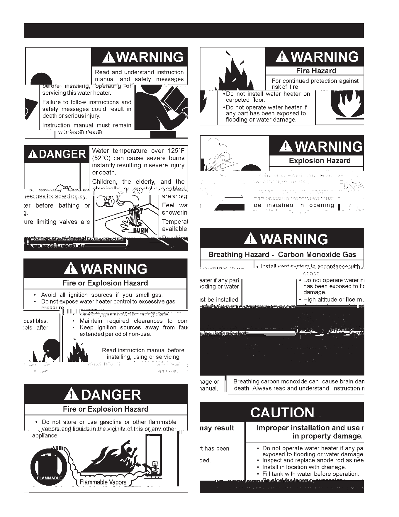
SAFE INSTALLATION, USE AND SERVICE
Theproperinstallation,useandservicingofthiswaterheaterisextremelyimportanttoyoursafetyandthesafetyofothers.
Manysafety-relatedmessagesandinstructionshavebeenprovidedinthismanualandonyourownwaterheatertowarnyouand
othersofapotentialinjuryhazard.Readandobeyallsafetymessagesandinstructionsthroughoutthismanual.Itisveryimportant
thatthemeaningofeachsafetymessageisunderstoodbyyouandotherswhoinstall,use,orservicethiswaterheater.
Allsafetymessageswillgenerallytellyouaboutthetypeofhazard,whatcanhappenifyoudonotfollowthesafetymessage,and
howtoavoidtheriskofinjury.
DANGER
WARNING
CAUTION
CAUTION
DANGER indicates an imminently
hazardous situation which, if not avoided,
will result in injury or death.
This is the safety alert symbol. It is used to alert you to
potential personal injury hazards. Obey all safety
messages that follow this symbol to avoid possible
injury or death.
WARNING indicates a potentially hazardous
situation which, if not avoided, could result
in injury or death.
CAUTION indicates a potentially hazardous
situation which, if not avoided, could result in
minor or moderate injury.
CAUTION used without the safety alert
symbol indicates a potentially hazardous
situation which, if not avoided, could result in
property damage.
APPROVALS
Low Lead Content
4
GENERAL SAFETY INFORMATION

5
ThankYouforpurchasingthiswaterheater.Properlyinstalledand
maintained,itshouldgiveyouyearsoftroublefreeservice.
ABBREVIATIONS USED
AbbreviationsFoundInThisInstructionManual:
• UL-UnderwritersLaboratoriesInc.
• ANSI-AmericanNationalStandardsInstitute
• NFPA-NationalFireProtectionAssociation
• ASME-AmericanSocietyofMechanicalEngineers
• AHRI-Air-Conditioning,HeatingandRefrigerationInstitute
• CAN - Canada
• EPACT-EnergyPolicyAct
• CSA-CanadianStandardsAssociation
This gas-fired water heater is design certified by Underwriters
LaboratoriesInc.underAmericanNationalStandard/CSAStandard
forGasWaterHeatersANSIZ21.10.3•CSA4.3(currentedition).
QUALIFIED INSTALLER OR SERVICE AGENCY
Installationandserviceofthiswaterheaterrequiresabilityequivalent
tothatofaQualiedAgency(asdenedbyANSIbelow)intheeld
involved. Installation skills such as plumbing, air supply, venting,
gassupplyandelectricalsupplyarerequiredinadditiontoelectrical
testingskillswhenperformingservice.
ANSIZ223.12006Sec.3.3.83:“QualiedAgency”-“Anyindividual,
rm, corporation or company that either in person or through a
representativeisengagedinandisresponsiblefor(a)theinstallation,
testingorreplacementofgaspipingor(b)theconnection,installation,
testing, repair or servicing of appliances and equipment; that is
experiencedinsuchwork;thatisfamiliarwithallprecautionsrequired;
and that has complied with all the requirements of the authority
havingjurisdiction.”
Ifyouarenotqualied(asdenedbyANSIabove)andlicensedor
certiedasrequiredbytheauthorityhavingjurisdictiontoperforma
giventaskdonotattempttoperformanyoftheproceduresdescribed
in this manual. If you do not understand the instructions given in
this manual do not attempttoperformany procedures outlined in
thismanual.
PREPARING FOR THE INSTALLATION
1. ReadtheGeneralSafetyInformationsection,page4ofthis
manual first and then the entire manual carefully. If you
don’tfollowthesafetyrules,thewaterheaterwillnotoperate
pr o p er l y.I t c oul d c auseD E AT H,S E R I OU S B O DI LYIN J U RY
AND/ORPROPERTYDAMAGE.
This manual contains instructions for the installation,
oper a t ion,andm a int e nanc eo fthe gas - f ir e dwa terh e ate r. It
alsocontainswarningsthroughoutthemanualthatyoumust
readandbeawareof.Allwarningsandallinstructionsare
essentialtotheproperoperationofthewaterheaterandyour
safety.Sincewecannotputeverythingonthefirstfewpages,
READ THE ENTIRE MANUAL BEFORE ATTEMPTING TO
INSTALL OR OPERATE THE WATER HEATER.
2.The installation must conform with these instructions and
thelocalcodeauthorityhavingjurisdiction.Intheabsence
oflocalcodes,theinstallationmustcomplywiththecurrent
editions of the National Fuel Gas Code, ANSI Z223.1/
NFPA54orCAN /CSA - B149.1theNaturalGasandPropane
Installation Code. All documents are available from the
CanadianStandardsAssociation,8501EastPleasantValley
Road, Cleveland, OH 44131. NFPA documents are also
available from the National Fire Protection Association, 1
BatterymarchPark,Quincy,MA02269.
3.If after reading this manual you have any questions or do
notunderstandanyportionoftheinstructions,callthelocal
gasutilityorthemanufacturerwhosenameappearsonthe
ratingplate.
4.Carefully plan the place where you are going to put the
water heater. Correct combustion, vent action, and vent
pipeinstallationareveryimportantinpreventingdeathfrom
possiblecarbonmonoxidepoisoningandfires,seeFigures
3 and 7.
Examinethelocationtoensurethewaterheaterc omplieswith
theFacttoConsiderAboutTheLocationsectioninthismanual.
5.For
6
ROUGH IN DIMENSIONS
INSTALLATION CONSIDERATIONS
FIGURE 1.
K
HOT WATER
OUTLET
DRAIN
VA LV E
HOT
COLD
TOP VIEW
L
GAS INLET
INSTALL IN ACCORDANCE WITH LOCAL CODES
DRAIN VALVE
K
COLD WATER
INLET
OUTER DOOR
(BURNER ASSEMBL Y BEHIND)
DRAFT HOOD
F
H
J
B
D
A
E
M
7
THERMOMETERS (Not Supplied)
Thermometersshouldbeobtainedandeldinstalled.
Thermometersareinstalledinthesystemasameansofdetecting
thetemperatureoftheoutletwatersupply.
ThisWaterHeaterhasbeendesigncertifiedascomplyingwith
ANSIZ21.10.3-CSA4.3currenteditionforwaterheatersandis
consideredsuitablefor:
Water (Potable) Heating and Space Heating: All models are
consideredsuitableforwater(potable)heatingandspaceheating.
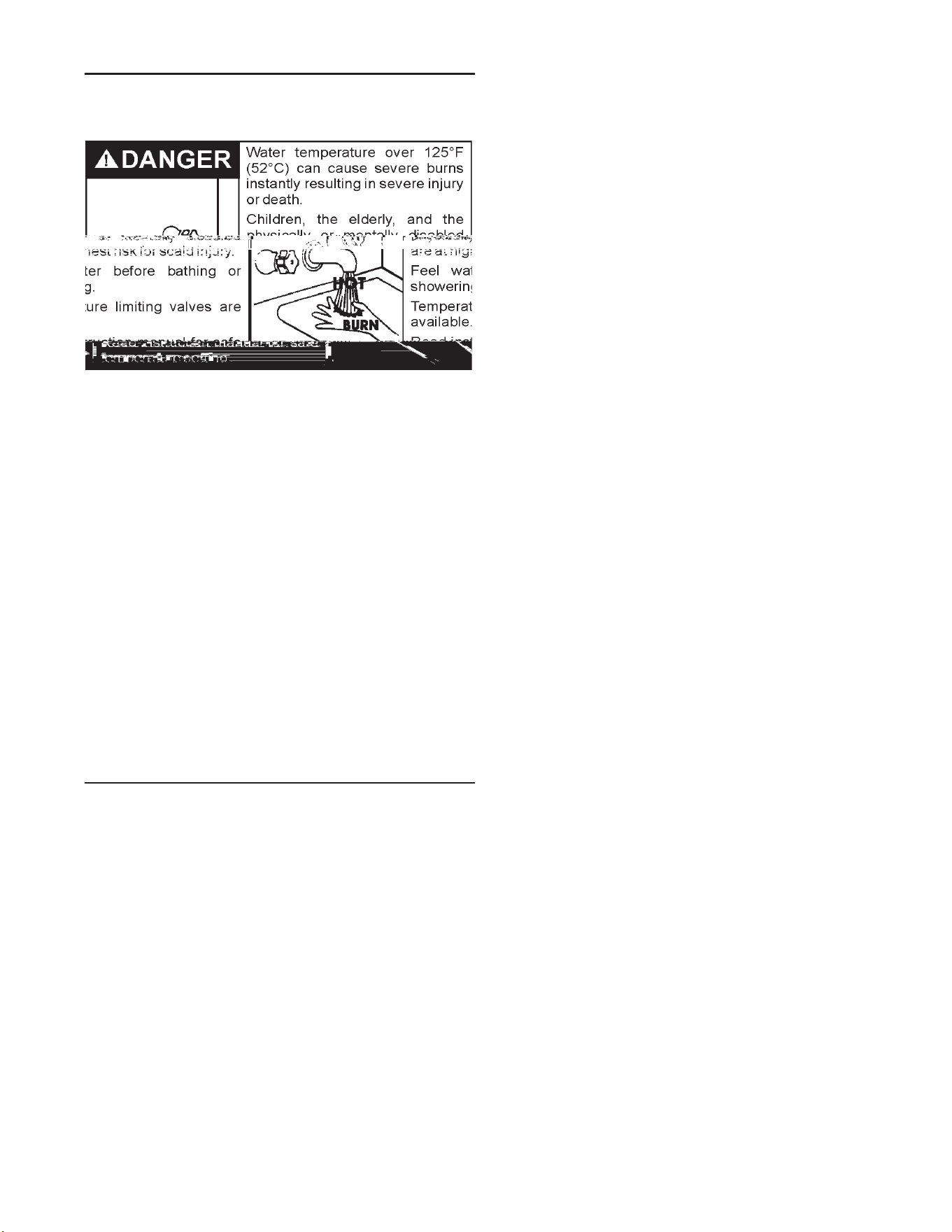
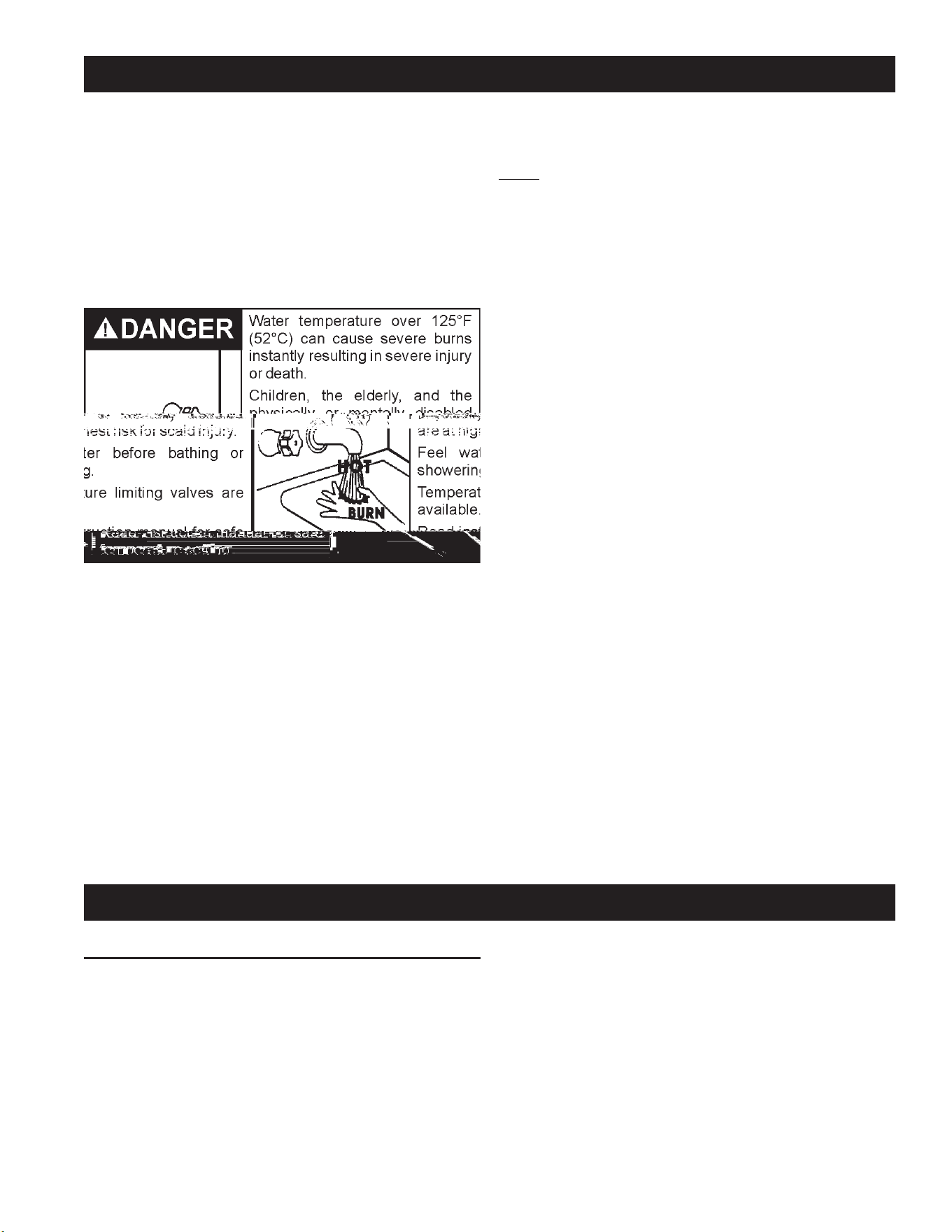
HOTTERWATERCANSCALD:
Waterheatersareintendedtoproducehotwater.Waterheatedtoa
temperaturewhichwillsatisfyspaceheating,clotheswashing,dish
washing,andothersanitizingneedscanscaldandpermanentlyinjure
youuponcontact.Somepeoplearemorelikelytobepermanently
injuredbyhotwaterthanothers.Theseincludetheelderly,children,
theinrm,orphysically/mentallyhandicapped.Ifanyone
8
usedinthesameroomorareacontainingagaswaterheaterorother
openameorsparkproducingappliance.NOTE:Flammablevaporsmay
bedrawnbyaircurrentsfromotherareasofthestructuretotheappliance.
Also, the water heater must be located and/or protected so it is not
subjecttophysicaldamagebyamovingvehicle.
Thiswaterheatermustnotbeinstalleddirectlyoncarpeting.Carpeting
mustbeprotectedbymetalorwoodpanelbeneaththewaterheater
extendingbeyondthefullwidthanddepthofthewaterheaterbyatleast
3”(76.2mm)inanydirection,orifthewaterheaterisinstalledinan
alcoveorcloset,theentireoormustbecoveredbythepanel.Failure
toheedthiswarningmayresultinarehazard.
HIGH ALTITUDE
Waterheaterscoveredinthismanualhavebeentestedandapproved
for installation at elevations up to 7,700 feet (2,347 m) above sea
level.Forinstallationabove7,700feet(2,347m),thewaterheater’s
Btuinputshouldbereducedattherateof4percentforeach1,000
feet(305m)abovesealevelwhichrequiresreplacementoftheburner
oriceinaccordancewiththeNationalFuelGasCodeANSIZ223.1/
NFPA 54 or the Natural Gas and Propane Installation Code CAN/
CSAB149.1.Contactyourlocalgassupplierforfurtherinformation.
Failuretoreplacethestandardoricewiththeproperhighaltitude
orice when installed

9
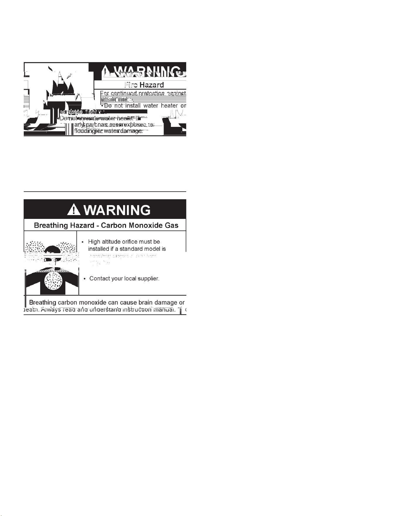
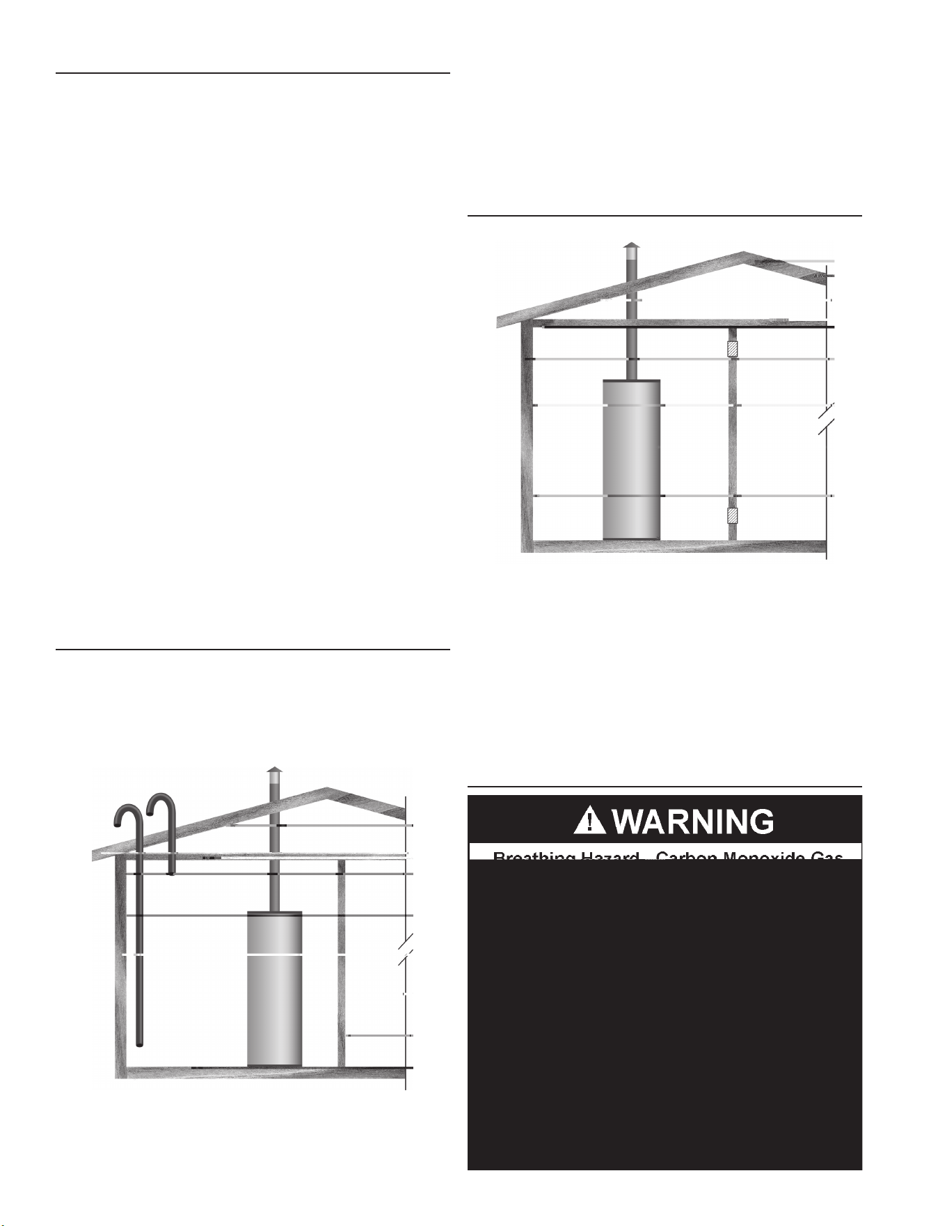
INSULATION BLANKETS
Do not obstruct water heater air intake
with insulating blanket.
Gas and carbon monoxide detectors
are available.
Install water heater in accordance with
the instruction manual.
Breathing carbon monoxide can cause brain damage or
death. Always read and understand instruction manual.
Breathing Hazard - Carbon Monoxide Gas

10
GAS SUPPLY SYSTEMS
Low pressure building gas supply systems are dened as those
systemsthatcannotunderanycircumstancesexceed14”W.C.
(1/2PSIGauge).Thesesystemsdonotrequirepressureregulation.
Measurementsshouldbetakentoinsurethatgaspressuresarestable
andfallwithintherequirementsstatedonthewaterheaterratingplate.
readings should be taken with all gas burning equipment off (static
pressure)andwithallgasburningequipmentrunningatmaximumrate
(dynamicpressure).Thegassupplypressuremustbestablewithin1.5”
W.C. from static todynamicpressuretoprovide good performance.
Pressuredropsthatexceed1.5”W.C.maycauseroughstarting,noisy
combustionornuisanceoutages.Increasesorspikesinstaticpressure
duringoffcyclesmaycausefailuretoigniteorinseverecasesdamage
toappliancegasvalves.Ifyourlowpressuresystemdoesnotmeet
theserequirements,theinstallerisresponsibleforthecorrections.
HighPressurebuildingsupplysystemsusepressuresthatexceed
14” W.C. (1/2 PSI Gauge). These systems must use eld supplied
regulatorsto lower the gaspressure to less than 14” W.C. (1/2 PSI
Gauge).Appliancesrequiregasregulatorsthatareproperlysizedforthe
waterheaterinputanddelivertheratingplatespeciedpressures.Gas
supplysystemswherepressureexceeds5PSIoftenrequiremultiple
regulatorstoachievedesiredpressures.Systemsinexcessof5PSI
building pressure should be designed by gas delivery professionals
forbestperformance.Waterheatersconnectedtogassupplysystems
thatexceed14”W.C.(1/2PSIGauge)atanytimemustbeequipped
withagassupplyregulator.
GAS PRESSURE REQUIREMENTS
BL-100naturalgasmodelrequiresaminimumgassupplypressureof
5”w.c.(1.25kPa);BL-80naturalgasmodelrequiresaminimumgas
supplypressureof6”w.c.(1.49kPa).Theminimumsupplypressure
is measured while gas is owing (dynamic pressure). The supply
pressure(dynamic)shouldneverfallbelowthespeciedminimum
supplypressure.Thesupplypressureshouldbemeasuredwithallgas
redappliancesconnectedtothecommonmainringatfullcapacity.If
thesupplypressuredropsmorethan1.5”W.C.(0.37kPa)asgasbegins
toowtothewaterheaterthenthesupplygassystemincludingthe
gaslineand/orthegasregulatormayberestrictedorundersized.See
SupplyGasregulatorsectionandGasPipingsectionofthismanual.
Thegasvalveonallmodelshasamaximumgassupplypressurelimit
of14” W.C.
valve
11
WATER PIPING
WATER (POTABLE) HEATING AND SPACE HEATING
Thiswaterheatershallnotbeconnectedtoanyheatingsystems
orcomponent(s)usedwithanon-potablewaterheatingappliance.
Allpipingcomponentsconnectedtothis unit for space heating
applicationsshallbesuitableforusewithpotablewater.
Toxicchemicals,suchasthoseusedforboilertreatmentshallnot
beintroducedintothissystem.
Whenthesystemrequireswaterforspaceheatingattemperatures
higherthanrequiredfordomesticwaterpurposes,amixingvalve
mustbeinstalled.PleaserefertoFigure6forsuggestedpiping
arrangement.
Thesewaterheaterscannotbeusedinspaceheatingapplications
only.
CLOSED WATER SYSTEMS
Water supply systems may, because of code requirements or
such conditions as high line pressure, among others, have
installed devices such as pressure reducing valves, check
valves,andbackflowpreventers.Devicessuchasthesecause
thewatersystemtobeaclosedsystem.
THERMAL EXPANSION
Aswaterisheated,itexpands(thermalexpansion).Inaclosed
systemthevolumeof waterwillgrowwhenit isheated.Asthe
volumeofwatergrowstherewillbeacorrespondingincreasein
water pressure due to thermal expansion. Thermal expansion
cancauseprematuretankfailure(leakage).Thistypeoffailure
is not covered under the limited warranty. Thermal expansion
canalso cause intermittent Temperature-Pressure ReliefValve
operation: water discharged from the valve due to excessive
pressurebuildup.Thisconditionisnotcoveredunderthelimited
warranty.TheTemperature-PressureReliefValveisnotintended
fortheconstantreliefofthermalexpansion.
A properly sized thermal expansion tank must be installed on
all closed systems to control the harmful effects of thermal
expansion.Contactalocalplumbingservicetechniciantohave
athermalexpansiontankinstalled.
FIGURE 7.
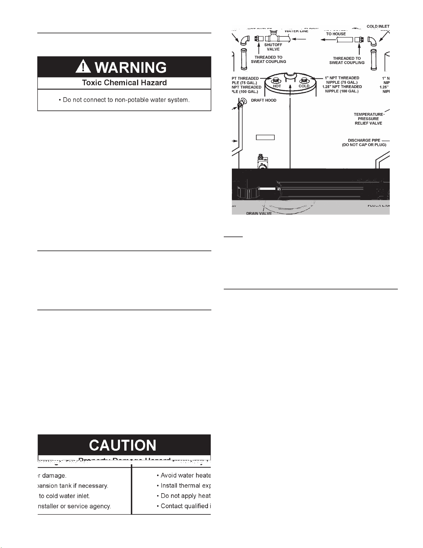
NOTE: To protect against untimely corrosion of hot and cold
waterttings, itisstronglyrecommended thatdi-electricunions
orcouplingsbeinstalledonthiswaterheaterwhenconnectedto
copperpipe.
Figure7showsthetypicalattachmentofthewaterpipingtothe
water heater.
12
NOTE: In addition to the factory installed Temperature-Pressure
Relief Valve on the water heater, each remote storage tank that
maybeinstalledandpipedtoawaterheatingappliancemustalso
have its own properly sized, rated and approved Temperature-
PressureReliefValveinstalled.Callthetollfreetechnicalsupport
phonenumberlistedonthebackcoverofthismanualfortechnical
assistanceinsizingaTemperature-PressureReliefValveforremote
storagetanks.
For safe operation of the water heater, the Temperature-Pressure
ReliefValvemustnotberemovedfromitsdesignatedopeningnor
plugged.TheTemperature-PressureReliefValvemustbeinstalled
directlyintothettingofthewaterheaterdesignedforthereliefvalve.
Installdischargepipingsothatanydischargewillexitthepipewithin
6inches(15.2cm)aboveanadequateoordrain,orexternaltothe
building.Incoldclimatesitisrecommendedthatitbeterminatedat
anadequatedraininsidethebuilding.Becertainthatnocontactis
madewithanyliveelectricalpart.Thedischargeopeningmustnot
beblockedorreducedinsizeunderanycircumstances.Excessive
length,over30feet(9.14m),oruseofmorethanfourelbowscan
causerestrictionandreducethedischargecapacityofthevalve.
No valve or other obstruction is to be placed between the
Temperature-PressureReliefValve andthetank. Donotconnect
dischargepipingdirectlytothedrainunlessa6”(15.2cm)airgapis
provided.Topreventbodilyinjury,hazardtolife,orpropertydamage,
the relief valve must be allowed to discharge water in adequate
quantitiesshouldcircumstancesdemand.Ifthedischargepipeis
notconnectedto a drain or other suitable means, thewaterow
maycausepropertydamage.
Water Damage Hazard
•
Temperature-Pressure Relief Valve discharge
pipe must terminate at adequate drain.
CAUTION
T&P Valve Discharge Pipe Requirements:
• Shallnotbesmallerinsizethantheoutletpipesizeofthevalve,
orhaveanyreducingcouplingsorotherrestrictions.
• Shallnotbepluggedorblocked.
• Shallnotbeexposedtofreezingtemperatures.
• Shallbeofmateriallistedforhotwaterdistribution.
• Shallbeinstalledsoastoallowcompletedrainageofboththe
Temperature-PressureReliefValveandthedischargepipe.
• Mustterminateamaximumofsixinchesaboveaoordrain
orexternaltobuilding.Incoldclimates,itisrecommended
thatdischargepipebeterminatedatanadequatedraininside
building.
• Shallnothaveanyvalveorotherobstructionbetweenthe
reliefvalveandthedrain.

13
amountofcombustionaircanresultinareorexplosionandcauseproperty
damage,seriousbodilyinjuryordeath.
UNCONFINED SPACE
An Unconfined Space is one whose volumeis not lessthan 50
cubic feet per 1,000 Btu/hr (4.8 cubic meters per kW) of the
totalinputratingofallappliancesinstalledinthespace.Rooms
communicating directly with the space, in which the appliances
are installed, through openings not furnished with doors, are
consideredapartoftheunconfinedspace.
Makeupairrequirementsfortheoperationofexhaustfans,kitchen
ventilation systems, clothes dryers and fireplaces shall also be
considered in determining the adequacy of a space to provide
combustion,ventilationanddilutionair.
UNUSUALLY TIGHT CONSTRUCTION
Inunconfinedspacesinbuildings,infiltrationmaybeadequateto
provideairforcombustion,ventilationanddilutionoffluegases.
However,inbuildingsofunusuallytightconstruction(forexample,
weatherstripping,heavilyinsulated,caulked,vaporbarrier,etc.)
additionalair must be provided using the methods described in
theConfinedSpacesectionthatfollows.
CONFINED SPACE
AConnedSpaceisonewhosevolumeislessthan50cubicfeetper
1,000Btu/hr(4.8cubicmetersperkW)ofthetotalinputratingofall
appliancesinstalledinthespace.
Openingsmustbeinstalledtoprovidefreshairforcombustion,ventilation
and dilution in conned spaces. The required size for the openings is
dependentonthemethodusedtoprovidefreshairtotheconnedspace
andthetotalBtu/hrinputratingofallappliancesinstalledinthespace.
DIRECT VENT APPLIANCES
Appliances installed in a Direct Vent conguration that derive all
air for combustion from the outdoor atmosphere through sealed
intakeair piping are not factored inthe total appliance input Btu/hr
calculationsusedtodeterminethesizeofopeningsprovidingfresh
airintoconnedspaces.
EXHAUST FANS
Whereexhaustfansareinstalled,additionalairshallbeprovided
toreplacetheexhaustedair.Whenanexhaustfanisinstalledin
thesamespacewithawaterheater,sufficientopeningstoprovide
freshairmustbeprovidedthataccommodatetherequirements
for all appliancesintheroomandthe exhaustfan. Undersized
openingswillcauseairtobedrawnintotheroomthroughthewater
heater’sventsystemcausingpoorcombustion.Sooting,serious
damagetothewaterheaterandtheriskoffireorexplosionmay
result.Itcanalsocreateariskofasphyxiation.
LOUVERS AND GRILLES
Thefreeareasofthefreshairopeningsintheinstructionsthatfollowdonot
takeintoaccountthepresenceoflouvers,grillesorscreensintheopenings.
Therequiredsizeofopeningsforcombustion,ventilationanddilution
airshallbebasedonthe“netfreearea”ofeachopening.Wherethe
freeareathroughadesignoflouverorgrilleorscreenisknown,itshall
beusedincalculatingthesizeofopeningrequiredtoprovidethefree
areaspecied.Wherethelouverandgrilledesignandfreeareaarenot
known,itshallbeassumedthatwoodlouverswillhave25%freearea
andmetallouversandgrilleswillhave75%freearea.Nonmotorized
louversandgrillesshallbexedintheopenposition.
FRESH AIR OPENINGS FOR CONFINED SPACES
The following instructions shall be used to calculate the size,
number and placement of openings providing fresh air for
combustion, ventilation and dilution in confined spaces. The
illustrationsshowninthissectionofthemanualareareference
for the openings that provide fresh air into confined spaces
only.Do not refer to these illustrations for the purpose of vent
installation. See Venting Installation on page 14 for complete
ventinginstallationinstructions.
OUTDOOR AIR THROUGH TWO OPENINGS
14
OUTDOOR AIR THROUGH TWO HORIZONTAL DUCTS
FIGURE 10.
Theconnedspaceshallbeprovidedwithtwopermanenthorizontal
ducts, one commencing within 12 inches (300 mm) of the top and
one commencing within 12 inches (300 mm) of the bottom of the
enclosure.Thehorizontalductsshallcommunicatedirectlywiththe
outdoors.SeeFigure10.
Eachductopeningshallhaveaminimumfreeareaof1squareinch
per2,000Btu/hr(1100mm2perkW)oftheaggregateinputratingof
allappliancesinstalledintheenclosure.
Whenductsareused,theyshallbeofthesamecrosssectionalarea
asthefreeareaoftheopeningstowhichtheyconnect.Theminimum
dimensionofrectangularairductsshallbenotlessthan3inches.
OUTDOOR AIR THROUGH TWO VERTICAL DUCTS
The illustrations shown in this section of the manual are a
reference for the openings that provide fresh air into conned
spacesonly.
DO NOT refer to these illustrations for the purpose of vent
installation. See Venting Installation on page 14 for complete
ventinginstallationinstructions.
FIGURE 11.
The conned space shall be provided with two permanent vertical
ducts, one commencing within 12 inches (300 mm) of the top and
one commencing within 12 inches (300 mm) of the bottom of the
enclosure. The vertical ducts shall communicate directly with the
outdoors.SeeFigure11.
Eachductopeningshallhaveaminimumfreeareaof1squareinch
per4,000Btu/hr(550mm2perkW)oftheaggregateinputratingof
allappliancesinstalledintheenclosure.
Whenductsareused,theyshallbeofthesamecrosssectionalarea
asthefreeareaoftheopeningstowhichtheyconnect.Theminimum
dimensionofrectangularairductsshallbenotlessthan3inches.
AIR FROM OTHER INDOOR SPACES
FIGURE 12.
Theconnedspaceshallbeprovidedwithtwopermanentopenings,
one commencing within 12 inches (300 mm) of the top and one
commencingwithin12inches(300mm)ofthebottomoftheenclosure.
SeeFigure12.
Eachopeningshallcommunicatedirectlywithanadditionalroom(s)
ofsufcientvolumesothatthecombinedvolumeofallspacesmeets
thecriteriaforanUnconnedSpace.
Eachopeningshallhaveaminimumfreeareaof1squareinchper
1,000Btu/hr(2200mm2perkW)oftheaggregateinputratingofall
appliancesinstalledintheenclosure.Eachopeningshallnotbeless
than100squareinches(645cm2).
VENTING

15
If the water heater is being installed as a replacement for an
existingheaterinpre-existingventing,athoroughinspectionof
existingventingsystemmustbeperformedpriortoanyinstallation
work.
VENT DAMPERS - Any vent damper, whether it is operated
thermallyorother wisemustberemovedifitsuseinhibitsproper
draftingofthewaterheater.
Thermally OperatedVent Dampers:thisgas-firedwater heater
has a thermal efficiency at or above 80% which may produce
a relatively low flue gas temperature. Such temperatures may
not be high enough to properly open thermally operated vent
dampers.Thiswouldcausespillageofthefluegasesandmay
cause carbon monoxide poisoning. Vent dampers must bear
evidenceofcertificationascomplyingwiththecurrenteditionof
th eA m er i c a n N a t io n a l S t an d a r d A N S I Z 21. 6 6C G A 6 .14(c o ve r i ng
electrically and mechanically actuated vent dampers). Before
installation of any vent damper,consultthe local gas utilityfor
furtherinformation.
Toinsurep r o p erve ntin goft h i s g a s - f i r e dwat e rheater, t h ec o r r e c t
ventpipediametermustbeutilized.Anyadditionsordeletions
ofothergasappliancesonacommonventwiththiswaterheater
mayadverselyaffecttheoperationofthewaterheater.Consult
yourgassupplierifanysuchchangesareplanned.
Forproperventingincertaininstallations,alargerdiametervent
pipemaybenecessary.Consultyourgassuppliertoaidyouin
determiningtheproperventingforyourwaterheaterfromthevent
tablesinthecurrenteditionoftheNationalFuelFl
16
GAS PIPING
Contact your local gas service company to ensure that adequate
gasservice is available and to review applicable installation codes
foryourarea.
SizethemaingaslineinaccordancewithTable3.Theguresshown
areforstraightlengthsofpipeat0.5in.W.C.pressuredrop,whichis
considerednormalforlowpressuresystems.Note:Fittingssuchas
elbows,teesandline regulatorswilladdtothepipepressure drop.
AlsorefertothecurrenteditionsoftheNationalFuelGasCode(NFPA
54)orNaturalGasandPropaneInstallationCode(CAN/CSAB149.1).
Makesuregassuppliedissametypelistedonmodelratingplate.The
inletgaspressuremustnotexceed14inchwatercolumn(2.6kPa)
fornaturalandpropane(L.P.)gas.Theminimuminletgaspressure
shownonratingplateisthatwhichwillpermitringatratedinput.
Ifthegascontrolvalveissubjectedtopressuresexceeding1/2pound
persquareinch(3.5kPa),thedamagetothegascontrolvalvecould
resultinareorexplosionfromleakinggas.
Ifthemaingaslineshut-offservingallgasappliancesisused,also
turn“off”thegasat each appliance. Leave allgas appliances shut
“off”untilthewaterheaterinstallationiscomplete.
Agaslineofsufcientsizemustberuntothewaterheater.Consult
thecurrenteditionofNationalFuelGasCodeANSIZ223.1/NFPA54
ortheNaturalGasandPropaneInstallationCodeCAN/CSAB149.1
andyourgassupplierconcerningpipesize.
Theremustbe:
• A readily accessible manual shut off valve in the gas supply line
servingthewaterheater,and
• Asedimenttrapaheadofthegascontrolvalvetohelppreventdirt
andforeignmaterialsfromenteringthegascontrolvalve.
• Aexiblegasconnectororagroundjointunionbetweentheshut
offvalveandcontrolvalvetopermitservicingoftheunit.
Besuretocheckallthegaspipingforleaksbeforelightingthewater
heater.Useasoapywatersolution,notamatchoropename.Rinse
offsoapysolutionandwipedry.
The minimum inlet gas pressure shown on the rating plate is that
whichwillpermitringattheratedinput.
TABLE 3. GAS SUPPLY LINE SIZES (IN INCHES)*
MAXIMUM CAPACITY OF PIPE IN CUBIC FEET PER HOUR
17
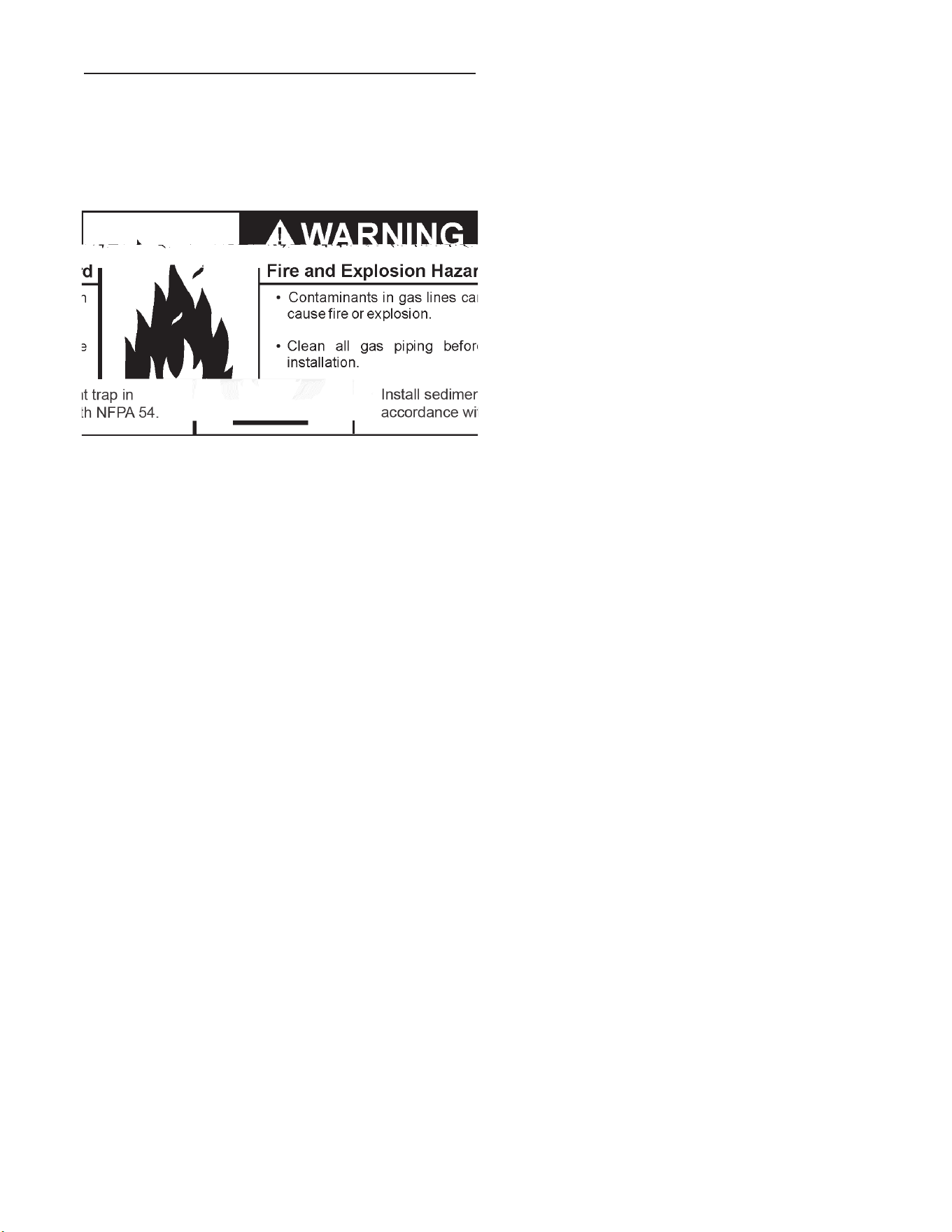
SEDIMENT TRAPS
Asedimenttrapshallbeinstalledasclosetotheinletofthewater
heateraspracticalatthetimeof water heater installation.The
sediment trap shall be either atee fitting with a capped nipple
inthe bottom outlet orother device recognized as an effective
sediment trap. If a tee fitting is used, it shall be installed in
conformance with one of the methods of installation shown in
theFigures15and16.
Contaminantsinthegaslinesmaycauseimproperoperationof
thegascontrolvalvethatmayre sultinf ireorexplo si on.Before
attachingthegaslinebesurethatallgaspipeiscleanonthe
in s i de.Tot rapa ny dir torf o r eignmate r i ali ntheg ass upplylin e,
asedimenttrapmustbeincorporatedinthepiping.Thesediment
trapmustbereadilyaccessible.Installinaccordancewiththe
“GasPiping”section.RefertothecurrenteditionoftheNational
FuelGasCode,ANSIZ223.1/NFPA54ortheNaturalGasand
PropaneInstallationCodeCAN/CSAB149.1.
18
FLAMMABLE
WARNING:
If you do not follow these instructions exactly, a
fire or explosion may result causing property damage, personal
injury or loss of life.
BEFORE LIGHTING: ENTIRE SYSTEM MUST BE FILLED WITH WATER AND AIR PURGED FROM ALL LINES
A.
C.
D.
WHAT TO DO IF YOU SMELL GAS
Do not try to light any appliance.
Do not touch any electric switch; do not use any
phone in your building.
Immediately call your gas supplier from a neighbor's
phone. Follow the gas supplier's instructions.
If you cannot reach your gas supplier, call the fire
department.
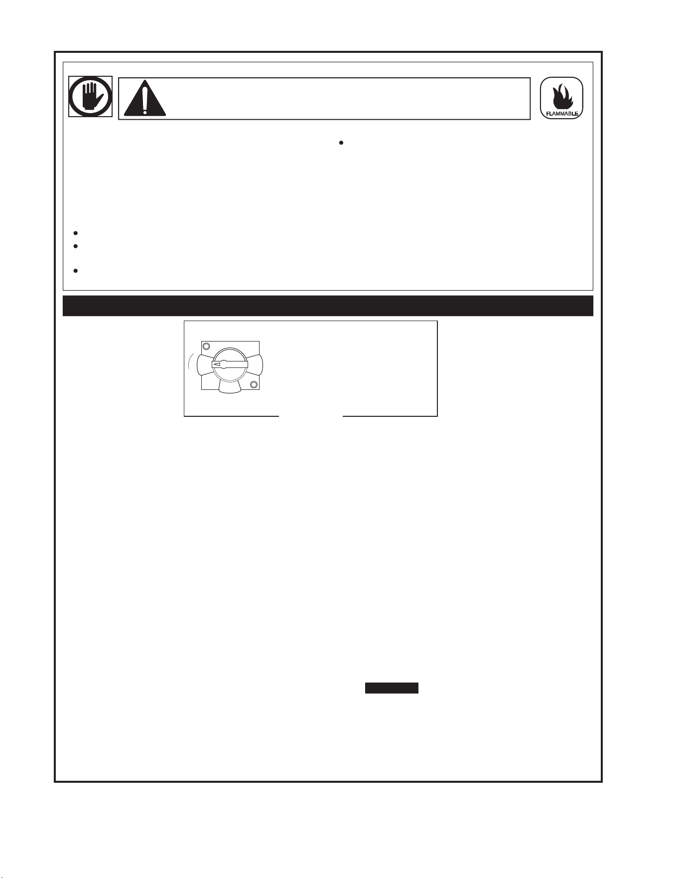
LIGHTING INSTRUCTIONS
TOP KNOB
FIGURE 'A'
"OFF" POSITION
OFF
ON
PILOT
19
START UP CONDITIONS
DRAFT HOOD OPERATION
Check draft hood operation by performing a worst case
depressurization of the building. With all doors and windows
closed, and with all air handling equipment and exhaust fans
operating such as furnaces, clothes dryers, range hoods and
bathroomfans,amatchameshouldstillbedrawnintothedraft
hoodofthewaterheaterwithitsburnerring.Iftheameisnot
drawn toward the draft hood, shut off water heater and make
necessaryairsupplychangestocorrect.
CONDENSATION
Whenever the water heater is filled with cold water, some
condensatewillformwhiletheburnerison.Awaterheatermay
Shortrepeatedheatingcyclescausedbysmallhotwaterusescan
cause temperatures at the point of use to exceed the thermostat
settingby up to 30°F(16.7°C). If you experiencethis type of use
you should consider using lower temperature settings to reduce
scaldhazards.
Any water heater’s intended purpose is to heat water. Hot water
isneededforcleansing,cleaning,andsanitizing(bodies,dishes,
clothing). Untempered hot water can present a scald hazard.
Dependingonthetimeelement,andthepeopleinvolved(adults,
children, elderly, inrm, etc.) scalding may occur at different
temperatures.
HOTTERWATERCANSCALD:Waterheatersareintendedtoproduce
hot water. Waterheated to a temperature which will satisfy space
heating,clothes washing,dishwashing,andothersanitizingneeds
canscaldandpermanently injure you upon contact. Somepeople
aremorelikelytobepermanentlyinjured byhotwaterthanothers.
Theseincludetheelderly,children,theinrm,orphysically/mentally
handicapped.Ifanyoneusinghotwaterinyourhometsintooneof
thesegroupsorifthereisalocalcodeorstatelawrequiringacertain
temperaturewateratthehotwatertap,thenyoumusttakespecial
precautions. In addition to using the lowest possible temperature
settingthatsatisesyourhotwaterneeds,ameanssuchasamixing
valve should be used at the hot water taps used by these people or
atthewaterheater.Mixingvalvesareavailableatplumbingsupplyor
hardwarestores,seeFigure6.Followmanufacturer’sinstructionsfor
installationofthevalves.Beforechangingthefactorysettingonthe
thermostat,readthe“TemperatureRegulation”sectioninthismanual,
seeFigures17and18.
TEMPERATURE REGULATION
FOR YOUR INFORMATION
appeartobeleakingwheninfactthewateriscondensation.This
usuallyhappenswhen:
a.Anewwaterheaterislledwithcoldwaterforthersttime.
b.Bur n i n ggaspr o d u c e s w a t e r vap o r i n w a t e r h e a t e r s,pa r t i c u l a r l y
highefciencymodelswhereuetemperaturesarelower.
c.Largeamountsofhotwaterareusedinashorttimeandthe
rellwaterinthetankisverycold.
Moisturefromtheproductsofcombustioncondenseonthecooler
tank surfaces and form drops of water which may fall onto the
burnerorotherhotsurfacestoproducea“sizzling”or“frying”noise.
Excessive condensation can cause pilot outage due to water
runningdownthefluetubeontothemainburnerandputtingout
the pilot.
Neverallowsmallchildrentouseahotwatertap,ortodrawtheethe=p”

20
CHECKING GAS INPUT
Withthisheaterinoperation,determinewhetheritisreceivingthe
fullratedinput of gas.This may be donebytimingthegasmeter
andmeasuringgaspressurewithagaugeormanometer.Whenthe
heaterisoperatingatfullcapacity(fullgasinput)itshouldconsume
approximately1cubicfootofgasinthetimeshowninTable5.
TABLE 5. INPUT CHECK TIME REQUIRED
TO CONSUME 1 CU. FT. OF GAS
Model Type of Gas
BTU Per
Cu. Ft.
Approx. Time Required To
Consume 1 Cu. Ft. of Gas
BL-80
BL-100
Natural 1050 50.3sec.
Use this formula to “clock” the meter. Be sure that other gas
consumingappliancesarenotoperatingduringthisinterval.
3,600XH=Btu/Hr
T
T=Timeinsecondsneededtoburnonecubicfootofgas.
H=HeatingvalueofgasinBtu’spercubicfootofgas.
Btu/Hr=Actualheaterinputrate.
Example:
T=50.3seconds/ft
3
H=1,050Btu/ft
3
(naturalgas)
Btu/Hr=?
3,600X1,050=75,100Btu/Hr(22.0kW)
50.3
Comparetheactual input ratetothatgiven on the heater’srating
plate.Intheexample,theBL-100’sfullinputrateshouldbe75,100
Btu/Hrfornaturalgas.
Because of the suddenness and amount of water, condensation
watermaybediagnosedasa“tankleak”.Afterthewaterinthetank
warmsup(a0M
21
PERIODIC MAINTENANCE
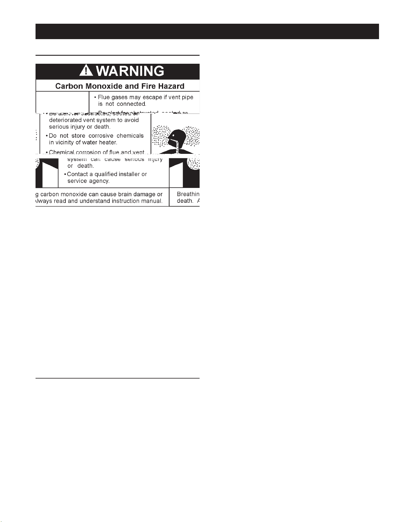
VENTING SYSTEM INSPECTION
Atleastonceayearavisualinspectionshouldbemadeoftheventing
system.Youshouldlookfor:
1. Obstructions which could cause improper venting. The
combustionandventilationairowmustnotbeobstructed.
2. Damage or deterioration which could cause improper venting
orleakageofcombustionproducts.
3. Rustedakesaroundtopofwaterheater.
Be sure the vent piping is properly connected to prevent escape
ofdangerousuegaseswhichcouldcausedeadlyasphyxiation.
Obstructions and deteriorated vent systems may present serious
health risk or asphyxiation.
Chemical vapor corrosion of the ue and vent system may occur
if air for combustion contains certain chemical vapors. Spray can
propellants, cleaning solvents, refrigerator and air conditioner
refrigerants,swimmingpoolchemicals,calciumandsodiumchloride,
waxes,bleachandprocesschemicalsaretypicalcompoundswhich
arepotentiallycorrosive.
Ifafterinspectionofventsystemyoufoundsootingordeterioration,
somethingiswrong.Callthelocalgasutilitytocorrectproblemand
cleanorreplacetheueandventingbeforeresumingoperationof
water heater.
BURNER INSPECTION
Flood damage to a water heater may not be readily visible or
immediatelydetectable.However,overa period oftimeaooded
water heater will create dangerous conditions which can cause
DEATH, SERIOUS BODILY INJURY, OR PROPERTY DAMAGE.
Contactaqualiedinstallerorservicetechniciantoreplaceaooded
waterheater.Donotattempttorepairtheunit!Itmustbereplaced!
Atleastonceayearavisualinspectionshouldbemadeofthemain
burnerandpilotburner,seeFigure19.Inspectburneramesthrough
viewport.Flamesshouldbeverysmallwithabluehazeandsmall
amountsofyellowororangeattheedges.Afterseveralminutesof
operationtheburnerscreenmayglowred.
You should ]
22
WhencheckingtheTemperature-PressureReliefValveoperation,
makesurethat(1)nooneisinfrontoforaroundtheoutletofthe
Temperature-PressureReliefValvedischargeline,and(2)thatthe
waterdischargewillnotcauseanypropertydamage,asthewater
maybeextremelyhot.Usecarewhenoperatingvalveasthevalve
maybehot.
Tocheckthereliefvalve,lifttheleverattheendofvalveseveraltimes,
seeFigure21.Thevalveshouldseatproperlyandoperatefreely.
Ifaftermanuallyoperatingthevalve,itfailstocompletelyresetand
continuesto release water,immediately close thecoldwaterinlet
to the water heaterand drain thewater heater, see DrainingAnd
Flushingonpage24.ReplacetheTemperature-PressureReliefValve
with a properly rated/sized new one, see Temperature-Pressure
ReliefValveonpage11forinstructionsonreplacement.
DISCHARGE PIPE
TEMPERATURE-PRESSURE
RELIEF VALVE
FIGURE 21.
IftheTemperature-PressureReliefValveonthewaterheaterweeps
ordischargesperiodically,thismaybeduetothermalexpansion.
NOTE:Excessivewaterpressureisthemostcommoncauseof
Temperature-Pressure Relief Valve leakage. Excessive water
systempressure is most oftencaused by “thermal expansion”
ina“closedsystem.”SeeClosedWaterSystemsandThermal
Expansiononpage11.TheTemperature-PressureReliefValve
isnotintendedfortheconstantreliefofthermalexpansion.
Temperature-Pressure Relief Valve leakage due to pressure
build up in a closed system that does not have a thermal
expansion tank installed is not covered under the limited
warranty. Thermal expansion tanks must be installed on all
closedwatersystems.
DO NOT PLUG THE TEMPERATURE-PRESSURE RELIEF
VALVE OPENING. THIS CAN CAUSE PROPERTY DAMAGE,
SERIOUS INJURY OR DEATH.
Explosion Hazard
Temperature-Pressure Relief Valve
must comply with ANSI Z21.22-
CSA 4.4 and ASME code.
Properly sized temperature-
pressure relief valve must be
installed in opening provided.
Can result in overheating and
excessive tank pressure.
Can cause serious injury or death.
RECOMMENDED PROCEDURE FOR PERIODIC
REMOVAL OF LIME DEPOSITS FROM TANK TYPE
COMMERCIAL WATER HEATERS
Theamountofcalciumcarbonate(lime)releasedfromwateris
indirectproportiontowatertemperatureandusage,seechart.
Thehigherthewatertemperatureorwaterusage,themorelime
depositsaredroppedoutofthewater.Thisisthelimescalewhich
formsinpipes,heatersandoncookingutensils.
INSTALLEDINSUITABLEAREA:Toinsuresufficientventilation
and combustion air supply, proper clearances from the water
heater must be maintained. See Facts to ConsiderAboutThe
Location section. Combustible materials such as clothing,
cleaningmaterials,orflammableliquids,etc.must
23
Limeaccumulationnotonly reduces the life of the equipment but
alsoreducesefciencyoftheheaterandincreasesfuelconsumption.
The usage of water softening equipment greatly reduces the
hardness of the water. However, this equipment does not always
removeallofthehardness(lime).Forthisreasonitisrecommended
thataregularschedulefordelimingbemaintained.
Thetimebetweencleaningwillvaryfromweekstomonthsdepending
uponwaterconditionsandusage.
Thedepthoflimebuildupshouldbemeasuredperiodically.Heaters
equipped with cleanouts will have about 2” of lime buildup when
theleveloflimehasreachedthebottomofthecleanoutopening.A
schedulefordelimingshouldthenbesetup,basedontheamount
oftimeitwouldtakefora1”buildupoflime.Itisrecommendedthat
thewaterheaterinitiallybeinspectedafter6months.
Example1:
Initial inspection after 6 months shows 1/2” of lime accumulation.
Therefore,theheatershouldbedelimedonceayear.
Example2:
Initialinspectionafter6monthsshows2”oflimeaccumulation.
Therefore,theheatershouldbedelimedevery3months.
FIGURE 22.
DELIMING SOLVENTS
UN•LIME is recommended for deliming. UN•LIME is a patented
foodgradeacidwhichissafetohandleanddoesnotcreatethe
harmfulfumeswhichareassociatedwithotherproducts.
UN•LIMEmaybeobtainedfromyourdealer,distributororwater
heatermanufacturer.OrderPartNumber9005416105,1gallon,
packed 4 gallons per case or Part Number 9005417105, 5
galloncontainer.
NOTE:Un•LimeisnotavailableforuseinCanada.
Hydrochloric base acids are not recommended for use on glass
lined tanks.
Observehandlinginstructionsonlabelofproductbeingused.
TANK CLEANOUT PROCEDURE
Thefollowingpracticeswillensurelongerlifeandenabletheunitto
operateatitsdesignedefciency:
1. Onceamonththeheatershouldbeushed.Openthedrainvalve
andallowtwogallonsofwatertodrainfromtheheater.Inletwater
valveshouldremainopentomaintainpressureintank.
2. Acleanoutopeningisprovidedforperiodiccleaningofthetank.
Gasmustbeshutoffandheaterdrainedbeforeopeningcleanout.
Tocleanheaterthroughcleanoutopening,proceedasfollows:
1. Drain heater.
24
4. Putcapwithmaleadapterbackonthecontainerandslide3/4”
hoseover endofmaleadapter andfastenin placeusinghose
clampprovided.
DELIME USING FLO-JUG METHOD
5. Slidethehoseclampoverendofhoseandslidehoseoverthe
male adapter in the water heater drain opening and secure in
placeusinghoseclamp.
6. Liftcontainertothe“Pour”Positionbeingcarefultokeepthevent
in the handle above the liquid level and pour the UN•LIME into
the heater.
7. Lowercontainer,youmayhavetoplacethecontaineronitsempty
cartontopreventtheUN•LIMEfromowingbackintothecontainer.
8. LetUN•LIMEremainintheheaterfor5minutesandthenlower
thecontainertothe“Drain”Position.
9. Deliming activity is indicated by foaming on the surface of the
UN•LIME.Ifthereisdelimingactivity,repeatsteps6thru8.
Normally,lime removal will be completed within onehour. Severe
build-upoflimemaytakelongerthananhourtocompletedescaling.
Note:TocheckUN•LIMEforcontinueduse,placesomescaleorwhite
chalkinaglasswithasmallamountofUN•LIME.Ifthematerialis
vigorouslydissolvedbythe UN•LIME, it canbereused;ifnot,the
UN•LIMEshouldbereplaced.
Ifthetemperature-pressurereliefvalveontheapplianceweepsor
dischargesperiodically,thismaybeduetothermalexpansion.You
mayhaveacheckvalveinstalledinthewaterlineorawatermeter
with a check valve. Consult your local water supplier or service
technicianfor further information. Do not plug the temperature-
pressurereliefvalve.
DRAINING AND FLUSHING
It is recommended that the water heater storage tank be
drained and ushed every 6 months to reduce sediment
buildup.Thewaterheatershouldbedrainedifbeingshutdown
during freezing temperatures. See Installation Considerations
inthismanualforthelocationofthewaterheatercomponents
describedbelow.

26
TROUBLESHOOTING GUIDELINES
Theseguidelinesshouldbeutilizedbyaqualiedserviceagent.
Problem Cause Solution
27
WATER PIPING DIAGRAMS
October 2009 | Printed in U.S.A. | © A. O. Smith For Technical Information and Automated Fax Service, call 800-527-1953 or visit www.hotwater.com. AOSCG61130 | PAGE 1 of 1
A. O. Smith Corporation reserves the right to make product changes or improvements without prior notice.
NOTES:
1. Preferred piping diagram.
2. The temperature and pressure relief valve setting shall not exceed pressure rating of any component in the system.
3. Service valves are shown for servicing unit. However, local codes shall govern their usage.
4. The Tank Temperature Control should be wired to and control the pump between the water heater(s) and the storage tank(s).
5. The water heater’s operating thermostat should be set 5 degrees F higher than the Tank Temperature Control.
SINGLE FLUE - (1 UNIT)
LEGEND
TEMPERATURE & PRESSURE
RELIEF VALVE
PRESSURE RELIEF VALVE
CIRCULATING PUMP
TANK TEMPERATURE CONTROL
DRAIN
FULL PORT BALL VALV
E
TEMPERATURE GAGE
WATER FLOW SWITCH
CHECK VALVE
WARNING: THIS DRAWING SHOWS SUGGESTED
PIPING CONFIGURATION AND OTHER DEVICES;
CHECK WITH LOCAL CODES AND ORDINANCES
FOR ADDITIONAL REQUIREMENTS.

28
October 2009 | Printed in U.S.A. | © A. O. Smith For Technical Information and Automated Fax Service, call 800-527-1953 or visit ww w.hotwater.com. AOSCG61140 | PAGE 1 of 1
A. O. Smith Corporation reserves the right to make product changes or improvements without prior notice.
NOTES:
1. Preferred piping diagram.
2. The temperature and pressure relief valve setting shall not exceed pressure rating of any component in the system.
3. Service valves are shown for servicing unit. However, local codes shall govern their usage.
4. The Tank Temperature Control should be wired to and control the pump between the water heater(s) and the storage tank(s).
5. The water heater ’s operating thermostat should be set 5 degrees F higher than the Tank Temperature Control.
SINGLE FLUE - (1 UNIT) WITH VERTICAL STORAGE TANK

29
October 2009 | Printed in U.S.A. | © A. O. Smith For Technical Information and Automated Fax Service, call 800-527-1953 or visit ww w.hotwater.com. AOSCG61150 | PAGE 1 of 1
A. O. Smith Corporation reserves the right to make product changes or improvements without prior notice.
NOTES:
1. Preferred piping diagram.
2. The temperature and pressure relief valve setting shall not exceed pressure rating of any component in the system.
3. Service valves are shown for servicing unit. However, local codes shall govern their usage.
4. The Tank Temperature Control should be wired to and control the pump between the water heater(s) and the storage tank(s).
5. The water heater ’s operating thermostat should be set 5 degrees F higher than the Tank Temperature Control.
SINGLE FLUE - (1 UNIT) WITH HORIZONTAL STORAGE TANK

30
October 2009 | Printed in U.S.A. | © A. O. Smith For Technical Information and Automated Fax Service, call 800-527-1953 or visit www.hotwater.com. AOSCG61160 | PAGE 1 of 1
A. O. Smith Corporation reserves the right to make product changes or improvements without prior notice.
NOTES:
1. Preferred piping diagram.
2. The temperature and pressure relief valve setting shall not exceed pressure rating of any component in the system.
3. Service valves are shown for servicing unit. However, local codes shall govern their usage.
4. The Tank Temperature Control should be wired to and control the pump between the water heater(s) and the storage tank(s).
5. The water heater’s operating thermostat should be set 5 degrees F higher than the Tank Temperature Control.
SINGLE FLUE - (1 UNIT) WITH MIXING VALVE TWO TEMPERATURE
31
October 2009 | Printed in U.S.A. | © A. O. Smith For Technical Information and Automated Fax Service, call 800-527-1953 or visit ww w.hotwater.com. AOSCG61170 | PAGE 1 of 1
A. O. Smith Corporation reserves the right to make product changes or improvements without prior notice.
NOTES:
1. Preferred piping diagram.
2. The temperature and pressure relief valve setting shall not exceed pressure rating of any component in the system.
3. Service valves are shown for servicing unit. However, local codes shall govern their usage.
4. The Tank Temperature Control should be wired to and control the pump between the water heater(s) and the storage tank(s).
5. The water heater ’s operating thermostat should be set 5 degrees F higher than the Tank Temperature Control.
SINGLE FLUE - (2 UNITS)
LEGEND
TEMPERATURE & PRESSURE
RELIEF VALVE
PRESSURE RELIEF VALVE
CIRCULATING PUMP
TANK TEMPERATURE CONTROL
DRAIN
FULL PORT BALL VALV
E
TEMPERATURE GAGE
WATER FLOW SWITCH
CHECK VALVE
WARNING: THIS DRAWING SHOWS SUGGESTED
PIPING CONFIGURATION AND OTHER DEVICES;
CHECK WITH LOCAL CODES AND ORDINANCES
FOR ADDITIONAL REQUIREMENTS.
32
SINGLE FLUE
TEMPERATURE & PRESSURE
RELIEF VALVE
PRESSURE RELIEF VALVE
CIRCULATING PUMP
TANK TEMPERATURE CONTROL
DRAIN
FULL PORT BALL VALV
E
TEMPERATURE GAGE
WATER FLOW SWITCH
CHECK VALVE
WARNING: THIS DRAWING SHOWS SUGGESTED
PIPING CONFIGURATION AND OTHER DEVICES;
CHECK WITH LOCAL CODES AND ORDINANCES
FOR ADDITIONAL REQUIREMENTS.

33
NOTES

34
NOTES

35
LIMITED WARRANTY
EFFECTIVE
For 3 Years, in t he event of a tank leak, we will repair or, at our
discret ion, replace t he defe cti ve wat er heat er.
For 1 Year, in t he e vent o f part f ailure, we will repair or, at our
discret ion, replac e t he def ecti ve part .
We warrant this product against def ects in materials or
workmans hip as described in t his document i f installed wit hin
the United Sta tes or Canada and prov ided t he product remains
at its original plac e o f installat ion.
Warranty co v erage begins the date of installation O R the dat e of

36
500 Tennessee Waltz Pkwy., Ashland City, TN 37015
TechnicalSupport:800-527-1953•Parts:800-433-2545
www.hotwater.com
Copyright©2014A.O.SmithCorporation,Allrightsreserved.