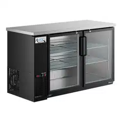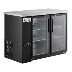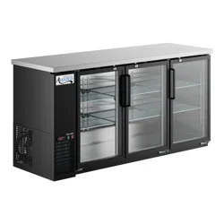
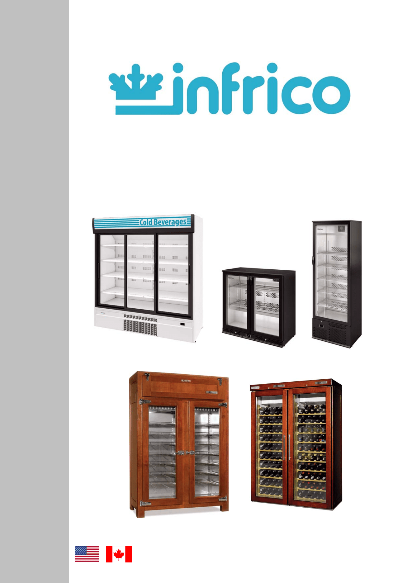
BACK-BAR - MERCHANDISER
REFRIGERATORS - WINE CELLARS
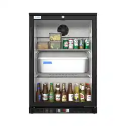
RETRO REFRIGERATORS
Service & Installation Manual
2
Revision: 03 Ref.: MANU_ERV, ERC, EVV 07/17/2014
CTETS
1 GENERAL INFORMATION.................................................................................................3
2 SAFETY PRECAUTIONS...................................................................................................3
3 SERIAL DATA PLATE .......................................................................................................3
4 RECEIVING AND INSPECTING THE EQUIPMENT...........................................................4
5 INSTALLATION..................................................................................................................4
5.1 Location.......................................................................................................................4
5.2 Uncrating.....................................................................................................................4
5.3 Ventilation ...................................................................................................................5
5.4 Leveling.......................................................................................................................5
5.5 Sealing Case to Floor..................................................................................................5
5.6 Initial cleaning procedure.............................................................................................5
6 ELECTRICAL INSTRUCTIONS..........................................................................................6
7 STARTUP PROCEDURE ...................................................................................................6
7.1 Digital temperature controller (Carel)...........................................................................6
7.2 Start-up .......................................................................................................................8
8 OPERATION.......................................................................................................................8
8.1 Temperature control adjustment..................................................................................8
8.2 Defrost control.............................................................................................................9
8.3 Adjusting operation parameters...................................................................................9
8.4 Digital temperature controller (Dixell).........................................................................11
8.5 Loading product.........................................................................................................12
9 ACCESSORIES................................................................................................................12
9.1 Shelving ....................................................................................................................12
10 MAINTENANCE, CARE AND CLEANING........................................................................13
10.1 Cleaning procedure ...................................................................................................13
10.2 Parts and Service......................................................................................................14
11 TROUBLE SHOOTING CHART .......................................................................................15
12 WARRANTY.....................................................................................................................17
12.1 Two year parts & Labor warranty...............................................................................17
12.2 Warranty coverage ....................................................................................................17
12.3 Additional four year compressor part warranty...........................................................18
12.4 Warranty conditions for the supplied products ...........................................................18
12.5 Exclusions from and conditions to warranty coverage ...............................................19
3
Revision: 03 Ref.: MANU_ERV, ERC, EVV 07/17/2014
Congratulations on your purchase. This refrigerator has been manufactured under strict quality controls and meets the
high standards set by Infrico. Before shipping, each individual cabinet has been tested in order to assure a quality product.
Furthermore, it has been produced with recyclable materials using an environmentally friendly process, making an active
contribution to the preservation of our environment.
To get to know all the benefits of your new equipment, please read this instruction manual carefully before installing.
WARNING! Use this unit only for its intended purpose as described in this manual.
When using electrical appliances, basic safety precautions should be followed, including the following:
• This refrigerator must be properly installed and located in accordance with this manual before it is used.
• Do not allow children to climb, stand or hang on the shelves in the refrigerator. They could damage the refrigerator and
seriously injure themselves.
• Do not touch the cold surfaces in freezer compartments when hands are damp or wet. Skin may stick to these extremely cold
surfaces.
• Do not store or use flammable products near the refrigerator.
• Unplug the refrigerator before cleaning and making repairs.
NOTE: We strongly recommend that any servicing be performed by a qualified technician.
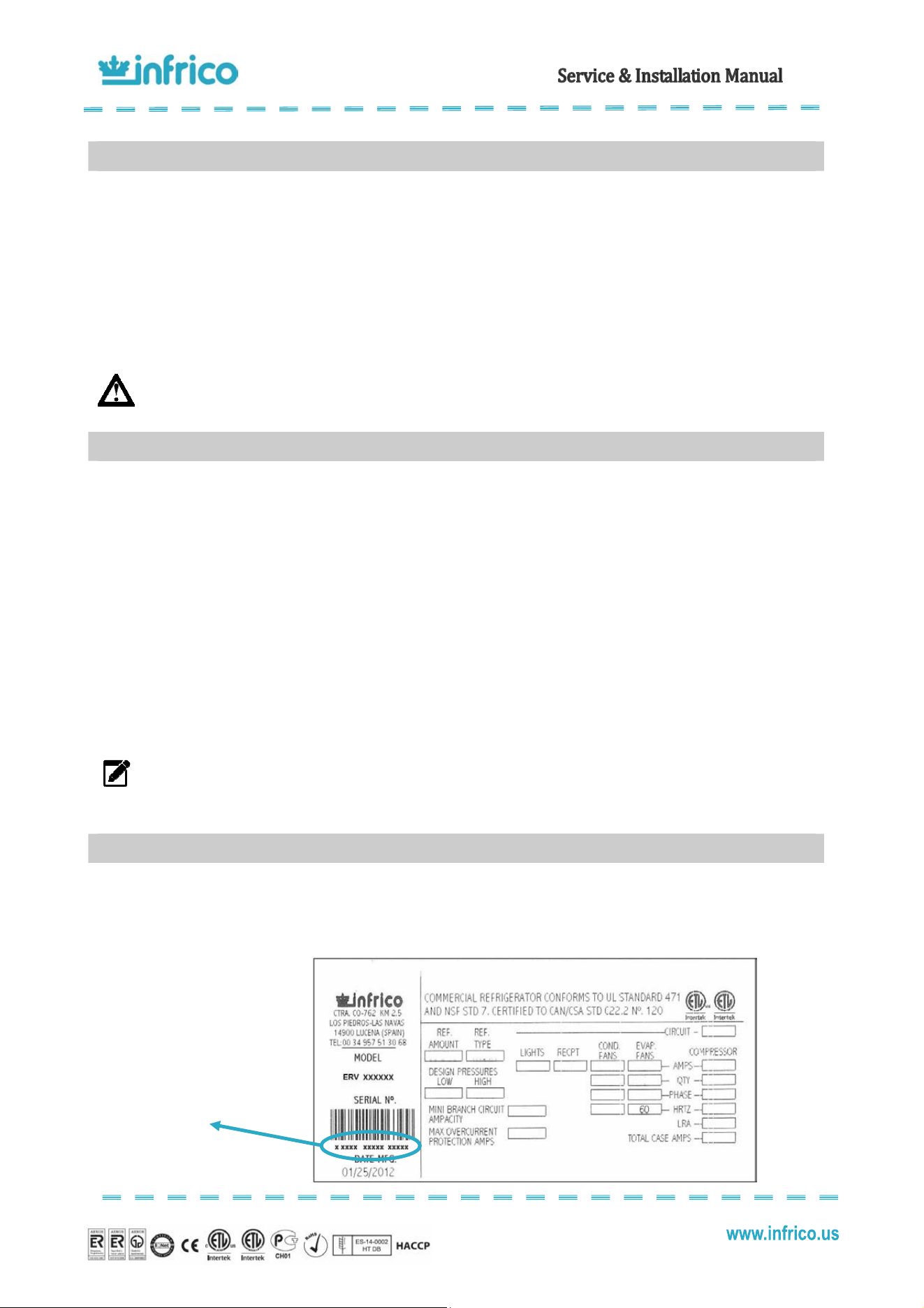
The serial data plate is a permanently affixed label which has important electrical and refrigeration data about your
product, as well as the model and serial number. This label is located in the interior compartment on all standard models.
Serial Number
1
GENERAL INFORMATION
2
SAFETY PRECAUTIONS
3
SERIAL DATA PLATE
4
Revision: 03 Ref.: MANU_ERV, ERC, EVV 07/17/2014
• All Infrico products are factory tested for performance and are free from defects when shipped.
• When your equipment arrives, you should carefully inspect the unit for damage during delivery.
• If damage is detected, you should save all the crating material and make note on the carrier's bill of lading describing the
damage. A freight claim should be filled immediately.
• If damage is subsequently noted during or immediately after installation, contact our customer care service.
NOTE: Infrico is not responsible for damage incurred during shipment.
This unit is intended for indoor use only.
Be sure the location chosen for your unit must be able to provide good air circulation for most efficient refrigeration.
Avoid locations near heat sources such as stoves, ovens, fryers, and also direct sunlight where temperatures can
reach extreme values. Besides, do not select a location in an area where temperatures may drop below 55ºF or increase more
than 90ºF.
You should allow enough clearance between the unit and the side walls in order to make use of the stay open feature
of doors at 120º. The doors must be able to open a minimum of 90º in order to make use of the maximum clear door width.
Furthermore, the floor at the final location must be strong enough to support the total weight of the cabinet plus the
maximum product load. Also, it must be level and free of vibration. Reinforce the floor if necessary.
Back-Bar and Merchandiser ERC 110 are shipped on a wooden pallet in stretch wrapped material and wood crate.
First remove the plastic cover and then unscrew the wooden frame.
Merchandiser ERC 180 is shipped on a wooden pallet in stretch wrapped material and a wood frame. First remove the
plastic cover and then remove the screws on the wooden frame.
All packaging materials used are environmentally friendly and may be recycled or reused. Actively contribute to the
protection of the environment by insisting on packaging recovery and removal methods that are environmentally friendly.
NOTE: Infrico does not recommend laying the unit down on its front, side or back. However, you must be certain
to allow the unit to remain in an upright position afterwards for at least 24 hours before plugging it in so that the
compressor oil and refrigerant may settle.
4
RECEIVING AND INSPECTING THE EQUIPMENT
5
INSTALLATION
5.1
Location
5.2
Uncrating
5
Revision: 03 Ref.: MANU_ERV, ERC, EVV 07/17/2014
To assure maximum operating efficiency, the equipment should be located where a continuous air supply can circulate
around the cabinet. To maintain a proper air flow, a minimum of 30" on the front of the unit must be provided.
Restricting the air supply will generate an excessive heat load on the condensing unit and adversely affect its operating
efficiency. Do not at any time obstruct the grill area in the front of the cabinet in any way.
NOTE: Any restriction of the proper air flow, total or partial, will avoid the warranty on the unit.
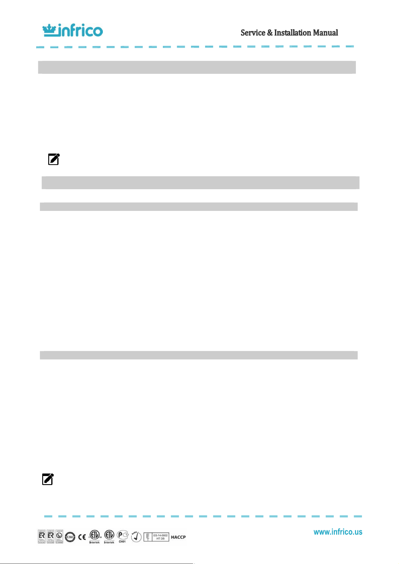
Its extremely important that the cabinet is perfectly level for proper operation so that the drain pan will drain properly,
the doors will line up with the frames and the unit will not be subject to undue strain.
We install feet adjustable from factory. You can adjust these feet as you wish
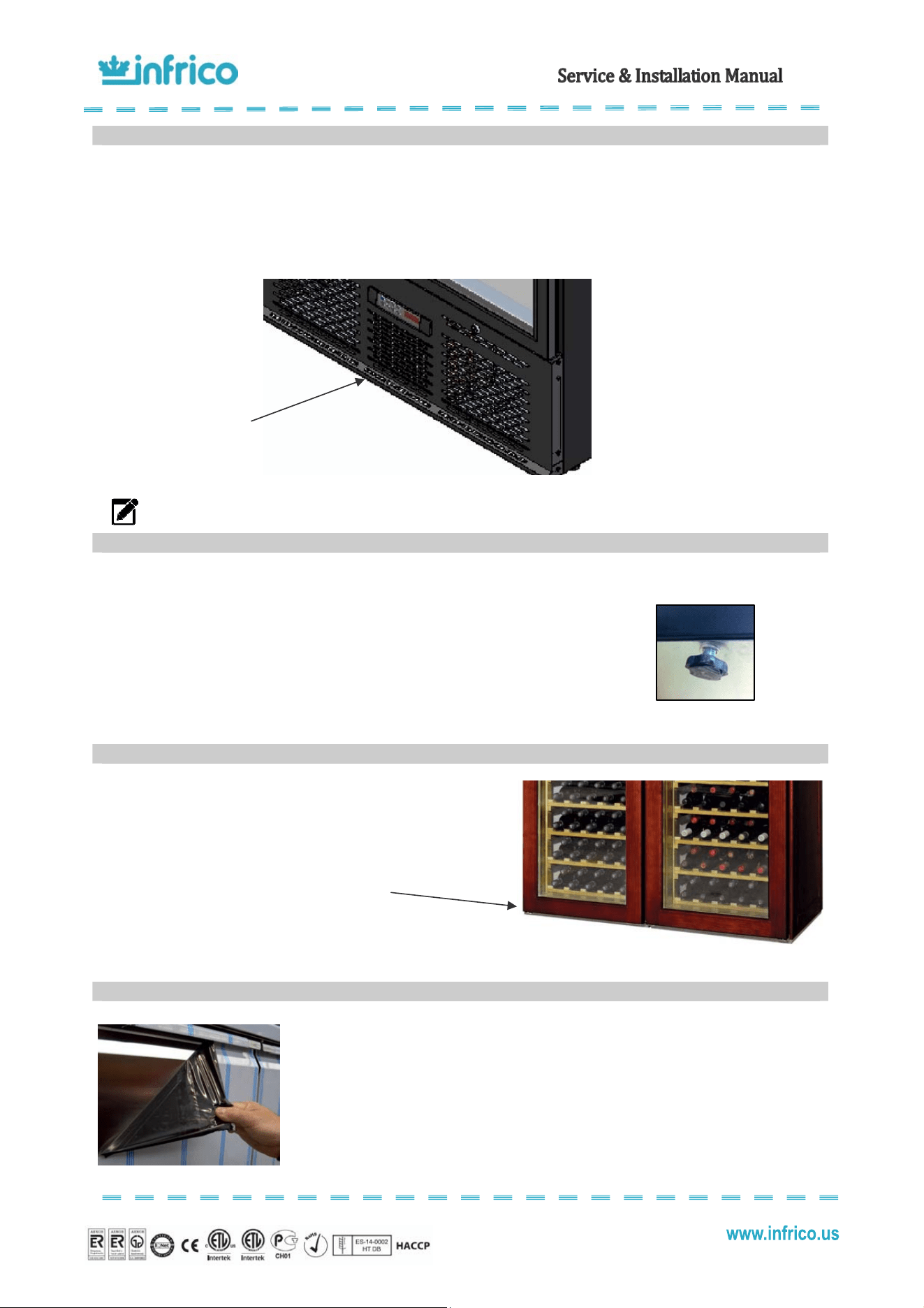
To maintain NSF Sanitation listing cases must sealed to the
floor.
Use NSF sealant such as silicone or equivalent cove
mouldings or tiles are acceptable.
Do not block any louvered holes.
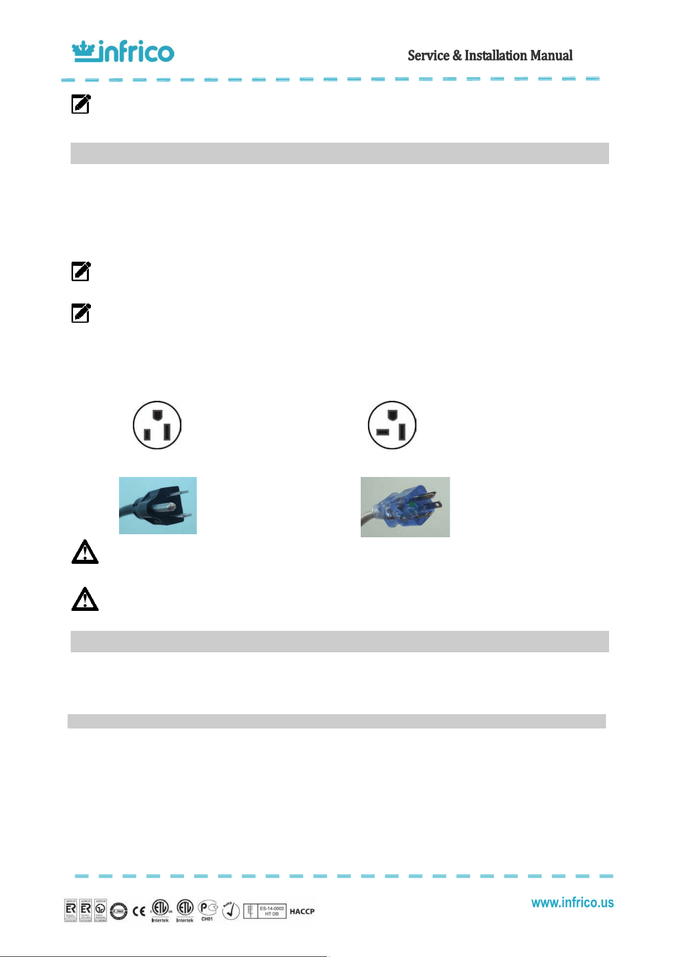
Before starting-up and placing any food inside the cabinet, firstly remove the
protective film and then clean the complete unit thoroughly. If any adhesive remains, eliminate
it with alcohol. Washing with a mild soap and warm water solution is recommended for
cleaning all the stainless steel surfaces of your cabinet. This should be followed by cleaning
with a baking soda solution. Rinse thoroughly with clear water and dry with a clean, soft cloth.
5.3
Ventilation
5.4
Leveling
5.5
Sealing Case to Floor
5.6
Initial cleaning procedure
3
0
" minimum clearance
on the front of the unit
6
Revision: 03 Ref.: MANU_ERV, ERC, EVV 07/17/2014
NOTE: Never use abrasive or harsh cleaners, concentrated detergents, solvents or chemicals when cleaning the
unit.
The supply voltage should be checked before connection to assure that proper voltage for the cabinet wiring is
available. To determine correct unit voltage, please refer to the serial data plate located on an inner wall of the unit. Verify that
this information exactly matches the electrical characteristics at the installation location.
NOTE: Infrico requires that a sole use circuit be dedicated for the unit. Failure to do so voids warranty.
NOTE: The unit is designed to operate with a voltage fluctuation of 5% of the voltage indicated on the cabinet
serial data plate. Burnout of the compressor due to exceeding the high or low voltage limits will automatically
void the factory warranty.
Units are provided with a U.L. approved power cord and plug which is factory installed. Infrico use these types of plugs.
If you do not have the right outlet have a certified electrician install the correct power source:
115 / 60 / 1 NEMA 5-15P
115 / 60 / 1 NEMA 5-20P
WARNING: Any alterations to this cord and plug could cause an electrical hazard and will void the factory
warranty. Furthermore, never use an adapter plug.
WARNING: Infrico will not warranty any units that are connected to an extension cord.
After the cabinet has been installed, levelled, cleaned and electrically connected in accordance with this manual, it is
ready to operate.
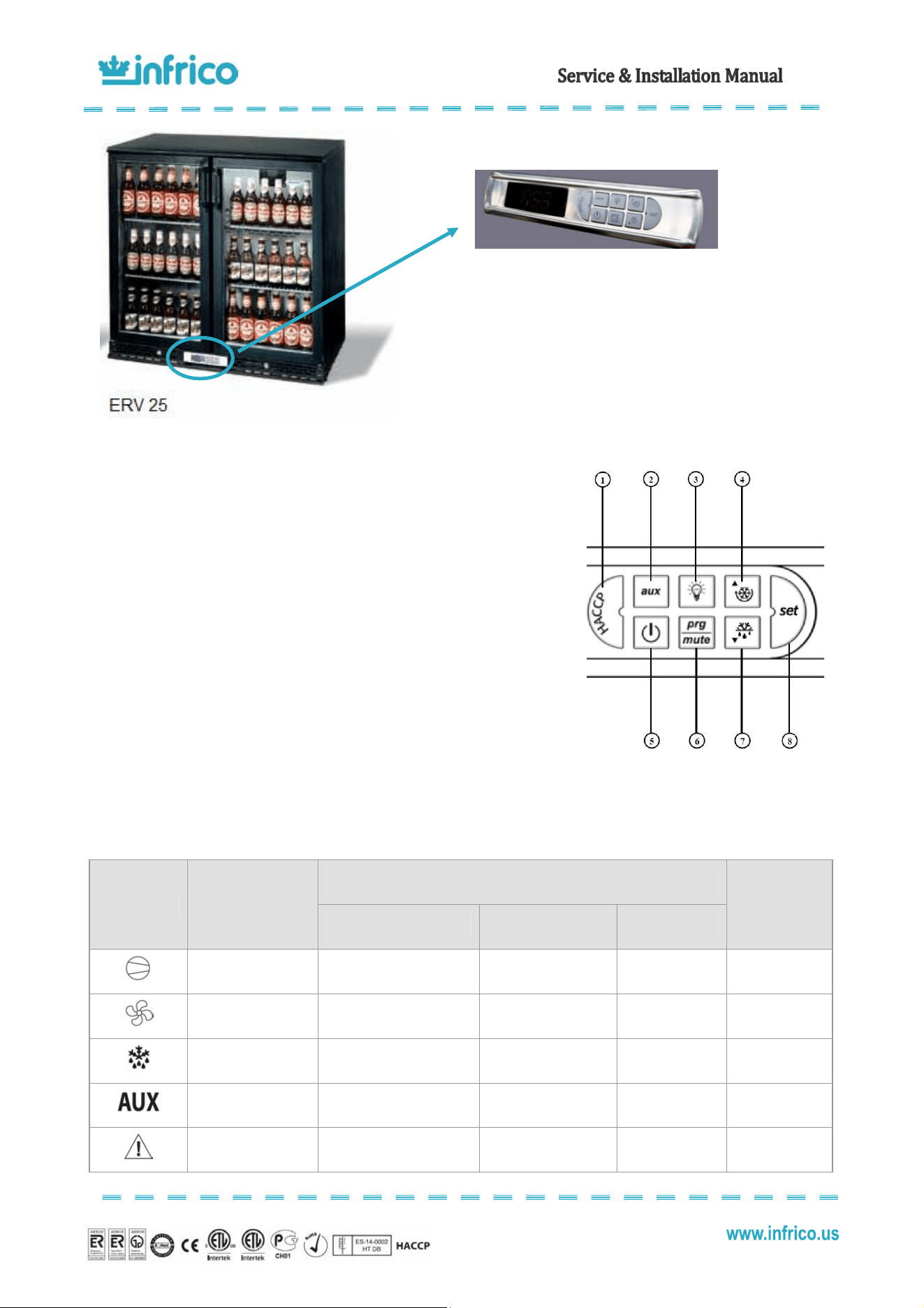
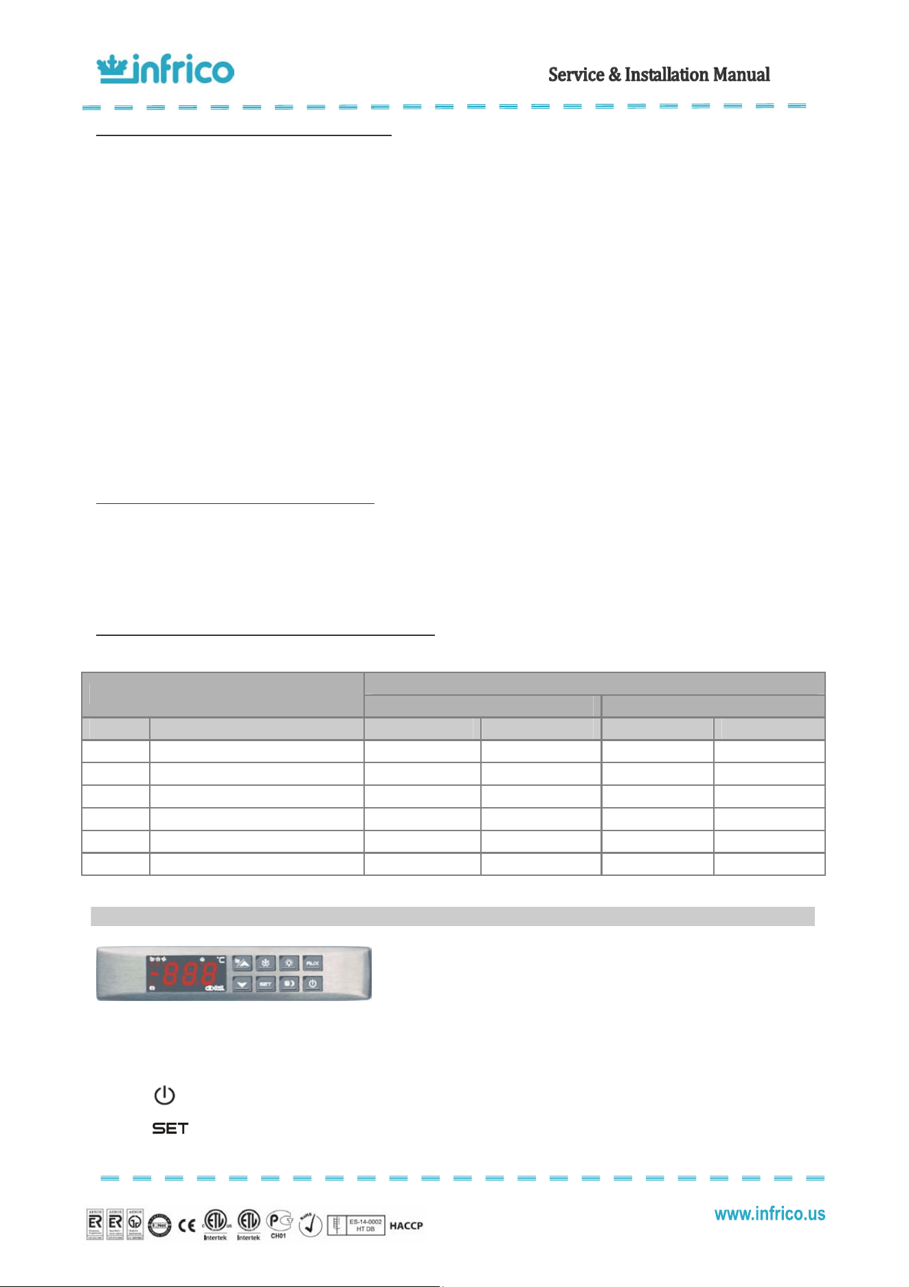
These units are equipped with a digital temperature controller located in the front panel.
This digital controller is fitted with a very powerful display, with 3 digits and decimal point and icons. The keypad
ensures ease of use and reliability, and allows direct access to several operation functions.
6
ELECTRICAL INSTRUCTIONS
7
STARTUP PROCEDURE
7.1
Digital temperature controller (Carel)
7
Revision: 03 Ref.: MANU_ERV, ERC, EVV 07/17/2014
KEYPAD
1. HACCP: Enter the HACCP alarm display menu (optional).
2. AUX: Deactivated in these models.
3. LIGHT: Deactivated in these models.
4. UP / CC: If pressed for more than 5 seconds, activates/deactivates continuous
cycle operation.
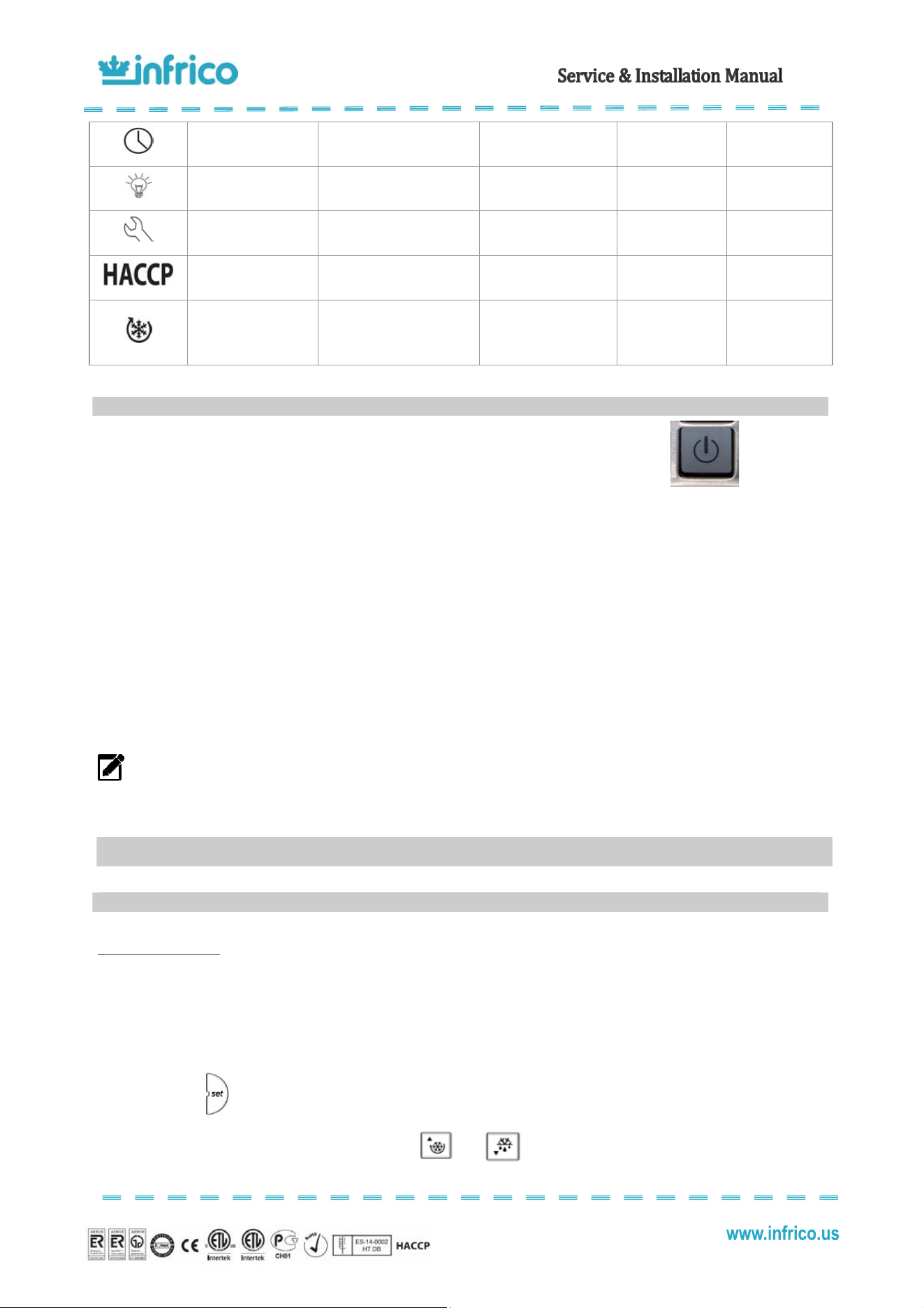
5. ON/OFF: If pressed for more than 5 seconds, it will turn the equipment on/off.
6. PRG/MUTE: In the event of an alarm: this mutes the sound alarm (buzzer) and
deactivates the alarm relay.
7. DOWN / DEF: If pressed for more than 5 seconds, it will turn manual defrosting
on/off provided the evaporator temperature is lower than the final programmed
defrosting temperature.
8. SET: If pressed for more than 1 second, it will display and/or confirm the set point.
DISPLAY AND ICONS
Normal Operation
Icon Function
ON OFF Flashing
Start-up
COMPRESSOR Compressor on Compressor off
Compressor
required
FAN Fan on Fan off Fan required
DEFROST Defrost in operation Defrost not in operation Defrost required
AUX
AUXILIARY Auxiliary output
active
AUXILIARY Auxiliary
output not active
ALARM
Delayed external alarm (before
“A7”)
No alarm present
Alarms in normal
operation
8
Revision: 03 Ref.: MANU_ERV, ERC, EVV 07/17/2014
CLOCK
At least 1 timed defrost has
been configured.
No timed defrost is
present.
ON if real-time
clock is present
LIGHT LIGHT auxiliary output on LIGHT auxiliary output off
ASSISTANCE No malfunction Malfunction
HACCP HACCP functions enabled
HACCP functions not
enabled
HACCP alarm
saved to memory
CONTINUOUS CYCLE
CONTINUOUS CYCLE function
activated
CONTINUOUS CYCLE
function deactivated
CONTINUOUS
CYCLE function
request
Plug the apparatus into an electrical socket.
The digital controller will display "OFF" and alternatively the cabinet temperature.
Connect the start-up ON/OFF button during more than 5 seconds. The cabinet temperature will be displayed and "OFF" will
disappear. The compressor starts up after 1 minute.
The system should run smoothly and quietly in accordance with generally accepted commercial standards. If any
unusual noises are heard, turn the unit off immediately and check for any obstructions of the fans.
All cabinets must be given enough time to reach normal operating temperature before placing any food inside cabinet
or pans (if equipped). Continuous opening and closing of the doors / drawers will hamper the unit's ability to maintain optimum
refrigeration performance.
NOTE: Before loading product, we recommend to run the unit empty during 24 hours. Refrigerated Back-Bar and
Merchandiser are designed to maintain an approximate temperature of 39ºF.
Setting the set point
The set point establishes the high point of the desired cabinet temperature range. This parameter is preset at the
factory and does not have to be adjusted unless the customer chooses to do so.
To display or set the set point, proceed as follows:
1) Press for more than 1 second to display the set point;
2) Increase or decrease the set point using the
and buttons respectively, until reaching the desired
value;
7.2
Start-up
8
OPERATION
8.1
Temperature control adjustment
9
Revision: 03 Ref.: MANU_ERV, ERC, EVV 07/17/2014
3) Press again to confirm the new value.
Refrigerated Back-Bar (ERV) and Merchandiser (ERC)
The thermostat is factory set at 39ºF. The minimum temperature that can be set for the set point is 28ºF.
Re-establishing manual reset alarm
It is possible to re-establish all manual reset alarms by pressing the “PROG/MUTE” and “CONTINUOUS CYCLE”
buttons at the same time for more than 5 seconds.
All these models are equipped with an automatic defrost system which clears the evaporator coil of any accumulated
frost. Frost is accumulated on the evaporator coil during the normal operation. The defrost are time-initiated and temperature-
terminated.
In refrigerators, prep tables and chef bases, defrost system works by switching-off the condensing unit and switching-
on the evaporator fan(s). The defrost cycle occurs automatically every four hours and is indicated by the letters "dEF" displayed
on the screen. The defrost cycle should last until the temperature set for the end of the defrost cycle is reached or for a
maximum of 30 minutes.
Freezer models have a hot gas defrost system. Hot gas defrost system works by routing superheated compressor
discharge gas directly to the evaporator. The defrost cycle occurs automatically every three hours and is indicated by the letters
"dEF" displayed on the screen. The defrost cycle should last until the temperature set for the end of the defrost cycle is reached
or for a maximum of 30 minutes.
At the end of the defrost cycle, the cabinet starts with normal refrigeration operation.
Starting a Manual Defrost Cycle
In case a manual defrost is required, it is possible to activate it by pressing button for 5 seconds.
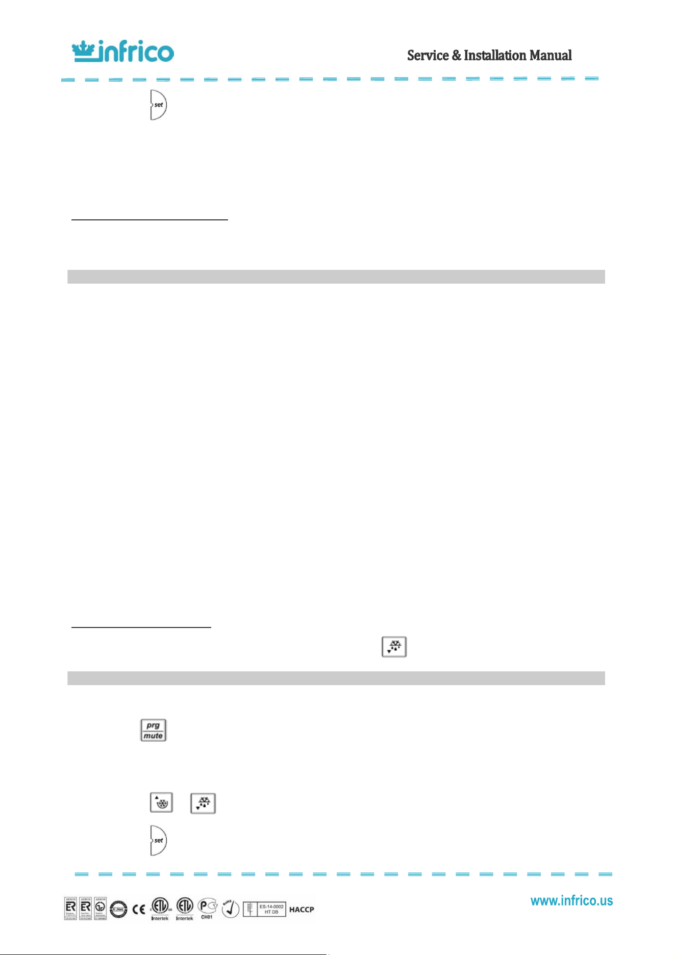
There are some parameters that can be modified by the user. To access the frequent parameters, proceed as follows:
Press for more than 5 seconds (if an alarm is active, the buzzer is muted), the display shows the code of the
first modifiable parameter. Then, follow the next instruction:
1) Press or until reaching the parameter to be modified;
2) Press
to display the associated value;
8.2
Defrost control
8.3
Adjusting operation parameters
10
Revision: 03 Ref.: MANU_ERV, ERC, EVV 07/17/2014
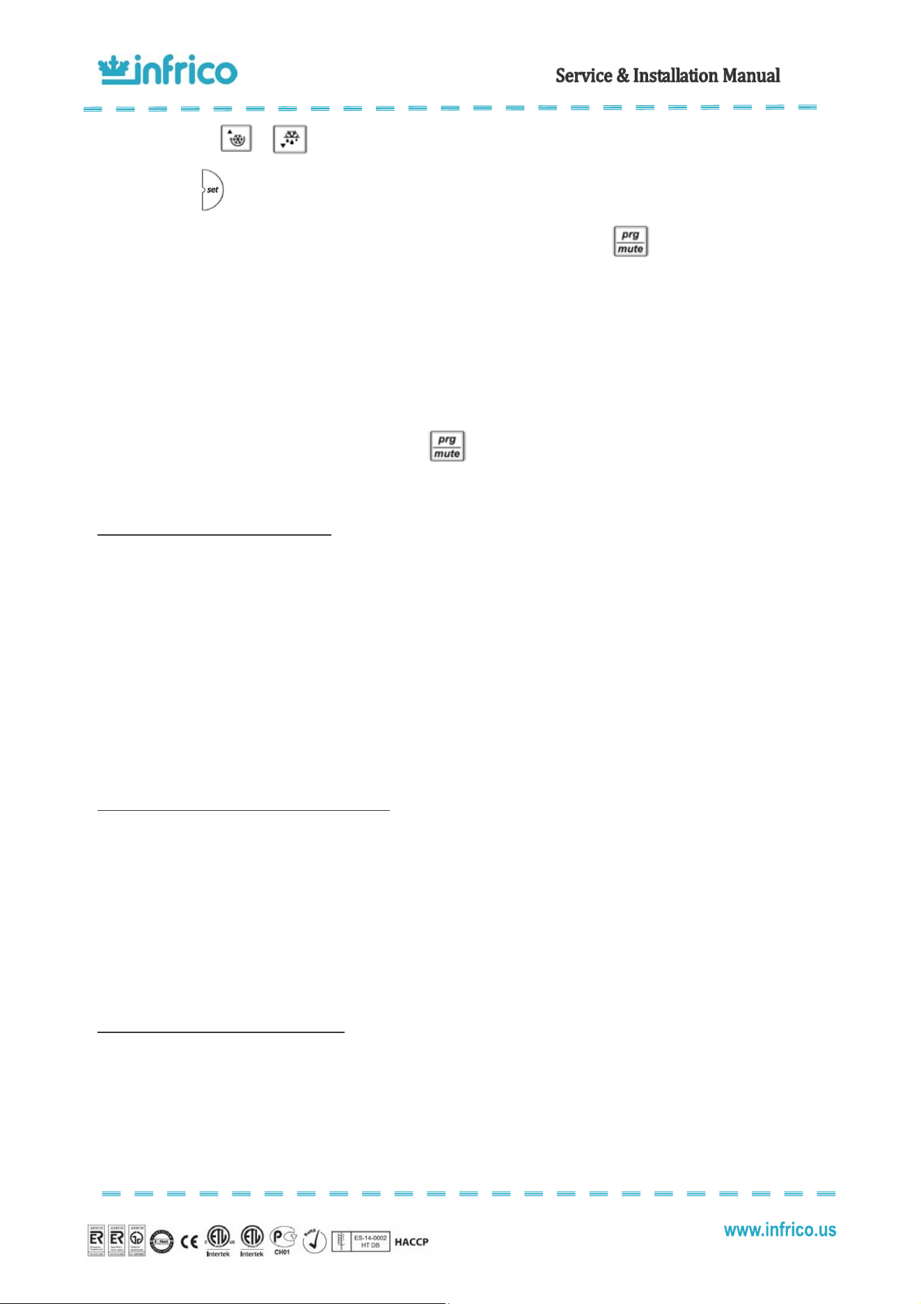
3) Increase or decrease the value with the or buttons respectively, until reaching the desired value;
4) Press to temporarily save the new value and return to the display of the parameter code;
Important: To definitively save the new values of the modified parameters, press for more than 5 seconds, thus
exiting the parameter setting procedure.
All the modifications made to the parameters, temporarily saved in the RAM, can be cancelled and "normal operation"
resumed by not pressing any button for 60 seconds, thus allowing the parameter setting session to expire due to timeout.
Important: if the programming session ends by timeout, the parameters relating to the clock will not be reset, as these
parameters are saved immediately when entered.
If the instrument is switched off before pressing , all the modifications made to the parameters and temporarily
saved will be lost.
Adjusting the Set Point Differential (rd)
This parameter sets the number of degrees the air temp will rise above set point before the refrigeration system will
cycle on. In refrigerators and prep tables models, the set point differential is set at 7.2 which will allow the air temperature to rise
7.2 degrees above set point setting before cycling refrigeration on. In freezers, the set point differential is set at 5.4. This
parameter is preset at the factory and does not have to be adjusted unless the customer chooses to do so.
To set the set point differential, the parameter that should be changed is "rd" according to the previous instructions.
The range of adjustment that we recommend is 3.6ºF / 10.8ºF. Low values guarantee a room temperature that deviates only
slightly from the set point, but involves frequent starts and stops of the compressor.
Adjusting the Thermostat Probe Calibration (/c1)
This parameter is used to correct the temperature measured by the probe, using an offset. The value assigned to this
parameter is in fact added to (positive value) or subtracted from (negative value) the temperature measured by the probe. The
temperature value is corrected by the offset before checking if the reading is out-of range.
To set the thermostat probe calibration, the parameter that should be changed is "/c1. The default value is 0 which
means that there is no offset to the reading of probe 1.
Adjusting the Anti-Short Cycle Delay (c1)
This parameter sets the minimum time (in minutes) between two starts of the compressor, irrespective of the
temperature and the set point. Setting this parameter limits the number of starts per hour.
To set the anti-short cycle delay, the parameter that should be changed is "c1" . The default value is 1minute.
11
Revision: 03 Ref.: MANU_ERV, ERC, EVV 07/17/2014
Adjusting the Interval between Defrost Cycles (dl)
The defrost cycles are performed periodically at an interval equal to the value of "dl" in hours. The interval "dl" starts
being counted from the end of the previous count. The duration of the defrost therefore does not affect then the interval between
defrost cycles. The interval "dl" is cyclical and is also maintained when the controller is OFF. If the interval "dl" expires when the
controller is OFF, when it is started again a defrost will be performed.
If "dl"=0 the defrost is never performed except for when forced from the keypad (manual defrost).
Important: To ensure regular defrosts, the interval between defrost cycles must be greater than the maximum defrost
duration, plus the dripping time and post-dripping time.
Note: during defrost cycles the temperature alarms are disabled.
The parameter is "dl. The default value is 4 hours in refrigerated tables, prep tables and chef bases. In freezer, the
default value is 3 hours.
Adjusting the Maximum Defrost Duration (dP1)
This parameter determines the maximum defrost duration on the evaporator in minutes if defrost by temperature is
selected. If timed defrost has been selected, this represents the actual duration of the defrost selected. The parameter is "dP1" .
The default value is 30 minutes.
Summary of parameters that can be modified by the user
Default settings for:
SUMMARY OF USER / SERVICE PARAMETERS
Back-Bar Merchandiser
LABEL NAME RANGE DEFAULT VALUE RANGE DEFAULT VALUE
St Set Point -32ºF/60,8 ºF 36 -32ºF/60,8 ºF 36
rd Differential
0,2 ºF/36 ºF
7,2
0,2 ºF/36 ºF
7,2
/cl Thermostat Probe Calibration
-36 ºF/36 ºF
0
-36 ºF/36 ºF
0
cl Anti-Short Cycle Delay 0/15 min. 1 0/15 min. 1
dl Interval Between Defrost Cycles 0 h./250 h. 4 0 h./250 h. 4
dP1 Maximum Length of Defrost 1 min./250 min. 30 1 min./250 min. 30
These units are equipped with a digital temperature controller located in the
front panel.
This digital controller is fitted with a very powerful display, with 3 digits and decimal point and icons. The keypad
ensures ease of use and reliability, and allows direct access to several operation functions.
The temperature is set at the factory but local conditions may need slight adjustment.
: This turns the condensing unit and lights off. There is still power to the controller.
: for displaying or modifying the set point. When displaying the maximum and minimum
temperature, these can be deleted by keeping the button pressed for 3 second.
8.4
Digital temperature controller (Dixell)
12
Revision: 03 Ref.: MANU_ERV, ERC, EVV 07/17/2014
This displays the maximum stored temperature; in programming mode and “Function
Menu” mode it is used to look through the parameter codes or increase the value of the variable in use.
This displays the minimum stored temperature; in programming mode and “Function
Menu” mode it is used to look through the parameter codes or decrease the value of the variable in use.
: This turns the light on and off.
Note: while in the OFF status, the light button is active
• Before introducing food into the cabinet, it is advisable to leave it empty while in operation until it reaches the working
temperature. Once this has been reached, you can proceed to load the equipment.
• When introducing food, enough space must be left between the goods to enable air circulation.
• Never allow the goods to prevent doors from closing.
• Do not exceed the maximum weight per shelf of 55 lb.
• Do not obstruct the fan with the load and assure that this never exceeds the maximum load level determined. The load must
therefore always be situated underneath the fan.
• Never put hot food in the cabinet.
• Do not leave food inside the unit when it is going to remain shut down either from a power outage or fault in the equipment.
• If the cabinet is going to remain shut down for prolonged periods, try to leave it unplugged, empty, clean and with door ajar.
• Food or drinks may be well wrapped or enclosed in airtight containers to avoid odours inside the unit.
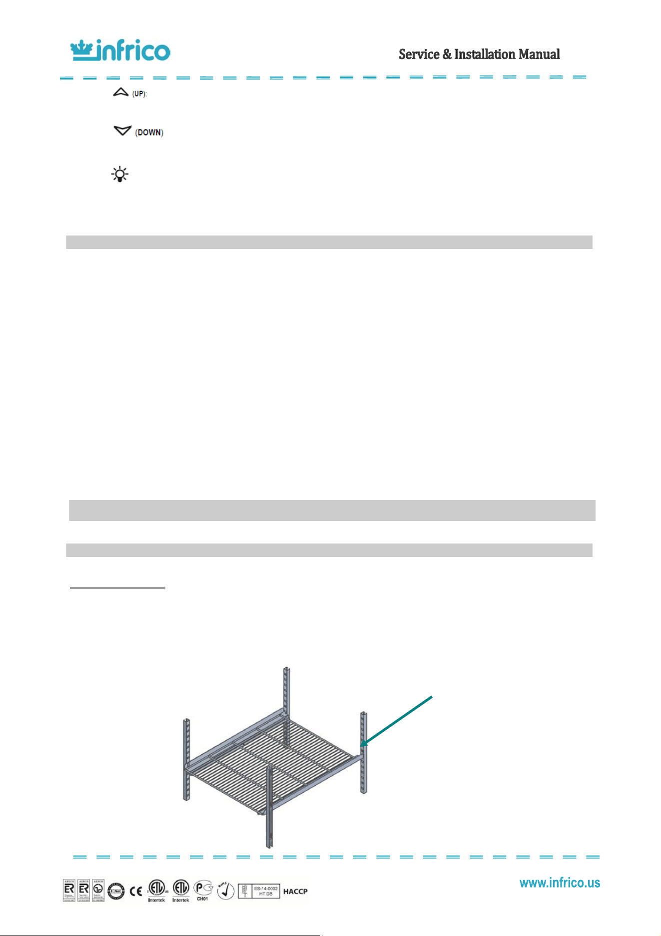
Installation of shelves
Back-Bar are supplied from factory with pilasters, stainless steel rails and stainless steel shelves. Shelf rails are installed by
inserting them into the pilasters at the desired shelf location. Then, place shelves on the rails, making sure they are seated
properly.
8.5
Loading product
9
ACCESSORIES
9.1
Shelving
Insert the
rails
into the
pilasters and place the
shelves on the rails
13
Revision: 03 Ref.: MANU_ERV, ERC, EVV 07/17/2014
Ceaig the cabiet
To clean the cabinet, the following instruction should be followed:
• Disconnect the unit from the power supply and remove all food product from inside.
• Open all doors and allow the cabinet to reach room temperature. Remove all accessories and clean them with a baking soda
or mild soap and warm water solution. Dry all of the accessories completely with a soft clean cloth.
• Once the cabinet has reach room temperature, wash the entire cabinet inside and out with a baking soda or mild soap and
warm water solution. Rinse thoroughly with clear water and dry with a soft clean cloth. Failure to dry all surface completely
may cause water stains. There are also stainless steel cleaners available which can restore and preserve the finish of the
steels protective layer.
• Return all accessories to their initial positions and plug the unit in.
• Early signs of stainless steel breakdown can consist of small pits and cracks. If this has begun, star to apply stainless steel
cleaners in order to restore the passivity of the steel.
• Many product foods have an acidic content which can attack stainless steel, such as mustard, mayonnaise, lemon juice,
tomatoes and other vegetables.
NOTE: Never use steel pads, wire brushes or scrapers to clean the cabinet.
NOTE: Cleaning solutions need to be alkaline based or non-chloride cleaners. Any cleaner containing chlorides
will damage the protective film of the stainless steel.
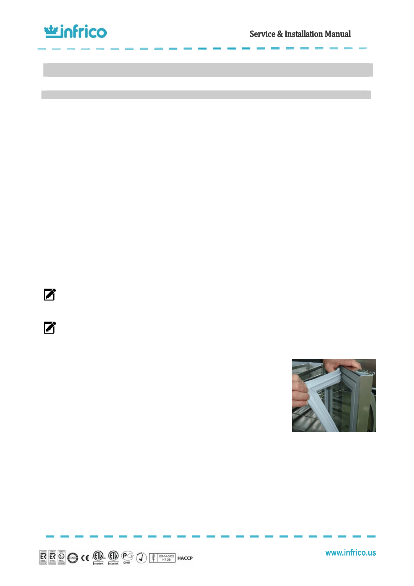
Gasets aiteace
• Gaskets require regular cleaning to keep their elasticity, to maintain proper sealing and to
prevent mildew build up. Gasket cleaning can be done with the use of warm soapy water.
Avoid hard cleaners and sharp tools when cleaning gaskets.
• Gaskets can easily be replaced just pulling out of the grove in the door and new gaskets can
be pressed back into place.
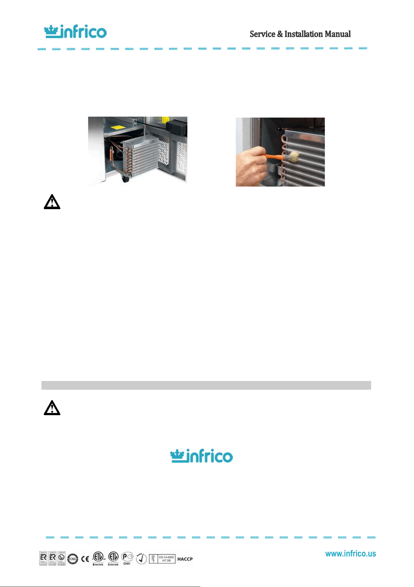
Ceaig the cdeser ci
The condenser coil, which is located directly behind the front panel, must be checked periodically. The frequency of
cleaning depends on the operating environment. Air must be able to freely circulate through the condenser, so the surface of the
condenser must be kept free of dirt and grease for proper system operation. Dirty condensers result in compressor failure and
product loss. If the condenser coil is dirty or blocked, follow this instruction:
• Disconnect the power supply
• Remove the screws on the hinged front panel of the cabinet and open it.
10
MAINTENANCE, CARE AND CLEANING
10.1
Cleaning procedure
14
Revision: 03 Ref.: MANU_ERV, ERC, EVV 07/17/2014
• Slide out the condensing unit, and the condenser is easy accessible.
• Carefully clean dirt from the condenser using a vacuum cleaner of soft brush; never use a wire brush.
• Heavier dust build up may require compressed air to blow through the condenser coil.
• Slide the condensing unit back into position.
• Finally, replace the front panel, tighten all screws and reconnect electrical power supply.
WARNING: Never use water for this cleaning procedure as water can damage the electrical components
located near or at the condenser coil.
DrsHiges aiteace
Over time and with heavy use doors the hinges may become loose. If it is noticed that the door is beginning to sag, it
may become necessary to tighten the screws that mount the hinge brackets to the frame of the unit.
Drai aiteace
Each unit has a drain located inside the unit which removes the condensation from the evaporator coil and evaporates
it at an external condensate pan. If you notice excessive water accumulation on the inside of the unit be sure the drain tube is
connected from the evaporator housing to the condensate evaporator drain pan.
If water is collected underneath the unit you may want to check the condensate evaporator drain tube to be sure it is
still located inside the drain pan.
Be sure all drain lines are free of obstructions, typically food product is found blocking drain lines causing water to back
up and overflow the drain pans.
WARNING: Make sure that the equipment is unplugged before cleaning or repairing it.
If the problem persists after you have carried out the indicated checks, “DO NOT MAKE ANY REPAIRS YOURSELF”.
Contact our Technical Service. Always provide the cabinet model and serial number (located on the data plate, 13 digits)
FOR GENUINE FACTORY PARTS
& AUTHORIZED SERVICE
1-855-340-4637
NOTE: When a replacement part is required, always insist on factory authorized parts only.
10.2
Parts and Service
15
Revision: 03 Ref.: MANU_ERV, ERC, EVV 07/17/2014
Many operating problems are derived from causes that can be easily eliminated without the need to contact the
Technical Department. The following page shows a table with types of problems that may come up, their cause, and how to
resolve them.
PROBLEM POSSIBLE SOLUTION
Compressor will not start-no
hum.
1.- Disconnect switch open.
2.- Blown fuse.
3.- Defective wiring.
4.- Overload protector tripped.
5.- Open control contacts (control may be defective, or unit location may be
too cold).
6.- Defective overload protector.
7.- Low charge of freon-check for leaks.
Compressor will not start-no
hums but cycles on overload.
1.- Low voltage.
2.- Unit wired incorrectly.
3.- Starting capacitor defective.
4.- Starting capacitor seal.
5.- Compressor motor defective.
6.- High head pressure.
7.- Bearing of pistons tight-low oil charge.
Compressors start, but starting
remains in circuit.
1.- Low voltage.
2.- Unit wired incorrectly.
3.- Starting capacitor seal.
4.- Running capacitor defective.
5.- Starting relay defective.
6.- High head pressure.
7.- Bearings of pistons tight-low oil charge.
Compressor starts and runs, but
cycles on overload
1.- Low voltage.
2.- Running capacitor defective.
3.- Overload protector defective.
4.- High head pressure.
5.- Fan motor, pump, etc… , wire to wrong of overload protector.
Compressor tries to start when
thermostat closes but cuts out on
overload, start after several
attempts.
1.- Low voltage.
2.- Start capacitor defective.
3.- Overload protector defective.
4.- High head pressure.
5.- Fan motor, pump, etc… , wire to wrong of overload protector.
11
TROUBLE SHOOTING CHART
16
Revision: 03 Ref.: MANU_ERV, ERC, EVV 07/17/2014
PROBLEM POSSIBLE SOLUTION
Compressor tries to start when
thermostat closes but cuts out on
overload, start after several
attempts.
1.- Low voltage.
2.- Low on oil.
3.- High head pressure.
4.- Starting relay points badly pitted.
5.- Starting capacitor weak.
6.- Air or non-condensable gases in system.
Compressor starts but
immediately cuts out on overload
1.- Starting relay contacts points welded together.
2.- Starting capacitor defective.
3.- Compressor short cycles.
Starting relay burns out.
1.- Low voltage.
2.- High voltage.
3.- Compressors short cycles.
4.- Incorrect running capacitor.
5.- Incorrect relay.
Running capacitors burn out. 1.- Line voltage too high.
Head pressure to high
1.- Unit overcharged.
2.- Air or other non-condensable gases in system.
3.- Clogged condenser (air-cooled)
4.- Defective condenser fan motor.
5.- Unit location too hot.
6.- Restriction in expansion valve, strainer or drier.
7.- Discharge valve partially closed.
8.- Restriction in discharge line.
Head pressure to low
1.- Insufficient refrigerant charge.
2.- Leak in the system.
3.- Cold location.
Compressor short cycles
1.- Control differential set too close.
2.- Refrigerant undercharge, check pressure control.
3.- Refrigerant overcharge.
4.- Discharge valve leaking.
5.- Cutting out on high pressure control, if used.
6.- Cutting out on overload protector because if tight bearings struck piston,
high head pressure or restricted air cooled condenser.
17
Revision: 03 Ref.: MANU_ERV, ERC, EVV 07/17/2014
PROBLEM POSSIBLE SOLUTION
Running cycles too long, or unit
operates continuously
1.- Insufficient refrigerant charge.
2.- Dirty or restricted condenser.
3.- Unit location too hot.
4.- Control contacts stuck.
5.- Air or other non-condensable gases in system.
6.- Expansion valve plugged or defective.
7.- Fixture doors left open too long.
8.- Insufficient, defective or water logged insulation.
9.- Evaporated oil logged.
Noisy unit
1.- Compressor oil charge low.
2.- Fan cable on condenser or evaporator bent causing vibrations.
3.- Bearing on evaporator or condenser motors lose or worn.
4.- Tube rattles.
5.- Lose parts on condensing unit.
6.- Case is not level.
Dear user:
You must receive the warranty certificate duly filled out within a maximum period of 20 days from the purchase date so
that the equipment you have just purchased may benefit from the warranty specified in this document. Otherwise, this warranty
manufactures date.
It is very important that you read the attached documentation carefully so that you have full knowledge of the use and
care applicable to your equipment. This being the case, we are sure that you will be completely satisfied with its operation.
Infrico USA, Corp. (“Infrico”) warrants to the original customer that the Infrico brand equipment sold hereunder, except
for parts and accessories which carry the warranty of a supplier (the “Equipment”) will be free from defects in material and factory
workmanship under normal conditions of use and maintenance for a period of (2) two years from the Date of Installation
(Warranty Commencement Date), but in no event to exceed (27) months from the Date of Shipment. Warranty is Not
Transferable.
If there is a defect in material or factory workmanship covered by this Warranty reported to Infrico during the period the
applicable Warranty is in force and effect, Infrico will repair or replace, at Infrico’s option, that part of the Equipment that has
become defective. Infrico will cover labor cost within (2) two years from the Warranty Commencement date or (27) months from
shipment date, whichever occurs first. Infrico shall bear all labor costs in connection with the installation of these replacement
parts, provided that, the installation is conducted by Infrico or its authorized representative. Charges for warranty travel time not
12
WARRANTY
12.1
Two year parts & Labor warranty
12.2
Warranty coverage
18
Revision: 03 Ref.: MANU_ERV, ERC, EVV 07/17/2014
to exceed (2) hours or up to (100) miles total. Any charges exceeding those stated herein must have prior authorization by
Infrico.
In addition to the warranty set above. Infrico warrants the hermetically and semi-hermetically sealed compressor (part
only) for an additional four (4) years based on the installation date. This warranty is for defects both in workmanship and material
under the normal and proper use and maintenance service. The four (4) years extended warranty only applies to hermetically
and semi-hermetically sealed parts of the compressor and does not apply to any other part or component, including, but no
limited to cabinet, temperature control, refrigerant, motor starting equipment, fan assembly, or any other electrical or mechanical
component.
Parts Warranty Coverage: Infrico warrants all new case parts produced or authorized by Infrico to be free from defects
in material and workmanship for a period of (90) days from the Warranty Commencement Date. If any defect in material and
workmanship is found to exist within the warranty period, Infrico will replace the defective part without charge. Defective parts
become the property of Infrico.
Infrico will have no responsibility to honour claims received after the date the applicable Warranty expires.
Notwithstanding the foregoing, any claim with reference to the Equipment or any parts therefore for any cause shall be deemed
waived unless submitted by the User to Infrico within (30) days after the date the User discovered, or should have discovered,
the claim. In connection with all claims under this Warranty, Infrico will have the right, at its own expense, to have its
representatives inspect the Equipment at the User’s premises and to request all of User’s records pertaining to the Equipment to
determine whether a defect exists, whether the conditions set forth in this Warranty have been satisfied, and whether or not the
applicable Warranty is in effect.
1. The manufacturer guarantees the product and undertakes to rectify, at no charge, any defects
observed due to faults or defects in the materials or production.
2. All products that have been modified and/or components subject to natural wear and tear, as well as
defects resulting from non-compliance with the instructions for use, installation, or operation, or from uses
not in keeping with the intended use of the product, from abnormal environmental factors, from unusual
operating conditions, from overload, from inadequate cleaning or maintenance, or from those defects
resulting from repairs or handling carried out by unauthorised Services, or those caused by the use of
accessories or spare parts not designated by the manufacturer, are excluded from the guarantee.
3. Users must adhere to the indications described in the instructions manual when starting up or storing
the apparatus.
4. If the apparatus is not functioning correctly, users must make the checks indicated in the manual and, if
the problem persists, contact their distributor. This certificate must be presented if it is necessary for the
technical department to intervene.
12.3
Additional four year compressor part warranty
12.4
Warranty conditions for the supplied products
19
Revision: 03 Ref.: MANU_ERV, ERC, EVV 07/17/2014
5. This guarantee exclusively pertains to the replacement of the faulty material, and under no
circumstances may an exchange for another apparatus or an increase in the guarantee period be
demanded. The replaced material that is under guarantee will remain on site for examination, with the
purchaser bearing the costs of installation or replacement.
6. The return of any apparatus due to manufacturing defects or faults MUST BE PREVIOUSLY
AUTHORISED. Otherwise, there will be no charge under any circumstances for any costs and risks that
may be derived from this process. Any apparatus that has been authorised for return by the manufacturer
must be submitted with packaging the same as or similar to that which was used for the product when it
was received.
7. Nobody is authorised to make any other concessions or accept on behalf of the manufacturer any
commitment that does not comply with this guarantee.
8. If this guarantee certificate is lost or mislaid, you must have express knowledge of it.
9. Any travelling, food, and workforce expenses of the technical department carrying out the repairs,
including during the guarantee period of the apparatus, are not covered.
10. The time taken to repair the apparatus shall not constitute a motive for the purchaser to seek
compensation of any kind or extend the guarantee period.
11. This guarantee shall be invalidated in the case of faults produced as a result of force majeure
(weather and geological phenomena, fires, etc.) or those derived from improper or non-compliant
installation of the apparatus (connection voltage, power supply fluctuations, electrical connection not
conforming to instructions, etc.) or from manipulation of the nameplate or of the data included in this
certificate.
This Warranty does not cover parts or accessories, which (a) carry the warranty of a supplier or (b) are, abused.
12.5
Exclusions from and conditions to warranty coverage
Infrico USA, Corp.
7042 N.W. 46th Street
Miami, Florida 33166
1.305.777.9599 office
1.305.777.9598 fax
sales@infrico.com
www.infrico.us
USA