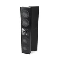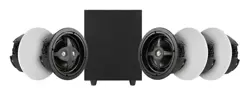
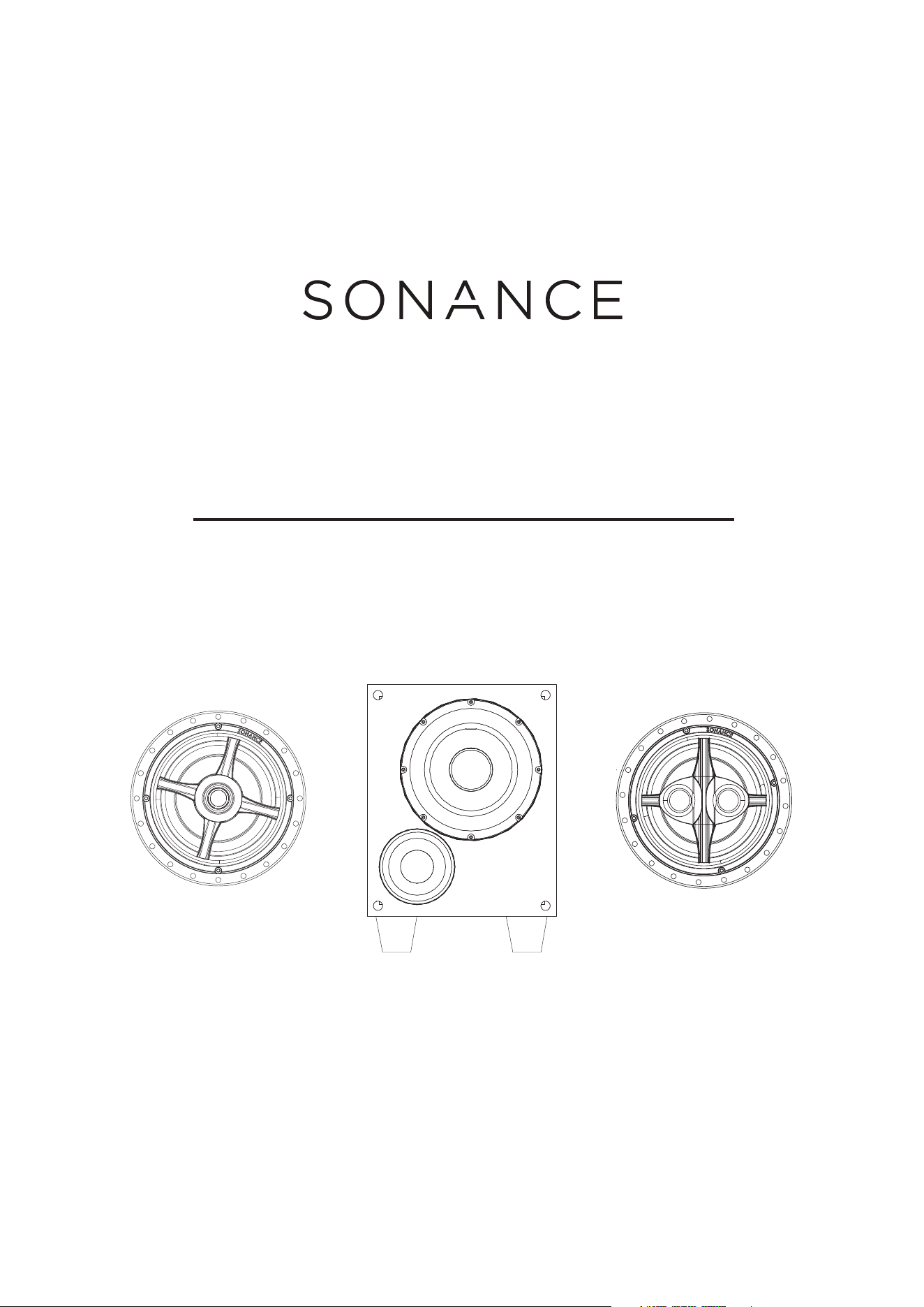
MAG5.1R
INSTRUCTION MANUAL
MAG6R
|
MS8 SUB
|
MAG6R SUR
IMPORTANT SAFETY INFORMATION
You should always follow these basic safety precautions when
using your Sonance MAG5.1R, to reduce the risk of fire, electric
shock, and injury to persons:
1. Read and retain instructions: Read all the safety and operating
instructions before operating the amplifier, and retain them for
future reference.
2. Heed warnings: Adhere to all warnings and precautions listed
on the amplifier and in the operating instructions.
3. Follow instructions: Follow all operating instructions.
4. Water: Never use the amplifier next to water.
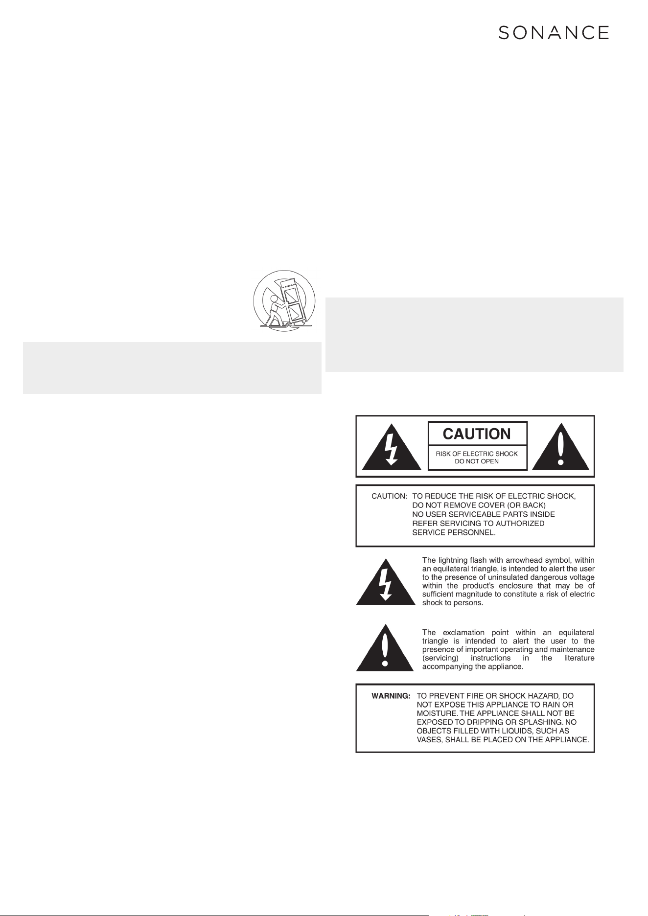
5. Carts and stands: The amplifier should be used
only with a cart or stand that is recommended
by the manufacturer. An amplifier and cart
combination should be moved with care.
6. CAUTION: TO PREVENT ELECTRIC SHOCK, DO NOT USE THE
POLARIZED PLUG WITH AN EXTENSION CORD, RECEPTACLE,
OR OTHER OUTLETS UNLESS THE BLADES CAN BE FULLY
INSERTED TO PREVENT BLADE EXPOSURE.
7. Ventilation: The Subwoofer should be situated so that its
location or position does not interfere with its proper ventilation.
For example, the subwoofer should not be situated on a bed,
sofa, rug, or similar surface that may block the ventilation
openings; or be placed in a built-in situation, such as a book case
or a cabinet, that may impede the flow of air over the subwoofer.
8. Heat: Situate the amplifier away from heat sources such
as radiators, stoves, or other appliances (including external
amplifiers) that produce heat.
9. Grounding or polarization: Grounding or polarization are
precautions that should be taken so that these attributes are
not defeated.
10. Power-cord protection: Route power supply cords so that
they will not be walked on or pinched by items placed on or
against them.
11. Cleaning: To clean the amplifier, use “canned air” or wipe
the amplifier with a soft cloth. Do not use solvents, as they may
damage the amplifier.
12. Non-use periods: Unplug the amplifier’s power cord from
the outlet when the amplifier will be left unused for a long period
of time.
13. Object entry: Care should be taken so that objects do not fall
through the opening of the enclosure.
14. Moisture: Do not expose the amplifier to dripping or
splashing. Do not place objects filled with liquids, such as vases,
on the amplifier.
15. Damage requiring service: Have the amplifier serviced by a
qualified service personnel when:
• The power supply cord or the plug has been damaged.
• Objects have fallen, or liquid has been spilled into the amplifier.
• The amplifier has been exposed to rain.
• The amplifier does not appear to operate normally or exhibits a
marked change in performance.
• The amplifier has been dropped, or the enclosure damaged.
16. Servicing: The user should not attempt to service the
amplifier beyond that described in the operating instructions. All
other servicing should be referred to qualified service personnel.
17. Lifting: Improper lifting of the 28 lbs. MS8 SUB can cause
personal injury.
18. Power requirement: Do not connect the Subwoofer to the
accessory outlet of any other component. A minimum 15 amp
(20 amp preferred) grounded wall outlet is required.
WARNING: THE POWER (MAINS) PLUG SERVES AS THE
AMPLIFIER’S DISCONNECT DEVICE. THE DISCONNECT DEVICE
SHALL REMAIN READILY OPERABLE DURING OPERATION.
TO ENSURE THAT THE DISCONNECT DEVICE (POWER PLUG)
IS EASILY ACCESSIBLE, THE USER SHALL NOT PLACE THE
AMPLIFIER IN A CONFINED AREA DURING OPERATION.
19. Storms: To prevent damage to components, unplug all
electronic equipment during thunderstorms.
INSTRUCTION MANUAL
MAG5.1R SYSTEM
2
INTRODUCTION
Thank you for purchasing MAG5.1R. When properly installed your
new speakers will give you years of entertainment pleasure.
BEFORE INSTALLATION
Determine the location for the speaker (see Speaker
Placement in column 1).
Perform an obstruction survey using a stud finder to be
certain that there are no studs, conduit, pipes, heating, ducts,
pocket doors or air returns in the ceiling cavity that will
interfere with the speaker.
If you are unsure about obstructions, drill a small hole in the
center of the outline and insert a coat hanger wire into the hole
to feel around for possible obstructions. Cut the mounting hole
using a keyhole or drywall saw, and run the speaker wires from
the mounting hole to the amplifier location.
INSTALLATION
Sonance Speakers feature integral Roto-Lock® mounting
system for quick mounting directly into existing ceilings.
1. Strip 1/4” – 1/2” (6mm – 12mm) of insulation from each
speaker lead. Twist the strands or tin the exposed wire with
solder to ensure that there are no stray strands.
2. The speaker’s terminals are spring-loaded. Push the top of
each terminal down to open the connector and insert the
exposed wires into the holes in the spring terminals.The
speaker’s positive spring terminal is labeled with a red dot;
the negative spring terminal is labeled with a black dot.
Doublecheck that you connected amplifier “+” to speaker “+”
and amplifier “–” to speaker “–”.
NOTE: STRAY STRANDS THAT TOUCH EACH OTHER CAN
CAUSE A SHORT-CIRCUIT THAT CAN DAMAGE THE AMPLIFIER.
NOTE: CONSULT LOCAL BUILDING CODES BEFORE RUNNING
SPEAKER WIRES THROUGH CEILINGS.
HOME THEATER SPEAKER PLACEMENT
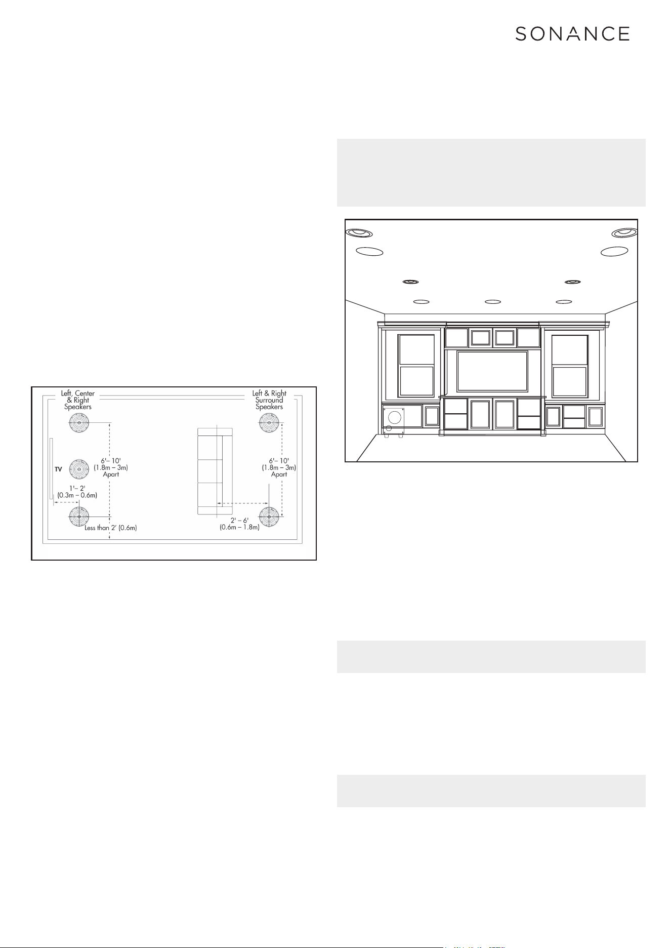
MAG6R - Left, Center & Right Speakers (see Figure 1)
• Place the left, center and right speakers 1 – 2 feet (0.3m –
0.6m) in front of the video screen, 6 – 10 feet (1.8m – 3m) apart,
with the center channel speaker as close to midway between the
left and right speakers as possible.
• The main listening position should be 4 – 10 feet (1.2m – 2m)
away from the speakers.
MAG6R SUR - Surround Speakers (see Figure 1)
• Locate the left and right surround speakers 2 – 6 feet (0.6m
–1.8m) behind the listening position. The speakers should be
6 – 10 feet (1.8m – 3m) apart.
SUBWOOFER PLACEMENT
As with any speaker, your Sonance MS8 SUB’s performance
will be influenced by its placement in your listening room.
However, since our ears do not hear directional sound at deep
bass frequencies, your subwoofer’s placement is not as critical
to its overall performance as is the placement of your system’s
other speakers. Therefore, your subwoofer will deliver superior
performance from a wide variety of room locations.
The following guidelines — plus some experimentation —
will help you get the best performance possible from your
subwoofer in your home theater space. Placing the subwoofer
as close as possible to the same plane as your main (left and
right) speakers will help your subwoofer’s sound properly
blend with the sound from your main speakers, creating a
solid, integrated soundstage that enhances the impact of
music and films.
We suggest starting with the subwoofer in line with your left
and right speakers, somewhere between either speaker and
the side wall (see Figure 2). Your subwoofer’s location relative
to walls will influence the amount of bass it produces —
placing the subwoofer next to a wall will increase bass output;
placing it in a corner will maximize its bass output. However,
corner placement can increase standing waves in the room
(peaks and dips in bass response related to the room’s
dimensions) that can make the subwoofer’s bass performance
sound uneven at dierent listening locations. Experiment with
dierent subwoofer locations until you find one that produces
strong bass that sounds clear (without boominess) at the
seating locations while maintaining the sound’s impact.
Your local authorized Sonance dealer is an expert in
audio/video system planning and installation. We strongly
recommend that you work with your dealer to ensure that
you get the best performance possible from your subwoofer.
NOTE: THESE SUBWOOFERS CAN PRODUCE ENOUGH BASS
ENERGY TO CAUSE OBJECTS IN THE ROOM TO RATTLE OR
BUZZ DURING PASSAGES WITH VERY STRONG BASS. IF THIS
HAPPENS, TRY RELOCATING THE ITEMS. IF THAT FAILS TO
STOP THE RATTLING YOU MAY HAVE TO REMOVE THE ITEMS.
BOX CONTENTS
MAG5.1R box contains:
(3) MAG6R speakers
(2) MAG6R SUR speakers
(1) MS8 SUB subwoofer
Figure 1: 5.1-Channel Home Theater Speaker Placement
Figure 2: 5.1-Channel Home Theater Subwoofer Placement
Figure 1: 5.1-Channel Home Theater Speaker Placement
Figure 2: 5.1-Channel Home Theater Subwoofer Placement
3
IMPORTANT: DO NOT CONNECT THE SUBWOOFER’S LINE
INPUTS AND SPEAKER INPUTS AT THE SAME TIME UNDER
ANY CONDITIONS.
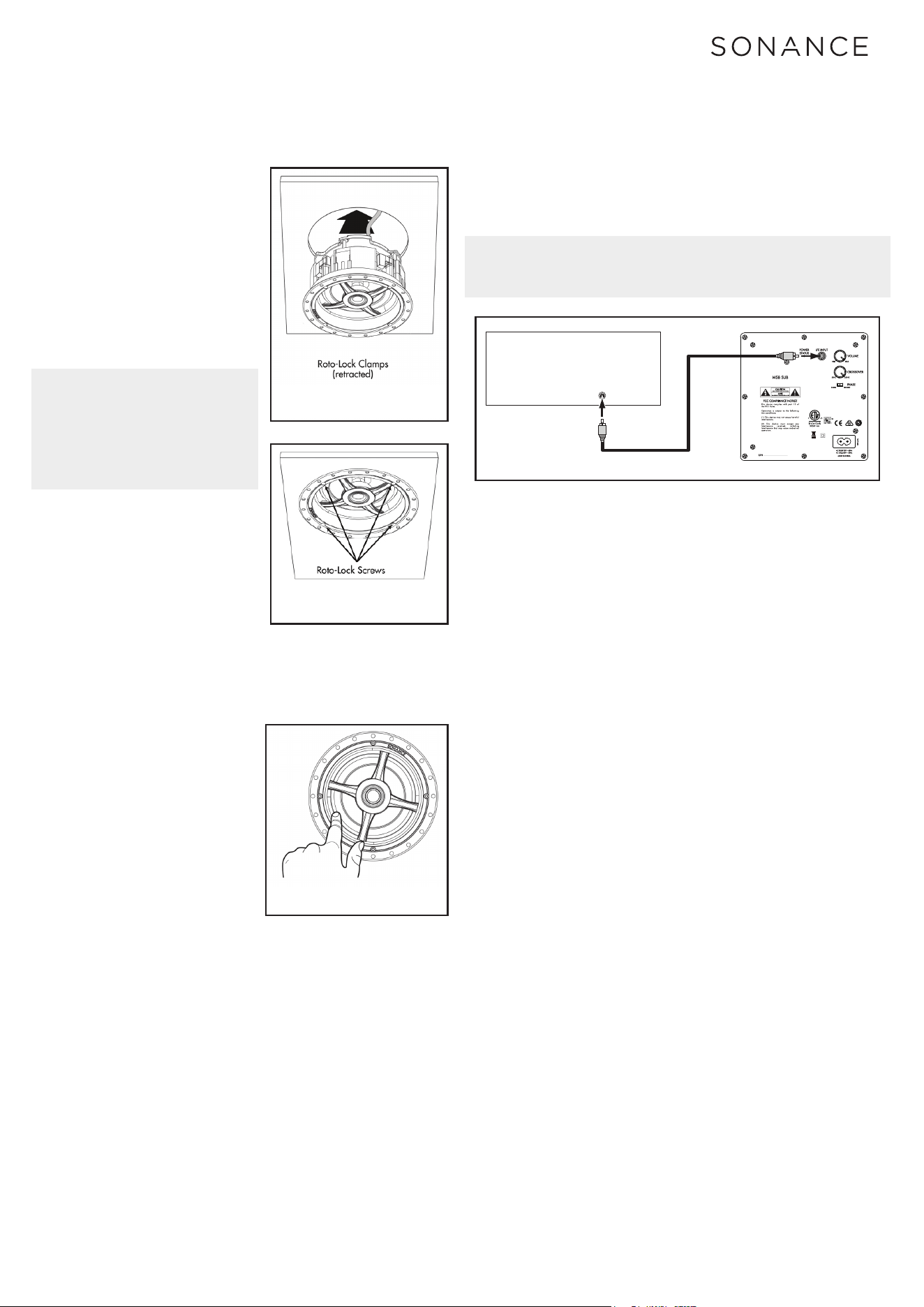
3. Make sure all the Roto-Lock toggle feet are retracted so
that they are tucked within the mounting hole’s border. Insert
the speaker into the hole in the ceiling (Figure 3). The Roto-
Lock system can accommodate a ceiling material thickness of
1-1/2” (38mm).
4. Tighten the screws on the
front of the speaker bae.
The Roto-Lock toggle feet
will automatically rotate into
position and begin clamping
the speaker (Figure 4). When
you notice resistance on
the screws the speaker has
been clamped successfully.
5. I M P O R T A N T : Always
use low torque settings;
NEVER over-tighten.
Figure 4: Tightening the RotoLock
Screws
Figure 6: Subwoofer Connection
Figure 5: Pivoting the MS6R Woofer
Figure 3: Inserting the Speaker Into
the Mounting Hole
SUBWOOFER
OUTPUT
Surround Sound
Processor/Receiver
AUDIO CABLE
CAN ICES-3 (B)/NMB-3(B)
Figure 4: Tightening the RotoLock
Screws
Figure 6: Subwoofer Connection
Figure 5: Pivoting the MS6R Woofer
Figure 3: Inserting the Speaker Into
the Mounting Hole
SUBWOOFER
OUTPUT
Surround Sound
Processor/Receiver
AUDIO CABLE
CAN ICES-3 (B)/NMB-3(B)
Figure 4: Tightening the RotoLock
Screws
Figure 6: Subwoofer Connection
Figure 5: Pivoting the MS6R Woofer
Figure 3: Inserting the Speaker Into
the Mounting Hole
SUBWOOFER
OUTPUT
Surround Sound
Processor/Receiver
AUDIO CABLE
CAN ICES-3 (B)/NMB-3(B)
Figure 4: Tightening the RotoLock
Screws
Figure 6: Subwoofer Connection
Figure 5: Pivoting the MS6R Woofer
Figure 3: Inserting the Speaker Into
the Mounting Hole
SUBWOOFER
OUTPUT
Surround Sound
Processor/Receiver
AUDIO CABLE
CAN ICES-3 (B)/NMB-3(B)
NOTE: ADJUST THE TENSION OF
THE ROTO-LOCK CLAMPS SO
THAT THE SPEAKER FRAME IS
FLAT. THIS WILL HELP ENSURE
THAT THE GRILLE CONTACTS THE
CEILING ALL THE WAY AROUND
THE SPEAKER FOR A PROPER FIT.
6. The micro-trim grille is
held in place by several small,
powerful magnets on the
speaker frame. Place the grille
against the speaker and the
magnets will hold it firmly in
place. When properly installed,
the grille trim should make
contact with the wall all the
way around the speaker.
SPEAKER ADJUSTMENTS
MAG6R – Left, Center and Right Channels
The woofer and tweeter of
the MAG6R should be pivoted
directly towards the listening
area. To pivot the drivers
apply light pressure to the ring
around the outside edge of the
woofer and tweeter, as shown
in Figure 5. Take care not to
touch or apply pressure to the
cone or dome itself.
MAG6R SUR
– Surround Channels
The woofer of the MAG6R SUR should be pivoted towards
a wall or window, away from the listeners to create a more
spacious surround presentation. To pivot the woofer apply
light pressure to the ring around the outside edge of the
woofer, as shown in Figure 5. Take care not to touch or apply
pressure to the cone itself.
MS8 SUB - CONNECTION
Your MS8 SUB will need both AC power and a standard
subwoofer cable with RCA connectors on both ends.
Follow the connection example in figure 6 below for
connecting the MS8 SUB directly to your A/V home theater
receiver. You’re A/V home theater receiver should have a LFE
or SUB OUT connector, the cable from your MS8 SUB should
be connected here.
MS8 SUB - CONNECTION
Your MS8 SUB will need both AC power and a standard
subwoofer cable with RCA connectors on both ends.
Follow the connection example in figure 6 below for
connecting the MS8 SUB directly to your A/V home theater
receiver. You’re A/V home theater receiver should have a LFE
or SUB OUT connector, the cable from your MS8 SUB should
be connected here.
MS8 SUB - CROSSOVER CONTROL
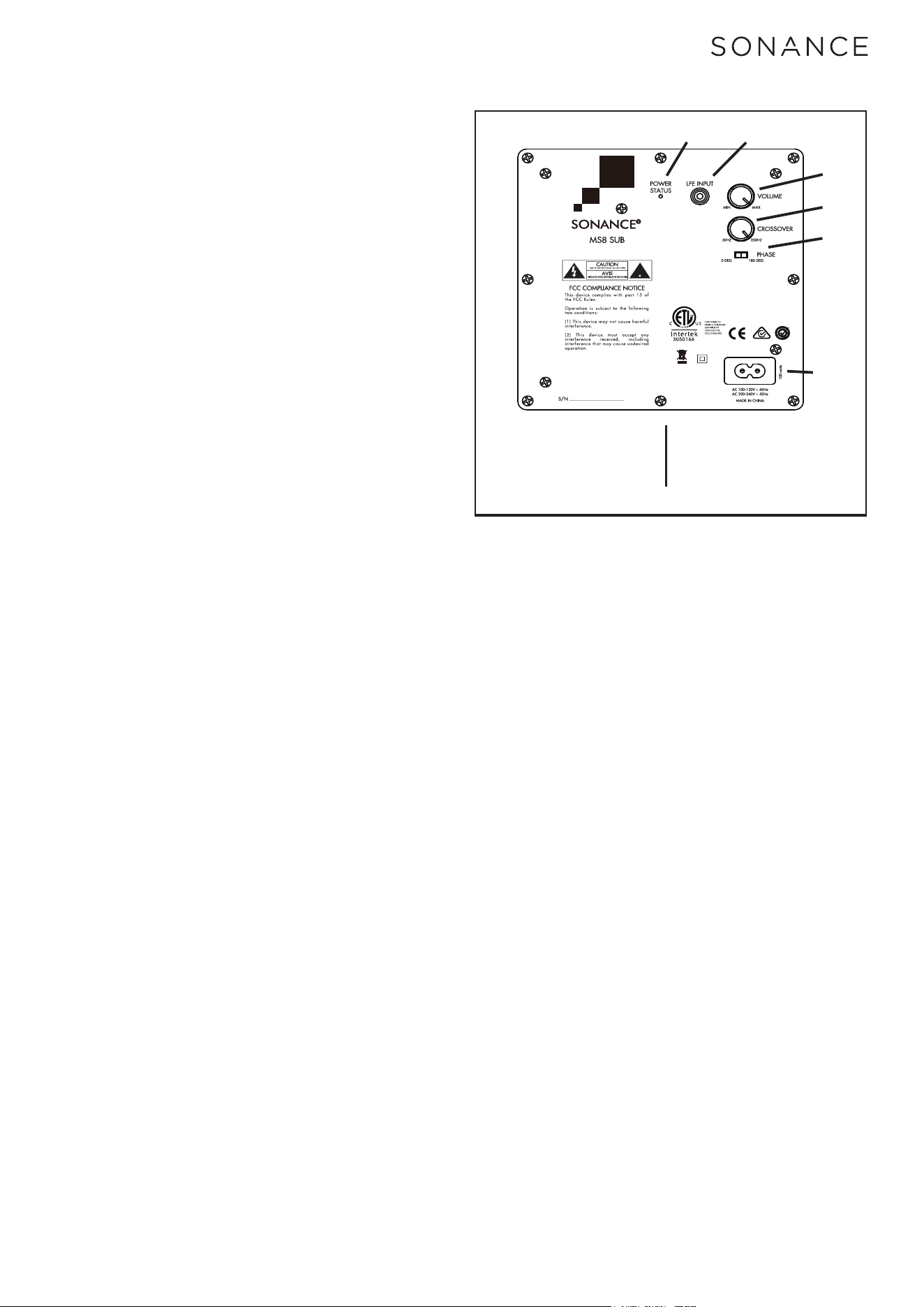
The crossover control on the rear panel of the MS8 SUB
(figure 7) should normally be set to the 250Hz or FULL
CLOCKWISE setting.
A/V home theater receivers have built in crossover filters
for subwoofer and satellite speakers. The settings for the
crossovers can be adjusted in the on screen menu for your
A/V home theater receiver. By setting the MS8 SUB in this
way the correct crossover filter will be applied in your A/V
home theater receiver and not in the subwoofer.
If you want to experiment with the crossover control on the
rear panel of the MS8 SUB the variable internal crossover
operates between 50Hz and 250Hz, with a crossover slope of
12dB/octave.
MS8 SUB - PHASE SWITCH
The phase switch on the rear panel of the MS8 SUB (figure 7)
should generally be left in the 0 DEG settings.
When the subwoofer’s PHASE switch is in the 0 position, a
positive input voltage will cause the woofer cone to move
out (towards the room). When the PHASE switch is in the 180
position, a positive input voltage will cause the woofer cone
to move in (away from the room).
There is no absolute correct setting for the PHASE switch.
Depending on the location of the subwoofer relative to your
main speakers and seating location, one of the settings will
produce a better match with the main speakers, improving
bass impact, and in some cases, improving overall bass level
as well.
To determine the correct setting of the PHASE switch, listen
to a movie or music with significant impactful bass content
with the switch in each position, it may be helpful to sit in the
normal listening position while someone else changes the
PHASE switch between 0 and 180. Leave the switch in the
position that produces audibly louder bass with more impact.
4
5
CAN ICES-3 (B)/NMB-3(B)
1 Power Status
2 Line Input
3 Volume Control
4 Crossover Conrol
5 Phase Switch
6 Power In
1
2
3
4
5
6
Figure 7: Subwoofer Rear-Panel Controls and Connections
MS8 SUB - VOLUME CONTROL
The volume control on the rear panel of the MS8 SUB (figure 7)
should normally be set to the MAX or FULL CLOCKWISE setting.
A/V home theater receivers have built in settings for volume
level for subwoofer and satellite speakers. The settings for
the volume volume can be adjusted in the on screen menu for
your A/V home theater receiver. By setting the MS8 SUB in
this way the correct output level will be applied in your A/V
home theater receiver and not in the subwoofer.
Further adjustment of the subwoofers level can be made
using the built in Volume Control. When setting the
subwoofer’s Volume control by ear, try to find a volume
setting where the bass sounds balanced on both music and
films. Listen to several dierent music recordings and film
soundtracks that contain strong bass passages and try to find
a setting for the Volume Control that doesn’t over-emphasize
the bass or make it sound weak.
MS8 SUB - AUTO-ON
The subwoofer is in the STANDBY mode whenever its power
cord is plugged-into a live AC outlet. When the subwoofer
detects an audio signal it will automatically turn ON (the rear-
panel On/Standby Indicator will illuminate Blue).
The subwoofer will continue to remain ON for approximately
15 minutes after no signal is detected on its input, then it will
return to STANDBY (the rear-panel On/Standby Indicator will
illuminate Red).

6
MAG5.1R SPECIFICATIONS
MAG6R SPEAKERS
Tweeter:
Woofer:
Frequency Response:
Imedance:
Power Handling:
Sensitivity:
Grille:
Dimensions (Dia.xD):
Cut-Out Diameter:
Weight:
MAG6 SUR SPEAKERS
Tweeter:
Woofer:
Frequency Response:
Imedance:
Power Handling:
Sensitivity:
Grille:
Dimensions (Dia.xD):
Cut-Out Diameter:
Weight:
MS8 SUB
Woofer:
Frequency Response:
Amplifier:
Crossover Frequency:
Inputs:
Grille Material:
Cabinet Finish:
Adjustments:
Dimensions (LxWxH):
Weight:
1” (25mm) silk dome, Ferrofluid-cooled,
pivoting, in acoustic back chamber
6 1/2” (165mm) glass fiber cone,
rubber surround, pivoting
45Hz – 20kHz ±3dB
8 ohms nominal; 6 ohms minimum
5 watts minimum; 125 watts maximum
89dB SPL (2.83V/1 meter)
Perforated steel
9 3/4” x 4 3/4” (248mm x 121mm)
8 1/4” (210mm)
3.7 lbs (1.7kg) each
Two 1” (25mm) silk dome, Ferrofluid-cooled,
in acoustic back chamber
6 1/2” (165mm) glass fiber cone,
rubber surround, pivoting
45Hz – 20kHz ±3dB
8 ohms nominal; 6 ohms minimum
5 watts minimum; 125 watts maximum
89dB SPL (2.83V/1 meter)
Perforated steel
9 3/4” x 4 3/4” (248mm x 121mm)
8 1/4” (210mm)
3.6 lbs (1.6kg) each
8” (203mm) Polypropylene cone
with a rubber surround
30Hz - 250 Hz ±3dB
100 Watts
50Hz ~ 250Hz (adjustable), 12dB/octave
Line-level LFE input
Black cloth
Textured vinyl
Level, Crossover and Phase
13 3/8” x 11 3/16” x 15 1/8”
28 lbs (12.7 kg)

LIMITED ONE (1) YEAR WARRANTY
Sonance warrants to the first end-user purchaser that this Sonance-brand product (“Product”), when purchased from an
authorized Sonance Dealer/Distributor, will be free from defective workmanship and materials for the period stated below.
Sonance will at its option and expense during the warranty period, either repair the defect or replace the Product with a new or
remanufactured Product or a reasonable equivalent.
EXCLUSIONS
TO THE EXTENT PERMITTED BY LAW, THE WARRANTY SET FORTH ABOVE IS IN LIEU OF, AND EXCLUSIVE OF, ALL OTHER
WARRANTIES, EXPRESS OR IMPLIED, AND IS THE SOLE AND EXCLUSIVE WARRANTY PROVIDED BY SONANCE. ALL OTHER
EXPRESS AND IMPLIED WARRANTIES, INCLUDING THE IMPLIED WARRANTIES OF MERCHANTABILITY, IMPLIED WARRANTY
OF FITNESS FOR USE, AND IMPLIED WARRANTY OF FITNESS FOR A PARTICULAR PURPOSE ARE SPECIFICALLY EXCLUDED.
No one is authorized to make or modify any warranties on behalf of Sonance. The warranty stated above is the sole and
exclusive remedy and Sonance’s performance shall constitute full and final satisfaction of all obligations, liabilities and claims
with respect to the Product.
IN ANY EVENT, SONANCE SHALL NOT BE LIABLE FOR CONSEQUENTIAL, INCIDENTAL, ECONOMIC, PROPERTY,
BODILY INJURY, OR PERSONAL INJURY DAMAGES ARISING FROM THE PRODUCT, ANY BREACH OF THIS WARRANTY
OR OTHERWISE.
This warranty statement gives you specific legal rights, and you may have other rights which vary from state to state. Some
states do not allow the exclusion of implied warranties or limitations of remedies, so the above exclusions and limitations may
not apply. If your state does not allow disclaimer of implied warranties, the duration of such implied warranties is limited to
period of Sonance’s express warranty.
Your Product Model & Description: Sonance MAG5.1R SYSTEM
Warranty Period for this Product: One (1) year from the date on the original sales receipt or invoice or other satisfactory proof
of purchase.
ADDITIONAL LIMITATIONS AND EXCLUSIONS
FROM WARRANTY COVERAGE
The warranty described above is non-transferable, applies only to the initial installation of the Product, does not include
installation of any repaired or replaced Product, does not include damage to allied or associated equipment which may
result for any reason from use with this Product, and does not include labor or parts caused by accident, disaster, negligence,
improper installation, misuse (e.g. overdriving the amplifier or speaker, excessive heat or cold or humidity, outdoor installation),
or from service or repair which has not been authorized by Sonance.
OBTAINING AUTHORIZED SERVICE
To qualify for the warranty, you must contact your authorized Sonance Dealer/Installer or call Sonance Customer Service at
(949) 492-7777 within the warranty period, must obtain a return merchandise authorization number (RMA), and must deliver
the Product to Sonance shipping prepaid during the warranty period, together with the original sales receipt, or invoice or other
satisfactory proof of purchase.
7

01.31.20
©2020 Sonance.
All rights reserved. Sonance and FastMount are registered trademarks of Dana Innovations.
Due to continuous product improvement, all features and specifications are subject to change without notice.
For the latest Sonance product specification information visit our website: www.sonance.com
SONANCE • 991 Calle Amanecer • San Clemente, CA 92673 USA
PHONE: (949) 492-7777 • FAX: (949) 361-5151 • Technical Support: (949) 492-7777
www.sonance.com
8