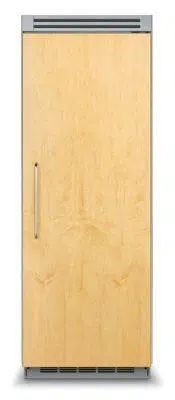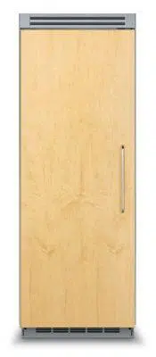
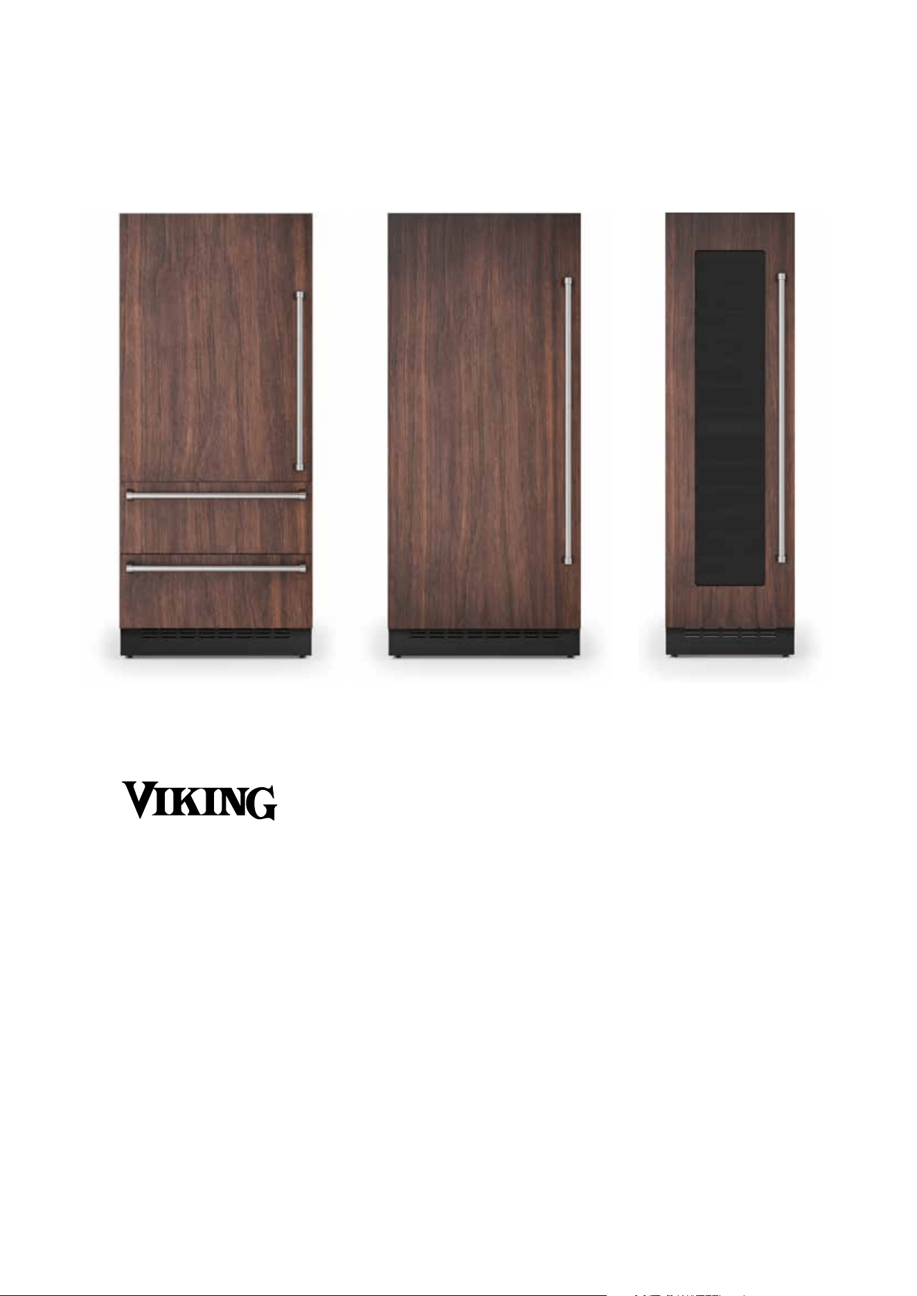
Installation Guide
All Refrigerator
FDREIC7240L - FDREIC7240R - FDREIC7300L - FDREIC7300R
FDREIC7360L - FDREIC7360R
All Freezer
FDFZIC7180L - FDFZIC7180R - FDFZIC7240L - FDFZIC7240R
FDFZIC7300L - FDFZIC7300R - FDFZIC7360L - FDFZIC7360R
Bottom Mount
FDBMIC7360L - FDBMIC7360R
Wine Cellar
FDWCIC7240L - FDWCIC7240R

2

1. IMPORTANT INSTRUCTIONS ...................................................................................................................................... 4
1.1 Important safety instructions ..................................................................................................................................................................4
1.2 Child safety ................................................................................................................................................................................................4
2. TECHNICAL REQUIREMENTS .................................................................................................................................... 5
2.1 Appliance features and installation requirements .........................................................................................................................5
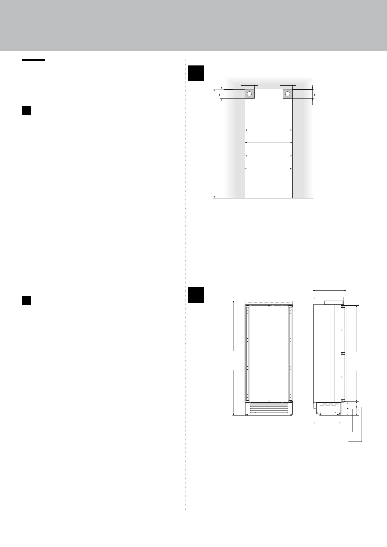
2.2 Installation cutout features: panel-ready all refrigerator / all freezer columns ...................................................................6
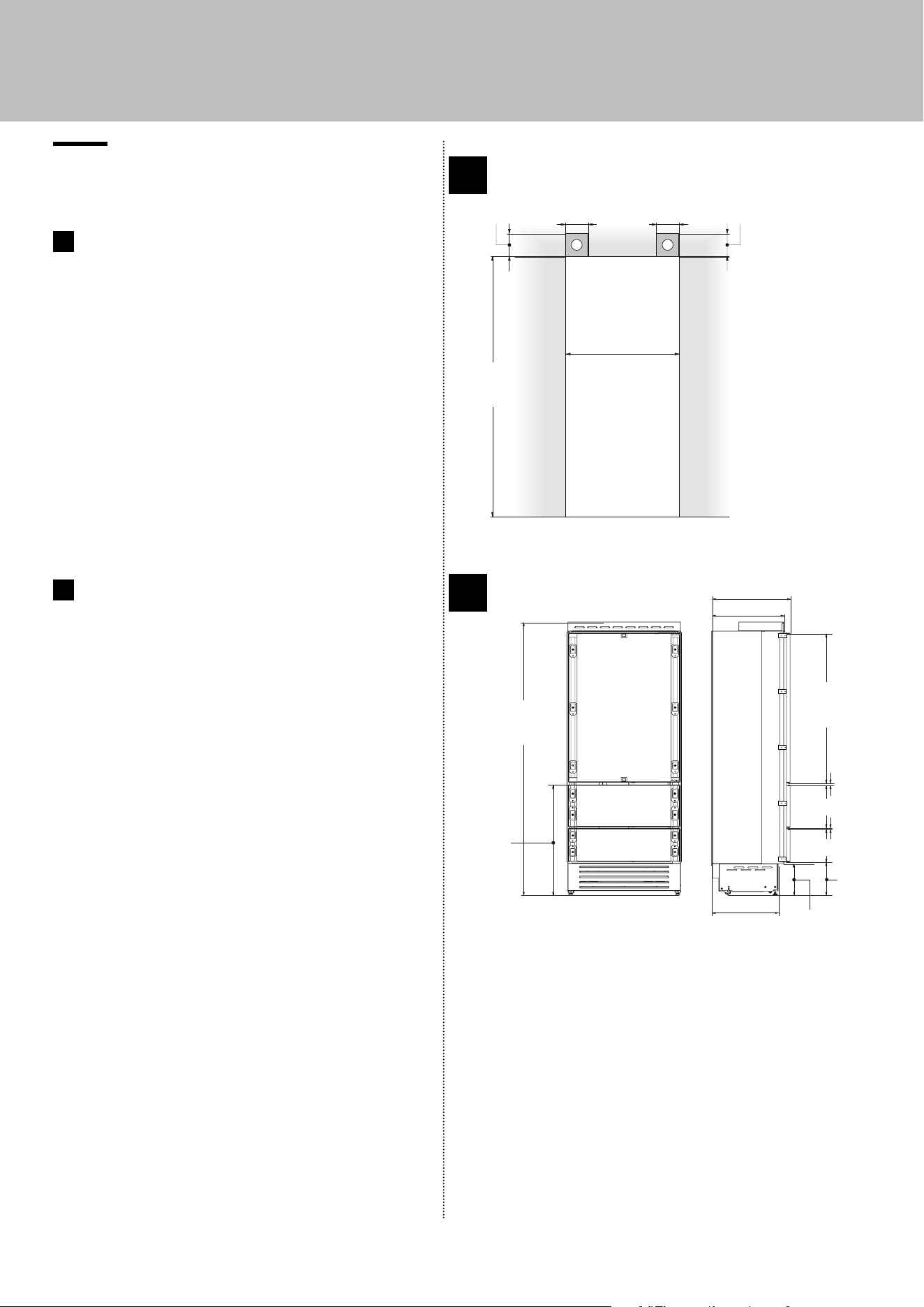
2.3 Installation cutout features: panel-ready bottom freezer ...........................................................................................................8
3. PREPARING FOR THE INSTALLATION ...................................................................................................................... 10
3.1 Transporting to installation site and unpacking .............................................................................................................................. 10
3.2 Electrical and water connection .........................................................................................................................................................10
3.3 Energy: Alternatives and Home Automation ..................................................................................................................................11
3.4 Leveling ......................................................................................................................................................................................................12
4. CUTOUT DIMENSIONS ............................................................................................................................................... 13
4.1 Cutout dimension for combined installation (for all models except XPro) ............................................................................. 13
5. PANEL MOUNTING ...................................................................................................................................................... 14
5.1 Overlay door-panel layout ....................................................................................................................................................................14
5.2 Center Drawer Panel Installation .......................................................................................................................................................16
5.3 Lower Drawer Panel Installation ........................................................................................................................................................17
5.4 Overlay panel layout for bottom freezer model with two bottom drawers ..........................................................................19
5.5 Overlay panel for all refrigerator / all Wine columns ...................................................................................................................20
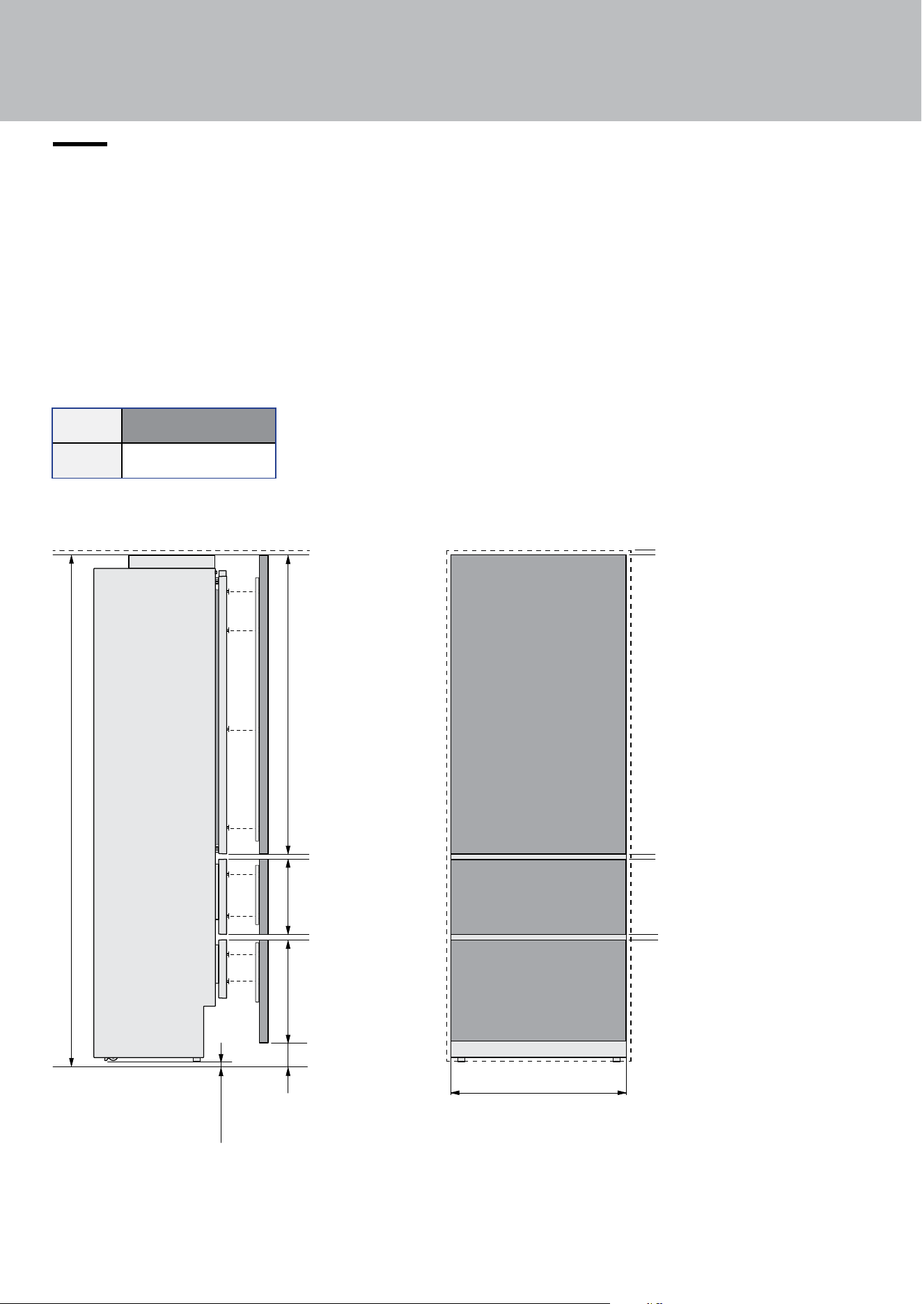
5.6 Overlay panel layout for Wine column with glass door .............................................................................................................21
5.7 Panels dimensions: bottom frezzer / two bottom drawer ..........................................................................................................22
5.8 Panel dimensions all refrigerator / all freezer column models ................................................................................................23
5.9 Mounting panels to the door ..............................................................................................................................................................24
5.10 Mounting panels to the drawer .........................................................................................................................................................24
5.11 Optional 1/8’’ panel reveal for multiple-unit installation .............................................................................................................. 25
6. INSTALLATION: ALL MODELS .................................................................................................................................... 26
6.1 Built-in installation of single appliance .............................................................................................................................................. 26
6.2 Built-in installation of two or more appliances ..............................................................................................................................26
6.3 Maximum cabinet depth over panel-ready appliance with single door panel ...................................................................31
7. COMPLETING THE INSTALLATION ............................................................................................................................ 32
7.1 Anti-tipping safety assembly .................................................................................................................................................................32
7.2 Ventilation ..................................................................................................................................................................................................33
7.3 Post-installation checklist ...................................................................................................................................................................... 34
7.4 Start-up ........................................................................................................................................................................................................34
3
EN
INDEX
4
1.1 Important safety instructions
Symbols used in the Guide:
Note
Tips for the correct use of the appliance
Important
Instructions for avoiding appliance
damage
Warning
Instructions for preventing injury
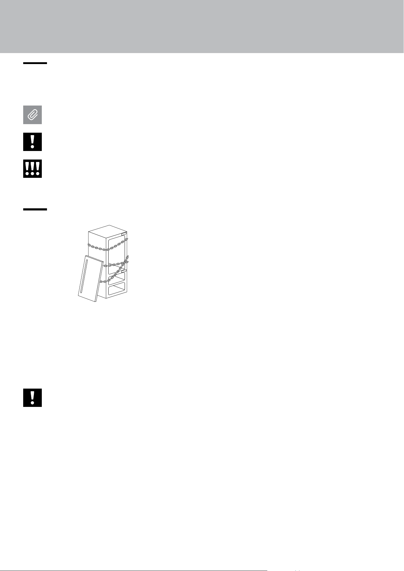
1.2 Child safety
DANGER: Risk of child entrapment. Before disposing
of your old refrigerator, freezer or wine cellar:
> Remove the doors
> Leave the shelves in place, so that children may
not easily climb inside.
Dimensions in parentheses are in inches.
Weights in parentheses are in pounds.
Temperatures in parentheses are
in degrees Fahrenheit.
1. IMPORTANT INSTRUCTIONS
5
EN
2.1 Appliance features and
installation requirements
Weight with
packaging
18”
up to 331 lbs. (150 kg.)
24”
up to 375 lbs. (170 kg.)
30”
up to 419 lbs. (190 kg.)
36”
up to 441 lbs. (200 kg.)
Voltage AC 110 - 120V 60Hz
Power supply
cable
90° Nema 5-15P
Dedicated circuit
breaker
15A
Potable water
supply pressure
from 0.05 MPa to 0.5 MPa
(0.5 Bar - 5 Bar)
PSI measurement 7.25psi - 72.5psi
Water connection 3/4” NPT
Provided
installation
accessories
- Anti-tipping kit
- Lateral mounting clips
(10 pieces)
- Overlay panel mounting kit
- Water connection kit
Additional
equipment needed
- Phillips screwdriver
- Wood drill
- 1/8” (2.5 mm) bit for wood
- 3/8” (8 mm) bit for walls
- 3/8” (10 mm) bit for walls
- 11/16” (17 mm) wrench
- 3/4” (19 mm) wrench
- 1/2” (13 mm) socket for
adjusting the rear
leveling legs
- 1/8” (2.5 mm) Allen wrench
for installing handles
Other provided
accessories
- Cleaning kit
2. TECHNICAL REQUIREMENTS
6
2. TECHNICAL REQUIREMENTS
2.2 Installation cutout features: pan-
el-ready all refrigerator / all freezer
columns
A
Minimum cutout height
84” (2134 mm)
Cutout width
36” model: 36” (914 mm)
30” model: 30” (762 mm)
24” model: 24” (610 mm)
18” model: 18” (457 mm)
Minimum cutout depth
24” (610 mm) + panel thickness for flush installation
Area to be left clear for the anti-tipping brackets
5” (127 mm) for both right and left sides
B
Appliance height
83 1/2” (2120 mm) + 1” (25 mm)
24 ¼” (615)
22 ¼” (565 )
19 ¾” (505)
A A
5" (127 mm) 5" (127 mm)
36": (914 mm)
18": (457 mm)
24": (610 mm)
30": (762 mm)
3 1/2"
(82 mm)
min 84”
(2134)
3 1/2"
(82 mm)
83 ½” (2120)
+1” (25)
9
¼”
(233)
+ 1” (25)
9
⅛”
(231 ) +
1” (25)
71 ¼”
(1808 )
610 (24”)
560 (22” )
19 ¾”(500 )
A A
127 mm (5") 127 mm (5")
36":914 (36”)
18": 457 (18”)
24": 610 (24”)
30": 762 (30”)
82 mm
(3 1/2")
min 2134
(84”)
82 mm
(3 1/2")
83 ½”(2120)
+1” (25)
9
¼”
(233 )
+1” (25))
9
⅛”
(231 )
+1” (25)
71 ¼”
(1808)
A
B
7
EN
2. TECHNICAL REQUIREMENTS
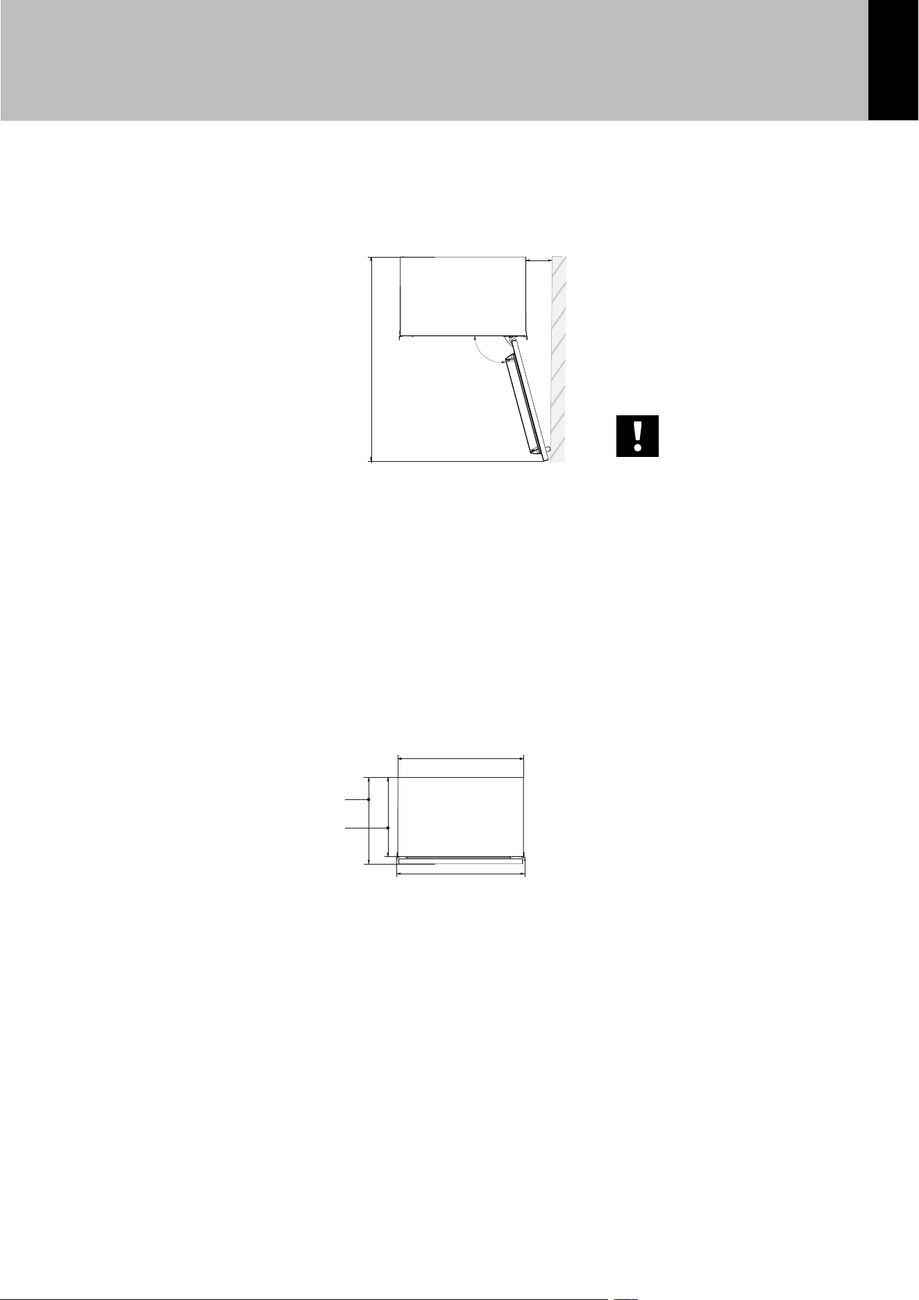
90° hinges available
to be ordered as spare
part
Door-Swing Clearance
Minimum distance from
the wall (hinge side)
Width of appliance body
Width of appliance with
mounting brackets installed
(eective width)
100°
36" model: 35 ⅞" (912 mm )
30" model: 29 ⅞" (760 mm)
24" model: 23 ⅞" (608 mm)
18" model: 17 ⅞" (455 mm)
36" model: 34 ⅞" (885 mm)
30" model: 28 ⅞" (735 mm)
24" model: 23" (585 mm)
18" model: 17 ⅛" (435 mm)
36" model: 6 ¼" (158 mm)
30" model: 5 ¼" (132 mm)
24" model: 4 ¼" (108 mm)
18" model: 3 ¼" (82 mm)
36" model: 58 ⅝" (1489 mm)
30" model: 52 ⅝" (1338 mm)
24" model: 46 ¾" (1187 mm)
18" model: 40
¾
" (1036 mm)
24" (610 mm
)
22" (560 mm)
100°
36" model: 35 ⅞" (912 mm )
30" model: 29 ⅞" (760 mm)
24" model: 23 ⅞" (608 mm)
18" model: 17 ⅞" (455 mm)
36" model: 34 ⅞" (885 mm)
30" model: 28 ⅞" (735 mm)
24" model: 23" (585 mm)
18" model: 17 ⅛" (435 mm)
36" model: 6 ¼" (158 mm)
30" model: 5 ¼" (132 mm)
24" model: 4 ¼" (108 mm)
18" model: 3 ¼" (82 mm)
36" model: 58 ⅝" (1489 mm
)
30" model: 52 ⅝" (1338 mm
)
24" model: 46 ¾" (1187 mm)
18" model: 40
¾
" (1036 mm)
24" (610 mm)
22" (560 mm)
8
2. TECHNICAL REQUIREMENTS
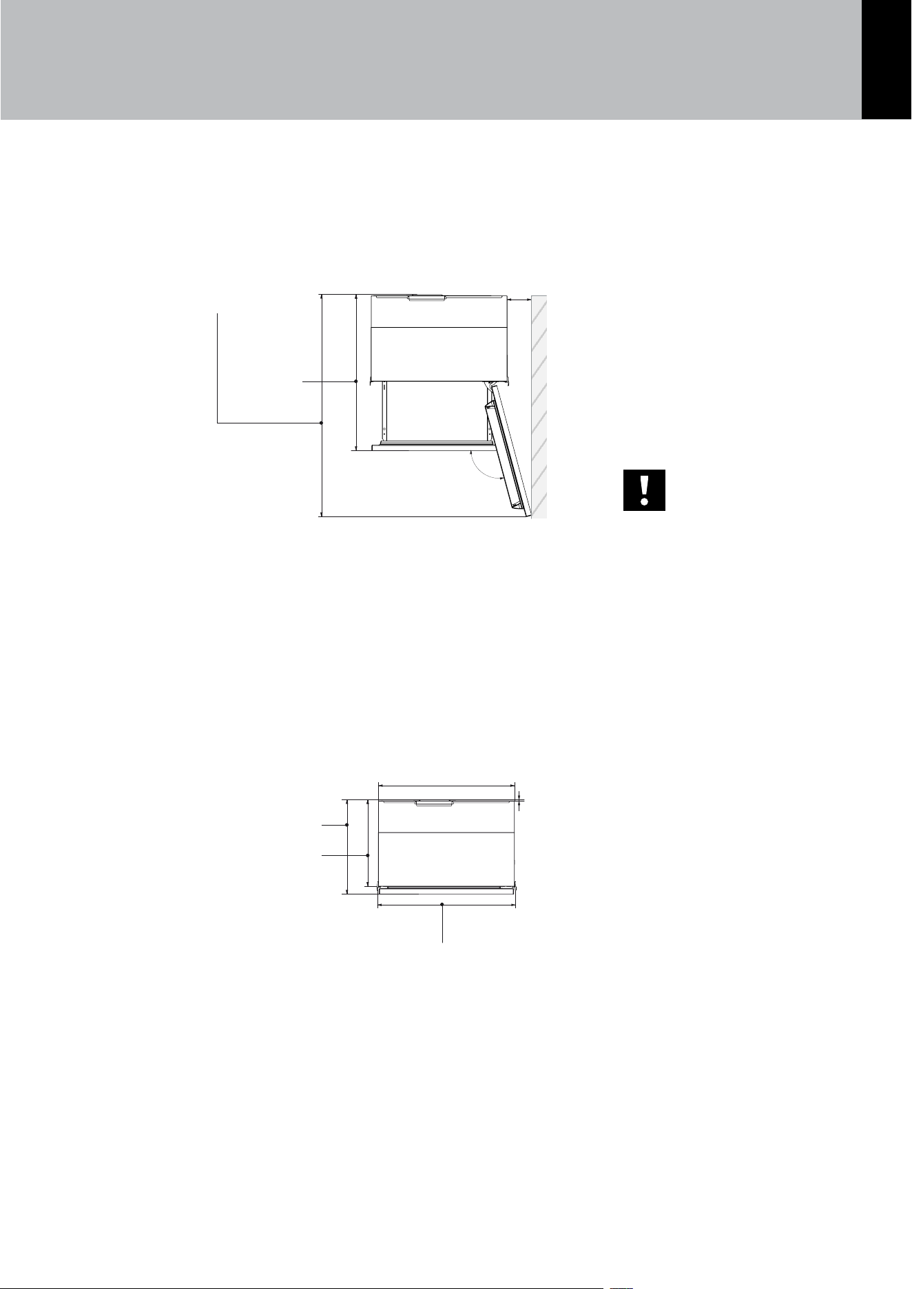
2.3 Installation cutout features:
panel-ready bottom freezer
A
Minimum cutout height
84” (2134 mm)
Cutout width
36” model: 36” (914 mm)
Minimum cutout depth
24” (610 mm) + panel thickness for flush installation
Area to be left clear for the anti-tipping brackets
5” (127 mm) for both right and left sides
B
Appliance height
83 1/2” (2120 mm) + 1” (25 mm)
B
A A
5 ½” (140 )5 ½” (140 )
36”: (914 mm)
24” (610)
22” (560)
19 ¾” (500)
⅜” (10)
4”(100 ) 4”(100 )
min 84”
(2134)
83 ½”(2120 )
+1” (25)
33 ¼”(846)
+1” (25)
46”
(1168)
¾” (20)
13” (330 )
10 1/4” (259)
9 ¾” (248)
+ 1” (25)
9 ⅛” (231)
+ 1” (25)
A
9
EN
2. TECHNICAL REQUIREMENTS
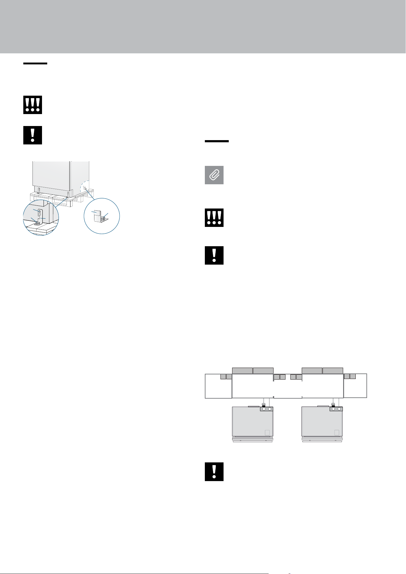
90° door swing available
using part 90STOP
Door-Swing Clearance
Minimum distance from
the wall (hinge side)
Width of appliance body
Width of appliance with
mounting brackets installed
(eective width)
100°
36” model: 35 ⅞" (912 mm)
36” model: 34 ⅞" (885 mm)
⅜” (10)
36” model: 6 ¼” (160 mm)
36” model: 58 ⅝” (1489 mm
)
39” (992)
24” (610)
22” (560)
100°
36” model: 35 ⅞" (912 mm)
36” model: 34 ⅞" (885 mm)
⅜” (10)
36” model: 6 ¼” (160 mm)
36” model: 58 ⅝” (1489 mm)
39” (992)
24” (610)
22” (560)
10
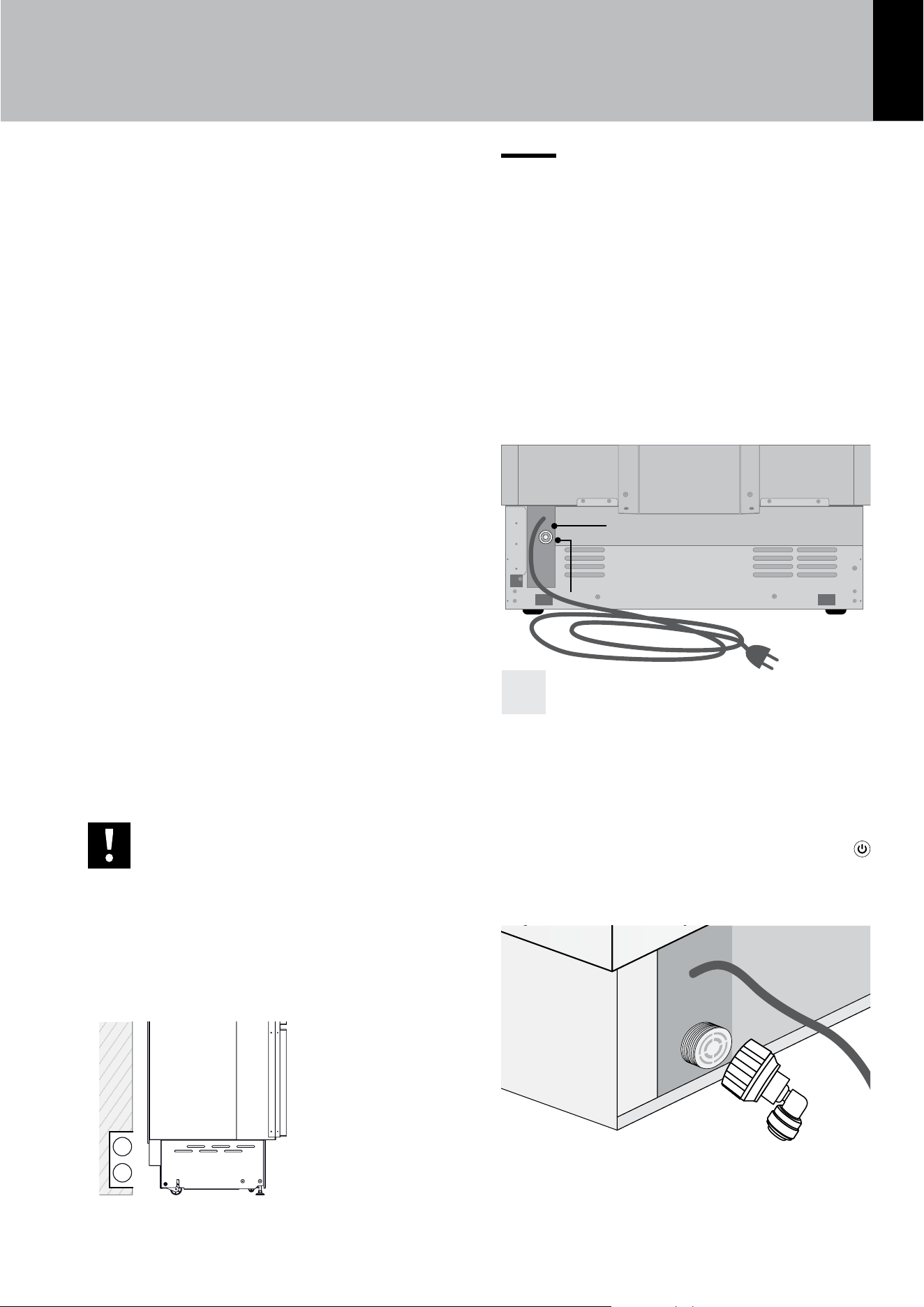
3.1 Transporting to installation site
and unpacking
The appliance is very heavy.
Exercise maximum caution during
handling to avoid injury.
The appliance should always be
transported in an upright position.
Never lean the production its front side.
As this appliance is large and heavy, check the
access to the site where it will be installed (door
size, maneuvering space in stairwells, etc.) before
transporting the appliance.
The appliance is attached to the base of the packaging
(pallet) by four bolts which can be removed using a
19-mm (3/4”) wrench.
We recommend using a manual transportation device
to move the appliance to the installation site, and only
removing the base of the packaging at this point.
The appliance should always be transported in an
upright position.
If this is not possible, transport the appliance lying on
its rear side. Once at the installation site, the appliance,
which is equipped with four wheels, can be taken o
the pallet and positioned in the installation area.
Proceed as follows:
> Remove the four bolts securing [ 1 ] the appliance
to the pallet by means of a 19-mm (3/4”) wrench or
socket.
> Remove the fixing brackets [ 3 ] and [ 4 ].
> To release the front fixing bracket [ 3 ], loosen the
rear wheel adjusting bolt [ 2 ] using a 13-mm (1/2”)
wrench or socket. Avoid straining this bolt one way
or the other at its stop points so as to avoid damaging
the rear leveling system.
Ensure that the front leveling legs are retracted, so
that all four wheels are able to contact the floor for
easiest maneuvering.
>
Remove the appliance and place it on the floor using
a suitable, heavy-duty hand truck from the back of the
unit.
3. PREPARING FOR THE INSTALLATION
Be very careful to avoid any damage to floors.
Delicate floors should be protected with plywood,
heavy cardboard or panels of similar material.
> At this point, adjust the rear rollers down (clockwise
on the leveling rod [ 2 ]) until they make contact with
the floor, and raise the rear of the appliance enough
so that it will roll freely
3.2 Electrical and water connection
The Built-in water filter cannot make any
water which is not already suitable for
human consumption safe to drink.
The appliance should be connected only
to a potable water supply system.
Do not use extension cords or adapters.
In the event that the water supply must be
turned o after the appliance has been
fully installed and connected to the water
supply (if applicable), and is operational,
disable the ice maker before the main
water supply is shut o to prevent the
appliance from entering a ‘NO WATER IN’
alarm state. Refer to the Use & Care Manual
for instructions on disabling the ice maker.
Electrical or water connections located
directly behind the appliance must be
recessed. Do not put the water shut-o
valve directly behind the appliance.
It should be in an accessible location.
E
E
E
E
E
W
W
W
W
W
E
W
• OVERHEAD VIEW •
EW
E W
EW
E W
1
4
1
2
3
ELECTICAL & WATER
CONNECTION
11
EN
3. PREPARING FOR THE INSTALLATION
The appliances are delivered from the factory
for operation at 110 V to 120V AC - 60 Hz (US and
Canada).
They are provided with a suitable supply cable and
plug to be connected to an appropriate 15 A socket
to provide eective grounding.
A dedicated 15-A circuit breaker should also be
installed and should be easily accessible, so that it
can be easily switched o before any installation or
maintenance is performed.
A 1/4” water line with an accessible shut-o valve must
be supplied in order to connect to the water supply
system (for appliances equipped with ice makers).
The appliance is provided with a water-adapter
elbow which is suitable for the recommended water
pressure and complies with the applicable food and
water regulations.
The water filter cartridge that is provided with the
appliance should be installed according to the
accompanying instructions. Please refer to the water
filter installation instructions contained in the water
filter kit. The solenoid connection on the appliance
has a 3/4” diameter but metric threading (NPT).
A standard threaded garden-hose connector such
as a braided stainless-steel hose typically found at
hardware stores will strip or damage the solenoid
threads. We recommend using only the supplied
1/4” quick-connect elbow adapter for connecting a
1/4” copper or polyethylene source water line to the
appliance.
Do not use extension cords and/or
multiple adapters for the power supply
connection.
ELECTRICAL AND WATER SUPPLY
BEHIND THE UNIT
ALL UNIT
3.3 Energy: Alternatives and Home
Automation
If energy is supplied through an alternative
energy power source (solar, geothermal, etc.),
or if home automation systems are installed
with carrier signals in the power lines, it may
be necessary to install an isolation transformer
(not supplied) to prevent interference with the
appliance’s electronics.
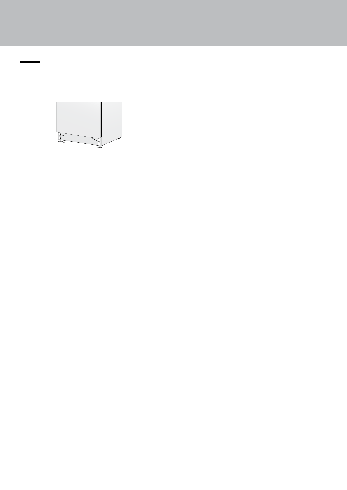
Proceed as follows:
> Unwind the electric cable, and connect it directly
to the wall socket.
> Make sure the appliance is in Stand-by mode and
that all lights are o; if not, press the Unit button
to switch it o.
> Connect the water cable behind the appliance [
1 ].
fig.1 Back of appliance
Water connection
Electrical connection
ALL UNITS
1
E
W
12
3. PREPARING FOR THE INSTALLATION
3.4 Leveling
Adjust the appliance level by means of the front
leveling feet [ 1 ] and the adjustable rear wheels
[ 2 ].
Proceed as follows:
> If necessary, remove the bottom plinth or grille
(it is kept in position by magnets), and adjust the
height of the leveling feet [ 1 ] using wrench.
> Next, adjust the height of the rear wheels by
turning the front adjusting bolts [ 2 ] clockwise
(raise) or counter-clockwise as required, use a
soket wrench (13mm).
Exercise caution if using a power driver for this,
and lower the clutch to prevent damaging the
leveling mechanism.
> Remount the bottom plinth or grille.
> If you have accidentally backed out the leveling
rod so that it is disengaged from the leveling
mechanism, you will need to pull the appliance
forward to access the rear of the base; locate
the locking nut, which will be loose under the
appliance, and re-thread the rod through the
leveling plate of the mechanism; then, reinstall
the locking nut and attempt to level the appliance
again.
1
2
1
2
13
EN
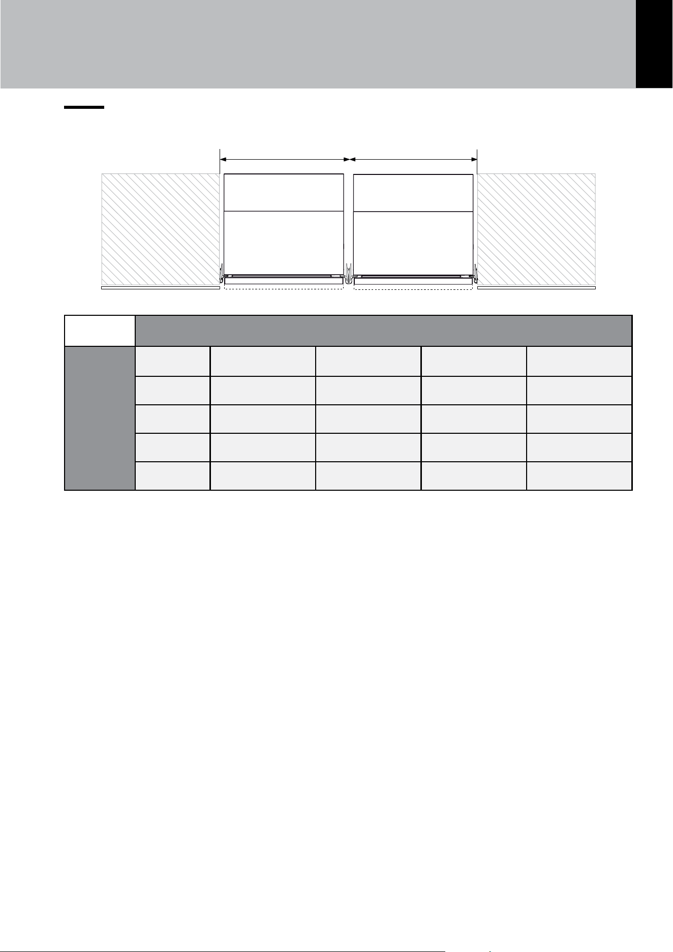
4.1 Cutout dimension for combined installation (for all models except XPro)
4. CUTOUT DIMENSIONS
A
B
18” 24” 30” 36”
18” 36” (914 mm) 42” (1067 mm) 48” (1220 mm) 54” (1372 mm)
24” 42” (1067 mm) 48” (1220 mm) 54” (1372 mm) 60” (1520 mm)
30” 48” (1220 mm) 54” (1372 mm) 60” (1520 mm) 66” (1676 mm)
36” 54” (1372 mm) 60” (1524 mm) 66” (1676 mm) 72” (1829 mm)
CORRECT SPACING BETWEEN APPLIANCES SHOWN LATER IN THIS MANUAL.
> Example: if appliance A is 24” and appliance B
is 36” the required opening width will be 24”+36”
= 60”
A
B
14
5. PANEL MOUNTING
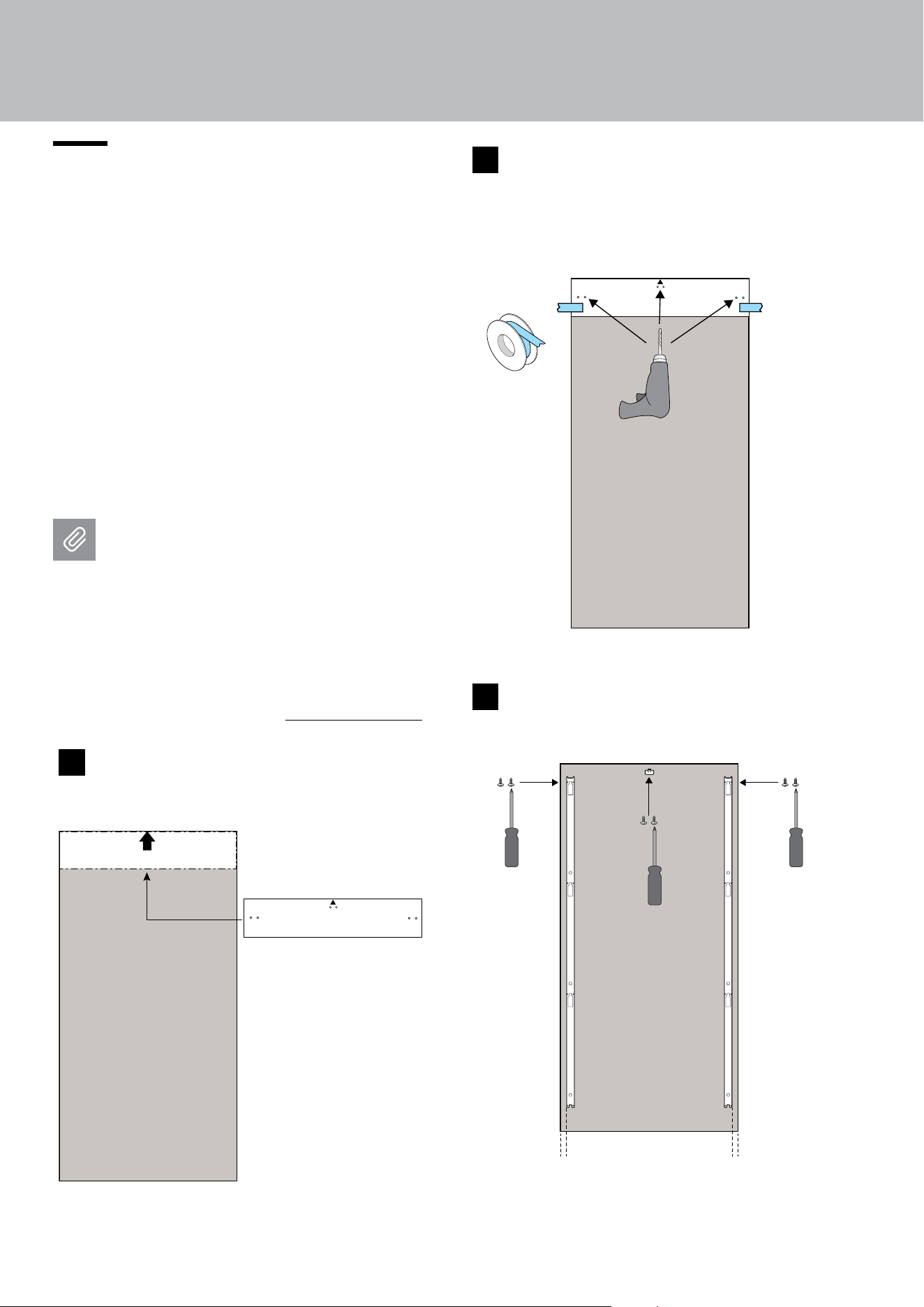
5.1 Overlay door-panel layout
The dimensions of the panels are indicated in
the table and drawings on the following pages.
However, depending on the requirements for
aligning with other kitchen structures, the door
panel can be higher than the upper edge of the
refrigerator door.
The panels must be mounted using special
brackets which attach to adjustable devices
provided on the door and drawer and with
brackets that anchor and adjust the panel’s
vertical orientation.
Brackets and fixing screws are provided with the
appliance and must be applied to the panel as
indicated.
For shaker or framed panel styles, it
may not be possible to ax the upper
or lower leveling brackets, unless the
cabinetmaker has made provisions for
mounting them with additional material
on the back of the panel.
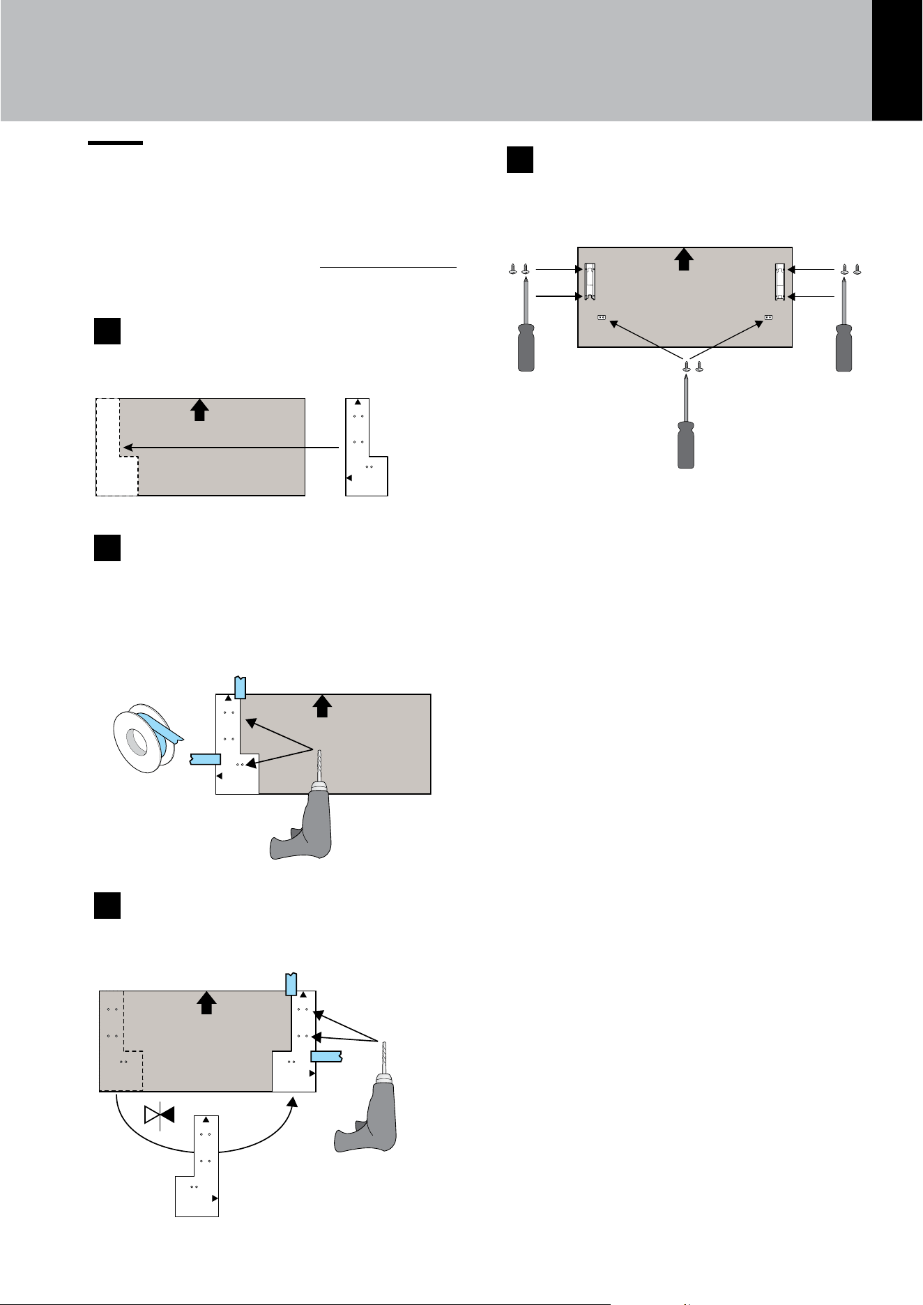
Proceed as follows:
To prepare the panels for mounting on the appli-
ance, follow these steps on the back of the panel.
1
Place the template at the top of the door,
making sure the arrow is pointing upwards.
TOP
TEMPLATE
2
Secure the template in place using
adhesive tape. Proceed to drill at the positions
of the pre-punched holes.
TEMPLATE
5/64”(2mm)
3
After removing the template, attach the
brackets to the top of the panel (Step 1).
111
15
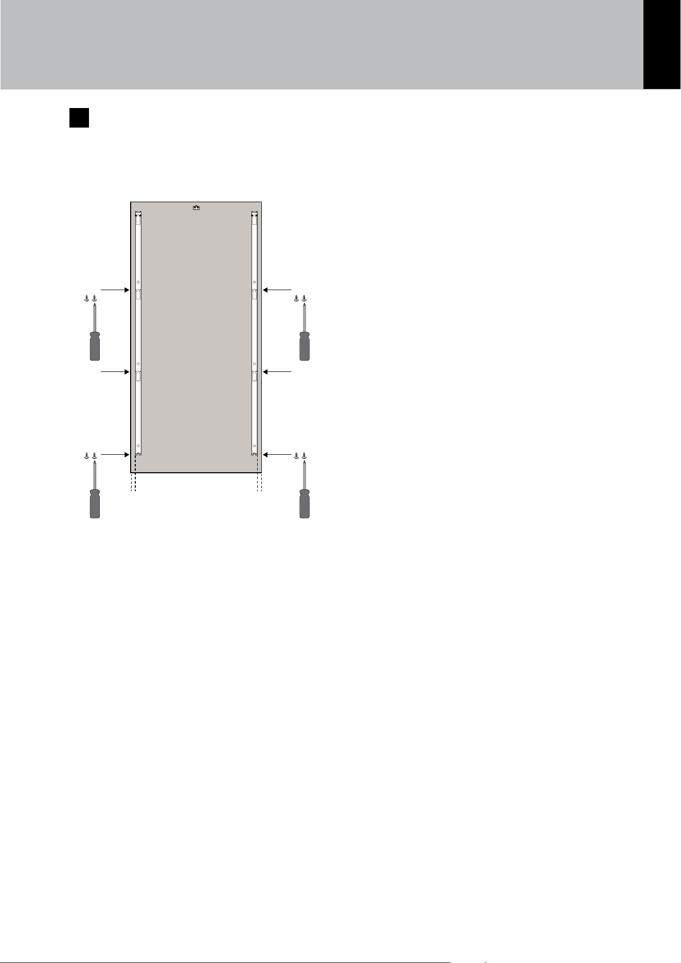
EN
4
Attach the brackets to the bottom of the
panel, making sure they are aligned with the
panel (Step 2).
Attach the brackets in the central part (Step 3).
2
2
33
33
16
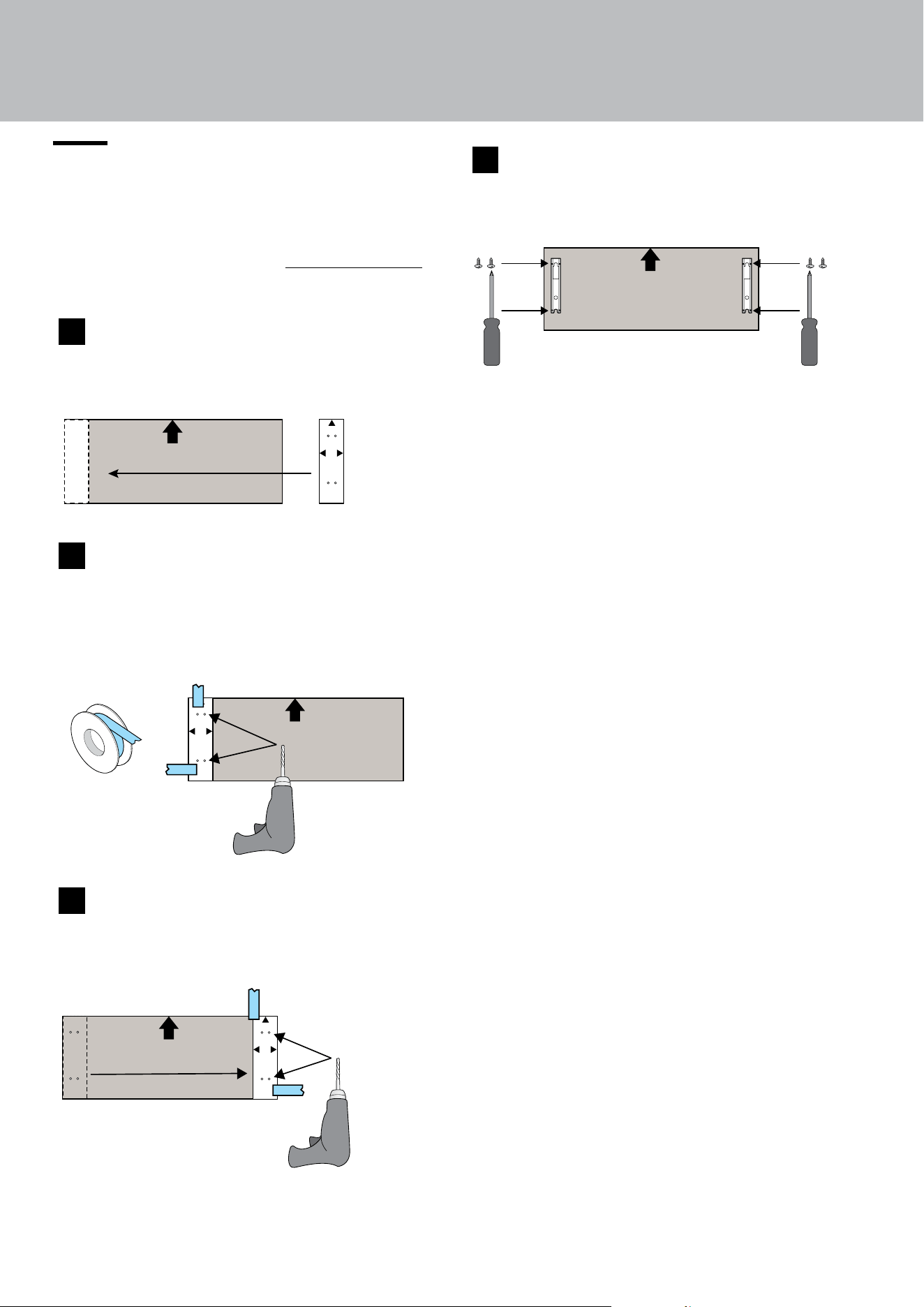
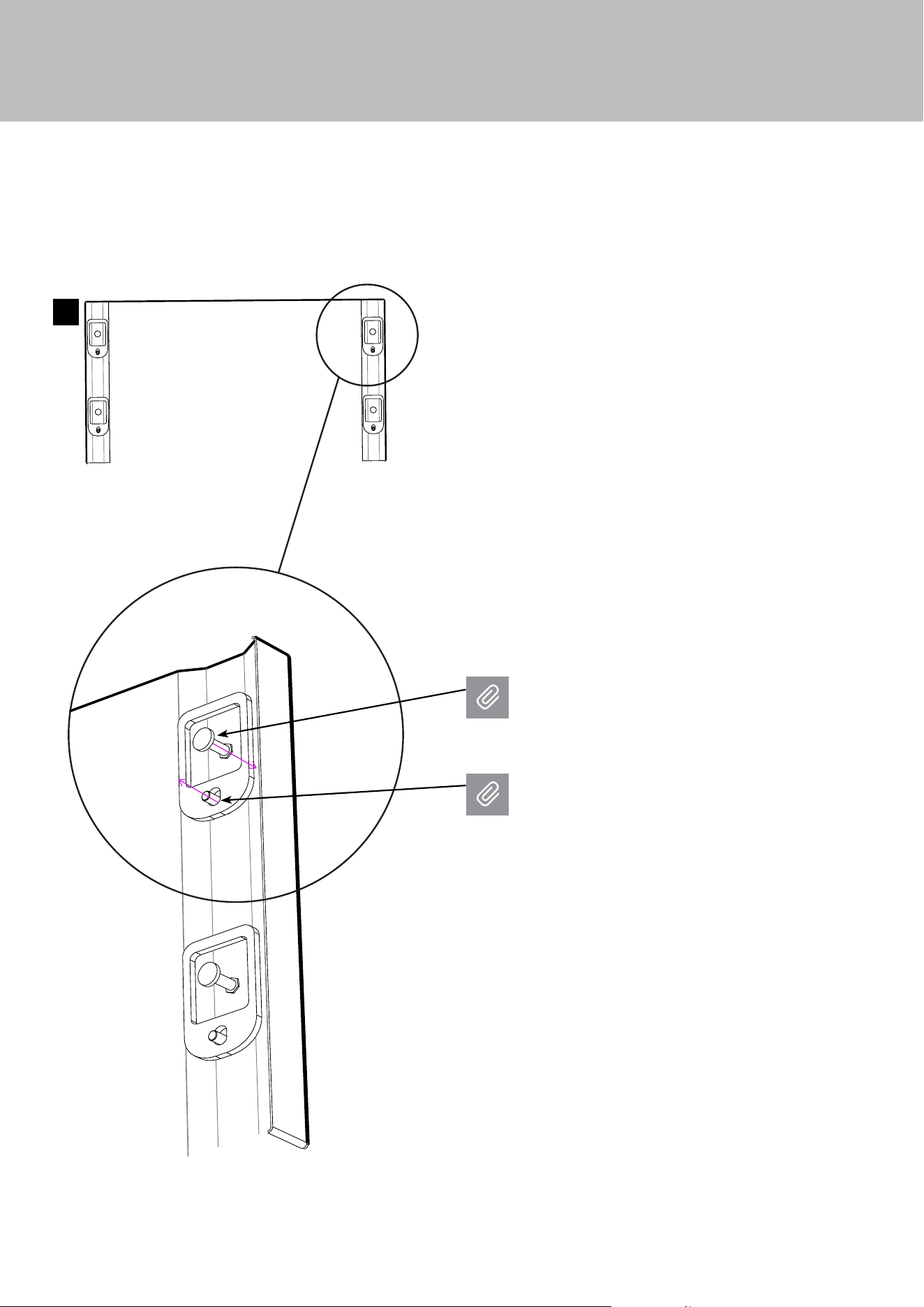
5.2 Center Drawer Panel Installation
Proceed as follows:
To prepare the panels for mounting on the appli-
ance, follow these steps on the back of the panel.
1
Place the template on the top of the drawer,
making sure the arrow is pointing upwards.
TEMPLA
TE
TOP
2
Secure the template in place using
adhesive tape. Proceed to drill at the positions
of the pre-punched holes. After drilling the
panel, move the template to the opposite side
of the panel.
TOP
5/64”(2mm)
3
After moving the template, secure it with
tape and drill at the designated points.
TOP
5/64”(2mm
)
4
After removing the template, attach the
brackets to the panel.
TOP
5. PANEL MOUNTING
17
EN
5.3 Lower Drawer Panel Installation
Proceed as follows:
To prepare the panels for mounting on the appli-
ance, follow these steps on the back of the panel.
1
Place the template on the top of the drawer,
ensuring the arrow is pointing upwards.
TOP
TEMPLA
TE
2
Secure the template in place using
adhesive tape. Proceed to drill at the positions
of the pre-punched holes. After drilling the
panel, move the template to the opposite side
of the panel.
TOP
5/64”(2mm)
3
After moving the template, secure it with
tape and drill at the designated points.
TOP
5/64”(2mm
)
4
After removing the template, attach the
brackets to the panel.
TOP
18
5. PANEL MOUNTING
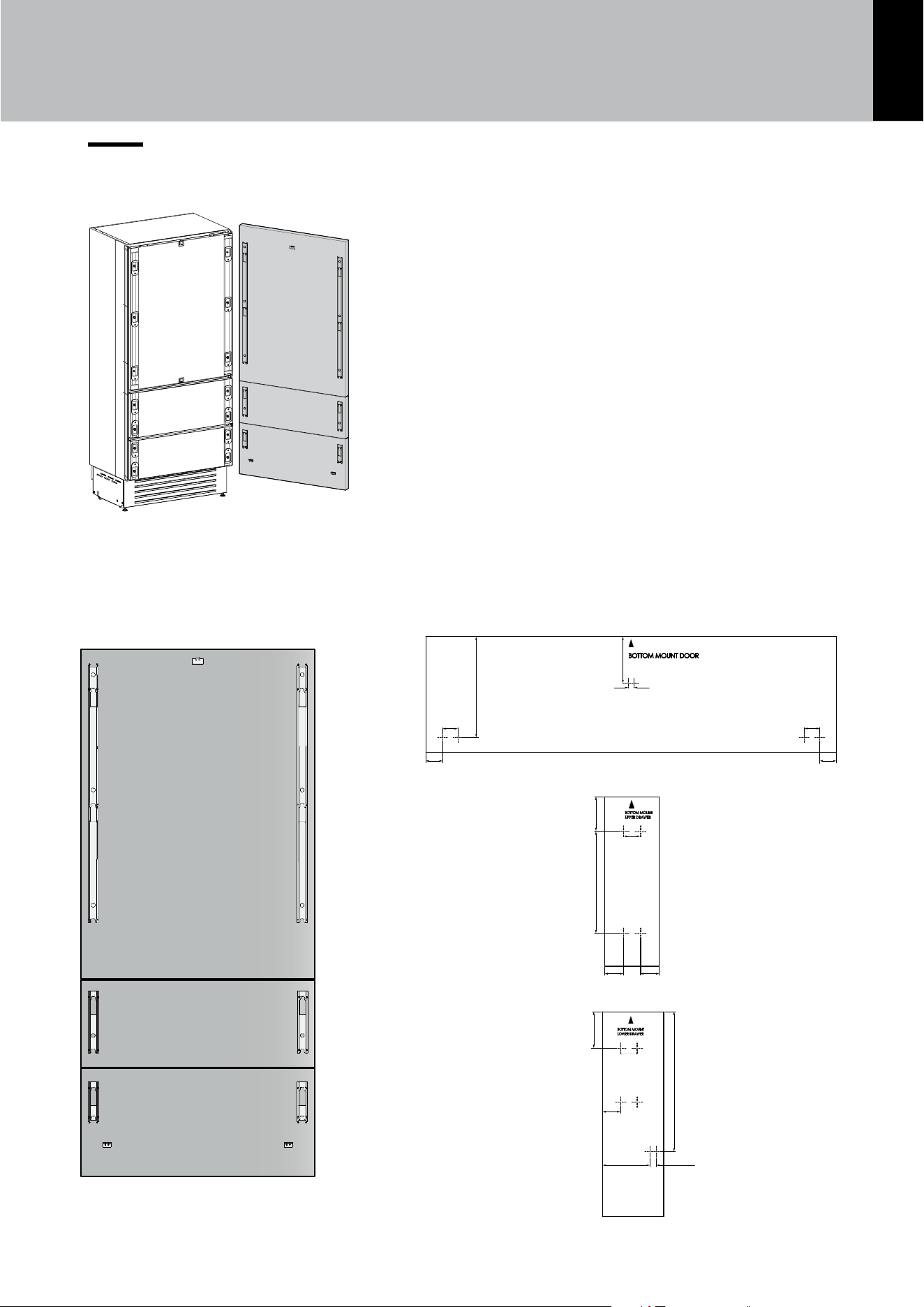
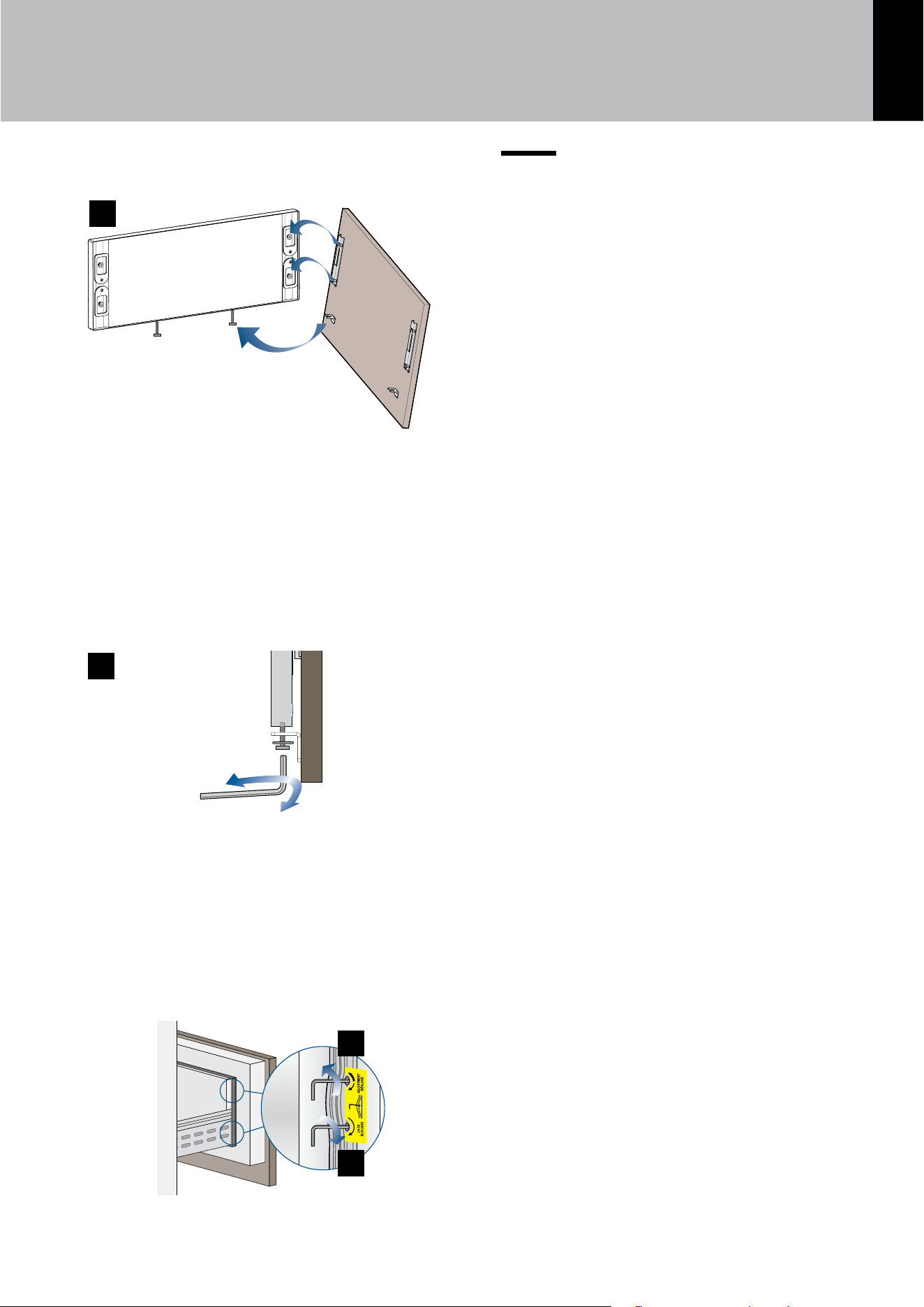
> Prepare the appliance door for mounting the panels by threading the shoulder bolts into the recessed
receivers and the set screws into the other hole [ 7 ]. Make sure the end with the Allen wrench socket
is threaded into the door and not on the visible end. Thread it in far enough so that it is flush with the
face of the appliance door so as to avoid interfering with hanging the panel. You will adjust these later.
Shoulder bolt for hanging brackets and
for pulling panel in toward the appliance
door.
Set screw to set-depth/z-axis position of
panel and apply opposing pressure at
each fixing point to ‘lock’ panel in place.
7
19
EN
5. PANEL MOUNTING
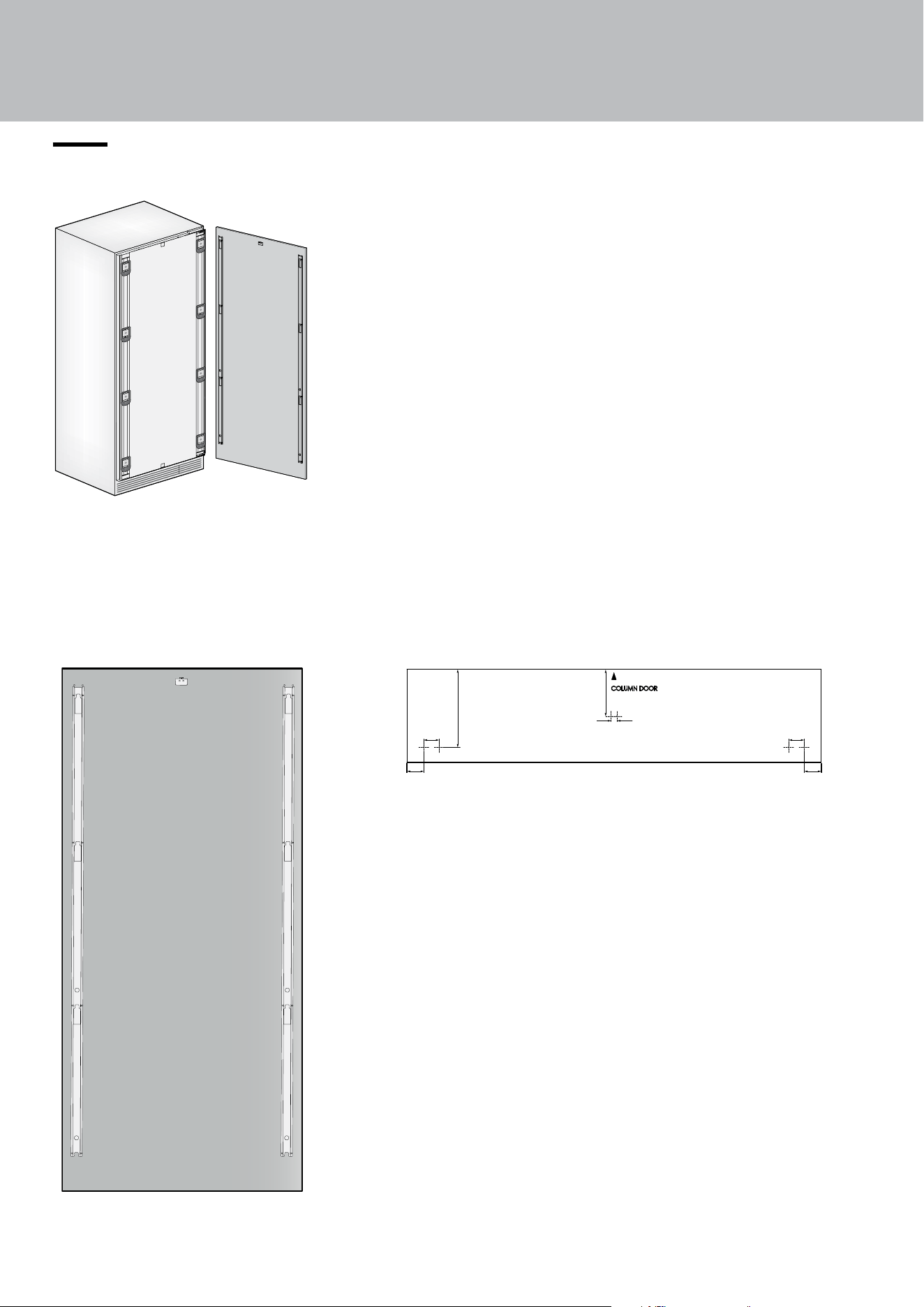
5.4 Overlay panel layout for bottom freezer model with two bottom drawers
Template:
2’’11/16 (75)
8’’(203)
1’’29/64 (37) 1’’29/64 (37)
1’’1/3 (34)
1’’ 1/3 (34)
2’’11/16 (75)
11’’11/32 (288)
1’’ 29/64 (37)
3’’ 27/32 (97,5)
1/2 (13)
Hole positions and
bracket orientation:
8” 25/32 (223)
1’’1/3 (34)
1’’1/3 (34)
1’’ 29/64 (37)
1’’ 29/64 (37)
4” 1/16 (103)
1/2 (13)
20
5. PANEL MOUNTING
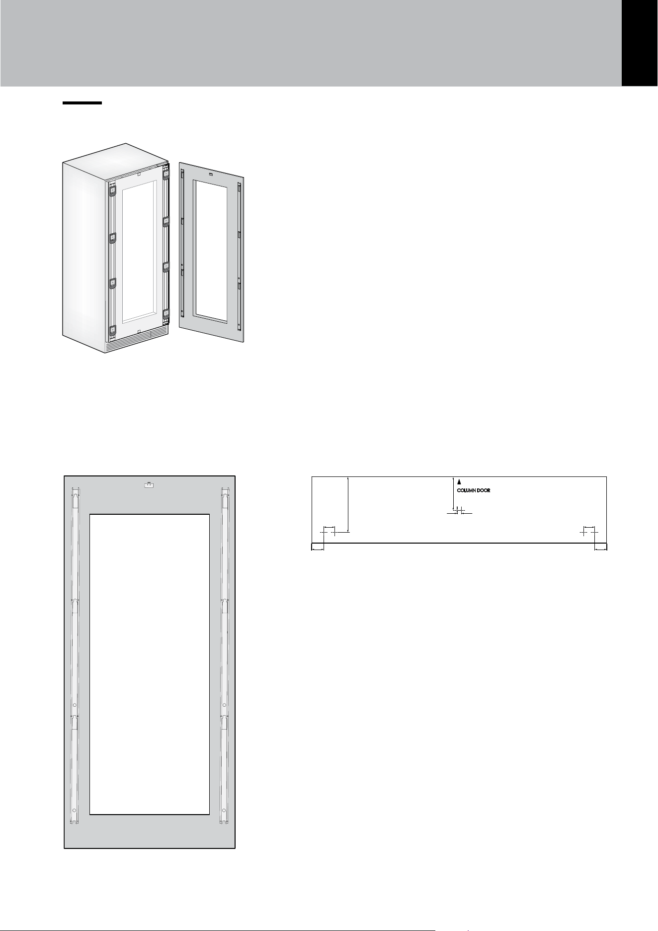
5.5 Overlay panel for all refrigerator / all Wine columns
Hole positions and
bracket orientation:
Template:
1
6” 9/16 (167)
1’’1/3 (34)
1’’1/3 (34)
1’’ 29/64 (37) 1’’ 29/64 (37)
3” 29/32 (99)
1/2 (13)
21
EN
5. PANEL MOUNTING
5.6 Overlay panel layout for Wine column with glass door
Hole positions and
bracket orientation:
Template:
1
6” 9/16 (167)
1’’1/3 (34)
1’’1/3 (34)
1’’ 29/64 (37) 1’’ 29/64 (37)
3” 29/32 (99)
1/2 (13)
22
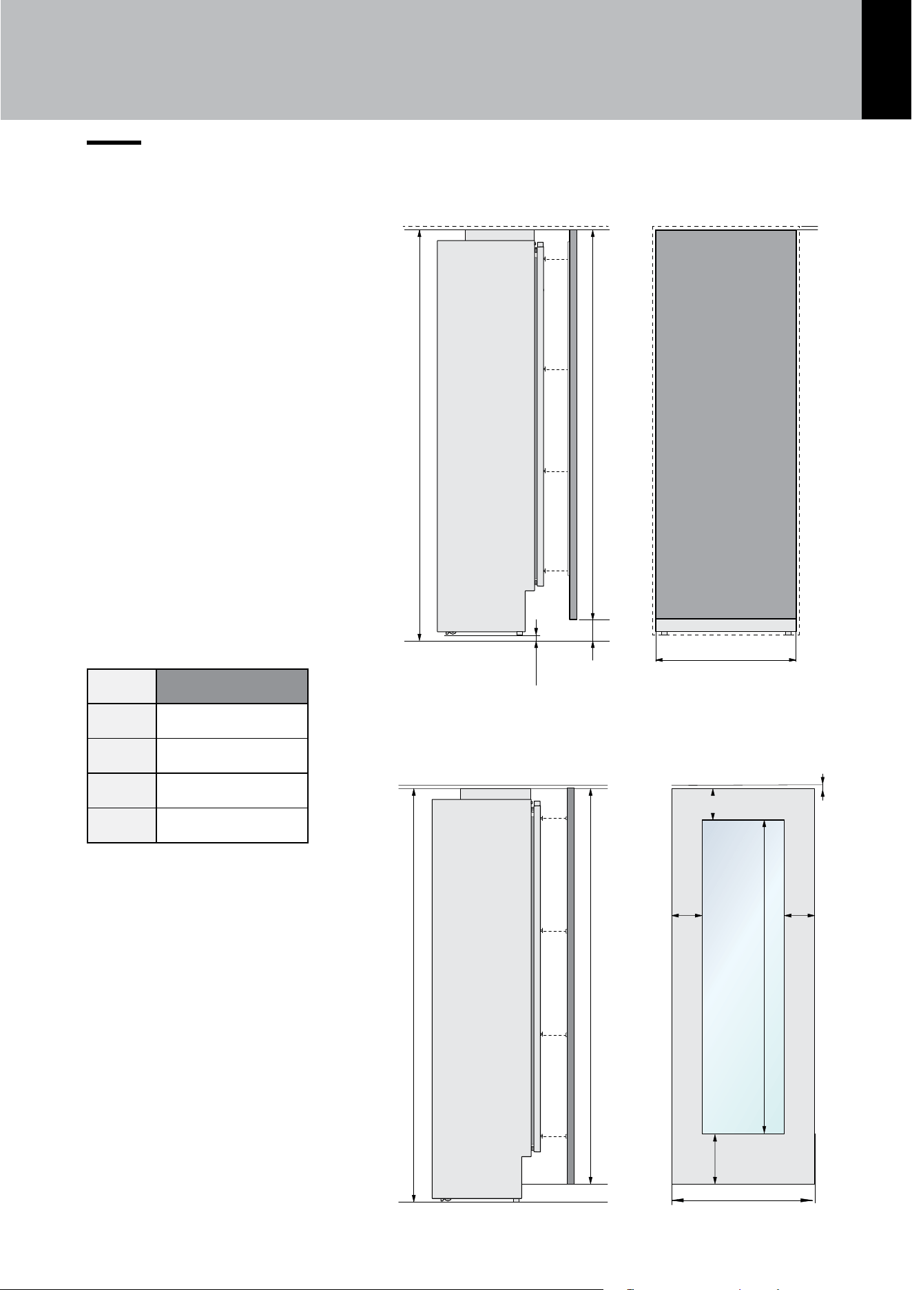
5.7 Panels dimensions: bottom frezzer / two bottom drawer
Panels thicknesses may range between 3/4” (18 mm) and 1-1/8” (28 mm).
The maximum door panel weight is 51 lbs. (23 kg), and the maximum drawer panels weight is 25 lbs. (11 kg).
Exceeding these weights could void your warranty for any service issues which can be attributed to overweight
panels.
The hinging mechanism on Viking Refrigeration Product is considered to be `Zero-clearance.' The door widths
and drawer widths specified below assume that the minimum cutout width is being used, and a 1/8” (3.5 mm)
reveal is desired around the panels. Adjust your panel dimensions according to your own design criteria consi-
dering your cutout width and your reveal. Minimum reveal/gap should not be less than 1/16” (1.5 mm).
5. PANEL MOUNTING
WIDTH
DOOR/DRAWER WIDTH A
36”
35 3/4” (908)
Adjustment area for the feet
16 5⁄8” (422,2)
4” (101,6)
13 1⁄8” (333,3) 49 ¾” (1265)
83 ½" (2121) + 1" (25)
A
3⁄16”
(4,76)
3⁄16” (4,76)
1⁄8” (3,2)
23
EN
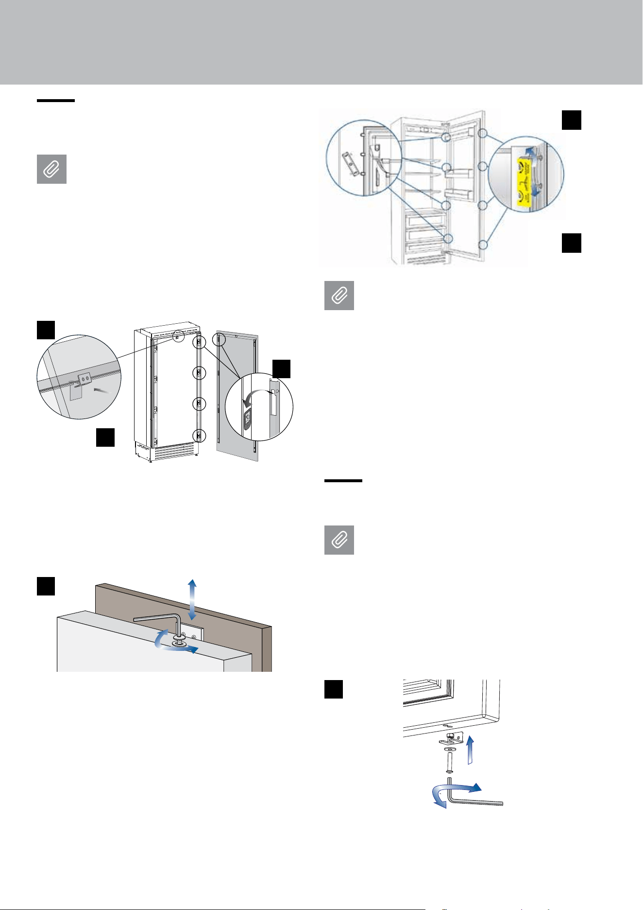
5.8 Panel dimensions all refrigerator / all freezer / wine column models
WIDTH
DOOR WIDTH A
36”
35 3/4” (908)
30”
29 3/4” (756)
24”
23 3/4” (604)
18”
17 3/4” (451)
5. PANEL MOUNTING
Panels with thickness ranging between
3/4” (19 mm) and 1-1/8” (28 mm).
Door panels with max weight of 75 lbs.
(34 kg)
Exceeding these weights could void
your warranty for any service issues
which can be attributed to overweight
panels.
The hinging mechanism on Viking
Refrigeration Product is considered to
be `Zero-clearance.' The door widths
and drawer widths specified below
assume that the minimum cutout width
is being used, and a 1/8” (3.5-mm)
reveal is desired around the panels.
Adjust your panel dimensions according
to your own design criteria considering
your cutout width and your reveal.
Minimum reveal/gap should not be less
than 1/16” (1.5 mm).
For fridge and freezer columns
Adjustment area for the feet
83 1/2" (2120) + 1" (25 )
79
¾ ”
(2027
)
4
”
(100
)
A
1⁄8” (3,2)
For wine columns
83 ½" (2121) + 1" (25)
min 76 1⁄8” (1933)
max 79
7⁄8” (
2028.8
)
5 3⁄8”
(135)
5 3⁄8”
(135)
min 7 7⁄8” (200)
1⁄8” (3.2
)
10” (254)
23 ¾” (603.2)
62” (1574.6)
24
5. PANEL MOUNTING
5.9 Mounting panels to the door
Once all brackets and small brackets
have been applied to the panels, you can
begin installing the bottom drawer.
> Hook the panel to the fixing devices starting
from the top aligning brackets [ 6 ].
> At this point, alignment between the panel and
adjacent cabinets can be adjusted using the
alignment brackets and small brackets [ 7 ] and
[ 8 ].
> Vertical alignment: tighten or loosen the screw
in the brackets to raise or lower the panel [ 9 ].
> Depth alignment: working from the inside of
the door, after lifting up the magnetic seal on the
handle side and rotating the plastic covers on
the hinge side, adjust the panel position in the
Z-direction by adjusting the shoulder bolts and
setscrews with the 5/32” (4-mm) Allen wrench in
combination with each other and finally locking
each mounting position in place [10 & 11].
Once the front panel has been adjusted,
check that the gasket has been repositioned
correctly to ensure that the door/drawer is
closing correctly and to avoid operational
errors in the unit.
The product handle is not included in the appliance
packaging but must be purchased separately.
For handle installation, please refer to the
instructions included in handle packaging.
5.10 Mounting panels to the drawer
Once all brackets and handles have been
applied to the panels, you can begin in-
stalling the bottom drawer.
Proceed as follows:
> Partially tighten the screw to the nut in the ap-
pliance drawer [ 1 ].
7
8
6
10
11
9
1
25
EN
5. PANEL MOUNTING
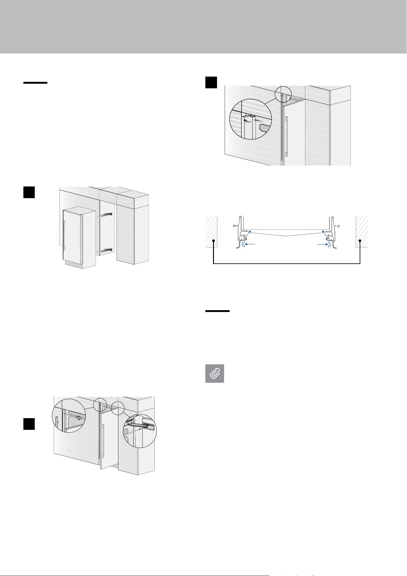
> Hook the bottom drawer panel starting from
the adjustment bolts on the bottom [ 2 ].
> It is now possible to align the height of the
panels to adjacent cabinets using the lower ali-
gnment bolts and brackets [ 3 ] and tightening or
untightening the screws into position as needed.
With the screw slightly tightened, manually move
the panel sideways to align it to the other panels
on the unit or other adjacent structures.
Set the bottom adjustment bolts using the lock nut
once you are satisfied with the height alignment.
> Depth alignment: working from the inside of the
drawer, after lifting up the magnetic seal or rota-
ting the cover plate where necessary, adjust the
panel position in the Z-direction by adjusting the
shoulder bolts and setscrews with the 4-mm Allen
wrench in combination with each other and finally
locking each mounting position in place [ 4 & 5 ].
5.11 Optional 1/8’’ panel reveal for
multiple-unit installation
Note: when joining multiple units using overlay
panels as per the instructions herein for single
install, the resulting gap/reveal will be 3/16”
between panels. If you would like to maintain
~1/8” of reveal between all the panel and gables,
you can add 1/16” to the width dimension of the
specified panel for each unit.
For example: joining a 24”+30”+36” unit:
Opening width: 24”+30”+36”=90”
Standard panel widths based on single-unit
installations: 23-3/4”+29-3/4”+35-3/4”=89-1/4”
This leaves an overall space of 3/4” divided by 4
gaps = 3/16”
If you add 1/16” to each panel: 23-13/16”+29-
13/16”+35-13/16”=89-7/16”
This would result in an overall space of 9/16”
divided by 4 gaps = 9/64” (~1/8”) between panels
2
4
5
3
26
6. INSTALLATION: ALL MODELS
IMPORTANT: The following installation instructions apply to all Viking refrigeration models.
6.1 Built-in installation of single
appliance
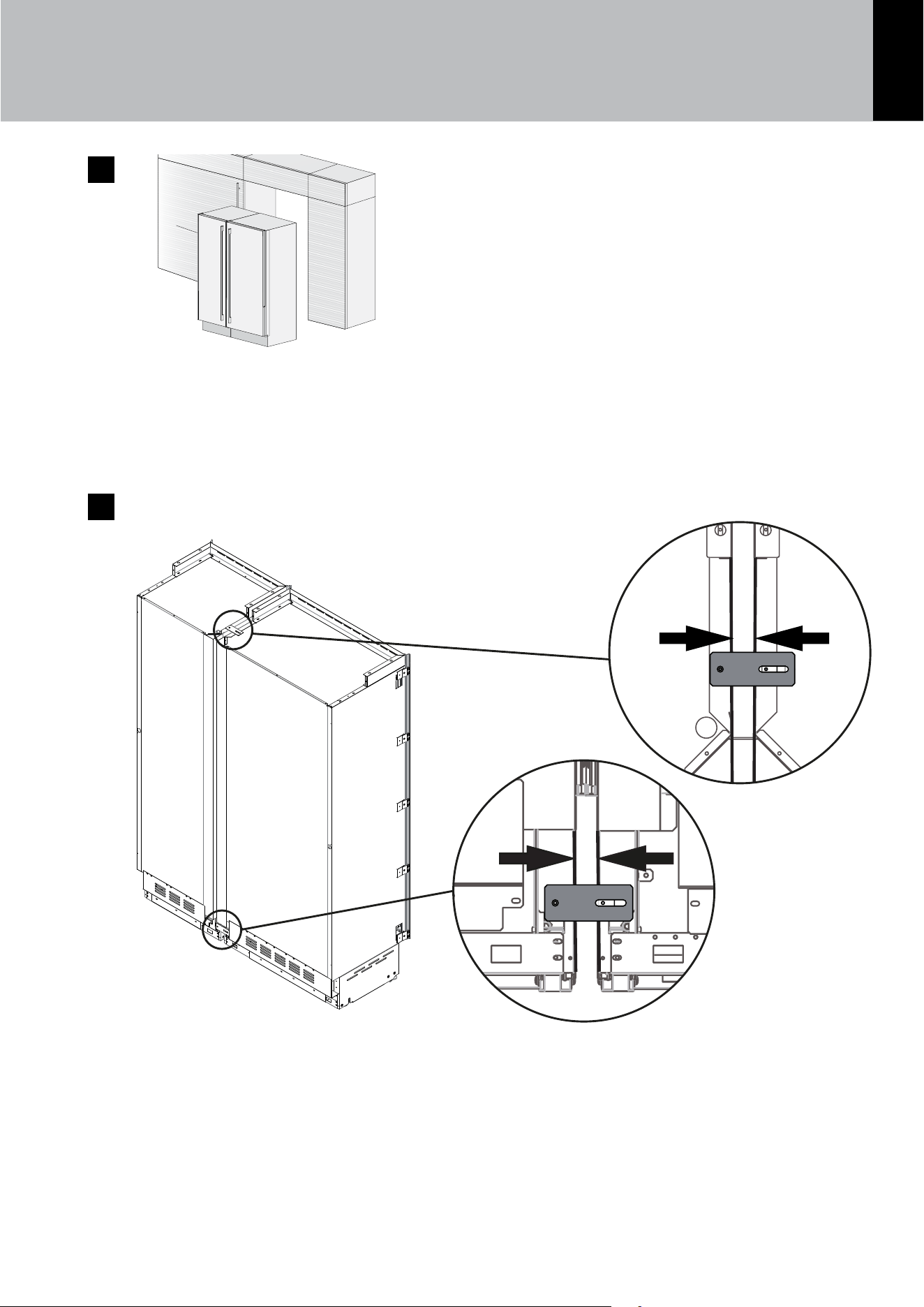
For a built-in installation, to cover gaps between
the appliance and the adjacent cabinets and ax
the appliance to the cabinetry, use the supplied
10 x bracket kit.
Proceed as follows:
> Push the appliance into the installation cutout [ 1 ].
> Always mount front panel on door before
pushing the unit into its final position inside the
cutout or structure.
> Check the leveling of the appliance, and correct
it by adjusting the feet and wheels.
> Secure the appliance to the adjacent cabinets
using the 10 x spacer brackets. [ 2 ].
To make this operation easier, keep the door
open.
> Mount the bracket covers: first insert them
laterally, and then push firmly until you hear a
“click” [ 3 ].
Mounting the side profiles:
Appliance
Wall or furniture
A
B
B
Click!
Click!
A Plastic connecting brackets
B Profile trim cover
6.2 Built-in installation of two or
more appliances
> The central profile is provided with freezer and
wine-cellar columns.
Plastic covering frames are provided for
closing gaps between the appliance and
the adjacent cabinets.
Proceed as follows:
> Position the appliances in front of the installation
area, leaving enough space to work behind them [
1 ].
3
1
2
27
EN
6. INSTALLATION: ALL MODELS
IMPORTANT: the appliances must be level with one another. This can most easily be achieved by
aligning the holes of each appliance's mounting brackets with one another.
> Access the back of the appliances to mount the joining brackets; fix one side of the top, and lower brackets
first to one of the appliances and then to the other [ 1 ] paying attention to the gap as per the table on the
following pages.
1
BOTTOM COMPRESSOR UNITS
C
C
A
B
2
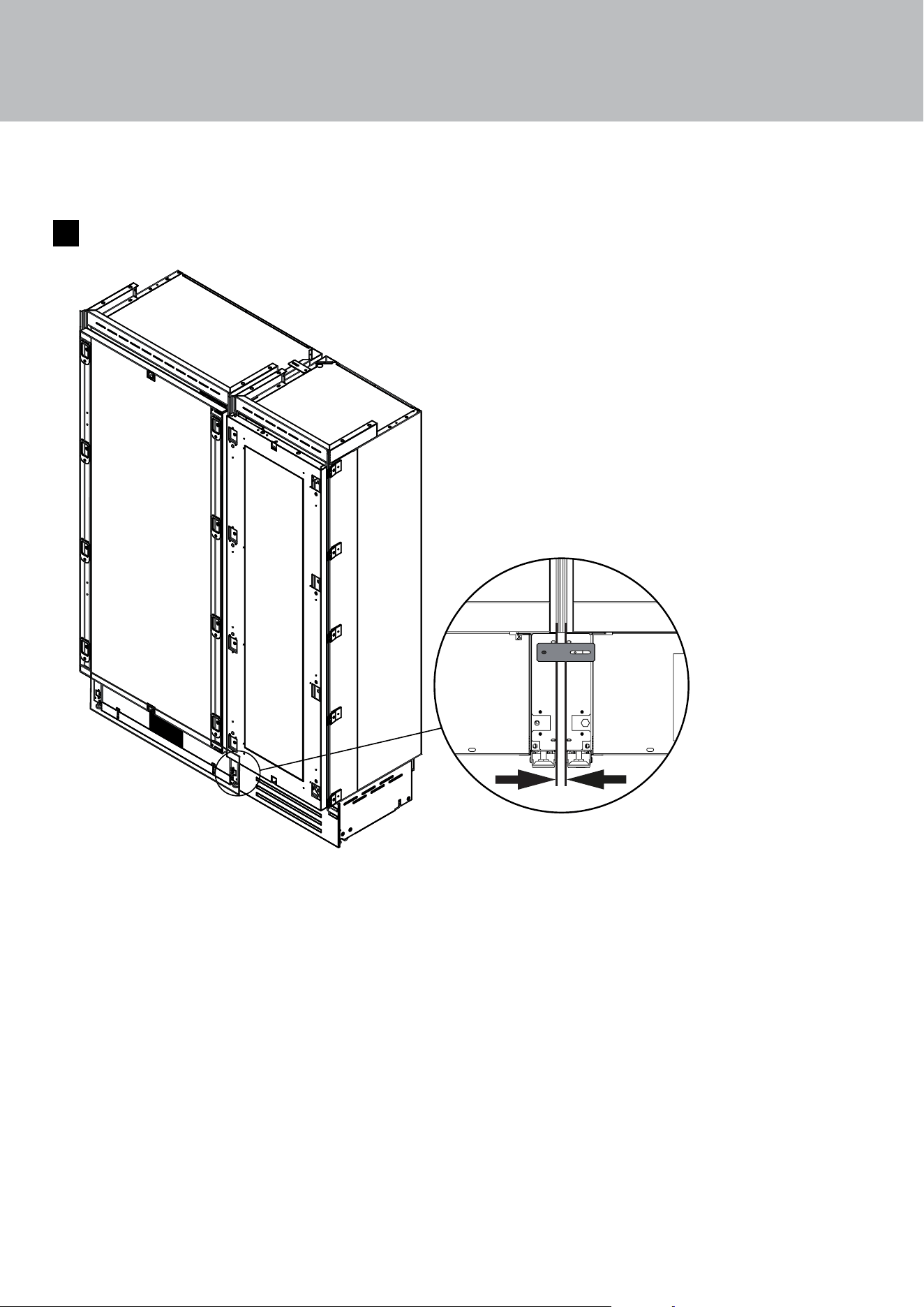
28
6. INSTALLATION: ALL MODELS
Do the same at the lower front section of each
appliance with the provided bracket [ 2 ].
A
B
C
BOTTOM COMPRESSOR UNITS
2
29
EN
6. INSTALLATION: ALL MODELS
Distance between units (A+B)
C
A
18” 24” 30” 36”
B
18” 7/8” (22 mm)
15/16” (23.5
mm)
1” (24.5 mm) 1” (25.5 mm)
24”
15/16” (23.5
mm)
1” (25 mm) 1” (26 mm) 1 1/16” (27 mm)
30” 1” (24.5 mm) 1” (26 mm) 1 1/16” (27 mm) 1 1/8” (28 mm)
36” 1” (25.5 mm) 1 1/16” (27 mm) 1 1/8” (28 mm) 1 1/8” (29 mm)
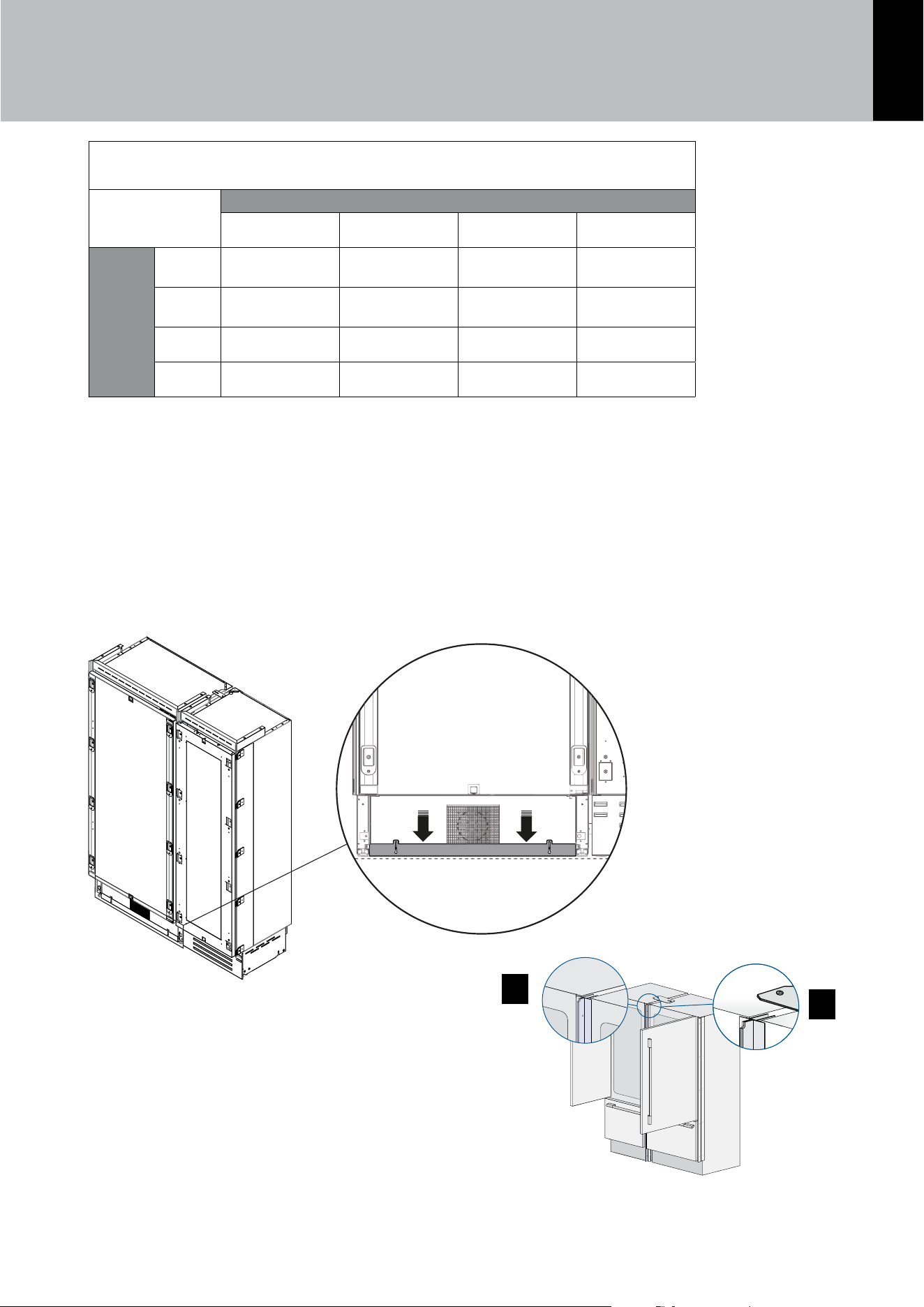
Once the appliances have been adjusted and properly leveled, loosen the two screws holding the sealing
plate in position.
Lower the plate until flush with the floor, and re-tighten the screws. This will ensure optimization of the airflow
through the condenser, which is necessary for proper operation.
This table is a reference for the required space at the back of the units between the appliance bodies when
installing the metal brackets from the joining kit. This space between the bodies will occur naturally when
connecting the units at the front using the supplied plastic mounting brackets. The table is a tool to help you
ensure that the space between the units is consistent from front to back. Example of why this is important:
if the space at the back between the units is wider than the space at the front, the drawers may collide with
each other when fully opened.
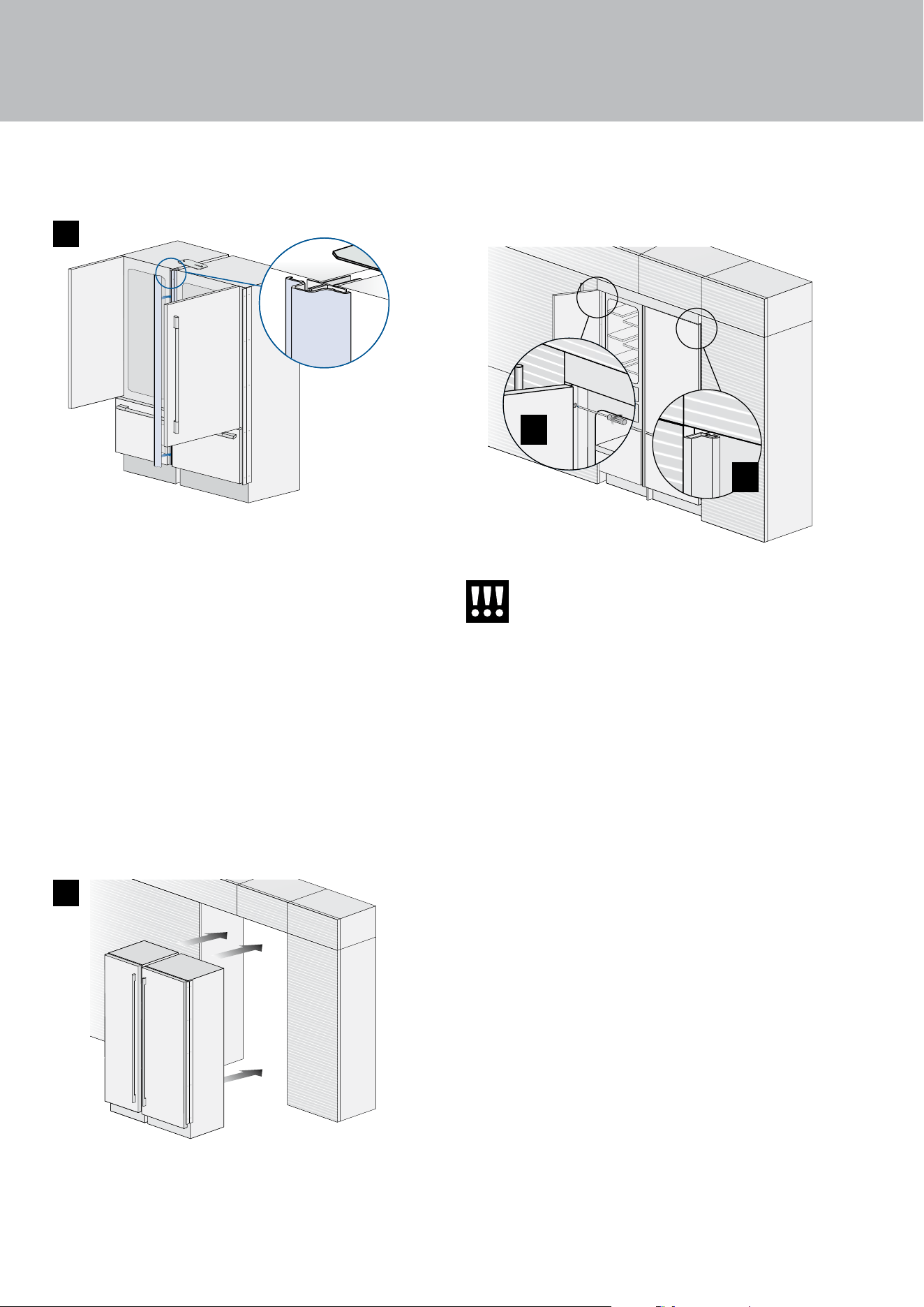
> Next, join them at the front by attaching the plastic
connecting brackets with the supplied screws [ 3 ].
We recommend using two screws for connecting
each bracket; one from each side [ 4 ].
3
4
30
6. INSTALLATION: ALL MODELS
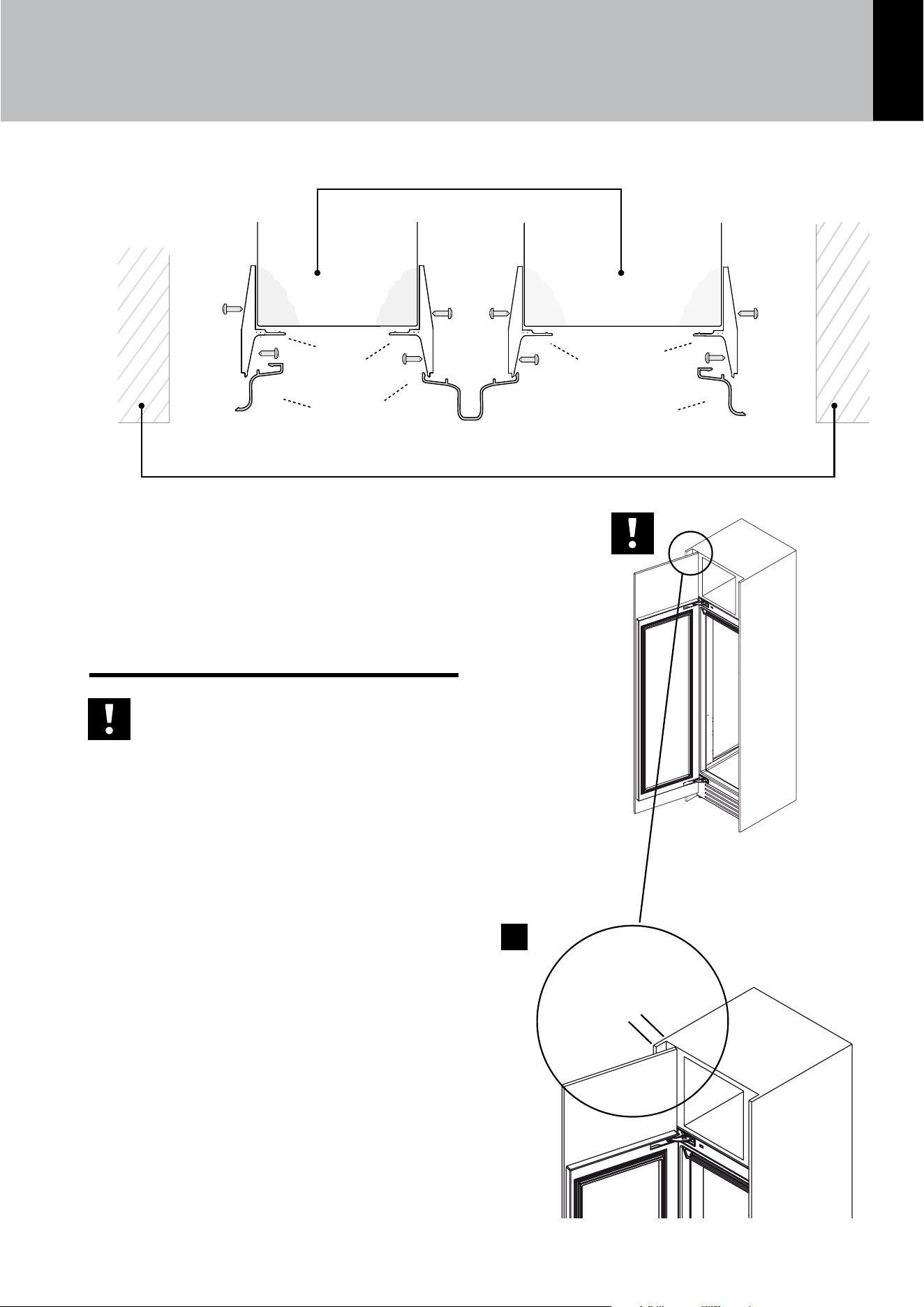
> Finish o by mounting the central profile cover
onto the central profiles by pushing it until you hear
a click [ 5 ].
> Once completed, push the units into their final
position [ 6 ].
Always mount front panels on door before pushing
the unit into its final position inside the cutout or
structure.
> Check the leveling of the appliance, and correct
it by adjusting its feet and wheels.
> Secure the appliance to the adjacent cabinets by
fixing with the supplied brackets on the appliance
[ 7 ]. To make this operation easier, keep the door
open.
> Mount the covering frames onto the profiles; first
insert them laterally, and then push firmly until you
hear a “click” [ 8 ].
Exercise caution, as appliances will be
front-heavy and may tip before they are
secured to the adjacent furniture.
5
6
7
8
7
8
31
EN
Appliance
Wall or furniture
C
A
B
B
A
A
A
Mounting the side and center proles:
A - Plastic mounting/connecting brackets
B - Profile trim cover (side)
C - Profile trim cover (center)
6.3 Maximum cabinet depth
over panel-ready appliance
with single door panel
It is possible that the design of the kitchen and,
in particular, of the cutout where the panel-ready
appliance will be fitted includes a cabinet right
above the refrigerator itself that must be closed
with the same panel mounted on the panel-ready
refrigerator door.
In this case, the depth of the cabinet above the
appliance must not exceed the depth of the
appliance without the door [ 1 ].
This will allow the panel attached to the refrigerator
door to open correctly without interference during
its rotation of up to 100°.
6. INSTALLATION: ALL MODELS
47 (1 ⅞”) + front panel thickness
47 (1 ⅞”) + front panel thickness
47 mm (1 7/8”)
1
32
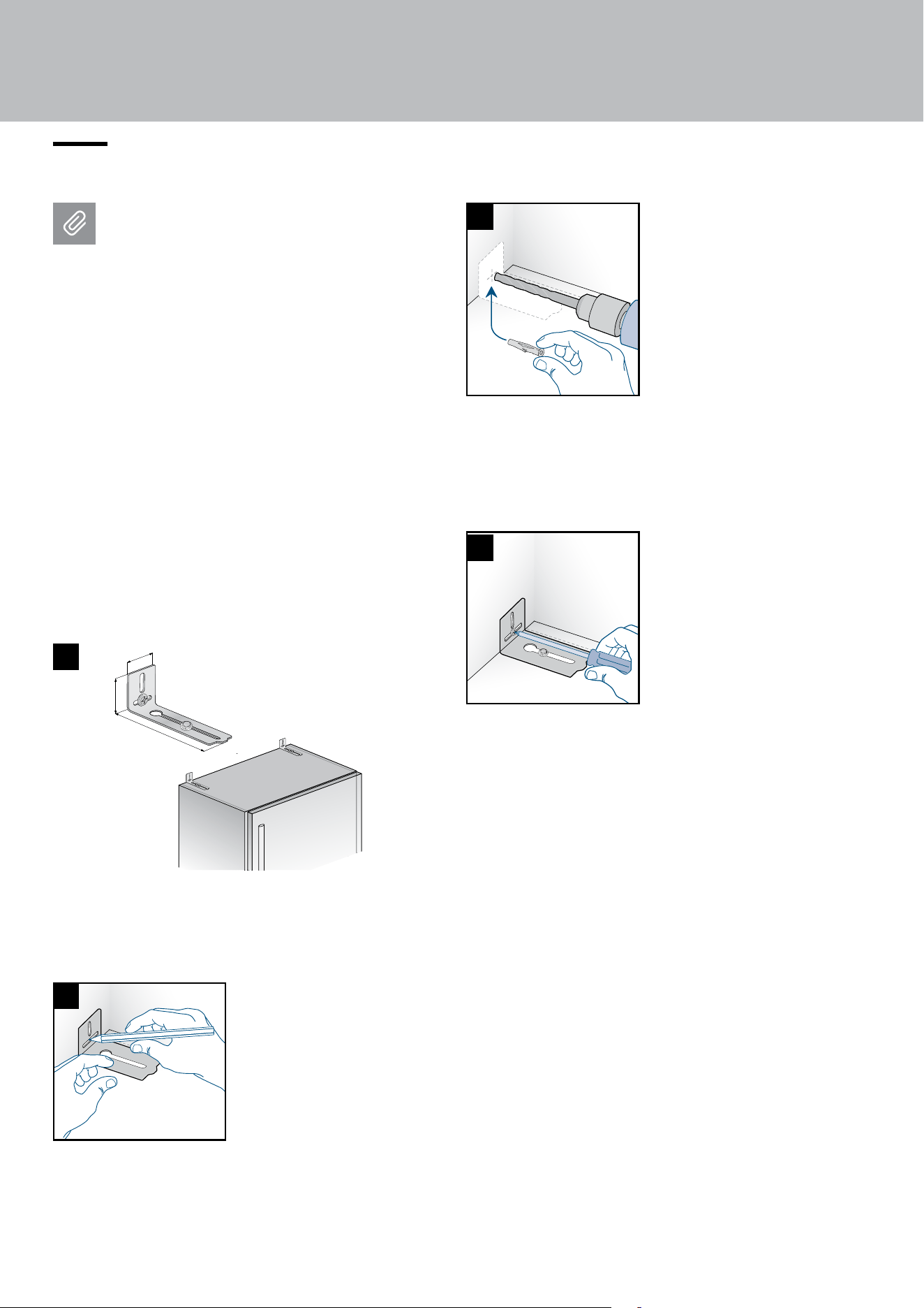
7.1 Anti-tipping safety assembly
If the appliance(s) is not connected through
the side profile trims to secured cabinetry,
you must install the anti-tip brackets to
ensure the product does not fall forward
during use and cause damage or injury.
Failing to secure the appliance(s) securely
will void any warranty claim attributable to
a tipping situation.
Proceed as follows:
> The brackets should be applied as illustrated
using the provided screws. If using the anti-tip
brackets, bolt into wood framing or concrete using
a lag bolt; drywall will not hold the weight of the
appliance.
Place a bracket on the top of the appliance aligning
it with the fixing holes and against the wall [ 1 ].
> Mark the position of the holes on the wall [ 2 ].
7. COMPLETING THE INSTALLATION
> Drill the wall with an 8-mm (3/8”) bit, and insert
the expansion plug [ 3 ].
> Reposition the bracket, and fix it first to the
cabinet and then to the wall [ 4 ].
ALL MODELS
ALL MODELS
2 x
6 x
152 (6”)
59 (
2
3⁄8
”)
45 (1
5⁄8
”)
1
2 x
6 x
152 (6”)
59 (
2
3⁄8
”)
45 (1
5⁄8
”)
1
2
3
4
33
EN
36 ’’ 30 ‘‘ 24 ‘‘ 18 ‘‘
A
33 7/8” (860) 29 1/8” (740) 22” (560) 16 1/8” (410)
B
> 4” (100)
C
3/8” (10)
7.2 Ventilation
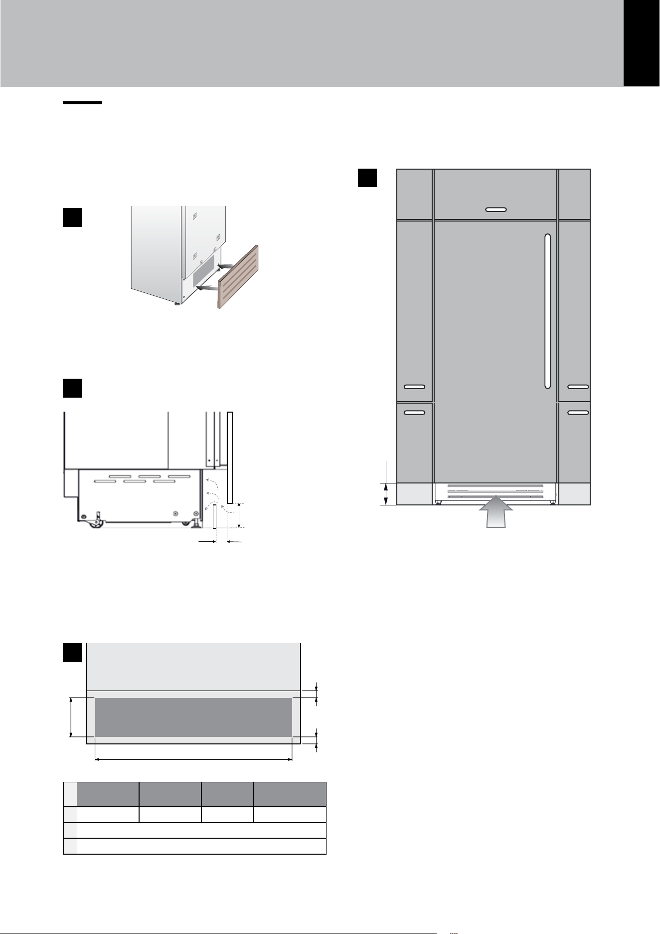
ALL MODELS
A forced-air system assures ventilation through a
grille secured to the unit with magnetic plates,
positioned in the lower front part of the unit [ 1 ].
If the kitchen cabinet includes a kickplate, it must be
placed in such a way as to ensure optimal airflow [ 2 ].
If placing a kickplate dierently from picture [ 2
], the kickplate must have vents/openings with
an area of at least 50% of the area delimited by
dimensions A and B in picture [ 3 ].
The condenser must be cleaned on a regular
basis. In order to clean it, the front grille must be
accessible [ 4 ].
7. COMPLETING THE INSTALLATION
A
B
C
C
100 (4”)
1 ⅞” (50mm)
min 4” (100mm)
2
1
3
4
34
7.3 Post-installation checklist
Check that the front leveling feet have been
properly installed.
Check that the connection to the water system
does not have any leaks and that the shut-o valve
is easily accessible.
Check that the electrical connection is correctly
installed and that the socket and/or breaker are
easily accessible.
Check that the appliance is perfectly aligned
with adjacent structures.
Check that all adhesive tape and external or
internal temporary protective devices have been
removed.
Check that the doors close perfectly and that
the drawers and shelves slide smoothly.
7.4 Start-up
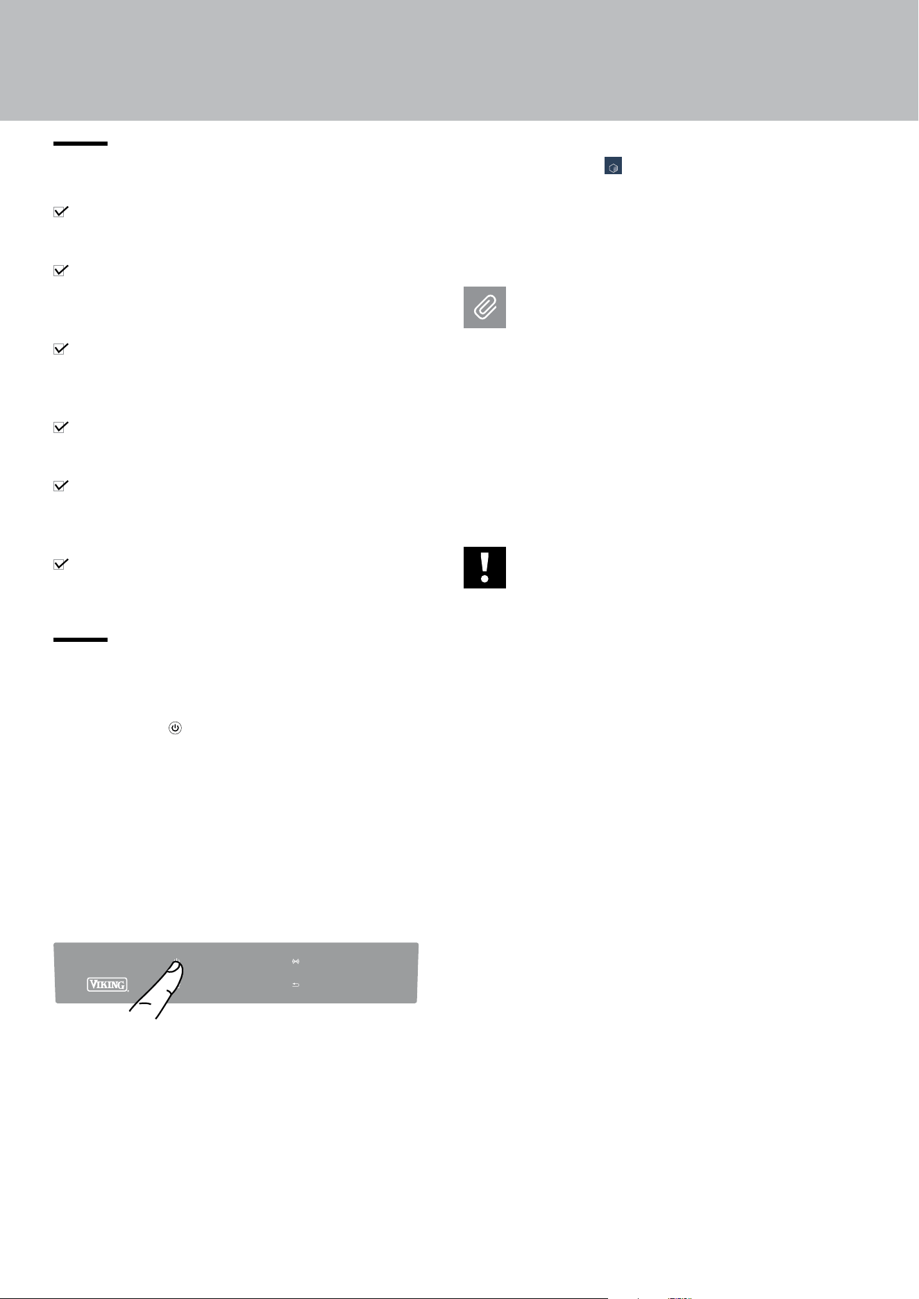
>To turn all the appliance compartments on,
press the Unit button for three seconds. The
display will show the message “Initial test” for
approximately two minutes. After this phase, the
compressors will start up and remain on until the set
temperatures for the compartment are reached.
> If the appliance is provided with an Ice Maker,
make sure that the water filter cartridge is
installed prior to switching it on (unless water
supply source is already filtered by other means
such as reverse osmosis).
> Purge air from the water lines by performing
the ‘Manual Clean’ function from the Menu-
>Functions->Water Filter options. You may need
to complete this sequence several times until you
stop hearing air sputtering from the ice maker fill
tube (Refer to your Use & Care Manual).
> Once you are satisfied that the system has been
purged of air, switch the Ice Maker on in the ice
maker menu item
ICE MAKER
WATER FILTER
SYSTEM CLEANINGWATER DISPENSER
of the appliance functions.
Please refer to the Use & Care Manual for more
details.
> For further information on operating the
appliance, please refer to the User Manual.
If messages such as Fridge too warm,
Freezer too warm appear at the first start,
or if sound signals are activated, this
indicates that the appliance has already
previously started the cooling process.
If this is the case, deactivate any possible
acoustic signals by pressing the Alarm
button, close the door, and wait until the
set temperature is reached. Allow the
appliance to run/cool for at least 24 hours.
If the set temperatures have not been
reached within 24 hours, contact service.
It is necessary to let the unit reach the correct
temperature before foods are stored inside.
Viking is constantly researching new ways
to improve the features and the design of its
products; therefore models are often upgraded
and revised.
7. COMPLETING THE INSTALLATION

Viking Range, LLC
111 Front Street
Greenwood, Mississippi 38930 USA (662) 455-1200
For product information, call 1-888-(845-4641)
or visit the our web site at vikingrange.com
080725