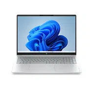
Maintenance and Service Guide
HP OmniBook 5 16 inch Laptop Next Gen
AI PC: Model Numbers: 16-bm0xxx and 16-
bp0xxx
HP OmniBook 5 16 inch Laptop AI
PC: Model Numbers: 16-bn1xxx and 16-
cm0xxx
HP OmniBook 5 16 inch Laptop PC: Model
Numbers: 16-bn0xxx and 16-br0xxx
SUMMARY
This guide provides maintenance information about such topics as spare parts, removal and replacement of parts,
security, and backing up.

Legal information
© Copyright 2026 HP Development
Company, L.P.
AMD, Ryzen, and Radeon are trademarks
of Advanced Micro Devices, Inc. DTS:X
is a registered trademark of DTS, Inc.
Bluetooth is a trademark owned by its
proprietor and used by HP Inc. under license.
Chromebook, ChromeOS and Google Drive
are trademarks of Google LLC. Intel, Arc,
Core, Iris, and Thunderbolt are trademarks
of Intel Corporation or its subsidiaries in
the U.S. and/or other countries. Linux is a
registered trademark of Linus Torvalds in
the U.S. and other countries. Microsoft and
Windows are either registered trademarks or
trademarks of Microsoft Corporation in the
United States and/or other countries. NVIDIA
is a trademark or registered trademark of
NVIDIA Corporation in the U.S. and other
countries. SD is a trademark or registered
trademark of SD-3C LLC. USB4, USB Type-
C, and USB-C port logos are registered
trademarks of USB Implementers Forum.
DisplayPort and the DisplayPort logo are
trademarks owned by the Video Electronics
Standards Association (VESA) in the United
States and other countries. Miracast and Wi-
Fi are registered trademarks of Wi-Fi Alliance.
The information contained herein is subject to
change without notice. The only warranties
for HP products and services are set
forth in the express warranty statements
accompanying such products and services.
Nothing herein should be construed as
constituting an additional warranty. HP shall
not be liable for technical or editorial errors or
omissions contained herein.
Second Edition: May 2026
First Edition: January 2026
Document Part Number: P74414-002
Product notice
This guide describes features that are
common to most models. Some features may
not be available on your computer.
Not all features are available in all editions or
versions of Windows. Systems may require
upgraded and/or separately purchased
hardware, drivers, software or BIOS update to
take full advantage of Windows functionality.
Windows is automatically updated, which
is always enabled. High-speed internet
and Microsoft account required. ISP fees
may apply and additional requirements
may apply over time for updates. See
http://www.microsoft.com. If your product
ships with Windows in S Mode: Windows
in S Mode works exclusively with apps from
the Microsoft Store within Windows. Certain
default settings, features, and apps cannot
be changed. Some accessories and apps
that are compatible with Windows may not
work (including some antivirus, PDF writers,
driver utilities, and accessibility apps), and
performance may vary, even if you switch
out of S Mode. If you switch to Windows, you
cannot switch back to S Mode. Learn more at
Windows.com/SmodeFAQ.
To access the latest user guides, go to
http://www.hp.com/support, and follow the
instructions to
nd your product. Then select
Setup & User Guides.
Software terms
By installing, copying, downloading, or
otherwise using any software product
preinstalled on this computer, you agree
to be bound by the terms of the HP End
User License Agreement (EULA). If you do
not accept these license terms, your sole
remedy is to return the entire unused product
(hardware and software) within 14 days for a
full refund subject to the refund policy of your
seller.
For any further information or to request a full
refund of the price of the computer, please
contact your seller.

Safety warning notice
Reduce the possibility of heat-related injuries or of overheating the computer by following the practices
described.
WARNING! To reduce the possibility of heat-related injuries or of overheating the mobile computer, do
not place the mobile computer directly on your lap or obstruct the computer air vents. Use the mobile
computer only on a hard, at surface. Do not allow another hard surface, such as an adjoining optional
printer; or a soft surface, such as pillows, rugs, or clothing, to block airow. Also, do not allow the AC
adapter to contact the skin or a soft surface, such as pillows, rugs or clothing, during operation. The
computer and AC adapter provided by HP comply with the user-accessible surface temperature limits
dened by applicable safety standards.
iii

Important notice about Customer Self-Repair parts
Your computer includes Customer Self-Repair parts and parts that should be accessed only by an
authorized service provider.
IMPORTANT: See Removal and replacement procedures for Customer Self-Repair parts on page 30
for details.
Accessing parts described in Removal and replacement procedures for authorized service provider
parts on page 41 can damage the computer or void your warranty.
iv Important notice about Customer Self-Repair parts

Table of contents
1 Product description............................................................................................................................................................................. 1
2 Getting to know your computer....................................................................................................................................................... 5
Right side .......................................................................................................................................................................................................................................................5
Left side...........................................................................................................................................................................................................................................................6
Display .............................................................................................................................................................................................................................................................7
Low blue light mode (select products only) .............................................................................................................................................................7
Wake-on-voice (select products only)..........................................................................................................................................................................7
Keyboard area................................................................................................................................................................................................................................9
Touchpad settings and components................................................................................................................................................................9
Touchpad settings...............................................................................................................................................................................................9
Touchpad components....................................................................................................................................................................................9
Lights .....................................................................................................................................................................................................................................10
Special keys......................................................................................................................................................................................................................12
Bottom .............................................................................................................................................................................................................................................13
Labels................................................................................................................................................................................................................................................14
3 Illustrated parts catalog..................................................................................................................................................................15
Computer major components ..................................................................................................................................................................................................15
Display assembly subcomponents......................................................................................................................................................................................19
Miscellaneous parts .........................................................................................................................................................................................................................20
4 Removal and replacement procedures preliminary requirements .................................................................................22
Tools required.........................................................................................................................................................................................................................................22
Service considerations..................................................................................................................................................................................................................22
Plastic parts.................................................................................................................................................................................................................................22
Cables and connectors ......................................................................................................................................................................................................22
Drive handling.............................................................................................................................................................................................................................22
Electrostatic discharge information.....................................................................................................................................................................................23
Generating static electricity...........................................................................................................................................................................................23
Preventing electrostatic damage to equipment .............................................................................................................................................24
Personal grounding methods and equipment ..................................................................................................................................................24
Grounding the work area...................................................................................................................................................................................................25
Recommended materials and equipment...........................................................................................................................................................25
Cleaning your computer ................................................................................................................................................................................................................26
Enabling HP Easy Clean (select products only)................................................................................................................................................26
Removing dirt and debris from your computer................................................................................................................................................26
Cleaning your computer with a disinfectant......................................................................................................................................................27
Caring for wood veneer (select products only)................................................................................................................................................28
Packaging and transporting guidelines.............................................................................................................................................................................28
Accessing support information...............................................................................................................................................................................................28
v

5 Removal and replacement procedures for Customer Self-Repair parts......................................................................30
Component replacement procedures................................................................................................................................................................................30
Preparation for disassembly..........................................................................................................................................................................................30
Bottom cover ..............................................................................................................................................................................................................................30
Battery .............................................................................................................................................................................................................................................33
Removing and reinstalling the same battery .........................................................................................................................................33
Installing a new battery ...........................................................................................................................................................................................35
6 Removal and replacement procedures for authorized service provider parts..........................................................41
Component replacement procedures................................................................................................................................................................................41
Speakers ........................................................................................................................................................................................................................................41
Transition board........................................................................................................................................................................................................................42
OLED power management board...............................................................................................................................................................................43
Solid-state drive........................................................................................................................................................................................................................44
WLAN module.............................................................................................................................................................................................................................45
Fan.......................................................................................................................................................................................................................................................47
USB board .....................................................................................................................................................................................................................................48
Touchpad........................................................................................................................................................................................................................................49
Heat sink.........................................................................................................................................................................................................................................51
System board .............................................................................................................................................................................................................................52
Display assembly ....................................................................................................................................................................................................................56
Keyboard with top cover.....................................................................................................................................................................................................62
7 Troubleshooting guide......................................................................................................................................................................64
Resources.................................................................................................................................................................................................................................................64
General troubleshooting steps.................................................................................................................................................................................................65
Identify the issue......................................................................................................................................................................................................................65
1. Understand the issue..........................................................................................................................................................................................66
Startup sequence............................................................................................................................................................................................66
Failure classication......................................................................................................................................................................................66
2. Examine the environment................................................................................................................................................................................68
3. Perform a visual inspection of hardware.............................................................................................................................................68
4. Update BIOS and drivers..................................................................................................................................................................................69
Manually updating BIOS and drivers................................................................................................................................................69
Remotely deploying the BIOS and drivers....................................................................................................................................69
Analyze the issue.....................................................................................................................................................................................................................69
5. Remove or uninstall recently added hardware, software .......................................................................................................69
6. HP Hardware Diagnostics and Tools.......................................................................................................................................................70
HP PC Hardware Diagnostics UEFI.....................................................................................................................................................70
HP BIOS Conguration Utility (BCU)..................................................................................................................................................71
HP Image Diagnostic Tool..........................................................................................................................................................................72
HP Thermal Monitor........................................................................................................................................................................................72
Non-HP diagnostics tools..........................................................................................................................................................................72
7. Status lights, blinking light codes, troubleshooting lights, and POST error messages...................................72
Status lights..........................................................................................................................................................................................................72
Blinking light codes.........................................................................................................................................................................................73
POST error messages..................................................................................................................................................................................74
Resolve the issue.....................................................................................................................................................................................................................75
vi

8. Hard reset.....................................................................................................................................................................................................................75
9. Soft reset (Default Settings)..........................................................................................................................................................................76
10. Reseat cables and connections .............................................................................................................................................................76
11. Test with minimum conguration ...........................................................................................................................................................77
Essential hardware conguration.......................................................................................................................................................77
Safe mode..............................................................................................................................................................................................................78
12. Test with veried working conguration (hardware or operating system)............................................................. 78
13. Replace the system board...........................................................................................................................................................................78
Verify solution.............................................................................................................................................................................................................................79
Helpful Hints............................................................................................................................................................................................................................................79
At startup .......................................................................................................................................................................................................................................80
During operation ......................................................................................................................................................................................................................80
Consulting with HP Service .............................................................................................................................................................................................81
Common issues and possible solutions...........................................................................................................................................................................81
Power-on issues........................................................................................................................................................................................................................81
No power.............................................................................................................................................................................................................................81
Intermittent power-on, shutdown, restart..................................................................................................................................................83
AC adapter issue..........................................................................................................................................................................................................84
Battery not recognized, not charging...........................................................................................................................................................85
Battery discharges too fast.................................................................................................................................................................................88
Burnt smell ........................................................................................................................................................................................................................88
POST..................................................................................................................................................................................................................................................89
No video (with power)................................................................................................................................................................................................89
Blinking lights...................................................................................................................................................................................................................90
Diagnostic error messages.................................................................................................................................................................................91
BIOS password..............................................................................................................................................................................................................91
Performance (OS)....................................................................................................................................................................................................................92
Intermittent shutdown..............................................................................................................................................................................................92
Blue screen.......................................................................................................................................................................................................................93
Freeze at Windows Logo (hang or lockup)................................................................................................................................................95
Electromagnetic Interference (EMI)...............................................................................................................................................................96
No wake up........................................................................................................................................................................................................................97
Unresponsive..................................................................................................................................................................................................................98
Slow performance.......................................................................................................................................................................................................99
HP Smart Adapter warning message..........................................................................................................................................................99
Incorrect time and date........................................................................................................................................................................................100
Display...........................................................................................................................................................................................................................................101
Display anomalies....................................................................................................................................................................................................101
Symptom..............................................................................................................................................................................................................101
Quick check .......................................................................................................................................................................................................102
HP PC Hardware Diagnostics (UEFI) for video test.............................................................................................................102
Display assembly diagram ....................................................................................................................................................................103
Dead pixel........................................................................................................................................................................................................................103
No video (internal).....................................................................................................................................................................................................103
No video (external) ...................................................................................................................................................................................................104
DisplayPort/VGA........................................................................................................................................................................................................104
HDMI....................................................................................................................................................................................................................................104
No or bad external video via docking........................................................................................................................................................105
vii

Incorrect or missing color/distorted image..........................................................................................................................................106
Touch screen................................................................................................................................................................................................................107
I/O devices..................................................................................................................................................................................................................................108
Keyboard..........................................................................................................................................................................................................................108
Keyboard pointing stick (select products only)..................................................................................................................................109
Keyboard backlight..................................................................................................................................................................................................110
Touchpad.........................................................................................................................................................................................................................110
Network connectivity (RJ-45 jack)...............................................................................................................................................................111
Network connectivity wireless (WLAN)....................................................................................................................................................111
WWAN................................................................................................................................................................................................................................112
USB.......................................................................................................................................................................................................................................112
Smart card reader....................................................................................................................................................................................................113
Speaker, headphone - audio issues............................................................................................................................................................114
Thunderbolt (TB).........................................................................................................................................................................................................116
Storage.........................................................................................................................................................................................................................................116
Hard drive or SSD not recognized...............................................................................................................................................................117
No boot to operating system (no read-write error).........................................................................................................................118
Read-write error.........................................................................................................................................................................................................119
Slow performance....................................................................................................................................................................................................119
Blue screen (BSOD) error...................................................................................................................................................................................120
Noisy hard drive..........................................................................................................................................................................................................120
Mechanical................................................................................................................................................................................................................................121
Noise (sound) ...............................................................................................................................................................................................................121
Fan runs constantly.................................................................................................................................................................................................122
Thermal shutdown (hot) .......................................................................................................................................................................................123
Additional information..................................................................................................................................................................................................................123
Acronyms....................................................................................................................................................................................................................................124
Blinking lights and startup error codes ...............................................................................................................................................................124
Processor not executing code .......................................................................................................................................................................125
BIOS recovery code unable to nd valid BIOS recovery image...........................................................................................125
Memory module error ...........................................................................................................................................................................................125
Graphics Controller Error (No Controller)..............................................................................................................................................126
Failure System Board Error...............................................................................................................................................................................126
Intel Trusted Execution Technology (TXT) Error .................................................................................................................................126
Sure Start unable to nd valid BIOS Boot Block image ..............................................................................................................126
Sure Start has identied a problem (Manual Recovery Policy Set)...................................................................................126
POST error messages and user actions............................................................................................................................................................127
Routine maintenance for performance improvement............................................................................................................................128
Common blue screen error messages...............................................................................................................................................................129
Error message list ....................................................................................................................................................................................................129
Bug check symbolic names..............................................................................................................................................................................129
Microsoft general troubleshooting of Windows bug check codes....................................................................................129
Use Windows Debugging Tool ....................................................................................................................................................................................130
Windows Software Development Kit (SDK)..........................................................................................................................................130
Display issue: pixel anomalies....................................................................................................................................................................................134
Cable management............................................................................................................................................................................................................135
Connector types ...................................................................................................................................................................................................................136
Flex cable.........................................................................................................................................................................................................................136
viii

Horizontal cable insertion..................................................................................................................................................................................137
Multiple-pin horizontal connector (LVDS cable to display panel)........................................................................................137
Multiple-pin vertical connector (LVDS cable to system board) .............................................................................................137
8 Using Setup Utility (BIOS).............................................................................................................................................................. 139
Starting Setup Utility (BIOS).....................................................................................................................................................................................................139
Updating Setup Utility (BIOS)...................................................................................................................................................................................................139
Determining the BIOS version....................................................................................................................................................................................139
Preparing for a BIOS update........................................................................................................................................................................................140
Downloading a BIOS update............................................................................................................................................................................140
Installing a BIOS update ......................................................................................................................................................................................141
9 Computer Setup (BIOS), TPM, and HP Sure Start................................................................................................................142
Using Computer Setup ................................................................................................................................................................................................................142
Navigating and selecting in Computer Setup ...............................................................................................................................................142
Restoring factory settings in Computer Setup.............................................................................................................................................142
Updating the BIOS ...............................................................................................................................................................................................................143
Determining the BIOS version ........................................................................................................................................................................143
Preparing for a BIOS update............................................................................................................................................................................143
Downloading a BIOS update ................................................................................................................................................................144
Installing a BIOS update...........................................................................................................................................................................144
Changing the boot order using the f9 prompt ..............................................................................................................................................145
TPM BIOS settings (select products only) ...................................................................................................................................................................145
Using HP Sure Start (select products only)..................................................................................................................................................................145
10 Backing up, resetting, and recovering .................................................................................................................................. 146
Backing up .............................................................................................................................................................................................................................................146
Resetting.................................................................................................................................................................................................................................................146
Recovering.............................................................................................................................................................................................................................................146
Installing the Chromebook Recovery Utility.....................................................................................................................................................147
Creating recovery media................................................................................................................................................................................................147
Recovering the Chrome operating system ......................................................................................................................................................147
Setting up your computer after a reset or recovery.............................................................................................................................................148
Erase and reformat the recovery media........................................................................................................................................................................148
11 Backing up, restoring, and recovering.................................................................................................................................. 149
Backing up information and creating recovery media........................................................................................................................................149
Using Windows tools for backing up......................................................................................................................................................................149
Using the HP Cloud Recovery Download Tool to create a recovery USB ash drive (select products
only) .................................................................................................................................................................................................................................................149
Restoring and recovering your system ...........................................................................................................................................................................149
Creating a system restore ............................................................................................................................................................................................150
Restoring and recovery methods............................................................................................................................................................................150
Recovering using the HP Recovery USB ash drive .................................................................................................................................150
Changing the computer boot order .......................................................................................................................................................................151
Using HP Sure Recover (select products only)..............................................................................................................................................151
ix

12 Using HP PC Hardware Diagnostics ...................................................................................................................................... 152
Using HP PC Hardware Diagnostics Windows (select products only)....................................................................................................152
Using an HP PC Hardware Diagnostics Windows hardware failure ID code..........................................................................152
Accessing HP PC Hardware Diagnostics Windows..................................................................................................................................152
Accessing HP PC Hardware Diagnostics Windows from HP Support Assistant (select products
only)......................................................................................................................................................................................................................................152
Accessing HP PC Hardware Diagnostics Windows from the Start menu (select products only).............153
Downloading HP PC Hardware Diagnostics Windows............................................................................................................................153
Downloading the latest HP PC Hardware Diagnostics Windows version from HP...............................................153
Downloading the HP PC Hardware Diagnostics Windows from the Microsoft Store.........................................153
Downloading HP Hardware Diagnostics Windows by product name or number (select products
only)......................................................................................................................................................................................................................................154
Installing HP PC Hardware Diagnostics Windows......................................................................................................................................154
Using HP PC Hardware Diagnostics UEFI......................................................................................................................................................................154
Using an HP PC Hardware Diagnostics UEFI hardware failure ID code.....................................................................................154
Starting HP PC Hardware Diagnostics UEFI....................................................................................................................................................154
Starting HP PC Hardware Diagnostics UEFI through HP Hotkey Support software (select products
only) .................................................................................................................................................................................................................................................155
Downloading HP PC Hardware Diagnostics UEFI to a USB ash drive ......................................................................................155
Downloading the latest HP PC Hardware Diagnostics UEFI version................................................................................156
Downloading HP PC Hardware Diagnostics UEFI by product name or number (select products
only)......................................................................................................................................................................................................................................156
Using Remote HP PC Hardware Diagnostics UEFI settings (select products only)......................................................................156
Downloading Remote HP PC Hardware Diagnostics UEFI...................................................................................................................156
Downloading the latest Remote HP PC Hardware Diagnostics UEFI version............................................................156
Downloading Remote HP PC Hardware Diagnostics UEFI by product name or number..................................157
Customizing Remote HP PC Hardware Diagnostics UEFI settings...............................................................................................157
13 Specications................................................................................................................................................................................ 158
Computer specications...........................................................................................................................................................................................................158
Display specications..................................................................................................................................................................................................................159
Solid-state drive specications............................................................................................................................................................................................159
14 Power cord set requirements................................................................................................................................................... 161
Requirements for all countries ..............................................................................................................................................................................................161
Requirements for specic countries and regions..................................................................................................................................................161
15 Swelling or deformation of notebook battery.................................................................................................................... 164
Swollen notebook batteries.....................................................................................................................................................................................................164
Swollen battery is not a safety issue.....................................................................................................................................................................164
Discontinue using a swollen battery .....................................................................................................................................................................164
Replace a swollen battery .............................................................................................................................................................................................164
Minimize battery swelling...........................................................................................................................................................................................................164
Adaptive Battery Optimizer (consumer notebooks).................................................................................................................................165
HP Battery Health Manager (commercial notebooks)............................................................................................................................165
16 Recycling.......................................................................................................................................................................................... 166
x


Product description1
This table provides detailed product information.
NOTE: For the latest specications related to your computer, go to http://www.hp.com/support and
follow the instructions to nd your product. Select Specications & Accessories, select Product
information, and then select the specications link.
Table 1-1 Product components and their descriptions
Category Description
Product Name HP OmniBook 5 16 inch Laptop Next Gen AI PC
AMD® model numbers: 16-bp0xxx
Intel® model numbers: 16-bm0xxx
HP OmniBook 5 16 inch Laptop AI PC
AMD model numbers: 16-br0xxx
Intel model numbers: 16-bn1xxx
HP OmniBook 5 16 inch Laptop PC
AMD model numbers: 16-cm0xxx
Intel model numbers: 16-bn0xxx
Processors
AMD Ryzen™ processors
AMD Ryzen AI 9 465
AMD Ryzen AI 7 445
AMD Ryzen AI 5 430
AMD Ryzen AI 5 330
AMD Ryzen 7 250
AMD Ryzen 5 230
Intel Core™ processors
Intel Core Ultra 9 processor
Intel Core Ultra 7 processor
Intel Core Ultra 5 processor
Intel Core i7 processor
Intel Core i5 processor
Graphics Intel graphics
Intel Arc™ Graphics
Intel Graphics
Intel Iris® Xe
Product description 1

Table 1-1 Product components and their descriptions (continued)
Category Description
Intel UHD Graphics
Supports HD decode, DX12, and HDMI
AMD graphics
AMD Radeon™ 840M
AMD Radeon 780M
AMD Radeon 760M
AMD Radeon Integrated Graphics
Display 40.6 cm (16 in), narrow bezel, widescreen ultra extended graphics array (WUXGA)
2.8K (2880 × 1800), antiglare, OLED, at (3.2 mm), 45% NTSC, embedded DisplayPort™ (eDP) 1.5, 500 nits,
120 Hz (variable rate refresh [VRR])
Full high-denition (FHD) (1920 × 1200), touchscreen, antiglare, OLED, at (3.2 mm), 45% NTSC,
embedded DisplayPort (eDP) 1.2, 300 nits, 60 Hz (variable rate refresh [VRR])
Full high-denition (FHD) (1920 × 1200), non-touchscreen, antiglare, OLED, at (3.2 mm), 45% NTSC,
embedded DisplayPort (eDP) 1.2, 300 nits, 60 Hz (variable rate refresh [VRR])
Organic light-emitting diode (OLED)
Low-voltage differential signaling (LVDS)
HD
Touch-on panel (TOP)
Microsoft HDR streaming capable
Memory One memory module supporting up to 16 or 32 GB of RAM
DDR5-7500 dual-channel support
Low-power double data rate (LPDDR)
Supports the following congurations:
● 32 GB (32 × 1)
● 16 GB (16 × 1)
Primary storage PCIe, (Non-Volatile Memory Express) NVMe, M.2 2280 solid-state drives (SSDs)
● 1 TB, PCIe, triple layer cell (TLC)
● 512 GB, PCIe, TLC
Audio and video Audio brand: HP Audio
Support for DTS:X® Ultra
HP FHD Camera: indicator LED, USB 2.0, f2.0, high dynamic range (HDR)
720p by 30 frames per second
Dual-array digital microphone with appropriate software: beam forming, echo cancellation, noise
suppression
Camera privacy cover
Wireless Wireless Local Area Network (WLAN)
2 Chapter 1 Product description

Table 1-1 Product components and their descriptions (continued)
Category Description
Intel Wi-Fi® 7 R2 Be211 + Bluetooth® 6 multiple input, multiple output (MU-MIMO), supporting gigabit le
transfer speeds
Realtek Wi-Fi 7 + Bluetooth 6 WLAN
Realtek 8852BE-VT Wi-Fi 6 Bluetooth 5.4 WLAN
Compatible with Miracast® devices
Ports Hot plug/unplug and autodetect for correct output to wide-aspect vs. standard aspect video
HDMI v2.1 supporting: up to 4096 × 2160 @ 60 Hz with HDCP 2.2
Audio-out (headphone)/audio-in (microphone) combo jack
USB 3.2 Gen 2 Type C® with Thunderbolt™ Gen 4 technology (left side)
USB 3.2 Gen 2 Type A (supports HP Sleep & Charge; right side)
USB 3.2 Gen 1 Type A (supports HP Sleep & Charge; left side)
USB4® Type-C Thunderbolt 4, supports:
- DisplayPort 1.4 out up to 8 K @ 60 Hz and HDMI 2.1 out with adapter
- Power delivery (100 W input [20 V @ 5A and 20 V @ 3.25A])
- Data transfer
- HDMI 2.1 output up to 8 K @ 60 Hz with HDCP 2.3 with adapter capable of HDMI 2.1
- HP Sleep & Charge
Keyboard/pointing
devices
Keyboard
Full size, backlit, 3-coat paint, island style
Touchpad
Multitouch gestures enabled
Precision touchpad support
Support for Modern Trackpad Gestures
Taps enabled as default
Power requirements Battery
4 cell, 68 Whr, polymer, HP Long Life
HP Fast Charge Technology
Smart AC adapters
65 W, USB Type-C®
Power cord
C5, 2 m (6.6 ft)
Non-Power Factor Correction (nPFC) or Power Factor Correction (PFC)
Security Supports rmware-based Trusted Platform Module (TPM) 2.0
Microphone mute
Product description 3

Table 1-1 Product components and their descriptions (continued)
Category Description
Camera privacy cover
Operating system Windows® 11 Home 64 NextGen Premium
Windows 11 Home 64 NextGen Standard
Windows 11 Pro 64 NextGen Premium
Windows 11 Pro 64 NextGen Standard
Windows 11 Home 64 NextGen Premium Single Language Africa Market PPP
Windows 11 Home 64 NextGen Standard Single Language Africa Market PPP
Windows 11 Home 64 NextGen Premium Single Language APAC EM PPP
Windows 11 Home 64 NextGen Standard Single Language APAC EM PPP
Windows 11 Home 64 NextGen Premium Chinese Market CPPP
Windows 11 Home 64 NextGen Standard Chinese Market CPPP
Windows 11 Home 64 NextGen Premium Single Language India Market PPP
Windows 11 Home 64 NextGen Standard Single Language India Market PPP
Windows 11 Home 64 NextGen Premium Single Language Indonesia Market PPP
Windows 11 Home 64 NextGen Standard Single Language Indonesia Market PPP
Serviceability End user replaceable parts
AC adapter
Bottom cover
Battery
4 Chapter 1 Product description
Getting to know your computer2
Your computer features top-rated components. This chapter provides details about your components,
where they are located, and how they work.
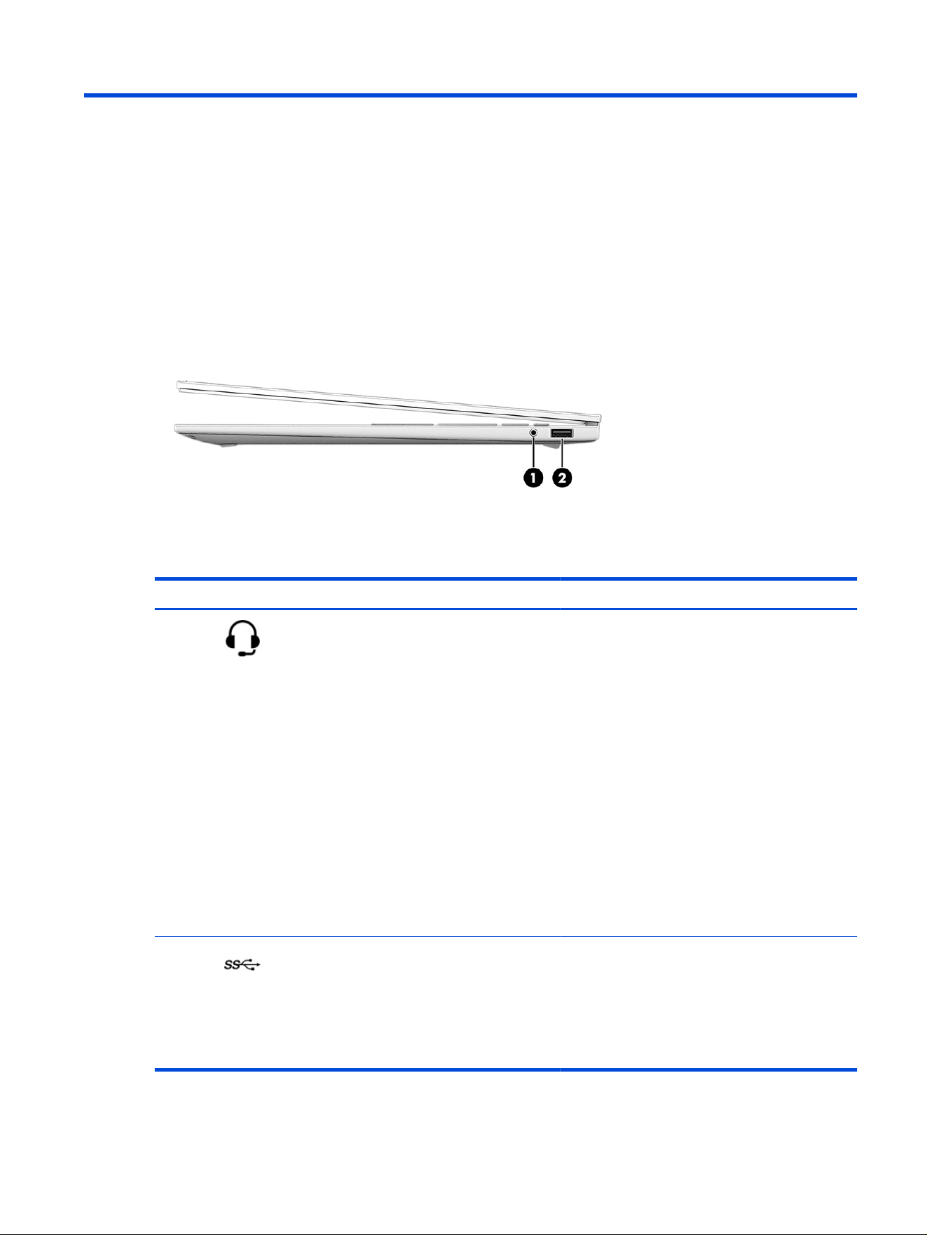
Right side
Use this illustration and table to identify the components on the right side of the computer.
Table 2-1 Right-side components and their descriptions
Component Description
(1) Audio-out (headphone)/Audio-in
(microphone) combo jack
Connects optional powered stereo speakers,
headphones, earbuds, a headset, or a television
audio cable. Also connects an optional headset
microphone. This jack does not support optional
standalone microphones.
WARNING! To reduce the risk of personal injury,
adjust the volume before putting on headphones,
earbuds, or a headset. For additional safety
information, see the
Regulatory, Safety, and
Environmental Notices.
To access this guide:
■
Select the Search icon in the taskbar, type HP
Documentation in the search box, and then
select HP Documentation.
NOTE: When a device is connected to the jack, the
computer speakers are disabled.
(2)
USB port Connects a USB device, provides data transfer, and
(for select products) charges small devices (such as
a smartphone) when the computer is on or in sleep
mode.
NOTE: Use a standard USB Type-A charging cable
or cable adapter (purchased separately) when
charging a small external device.
Getting to know your computer 5
Left side
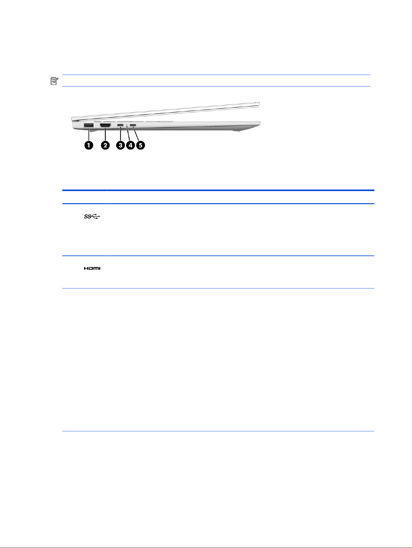
Use this illustration and table to identify the components on the left side of the computer.
NOTE: Images shown may vary from your actual product image.
Table 2-2 Left-side components and their descriptions
Component Description
(1) USB port Connects a USB device, provides data transfer, and (for select
products) charges small devices (such as a smartphone)
when the computer is on or in sleep mode.
NOTE: Use a standard USB Type-A charging cable or cable
adapter (purchased separately) when charging a small
external device.
(2) HDMI port Connects an optional video or audio device, such as a
high-denition television, any compatible digital or audio
component, or a high-speed High-Denition Multimedia
Interface (HDMI) device.
(3) USB Type-C power connector and
Thunderbolt port (select models only) with HP
Sleep and Charge and DisplayPort output
Connects an AC adapter that has a USB Type-C connector,
supplying power to the computer and, if needed, charging the
computer battery.
– and –
Connects a USB device, provides high-speed data transfer,
and charges small devices (such as a smartphone), even
when the computer is off.
NOTE: Use a standard USB Type-C charging cable or cable
adapter (purchased separately) when charging a small
external device.
– and –
Connects a display device that has a USB Type-C connector,
providing DisplayPort output.
NOTE: Your computer might also support a Thunderbolt
docking station.
6
Chapter 2 Getting to know your computer

Table 2-2 Left-side components and their descriptions (continued)
Component Description
(4) AC adapter and battery light ● White: The AC adapter is connected and the battery is
fully charged.
● Blinking amber: The AC adapter is disconnected and the
battery has reached a low battery level.
● Amber: The AC adapter is connected and the battery is
charging.
● Off: The battery is not charging.
(5) USB Type-C power connector and
Thunderbolt port (select models only) with
HP Sleep and Charge and DisplayPort output
(select models only)
Connects an AC adapter that has a USB Type-C connector,
supplying power to the computer and, if needed, charging the
computer battery.
– and –
Connects a USB device, provides high-speed data transfer,
and charges small devices (such as a smartphone), even
when the computer is off.
NOTE: Use a standard USB Type-C charging cable or cable
adapter (purchased separately) when charging a small
external device.
– and –
Connects a display device that has a USB Type-C connector,
providing DisplayPort output.
NOTE: Your computer might also support a Thunderbolt
docking station.
Display
The computer display can include essential components such as speakers, antennas, cameras, and
microphones.
Low blue light mode (select products only)
Your computer display is shipped from the factory in low blue light mode for improved eye comfort and
safety. Also, blue light mode automatically adjusts blue light emissions when you are using the computer at
night or for reading.
WARNING! To reduce the risk of serious injury, read the Safety & Comfort Guide. It describes proper
workstation setup and proper posture, health, and work habits for computer users. The Safety & Comfort
Guide also provides important electrical and mechanical safety information. The Safety & Comfort
Guide is available on the web at http://www.hp.com/ergo.
Wake-on-voice (select products only)
Use the wake-on-voice feature to wake or interact with your computer quickly.
To access the wake-on-voice settings, follow these steps:
1. Select the Search icon in the taskbar, type Xiaowei in the search box, and then select Xiaowei.
Display
7
2. When the tool opens, scan the QR code with your mobile device, which takes you to the settings page,
where you can select your wake-on-voice features.
3. Follow the on-screen instructions.
NOTE: Allow the Xiaowei app to continue running on the computer.
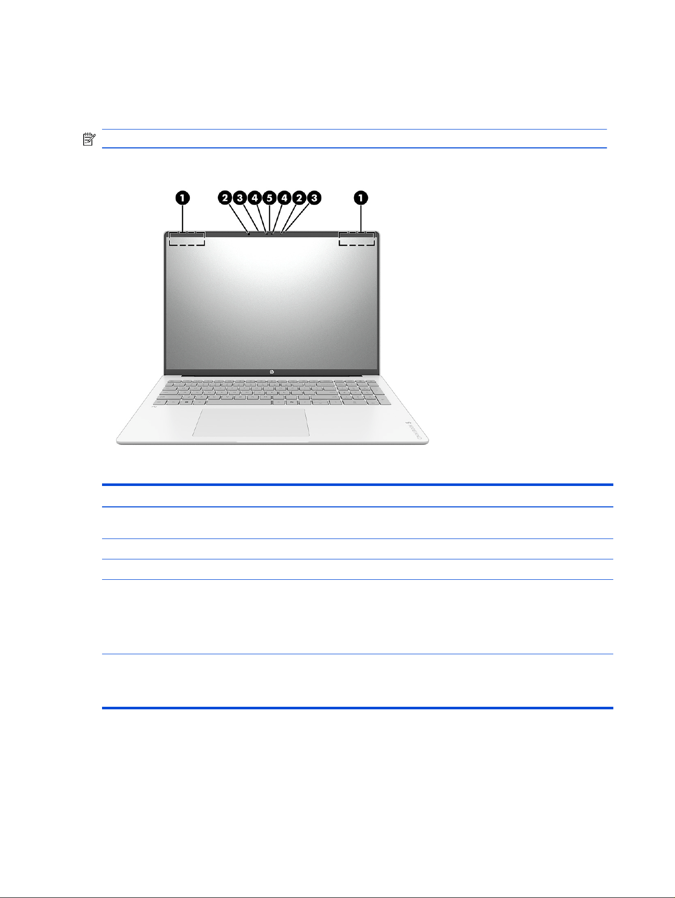
Use this illustration and table to identify components on the display.
Table 2-3 Display components and their descriptions
Component Description
(1) WLAN antennas* Send and receive wireless signals to communicate with wireless
local area networks (WLANs).
(2) Camera lights (2) On: One or more cameras are in use.
(3) Internal microphones (2) Record sound.
(4) Cameras (2) Allow you to video chat, record video, and record still images. Some
cameras also allow a facial recognition logon to Windows, instead
of a password logon.
NOTE: Camera functions vary depending on the camera
hardware and software installed on your product.
(5) Camera privacy cover By default, the camera lens is uncovered, but you can slide the
camera privacy cover to block the cameraʼs view. To use the
camera, slide the camera privacy cover in the opposite direction
to reveal the lens.
*The antennas are not visible from the outside of the computer. For optimal transmission, keep the areas
immediately around the antennas free from obstructions.
For wireless regulatory notices, see the section of the Regulatory, Safety, and Environmental Notices that
applies to your country or region.
8
Chapter 2 Getting to know your computer

To access this guide:
■
Select the Search icon in the taskbar, type HP Documentation in the search box, and then select
HP Documentation.
Keyboard area
Keyboards can vary by language.
NOTE: The keyboard area, including the function keys and (select products only) power key, is disabled
in stand, tent, and tablet modes. To enable the keyboard, including the power key, change to the clamshell
mode.
Touchpad settings and components
Learn the touchpad settings and components.
Touchpad settings
Learn how to adjust touchpad settings.
Adjusting touchpad settings
Use these steps to adjust touchpad settings and gestures.
1. Select the Search icon in the taskbar, type touchpad settings in the search box, and then press
enter.
2. Choose a setting.
Turning on the touchpad
Follow these steps to turn on the touchpad.
1. Select the Search icon in the taskbar, type touchpad settings in the search box, and then press
enter.
2. Using an external mouse, click the touchpad button.
If you are not using an external mouse, press the Tab key repeatedly until the pointer rests on the
touchpad button. Then press the spacebar to select the button.
Touchpad components
Use this illustration and table to identify the touchpad components.
Keyboard area
9
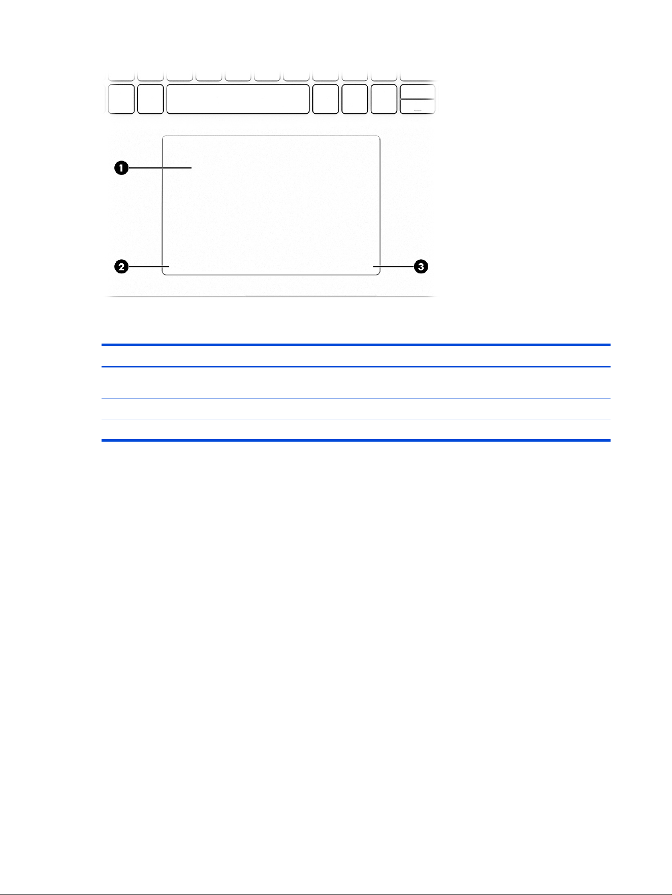
Table 2-4 Touchpad components and their descriptions
Component Description
(1) Touchpad zone Reads your nger gestures to move the pointer or activate items on
the screen.
(2) Left touchpad button Functions like the left button on an external mouse.
(3) Right touchpad button Functions like the right button on an external mouse.
Lights
Use this illustration and table to identify the lights on the computer.
10
Chapter 2 Getting to know your computer
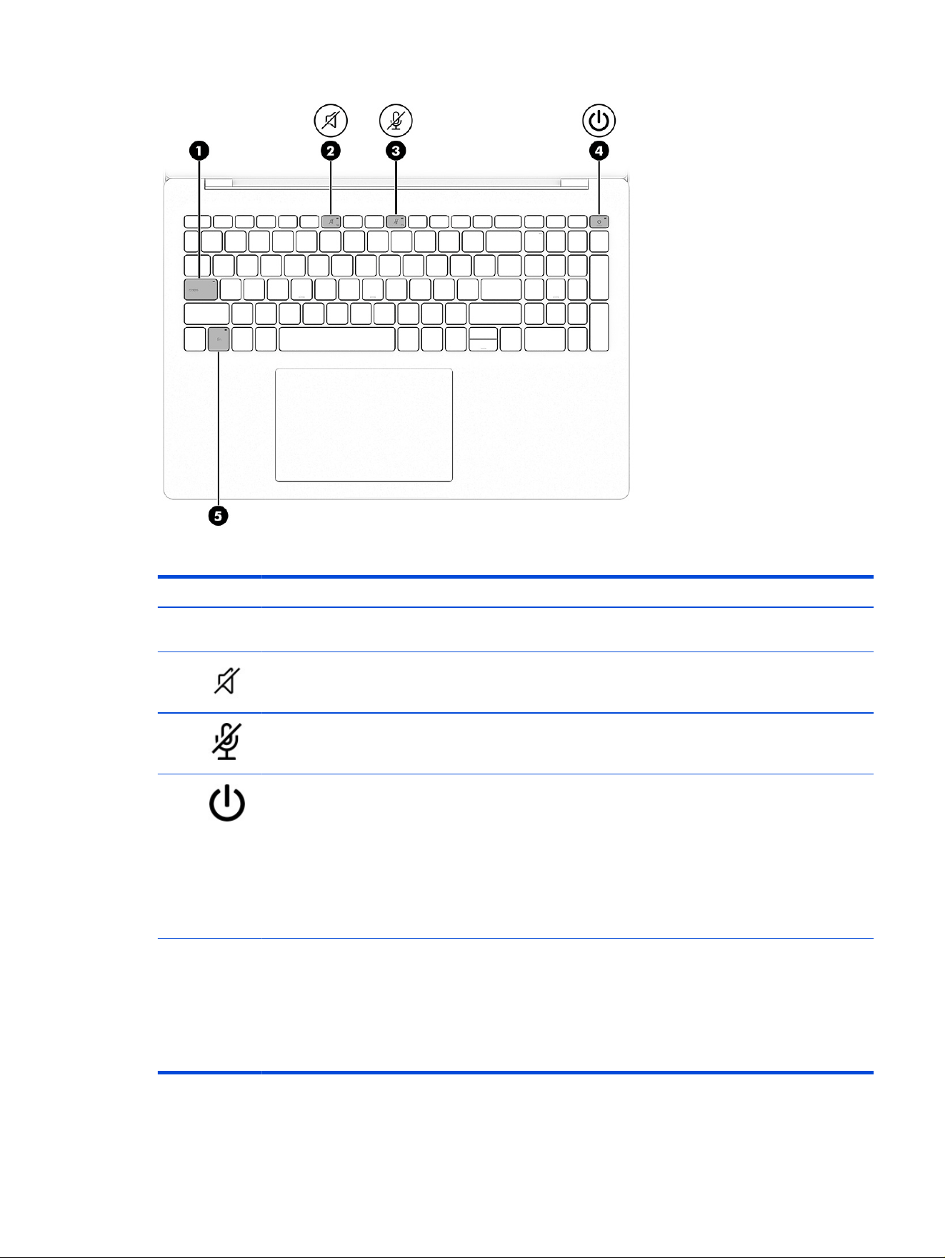
Table 2-5 Lights and their descriptions
Component Description
(1) Caps lock light On: Caps lock is on, which switches the key input to all capital
letters.
(2) Mute light ● On: Computer sound is off.
● Off: Computer sound is on.
(3) Microphone mute light ● On: Microphone is off.
● Off: Microphone is on.
(4) Power light ● On: The computer is on.
● Blinking (select products only): The computer is in
the sleep state, a power-saving state. The computer
shuts off power to the display and other unnecessary
components.
● Off: Depending on your computer model, the computer
is off, in hibernation, or in sleep. Hibernation is the power-
saving state that uses the least amount of power.
(5) Fn lock light ● On: FN Lock is enabled.
● Off: FN Lock is disabled.
NOTE: On some products, FN Lock is assigned as the
secondary function of the left Shift key. To enable FN Lock,
press fn + left Shift. Repeat the same key combination again
to disable FN Lock.
Lights 11

Special keys
Use this illustration to identify the special keys.
Table 2-6 Special keys and their descriptions
Component Description
(1) Power button ● When the computer is off, press the button briey to turn
on the computer.
● When the computer is on, press the button briey to
initiate sleep.
● When the computer is in the sleep state, press the button
briey to exit sleep (select products only).
● When the computer is in hibernation, press the button
briey to exit hibernation.
IMPORTANT: Pressing and holding down the power button
results in the loss of unsaved information.
If the computer has stopped responding and shutdown
procedures are ineffective, press and hold the power button
down for at least 10 seconds to turn off the computer.
To learn more about your power and sleep settings:
■
Right-click the Power icon , and then select Power
and sleep settings.
(2)
esc key Displays system information when pressed in combination
with the fn key.
(3) fn key Executes specic functions when pressed in combination with
another key.
NOTE: When using combination shortcut keys, the order in
which keys are pressed may affect the result.
12 Chapter 2 Getting to know your computer
Table 2-6 Special keys and their descriptions (continued)
Component Description
(4) Windows key Opens the Start menu.
NOTE: Pressing the Windows key again will close the Start
menu.
(5) Action keys Execute frequently used system functions as dened by the
icon symbols on f1 through f12 function keys.
(6) Windows Copilot key Opens Windows Copilot (select products only).
NOTE: Copilot in Windows (select products only) requires
Windows 11. Some features require a neural processing unit
(NPU). The timing of feature delivery and availability varies by
market and device. You must have a Microsoft account to use
the Copilot feature. When the Copilot feature is not available,
pressing the Copilot key opens the Bing search engine. See
http://aka.ms/WindowsAIFeatures.
(7) num lock key Alternates between the navigational and numeric functions on
the integrated numeric keypad.
(8) Integrated numeric keypad A separate keypad to the right of the alphabet keyboard. When
num lock is pressed, the keypad can be used like an external
numeric keypad.
NOTE: If the keypad function is active when the computer is
turned off, that function is reinstated when the computer is
turned back on.
Bottom
Identify the bottom components.
Table 2-7
Bottom components and their descriptions
Component Description
(1) Speakers (2) Produce sound.
Bottom 13
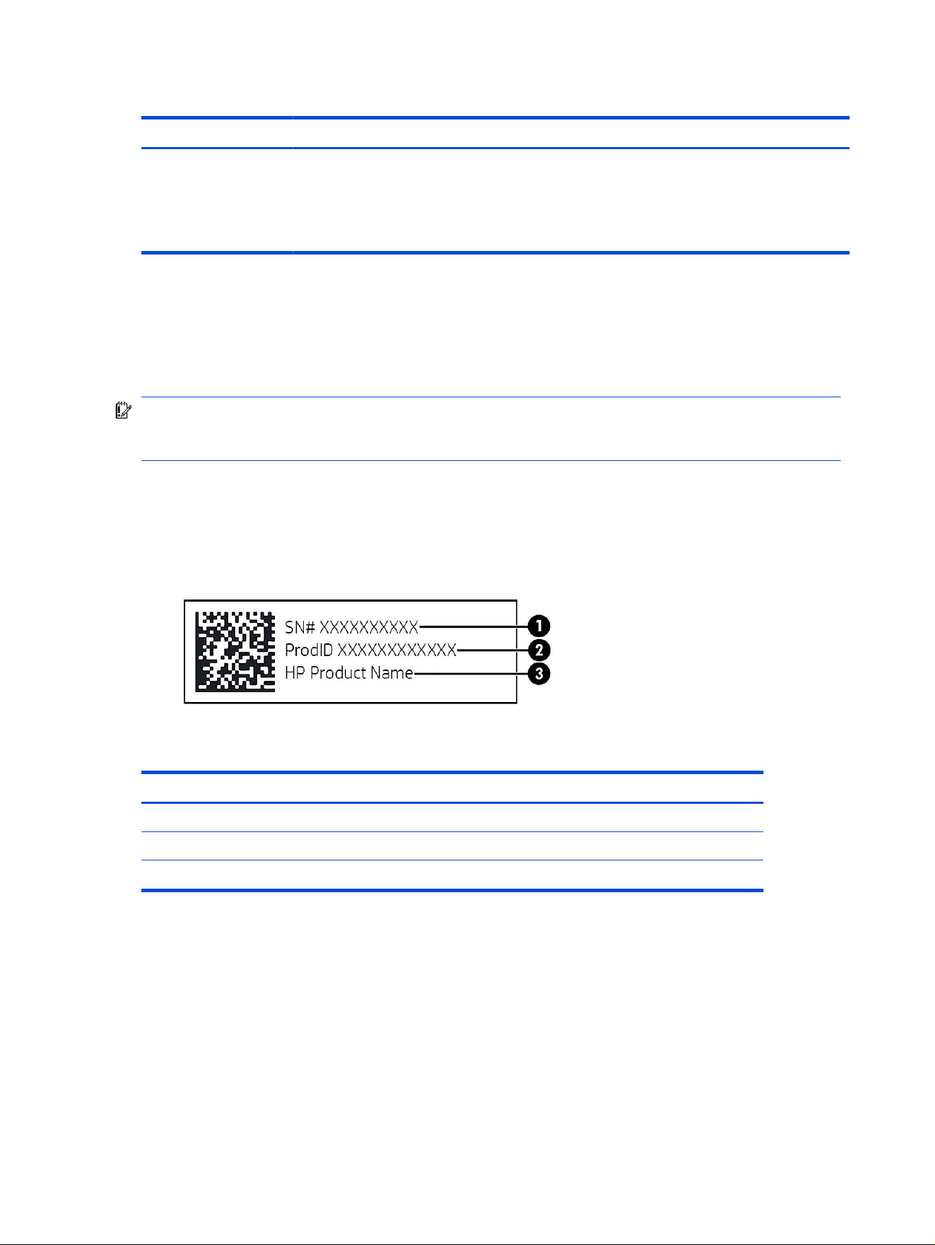
Table 2-7 Bottom components and their descriptions (continued)
Component Description
(2) Vent Enables airow to cool internal components.
NOTE: The computer fan starts up automatically to
cool internal components and prevent overheating. It is
normal for the internal fan to cycle on and off during
routine operation.
Labels
The labels afxed to the computer provide information that you might need when you troubleshoot system
problems or travel internationally with the computer. Labels can be in paper form or imprinted on the
product.
IMPORTANT: Check the following locations for the labels described in this section: the bottom of the
computer, inside the battery bay, under the service door, on the back of the display, or on the bottom of a
tablet kickstand.
● Service label—Provides important information to identify your computer. When contacting support,
you might be asked for the serial number, the product number, or the model number. Locate this
information before you contact support.
Your service label will resemble the following example:
Table 2-8
Service label components
Component
(1) Serial number
(2) Product ID
(3) HP product name and model number
● Regulatory labels—Provide regulatory information about the computer.
● Wireless certication labels—Provide information about optional wireless devices and the approval
markings for the countries or regions in which the devices have been approved for use.
14
Chapter 2 Getting to know your computer

Illustrated parts catalog3
Use this chapter to determine the spare parts that are available for the computer.
Computer major components
Use this illustration and table to identify the computer major components.
NOTE: HP continually improves and changes product parts. For complete and current information
about supported parts for your computer, go to http://partsurfer.hp.com, select your country or region,
and then follow the on-screen instructions.
NOTE: Details about your computer, including model, serial number, product key, and length of
warranty, are on the service tag at the bottom of your computer.
Illustrated parts catalog
15
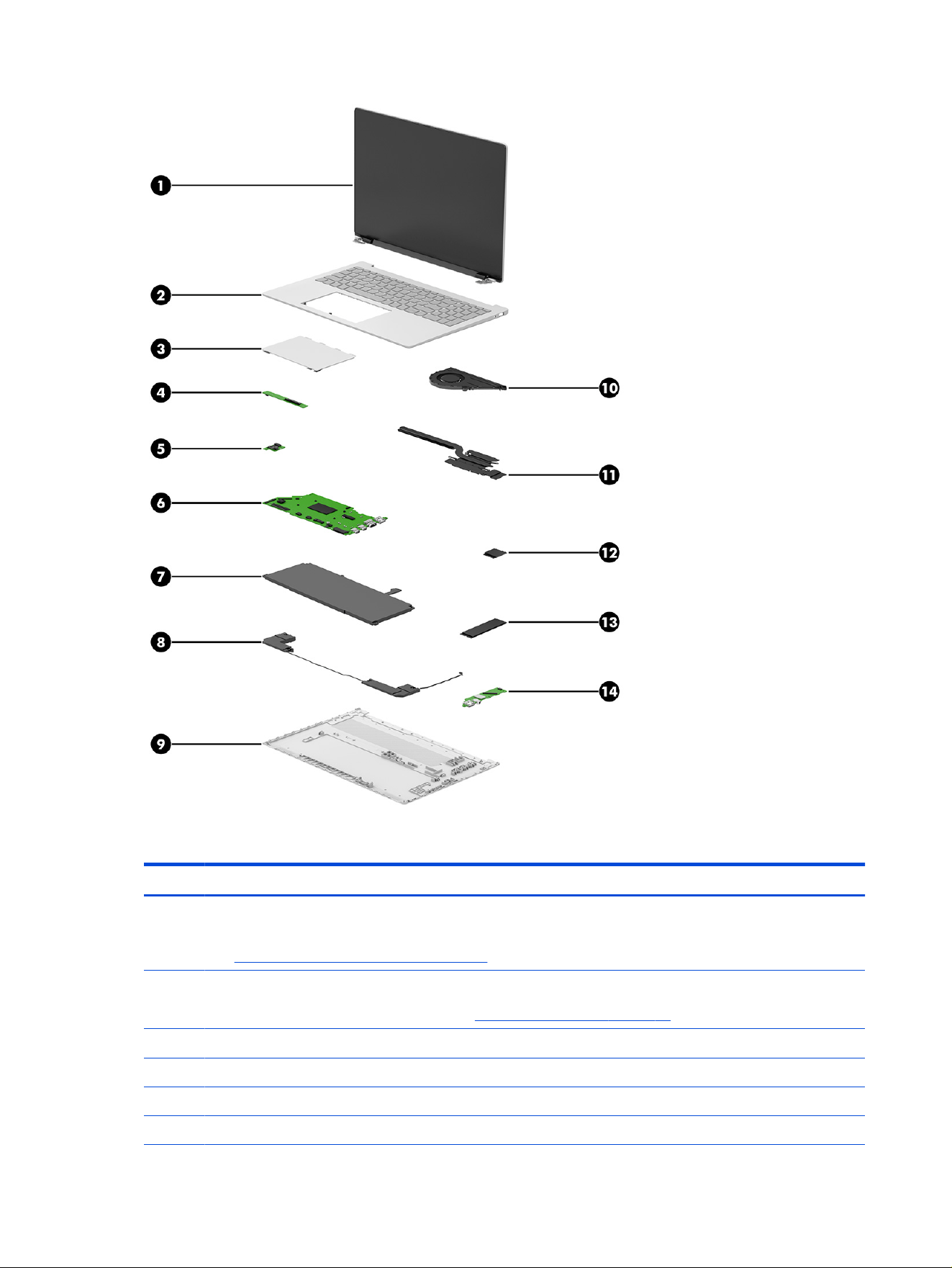
Table 3-1 Computer major component descriptions and part numbers
Item Component Spare part number
(1) Display assembly
NOTE: Display spare parts are available only as subcomponents. For spare part information,
see Display assembly subcomponents on page 19.
(2) Top cover with keyboard
NOTE: For a detailed list of country codes, see Keyboard with top cover on page 62.
Glacier silver P83599-001
Meteor silver P83600-001
Silk sand P83601-001
Starlit blue P83602-001
16 Chapter 3 Illustrated parts catalog

Table 3-1 Computer major component descriptions and part numbers (continued)
Item Component Spare part number
(3) Touchpad
Glacier silver P83628-001
Meteor silver P83629-001
Silk sand P83630-001
Starlit blue P83631-001
(4) Transition board (with cable) P83617-001
(5) Power management board P83616-001
(6) System board for use in models with an AMD processor (includes integrated processor, the
Windows operating system, and either 32 or 16 Gb of integrated memory)
AMD Ryzen AI 9 465 (32 GB) P83638-601
AMD Ryzen AI 9 465 (32 GB, the Peopleʼs Republic of China [PRC]) P83643-601
AMD Ryzen AI 7 445 (32 GB) P83637-601
AMD Ryzen AI 7 445 (32 GB, PRC) P83642-601
AMD Ryzen AI 7 445 (24 GB) Q12513-601
AMD Ryzen AI 7H 445 (24 GB, PRC) Q12514-601
AMD Ryzen AI 7 445 (16 GB) P83636-601
AMD Ryzen AI 7 445 (16 GB, PRC) P83641-601
AMD Ryzen AI 5 430 (16 GB) P83639-601
AMD Ryzen AI 5 430 (16 GB, PRC) P83640-601
AMD Ryzen AI 5 330 (32 GB) Q06472-601
AMD Ryzen AI 5 330 (32 GB, PRC) Q06473-601
AMD Ryzen AI 5 330 (24 GB) Q12511-601
AMD Ryzen AI 5 330 (24 GB, PRC) Q12512-601
AMD Ryzen AI 5 330 (16 GB) Q06470-601
AMD Ryzen AI 5 330 (16 GB, PRC) Q06471-601
AMD Ryzen 7 250 (32 GB) P83646-601
AMD Ryzen 7 250 (32 GB, PRC) P83647-601
AMD Ryzen 7 250 (16 GB) P83644-601
AMD Ryzen 7 250 (16 GB, PRC) P83645-601
AMD Ryzen 5 230 (16 GB) P83648-601
AMD Ryzen 5 230 (16 GB, PRC) P83649-601
System board for use in models with an Intel processor
Intel Core Ultra 9 386H processor, 32 GB P83593-601
Intel Core Ultra 7 355 processor, 32 GB P83592-601
Intel Core Ultra 7 355 processor, 16 GB P83591-601
Computer major components 17

Table 3-1 Computer major component descriptions and part numbers (continued)
Item Component Spare part number
Intel Core 7 150U processor, 16 GB P83594-601
Intel Core Ultra 5 322 processor, 24 GB Q12510-601
Intel Core Ultra 5 322 processor, 16 GB P83590-601
Intel Core Ultra 5 120U processor, 16 GB P83589-601
Intel Core i7 350 processor, 24 GB Q15982-601
Intel Core i7 350 processor, 16 GB Q08416-601
Intel Core i5 320 processor, 32 GB Q08415-601
Intel Core i5 320 processor, 24 GB Q15981-601
Intel Core i5 320 processor, 16 GB Q08414-601
(7) Battery (4-cell, 68 Whr, 4.405 Ah capacity, polymer lithium [PL]) P13980-001
(8) Speakers P83621-001
(9) Bottom cover
Glacier silver P83603-001
Meteor silver P83604-001
Silk sand P83605-001
Starlit blue P83606-001
(10) Fan P83622-001
(11) Heat sink assembly
AMD:
For use in models with an AMD Ryzen AI 9 465 processor P83625-001
For use in models with an AMD Ryzen AI 7 445 processor P83627-001
For use in models with an AMD Ryzen AI 5 430 or AMD Ryzen 7 250 processor P83626-001
Intel:
For use in models with Intel Core Ultra 5, 7, and 9 processors P83624-001
For use in models with Intel Core 5 and 7 processors P83623-001
(12) WLAN module
Intel BE211 with Bluetooth 6.0, M.2 2230, non-vPro P36621-005
Intel AX8922AE with Bluetooth 5.4, M.2 2230 P44408-005
MediaTek MT7920 with Bluetooth 5.4, Wi-Fi 6, M.2 2230 P17386-005
Realtek RTL8852BE with Bluetooth 5.4, M.2 2230 P06350-005
(13) SSD (M.2 2280)
1 Tb PCIe 5×4 Non-Volatile Memory Express (NVMe) P73030-005
1 Tb PCIe NVMe N77394-005
512 GB PCIe 5×4 NVMe P73029-005
18 Chapter 3 Illustrated parts catalog
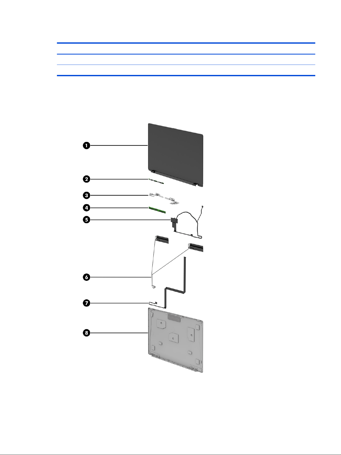
Table 3-1 Computer major component descriptions and part numbers (continued)
Item Component Spare part number
512 GB PCIe NVMe N77392-005
(14) USB board P83615-001
Display assembly subcomponents
Use this illustration and table to identify the display assembly subcomponents.
Display assembly subcomponents 19

Table 3-2 Display component descriptions and part numbers
Item Component Spare part number
(1) Display panel
NOTE: Display panel adhesive is available as spare part number N36079-001.
2.8K (2880 × 1800), antiglare, OLED, at (3.2 mm), 45% NTSC, embedded DisplayPort (eDP) 1.5,
500 nits, 120 Hz (variable rate refresh [VRR])
P83597-001
Full high-denition (FHD) (1920 × 1200), touchscreen, antiglare, OLED, at (3.2 mm), 45% NTSC,
embedded DisplayPort (eDP) 1.2, 300 nits, 60 Hz (variable rate refresh [VRR])
P83598-001
Full high-denition (FHD) (1920 × 1200), non-touchscreen, antiglare, OLED, at (3.2 mm), 45%
NTSC, embedded DisplayPort (eDP) 1.2, 300 nits, 60 Hz (variable rate refresh [VRR])
P83596-001
(2) Camera module (includes rubber spacer) P83632-001
(3) Display hinges (includes left and right hinges) P83633-001
(4) Touch control board (with cable)
For use in models with AMD processors P84442-001
For use in models with Intel processors P83635-001
(5) Display cable
For use in models with AMD processors P83929-001
For use in models with Intel processors P83618-001
(6) WLAN antenna cable (included in cable kit, with antenna cables and transceivers) P83619-001
(7) Touch control cable (included in cable kit) P83619-001
(8) Display back cover
Touchscreen
Glacier silver P83611-001
Meteor silver P83612-001
Silk sand P83613-001
Starlit blue P83614-001
Non-touchscreen
Glacier silver P83607-001
Meteor silver P83608-001
Silk sand P83609-001
Starlit blue P83610-001
Miscellaneous parts
Use this table to identify the miscellaneous parts.
20
Chapter 3 Illustrated parts catalog

Table 3-3 Miscellaneous part descriptions and part numbers
Component Spare part number
AC adapters
65 W USB Type-C, straight cable P38779-001
65W AC adapter with Gallium Nitride technology (GaN), wall-mountable (WM), USB-C® connector,
2-piece (2P), 2.0-meter cable, xed
P58629-001
65W AC adapter GaN, WM, USB-C, (2P), 2.0-meter cable, detachable P58630-001
65W AC adapter, USB-C connector, WM, 2P P68491-001
65W AC adapter GaN, WM, USB-C connector, 2P, inline P73759-001
Cable Kit (with antenna) P83619-001
Power cords (C5, 1.0 m)
Australia L19358-001
Denmark L19360-001
Europe L19361-001
India L19363-001
Israel L19362-001
Italy L19364-001
Japan L19365-001
North America L19367-001
South Africa L19369-001
South Korea L19366-001
Switzerland L19370-001
Taiwan L19372-001
Thailand L19371-001
Thailand (with ADP) M85418-001
United Kingdom L19373-001
Power cords (duckhead, 1.0 m)
Australia P57784-001
Europe P57782-001
India P57790-001
South Korea P57785-001
Thailand P57786-001
United Kingdom P57783-001
Screw Kit P83620-001
Miscellaneous parts 21

Removal and replacement procedures
preliminary requirements
4
Use this information to properly prepare to disassemble and reassemble the computer.
Tools required
You need the following tools to complete the removal and replacement procedures.
● Tweezers
● Nonconductive, nonmarking pry tool
● Magnetic Phillips P1 screwdriver
Service considerations
The following sections include some of the considerations that you must keep in mind during disassembly
and assembly procedures.
NOTE: As you remove each subassembly from the computer, place the subassembly and all
accompanying screws away from the work area to prevent damage.
Plastic parts
Using excessive force during disassembly and reassembly can damage plastic parts.
Cables and connectors
Handle cables with extreme care to avoid damage.
IMPORTANT: When servicing the computer, be sure that cables are placed in their proper locations
during the reassembly process. Improper cable placement can damage the computer.
Apply only the tension required to unseat or seat the cables during removal and insertion. Handle cables
by the connector whenever possible. In all cases, avoid bending, twisting, or tearing cables. Be sure that
cables are routed so that they cannot be caught or snagged as you remove or replace parts. Handle ex
cables with extreme care; these cables tear easily.
Drive handling
Note the following guidelines when handling drives.
IMPORTANT: Drives are fragile components. Handle them with care. To prevent damage to the
computer, damage to a drive, or loss of information, observe these precautions:
● Before removing or inserting a hard drive, shut down the computer. If you are unsure whether the
computer is off or in hibernation or sleep mode, turn the computer on, and then shut it down through
the operating system.
22
Chapter 4 Removal and replacement procedures preliminary requirements

● Before handling a drive, be sure that you are discharged of static electricity. While handling a drive,
avoid touching the connector.
● Before removing an optical drive, be sure that a disc is not in the drive, and be sure that the optical
drive tray is closed.
● Handle drives on surfaces covered with at least 2.54 cm (1 inch) of shock-proof foam.
● Avoid dropping drives from any height onto any surface.
● After removing a hard drive or an optical drive, place it in a static-proof bag.
● Avoid exposing an internal hard drive to products that have magnetic elds, such as monitors or
speakers.
● Avoid exposing a drive to temperature extremes or liquids.
● If a drive must be mailed, place the drive in a bubble pack mailer or other suitable form of protective
packaging, and label the package “FRAGILE.”
Electrostatic discharge information
A sudden discharge of static electricity from your nger or other conductor can destroy static-sensitive
devices or microcircuitry. Often the spark is neither felt nor heard, but damage occurs. An electronic
device exposed to electrostatic discharge (ESD) might not appear to be affected at all and can work
perfectly throughout a normal cycle. The device might function normally for a while, but it has been
degraded in the internal layers, reducing its life expectancy.
Networks built into many integrated circuits provide some protection, but in many cases, the discharge
contains enough power to alter device parameters or melt silicon junctions.
IMPORTANT: To prevent damage to the device when you remove or install internal components,
observe these precautions:
● Keep components in their electrostatic-safe containers until you are ready to install them.
● Before touching an electronic component, discharge static electricity by using the guidelines
described in Personal grounding methods and equipment on page 24.
● Avoid touching pins, leads, and circuitry. Handle electronic components as little as possible.
● If you remove a component, place it in an electrostatic-safe container.
Generating static electricity
Follow these static electricity guidelines.
● Different activities generate different amounts of static electricity.
● Static electricity increases as humidity decreases.
Electrostatic discharge information
23

Table 4-1 Static electricity occurrence based on activity and humidity
Event 55% relative
humidity
40% relative
humidity
10% relative
humidity
Walking across carpet
Walking across vinyl oor
Motions of bench worker
Removing dual in-line packages (DIPs) from plastic tube
7500 V
3000 V
400 V
400 V
15,000 V
5000 V
800 V
700 V
35,000 V
12,000 V
6000 V
2000 V
Removing DIPs from vinyl tray
Removing DIPs from polystyrene foam
Removing bubble pack from PCB (printed circuit board)
Packing PCBs in foam-lined box
2000 V
3500 V
7000 V
5000 V
4000 V
5000 V
20,000 V
11,000 V
11,500 V
14,500 V
26,500 V
21,000 V
NOTE:
Multiple electric components can be packaged together in plastic tubes, trays, or polystyrene
foam.
NOTE: As little as 700 V of static electricity can degrade a product.
Preventing electrostatic damage to equipment
Many electronic components are sensitive to ESD. Circuitry design and structure determine the degree of
sensitivity.
The following packaging and grounding precautions are necessary to prevent static electricity damage to
electronic components:
● To avoid hand contact, transport products in static-safe containers such as tubes, bags, or boxes.
● Protect all electrostatic parts and assemblies with conductive or approved containers or packaging.
● Keep electrostatic-sensitive parts in their containers until they arrive at static-free stations.
● Place items on a grounded surface before removing them from their container.
● Always be properly grounded when touching a sensitive component or assembly.
● Avoid contact with pins, leads, or circuitry.
● Place reusable electrostatic-sensitive parts from assemblies in protective packaging or conductive
foam.
Personal grounding methods and equipment
Using certain equipment can prevent static electricity damage to electronic components.
● Wrist straps are exible straps with a maximum of 1 MΩ ±10% resistance in the ground cords. To
provide proper ground, wear a strap snug against bare skin. Verify that the ground cord is connected
and ts snugly into the banana plug connector on the grounding mat or workstation.
● You can use heel straps, toe straps, and boot straps at standing workstations. These straps are
compatible with most types of shoes or boots. On conductive oors or dissipative oor mats, use
them on both feet with a maximum of 1 MΩ ±10% resistance between the operator and ground.
24
Chapter 4 Removal and replacement procedures preliminary requirements

Table 4-2 Static shielding protection levels
Method Voltage
Antistatic plastic
Carbon-loaded plastic
Metalized laminate
1500
7500
15,000
Grounding the work area
To prevent static damage at the work area, follow these precautions.
● Cover the work surface with approved static-dissipative material.
● Use a wrist strap connected to a properly grounded work surface and use properly grounded tools
and equipment.
● Use static-dissipative mats, foot straps, or air ionizers to give added protection.
● Handle electrostatic sensitive components, parts, and assemblies by the case or PCB laminate.
Handle them only at static-free work areas.
● Turn off power and input signals before inserting and removing connectors or test equipment.
● Use xtures made of static-safe materials when xtures must directly contact dissipative surfaces.
● Keep the work area free of nonconductive materials, such as ordinary plastic assembly aids and
polystyrene foam.
● Use conductive eld service tools, such as cutters, screwdrivers, and vacuums.
● Avoid contact with pins, leads, or circuitry.
Recommended materials and equipment
HP recommends certain materials and equipment to prevent static electricity.
● Antistatic tape
● Antistatic smocks, aprons, or sleeve protectors
● Conductive bins and other assembly or soldering aids
● Conductive foam
● Conductive tabletop workstations with ground cord of 1 MΩ ±10% resistance
● Static-dissipative table or oor mats with hard tie to ground
● Field service kits
● Static awareness labels
● Wrist straps and footwear straps providing 1 MΩ ±10% resistance
● Material handling packages
● Conductive plastic bags
Grounding the work area
25

● Conductive plastic tubes
● Conductive tote boxes
● Opaque shielding bags
● Transparent metallized shielding bags
● Transparent shielding tubes
Cleaning your computer
Cleaning your computer regularly removes dirt and debris so that your device continues to operate at its
best. Use the following information to safely clean the external surfaces of your computer.
Enabling HP Easy Clean (select products only)
HP Easy Clean helps you to avoid accidental input while you clean the computer surfaces. This software
disables devices such as the keyboard, touch screen, and touchpad for a preset amount of time so that
you can clean all computer surfaces.
1. Start HP Easy Clean in one of the following ways:
● Select the Start menu, and then select HP Easy Clean.
● Select the HP Easy Clean icon in the taskbar.
● Select Start, and then select the HP Easy Clean tile.
2. Now that your device is disabled for a short period, see Removing dirt and debris from your
computer on page 26 for the recommended steps to clean the high-touch, external surfaces
on your computer. After you remove the dirt and debris, you can also clean the surfaces with a
disinfectant. See Cleaning your computer with a disinfectant on page 27 for guidelines to help
prevent the spread of harmful bacteria and viruses.
Removing dirt and debris from your computer
Here are the recommended steps to clean dirt and debris from your computer.
For computers with wood veneer, see Caring for wood veneer (select products only) on page 28.
1. Wear disposable gloves made of latex (or nitrile gloves, if you are latex-sensitive) when cleaning the
surfaces.
2. Turn off your device and unplug the power cord and other connected external devices. Remove any
installed batteries from items such as wireless keyboards.
CAUTION: To prevent electric shock or damage to components, never clean a product while it is
turned on or plugged in.
3. Moisten a microber cloth with water. The cloth should be moist, but not dripping wet.
IMPORTANT: To avoid damaging the surface, avoid abrasive cloths, towels, and paper towels.
26
Chapter 4 Removal and replacement procedures preliminary requirements

4. Wipe the exterior of the product gently with the moistened cloth.
IMPORTANT: Keep liquids away from the product. Avoid getting moisture in any openings. If liquid
makes its way inside your HP product, it can cause damage to the product. Do not spray liquids
directly on the product. Do not use aerosol sprays, solvents, abrasives, or cleaners containing
hydrogen peroxide or bleach that might damage the nish.
5. Start with the display (if applicable). Wipe carefully in one direction, and move from the top of the
display to the bottom. Finish with any exible cables, like power cord, keyboard cable, and USB cables.
6. Be sure that surfaces have completely air-dried before turning the device on after cleaning.
7. Discard the gloves after each cleaning. Clean your hands immediately after you remove the gloves.
See Cleaning your computer with a disinfectant on page 27 for recommended steps to clean the high-
touch, external surfaces on your computer to help prevent the spread of harmful bacteria and viruses.
Cleaning your computer with a disinfectant
The World Health Organization (WHO) recommends cleaning surfaces, followed by disinfection, as a best
practice for preventing the spread of viral respiratory illnesses and harmful bacteria.
After cleaning the external surfaces of your computer using the steps in Removing dirt and debris from
your computer on page 26, Caring for wood veneer (select products only) on page 28, or both, you might
also choose to clean the surfaces with a disinfectant. A disinfectant that is within HP’s cleaning guidelines
is an alcohol solution consisting of 70% isopropyl alcohol and 30% water. This solution is also known as
rubbing alcohol and is sold in most stores.
Follow these steps when disinfecting high-touch, external surfaces on your computer:
1. Wear disposable gloves made of latex (or nitrile gloves, if you are latex-sensitive) when cleaning the
surfaces.
2. Turn off your device and unplug the power cord and other connected external devices. Remove any
installed batteries from items such as wireless keyboards.
CAUTION: To prevent electric shock or damage to components, never clean a product while it is
turned on or plugged in.
3. Moisten a microber cloth with a mixture of 70% isopropyl alcohol and 30% water. The cloth should
be moist, but not dripping wet.
CAUTION: Do not use any of the following chemicals or any solutions that contain them, including
spray-based surface cleaners: bleach, peroxides (including hydrogen peroxide), acetone, ammonia,
ethyl alcohol, methylene chloride, or any petroleum-based materials, such as gasoline, paint thinner,
benzene, or toluene.
IMPORTANT: To avoid damaging the surface, avoid abrasive cloths, towels, and paper towels.
4. Wipe the exterior of the product gently with the moistened cloth.
IMPORTANT: Keep liquids away from the product. Avoid getting moisture in any openings. If liquid
makes its way inside your HP product, it can cause damage to the product. Do not spray liquids
directly on the product. Do not use aerosol sprays, solvents, abrasives, or cleaners containing
hydrogen peroxide or bleach that might damage the nish.
Cleaning your computer with a disinfectant
27

5. Start with the display (if applicable). Wipe carefully in one direction, and move from the top of the
display to the bottom. Finish with any exible cables, like power cord, keyboard cable, and USB cables.
6. Be sure that surfaces have completely air-dried before turning the device on after cleaning.
7. Discard the gloves after each cleaning. Clean your hands immediately after you remove the gloves.
Caring for wood veneer (select products only)
Your product might feature high-quality wood veneer. As with all natural wood products, proper care is
important for best results over the life of the product. Because of the nature of natural wood, you might
see unique variations in the grain pattern or subtle variations in color, which are normal.
● Clean the wood with a dry, static-free microber cloth or chamois.
● Avoid cleaning products containing substances such as ammonia, methylene chloride, acetone,
turpentine, or other petroleum-based solvents.
● Do not expose the wood to sun or moisture for long periods of time.
● If the wood becomes wet, dry it by dabbing with an absorbent, lint-free cloth.
● Avoid contact with any substance that might dye or discolor the wood.
● Avoid contact with sharp objects or rough surfaces that might scratch the wood.
See Removing dirt and debris from your computer on page 26 for the recommended steps to clean the
high-touch, external surfaces on your computer. After you remove the dirt and debris, you can also clean
the surfaces with a disinfectant. See Cleaning your computer with a disinfectant on page 27 for sanitizing
guidelines to help prevent the spread of harmful bacteria and viruses.
Packaging and transporting guidelines
Follow these grounding guidelines when packaging and transporting equipment.
● To avoid hand contact, transport products in static-safe tubes, bags, or boxes.
● Protect ESD-sensitive parts and assemblies with conductive or approved containers or packaging.
● Keep ESD-sensitive parts in their containers until the parts arrive at static-free workstations.
● Place items on a grounded surface before removing items from their containers.
● Always be properly grounded when touching a component or assembly.
● Store reusable ESD-sensitive parts from assemblies in protective packaging or nonconductive foam.
● Use transporters and conveyors made of antistatic belts and roller bushings. Be sure that
mechanized equipment used for moving materials is wired to ground and that proper materials are
selected to avoid static charging. When grounding is not possible, use an ionizer to dissipate electric
charges.
Accessing support information
Use this information to nd the HP support that you need.
28
Chapter 4 Removal and replacement procedures preliminary requirements
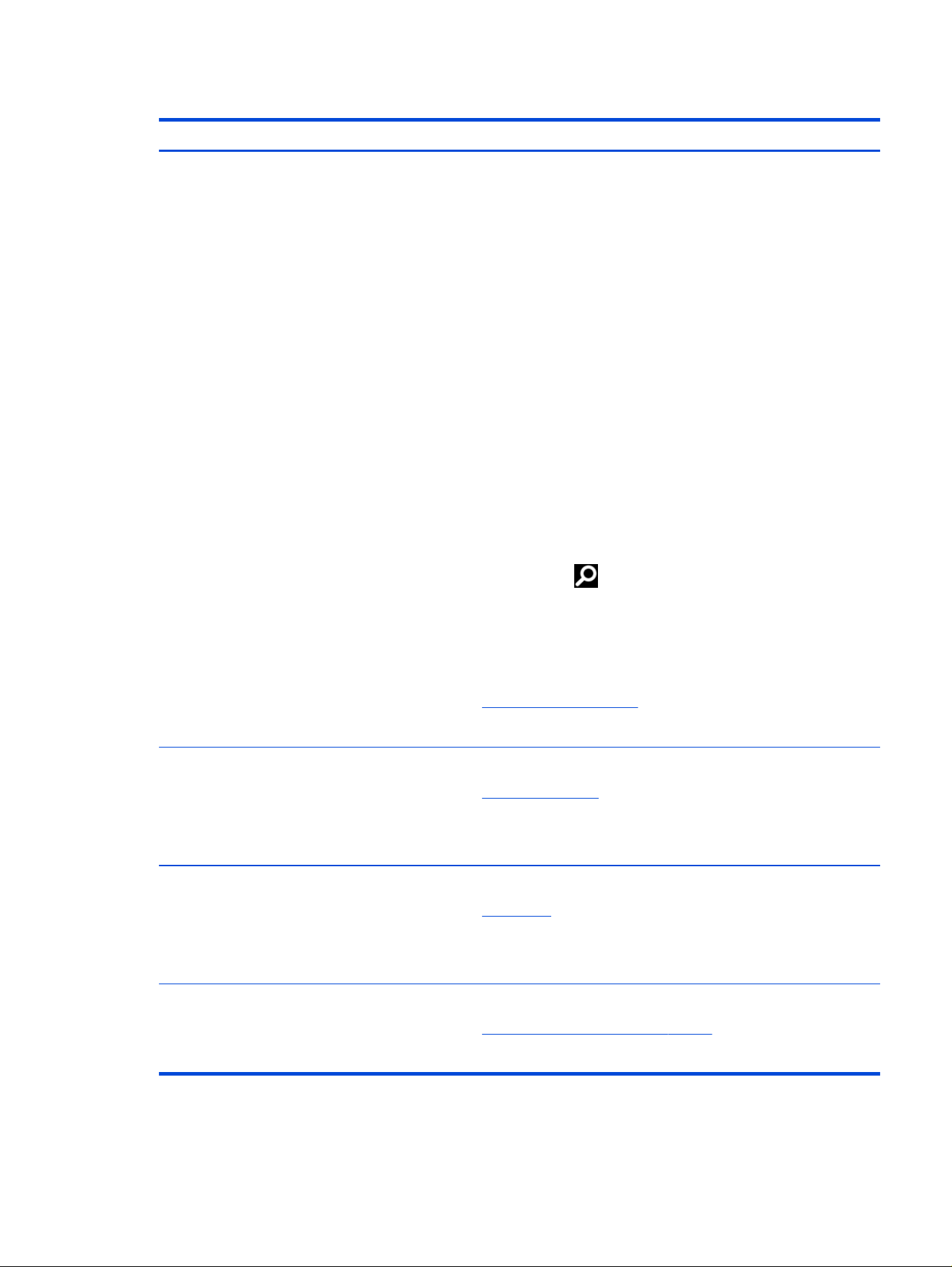
Table 4-3 Support information locations
Service consideration Path to access information
Records of reported failure incidents stored
on the computer
Windows®:
Pre-operating system failures are logged in the BIOS Event Log. To view the BIOS
Event Log:
1. Press the power button.
2. Immediately and repeatedly press esc when the power button light turns
white.
NOTE: If you do not press esc at the appropriate time, you must restart the
computer and again repeatedly press esc when the power button light turns
white to access the utility.
3. Press f10 to enter the BIOS setup.
4. Complete one of these tasks:
● (On commercial products) Under the Main tab, select BIOS event log,
and then select View BIOS Event Log.
● (On consumer products) Under the Main tab, select System Log.
Post-operating system failures are logged in the Event Viewer.
1. Turn on the computer and allow the operating system to open.
2. Select the search icon in the taskbar.
3. Type Event Viewer, and then press enter.
4. Select the log from the left panel. Details display in the right panel.
ChromeOS™:
1. Go to support.google.com/chrome.
2. Search collect Chrome device logs.
Technical bulletins and alerts
To nd technical bulletins, alerts, guides, and whitepapers:
1. Go to www.hp.com/support.
2. Follow the instructions to nd your product.
3. Select Bulletins and Alerts to view technical bulletins.
Repair professionals To locate repair professionals:
1. Go to www.hp.com.
2. Select Authorized service providers.
3. Select your location.
Component and diagnosis information,
failure detection, and required action
To locate diagnosis information and actions:
1. Go to http://www.hp.com/go/techcenter/pcdiags.
2. Select the issue you want to diagnose.
Accessing support information 29

Removal and replacement procedures
for Customer Self-Repair parts
5
This chapter provides removal and replacement procedures for Customer Self-Repair parts.
NOTE: The Customer Self-Repair program is not available in all locations. Installing a part that is not
supported by the Customer Self-Repair program can void your warranty. Check your warranty to
determine whether Customer Self-Repair is supported in your location.
NOTE: The HP Support YouTube Channel (in English) has videos that provide step-by-step removal and
replacement instructions for many common parts and models.
Component replacement procedures
Use these procedures to remove and replace computer components.
NOTE: Details about your computer, including model, serial number, product key, and length of
warranty, are on the service tag at the bottom of your computer.
NOTE: HP continually improves and changes product parts. For complete and current information
about supported parts for your computer, go to https://partsurfer.hp.com/, select your country or region,
and then follow the on-screen instructions.
Make special note of each screw size and location during removal and replacement.
Preparation for disassembly
Use these procedures to remove and replace computer components.
For initial safety procedures, see Removal and replacement procedures preliminary requirements on page
22.
1. Turn off the computer. If you are unsure whether the computer is off or in hibernation or sleep mode,
turn the computer on, and then shut it down through the operating system.
2. Disconnect power from the computer by unplugging the power cord from the computer.
3. Disconnect all external devices from the computer.
Bottom cover
Use these procedures and illustrations to remove the bottom cover.
Table 5-1
Bottom cover description and part number
Description Spare part number
Bottom cover (glacier silver) P83603-001
Bottom cover (meteor silver) P83604-001
Bottom cover (silk sand) P83605-001
30 Chapter 5 Removal and replacement procedures for Customer Self-Repair parts
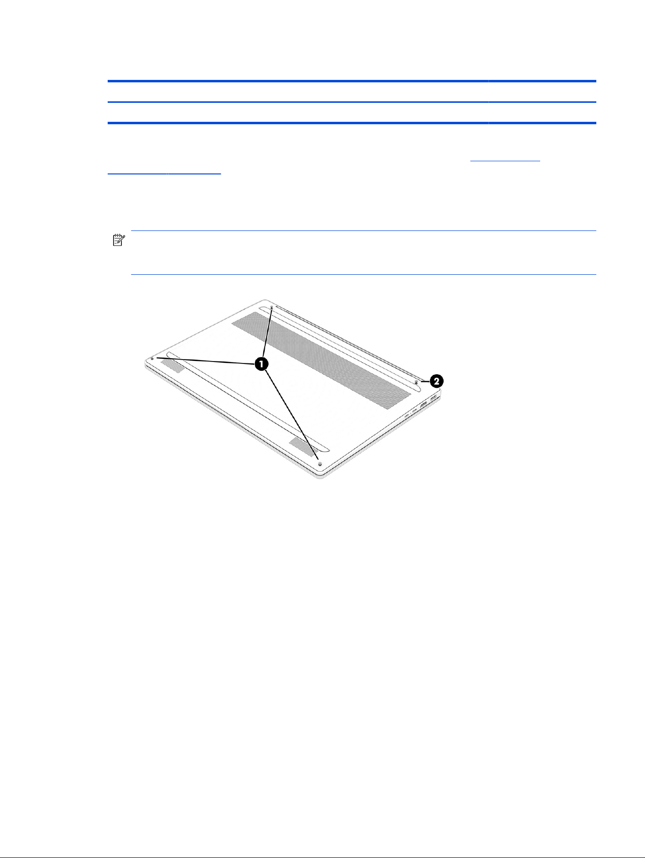
Table 5-1 Bottom cover description and part number (continued)
Description Spare part number
Bottom cover (starlit blue) P83606-001
Before removing the bottom cover, prepare the computer for disassembly (see Preparation for
disassembly on page 30).
Remove the bottom cover:
1. Remove the four Phillips M2.0 × 4.0 screws that secure the bottom cover to the computer.
NOTE: The bottom cover includes three non-captive screws (1) and one captive (not removable)
screw (2) that causes the cover to pop up when you loosen the screw. After the cover pops up, do
not continue to loosen the captive screw.
2. Use a nonmarking, nonconductive tool (1) to release the edges of the bottom cover from the
computer.
Bottom cover
31
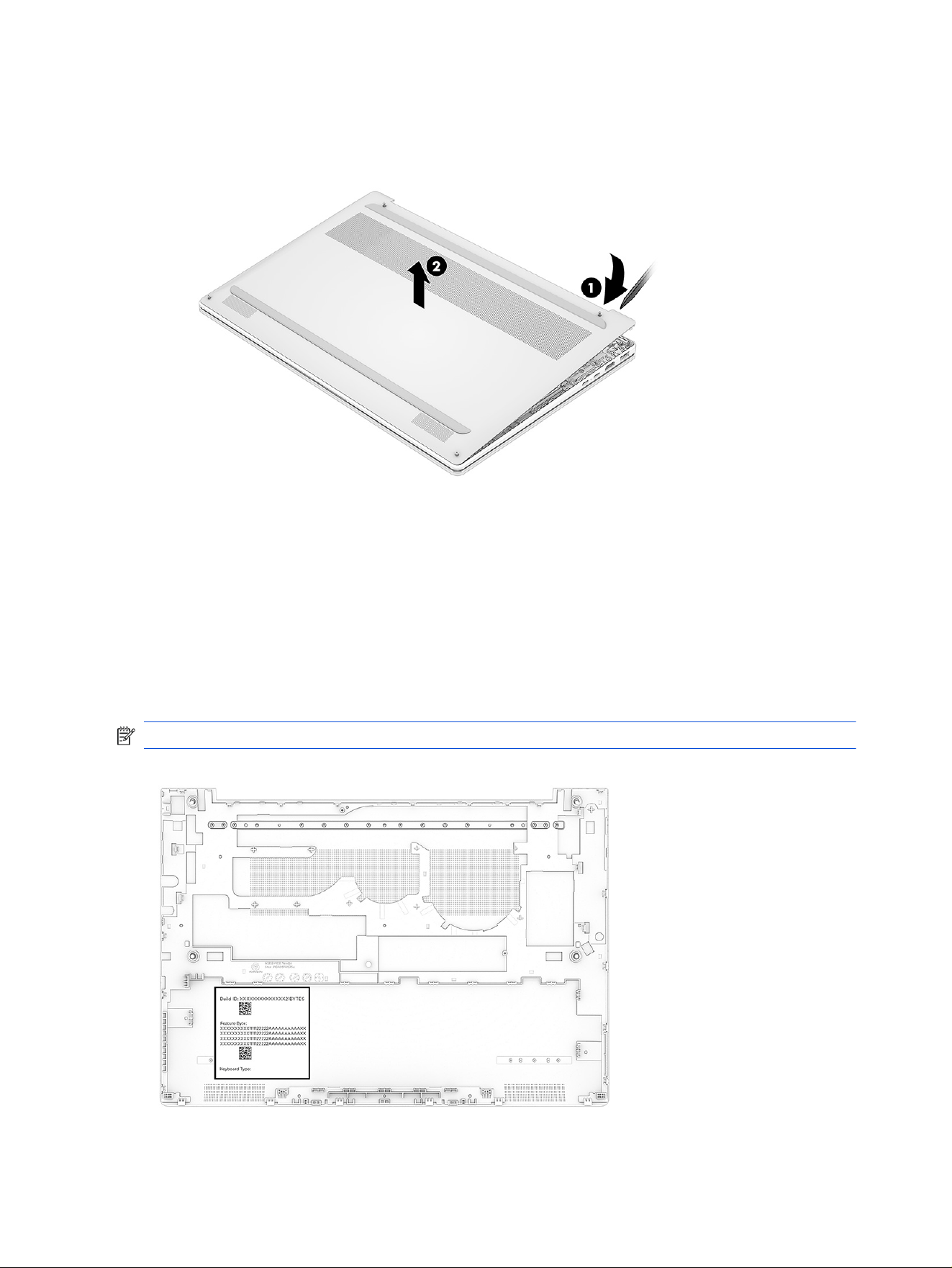
3. Remove the bottom cover (2) from the computer.
Reverse the removal procedures to replace the bottom cover.
When replacing the bottom cover, remove the Feature Byte label from the inside of the old bottom cover
and place it on the inside of the new bottom cover. Be sure to keep this label with the computer, because
the label is required for any future repairs.
You can locate product labels:
● Laser etched on the old bottom cover.
● In HP System Information by pressing fn + esc when you turn on the computer.
NOTE: Bottom cover appearance might vary.
32
Chapter 5 Removal and replacement procedures for Customer Self-Repair parts
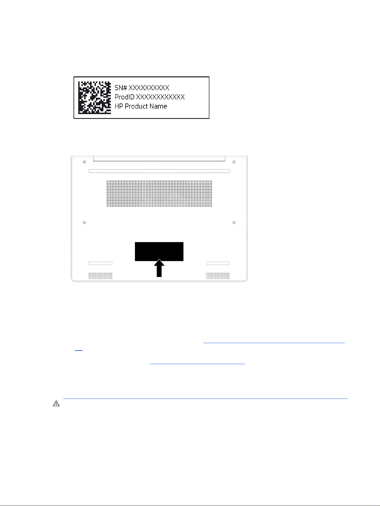
Hand write the product information onto the label of the new bottom cover. Use a ballpoint pen or marker
to avoid smudging.
Example of label information
New bottom cover label location
Battery
The battery removal procedure differs depending on whether you are removing and replacing the existing
battery or installing a new battery. To install a new battery, you must use a revive kit.
● To remove and replace the existing battery, see Removing and reinstalling the same battery on page
33.
● To install a new battery, see Installing a new battery on page 35.
Removing and reinstalling the same battery
Use this procedure and illustration to remove the battery.
WARNING! To avoid personal injury and damage to the product:
● Do not puncture, twist, or crack the battery.
● Do not cause an external puncture or rupture to the battery, which can cause a short inside the
battery that can result in battery thermal runaway.
Battery
33
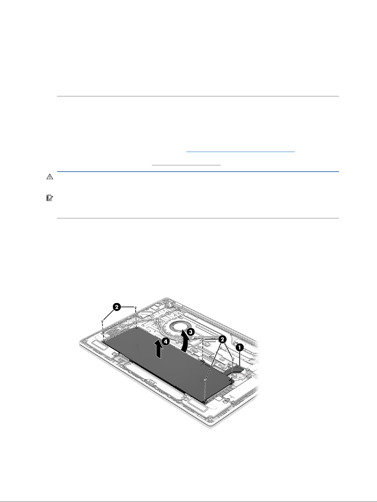
● Do not handle or touch the battery enclosure with sharp objects such as tweezers or pliers, which
might puncture the battery.
● Do not compress or squeeze the battery case with tools or heavy objects stacked on top of the
case. These actions can apply undue force on the battery.
● Do not touch the connectors with any metallic surface or object, such as metal tools, screws, or
coins, which can cause shorting across the connectors.
For additional battery information, see the Regulatory, Safety, and Environmental Notices. To access this
guide, select the Search icon in the taskbar, type HP Documentation in the search box, and then select
HP Documentation.
Before removing the battery, follow these steps:
1. Prepare the computer for disassembly (see Preparation for disassembly on page 30).
2. Remove the bottom cover (see Bottom cover on page 30).
WARNING! To reduce potential safety issues, use only the user-replaceable battery provided with the
computer, a replacement battery provided by HP, or a compatible battery purchased from HP.
IMPORTANT: Removing a battery that is the sole power source for the computer can cause loss of
information. To prevent loss of information, save your work or shut down the computer through Windows
before you remove the battery.
Remove the battery:
1. Disconnect the battery cable (1) from the system board.
2. Remove the ve Phillips M2.0 × 4.0 screws (2) that secure the battery to the computer.
3. Tilt the battery away from the computer (3).
4. Remove the battery from the computer (4).
34
Chapter 5 Removal and replacement procedures for Customer Self-Repair parts

Reverse this procedure to install the battery.
NOTE: When reinstalling the battery, be sure to completely reassemble the computer and plug in the
AC adapter before turning the computer on. In addition, the battery cable has two different connectors:
the black connector is attached to the battery and the white connector is attached to the system board.
Installing a new battery
Use this procedure and illustrations to install the battery. You must use a revive kit to remove the old
battery and install a new one. The revive kit includes an empty containment tray and a containment tray
with a battery preinstalled.
Table 5-2 Battery description and part number
Description Spare part number
4 cell, 68 Whr, polymer, HP Long Life P13980-001
Before starting this replacement procedure:
● Ensure other individuals are sufciently clear of your workspace.
● Ensure your workspace is clear of any ammable material such as paper or oils.
● Locate the nearest ABC dry chemical re extinguisher for use in an emergency.
WARNING! This procedure requires removing the battery or disconnecting the battery cable. Use care
to avoid bending, twisting, or puncturing the battery regardless of its condition. Failure to follow this
replacement guide or to use HP recommended tools might damage the system and/or cause a safety
hazard.
● Do not remove the battery from the containment tray.
● Do not handle or touch the battery enclosure with sharp objects such as tweezers or pliers, which
might puncture the battery.
● Do not touch the connectors with any metallic surface or object, such as metal tools, screws, or
coins, which can cause shorting across the connectors.
Should a part become stuck or difcult to remove when opening a unit where a swollen battery is
suspected, or if the battery becomes stuck in the unit, stop and contact HP Support for assistance. Do not
try to remove a battery by force.
NOTE: Screw locations, latch locations, and internal components might vary.
Before removing the battery, follow these steps:
1. Prepare the computer for disassembly (see Preparation for disassembly on page 30).
Installing a new battery
35
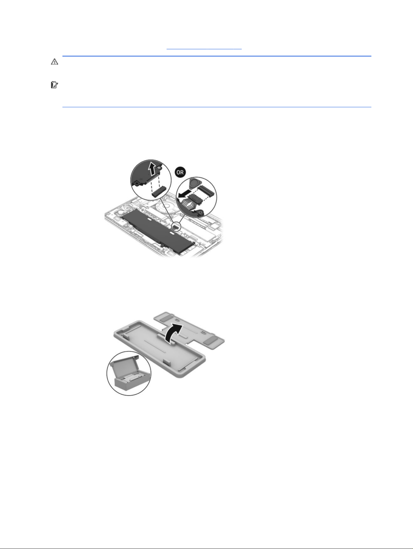
2. Remove the bottom cover (see Bottom cover on page 30).
WARNING! To reduce potential safety issues, use only the user-replaceable battery provided with the
computer, a replacement battery provided by HP, or a compatible battery purchased from HP.
IMPORTANT: Removing a battery that is the sole power source for the computer can cause loss of
information. To prevent loss of information, save your work or shut down the computer through Windows
before you remove the battery.
1. Remove the battery using the revive kit:
a. Disconnect the battery cable from the system board. The connector location might vary.
b. Open the empty battery containment tray.
36
Chapter 5 Removal and replacement procedures for Customer Self-Repair parts
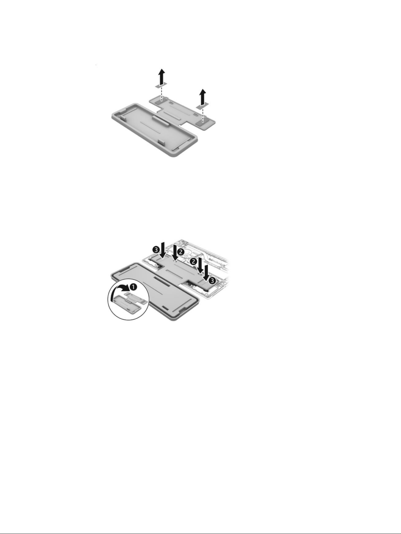
c. Remove the paper backing layer from the adhesive on the tray.
d. Turn the tray (1) over so that the adhesive is facing down.
e. Place the tray (2) centered on the battery.
f. Press down on the indentations on the tray (3) to adhere it to the battery.
g. Remove the Phillips screws (1) that secure the battery to the computer. Number of screws and
screw locations might vary.
Installing a new battery
37
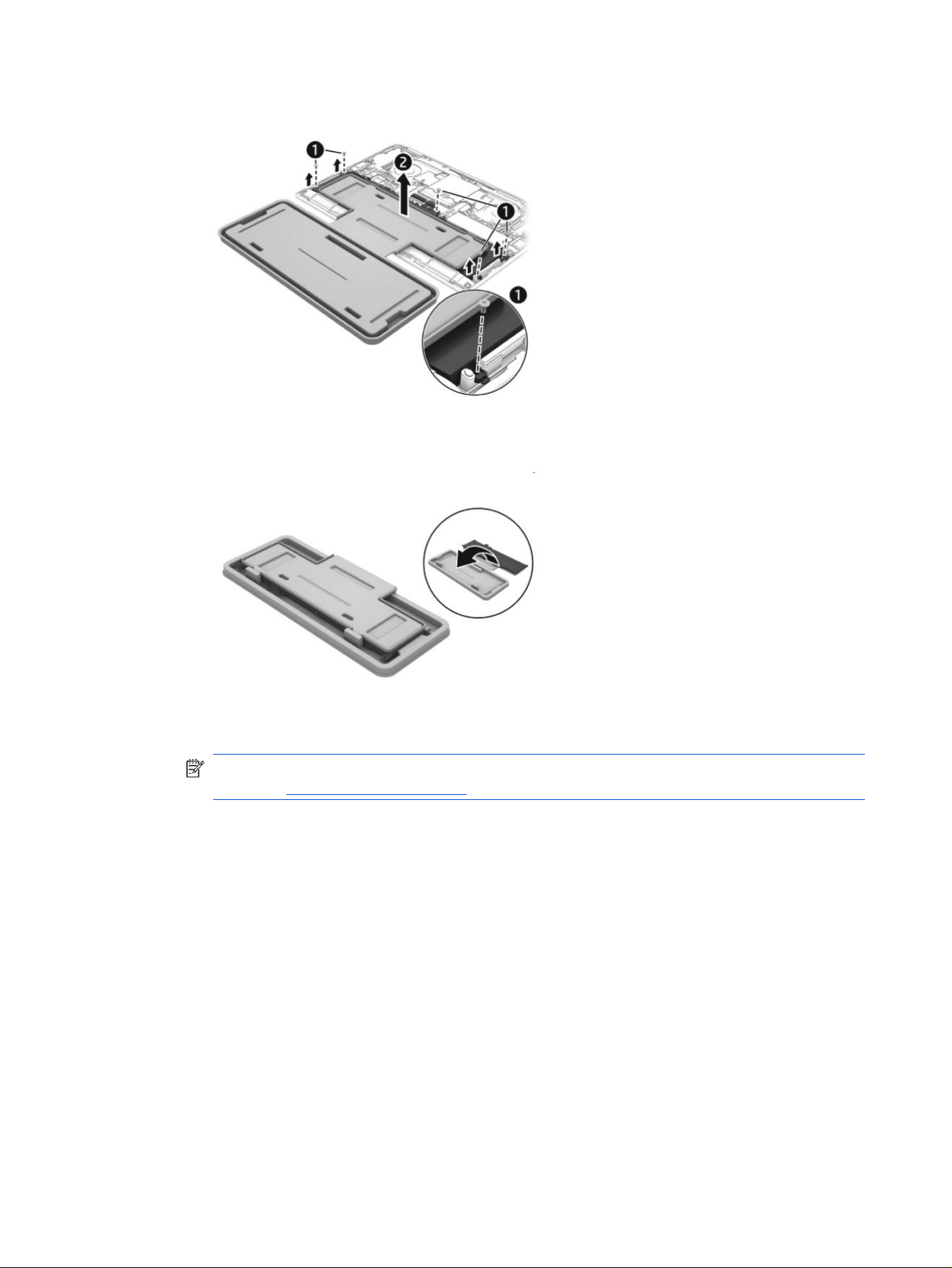
h. Lift the top of the tray (2) to remove the battery from the computer.
i. Rotate the battery up and over into the cavity of the containment tray.
NOTE: Please recycle responsibly. For more information about recycling programs, see the HP
website at http://www.hp.com/recycle.
2. Install the battery using the revive kit:
a. Open the containment tray that includes the new battery.
38
Chapter 5 Removal and replacement procedures for Customer Self-Repair parts
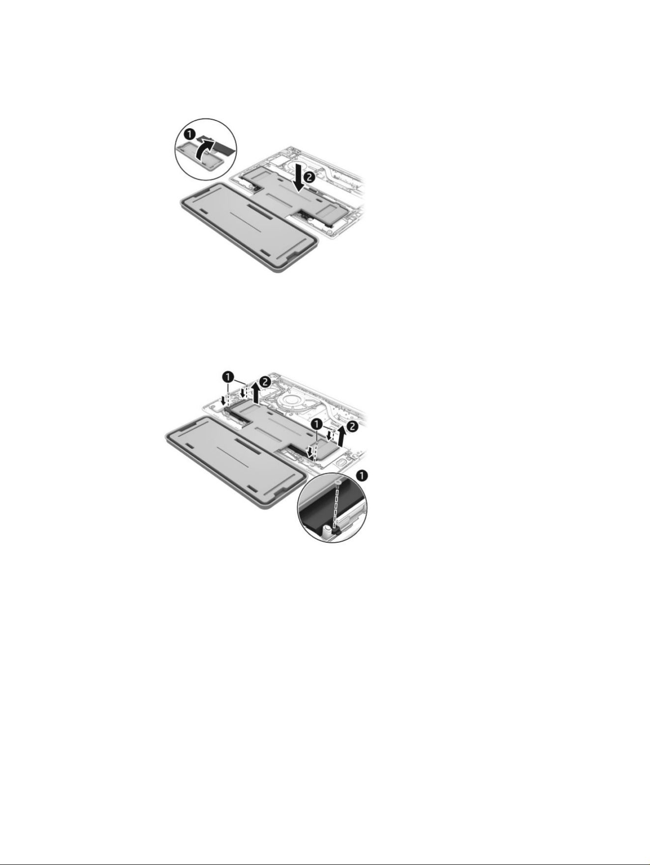
b. Turn the tray (1) over so the battery is facing downward, and then insert the battery (2) into the
computer. Adhesive secures the battery to the tray.
c. Install the Phillips screws (1) to secure the battery. Number of screws and screw locations might
vary.
d. Lift the containment tray (2) off the battery.
Installing a new battery
39
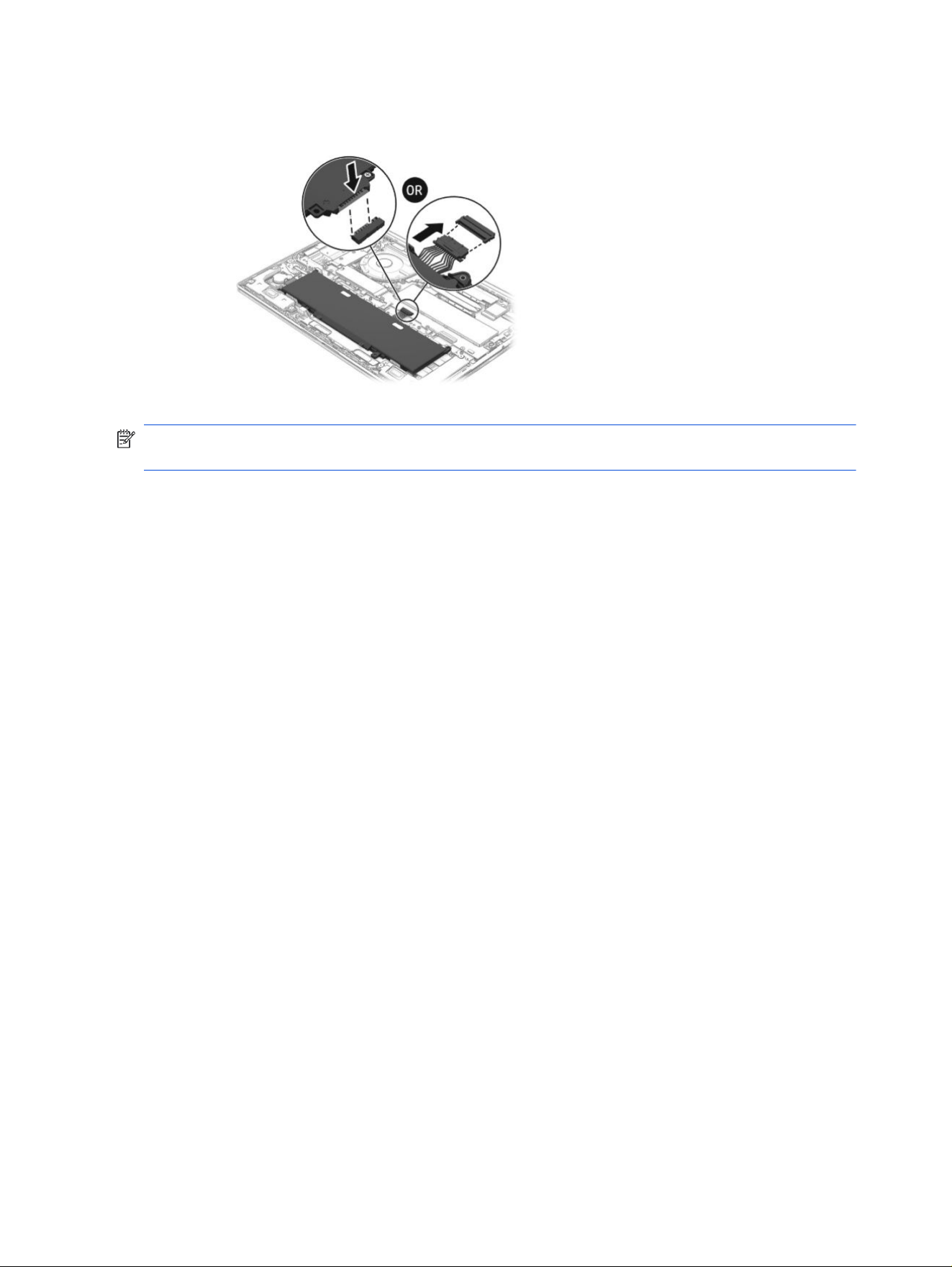
e. Connect the battery cable to the system board. The connector location might vary.
NOTE: When replacing the battery, be sure to completely reassemble the computer and plug in the AC
adapter before turning the computer on.
40
Chapter 5 Removal and replacement procedures for Customer Self-Repair parts

Removal and replacement procedures
for authorized service provider parts
6
This chapter provides removal and replacement procedures for authorized service provider parts.
IMPORTANT: Only an authorized service provider should access the components described in this
chapter. Accessing these parts can damage the computer or void the warranty.
NOTE: Details about your computer, including model, serial number, product key, and length of
warranty, are on the service tag at the bottom of your computer.
NOTE: The HP Support YouTube Channel (in English) has videos that provide step-by-step removal and
replacement instructions for many common parts and models.
Component replacement procedures
Use the procedures described in this section to remove and replace computer components.
NOTE: HP continually improves and changes product parts. For complete and current information
about supported parts for your computer, go to https://partsurfer.hp.com/, select your country or region,
and then follow the on-screen instructions.
Make special note of each screw size and location during removal and replacement.
Speakers
Use this procedure and illustration to remove the speakers.
Table 6-1
Speaker description and part number
Description Spare part number
Speaker Kit P83621-001
Before removing the speakers, follow these steps:
1. Prepare the computer for disassembly (see Preparation for disassembly on page 30).
2. Remove the bottom cover (see Bottom cover on page 30).
Remove the speakers:
1. Disconnect the speaker cable from the system board (1).
2. Remove the cable from the clips beside the battery (2).
3. Remove the cable from the clips below the battery (3).
4. Remove the two Phillips M2.0 × 4.0 screws (4) that secure each speaker to the computer.
Removal and replacement procedures for authorized service provider parts
41
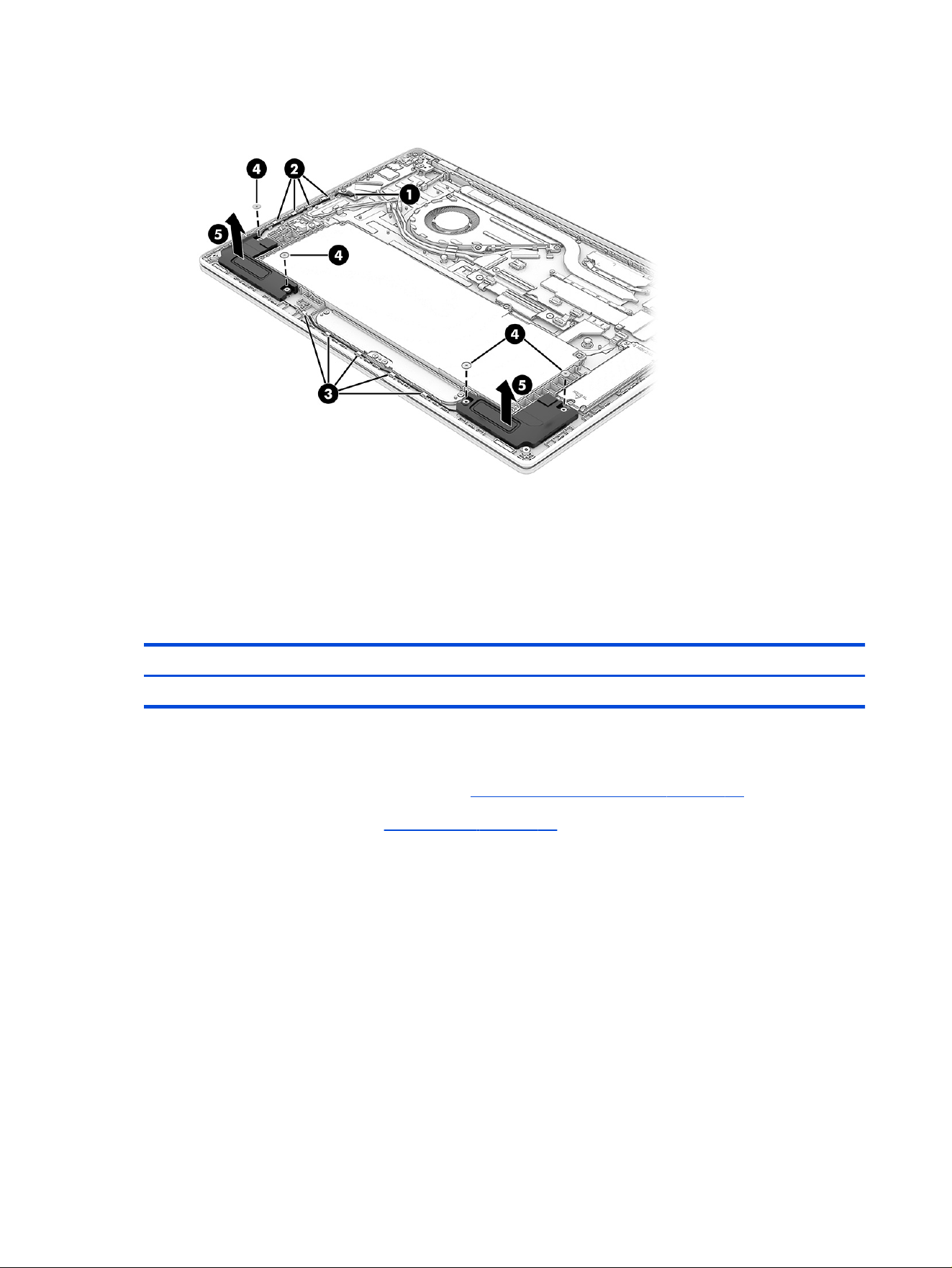
5. Remove the speakers (5) from the computer.
Reverse this procedure to install the speakers.
Transition board
Use this procedure and illustration to remove the transition board.
Table 6-2
Transition board description and part number
Description Spare part number
Transition board with cable P83617-001
Before removing the transition board, follow these steps:
1. Prepare the computer for disassembly (see Preparation for disassembly on page 30).
2. Remove the bottom cover (see Bottom cover on page 30).
Remove the transition board:
1. Disconnect the power cable from the transition board ZIF connector (1).
2. Disconnect the cable from the system board ZIF connector (2).
3. Remove the two Phillips M2.0 × 3.0 screws (3) that secure the board to the computer.
4. Disconnect the keyboard cable from the transition board ZIF connector (4).
5. Disconnect the keyboard backlight cable from the transition board ZIF connector (5).
42
Chapter 6 Removal and replacement procedures for authorized service provider parts
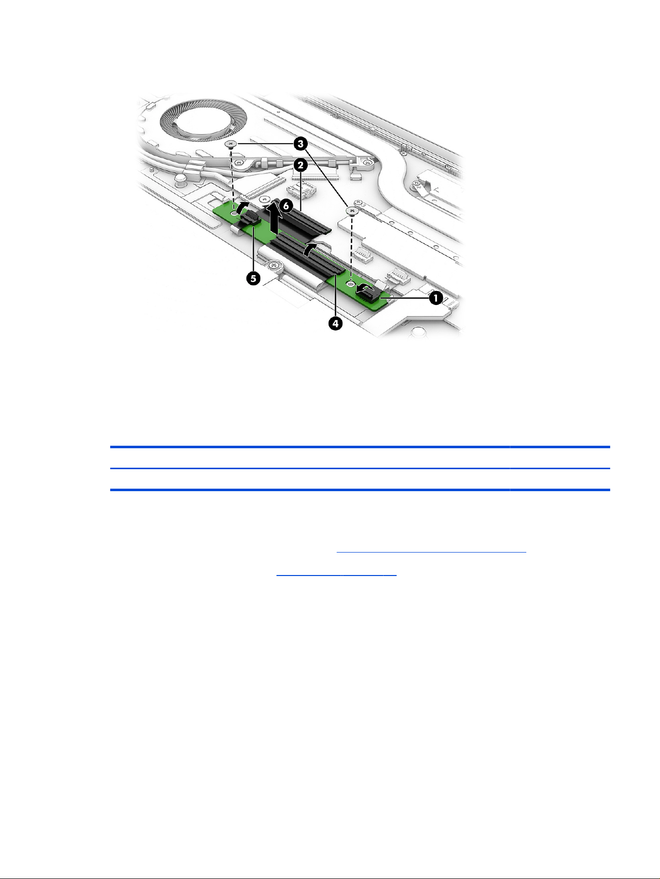
6. Remove the board (6) from the computer.
Reverse this procedure to install the transition board.
OLED power management board
Use this procedure and illustration to remove the OLED power management board.
Table 6-3
OLED power management board description and part number
Description Spare part number
Power management board with cable P83616-001
Before removing the power management board, follow these steps:
1. Prepare the computer for disassembly (see Preparation for disassembly on page 30).
2. Remove the bottom cover (see Bottom cover on page 30).
3. Disconnect the battery cable from the system board.
Remove the power management board:
1. Disconnect the cable from the ZIF connector (1).
2. Remove the Phillips M2.0 × 3.0 screw (2) that secures the board to the computer.
OLED power management board
43
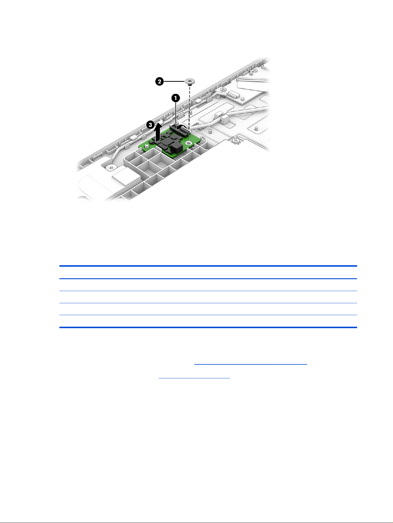
3. Remove the board (3) from the computer.
Reverse this procedure to install the power management board.
Solid-state drive
Use this procedure and illustration to remove the SSD.
Table 6-4
SSD descriptions and part numbers
Description Spare part number
1 Tb PCIe 5×4 Non-Volatile Memory Express (NVMe) P73030-005
1 Tb PCIe NVMe N77394-005
512 GB PCIe 5×4 NVMe P73029-005
512 GB PCIe NVMe N77392-005
Before removing the SSD, follow these steps:
1. Prepare the computer for disassembly (see Preparation for disassembly on page 30).
2. Remove the bottom cover (see Bottom cover on page 30).
3. Disconnect the battery cable from the system board.
Remove the SSD:
1. Remove the two Phillips M2.0 × 2.5 screws (1) that secure the drive cover to the computer.
2. Remove the drive cover (2).
44
Chapter 6 Removal and replacement procedures for authorized service provider parts
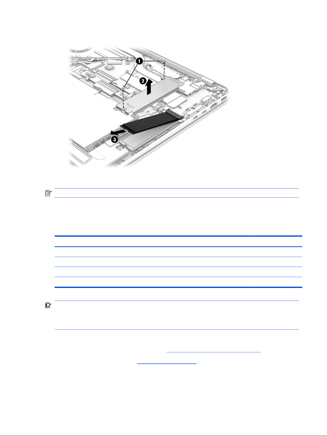
3. Pull the drive (3) away from the socket to remove it.
Reverse this procedure to install the SSD.
NOTE: SSDs are designed with a notch to prevent incorrect insertion.
WLAN module
Use this procedure and illustrations to install the WLAN module.
Table 6-5
WLAN module descriptions and part numbers
Description Spare part number
Intel BE211 with Bluetooth 6.0, M.2 2230, non-vPro P36621-005
Intel AX8922AE with Bluetooth 5.4, M.2 2230 P44408-005
MediaTek MT7920 with Bluetooth 5.4, Wi-Fi 6, M.2 2230 P17386-005
Realtek RTL8852BE with Bluetooth 5.4, M.2 2230 P06350-005
IMPORTANT: To prevent an unresponsive system, replace the wireless module only with a wireless
module authorized for use in the computer by the governmental agency that regulates wireless devices
in your country or region. If you replace the module and then receive a warning message, remove the
module to restore device functionality, and then contact technical support.
Before removing the WLAN module, follow these steps:
1. Prepare the computer for disassembly (see Preparation for disassembly on page 30).
2. Remove the bottom cover (see Bottom cover on page 30).
3. Disconnect the battery cable from the system board.
Remove the WLAN module:
WLAN module
45
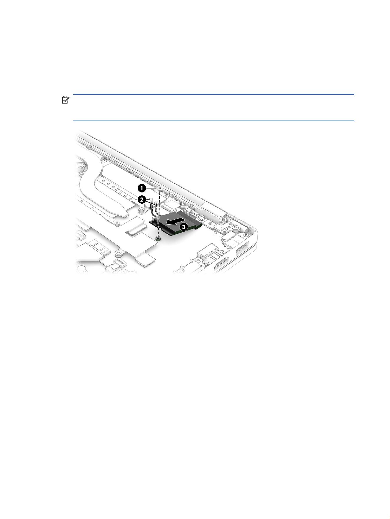
1. Remove the plastic cover over the WLAN module.
2. Remove the Phillips M2.0 × 2.5 screw (1).
3. Carefully disconnect the two antenna cables (2) from the module.
4. Remove the WLAN module (3).
NOTE: Models have either one or two WLAN antennas. On models with two antennas, the #1 white
WLAN antenna cable connects to the WLAN module #1 Main terminal. The #2 black WLAN antenna
cable connects to the WLAN module #1 Aux terminal.
5. Thoroughly clean the thermal material from the surfaces of the WLAN module and the system board
components each time the WLAN module is removed. Replacement thermal material is included with
the WLAN module and system board spare part kits. The following illustration shows the replacement
thermal material location.
46
Chapter 6 Removal and replacement procedures for authorized service provider parts
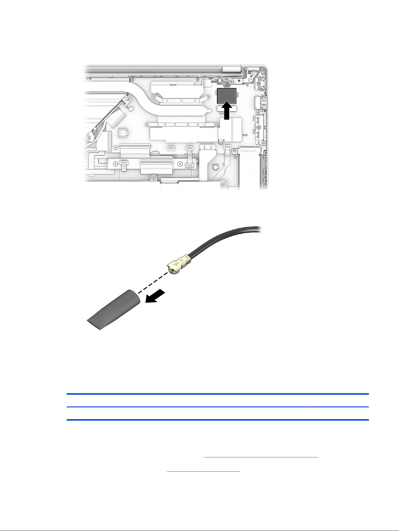
6. If the WLAN antenna is not connected to the terminal on the WLAN module, install a protective sleeve
on the antenna connector, as shown in the following illustration.
Reverse this procedure to install the WLAN module.
Fan
Use this procedure and illustration to remove the fan.
Table 6-6
Fan description and part number
Description Spare part number
Fan assembly P83622-001
Before removing the fan, follow these steps:
1. Prepare the computer for disassembly (see Preparation for disassembly on page 30).
2. Remove the bottom cover (see Bottom cover on page 30).
Fan
47
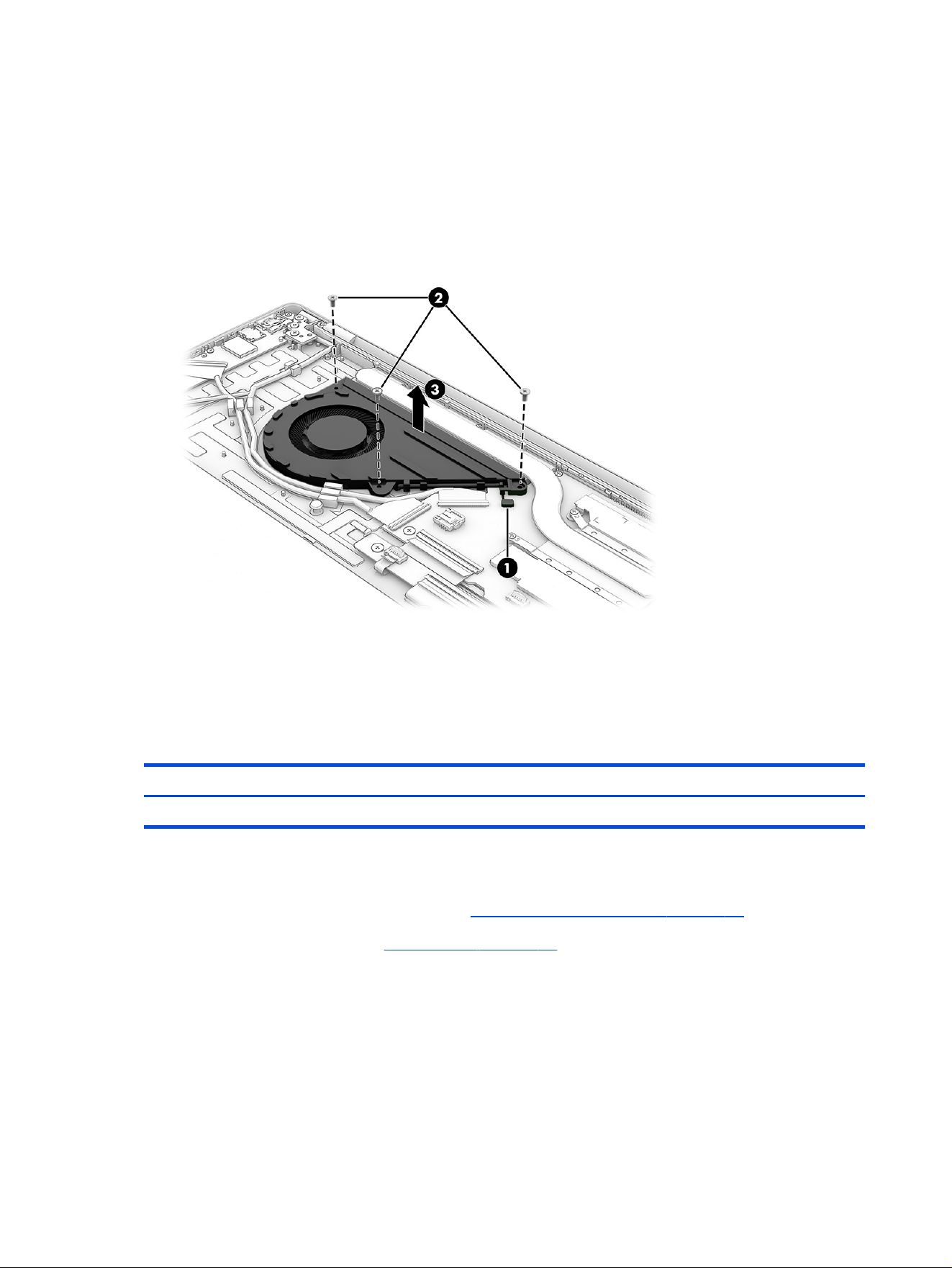
3. Disconnect the battery cable from the system board.
Remove the fan assembly:
1. Disconnect the fan cable (1) from the system board.
2. Remove the three Phillips M2.0 × 5.0 screws (2) that secure the fan to the computer, and then remove
the fan (3) from the computer.
Reverse this procedure to install the fan.
USB board
Use this procedure and illustrations to remove the USB board.
Table 6-7
USB board description and part number
Description Spare part number
USB board with cable P83615-001
Before removing the USB board, follow these steps:
1. Prepare the computer for disassembly (see Preparation for disassembly on page 30).
2. Remove the bottom cover (see Bottom cover on page 30).
3. Disconnect the battery cable from the system board.
Remove the USB board:
1. Disconnect the cable from the USB board ZIF connector (1) and the system board ZIF connector (2).
48
Chapter 6 Removal and replacement procedures for authorized service provider parts
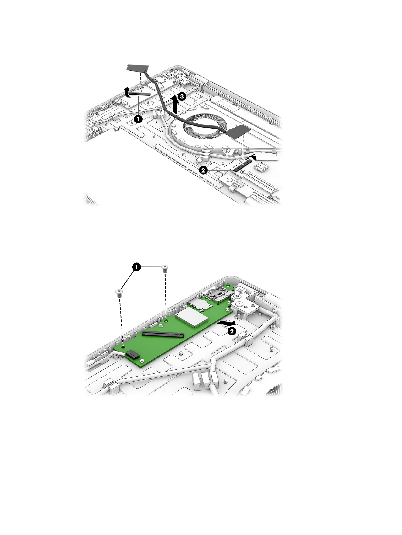
2. Remove the USB board cable (3).
3. Remove the two Phillips M2.0 × 3.0 screws (1) that secure the board to the computer.
4. Remove the board (2) from the computer.
Reverse this procedure to install the USB board.
Touchpad
Use this procedure and illustrations to remove the touchpad.
Touchpad
49
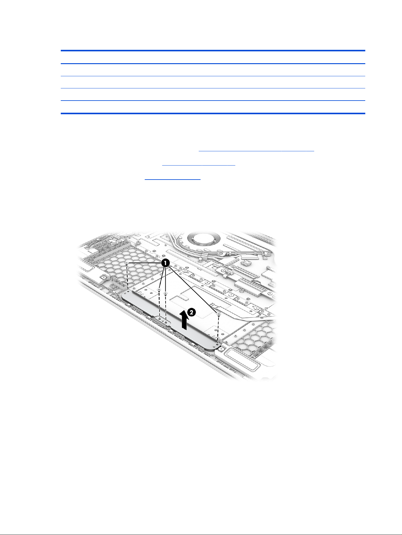
Table 6-8 Touchpad description and part number
Description Spare part number
Touchpad (glacier silver) P83628-001
Touchpad (meteor silver) P83629-001
Touchpad (silk sand) P83630-001
Touchpad (starlit blue) P83631-001
Before removing the touchpad, follow these steps:
1. Prepare the computer for disassembly (see Preparation for disassembly on page 30).
2. Remove the bottom cover (see Bottom cover on page 30).
3. Remove the battery (see Battery on page 33).
Remove the touchpad:
1. Remove the four Phillips M2.0 × 3.0 screws (1) that secure the touchpad bracket to the computer.
2. Remove the touchpad bracket from the computer (2).
3. Disconnect the cable from the ZIF connector (1) on the system board.
4. Remove the four Phillips M2.0 × 3.0 screws (2) that secure the touchpad to the computer.
50
Chapter 6 Removal and replacement procedures for authorized service provider parts
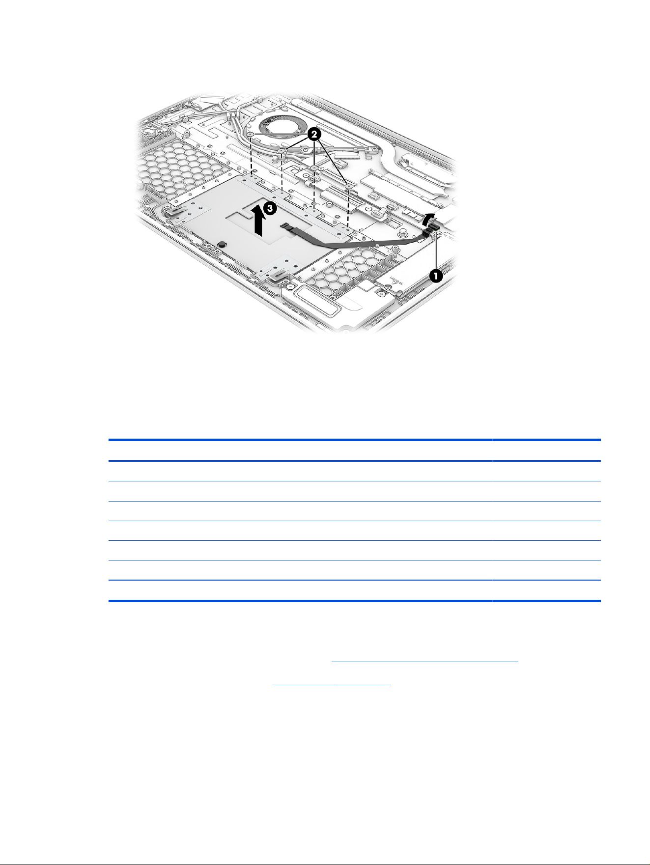
5. Remove the touchpad (3) from the computer.
Reverse this procedure to install the touchpad.
Heat sink
Use this procedure and illustrations to remove the heat sink.
Table 6-9
Heat sink descriptions and part numbers
Description Spare part number
For use in models with AMD Processors:
For use in models with an AMD Ryzen AI 9 465 processor P83625-001
For use in models with an AMD Ryzen AI 7 445 processor P83627-001
For use in models with an AMD Ryzen AI 5 430 or AMD Ryzen 7 250 processor P83626-001
For use in models with Intel Processors:
Heat sink for use in models with Intel Core Ultra 5, 7, and 9 processors P83624-001
Heat sink for use in models with Intel Core 5 and 7 processors P83623-001
Before removing the heat sink, follow these steps:
1. Prepare the computer for disassembly (see Preparation for disassembly on page 30).
2. Remove the bottom cover (see Bottom cover on page 30).
3. Disconnect the battery cable from the system board.
4. Remove the Mylar cover over the heat sink and system board.
Remove the heat sink:
Heat sink
51
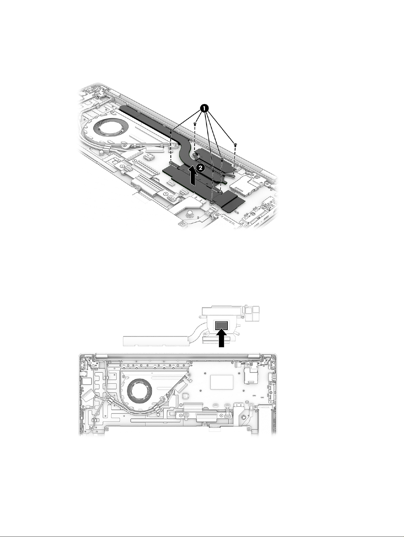
1. In the order indicated on the heat sink, remove the ve Phillips M2.0 × 4.0 screws (1) that secure the
heat sink to the computer.
2. Remove the heat sink (2) from the computer.
3. Thoroughly clean the thermal material from the surfaces of the heat sink and the system board
components each time the heat sink is removed. Replacement thermal material is included with the
heat sink and system board spare part kits. The following illustration shows the replacement thermal
material location.
Reverse this procedure to install the heat sink.
System board
Use this procedure and illustrations to remove the system board.
52
Chapter 6 Removal and replacement procedures for authorized service provider parts

Table 6-10 System board descriptions and part numbers
Description Spare part number
System board (includes AMD processor):
AMD Ryzen AI 9 465(32 GB) P83638-601
AMD Ryzen AI 9 465 (32 GB, PRC) P83643-601
AMD Ryzen AI 7 445 (32 GB) P83637-601
AMD Ryzen AI 7 445 (32 GB, PRC) P83642-601
AMD Ryzen AI 7 445 (24 GB) Q12513-601
AMD Ryzen AI 7H 445 (24 GB, PRC) Q12514-601
AMD Ryzen AI 7 445 (16 GB) P83636-601
AMD Ryzen AI 7 445 (16 GB, PRC) P83641-601
AMD Ryzen AI 5 430 (16 GB) P83639-601
AMD Ryzen AI 5 430 (16 GB, PRC) P83640-601
AMD Ryzen AI 5 330 (32 GB) Q06472-601
AMD Ryzen AI 5 330 (32 GB, PRC) Q06473-601
AMD Ryzen AI 5 330 (24 GB) Q12511-601
AMD Ryzen AI 5 330 (24 GB, PRC) Q12512-601
AMD Ryzen AI 5 330 (16 GB) Q06470-601
AMD Ryzen AI 5 330 (16 GB, PRC) Q06471-601
AMD Ryzen 7 250 (32 GB) P83646-601
AMD Ryzen 7 250 (32 GB, PRC) P83647-601
AMD Ryzen 7 250 (16 GB) P83644-601
AMD Ryzen 7 250 (16 GB, PRC) P83645-601
AMD Ryzen 5 230 (16 GB) P83648-601
AMD Ryzen 5 230 (16 GB, PRC) P83649-601
System board (includes Intel processor):
Intel Core Ultra 9 386H processor, 32 GB P83593-601
Intel Core Ultra 7 355 processor, 32 GB P83592-601
Intel Core Ultra 7 355 processor, 16 GB P83591-601
Intel Core 7 150U processor, 16 GB P83594-601
Intel Core Ultra 5 322 processor, 24 GB Q12510-601
Intel Core Ultra 5 322 processor, 16 GB P83590-601
Intel Core Ultra 5 120U processor, 16 GB P83589-601
Intel Core i7 350 processor, 24 GB Q15982-601
Intel Core i5 320 processor, 16 GB Q08416-601
Intel Core i5 320 processor, 32 GB Q08415-601
System board 53

Table 6-10 System board descriptions and part numbers (continued)
Description Spare part number
Intel Core i5 320 processor, 24 GB Q15981-601
Intel Core i5 processor, 16 GB P83589-601
Before removing the system board, follow these steps:
1. Prepare the computer for disassembly (see Preparation for disassembly on page 30).
2. Remove the bottom cover (see Bottom cover on page 30).
3. Disconnect the battery cable from the system board.
4. Remove the fan (see Fan on page 47).
5. Remove the SSD (see Solid-state drive on page 44).
6. WLAN module (see WLAN module on page 45).
7. Heat sink (see Heat sink on page 51).
Remove the system board:
1. Disconnect the following cables from the system board:
● Camera cable (ZIF) (1)
● Touchpad cable (ZIF) (2)
● Transition board cable (ZIF) (3)
● Keyboard cable (ZIF) (4)
● Keyboard backlight cable (ZIF) (5)
● USB board cable (ZIF) (6)
● Embedded DisplayPort (eDP) cable (ZIF) (7)
54
Chapter 6 Removal and replacement procedures for authorized service provider parts
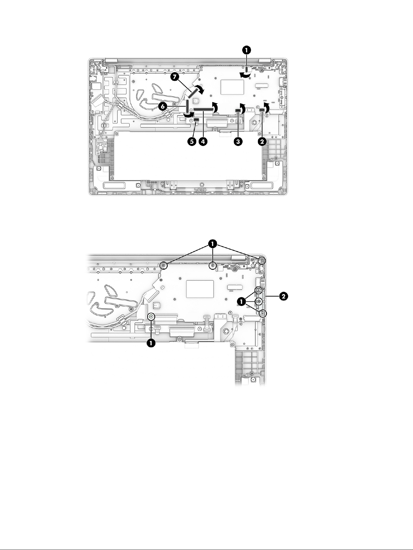
2. Remove the seven Phillips M2.0 × 5.0 screws (1) that secure the system board to the computer, and
then pull the system board into the computer slightly to release it from the top cover (2).
System board
55
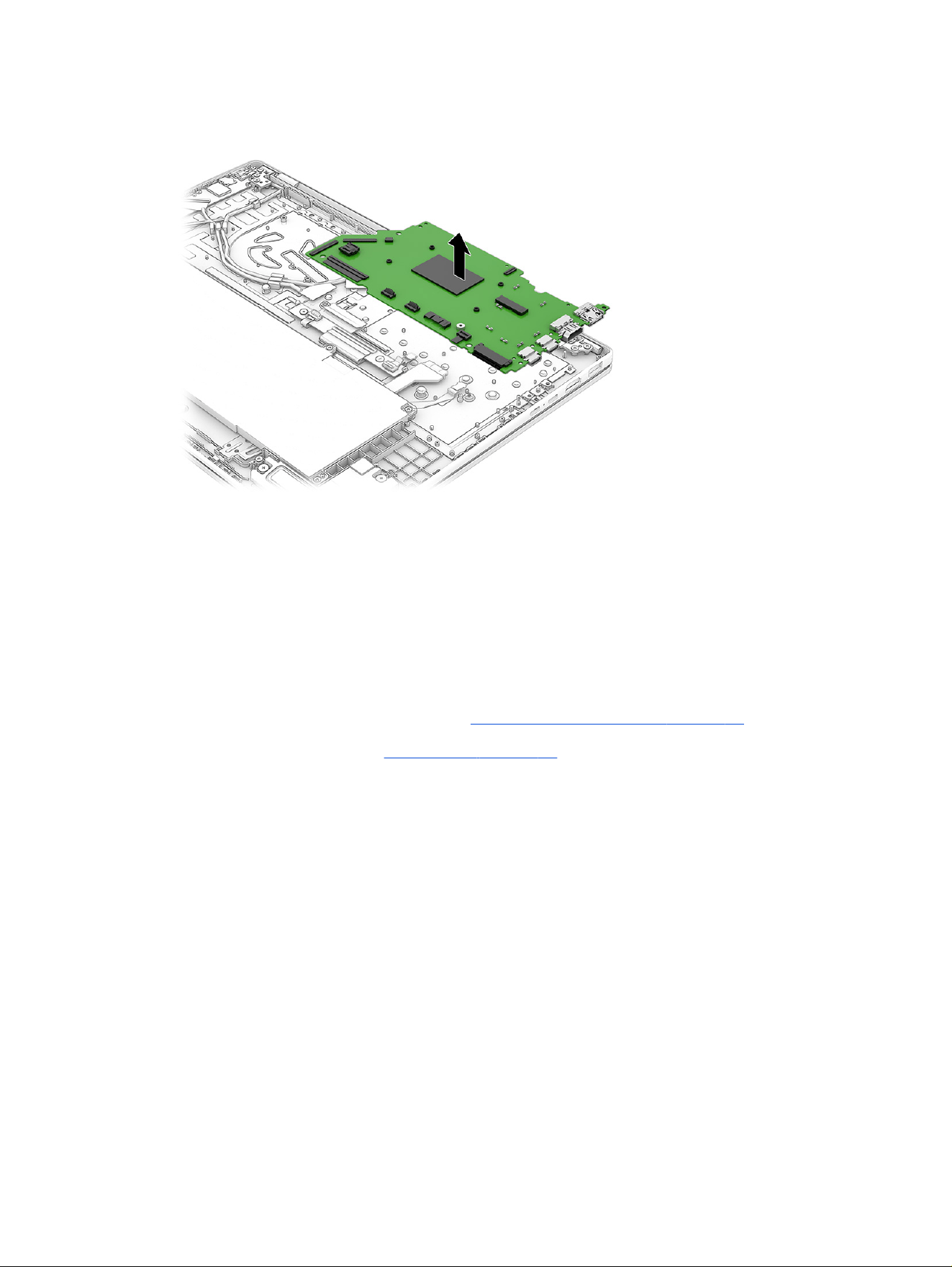
3. Remove the system board from the computer.
Reverse this procedure to install the system board.
Display assembly
Use this procedure and illustrations to remove and disassemble the display assembly.
Full hinge-up displays are not available as spare parts. Spare parts for displays are available only at the
subcomponent level.
Before removing the display panel, follow these steps:
1. Prepare the computer for disassembly (see Preparation for disassembly on page 30).
2. Remove the bottom cover (see Bottom cover on page 30).
Remove the display assembly:
1. Remove the Mylar cover (1).
2. Remove the WLAN module cover (2).
3. Disconnect the battery cable from the system board.
4. Disconnect the following cables from the system board:
● WLAN module cables (3)
● Camera cable (4)
● Embedded DisplayPort (eDP) cable (5)
● Power management cable (6)
Display panel cables are available with the following spare part numbers for computers with AMD
processors:
56
Chapter 6 Removal and replacement procedures for authorized service provider parts
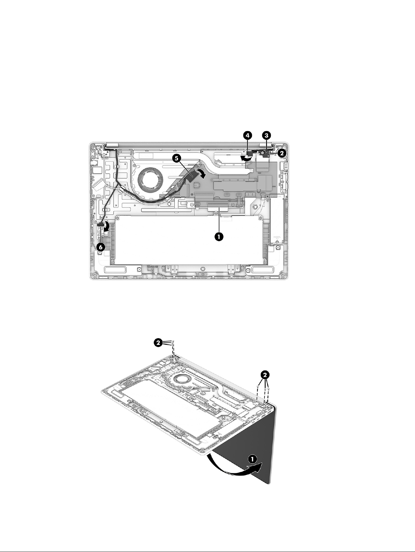
● P83929-001: Display cable only
● P83619-001: Cable kit with antenna
Display panel cables are available with the following spare part numbers for computers with Intel
processors:
● P83618-001: Display cable only
● P83619-001: Cable kit with antenna
5. Rotate the display (1) upward to open the hinges, and then place the display on the edge of a table or
other surface to avoid damaging the hinges or other parts during removal.
6. Remove the six Phillips M2.5 × 5.0 screws (2) that secure the display assembly to the computer.
Display assembly
57
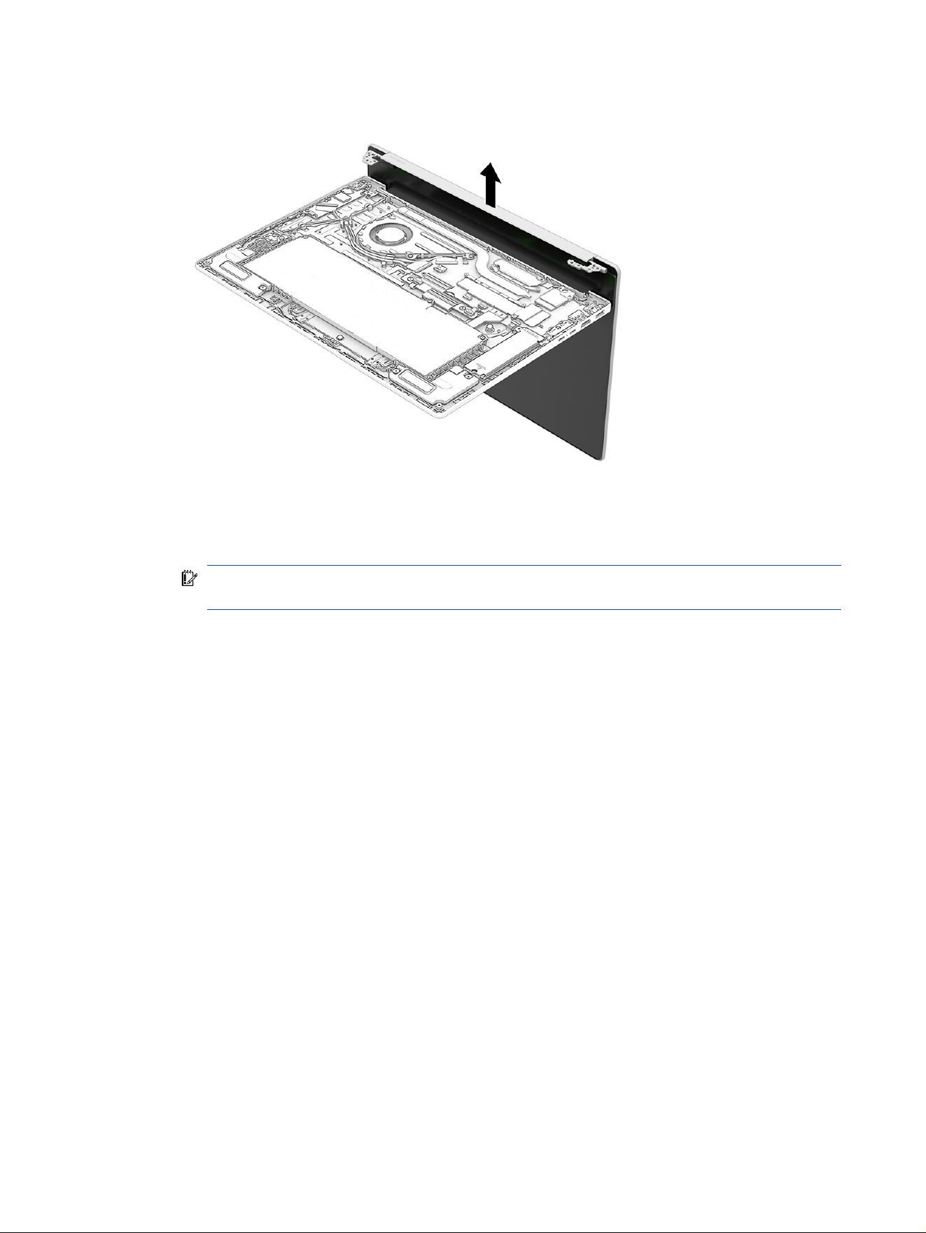
7. Separate the display assembly from the computer.
8. To replace display assembly subcomponents:
a. With a heat gun (1), use the following steps to heat the panel.
IMPORTANT: Maintain a distance of 4 inches (10 cm) between the heat gun and the surface to
prevent bezel or panel damage.
i. Set the heat gun temperature to 150℉.
ii. Apply heat evenly around the bezel for 20-30 seconds.
iii. For computers with a touchscreen, peel off the bezel and use care to pull the adhesive bar
to remove it for disassembly.
iv. For computers without a touchscreen, turn the bezel over and remove it for disassembly.
b. Slide a at tool (2) across the inside of the bottom of the bezel to release it.
c. The display panel is secured to the display enclosure with tape that is installed under the left
and right sides of the panel. To remove the panel, use tweezers to grasp the end of the tape (3).
While turning the tweezers, wrap the tape around the tweezers as you continue to pull the tape
out from behind the display panel. You must pull the tape multiple times before it is completely
removed.
d. Remove the panel (4) from the display.
Display panels are available as the following spare part numbers:
● P83597-001: 2.8K OLED
● P83598-001: FHD touchscreen
● P83596-001: FHD non-touchscreen
58
Chapter 6 Removal and replacement procedures for authorized service provider parts
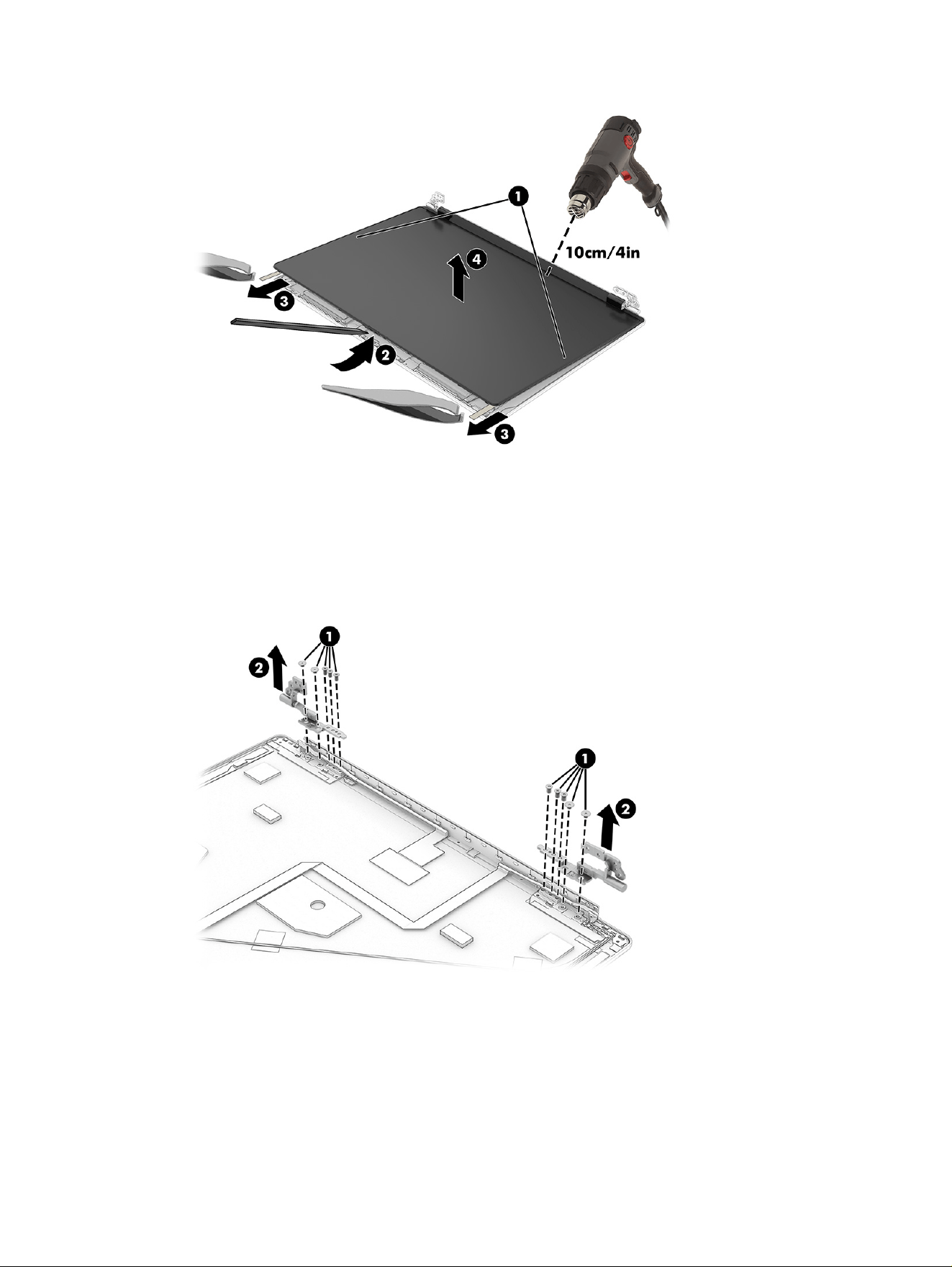
9. To remove the hinges from the display enclosure:
a. Remove the ve Phillips broadhead M2.0 × 2.0 screws (1) from each hinge.
b. Remove the hinges (2) from the display.
A hinge kit is available as spare part number P83633-001.
10. To remove the camera module:
Display assembly
59
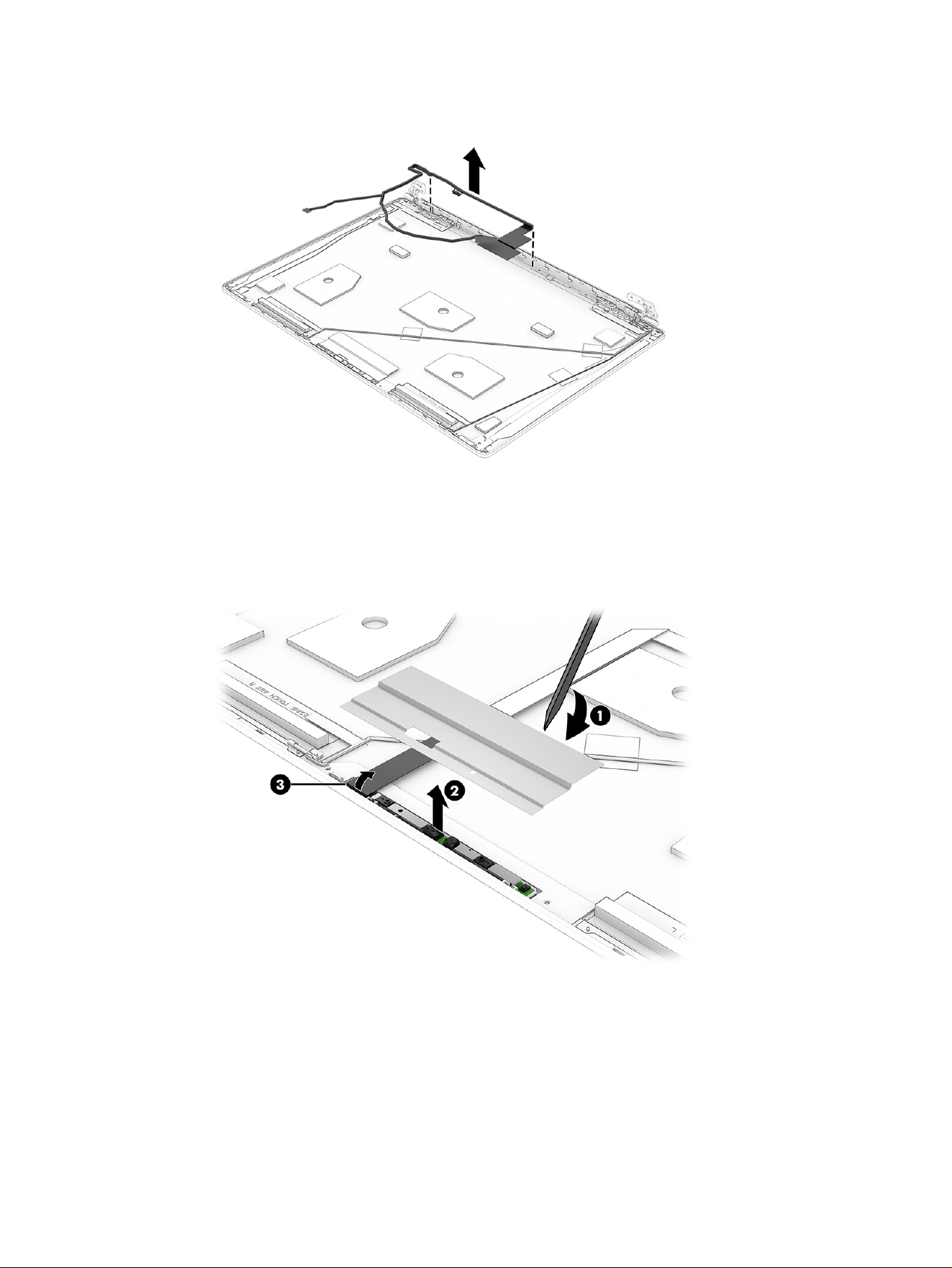
■
Remove the camera cable from the back cover.
a. Using a at tool (1), pry up the adhesive foil.
b. Lift up evenly across the module (2) and peel the module up from the display back cover, then
disconnect the cable from the reverse ZIF connector (3) on the module. The camera module is
available with the cable and rubber spacer in a kit as spare part number P83632-001.
11. To remove the display/camera cable, disconnect the cable (1) from the camera module, peel the
cable (2) off the inside of the display back cover, and then remove the cable.
60
Chapter 6 Removal and replacement procedures for authorized service provider parts
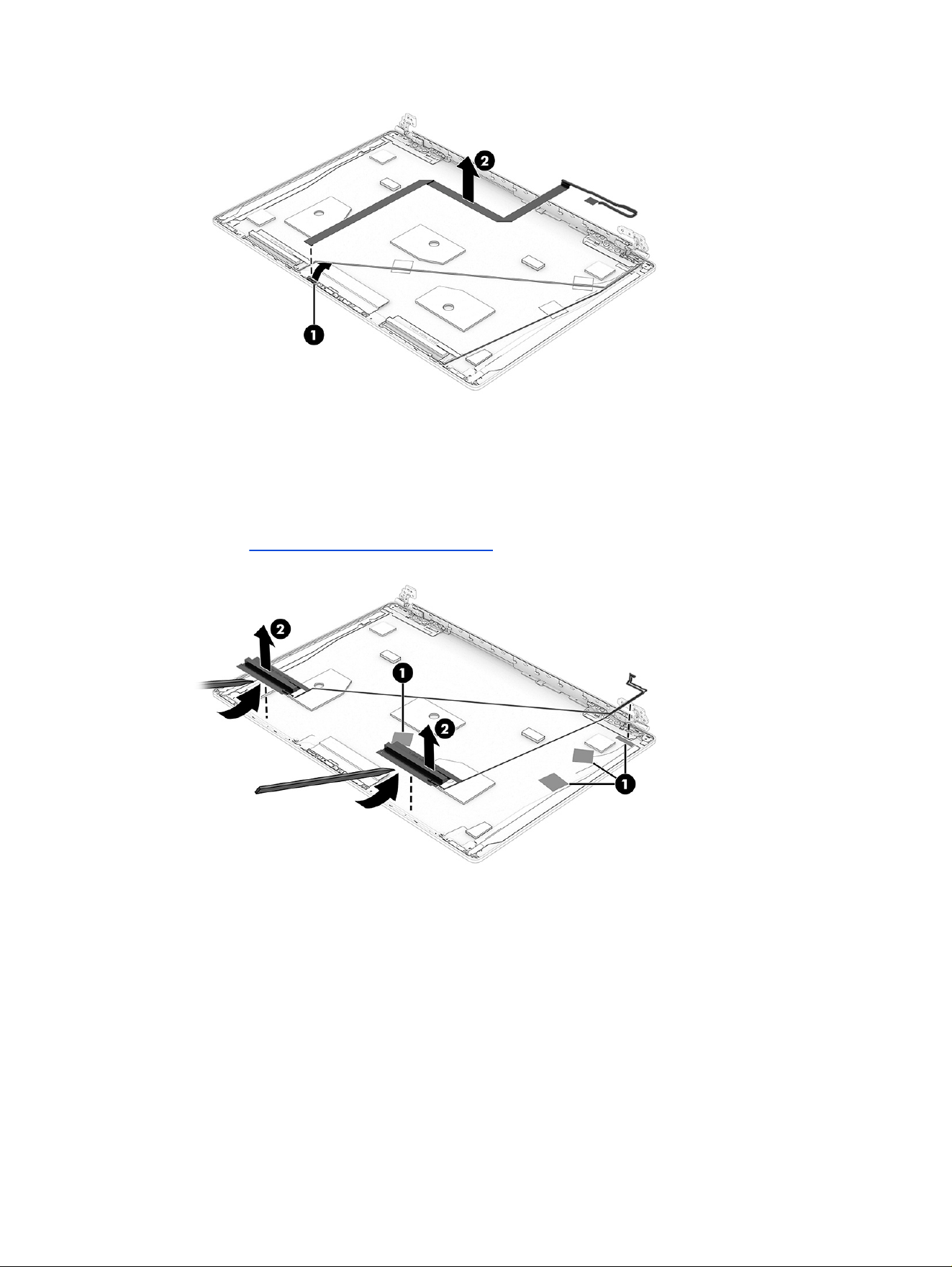
12. To remove the antenna cables, rst remove the cables from the tape (1) on the cover, then use a at
tool to pry up and remove the antenna modules (2) off the inside of the display back cover.
Antenna cables are available as part of the cable kit (with antenna) as spare part number
P83619-001.
See the Illustrated parts catalog on page 15 for part numbers for the display back covers.
13. To remove the touch control board, peel the black tape (1) off the board and remove it, then
disconnect the touch control cable from the touch control board (2).
a. Disconnect the cables from the touch control board ZIF connectors (3).
b. Use a at tool to pry up the touch control board (4) and then lift the board away from the back
cover (5).
The touch control board is available as spare part number P84442-001 (for AMD processors)
and P83635-001 (for Intel processors).
Display assembly
61
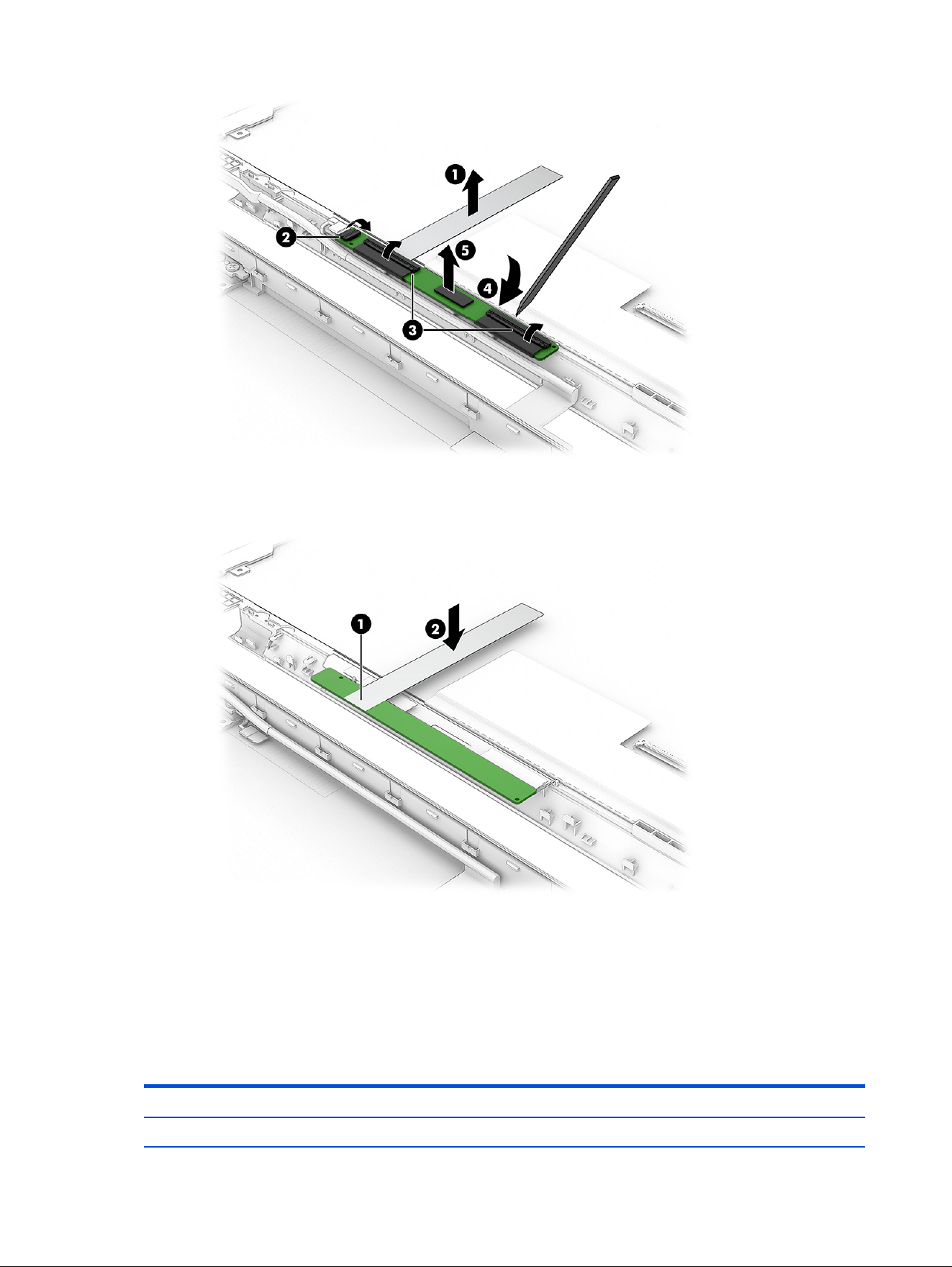
c. To install a new touch control board, rst afx the replacement tape to the control board in the
marked section (1) and then afx the tape to the back cover (2).
Reverse this procedure to reassemble and replace the display assembly.
Keyboard with top cover
The top cover with keyboard remains after removing all other spare parts from the computer. In this
section, the rst table provides the main spare part numbers for the top cover with keyboards. The second
table provides the country codes.
Table 6-11
Keyboard with top cover descriptions and part numbers
Description Spare part number
Keyboard with top cover (glacier silver) P83599-001
62 Chapter 6 Removal and replacement procedures for authorized service provider parts

Table 6-11 Keyboard with top cover descriptions and part numbers (continued)
Description Spare part number
Keyboard with top cover (meteor silver) P83600-001
Keyboard with top cover (silk sand) P83601-001
Keyboard with top cover (starlit blue) P83602-001
NOTE: Not all colors are available in all countries.
Table 6-12 Spare part country codes
For use in country or
region
Spare part
number
For use in country or
region
Spare part
number
For use in country or
region
Spare part
number
Belgium -A41 Hungary -211 South Korea -AD1
Bulgaria -261 Israel -BB1 Spain -071
Chile -161 Italy -061 Switzerland -BG1
Czech Republic/Slovakia -FL1 Japan -291 Taiwan -AB1
Denmark, Finland, and
Norway
-DH1 The Netherlands -B31 Thailand -281
French Canada -DB1 Portugal -131 Turkey -141
France -051 Russia -251 Ukraine -BD1
Germany -041 Saudi Arabia -171 United Kingdom -031
Greece -151 Slovenia -BA1 United States -001
Keyboard with top cover 63

Troubleshooting guide7
This chapter primarily focuses on troubleshooting HP Mobile Workstations. The information is provided so
that you can solve problems yourself or at least narrow down the number of possible causes.
Based on some of the most common symptoms, this chapter identies logical steps and available
resources or tools for resolving an issue. HP recommends that you follow the instructions carefully,
observe safety precautions, and note any observations or results. Capturing this information can help
identify and resolve the problem more quickly.
WARNING! To reduce the risk of electric shock or damage to the equipment:
● Do not disable the power cord grounding plug. The grounding plug is an important safety feature.
● Plug the power cord into a grounded (earthed) outlet that is easily accessible at all times.
● Disconnect power from the equipment by unplugging the power cord from the AC outlet.
● Before disassembling notebooks, always disconnect power and remove the battery.
IMPORTANT: Static electricity can damage the electronic components of the computer. To prevent
damage to the computer, carefully observe the electrostatic discharge precautions.
● Discharge static electricity by briey touching a grounded metal object before you begin.
● Work on a static-free mat.
● Wear a static strap to ensure that any accumulated electrostatic charge is discharged from your
body to the ground.
● Create a common ground for the equipment that you are working on by connecting the static-free
mat, static strap, and peripheral units to that piece of equipment.
● For more information, see Electrostatic discharge information on page 23.
IMPORTANT: The computer includes customer self-repair parts and parts that should be accessed
only by an authorized service provider. Accessing parts described in Removal and replacement
procedures for authorized service provider parts on page 41 can damage the computer or void the
computer warranty.
Resources
Use this table to locate troubleshooting resources.
64
Chapter 7 Troubleshooting guide
Table 7-1 Troubleshooting resources and their descriptions
HP Resource Tool Description Link
HP Customer Support Provides important support, such as warranty,
support cases, drivers, Customer Advisories,
Customer and Security Bulletins, and Product
Change Notices.
https://support.hp.com/us-en/contact-hp
Support Alerts Allows you to sign up for HP product updates. https://support.hpe.com/hpesc/public/
docDisplay?docId=c01139159
HP Support Forums Provide discussions about HP products and issues. http://h30434.www3.hp.com/psg/
Vendors’ websites Provide additional information for associated
components such as Intel (processor, WLAN),
Microsoft (Windows), AMD/NVIDIA® (GPU), and so
on.
http://www.intel.com/
content/www/us/en/homepage.html
http://www.amd.com
http://www.nvidia.com
General troubleshooting steps
This section helps you become familiar with troubleshooting methodology and
efciently resolve
problems.
Proceed through the steps in the following table until the issue is resolved, and then move on to the next
step that is relevant to the issue. For example, if you resolve a memory issue using the HP PC Diagnostics,
or Unied Extensible Firmware Interface (UEFI), tool in step 6, you can then move on to step 10 to reseat the
memory into its memory slot.
NOTE: You can ignore troubleshooting steps that do not apply to your issue.
Table 7-2
Troubleshooting methodology and general troubleshooting steps
Identify issue Analyze issue Resolve issue Verify solution
1. Understand the issue
on page 66
2. Examine the
environment on page 68
3. Perform a visual
inspection of hardware on
page 68
4. Update BIOS and
drivers on page 69
5. Remove or uninstall
recently added hardware,
software on page 69
6. HP Hardware Diagnostics
and Tools on page 70
7. Status lights, blinking light
codes, troubleshooting lights,
and POST error messages on
page 72
8. Hard reset on page 75
9. Soft reset (Default Settings) on
page 76
10. Reseat cables and connections
on page 76
11. Test with minimum conguration
on page 77
12. Test with veried working
conguration (hardware or operating
system) on page 78
13. Replace the system board on
page 78
Verify solution
on
page 79
Identify the issue
Use these guidelines to correctly determine the problem.
General troubleshooting steps
65

1. Understand the issue
It is important to understand the issue that occurred, including related symptoms. It helps to understand
the basic computer startup sequence as well as the failure itself.
Startup sequence
The computer performs several steps after you press the power button or restart the computer.
It is important to understand where in the startup sequence the symptoms occur. The following table lists
the phases of the startup sequence and explains the symptoms that might occur in each phase. For
example, a blue screen error (BSOD) often occurs during the performance phase.
Table 7-3 Startup sequence and associated failures
Item Procedure
Startup After you press the power button, the computer starts after all internal power rails (such as 5 V, 3.3 V) are
stable.
Conrm that power lights are on and fan is spinning.
Common issues: all lights are off; troubleshooting lights are on; computer does not start; video is absent.
POST (UEFI/BIOS) Power-On Self-Test (POST) veries that hardware components (such as processor, hard drive, memory) are
functional. When POST is complete, the HP logo appears briey and then disappears.
If there are errors, the computer might exhibit blinking lights, POST error messages, or similar notications.
Common issues: lights blink; error message appears; system hangs (locks up or freezes)
Performance
(operating system)
System boots to operating system, and Windows logo screen appears.
Common issues: hangs, blue screen, distorted video, driver conict, slow performance, display issue (dead
pixel), I/O issue (no speaker sound), wireless/audio unavailable, noise.
See Analyze the issue on page 69 table for detailed troubleshooting information.
Failure classication
Failure classication is a breakdown of different types of failures and symptoms that could occur during
the boot-up sequence.
Table 7-4 Failure classication by startup sequence on page 67 and Table 7-5 Failure classication by
hardware devices on page 68 represent the failure classication for common notebook failures.
Table 7-4 Failure classication by startup sequence on page 67 categorizes failures by the startup
sequence.
1. Power-on: Common issues are no power, recycle, or restart.
2. POST: Common issues are no boot (despite power), light ash, or diagnostics error.
3. Performance: Common issues are Intermittent Loss of Power, Blue Screen, Hang. In many cases,
issues can be identied and associated with particular hardware (for example, display or storage).
Table 7-5 Failure classication by hardware devices on page 68 categorizes failures by hardware:
● Display
● I/O (input/output) devices
66
Chapter 7 Troubleshooting guide
● Storage
● Mechanical
A single symptom can be listed under different groups. For example, No Video can belong to (1) power-on
or (4) display; but ickering when turned on should be listed in (4) display. Or, in another example, a blue
screen can be caused by a driver conict in performance (3), but it can also be caused by a defective hard
drive under (6) storage. Therefore, failures that share similar symptoms are noted.
If possible, make a record of the failure symptom, the phase of the startup sequence where the failure
occurs, and the most likely location in the failure tree (Table 7-4 Failure classication by startup sequence
on page 67 and Table 7-5 Failure classication by hardware devices on page 68). This record helps
isolate the issue and indicate the next steps. For example, when the computer is running the operating
system, it can experience an issue with (4) display, (5) I/O devices (keyboard, wireless, and so on), (6)
storage, or (7) mechanical components (stuck buttons, thermal shutdown, and so on).
NOTE: Uncategorized is used if an issue found is not listed. For example, Bluetooth is offered on certain
hardware congurations; therefore, you can classify a Bluetooth issue under I/O Device if needed.
Failure classication by startup sequence
Use this table to locate failure classication information.
Table 7-4 Failure classication by startup sequence
1. Power-on 2. POST 3. Performance
1. No power on page 81
2. Intermittent power-on, shutdown,
reboot on page 83
a
3. AC adapter issue on page 84
4. Battery not recognized, not
charging on page 85
5. Battery discharges too fast on page
88
6. Burnt smell on page 88
1. No video (with power) on page
89
2. Blinking lights on page 90
3. Diagnostics error messages on
page 91
4. BIOS password on page 91
1. Intermittent shutdown on page 92
a
2. Blue screen on page 93
b
3. Freeze at Windows Logo (hang/lockup)
on page 95
4. Electromagnetic Interference (EMI) on
page 96
5. No wake up on page 97
6. Unresponsive on page 98
7. Slow performance on page 99
c
8. HP Smart Adapter warning message
on page 99
9. Incorrect time and date on page 100
a,b,c
similar symptoms
Failure classication by hardware devices
To determine failure by device, use this table.
Failure
classication by startup sequence 67

Table 7-5 Failure classication by hardware devices
4. Display 5. I/O devices 6. Storage 7. Mechanical
1. Display anomalies on
page 101
2. Dead pixel on page 103
3. No video (internal) on
page 103
c
4. No video (external) on
page 104
c
5. DisplayPort/VGA on
page 104
6. HDMI on page 104
7. No or bad external video
via docking on page 105
8. Incorrect or missing
color/distorted image on
page 106
9. Touch screen on page
107
1.
Keyboard on page 108
2. Keyboard point stick on
page 109
3. Keyboard backlight on
page 110
4. Touchpad on page 110
5. Network Connectivity
Ethernet (RJ-45 jack) on
page 111
6. Network connectivity
wireless (WLAN) on page
111
7. WWAN on page 112
8. USB on page 112
9. Smart card reader on
page 113
10. Speaker, headphone -
audio issues on page
114
11. Thunderbolt (TB) on page
116
1.
Hard drive or solid-state
drive not recognized on
page 117
2. No boot to operating
system (no read/write
error) on page 118
3. Read-write error on page
119
4. Slow performance on
page 119
b
5. Blue screen (BSOD) error
on page 120
a
6. Noisy hard drive on page
120
1.
Noise (sound) on page
121
2. Fan runs constantly on
page 122
3. Thermal Shutdown on
page 123
a,b,c
similar symptoms
2. Examine the environment
It is important to examine the computer’s environment. If you can quickly identify the cause of the issue,
fewer resolution steps might be needed.
Perform the following environment inspections:
● Check all cables and connections to be sure that no connections are loose.
● Conrm that power sources are good, such as AC outlet or adapter (110 V/220 V AC), power strip.
Test with a veried working AC outlet.
● Check for compatibility issues between the computer and third-party devices, peripherals, uncertied
devices, incompatible hardware (for instance, macOS device). Incompatibility can result in blue screen
errors, improper operation, and so on.
● Isolate the computer from sources of electromagnetic interference (EMI), such as cell phones, two-
way radios, oor mats, fans (and other electronic motors). EMI might contribute to a display freeze
issue or lockup.
3. Perform a visual inspection of hardware
Perform a physical inspection of the computer.
68
Chapter 7 Troubleshooting guide

● Look for abnormalities such as a cracked display, dented battery, broken latches for battery bay,
keyboard key caps popped out, dust over connectors, liquid spill over keyboard.
● Look for signs of drop, movement, or vibration that might cause internal and external loose
connections.
4. Update BIOS and drivers
Whenever possible, update to the latest BIOS, rmware, and drivers before troubleshooting.
IMPORTANT: Note that some customer company policies prohibit updates. Check your company
policy before taking action.
The updates might include xes for your computer issues, and they might also enhance system
performance. HP continually improves the update process to make it easier. You can update the BIOS
locally through a manual process, through an automatic installation, or through a remote installation on
multiple units.
Manually updating BIOS and drivers
Use this information to update the BIOS.
● To manually update the BIOS and drivers, see the Setup Utility (BIOS) chapter.
● See the specic BIOS update installation instructions that accompany the download.
Remotely deploying the BIOS and drivers
Instead of manually searching for and downloading each SoftPaq, users and IT personnel can use two
tools to identify and download all appropriate SoftPaqs for the selected HP models.
● HP SoftPaq Download Manager (SDM) is a software tool that streamlines the download, extraction,
and installation process of SoftPaqs, including BIOS and drivers.
● HP System Software Manager (SSM) is a software tool that simplies the deployment of SoftPaqs to
HP computers.
Analyze the issue
Use these steps to evaluate and interpret the problem.
5. Remove or uninstall recently added hardware, software
HP has designed this computer and validated it using a full-range hardware and software qualication
matrix. If an issue appears to have started recently, it might be related to the recent addition of hardware
or software.
A good method to determine the root cause is to remove recently added components or uninstall
applications one at a time and restart the computer when necessary.
IMPORTANT: After you have completed the process of uninstalling hardware or software and are
ready to reinstall, be sure that the new device is seated properly and all cables are correctly connected.
After installing the device, restart the computer, and be sure that the new device is turned on. In addition,
if the new device is a root cause of a problem, it could cause a conict in drivers or incompatibility issues
with other installed programs. For any new hardware you have added, be sure to install the latest drivers
available from the device vendor website.
4. Update BIOS and drivers
69

6. HP Hardware Diagnostics and Tools
HP offers diagnostics and tools to diagnose hardware failure. This section describes how to use some of
these tools. Check for the latest versions before use.
HP PC Hardware Diagnostics UEFI
HP PC Hardware Diagnostics is a Unied Extensible Firmware Interface (UEFI) that allows you to run
diagnostic tests to determine whether the computer hardware is functioning properly.
The HP PC Hardware Diagnostics UEFI tool is built within BIOS (basic memory and hard drive diagnostics
only), or within new hard drives themselves. These drives contain more advanced versions of the
diagnostic tool than the BIOS-based version.
In addition, for HP authorized service partners and IT professionals who need to support a
mixed environment of older and newer HP/Compaq PCs, the HP PC Hardware Diagnostics Tool
(https://support.hp.com/us-en/help/hp-pc-hardware-diagnostics) supports a wide range of HP computers.
The tool runs outside the operating system so that it can isolate hardware failures from software issues,
whether caused by the operating system or applications. In reality, you can determine many problems
using this tool if the issue is a defective part or a loose connection.
The tool has three major functions:
● System Tests check the computer’s hardware to verify that everything is functioning properly. If your
system won’t boot into Windows, try the Quick System Test. For more comprehensive testing, use the
Extensive System Test option. If the System Test did not detect a hardware problem, continue with the
Component Tests.
● Component Tests focus on selected hardware components in your computer.
● Firmware Management updates your computer’s BIOS to the latest version (available separately) or
rolls back to a previous version.
1. Turn on or restart the computer, quickly press the esc key on the computer, and then press f2.
The BIOS searches three places for the diagnostic tools, in the following order:
a. Connected USB drive
b. Hard drive
c. BIOS
2. When the diagnostic tool opens, use the keyboard arrow keys to select the type of diagnostic test you
want to run, and then follow the on-screen instructions.
Screen capture appearance might vary.
70
Chapter 7 Troubleshooting guide
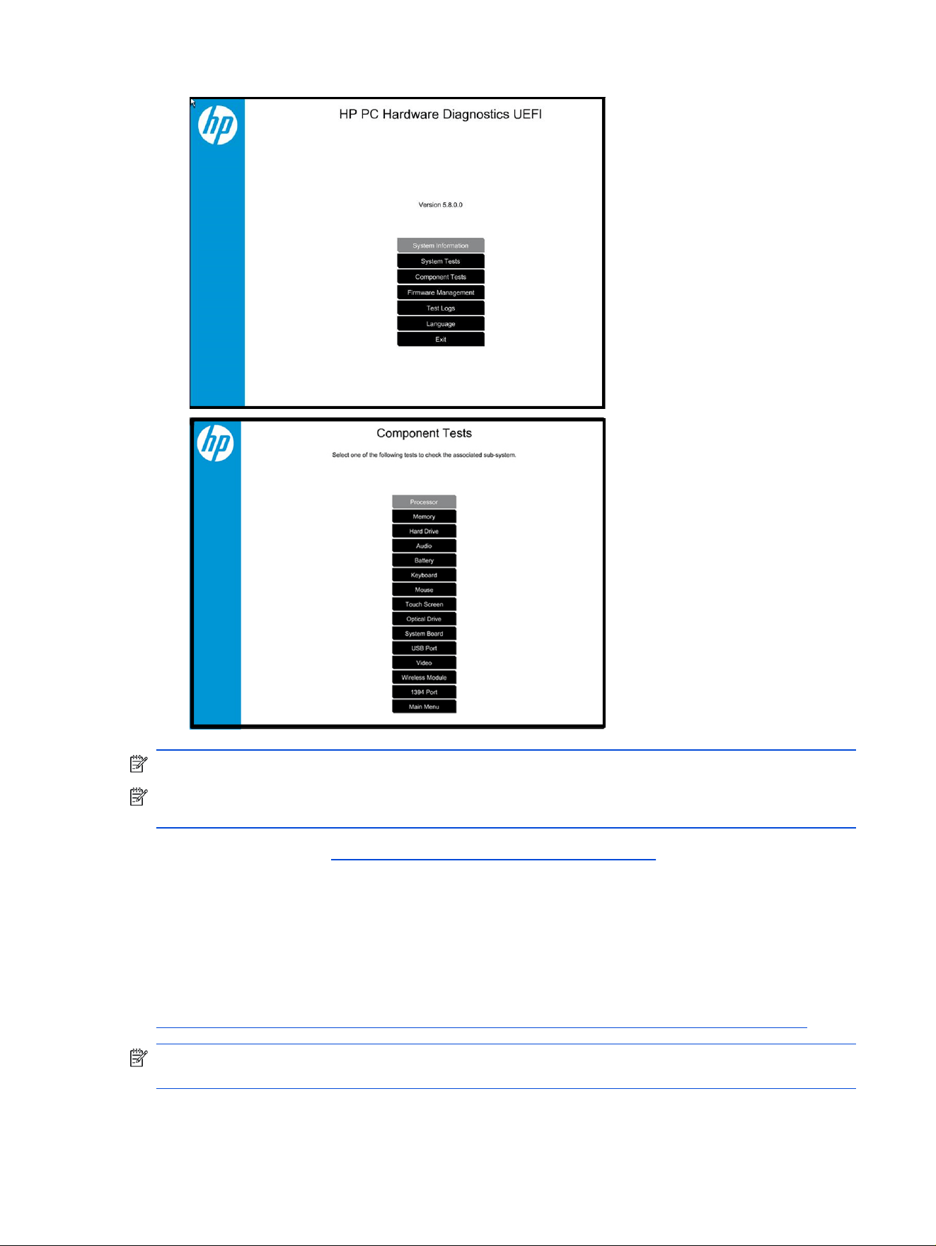
NOTE: Using this tool can be especially helpful when the computer cannot boot to Windows.
NOTE: If a component fails a test, write down the information so that it is available when you contact
support. The information is also available in Test Logs on the Main Menu.
For more information, see Using HP PC Hardware Diagnostics on page 152.
HP BIOS Conguration Utility (BCU)
HP BCU is a free utility that captures the BIOS settings and their values. This tool provides a text le of the
computer’s BIOS conguration. This le can help identify any settings that are contributing to an issue.
In some cases, it might help to compare this BIOS text le to the default settings of the computer.
For more information, see
http://ftp.hp.com/pub/caps-softpaq/cmit/whitepapers/BIOS_Conguration_Utility_User_Guide.pdf.
NOTE: HP recommends that you reset BIOS before trying BCU. Resetting the BIOS is always available
and relatively quick to try, whereas BCU takes extra time and effort.
HP BIOS
Conguration Utility (BCU) 71

HP Image Diagnostic Tool
Available to HP Authorized Support Partners (ASPs) and users, this tool collects information about the
current state of the computer, including product serial number, platform and BIOS information, and
information about user-installed software and hardware components.
Access this tool at https://ftp.hp.com/pub/caps-softpaq/cmit/support/HP_ImageDiags.html. HP
encourages you to review the report before sending it to support. The report can assist you with
diagnostics and solutions to problems you encounter.
HP Thermal Monitor
You can use HP Thermal Monitor to stress the processor and GPU and monitor the temperature values of
various components in the system.
NOTE: Available only to authorized service providers and technicians.
The components that are currently monitored include the processor, GPU, ACPI thermal zones, hard drive,
and battery. The tool reads the temperatures of the components, logs the data, and helps to determine
whether the computer would overheat in the event of thermal shutdown, fan spinning loud, and so on.
Non-HP diagnostics tools
Refer to the following diagnostic tools for troubleshooting help.
Windows-To-Go USB
Windows-To-Go USB is a Microsoft-based tool for Enterprise editions of Windows that can help in
troubleshooting. You can nd a process online about how to create a live Windows USB drive.
Intel Processor Diagnostic Tool
Determine what processor is in your computer and verify the processor operating frequency. The tool also
tests specic processor features and performs a stress test on the processor. For more information, see
http://www.intel.com/support/processors/sb/CS-031726.htm?iid=subhdr+tools_procdiagtool.
7. Status lights, blinking light codes, troubleshooting lights, and POST error messages
Carefully observe any behavior that the computer is exhibiting: status lights, blinking lights, and POST error
messages during boot. It is important to understand what these indicators mean.
Status lights
The following table describes basic lights on the computer.
72
Chapter 7 Troubleshooting guide

Table 7-6 Power button functions and lights and their descriptions
Component Description
Power button When the computer is off, press the button to turn on the computer.
When the computer is on, press the button briey to initiate sleep (Windows) or suspend
(Linux®).
When the computer is in the sleep state, press the button briey to exit sleep (Windows) or
suspend (Linux).
When the computer is in hibernation, press the button briey to exit hibernation.
IMPORTANT: Pressing and holding down the power button results in the loss of unsaved
information.
If the computer stops responding and operating system shutdown procedures are
ineffective, press and hold the power button.
Front power light
On: The computer is on.
Blinking: The computer is in the sleep state.
Off: The computer is off.
Front AC adapter and battery light White: The computer is connected to external power, and the battery is charged from 90%
to 99%.
Amber: The computer is connected to external power, and the battery is charged from 0%
to 90%.
Blinking amber: A battery that is the only available power source has reached a low
battery level. When the battery reaches a critical battery level, the battery light blinks
rapidly. By default, the critical battery level is dened in Power Options as 5%.
Off: The battery is fully charged.
Front hard drive light Blinking white: The hard drive is being accessed.
Amber: HP 3D DriveGuard has temporarily parked the hard drive.
Rear AC adapter light White: The computer is connected to external power.
Off: The computer is not connected to external power.
Blinking light codes
During startup, the computer might not start properly. If this occurs, blinking light codes can help identify
the cause.
The computer uses the following blinking lights to identify a hardware component that reports an error
during startup. For more information, see Blinking lights and boot error codes on page 124.
Table 7-7
Blinking light codes and what they mean
Blink codes Error
Amber battery light: blinks 1 Hz continuously Embedded controller unable to load rmware
Caps and num lock lights = 1 blink Processor not executing code
Caps and num lock lights = 2 blinks BIOS recovery code unable to nd valid BIOS recovery image
Caps and num lock lights = 3 blinks Memory module error
Caps and num lock lights = 4 blinks Graphics controller error
Blinking light codes 73

Table 7-7 Blinking light codes and what they mean (continued)
Blink codes Error
Caps and num lock lights = 5 blinks System board error
Caps and num lock lights = 6 blinks Intel Trusted Execution Technology (TXT) Error
Caps and num lock lights = 7 blinks Sure Start unable to nd valid BIOS Boot Block image
Caps and num lock lights = 8 blinks Sure Start has identied a problem (Manual Recovery Policy Set)
POST error messages
The Power-On Self-Test (POST) is a series of diagnostic tests that runs automatically when the computer
is turned on. If the POST encounters a problem, visual error messages are displayed before the operating
system starts.
POST checks the following items to ensure that the computer system is functioning properly:
● Memory
● Processors
● BIOS
● Mass storage devices
● Fans
The following table describes errors encountered during HP PC Hardware Diagnostics UEFI.
Table 7-8
System diagnostics failure codes and actions to address the failure
Test description Failure description Error
code
Suggested user actions
Startup Test Memory module 200 Attempt to reseat the memory module, and then repeat the
test.
For details on troubleshooting issues related to the
memory module, search for support documentation at
http://www.hp.com/support.
Startup Test Hard Disk 1 SMART 301 Attempt to reseat the hard drive, and repeat the test. The hard
drive might have failed.
Boot Device Manager Boot device not found 3F0 Reset BIOS. Then reseat the hard drive, and repeat the test.
BIOS Recovery BIOS Recovery Occurred 500 This message indicates that BIOS recovery was completed
successfully. No further action is required.
BIOS Application BIOS Application Error 501 The BIOS installation might have become corrupted. Download
the latest version of the BIOS and install it.
If reinstalling the BIOS fails, contact support for further
assistance.
CMOS Recovery CMOS Recovery
Occurred
502 This message indicates that CMOS recovery was completed
successfully. No further action is required.
74 Chapter 7 Troubleshooting guide

Table 7-8 System diagnostics failure codes and actions to address the failure (continued)
Test description Failure description Error
code
Suggested user actions
Battery Check Primary Battery Replace 601 This message indicates that the primary battery has
very low capacity. Search for support documentation at
http://www.hp.com/support for details on using the HP Support
Assistant to verify the battery capacity and, if necessary, order
a replacement.
Wireless Modules Not installed or not
responding
701 Reseat the wireless LAN adapter module and antennas.
Because seating or reseating a wireless LAN adapter is unique
to each computer model, see the WLAN module removal
section in the removal and replacement chapter for further
details.
Contact support if third-party wireless adapters are installed in
the computer.
Fan Fan not operating
correctly
90B The system fan might be malfunctioning. Replace the fan.
Resolve the issue
The following sections help you x the issue.
8. Hard reset
A hard reset (or forced reset) erases all information in the computer’s memory and might restore
functionality. Resetting the computer forces the system to clear and reestablish the connections between
the BIOS and the hardware.
Performing a hard reset might x the following common conditions:
● Windows stops responding.
● Computer stops before Windows loads, indicated by incomplete startup, blinking cursor on a black
background, and errors relating to operating system not found or a missing drive.
● Display suddenly goes blank and stays blank.
● Software freezes.
● Keyboard stops responding.
● The computer does not exit sleep or suspend state.
● An external device stops responding. Turn off the power to that device in addition to performing the
steps in this document.
Before performing a hard reset, you must disconnect or remove all peripheral devices. Start and test the
computer by itself, and if the problem is not resolved, reconnect one peripheral device at a time. To resolve
the startup or operational problem, run HP Support Assistant, or manually install all updated drivers from
Microsoft and HP.
Before beginning, turn the computer over and look for a battery compartment door or service door. On
some platforms, the battery is considered removable but not accessible.
1. Turn off the computer.
Resolve the issue
75
2. Remove the computer from any port replicator or docking station.
3. Disconnect all external connected peripheral devices such as USB storage devices, external
displays, and printers.
4. Unplug the AC adapter from the computer.
5. Disconnect the battery.
6. Press the power button + Windows logo + V.
7. Reconnect the battery and plug the AC adapter back into the computer, but do not connect any of the
peripheral devices.
8. Press the power button to turn on the computer.
9. If a startup menu appears, use the arrow keys to select Start Windows Normally, and then press the
enter key.
10. After reconnecting each of the peripheral devices, run Windows Update and HP Support Assistant to
update all device drivers.
CMOS refers to the battery-powered semiconductor chip located on computer’s system board. Notebooks
store low-level settings like the system time and hardware settings in CMOS. Sometimes you must clear
CMOS, which requires disconnecting the AC adapter and battery.
NOTE: Clearing the CMOS should only be performed for troubleshooting purposes. There is no reason
to clear CMOS if the computer is working properly.
9. Soft reset (Default Settings)
If your computer has issues starting up, has errors during startup, has issues after you add hardware, or
has other abnormal system behaviors that you cannot resolve through any other methods (for example,
hard reset), it might be necessary to reset the system BIOS to default settings.
NOTE: Some company policies prohibit updates or changes. Check whether the computer has custom
BIOS settings before taking action.
To load BIOS to default settings: Restart the computer, and then press f10 > Main > Restore defaults.
For more information, see http://support.hp.com, and then search for BIOS Setup Utility Information and
Menu Options.
10. Reseat cables and connections
Many problems are caused by improper connections or loose connections because of abnormal
movement and vibration.
NOTE: Before disassembling the computer to reseat cables and connections, always disconnect
power and remove the battery, or disconnect a nonremovable battery.
See Cable management on page 135 and Connector types on page 136 for suggested cable
management practices when you remove and install components.
You can access and reseat connections for Customer Self-Repair (CSR) parts. Examples of reseating
hardware include:
● Reseating the battery into the battery bay can resolve no-battery found and no-charging issues.
76
Chapter 7 Troubleshooting guide

● Reseating memory modules can resolve memory error, startup, and blue screen issues.
● Reseating the hard drive can resolve a POST error 3F0 (no boot device) issue (see POST error
messages and user actions on page 127).
● Reseating the keyboard cable can resolve an unrecognized keys error.
● Reseating the wireless module and antenna cable can resolve a wireless connection issue.
For eld replaceable units (FRUs), authorized service providers can try the following steps. For more
information, see Removal and replacement procedures for authorized service provider parts on page 41.
● Reseating the fan cable can x POST error 90B (no fan detected) issue (see POST error messages
and user actions on page 127).
● Reseating the power cable can x a startup issue.
● Reseating the daughterboards can resolve their functional issues. Some models might have other
items such as a power button board or VGA board.
● Reseating graphics cables and panel connectors can x distorted or ickering video.
● Replacing thermal pads might resolve thermal power-down issue.
11. Test with minimum
conguration
The factory-shipped computer (hardware conguration and preinstalled operating system image) is well
tested and ready for use. Therefore, using the original factory hardware conguration or booting to
operating system safe mode often resolves issues quickly.
● Disconnect any external USB storage, remove any discs in optical drives, remove the computer from a
docking station, remove external video, and others.
● In addition to removing recently added components, you can narrow the issue down further with a
minimum conguration. For example, if HP PC Diagnostics reports a memory error, test one memory
module at a time to isolate the defective module.
● If the computer does not successfully boot the operating system, booting to safe mode might help
identify the following possible causes of the issue.
Essential hardware conguration
If none of the previous steps resolve the issue, start the computer with essential hardware only. The
purpose is to remove as much as hardware as possible while still maintaining the computer’s ability to turn
on.
NOTE: This step is to be used by authorized service providers only. HP will not honor the warranty for a
system tested with the system board removed without the heat sink or fan.
This essential conguration is often used to troubleshoot power-on related issues, such as no-boot,
reboot, and freezing issues.
The essential hardware consists of the following components:
● System board
● AC adapter (unplug nonremovable battery or remove battery)
● Processor and heat sink or fan
11. Test with minimum
conguration 77

The processor might be integrated into the system board.
● Memory (one veried working memory DIMM)
● Graphics card, if no VGA port is available on the system board
Platform might have both Intel integrated graphics and discrete graphics. Therefore, you might not
need a discrete graphics card.
● External VGA monitor
● External USB keyboard
● External mouse
NOTE: After you remove the service door, disconnect all connections (internal keyboard, display,
discrete GPU, hard drive or SSD, daughterboards, and so on) to achieve the essential hardware
conguration. Do not disassemble the system board from its enclosure at this time.
Reverse the previous procedure by reinstalling each piece of hardware removed, one piece at a
time, and testing your computer after each installation. Because your computer works with only the
essential hardware installed, those parts must be working properly. This means that one of the hardware
components removed is causing the computer to fail. By installing each device back into the computer and
testing after each installation, you eventually identify the failing hardware.
Safe mode
A driver conict often results in a blue screen error message. Starting in safe mode can resolve many
issues in Windows because safe mode forces the computer to load a limited version of Windows which
contains only essential les.
Safe mode is useful for troubleshooting problems with programs and drivers that might not start correctly
or that might prevent Windows from starting correctly. If a problem does not reappear when you start in
safe mode, eliminate the default settings and basic device drivers as possible causes.
12. Test with
veried working conguration (hardware or operating system)
One troubleshooting technique that can quickly isolate an issue is using a veried working part while
testing. A good example is to use an external keyboard, mouse, or VGA monitor when you have issues with
an internal keyboard, touchpad, or display.
Testing with a veried working AC adapter can identify an error caused by a faulty one. Similarly, testing
with a veried working operating system can determine bad behaviors of the current operating system.
NOTE: In some situations, more than one item might contribute to a problem.
13. Replace the system board
Only authorized service providers may replace the system board. This should not be considered an initial
step taken to resolve an issue.
Review and perform all steps discussed previously before replacing the system board. 4. Update BIOS and
drivers on page 69, 7. Status lights, blinking light codes, troubleshooting lights, and POST error messages
on page 72, 8. Hard reset on page 75, and 9. Soft reset (Default Settings) on page 76, or 10. Reseat
78
Chapter 7 Troubleshooting guide

cables and connections on page 76 can resolve many system board issues without requiring the effort of
replacing unnecessary hardware.
IMPORTANT: System board failure is not common. Do not replace the system board until you have tried
all other troubleshooting options.
NOTE: Determine whether a previous service case might be related to the current problem. For
example, a fan detection issue could be caused by a loose connection resulting from previous service.
NOTE: Most of the time, effective troubleshooting can prevent a system board replacement.
Situations that can prevent resolution of the issue:
● The information provided about the issue omits key details, including any actions taken before the
issue occurred.
● BIOS, software, and drivers have not been updated.
● Cables or connections are loose.
● Technician is unaware of information available from the HP Support website (CA - Customer
Advisory).
● The issue is related to existing or known issues that might be identied in existing support articles.
● Technician might have omitted steps in the provided repair instructions (for example, Spare Part
Replacement Instructions).
● Skipping one of the steps from the Troubleshooting Methodology table results in No Defect Found
(NDF)/No Fault Found (NFF)/No Issue Detected (NID) messages.
Verify solution
Conrm that the implemented solution works.
● Reboot the system or device, and try to complete the task that produced the issue.
● If a part has been replaced, verify other basic functions. For example, GPU replacement requires
keyboard removal. Therefore, it is good practice to verify all basic components to be sure that the
solution is complete.
● Explain to the customer why the issue occurred and what was done to resolve it. If the solution you
used was in an HP public document, provide the document information to the customer, letting them
know they can locate it on http://www.hp.com. Also, tell them that there are other solutions available
on the website. Advise the customer to check the website rst when they have an issue. It might save
them time calling in.
● Document the correct issue. Update the case with as many details as possible for other agents and
engineers to analyze and study for lessons learned.
Helpful Hints
After you become familiar with the troubleshooting steps, use the helpful hints before running diagnostics
and troubleshooting.
Verify solution
79

At startup
These steps provide simple, useful checks that you can perform when troubleshooting.
TIP: If you have installed an operating system other than the factory-installed operating system, go to
http://www.hp.com/go/quickspecs and verify that it is supported on your system.
1. Be sure that the computer is plugged into a working AC outlet.
2. Be sure that power is connected to the docking station if you use a dock.
3. Be sure that the AC adapter light is on.
4. Be sure that the AC adapter is connected when you update BIOS to avoid BIOS corruption.
5. Be sure that the computer is turned on, the rear power light is solid white (connected to an external
power source), and the front power light is solid white (normal operation).
6. Remove all optical and ash drives from your system before turning it on.
7. Be sure that the boot option is set to a working operating system drive.
8. Be sure that externally connected monitors are turned on and their power lights are on. Not all
monitors are equipped with lights to indicate their functionality.
9. Turn up the brightness and contrast controls of a display or external display device if the screen is
dim.
During operation
The following steps provide simple, useful checks that you can perform when troubleshooting.
1. To wake the computer:
a. Press the power button or any key on the keyboard.
b. If the system remains in the sleep (Windows), suspend (Linux), or hibernate state, shut down the
system by pressing and holding the power button for at least four seconds.
c. If the system does not shut down, unplug the power cord, wait a few seconds, and then plug it in
again. Press the power button again to restart the system.
2. Look for blinking lights on the computer. The blinking lights could be error codes that help diagnose the
problem.
3. Check all cables for loose or incorrect connections, such as external devices, power cords, or docking
stations.
4. After installing a non–Plug and Play expansion board or other option, recongure the computer. For
example, if you upgrade to an SSD, you might have to recongure the boot order.
5. Be sure that all required device drivers have been installed. For example, if you have connected a
printer, you must install a printer driver.
6. If there is a network connection issue, plug another computer with a different cable into the network
connection. There might be a problem with the network plug or cable.
7. If hardware has recently been installed, remove it and determine whether the computer functions
properly.
80
Chapter 7 Troubleshooting guide

8. If software has recently been installed, uninstall it and determine whether the computer functions
properly.
9. If the screen is blank, conrm the display choice by pressing Windows logo + p and set to screen
only. You can also plug an external monitor into a different video port on the computer, if one is
available, and close the computer lid.
10. Verify that the latest version of BIOS, drivers, and software are installed. A new release might support
new features or x the problem.
11. Press the caps lock or num lock key. If the caps lock or num lock light toggles on or off, the keyboard is
likely operating correctly.
12. Press the touchpad On/Off button light. If the light toggles on or off, the touchpad is likely operating
correctly.
Consulting with HP Service
If further HP support is required, the following information might be requested when you call. It might be
helpful to take notes.
● Technical support registration number (if applicable)
● Product serial number
● Product model name and number
● Product identication number
● Applicable error messages
● Add-on boards or hardware
● Third-party hardware or software
● Operating system type and revision level
● Description of symptom or failure
Common issues and possible solutions
This section contains common issues, symptoms, and a series of tables that describe possible solutions
to issues from Failure Classication tables. The following sections identify the issue with symptoms and
solutions to resolve an issue.
Power-on issues
Use the following sections to troubleshoot power issues.
No power
When a unit experiences no power, there are several contributing factors to consider. Be sure to consider
all symptoms related to this behavior when troubleshooting.
Consulting with HP Service
81

Table 7-9 Issues, possible causes, and xes
Items Procedures
Symptoms
● Computer does not start
● Display is black or blank
● No fan noise
● No hard drive spinning
● Lights do not glow
Possible causes
Failed power input to the computer (external power source, AC adapter, faulty
battery).
Bad connection to the computer (bad power button, power connector).
Defective parts (memory, hard drive, graphics) or failed system board.
Troubleshooting steps
Perform quick check
Remove all external devices, including docking station.
Verify external power source (2. Examine the environment on page 68).
Perform a hard reset (8. Hard reset on page 75).
Verify AC adapter
Verify the battery before verifying the AC adapter. However, you can verify the AC
adapter rst, before opening the service door for a battery check.
● Verify AC adapter is compatible with product. Verify that the part number is for
this computer if possible.
● Verify AC adapter and power cord are good (no physical damage, bent middle
ID pin).
● Verify AC adapter works on a veried working computer.
● Plug in AC adapter and power on computer without battery.
● Inspect power port on computer side for any damage, dust, or debris.
● Check power light (7. Status lights, blinking light codes, troubleshooting lights,
and POST error messages on page 72). Rear power light indicates external
power to the computer is good.
Verify battery condition and status
1. Check battery condition (overall result, cycle life, voltage) using HP PC
Hardware Diagnostics UEFI tool.
2. Verify that battery is installed properly in battery bay without a gap and that
latch locks are tight (for models with removable batteries).
3. Check battery status light (7. Status lights, blinking light codes,
troubleshooting lights, and POST error messages on page 72). Be sure that
battery is not fully discharged, preventing system from booting.
4. Determine whether the computer can turn on with battery only.
5. Remove service door and test with a veried working battery. If the computer
boots, inspect original battery before replacement.
6. Test battery with a veried working computer to verify that it works.
7. If the computer still does not boot, remove battery and boot on AC power only.
The following steps are for authorized providers or technicians.
82 Chapter 7 Troubleshooting guide
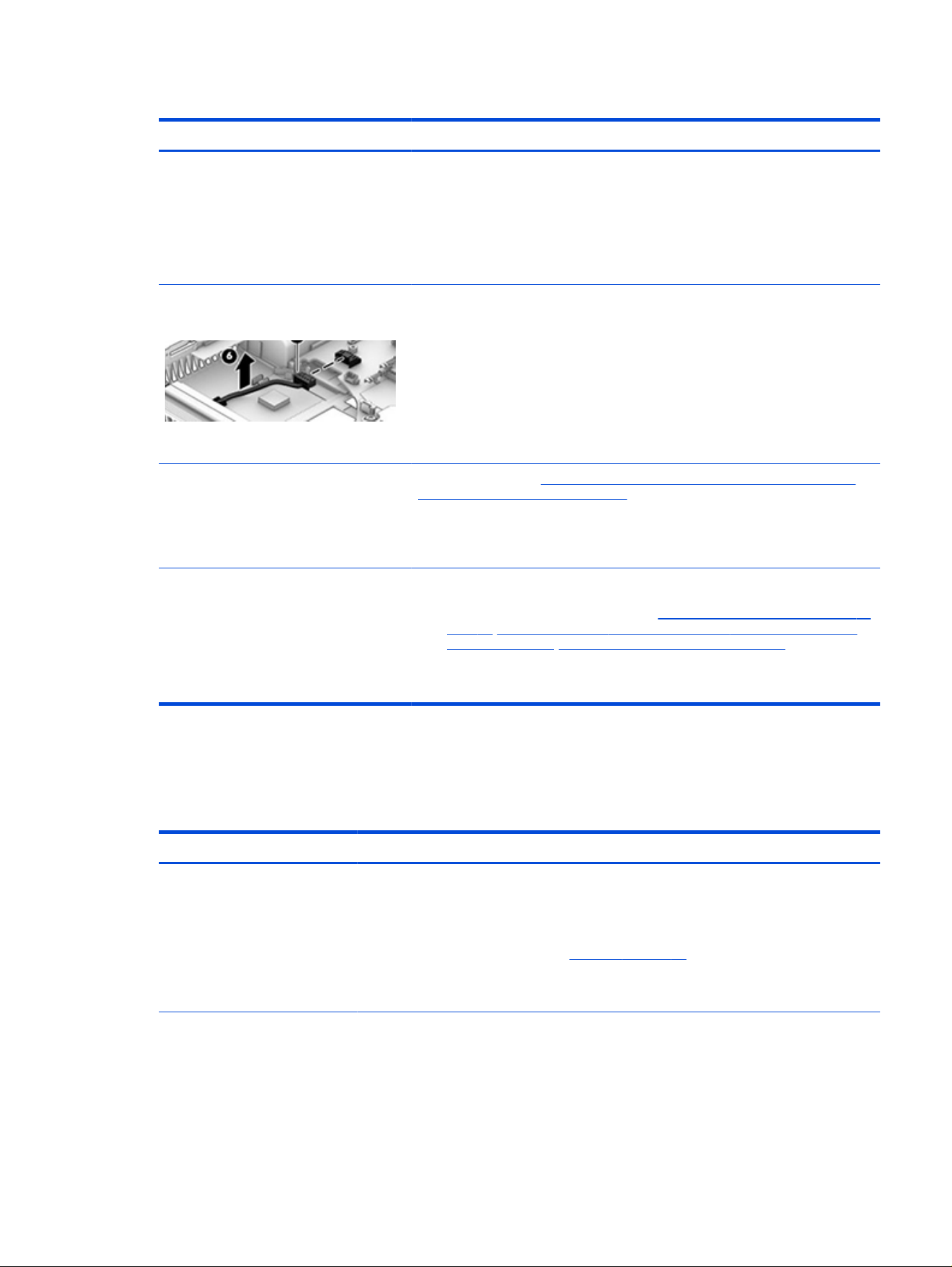
Table 7-9 Issues, possible causes, and xes (continued)
Items Procedures
Verify AC adapter voltage
1. Measure DC voltage output, which should be approximately 19.5 V DC.
Acceptable voltage range is from 18.5 to 20.5 V DC.
2. If the DC voltage is out of range, replace the AC adapter.
NOTE: This action requires a digital voltmeter.
NOTE: Select models include a power
cable between the system board and
chassis power connector.
Verify power button, power connector
1. Be sure that power button is not stuck.
2. Reseat power connector cable (if applicable).
3. Replace new power connector cable (if the cable exists and is defective)
4. To isolate faulty power connector cable and power button, technicians can
short power-on pads or pins to turn on the computer. Contact HP Engineering
for this information.
Verify blinking lights (7. Status lights, blinking light codes, troubleshooting lights,
and POST error messages on page 72)
At this point, there should be sufcient power from the AC adapter to the system
board. Expect to hear the fan spinning and see blinking lights or error messages (for
example, faulty memory, HDD).
Verify system board
1. Test essential hardware conguration (11. Test with minimum conguration on
page 77, 12. Test with veried working conguration (hardware or operating
system) on page 78, 13. Replace the system board on page 78) by removing
nonessential parts.
2. If the computer still does not boot, replace system board.
Intermittent power-on, shutdown, restart
Use this information to troubleshoot power-on, shutdown, and restart issues.
Table 7-10
Issues, possible causes, and xes
Items Procedures
Symptoms
● Does not always turn on
● Intermittently hangs
● Intermittently shuts down
● Spontaneously restarts
Possible causes
Electrical short, uctuating power source, unstable power rails, loose connections, bent pins,
stray wires, dust, obvious damage, nearly faulty parts (bulging or leaking capacitor).
Potentially turn into a no-power issue (No power on page 81).
Intermittent power-on, shutdown, restart 83

Table 7-10 Issues, possible causes, and xes (continued)
Items Procedures
Troubleshooting steps
1. Visually check power ports on both AC adapter and computer sides.
2. Inspect power sources:
a. Verify that the AC adapter is working correctly. Use a conrmed working adapter to
test.
b. Verify that battery is not depleted while system is in the sleep state. Test with a
conrmed working battery.
The following steps are for authorized providers or technicians.
1. Follow actions in No power on page 81.
a. Be sure that AC adapter has correct DC voltage.
b. Verify battery: test with a conrmed working battery.
c. Verify that power button is not stuck.
d. Verify that power connector is not loose.
e. Remedy loose connections and reseat major components (processor, memory,
GPU, hard drive, SSD, and others).
2. Perform visual check for loose connections, bent pins, stray wires, dust, nearly faulty
parts (bulging or leaking capacitor).
3. Test essential hardware conguration (11. Test with minimum conguration on page
77)
a. If system starts, reinstall nonessential hardware one component at a time to isolate
issue.
b. If system does not start, replace essential hardware with veried working parts,
one component at a time. If system still does not start, replace system board.
AC adapter issue
Use this information to troubleshoot AC adapter issues.
84
Chapter 7 Troubleshooting guide

Table 7-11 Issues, possible causes, and xes
Solution
Symptoms
● No sign of power
● No boot
● No rear power light
● No front power light
● Battery does not charge when AC
adapter is connected
Possible causes
AC adapter and others (for example, external power source).
Troubleshooting steps
Quick check
1. Verify external power source (2. Examine the environment on page 68).
2. Remove all external devices, including docking station.
3. Perform a hard reset for the computer (8. Hard reset on page 75).
4. Disconnect and reassemble the power cord and adapter in case the adapter
experienced short circuit, over current, over temperature events.
5. Use a veried working adapter. If the computer operates normally, there is a
problem with the original adapter.
6. Verify that the AC adapter works on a veried working computer. If the
computer operates normally, there is no problem with the adapter. See
HP
Smart Adapter warning message on page 99 for further information.
Verify AC adapter
1. Remove working battery.
2. Verify that AC adapter is compatible with product. Verify that part number is
for this computer if possible.
3. Inspect AC adapter and power cord for physical damage, bent middle ID pin.
4. Plug in AC adapter and power the computer without battery.
5. Inspect the power port on computer side for any damage, dust, debris.
6. Check power light (7. Status lights, blinking light codes, troubleshooting lights,
and POST error messages on page 72). Rear power light indicates that
external power to the computer is good.
7. If there is still no rear power light or no startup, replace the AC adapter.
Tips
The HP Smart AC adapter has a special pin in the middle, called the ID pin, for power
rating and throttling. If this pin is broken, the rear power light turns on, but the power
button and front power lights blink continuously, and the computer does not turn on.
Third-party AC adapters do not work with the computer.
Use the AC adapter that came with the computer for better performance.
Battery not recognized, not charging
Use this information to troubleshoot battery issues.
Battery not recognized, not charging
85

Table 7-12 Issues, possible causes, and xes
Items Procedures
Symptoms
● No battery status light
● Blinking amber (critically low
battery level)
● No startup without AC adapter
Possible causes
Defective AC adapter, battery, or both.
NOTE: Before proceeding, verify that the computer can start to BIOS or Windows with a
good AC adapter.
86 Chapter 7 Troubleshooting guide

Table 7-12 Issues, possible causes, and xes (continued)
Items Procedures
Troubleshooting steps
Visual inspections
1. Inspect battery connectors for any signs of damage.
2. Verify that battery is installed properly in battery bay without gap or obstructions
and latch locks are tight. Reseat battery (for models with removable batteries).
3. Determine whether battery gets hot (batteries heat up when charging, but not too
hot to touch).
Check battery warranty to see whether the battery is new or its warranty is expired.
Battery capacity degrades over time.
Verify front battery status light
1. Battery status light is off: battery not recognized.
2. Battery status light is blinking amber: critically low battery level.
Reset
1. Hard reset (8. Hard reset on page 75)
2. Soft reset (9. Soft reset (Default Settings) on page 76)
Verify AC adapter
1. Determine whether the computer needs the AC adapter to boot and operate.
Sometimes, an intermittently bad AC adapter and loose connection between
adapter and computer results in inability to charge battery, which causes short run
time.
2. Inspect AC adapter to verify that it is functioning.
3. Test with a working AC adapter and conrm whether battery is charging.
4. Be sure that battery is fully charged (AC adapter plugged in at least 2.5 hours).
Diagnostics: HP tools report results such as passed, calibrate, weak, replace, no battery,
and unknown, and they suggest corresponding actions.
HP PC Hardware Diagnostics UEFI is a good tool to use to isolate and determine faulty
battery, especially for quickly discharging (short life) battery.
1. Verify that battery is recognized and charging.
2. Verify battery condition if battery cycle life is past its life expectancy (that is, past
1000-cycle life and 3-year warranty). Battery might need to be replaced.
3. If issue remains, test with a veried working battery and verify battery status lights
and battery conditions.
4. If issue remains, replace system board.
5. Verify the new replacement.
Tips
See the computer user guide for instructions regarding battery maintenance and
increasing battery life.
Battery not recognized, not charging 87

Battery discharges too fast
Use this information to troubleshoot battery issues.
Table 7-13 Issues, possible causes, and xes
Items Procedures
Symptoms
Battery has good status light but
discharges too fast
Possible causes
AC adapter, battery, or both.
Troubleshooting steps
Verify AC adapter
Determine whether the computer needs the AC adapter to boot and operate.
Sometimes an intermittently bad AC adapter and loose connection between
adapter and computer results in the inability to charge the battery and causes
short runtime.
1. Inspect AC adapter to verify that it is working.
2. Test with AC adapter alone and with a veried working AC adapter.
Verify battery: Because battery capacity can degrade over time, check the
warranty coverage. Run a battery test to conrm whether issue is hardware related.
1. Review battery power plans in Control Panel > Power Options that might
consume more energy and discharge battery faster. Resetting default to
Power Saver option can conserve battery power.
2. Determine whether any graphics are processing.
3. Verify battery maintenance and operations. Leaving the battery at a high
level of charge in a high-temperature environment for extended periods
accelerates the loss of capacity.
4. Test and calibrate battery using HP PC Hardware Diagnostics UEFI.
5. Verify battery life cycle using HP Support Assistant tool.
If battery cycle life is past its life expectancy (past the 1000-cycle life and
3-year warranty), the battery might need to be replaced.
6. Compare discharge time with a veried working battery (remove AC adapter)
using Hardware Diagnostics UEFI>Hard Drive Tests>Extensive Test>Loop
until error.
Tips
To conserve battery power, turn off Wireless On-Off button and other peripherals
and USB devices, applications, processes (in Task Manager) when not in use; also,
reduce screen brightness.
Follow HP instructions about how to maintain battery and increase battery life.
Burnt smell
Use this information to troubleshoot burnt-odor issues.
88
Chapter 7 Troubleshooting guide

Table 7-14 Issues, possible causes, and xes
Items Procedures
Symptoms
Emits smoke, burnt smell
Possible causes
Defective on-board components.
Troubleshooting steps
General visual inspection
1. Disconnect the computer from power source (AC adapter and battery).
2. Inspect for visual damage on AC adapter and battery. Test on a known working
computer to isolate issue. If issue follows AC adapter or battery, replace it.
3. Inspect for any sign of liquid spill on the computer (back of keyboard).
The following steps are for authorized providers or technicians.
Further inspection on components
1. Inspect further sources internally after disassembling chassis, such as burnt or
damaged components.
2. If the issue persists, replace boards, AC adapter, and battery for safety concern,
and report issues to HP.
POST
Use the following sections to troubleshoot Power-on Self Test issues.
No video (with power)
Use this information to troubleshoot video issues.
Table 7-15
Issues, possible causes, and xes
Items Procedures
Symptoms
● No video (black or blank image)
but have power
● Light activity
● No error messages
● Fan noise
● Hard drive light blinking and hard
drive noise
Possible causes
Failed display
Failed critical components (memory, hard drive, system board)
Loose connection
Recently added hardware
NOTE: These suggestions assume that the computer has not previously been set up for
multiple displays.
POST 89
Table 7-15 Issues, possible causes, and xes (continued)
Items Procedures
Troubleshooting steps
Quick check
1. Verify that system light activity is OK.
2. Remove all external devices, including docking station. Recently added hardware or
applications might cause graphics driver conict and result in loss of video.
3. Perform hardware reset (8. Hard reset on page 75) and verify that HP Logo is
presented correctly on display screen when pressing f10.
4. Test with external monitor via VGA port (or DisplayPort, HDMI, or other). Press
power button and close the computer lid to force video output to external video.
If unsuccessful, contact HP service.
5. If external video is OK, update BIOS, software, and drivers (4. Update BIOS and
drivers on page 69), and perform soft reset (9. Soft reset (Default Settings) on page
76) if needed. Go to next step to verify display.
Verify display
● When booting to Windows, determine whether image appears on display screen (via
Windows Screen Solutions or Windows logo + p for display switcher).
● If there is video on the display, disconnect external display device, open the
computer lid, and restart.
The following steps are for authorized providers or technicians.
1. Reseat display cable connection on system board.
2. Reseat display cable connection on display panel side.
3. Examine and reseat major components, such as hard drive and memory.
4. Test with minimum conguration (11. Test with minimum conguration on page 77)
by removing hard drive to isolate operating system issues and testing video in F10
Setup.
5. If video is present, restart and retest the computer.
6. If video is present but bad, go to Display on page 101 section.
7. If issue persists (no video), test with external video.
8. If issue persists, test or replace with a conrmed working display.
9. If issue persists, replace discrete graphics card.
10. If issue persists, replace system board because of defective video function.
Tips
Swipe a metal piece (screwdriver) over wireless or mute buttons to act as if closing lid to
force video output to external display device.
Blinking lights
Use this information to interpret blinking lights on the computer.
90
Chapter 7 Troubleshooting guide

Table 7-16 Issues, possible causes, and xes
Items Procedures
Symptoms
Lights blink on keyboard caps
lock/num lock keys
Possible causes
Blinking lights on startup usually indicate a problem with basic functionality of a critical
component (processor, BIOS, graphics cards, memory, and so on) because of a loose
connection, defective parts, or recently added parts.
Troubleshooting steps
1. Check for any blink patterns. Count the number of blinks in a sequence, followed by a
pause for a few seconds.
2. See status, blinking lights, and error message (7. Status lights, blinking light codes,
troubleshooting lights, and POST error messages on page 72) for corrective actions.
3. If internal hardware components (such as memory, hard drive) have been recently
added, a component might not be connected properly. Remove and reseat new
components (10. Reseat cables and connections on page 76) one at a time.
Note Because the display might not be functional, lights are used to indicate an error.
Diagnostic error messages
Use the information in the table to help you understand diagnostic error messages.
Table 7-17
Issues, possible causes, and xes
Items Procedures
Symptoms
● Computer has power
● POST error message displays
(Windows logo has not yet
appeared)
Possible causes
Diagnostic error messages indicate a problem. There might be a problem with the
instruction being sent from the BIOS to a hardware component (for example, keyboard
failures), or incompatible hardware. Can usually be resolved by installing updated
rmware for the component.
Troubleshooting steps
1. See 7. Status lights, blinking light codes, troubleshooting lights, and POST error
messages on page 72 for corrective actions. An example of a POST error message
might be "Boot Device Not Found."
2. If there is power, you might be able to access BIOS. Reset BIOS to its default
condition. (9. Soft reset (Default Settings) on page 76)
3. Restore hardware to its original condition (for example, bootable SSD instead of
hard drive).
4. Reseat suspected components and verify connection.
5. Test suspected components using HP PC Hardware Diagnostics (UEFI) tool.
Note
An Error Message means that the system has nished BIOS hardware validation and
is ready to launch the Startup Menu. To access the Startup Menu for further options,
press the esc key while restarting the computer.
BIOS password
Use the information in the table to troubleshoot BIOS password issues.
Diagnostic error messages
91

Table 7-18 Issues, possible causes, and xes
Items Procedures
Symptoms
Some sections are unavailable
(grayed out)
Possible causes
You must use an administrator password.
Troubleshooting steps
1. Review F10 BIOS Setup Overview to determine which features must be enabled.
2. Your BIOS settings might be managed by a BIOS administrator password setup.
3. If you lost or forgot the user password, contact your IT personnel.
Reference HP F10 Setup Overview
See the HP PC BIOS F10 Setup Guide at http://support.hp.com.
Performance (OS)
Most software problems occur as a result of certain situations.
● The application was not installed or congured correctly.
● There is insufcient memory available to run the application.
● There is a conict between applications.
Be sure that all the necessary device drivers are installed.
If an operating system other than the factory operating system is installed, check whether the operating
system is supported and the application is certied for the version of the operating system.
Intermittent shutdown
Use this information to troubleshoot shutdown issues.
Table 7-19
Issues, possible causes, and xes
Items Procedures
Symptoms
● Shutdown during startup
● Shutdown during operation
Possible causes
It is often difcult to troubleshoot an intermittent issue. Possible causes include:
Power-related issue: defective or insufcient power sources, poor connection.
OS Custom Setting: Energy Saver (Power Management).
Thermal-related issue: thermal sensors reach limits.
Hardware related issue, voltage, out-of-range current, electrical short.
Troubleshooting steps
1. Update BIOS and drivers. (4. Update BIOS and drivers on page 69)
2. Perform hard reset (8. Hard reset on page 75)
3. Perform soft reset (9. Soft reset (Default Settings) on page 76)
92 Chapter 7 Troubleshooting guide

Table 7-19 Issues, possible causes, and xes (continued)
Items Procedures
Power-related issue
1. Verify functionality of AC adapter alone. If it does not work, test with a veried
working adapter.
2. Verify battery alone. Verify that battery is not depleted. Test battery using HP PC
Hardware Diagnostics (UEFI) tool.
3. Verify connection of power button and cable.
OS custom settings
1. Advise users to reset power options and close all applications that are not in use,
including applications in the background.
2. Test with a conrmed working operating system to isolate custom settings by users
or any conicting applications that cause shutdown.
The following steps are for authorized providers or technicians.
Thermal-related issue
1. Verify thermal condition:
a. Test fan using HP PC Hardware Diagnostics (UEFI) tool.
b. Check fan and connection. Reseat fan cable.
c. Be sure that no obstructions or dust are in heat sink fan, n, or vent.
d. Test with a veried working fan.
e. Remove old thermal compound and pads and replace with new compound and
pads.
2. Verify thermal solution:
Use Thermal Monitor tool (available only to authorized service providers/
technicians) to perform stress test (processor and GPU), and verify that thermal
sensors are within limits after thermal condition is serviced.
Hardware-related issue
1. Check for any signs of loose connections, bent pins, stray wires, dust, nearly faulty
parts (bulging/leaking capacitor).
2. Verify that lights are solid.
3. If shutdown is reproducible, test essential hardware conguration:
a. If no issue with hardware conguration, reinstall one nonessential component
at a time to determine faulty hardware.
b. If issue persists, replace essential hardware with a conrmed working part, one
at a time. If the computer does not boot, replace system board.
Tips Intermittent issues are difcult to reproduce and troubleshoot. It is important to record
details about shutdown frequencies, system conguration (3D video application), and
operating conditions.
Blue screen
Use this information to troubleshoot blue screen issues.
Blue screen
93
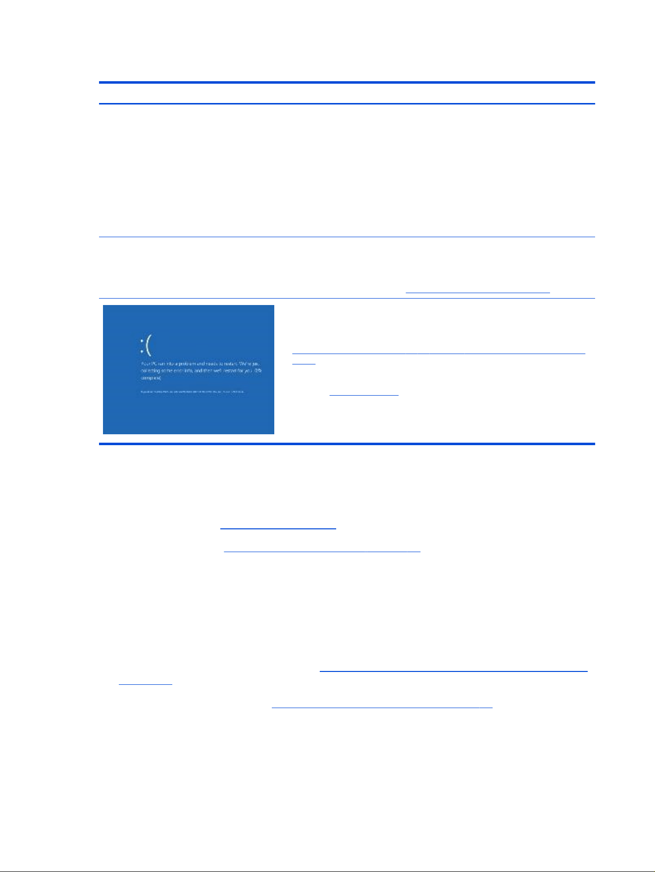
Table 7-20 Issues, possible causes, and xes
Items Procedures
Symptoms
● Has power, light activity, fan spinning
● HP Logo displays briey
● Fails to boot into Windows operating
system, displays blue screen, and then
crashes, restarts, or stops responding
Possible causes
Recent changes: conicting instructions from multiple programs or recently
added hardware.
Incompatible hardware and driver.
Poor connection (hard drive, memory).
Hardware malfunctioning due to overheating (GPU, processor).
Defective hardware (memory, hard drive).
Important Notes & Resources Troubleshooting steps
There are many different ways to troubleshoot a blue screen error. Therefore,
you need to identify working conguration and specic symptoms of the failure
to narrow down the issue. See Blue screen (BSOD) error on page 120.
Recommended resources
Microsoft knowledge base:
http://windows.microsoft.com/en-us/windows-8/resolve-windows-blue-screen-
errors
For more information, search for HP Troubleshooting Error Messages on a blue
screen at http://www.hp.com.
Overview of general troubleshooting steps for a blue screen error
1. Note the blue screen error message and what activity was performed at the time.
2. Perform a hard reset (8. Hard reset on page 75) after disconnecting all external peripherals.
3. Reset BIOS to default (9. Soft reset (Default Settings) on page 76) to prevent booting to another
device.
4. Run HP Hardware Diagnostics to isolate major faulty hardware issues.
● HP PC Hardware Diagnostics (UEFI) tool to test hard drive, memory, and system.
● Thermal Monitor (available only to authorized service providers and technicians) tool to monitor
temperature limits of processor and GPU.
5. Remove or undo recently added hardware (5. Remove or uninstall recently added hardware, software
on page 69). For example, incompatible memory or new SSD storage.
6. Reseat cables and connections (10. Reseat cables and connections on page 76). Pay attention to
proper installation of memory and hard drive.
7. Verify that a minimum of at least 100 MB of free space is available on your Windows partition.
8. If you can start Windows:
94
Chapter 7 Troubleshooting guide

a. Update BIOS and drivers (4. Update BIOS and drivers on page 69) to support updates for
incompatibilities.
b. Get all the latest updates, using Windows Update.
c. Undo recent changes:
● Startup using Last Known Good Conguration.
● Use System Restore.
● Roll back device driver in Device Manager.
d. Check for specic Error Message. See Common blue screen error messages on page 129.
e. Start in safe mode (11. Test with minimum conguration on page 77) to troubleshoot issues.
9. If you cannot start Windows:
a. Start in safe mode. (11. Test with minimum conguration on page 77)
b. Use Startup Repair to x Windows startup les.
c. Undo recent changes using System Restore to revert to a previous working state.
d. Check for specic STOP error by analyzing Crash Dump (retrieved via a bootable USB). See Use
Windows Debugging Tool on page 130.
e. Restore computer using System Recovery or image backup to factory settings.
10. Test with essential hardware conguration (11. Test with minimum conguration on page 77) with
a veried working operating system (for instance, USB Windows-To-Go), if available, to isolate the
software issue.
Freeze at Windows Logo (hang or lockup)
Use the following information to troubleshoot hang or lockup issues.
Freeze at Windows Logo (hang or lockup)
95

Table 7-21 Issues, possible causes, and xes
Items Procedures
Symptoms
● Has power, light activity, fan spinning
● HP Logo displays briey
● Attempt to start to operating system and
freeze/hang at Windows logo
● No response to pressing num lock or
caps lock key
Possible causes
Conict of instructions from multiple programs or drivers; installing a new
hardware or program that is not compatible (might also cause a blue screen
error—see blue screen issue).
Troubleshooting steps
Perform the following steps to verify normal boot process:
1. Disconnect all external peripherals, and perform a hard reset (8. Hard reset
on page 75).
2. Perform soft reset (9. Soft reset (Default Settings) on page 76).
3. Update BIOS and drivers (4. Update BIOS and drivers on page 69).
a. Rollback to previous version might be necessary.
b. Go to safe mode to install drivers.
4. Run Hardware Diagnostics to isolate hardware issue.
5. Undo recent changes in Windows (5. Remove or uninstall recently added
hardware, software on page 69).
6. Reseat cables and connections (10. Reseat cables and connections on
page 76).
7. Start Windows in safe mode (11. Test with minimum conguration on page
77).
8. Use Startup Repair Windows to x Windows damaged les.
9. Test with essential hardware conguration (11. Test with minimum
conguration on page 77) with a veried working operating system (for
instance, USB Windows-To-Go), if available, to isolate the software issue.
Electromagnetic Interference (EMI)
Use this information to troubleshoot EMI issues.
96
Chapter 7 Troubleshooting guide

Table 7-22 Issues, possible causes, and xes
Items Procedures
Symptoms
System locks up, freezes in certain
physical area or location
Possible causes
Electromagnetic interference (EMI).
Troubleshooting steps
1. See (2. Examine the environment on page 68). Pay attention to external power source,
high-frequency signals such as cell phones, microwave ovens.
2. Move the computer to different locations nearby to determine where it fails and where
it does not fail.
3. Test with a veried working computer in original factory conguration.
4. Consult with support.
No wake up
Use this information to troubleshoot wake-up issues.
Table 7-23 Issues, possible causes, and xes
Items Procedures
Symptoms
When resuming from a power
management state the computer
might display:
● Blank screen
● Some light activity
Possible causes
Power-saving mode; multiple-display setting.
No wake up 97
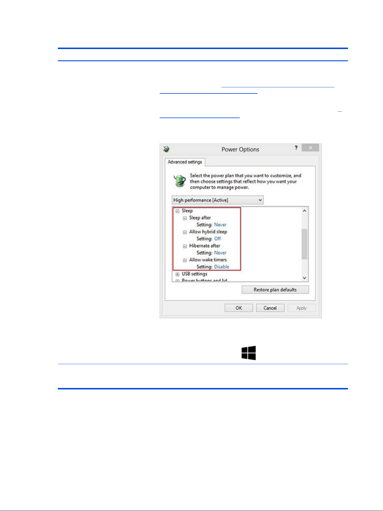
Table 7-23 Issues, possible causes, and xes (continued)
Items Procedures
Troubleshooting steps
1. Verify that front power light (7. Status lights, blinking light codes, troubleshooting
lights, and POST error messages on page 72) is blinking (indicating sleep state).
Press power button to exit sleep.
2. Reset BIOS to default (associated with OS Power Management in Power Menu) (4.
Update BIOS and drivers on page 69)
3. Check power management settings in Windows Power Options. Disable sleep
options if the issue is resolved.
4. Screen saver is set. Press any key or touch touchpad to resume.
5. Verify that Display Choice is set to external video only. Toggle screen control key
combination fn + f4 or Windows logo +P.
Tips
If you are using a docking station, set your notebook display as the primary display. When
the computer is undocked, you might think it is in a power-saving state, but the screen
image could actually appear on an external display device in the docking conguration.
Unresponsive
Use this information to troubleshoot issues with responsiveness.
98
Chapter 7 Troubleshooting guide

Table 7-24 Issues, possible causes, and xes
Items Procedures
Symptom
Unresponsive
Possible causes
Program in use has stopped responding to commands.
Troubleshooting steps
1. If possible, use the Windows Task Manager to isolate and terminate the offending
process.
2. Attempt the normal Windows shutdown procedure.
3. Restart the computer using the power button.
Slow performance
Use this information to troubleshoot performance issues.
Table 7-25 Issues, possible causes, and xes
Items Procedures
Symptom
Slow performance when performing
small tasks, or even in idle mode
Possible causes
Processor is hot or hard drive is full.
Troubleshooting steps
Processor is hot
1. Verify that airow to the computer is not blocked.
2. Verify that chassis fans are connected and working properly. Some fans operate
only when needed.
3. Verify that the processor heat sink is installed properly.
Hard drive is full
1. Transfer data from the hard drive to create more space on the hard drive. Microsoft
recommends at least 200 MB to sync system les.
2. Perform disk defragmentation to consolidate fragmented data on the hard drive so it
works more efciently.
Tips See Routine maintenance for performance improvement on page 128.
See http://windows.microsoft.com/en-us/windows-8/free-up-disk-space.
See http://windows.microsoft.com/en-us/windows/optimize-windows-better-
performance#optimize-windows-better-performance=windows-vista.
HP Smart Adapter warning message
Use this information to troubleshoot power adapter warning messages.
Slow performance
99
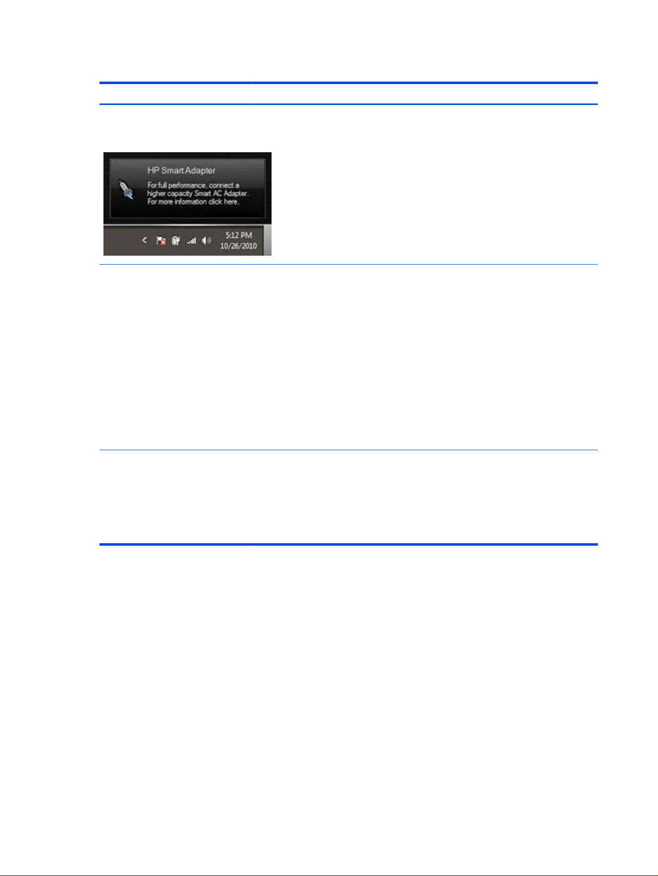
Table 7-26 Issues, possible causes, and xes
Items Procedures
Symptom
Warning message appears in window
Possible causes
Less powerful AC adapter, BIOS out of date.
Troubleshooting steps
1. Update BIOS, which might contain information that assigns an appropriate adapter
for the conguration.
2. Update the latest HP Hotkey Support software from Drivers website.
3. Be sure that the power source is sufcient (where adapter is connected).
4. Use appropriate AC adapter (often supplied with system) for optimum system
performance.
5. Test with a veried working AC adapter.
6. Test the adapter on a veried working computer.
7. Contact HP for conguration details.
Note
HP Smart AC adapter warning message: informs you that as power demands increase,
the notebook might not perform at full capacity, which might result in longer battery-
charging time. In cases of extreme power demands, the system might also throttle back
the processor, or with systems that have a discrete video subsystem, a video balance
mode might occur to further balance the power needs of the system.
Because system processor functions always have priority over battery charging,
charging delays occur rst.
Incorrect time and date
Use the following information to troubleshoot time and date issues.
100
Chapter 7 Troubleshooting guide

Table 7-27 Issues, possible causes, and xes
Item Procedure
Symptom
Incorrect date and time
Possible cause
System disconnected from the AC adapter and system battery power drained.
Troubleshooting steps
1. Connect the AC adapter to the computer.
2. Let the battery recharge.
3. Connect to the internet to synchronize the current time.
Possible cause
System disconnected from the AC adapter and system battery malfunction.
Troubleshooting steps
1. Replace the battery.
2. Connect to the internet to synchronize the current time.
Display
Use these sections to troubleshoot display issues.
Display anomalies
The display panel is a eld-replaceable unit (FRU) and must be replaced only by authorized technicians.
However, HP highly recommends that users and technicians observe symptoms and use the HP PC
Hardware Diagnostics (UEFI) tool before any replacement.
Symptom
This section includes common display issues with symptoms.
● Blank or black video
● Incorrect color, missing color, distorted image
● Flickering image
● Vertical lines (because of LDVS, decreased signal integrity, and data loss)
● Dead pixel (because of display liquid, internal transistor, and others)
● Horizontal lines (because of video memory)
● Distorted when hot (because of thermal issue)
● Cracked screen/image (physical damage)
● Light leakage/bleeding
Contact support for assistance.
● Humming noise (due to frequency settings)
Display
101
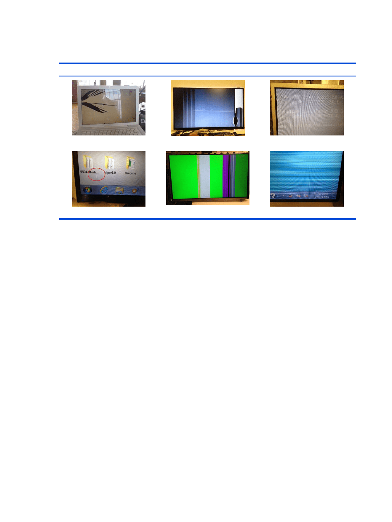
Contact support for assistance.
Table 7-28 Display anomaly illustrations
Display anomalies
Cracked screen
Cracked image
Blurred image
Dead pixel
Vertical lines
Horizontal lines
Quick check
Use these steps to check the display.
● Visually examine the display for cracked screen, liquid crystal leak, dirty spots on glass, and other
issues.
● Reset and update BIOS and docking rmware.
● Update operating system (OS), graphics or video drivers (Intel, AMD, NVIDIA, and others).
For custom images, HP highly recommends upgrading or installing Windows in UEFI mode or Legacy
disabled to fully support hybrid graphics and avoid unexpected behaviors, for example, blue screen
error, graphics or video issues, in the BIOS Legacy setting.
● Congure Windows settings (Power options, Screen brightness, Personalization, Screen resolution,
and so on).
● Test with a veried working external display.
● Boot to Windows in safe mode.
● Test with a veried working operating system (for instance, shipping image).
HP PC Hardware Diagnostics (UEFI) for video test
Use this tool to quickly determine if the display issue is related to a real hardware issue.
To start HP PC Hardware Diagnostics (UEFI), when the computer is starting up, press the f2 key, select
Component Tests, and then select Video.
102
Chapter 7 Troubleshooting guide
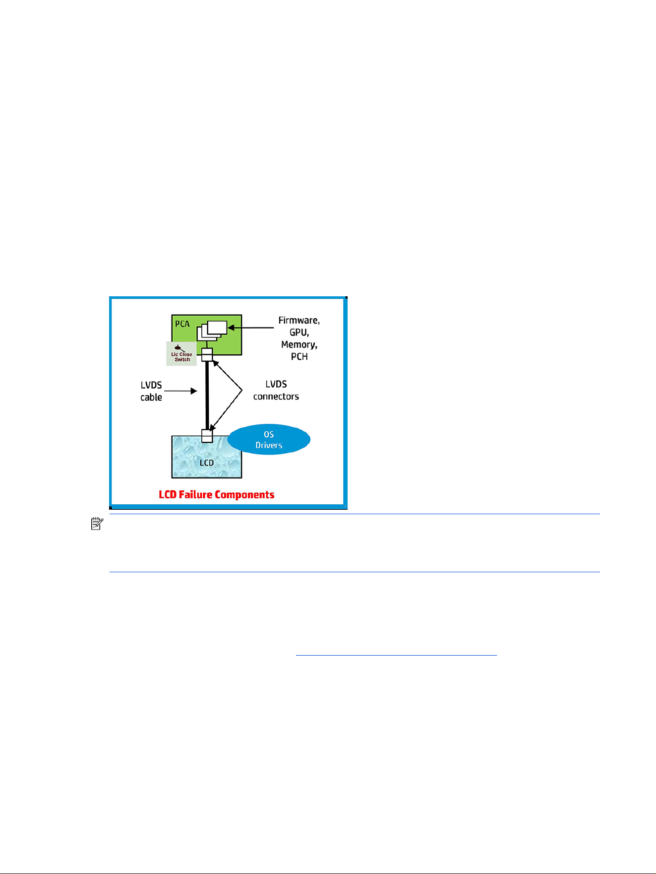
There are three options:
● Video Memory Check: to test video memory
● Palette Check: to test the three video color components (red, green, blue)
● Dead Pixel Check: to check dead pixels in eight different colors (Dead Pixel Check is available with the
HP PC Diagnostics 3-in-1 USB Key tool)
Review the video troubleshooting in the following Display section for specic issues and possible
solutions. For additional information about display problems, see documentation provided by the product
manufacturer.
Display assembly diagram
The display assembly diagram shows basic video components: system board, graphics cards, display
cables, display connectors, operating system (OS), graphics driver, and LCD display panel. Any component
or a combination of these components can contribute to a video issue.
NOTE: The lid close switch is a Hall-effect sensor located in the top cover. When the display is closed,
the sensor acts like a switch is closed. A notebook can force a video output to an external monitor, or go
to hibernation or standby mode through power management. If the display screen does not light up when
the display is open, the lid close switch (Hall-effect sensor) could be faulty.
Dead pixel
Display panel might show one or more pixels that are not properly lit when displaying a single color over
the screen area. Use HP PC Hardware Diagnostics (UEFI) tool to determine those defective pixels.
There is no solution for dead pixels. See Display issue: pixel anomalies on page 134 for the HP dead pixel
policy.
No video (internal)
Use this information to troubleshoot video issues.
Display assembly diagram
103

Table 7-29 Issues, possible causes, and xes
Items Procedures
Symptoms
No internal video with certain
programs (for example, video-
intensive games)
Possible causes
Display resolution, brightness, faulty lid switch, running a program requiring a higher
resolution than the display screen can support.
Faulty lid switch might put the system into sleep or hibernation mode.
Troubleshooting steps
Use an external monitor with higher resolution.
Test with external monitor using HDMI or HP port. Press the power button and close the
computer lid to force video output to external video. If there is still no video, contact
support.
References See section No video (with power) on page 89 for display information.
No video (external)
Use this information to troubleshoot external video issues.
Table 7-30 Issues, possible causes, and xes
Items Procedures
Symptom
No image on external monitor
Possible causes
External monitor, resolution, display conguration, drivers.
Troubleshooting steps
1. Be sure external monitor is compatible with the computer.
2. Be sure that external monitor is turned on.
3. Press any key to exit the power-saving mode.
4. Adjust the brightness of the monitor.
5. Test with a veried working monitor.
6. Test the monitor via internal ports (VGA, DP ports).
7. Install latest video driver.
8. Reset the screen resolution as described in the documentation.
9. Congure display choice, and then force output to external video by closing the
notebook lid or pressing fn + f4 to switch screen output.
DisplayPort/VGA
Use this information to troubleshoot DisplayPort and VGA issues.
See No video (external) on page 104.
HDMI
Use this information to troubleshoot HDMI issues.
104
Chapter 7 Troubleshooting guide

Table 7-31 Issues, possible causes, and xes
Items Procedures
Symptoms
● Display issue
● Sound issue
Possible causes
Cable, connection, settings.
Troubleshooting steps
Quick Check
1. Verify that the HDMI device input source is set correctly (for example, HDMI1).
2. Be sure you are using the correct HDMI cable.
3. Check connection and reconnect the HDMI cable.
4. Verify whether sound output is congured correctly in Control Panel > Sound
Manager.
1. Perform hard reset (4. Update BIOS and drivers on page 69).
2. Update BIOS and drivers (4. Update BIOS and drivers on page 69) when you hear sound
but do not see video on HDTV.
No or bad external video via docking
Use this information to troubleshoot video issues while docking.
Table 7-32
Issues, possible causes, and xes
Items Procedures
Symptoms
No or bad image on external monitor
via ports of docking station (such as
VGA, DP, TB, display port, and others)
Possible causes
Rooted from system board, software or drivers, dock connectors, docking station
hardware or rmware, dock video ports (DP, VGA, and others).
No or bad external video via docking 105

Table 7-32 Issues, possible causes, and xes (continued)
Items Procedures
Troubleshooting steps
1. Be sure that external monitor is turned on.
2. Be sure that external monitor is compatible with the computer.
3. If applicable, plug the dock into different Type-C ports.
For more information, see the technical whitepaper titled ”HP Elite Dock with
Thunderbolt 3 & HP ZBook Dock with Thunderbolt 3.” Go to http://www.hp.com/ and
search for HP ZBook Thunderbolt 3 Dock User Guide.
4. If the screen image is distorted, try a DP-to-VGA adapter. Connect the adapter to
each DisplayPort and VGA port of the dock.
5. Test the monitor via internal ports (such as VGA, DP, HDMI, and others).
6. Verify that dock connectors of the notebook and the dock are clean, without dust,
debris (for example, using air duster).
7. Ideally, use a veried working operating system or system connected to the dock to
isolate the issue of the current operating system.
8. Ideally, use a veried working docking station to isolate the faulty dock.
9. Update to latest dock rmware. Follow the installation instructions carefully. You may
want to try a DP-to-VGA adapter if you have a distorted screen image. Connect the
adapter to each DisplayPort of the dock. If you still cannot update the dock, attempt
to update it on a
conrmed working notebook before having the dock replaced.
Note
See the technical whitepaper titled “Multiple displays on HP ZBook Mobile Workstations”
from HP platform support website. Go to http://h20195.www2.hp.com/v2/getpdf.aspx/
4aa5-2657enw.
Incorrect or missing color/distorted image
Use this information to troubleshoot image issues.
Table 7-33
Issues, possible causes, and xes
Items Procedures
Symptoms
System works normally but the
display shows:
● Missing or strange color
● Image distortion
Possible causes
Loose connection, display cable, display, graphics card.
Troubleshooting steps
Verify with external monitor
1. Use combination fn + f4 to enable output to external monitor.
2. Close the lid.
If the external monitor also shows incorrect color, it is a graphics card issue. Test with a
veried working graphics card.
106 Chapter 7 Troubleshooting guide

Table 7-33 Issues, possible causes, and xes (continued)
Items Procedures
Verify monitor cable and cable connection (monitor disassembly required).
Be sure the monitor cables are not pinched or damaged.
Be sure the monitor cables have good connection at both ends (system board and display
panel).
● If moving cables affects the image, the monitor cable is the cause of the issue. Test
with a conrmed working cable.
● If moving cables does not affect the image, the monitor has an issue. Test with a
conrmed working monitor.
Touch screen
Use this information to troubleshoot touch screen issues.
Table 7-34 Issues, possible causes, and xes
Items Procedures
Symptoms
Unresponsive
Inaccurate
Possible causes
Dirt and smudge, driver, touch display conguration, power management.
Troubleshooting steps
Quick check
Turn off the computer, spray glass cleaner onto a soft, damp cloth, and gently
wipe the screen to remove dirt and smudge.
NOTE: Do not spray cleaner directly onto the screen.
Touch screen 107
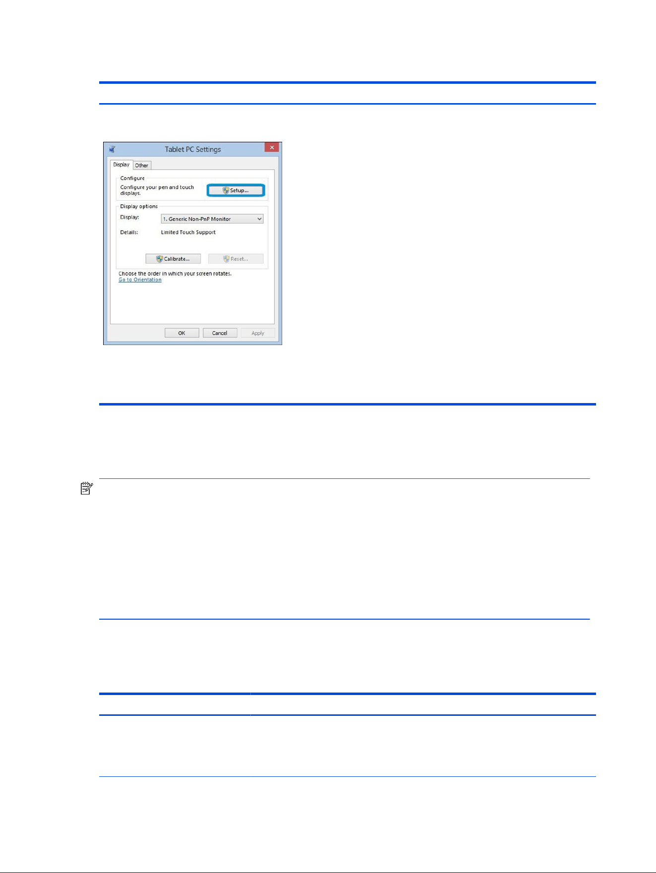
Table 7-34 Issues, possible causes, and xes (continued)
Items Procedures
Congure the touch display in Control Panel >
Tablet PC Settings
1. Restart the computer.
2. Verify touch screen and graphics drivers.
3. Congure the touch display to identify the screen as a touch screen, as
shown in the image at left.
4. Calibrate the screen and reset if touch functionality is still not working
correctly.
5. Perform diagnostic test in HP Hardware Diagnostics under Component
Tests > Touch Screen.
If the diagnostics tests pass but the touch screen still does not respond,
continue following the steps.
6. Adjust the power management settings for your touch screen.
If the touch screen stops working after waking from sleep, adjust the
power management settings so that the touch screen device stays active
while the computer is in sleep mode.
7. Perform Microsoft System Restore, and restore to a time when the system
was working.
8. Perform HP System Recovery if none of the previous actions resolve the
issue.
I/O devices
Use this information to troubleshoot I/O device issues.
NOTE:
● Be sure that external devices are supported and compliant (for example, USB Type-C, Thunderbolt,
PCI Express).
● If you have problems with external devices not provided by HP, contact device manufacturers
for compatibility and latest drivers before troubleshooting (for example, USB devices, Thunderbolt
devices, PCI express card reader, VGA, display, HDMI monitors, speakers).
● Be sure I/O devices are properly inserted into the I/O ports, and then be sure that Windows Device
Manager recognizes the I/O devices.
Keyboard
Use this information to troubleshoot keyboard issues.
Table 7-35
Issues, possible causes, and xes
Items Procedures
Symptoms
Keystrokes not recognized
Characters not matched
Possible causes
Dust trapped under keycap, loose keycap, loose keyboard connection, defective keyboard.
108 Chapter 7 Troubleshooting guide

Table 7-35 Issues, possible causes, and xes (continued)
Items Procedures
Troubleshooting steps
1. Inspect the keyboard for any signs of dust, liquid, or debris trapped under sticky keys
that might prevent keystroke recognition.
2. Check for incomplete connection between keyboard and system board by verifying
that caps lock or num lk light turns on when you press the key.
3. Verify whether the keyboard is recognized in Windows Device Manager, and verify
whether the keyboard driver is installed properly.
4. Test with a working external keyboard (such as a USB keyboard).
Also test in Windows for special keys (caps lock, shift, ctrl, fn, Windows, alt) if
necessary.
5. Test with HP PC Hardware Diagnostics (UEFI) to isolate a hardware issue from a
software issue.
6. Verify that BIOS is up to date. If so, resetting BIOS to default might help.
7. Test with a veried working operating system, or restore the operating system to be
sure that the issue is not caused by items such as different language settings, sticky
keys feature, and so on.
8. Verify that keyboard ex cables are fully inserted and in good condition.
The following steps are for authorized providers and technicians.
1. Verify that keyboard ex cable is in good condition (no delamination or torn cable
end, no missing or cracked tracks, pads).
2. Verify that keyboard ex cable ends are fully inserted and aligned with connectors
on system board, and those connector tabs are properly closed. Reseat cables.
3. Replace new internal keyboard and retest.
Tips If a key works only when pressed with force, inspect and remove debris trapped under
keycap.
Keyboard pointing stick (select products only)
Use this information to troubleshoot pointing stick issues.
Table 7-36
Issues, possible causes, and xes
Items Procedures
Symptom
Pointing stick not working properly
Possible causes
Dust trapped under pointing stick, loose pointing stick cap.
Troubleshooting steps
1. Inspect for any signs of dust or liquid spill that prevent pointing stick from working.
2. Check whether pointing stick cap is loose, and reseat it if necessary.
The following steps are for authorized providers and technicians.
Keyboard pointing stick (select products only) 109
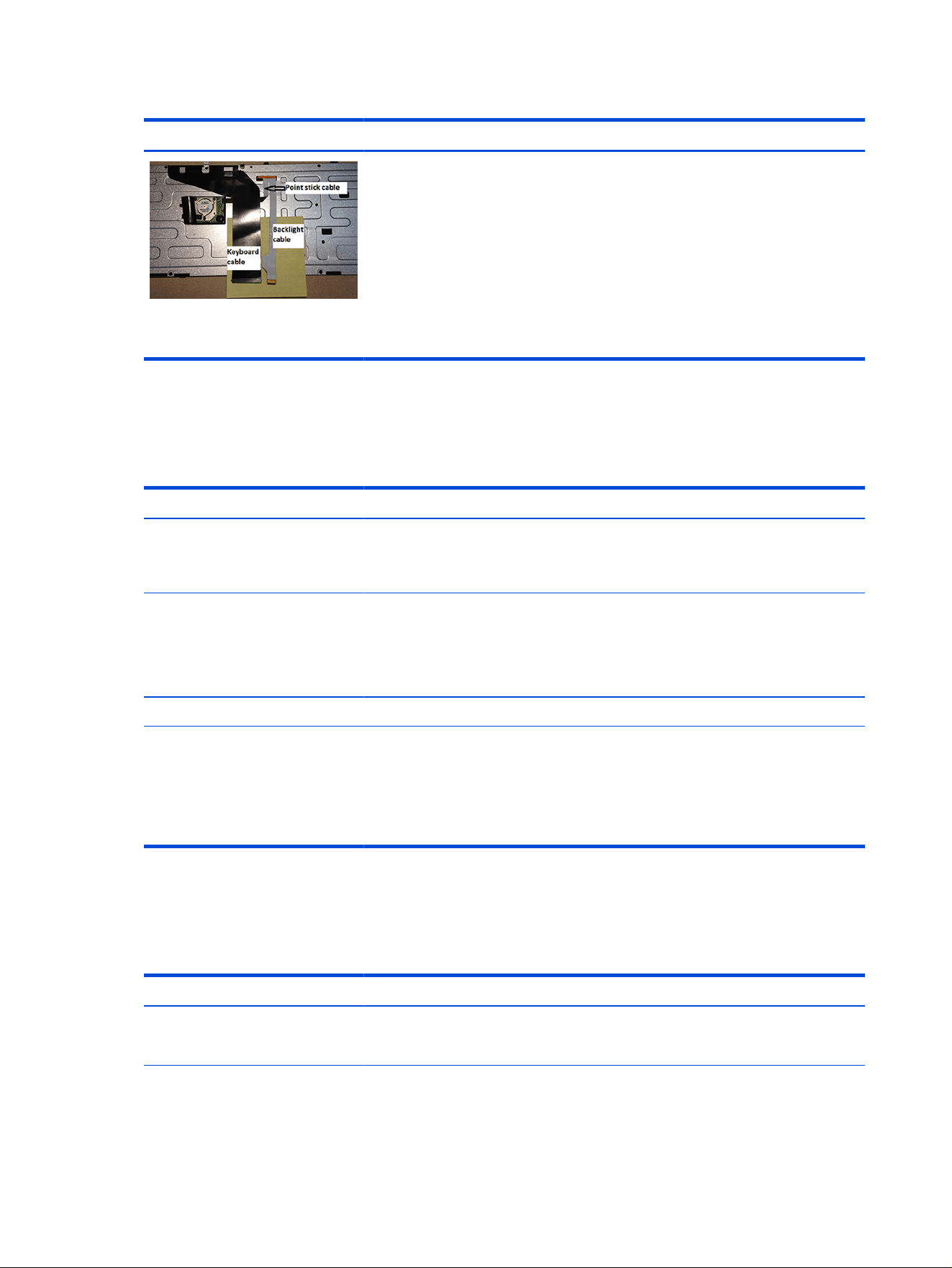
Table 7-36 Issues, possible causes, and xes (continued)
Items Procedures
Example of back of keyboard,
including keyboard, pointing stick, and
backlight cables.
1. Verify whether keyboard ex cables are in good condition (no delamination or torn
cable end, no missing or cracked tracks, pads).
2. Verify that keyboard ex cable ends are fully inserted and aligned with connectors
on system board and back of keyboard, and that connector tabs are properly closed.
3. Reseat pointing stick cables.
Keyboard backlight
Use this information to troubleshoot keyboard backlight issues.
Table 7-37 Issues, possible causes, and xes
Items Procedures
Symptom
Backlight function not working
properly
Possible causes
Backlight disabled, loose connection.
Troubleshooting steps
NOTE: Not all notebook computers have backlit keyboards.
A keyboard function key lets you turn the light on and off. Verify whether backlit feature is
not disabled by pressing a combination of fn + backlit key.
The following steps are for authorized providers or technicians.
1. Verify whether backlight ex cables are in good condition (no delamination or torn
cable end, no missing or cracked tracks or pads).
2. Verify that backlight ex cable ends are fully inserted and aligned with connectors
on system board and that connector tabs are properly closed.
3. Reseat backlight cable.
Touchpad
Use this information to troubleshoot touchpad issues.
Table 7-38
Issues, possible causes, and xes
Items Procedures
Symptoms
Not working properly
Possible causes
Touchpad turned off, driver, settings.
110 Chapter 7 Troubleshooting guide
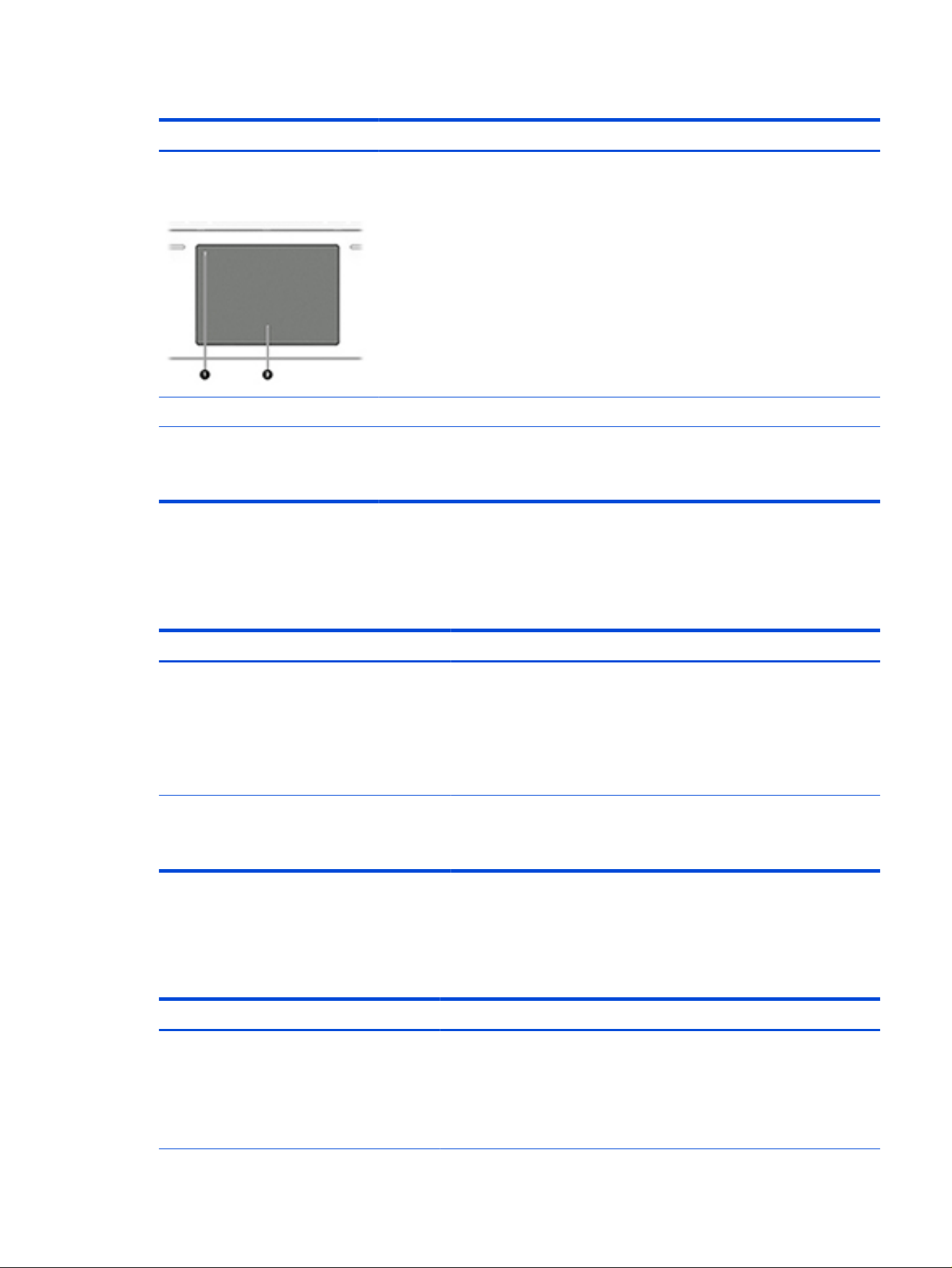
Table 7-38 Issues, possible causes, and xes (continued)
Items Procedures
(1) Touchpad on/off button
(2) Touchpad
Troubleshooting steps
1. Ensure touchpad on/off light is not amber (disabled). Double tap to enable.
2. Verify whether touchpad device is listed in Device Manager > Mice and other
pointing devices.
3. Install the latest touchpad driver.
4. Adjust touchpad settings (Control Panel > Mouse).
5. Test touchpad controller using the HP PC Hardware Diagnostics (UEFI) tool (f2>
Component Tests > Mouse Test > Pointer Test & Drag and Drop Test).
The following steps are for authorized service providers/technicians.
1. Check the touchpad cable for damage or a loose connection, and then reseat the
touchpad cable.
2. If issue persists, replace the touchpad and verify the change.
Network connectivity (RJ-45 jack)
Use this information to troubleshoot network issues.
Table 7-39
Issues, possible causes, and xes
Items Procedures
Symptoms
● Unable to nd networks (yellow warning
symbol, or bang.)
● Connection dropouts
● Slow performance
Possible causes
Network source, cable, connection, RJ-45 (network) jack, driver, settings.
Troubleshooting steps
Quick Check: verify the network status lights that are supposed to ash
when there is network activity.
Network connectivity wireless (WLAN)
Use this information to troubleshoot wireless connectivity issues.
Table 7-40
Issues, possible causes, and xes
Items Procedures
Symptoms
● Unable to nd networks (yellow bang)
● Connection dropouts
● Slow performance
Possible causes
Network source, cable, connection, wireless module, driver, settings.
Network connectivity (RJ-45 jack) 111
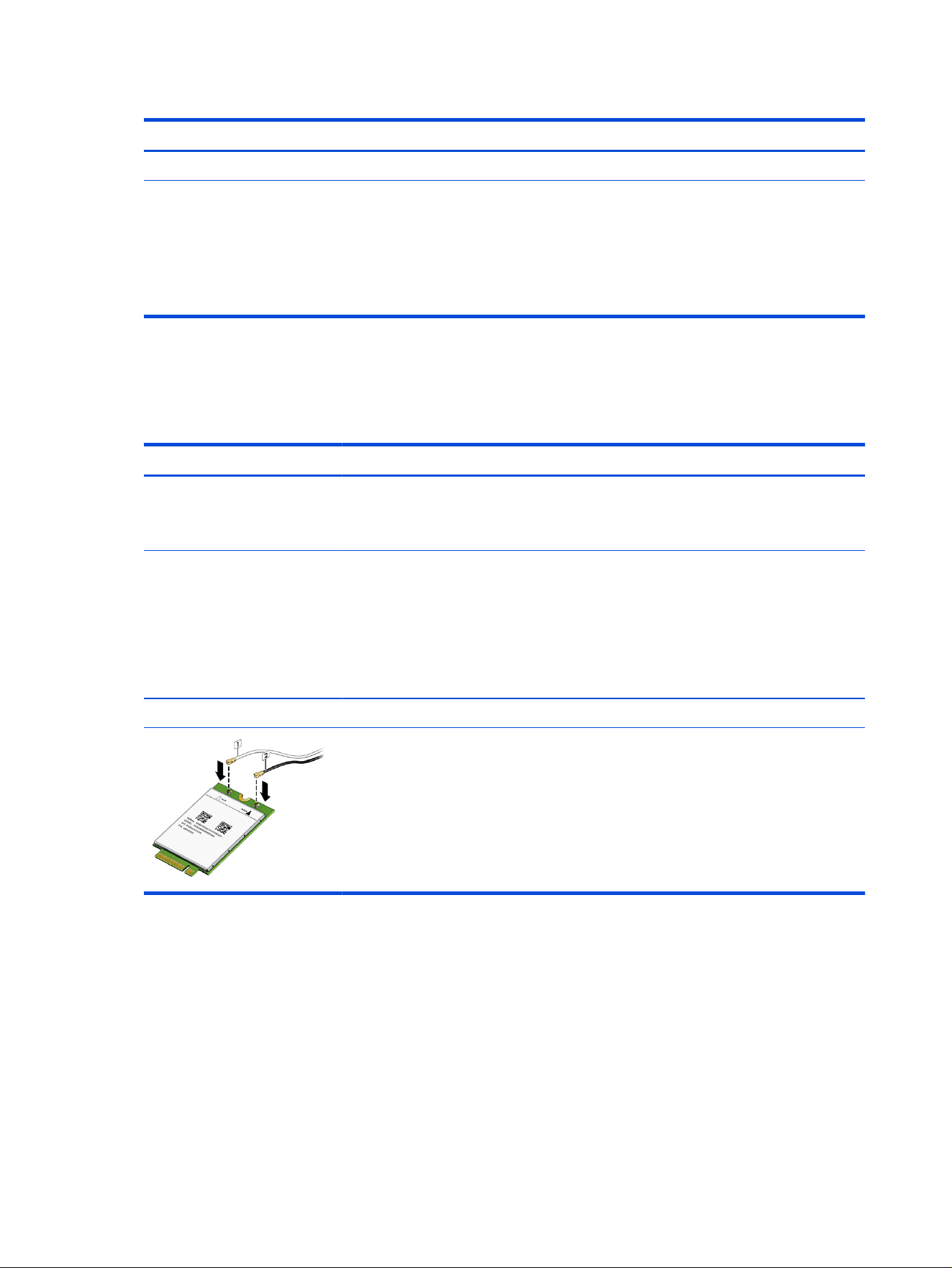
Table 7-40 Issues, possible causes, and xes (continued)
Items Procedures
The following steps are for authorized providers or technicians.
1. Verify that the wireless module and its antenna cables are fully inserted
and in good condition (see WLAN module removal and replacement
section). Reseat wireless module and antenna connection.
2. Verify the module antenna cable connection is not loose.
3. Verify that antenna cables are properly connected to the MAIN and AUX
terminals (see WLAN module removal and replacement section).
WWAN
Use this information to troubleshoot WWAN issues.
Table 7-41 Issues, possible causes, and xes
Items Procedures
Symptom
Unable to nd networks or
service
Possible causes
Network source, cable, connection, driver, settings.
Troubleshooting steps
1. Update to the latest driver and utility.
2. Check with network service provider for signal coverage.
3. Be sure signal strength is good.
4. Be sure that your service is active.
The following steps are for authorized providers or technicians.
● Verify module and antenna cable connections are not loose.
● Verify antenna cables are properly connected to the correct terminals. For example, the
antenna cable labeled 1 connects to the Main terminal labeled 1. The antenna cable
labeled 2 connects to the Aux terminal labeled 2.
USB
Use this information to troubleshoot USB port issues.
112
Chapter 7 Troubleshooting guide
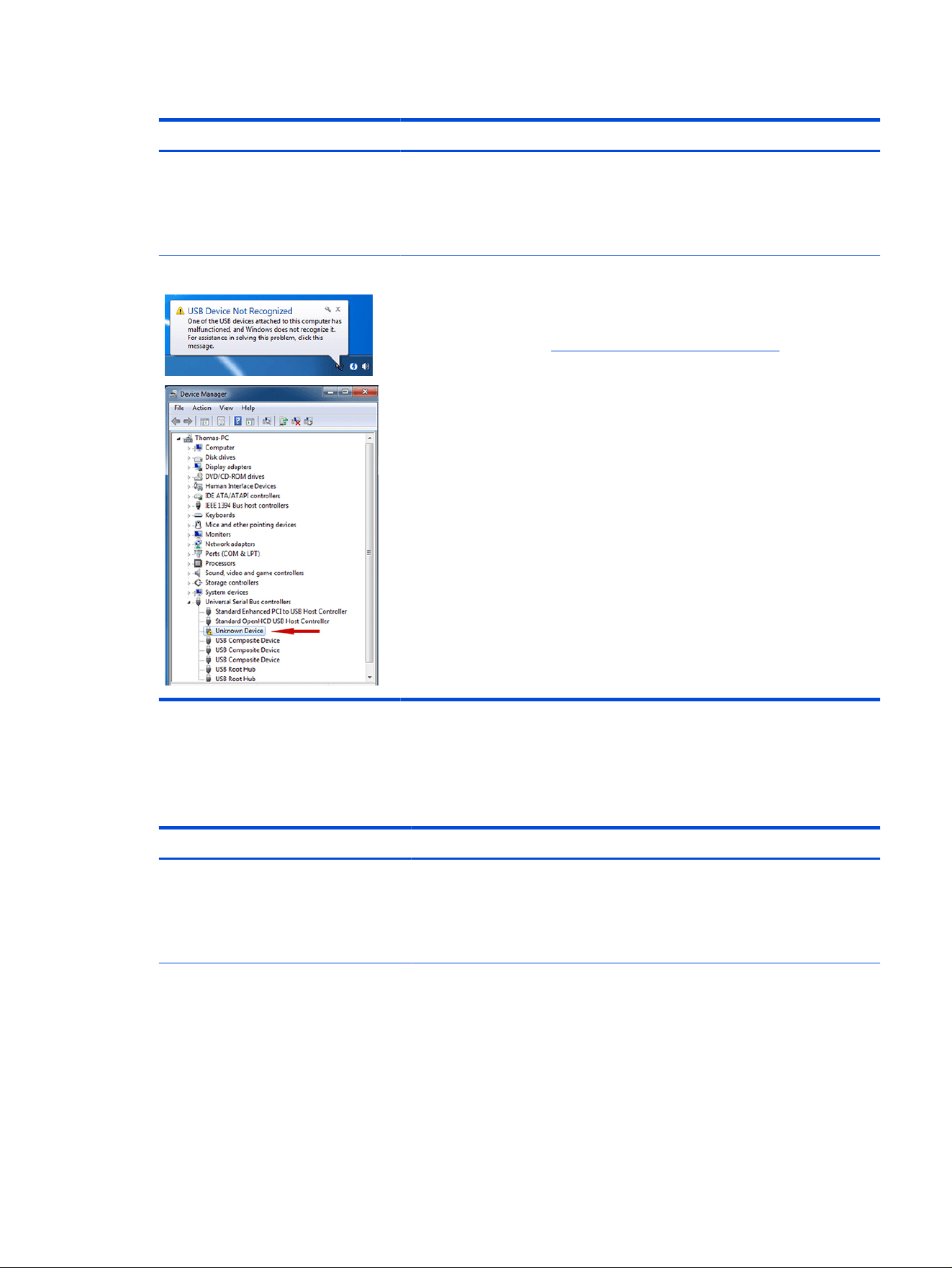
Table 7-42 Issues, possible causes, and xes
Items Procedures
Symptoms
● USB devices are not recognized
● USB devices are not charging
Possible causes
USB devices do not have the latest software drivers, port has insufcient power, or
the devices are not compliant.
NOTE: USB Type-C uses a different connector.
Examples of USB device Not Recognized Troubleshooting steps
1. Unplug the USB device. Restart the computer (wait for 2–5 minutes) to reset the
USB port or hub in case of a power surge.
2. Perform a soft reset (9. Soft reset (Default Settings) on page 76), and verify if the
USB device is recognized.
3. Verify whether the USB device is recognized in Device Manager > Universal
Serial Bus Controller, or the USB is recognized without a yellow warning
symbol, or bang.
4. Verify whether the latest USB driver, USB chipset driver, or both are installed. You
can remove or reinstall the USB driver.
5. Be sure the USB device is supported, for example, USB 3.0 device requires more
power draw (0.9 A) from a USB port than a USB 2.0 device (0.5 A). As a result,
identify the USB charging port to be used for charging a USB device, or an
external AC power adapter might be required for an external USB storage device
to work properly.
6. Test with veried working USB devices (keyboard, mouse, USB key) to be sure
USB ports are functional.
7. Test the USB device on a veried working computer to be sure the USB device is
not malfunctioning.
Smart card reader
Use this information to troubleshoot smart card reader issues.
Table 7-43
Issues, possible causes, and xes
Items Procedures
Symptoms
● Not recognized
● Unable to write
Possible causes
Physical damage, incorrect insertion, dirt, driver, malfunctioning card reader.
NOTE: Some cards have a read-write security switch on the card. Be sure that
switch is set to Write Enabled before attempting to write data to it.
Smart card reader 113
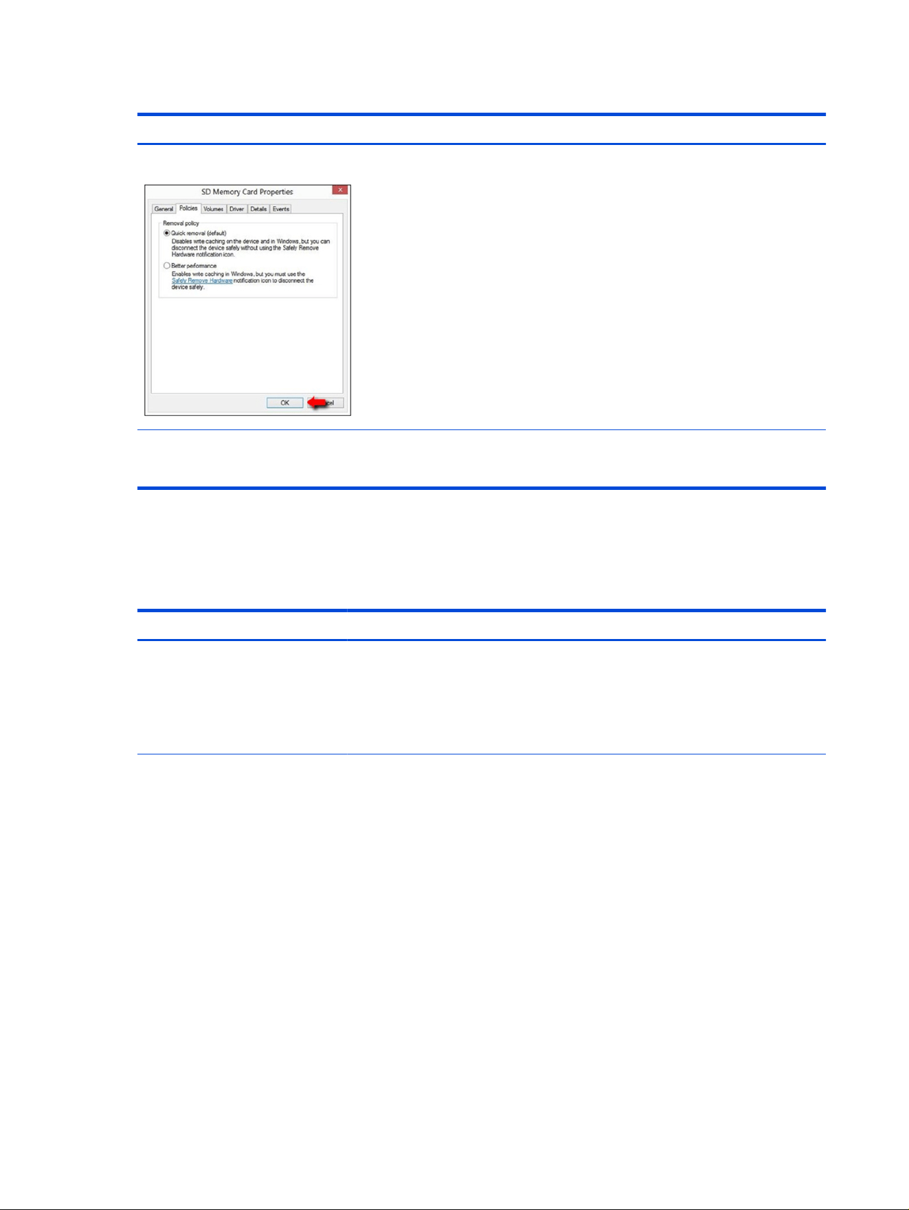
Table 7-43 Issues, possible causes, and xes (continued)
Items Procedures
Card Reader Removal Policy Troubleshooting steps
1. Verify card reader removal policy.
2. Be sure that the card has no physical damage.
3. Inspect the ends of the memory cards for dirt or material closing a hole or
spoiling a metal contact. Clean the contacts with a lint-free cloth and small
amounts of isopropyl alcohol. Replace the memory card if necessary.
4. Reinstall and update the drivers for the card reader.
5. Be sure that the smart card reader is compliant with ISO 7816 Class A, B, and
C.
6. Reinsert the card reader facing the correct way as described in its
documentation.
7. Check reader function with a veried working card.
IMPORTANT:
If the card reader has an in-use indicator light, do not insert or
remove memory cards while the light is ashing. Doing so might cause loss of data
on the card or might permanently damage the card reader.
Speaker, headphone - audio issues
Use this information to troubleshoot audio issues.
Table 7-44
Issues, possible causes, and xes
Items Procedures
Symptoms
● No sound from external or
internal speakers
● Distorted sound, too soft, too
loud, intermittent
Possible causes
Volume turned down, sound card not recognized, malfunctioning hardware, electronic
interference.
114 Chapter 7 Troubleshooting guide

Table 7-44 Issues, possible causes, and xes (continued)
Items Procedures
Troubleshooting steps
1. Remove any device connected to the audio jack to enable the internal speaker.
2. Close all open programs.
3. Perform one of these tasks:
●
Adjust volume by pressing fn + f6 or f7. Be sure that volume button light is not
amber (mute).
● Adjust Windows volume control by selecting the speaker icon on the Windows
taskbar. Be sure that the sound is not muted.
4. Verify that the sound card is detected in Windows Device Manager.
5. Reinstall the latest audio driver.
6. Test audio device using the HP PC Hardware Diagnostics (UEFI) tool (f2 >
Component Tests > Audio).
7. Test with a veried working operating system. If issue is resolved, restore full
operating system.
8. Test with veried working external speakers or headset.
9. Reseat internal speaker connections.
10. Test with veried working internal speakers.
11. Replace internal speakers.
No sound from headphones
1. Perform one of these tasks:
● Adjust volume by pressing fn + f6 or f7. Be sure that volume button light is not
amber (mute).
● Adjust Windows volume control by selecting the speaker icon on the Windows
taskbar. Be sure that the sound is not muted.
2. Check headphone cable connection.
3. Test with a veried working audio board.
4. Replace audio board and verify the change.
No sound from external speakers 1. Verify that external speakers are turned on.
2. Disconnect headphones from headphone jack.
3. Perform one of these tasks:
● Adjust volume by pressing fn + f6 or f7. Be sure that volume button light is not
amber (mute).
●
Adjust Windows volume control by selecting the speaker icon on the Windows
taskbar. Be sure that the sound is not muted.
4. Check for possible interference from devices nearby that might affect the audio (cell
phone or portable communications handset).
Speaker, headphone - audio issues 115
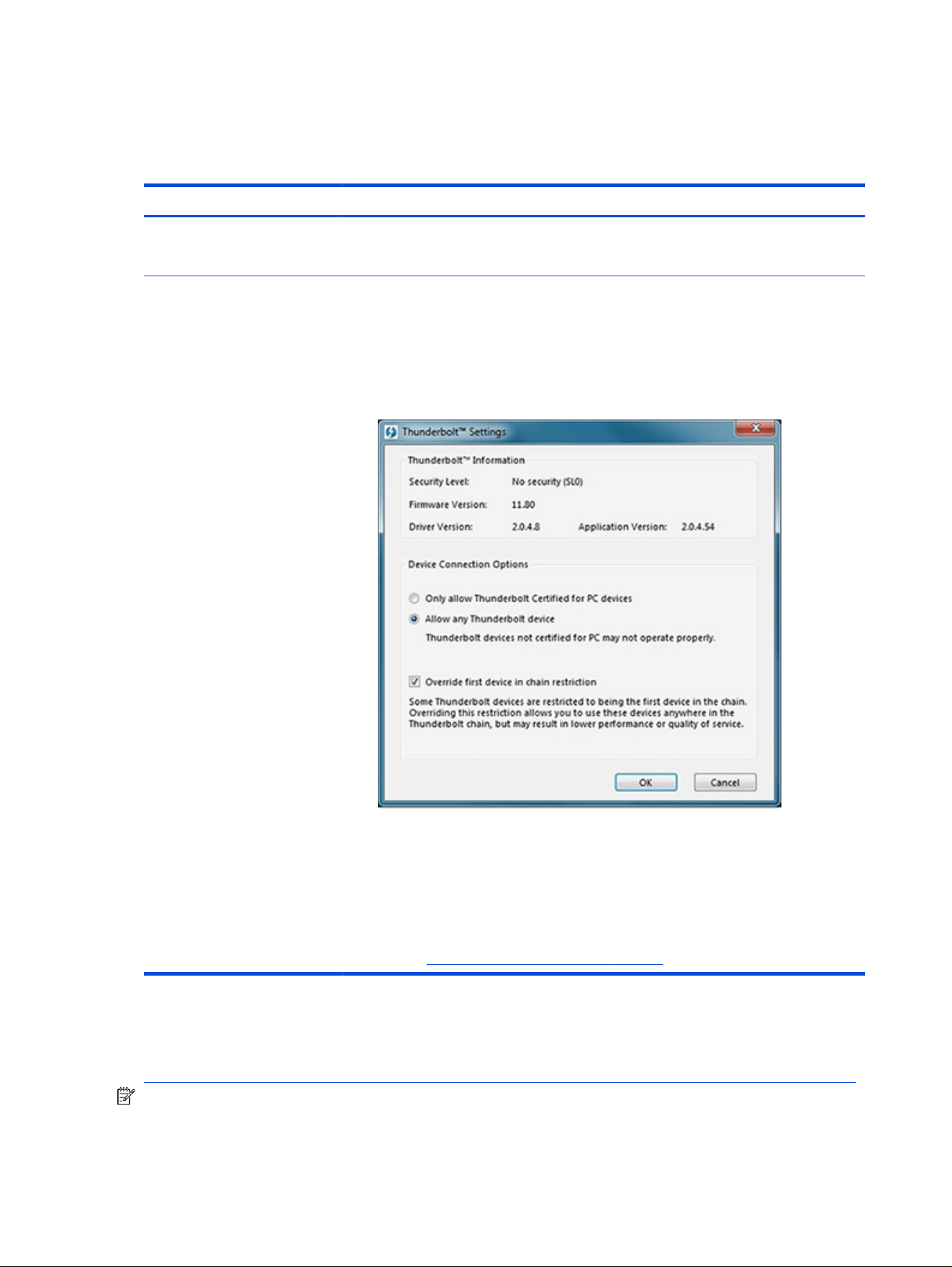
Thunderbolt (TB)
Use this information to troubleshoot Thunderbolt issues.
Table 7-45 Issues, possible causes, and xes
Items Procedures
Symptom
Thunderbolt device not working
Possible causes
BIOS, drivers, and user settings.
Troubleshooting steps
1. Update to the latest BIOS and choose appropriate TB Port settings.
2. Reset User Account Settings to default.
3. Update Intel Thunderbolt software that includes rmware version (for TB controller),
driver version (operating system driver), and application version.
4. Verify that Windows Device Manager detects the TB device.
5. Verify cable connection to TB port.
6. Test with a veried working TB board, if possible.
NOTE: Thunderbolt is new technology. Thunderbolt cable and Thunderbolt device must be
compatible with Windows. To determine whether your device is Thunderbolt Certied for
Windows, see https://thunderbolttechnology.net/products.
Storage
Use this information to troubleshoot storage issues.
NOTE:
● Back up all critical data before troubleshooting the drive.
116
Chapter 7 Troubleshooting guide
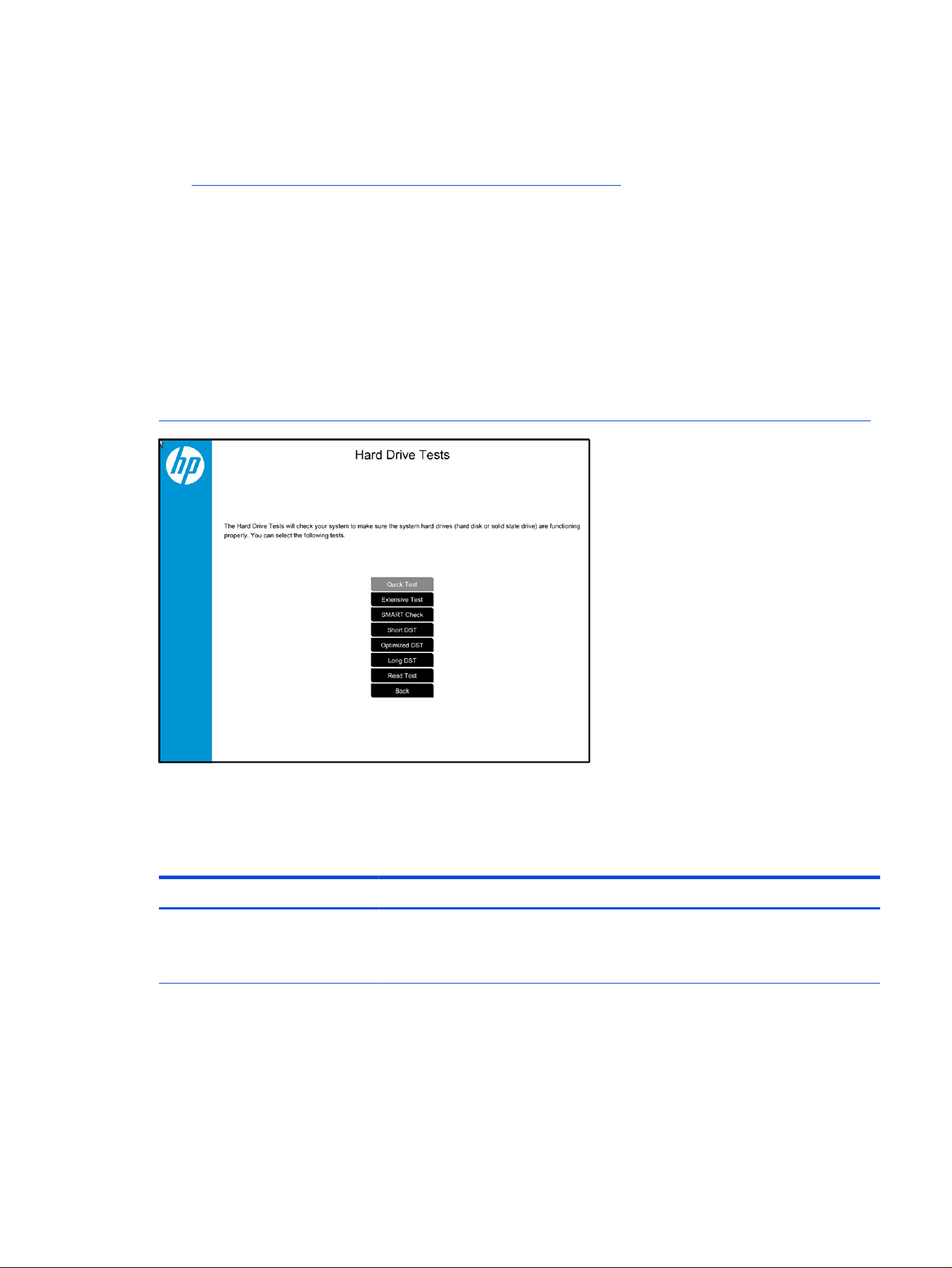
● Before contacting support, HP recommends that you run a drive (HDD, SSD, M.2 drive) test using the
HP PC Hardware Diagnostics (UEFI) tool on the suspected failed drive.
● Diagnose the hard drive using BIOS, Diagnostics built in the shipping image, or an external USB
(https://support.hp.com/us-en/help/hp-pc-hardware-diagnostics).
● HP recommends the Drive Quick Test to quickly (less than 10 minutes) identify the malfunctioning
drive. If the issue still exists, run Extensive Test (more than two hours, or loop mode, which runs until
an error occurs).
● If any test fails, record failure code and contact support for instructions about how to order a
replacement hard drive.
● If all of the tests pass, the hard drive is not damaged. As a rule, HP will not replace a hard drive under
warranty that does not fail the HP Hard Drive Self-Test.
● If there is no physical problem with the hard drive or memory, then try reinstalling the Windows
operating system to troubleshoot the problem.
Hard drive or SSD not recognized
Use this information to troubleshoot storage device issues.
Table 7-46
Issues, possible causes, and xes
Items Procedures
Symptom
Hard drive is not recognized during
POST
Possible causes
Loose connection, faulty hard drive, faulty drive conguration/BIOS setting.
Hard drive or SSD not recognized 117

Table 7-46 Issues, possible causes, and xes (continued)
Items Procedures
Troubleshooting steps
1. Perform a hard reset (8. Hard reset on page 75).
2. Reset BIOS to default.
3. Verify hard drive connection and ex cable. Reseat hard drive and cable connection.
For multiple storage devices, keep the primary drive with the operating system and
remove other devices.
4. Use the HP Hardware Diagnostics tool to verify that the drive is recognized and test
it.
5. If the hard drive fails diagnostics, record failure and have the drive replaced.
6. Identify when the issue is related to software. If the hard drive passes diagnostics,
test the drive on a veried working computer. If the failure follows the drive, reinstall
the operating system to be sure that software is not an issue.
7. Test with a veried working hard drive. If it is still not recognized, the system board is
faulty.
NOTE: If the drive is seen in BIOS and Diagnostics, try a secure erase before replacing a
drive as this might resolve related issues.
No boot to operating system (no read-write error)
Use this information to troubleshoot issues with booting to the operating system.
Table 7-47
Issues, possible causes, and xes
Items Procedures
Symptoms
● POST error message: Boot
Device not found (3F0)
● Hang when booting to operating
system
Possible causes
Operating system, loose connection, faulty hard drive, BIOS conguration, Secure Boot.
Troubleshooting steps
1. Verify whether Secure Boot is enabled in BIOS. Secure Boot prevents legacy boot
devices from starting the computer, including bootable CDs and DVDs.
2. Reset BIOS to default. Be sure that BIOS Boot Mode in Boot Option is set up
properly for bootable device and its operating system (for example, UEFI Native for
an older Windows OS).
Another example, choosing Legacy Boot Order for a UEFI device causes "Boot
Device not found (3F0)" error.
3. Verify hard drive connection and ex cable. Reseat connection. For multiple storage
devices, keep the primary drive with the operating system and remove other devices.
4. Use PC Hardware Diagnostics tool to test. Record failure code and have the hard
drive replaced.
5. If there is no error, reinstall the operating system using HP Restore.
6. Test with a veried working operating system hard drive, if available.
118
Chapter 7 Troubleshooting guide

Table 7-47 Issues, possible causes, and xes (continued)
Items Procedures
Note If there is a hard drive POST error message, see POST error messages and user actions
on page 127.
Read-write error
Use this information to troubleshoot read and write errors.
Table 7-48 Issues, possible causes, and xes
Items Procedures
Symptoms
● POST error message (for
example, error code 301)
● Hang when working on data,
les, documents
Possible causes
Loose connection, faulty hardware.
Troubleshooting steps
1. Perform a hard reset (8. Hard reset on page 75).
2. Reset BIOS to default (9. Soft reset (Default Settings) on page 76).
3. Verify the drive connection and ex cable. Reseat connection (10. Reseat cables and
connections on page 76).
4. Use the HP Hardware Diagnostics tool to test. If failed, record failure code and have
the hard drive replaced.
5. If no error with HP PC Hardware Diagnostics (UEFI) tool, try to repair the hard drive
and its
les in Windows (using command “CHKDSK /f /r /x”). Use HP Restore to
reinstall the operating system, if needed.
6. Test with a veried working hard drive. If it is not recognized, the system board is
faulty.
Note
If there is a hard drive POST error message, see POST error messages and user actions
on page 127.
Slow performance
Use this information to troubleshoot performance issues.
Table 7-49
Issues, possible causes, and xes
Items Procedures
Symptoms
Slow performance even when
performing small read-write
operations
Possible causes
Operating system les, hard drive is full.
Troubleshooting steps
1. Transfer data from the hard drive to create more space. Microsoft recommends at
least 200 MB to sync system les.
2. Perform disk defragmentation to consolidate fragmented data on the hard drive so
that it works more efciently.
NOTE: Do not defragment an SSD.
Read-write error 119

Table 7-49 Issues, possible causes, and xes (continued)
Items Procedures
Tips & tricks For optimal system performance, place your operating system and all of your most
commonly used applications and les on the fastest hard drive (SSD) and fastest areas on
the drive (primary partition of 200 GB max).
See Routine maintenance for performance improvement on page 128.
Blue screen (BSOD) error
A faulty hard drive can cause a blue screen error. Perform the drive tests using the HP Diagnostics Tool to
be sure that the drive is functional.
If all of the tests are successful, see Common blue screen error messages on page 129 for detailed
troubleshooting steps.
Noisy hard drive
Use this information to troubleshoot a noisy hard drive.
IMPORTANT: Because an SSD has no moving parts, it does not make loud or clicking noises.
Depending on type and rotational speed, some hard drives make more noise than others.
Not all noises are related to the fan or hard drive.
Table 7-50
Issues, possible causes, and xes
Items Procedures
Symptoms
● Loud noise from hard drive
● Clicking noise from hard drive
● Still boots to operating system
and operates normally
Possible causes
BIOS, hard drive rmware, driver, faulty drive, power supply (AC adapter).
Troubleshooting steps
1. Update BIOS and hard drive rmware.
2. Examine AC adapter to be sure that it is not faulty or overloaded. Disconnect all
peripherals (USB storage, dock, and others).
3. Remove hard drive to isolate the noise.
4. Test the hard drive on a veried working computer if the noise continues. If the hard
drive makes the same noise or clicking sounds, the sounds are either normal sounds
for the hard drive or a fault with the hard drive.
5. Verify original hard drive connection and ex cable. Reseat hard drive and
connection.
6. Run HP PC Hardware Diagnostics (UEFI). If failed, record failure code and replace
hard drive.
7. If you nd no error with HP PC Hardware Diagnostics (UEFI), perform disk
defragmentation. Some hard drives make a clicking noise when highly fragmented.
120
Chapter 7 Troubleshooting guide

Table 7-50 Issues, possible causes, and xes (continued)
Items Procedures
Tips For optimal system performance, place your operating system and all of your most
commonly used applications and les on the fastest hard drive or SSD and on the fastest
areas on the drive (primary partition of 200 GB max).
See Routine maintenance for performance improvement on page 128.
Mechanical
Use this information to troubleshoot mechanical issues.
Noise (sound)
Use this information to troubleshoot abnormal noise issues.
Table 7-51 Issues, possible causes, and xes
Items Procedures
Symptoms
Computer emits abnormal noise
Possible causes
Aside from basic components (power adapter, supply, fan, speaker, hard drive, optical
drive, display panel, external devices), it is also common for electronic components to
produce noise.
Troubleshooting steps
1. Inspect external power source and change to veried working one.
2. Determine whether the noise comes from AC power adapter. Test with a veried
working AC adapter.
Disconnect external devices and all cables connected to the computer to isolate issue to
computer only.
Noisy fan Determine whether the noise comes from the fan. Disconnect the fan briey to isolate
whether noise originates from fan. If noise is absent with fan disconnected, see Fan runs
constantly on page 122.
Noisy hard drive Determine whether the noise comes from the hard drive.
See Noisy hard drive on page 120.
Noisy optical drive 1. Determine whether the noise comes from an optical drive.
2. Remove CD/DVD from the optical drive.
Noisy speaker 1. Determine whether the noise comes from speaker.
2. Test with a veried working external headset/speaker.
Noisy display Determine whether the noise comes from display panel (humming noise). Change display
frequency settings. See Display on page 101.
The section below is intended for authorized service providers and technicians.
1. After disassembling the chassis, inspect components of the interior for excessive
wear or damage.
2. If noise issues persist, proceed with process of elimination for battery, AC adapter,
or boards.
Mechanical 121

Fan runs constantly
Use this information to troubleshoot a constantly running fan.
Table 7-52 Issues, possible causes, and xes
Items Procedures
Symptoms
● Fan never stops running
● Generates heat
● Decreased computer
performance
Possible causes
● BIOS not up to date.
● Thermal condition (fan, air ow)—fan might not be defective but must run constantly
to remove excess heat generated by electrical components.
● Inappropriate conguration.
Troubleshooting steps
General actions
1. Verify whether BIOS is set to Fan Always on while on AC Power F10 Setup. When
starting the computer, press f10 to open Setup, and then select Advanced > Built-In
Device Options Menu.
2. Update BIOS and drivers (4. Update BIOS and drivers on page 69) and reset BIOS
to default. BIOS can implement new fan characteristics and updates for other
components.
3. Perform a hard reset (8. Hard reset on page 75). Performing a hard reset can reset
recorded thermal values in memory.
Thermal-related issue
1. Verify that fan is spinning. Reseat fan cable before moving to next step.
a. Check fan and connection. Reseat fan cable.
b. Be sure that no obstructions or dust are in heat sink fan, heat sink n, or vent.
c. Test fan using HP PC Hardware Diagnostics (UEFI) tool. Be sure that the fan is
not producing loud noise and that fan blades spin correctly.
d. Test with a veried working fan.
e. Replace the fan.
2. Verify thermal solution
Use the Thermal Monitor tool in HP PC Hardware Diagnostics (UEFI), which is
available only to authorized service providers and technicians, to run a stress test
(processor and GPU) and verify that thermal sensors are within limits after thermal
condition is serviced.
User
conguration
Change Power Options in Windows (for example, choosing Balanced mode instead of
High performance). High performance and extensive graphics might cause the fan to run
constantly to release the heat.
Notes BIOS currently omits fan presence detection to shorten startup time delay to less than
4 seconds. Therefore, the fan error is generated based on previous startup to operating
system that found system fan error.
Fan often is part of thermal solution, including heat sink, heat sink n/mufer, and thermal
grease. Fan replacement requires restart and fan function verication using HP PC
Hardware Diagnostics (UEFI) tool.
122 Chapter 7 Troubleshooting guide

Thermal shutdown (hot)
Use this information to troubleshoot a thermal shutdown.
Table 7-53 Issues, possible causes, and xes
Items Procedures
Symptoms
Similar to fan runs constantly issue
(Fan runs constantly on page 122)
● System shutdown
● Abnormal heat
● Continually running fan
● Decreased computer
performance
Possible causes
BIOS not up to date, thermal condition (fan, air ow)
Troubleshooting steps
1. Update BIOS and drivers (4. Update BIOS and drivers on page 69) and reset BIOS
to default. BIOS can implement new fan characteristics and updates for other
components.
2. Perform a hard reset (8. Hard reset on page 75). Performing a hard reset can reset
recorded thermal values in memory.
3. Determine whether you are using a correct AC adapter.
4. Be sure to turn power off completely when putting a notebook in a travel bag.
Thermal-related issue
1. Verify thermal condition:
a. Check fan and connection. Check if fan is spinning when computer is on. Reseat
fan cable.
b. Be sure that no obstructions or dust are in heat sink fan, n, or vent.
c. Be sure that the notebook is not sitting on a hot surface that blocks vent intakes.
d. Test fan using HP PC Hardware Diagnostics UEFI tool. Be sure that the fan is not
producing a loud noise and that fan blades spin correctly.
e. Test with a veried working fan.
f. Remove old thermal compound and pads, and replace properly with new pads.
2. Verify thermal solution:
Use Thermal Monitor tool (available only to authorized service providers and
technicians) to run stress test (processor and GPU), and verify that thermal sensors
are within limits after thermal condition is serviced.
Additional information
The following sections provide additional information that you can use during the troubleshooting process.
Thermal shutdown (hot)
123

Acronyms
These acronyms are used in this chapter.
Blue screen (BSOD): A Windows error screen that can occur if a problem causes your computer to shut
down or restart unexpectedly.
When you experience this type of error, you cannot see items such as the Start menu or the taskbar when
your computer is turned on. Instead you might see a blue screen with a message that your computer ran
into a problem and needs to restart.
CPU: Central processing unit
DIMM: Dual in-line memory module
Daughterboard: Type of circuit board that plugs into or is attached to the system board or similar
expansion card to extend its features and services
GPU: Graphics processor unit
GTS: General troubleshooting step
HDD: Hard drive
KB: Keyboard
LVDS: Low-Voltage Differential Signaling
MSG: Maintenance and Service Guide
mWS: Mobile workstations
OS: Operating system
PC: Personal computer
POST: Power-On Self-Test
SSD: Solid-state drive
TSG: Troubleshooting Guide
UEFI: Unied Extensible Firmware Interface
WLAN: Wireless local area network
WS: Workstations
WWAN: Wireless wide area network
Blinking lights and startup error codes
In some cases, when the host processor is not executing code or does not have the necessary code to
drive the display, light blink codes inform you of a problem.
Table 7-54
Blinking lights and boot error codes
Blink codes Error
Amber battery light: blinks 1 Hz continuously Embedded Controller unable to load rmware
124 Chapter 7 Troubleshooting guide

Table 7-54 Blinking lights and boot error codes (continued)
Blink codes Error
Caps and num lock lights = 1 blink Processor not executing code
Caps and num lock lights = 2 blinks BIOS recovery code unable to nd valid BIOS recovery image
Caps and num lock lights = 3 blinks Memory module error
Caps and num lock lights = 4 blinks Graphics controller error
Caps and num lock lights = 5 blinks System board error
Caps and num lock lights = 6 blinks Intel Trusted Execution Technology (TXT) Error
Caps and num lock lights = 7 blinks Sure Start unable to nd valid BIOS Boot Block image
Caps and num lock lights = 8 blinks Sure Start has identied a problem (Manual Recovery Policy
Set)
Processor not executing code
This computer experienced a problem due to the failure of certain code to execute, resulting in a failed
startup of the processor.
The issue could be related to the processor or the system board in the computer. If the processor is
socketed, be sure that the processor is seated correctly in the socket. If this error reoccurs, see General
troubleshooting steps on page 65.
NOTE: The computer attempts to notify you of this problem through a series of blinking lights. When
you attempt to turn on the computer from an Off or Hibernated state, lights associated with the caps lock
and num lk keys both blink once, followed by a pause, and then continue in a repeating pattern.
BIOS recovery code unable to
nd valid BIOS recovery image
This computer has experienced a problem in locating a valid BIOS image, resulting in a failed startup.
You can resolve this problem by placing a clean copy of the system BIOS on a USB key or in
the appropriate hard drive directory and performing a restart. If this error reoccurs, see General
troubleshooting steps on page 65.
NOTE: The computer attempts to notify you of this problem through a series of blinking lights. When
you attempt to turn on the computer from an Off or Hibernated state, lights associated with the caps lock
and num lock keys both blink twice, followed by a pause, and then continue in a repeating pattern.
Memory module error
This computer has experienced a memory initialization problem resulting in a failed startup. This issue
might be related to the memory modules in the computer. You can resolve this problem by ensuring that
memory modules are correctly inserted and seated.
If this error reoccurs, you must use a service event to determine the source of the error (memory modules
or system board) and take the appropriate corrective action.
NOTE: The computer attempts to notify you of this problem through a series of blinking lights. When
you attempt to turn on the computer from an Off or Hibernated state, lights associated with the caps lock
and num lock keys both blink three times, followed by a pause, and then continue in a repeating pattern.
Processor not executing code
125

Graphics Controller Error (No Controller)
This computer has experienced a graphics controller initialization problem resulting in a failed startup. This
issue might be related to the graphics controller in your machine.
You can resolve this problem by ensuring that the graphics controller module is seated correctly in
machines with modular graphics. If this error reoccurs, you must use a service event to identify the source
of the error and take the appropriate corrective action.
NOTE: The computer attempts to notify you of this problem through a series of blinking lights. When
you attempt to turn on the computer from an Off or Hibernated state, lights associated with the caps lock
and num lock keys both blink four times, followed by a pause, and then continue in a repeating pattern.
Failure System Board Error
This computer has experienced a system board initialization problem resulting in a failed startup. This
issue might be related to the system board in the computer. You must use a service event to identify the
source of the error and take the appropriate corrective action.
NOTE: The computer attempts to notify you of this problem through a series of blinking lights. When
you attempt to turn on the computer from an Off or Hibernated state, lights associated with the caps lock
and num lock keys both blink ve times, followed by a pause, and then continue in a repeating pattern.
Intel Trusted Execution Technology (TXT) Error
This computer has experienced a problem related to the Intel Trusted Execution Technology resulting in a
failed startup. The error occurs when three situations are true:
● The Intel Trusted Execution Technology (TXT) has been enabled on the computer.
● Policies have been set to prevent startup if the BIOS measurement has changed.
● The BIOS measurement has changed.
For more information about Intel TXT, go to Intel Trusted Execution Technology .
You must use a service event to resolve this issue.
NOTE: The computer attempts to notify you of this problem through a series of blinking lights. When
you attempt to turn on the computer from an Off or Hibernated state, lights associated with the caps lock
and num lock keys both blink six times, followed by a pause, and then continue in a repeating pattern.
Sure Start unable to
nd valid BIOS Boot Block image
This computer has experienced a problem in locating a valid BIOS image, resulting in a failed startup. You
must use a service event to identify the source of the error and take appropriate corrective action.
NOTE: The computer attempts to notify you of this problem through a series of blinking lights. When
you attempt to turn on the computer from an Off or Hibernated state, lights associated with the caps lock
and num lock keys both blink seven times, followed by a pause, and then continue in a repeating pattern.
Sure Start has
identied a problem (Manual Recovery Policy Set)
This computer has experienced a problem in locating a valid BIOS image, resulting in a failed startup.
HP Sure Start normally repairs this type of issue; however, on this computer HP Sure Start has been
congured to operate in manual mode key sequence.
126
Chapter 7 Troubleshooting guide

To proceed with the repair, press and hold the following keys: esc + up arrow + down arrow. To avoid
the need for this manual recovery step, set the HP Sure Start recovery policy to automatic. If this error
reoccurs, you must use a service event to identify the source of the error and take appropriate corrective
action.
NOTE: The computer attempts to notify you of this problem through a series of blinking lights. When
you attempt to turn on the computer from an Off or Hibernated state, lights associated with the caps lock
and num lk keys both blink eight times, followed by a pause, and then continue in a repeating pattern.
POST error messages and user actions
Use this information to determine the meaning of POST error messages.
Table 7-55 POST error messages and user actions to address the error
Test description Failure descriptions Error
code
Possible user actions
Product
information
Invalid value 00A Contact support for assistance.
Startup test Memory module 200 Attempt to reseat the memory module and then repeat the test.
Search http://www.hp.com/support for details about troubleshooting
issues related to the memory module.
If the memory module still fails, contact support.
Startup test Hard Disk 1 SMART 301 Attempt to reseat the hard drive and repeat the test.
The hard disk drive might have failed. Contact support for assistance.
Startup test Hard Disk 2 SMART 302 The hard drive might have failed. Contact support for assistance.
Startup test Hard Disk 1 Quick 303 The hard drive might have failed. Contact support for assistance.
Startup test Hard Disk 2 Quick 304 The hard drive might have failed. Contact support for assistance.
Run-in test Memory module 200 Attempt to reseat the memory module and then repeat the test.
Search http://www.hp.com/support for details about troubleshooting
issues related to the memory module.
If the memory module still fails, contact support.
Run-in test Hard Disk 1 SMART 301 Attempt to reseat the hard drive and repeat the test.
The hard drive might have failed. Contact support for assistance.
Run-in test Hard Disk 2 SMART 302 The hard drive might have failed. Contact support for assistance.
Run-in test Hard Disk 1 Quick 303 The hard drive might have failed. Contact support for assistance.
Run-in test Hard Disk 2 Quick 304 The hard drive might have failed. Contact support for assistance.
Hard Disk Test Hard Disk 1 SMART 301 Attempt to reseat the hard drive and repeat the test.
The hard drive might have failed. Contact support for assistance.
Hard Disk Test Hard Disk 2 SMART 302 The hard drive might have failed. Contact support for assistance.
Hard Disk Test Hard Disk 1 Quick 303 The hard drive might have failed. Contact support for assistance.
Hard Disk Test Hard Disk 2 Quick 304 The hard drive might have failed. Contact support for assistance.
Hard Disk Test Hard Disk 1 Full 305 The hard drive might have failed. Contact support for assistance.
POST error messages and user actions 127

Table 7-55 POST error messages and user actions to address the error (continued)
Test description Failure descriptions Error
code
Possible user actions
Hard Disk Test Hard Disk 2 Full 306 The hard drive might have failed. Contact support for assistance.
Boot Device
Manager
Boot device not
found
3F0 This code indicates a potential problem with the hard drive. Run the
hard drive test.
Boot Device
Manager
Hard Disk 1 Error 3F1 This code indicates a potential problem with the hard drive. Run the
hard drive test.
Boot Device
Manager
Hard Disk 2 Error 3F2 This code indicates a potential problem with the hard drive. Run the
hard drive test.
Boot Device
Manager
Hard Disk 1 SMART 301 This code indicates a potential problem with the hard drive. Run the
hard drive test.
Boot Device
Manager
Hard Disk 2 SMART 302 This code indicates a potential problem with the hard drive. Run the
hard drive test.
BIOS Recovery BIOS Recovery
Occurred
500 This message indicates that BIOS recovery was completed
successfully. No further action is required.
BIOS Application BIOS Application
Error
501 The BIOS installation might have become corrupted. Download the
latest version of the BIOS and install it. See 4. Update BIOS and drivers
on page 69 for more information.
If reinstalling the BIOS fails, contact support for further assistance.
CMOS Recovery CMOS Recovery
Occurred
502 This message indicates that CMOS recovery was completed
successfully. No further action is required.
Battery Check Primary Battery
Replace
601 This code indicates that the primary battery has very low capacity.
Search http://www.hp.com/support for details about using the HP
Support Assistant to verify the battery capacity and, if necessary, order
a replacement.
Battery Check Secondary Battery
Replace
602 This code indicates that the secondary battery has very low capacity.
Search http://www.hp.com/support for details about using the HP
Support Assistant to verify the battery capacity and, if necessary, order
a replacement.
Wireless Module Not installed or
responding
701 Reseat the wireless LAN adapter module, if your notebook supports it.
Seating or reseating a wireless LAN adapter is unique to each
computer model.
Fan Fan not operating
correctly
90B The system fan might be malfunctioning.
A hard reset can sometimes restore the system fan to working order.
If the system fan continues to malfunction, contact support.
Routine maintenance for performance improvement
The table presents a summary of the suggested times for performing the routine maintenance tasks that
are described in this document.
Table 7-56
Routine maintenance tasks to improve performance
Tasks Weekly Monthly Occasionally
Perform a system tuneup. X
128 Chapter 7 Troubleshooting guide
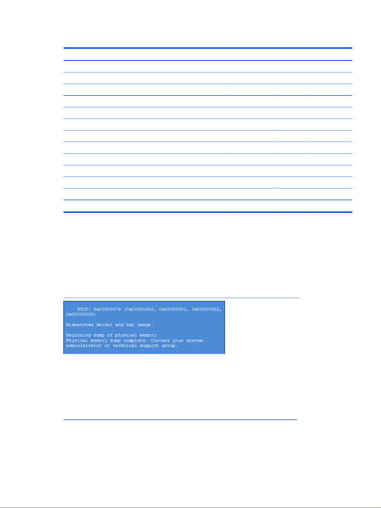
Table 7-56 Routine maintenance tasks to improve performance (continued)
Tasks Weekly Monthly Occasionally
Run Windows Update. X
Scan for and remove viruses. X
Scan for and remove spyware and adware. X
Empty the Recycle Bin. X
Delete temporary internet les. X
Back up user les. X
Create a restore point. X
Defragment the hard drive. X
Run Scan Disk. X
Clean the exterior of the computer. X
Close programs that are not being used. X
Prevent programs from loading at startup. X
Remove rear cover and clean fan blades and vents with compressed air. X
Common blue screen error messages
The following sections dene blue screen error messages.
Error message list
For an example of a Bug Check Code Reference, use this image.
For more information, see
https://msdn.microsoft.com/en-us/library/windows/hardware/hh994433(v=vs.85).aspx.
Note that the hexadecimal number following the word STOP is called the bug check code or Stop code.
Bug check symbolic names
Each bug check code also has an associated symbolic name.
In the example, the screen shows
https://msdn.microsoft.com/en-us/library/windows/hardware/ff559209(v=vs.85).aspx
Microsoft general troubleshooting of Windows bug check codes
Use this information to troubleshoot Windows bug codes.
Common blue screen error messages
129

● If you recently added hardware to the system, try removing or replacing it. You can also check with the
manufacturer to see if any patches are available.
● Try running HP PC Hardware Diagnostics UEFI.
● Check with the manufacturer to see if an updated system BIOS or rmware is available.
● Be sure that any expansion board is properly seated and all cables are completely connected.
● Conrm that any new hardware that is installed is compatible with the installed version of Windows.
● If new device drivers or system services have been added recently, try removing or updating them.
NOTE: Use safe mode when removing or disabling components. Safe mode loads only the
minimum required drivers and system services during the Windows startup. To enter safe mode,
restart your computer and press f8 at the menu that displays the operating system choices. At the
resulting Windows Advanced Options menu, choose Safe Mode.
● Run a virus detection program. Viruses can infect all types of hard drives formatted for Windows, and
resulting drive corruption can generate system bug check codes. Be sure that the virus detection
program checks the Master Boot Record for infections.
● Verify that the system has the latest service pack installed.
● Disable BIOS memory options such as caching or shadowing.
● Check the System Log and Application Log in Event Viewer to see if any additional error messages
have been logged recently. These might pinpoint the cause of the error.
Use Windows Debugging Tool
Debugging Tools for Windows are the primary tools used by Microsoft software developers to analyze and
resolve errors that result in memory dumps.
Use the tool (https://msdn.microsoft.com/library/windows/hardware/ff551063%20(v=vs.85).aspx) to
determine the cause of the error. Follow general steps for downloading, setting up, and using the Windows
10 debugging tool.
NOTE: The following screenshots provide only an example of the tool. Specics shown are not
representative of all applications of the debugging tool. This is a Microsoft tool supported by Microsoft.
Windows Software Development Kit (SDK)
Use these steps to download and use the Windows SDK.
1. Download the SDK from the following link:
https://dev.windows.com/en-US/downloads/windows-10-sdk
130
Chapter 7 Troubleshooting guide
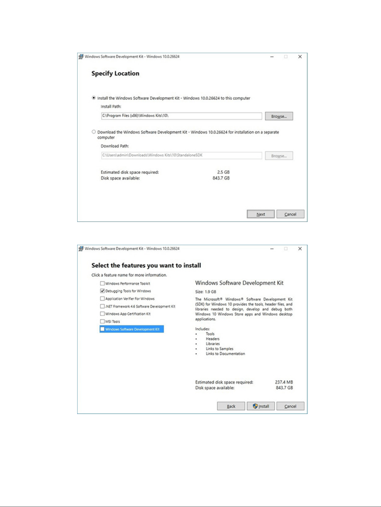
2. Set up the SDK in the conguration window (Windows 10 shown).
3. Select features to install.
Windows Software Development Kit (SDK)
131
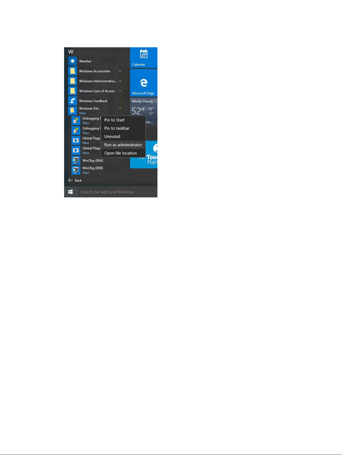
4. Run the SDK as an administrator.
5. Set the symbol path. Select File > Symbol File Path.
● In the Symbol path box,
type SRV*C:\Windows\symbol_cache*http://msdl.microsoft.com/download/
symbols.
● Save the workspace.
132
Chapter 7 Troubleshooting guide
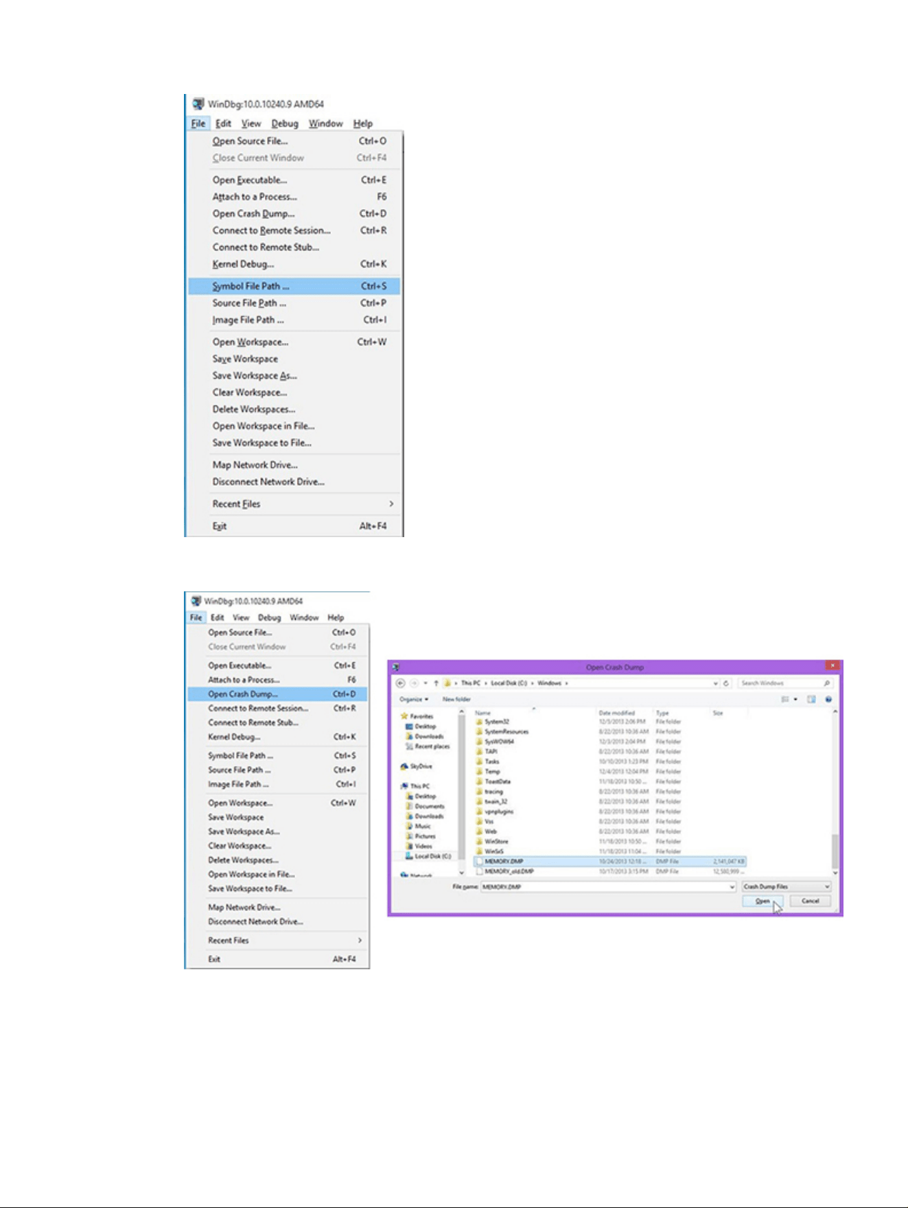
6. Open the crash dump le.
7. Analyze the le. In the following memory dump sample, look for Bug Check 0x3B. The ATIKMAG driver
needs to be investigated for further root cause.
Lookup for Bug Check 0xC2.
Windows Software Development Kit (SDK)
133
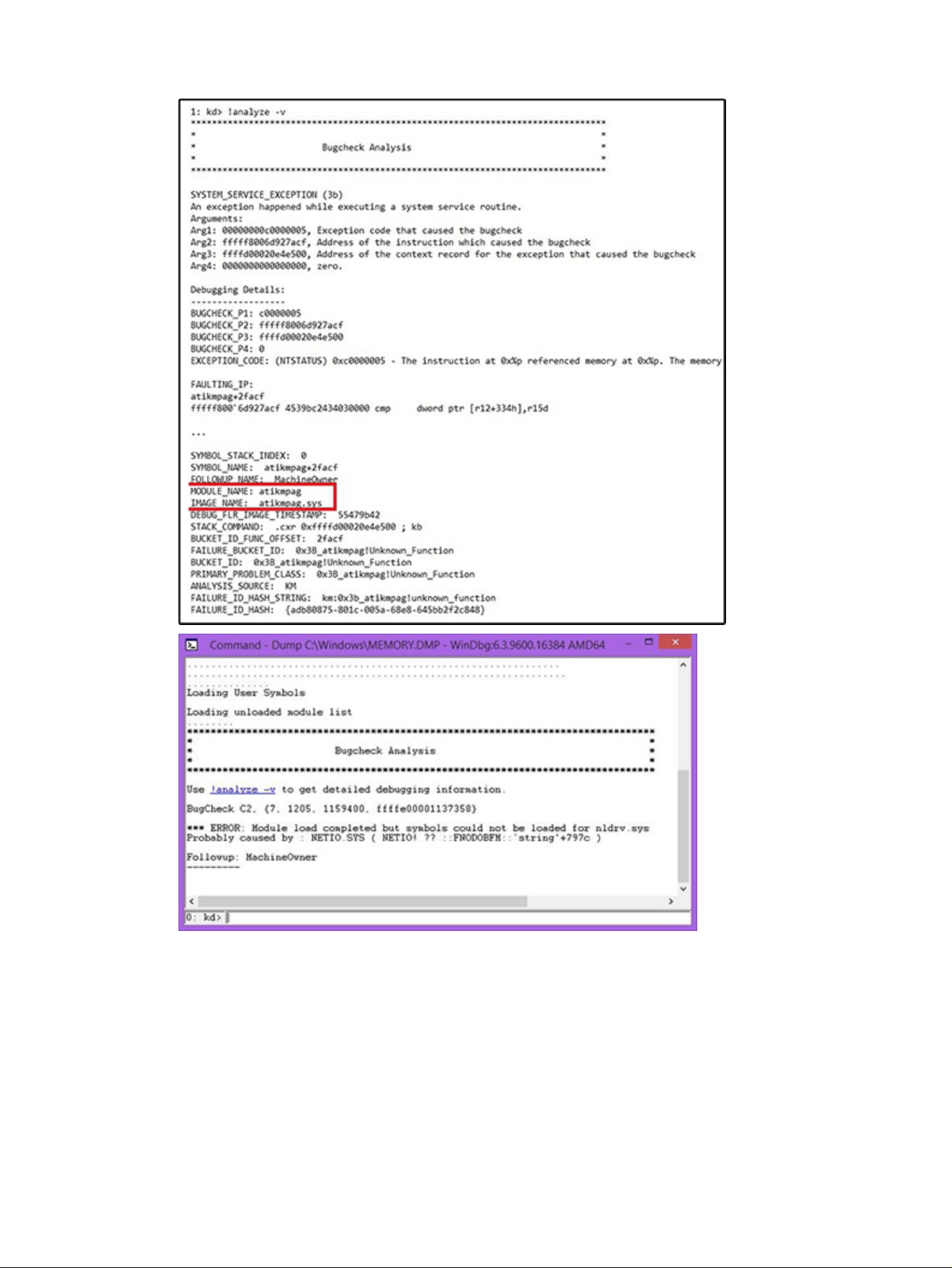
Display issue: pixel anomalies
All HP notebook displays adhere to strict quality and reliability specications. A small percentage of
display panels might have minor cosmetic manufacturing anomalies or irregularities such as bright or
dark dots in the viewable area. These cosmetic imperfections are common to all display panel types, not
specically HP products.
All display panel defects should be examined at the highest possible resolution using both the brightest
and darkest possible backgrounds, because some subpixel failures might not be readily visible under
certain conditions.
134
Chapter 7 Troubleshooting guide

● Type 1: Bright dot on a dark background = Always On
● Type 2: Dark dot on a bright background = Always Off
● Combination = in any combination and any color that are always on or off
Use the HP PC Hardware Diagnostics (UEFI) tool to determine numbers of pixels and their distance. HP
uses the following set of criteria when damaged displays are submitted for warranty coverage.
Table 7-57 Electrical defect criteria
Panel resolution Accept Reject
Subpixel faults
VGA, SVGA, SD, WSVGA, XGA, 720p, SD+, WXGA, HD N ≤ 2 Type 1
N ≤ 2 Type 2
N ≥ 3 Type 1
WXGA+, SXGA+, HD+, SXGA+ N ≤ 3 Type 1
N ≤ 3 Type 2
N ≥ 4 Type 1
WSXGA+, UXGA, FHD, WUXGA N ≤ 4 Type 1
N ≤ 4 Type 2
N ≥ 5 Type 1
QHD, QHD+, WQXGA, UD N ≤ 5 Type 1
N ≤ 5 Type 2
N ≥ 6 Type 1
Electrical defect clusters (defects within a 5 × 5 pixel block)
Minimum distance between ANY allowable defects (unless otherwise specied) S ≥ 25 mm S < 25 mm
Cluster with two or more subpixels with subpixel faults Not allowed
Dim lines Not allowed
Cross lines on/off Not allowed
Horizontal lines on/off Not allowed
Vertical lines on/off Not allowed
NOTE: Examine all LCD panel defects at the highest possible resolution using both the brightest and
darkest possible backgrounds, because some subpixel failures might not be readily visible under certain
conditions.
NOTE: Contact support for assistance if issues are not listed.
Cable management
Proper routing of the internal cables is critical to the operation of the computer. Follow good cable
management practices when you have to remove and install components.
● Handle cables with care to avoid damage.
● Apply only the tension required to seat or unseat cables during insertion or removal from the
connector.
● When possible, handle cables by the connector or pull-strap.
Cable management
135
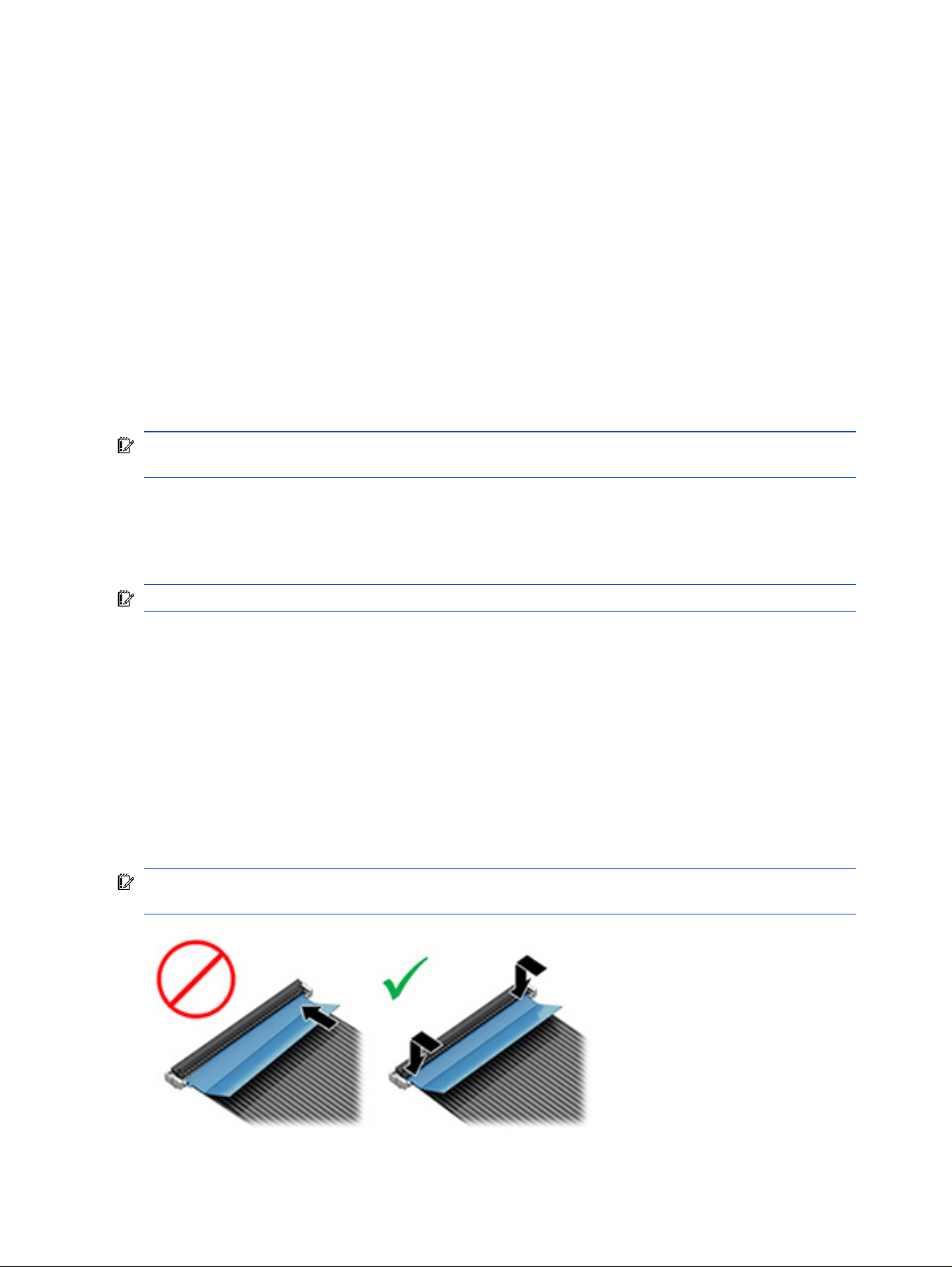
● Route cables in such a way that they cannot be caught or snagged by parts being removed or
replaced.
● Keep cables away from direct contact with major heat sources, such as the heat sink. Some air ow
guides have a cable guide that lets you route cables safely around the heat sink.
● Do not jam cables on top of daughterboards or memory modules (DIMMs). Circuit cards and DIMMs
are not designed to take excessive pressure.
● Keep cables clear of any movable or rotating parts (such as a fan) to prevent them from being cut or
crimped when the component is lowered into its normal position.
● In all cases, avoid bending or twisting the cables. Do not bend any cable sharply. A sharp bend can
break the internal wires.
● Do not rely on components like the keyboard or service door to push cables down internally. Always
position the cables to lie properly by themselves or in the cable guides and chassis areas designed for
cable routing.
IMPORTANT: Always release the connector latch before removing the cable. Otherwise, pulling the
cable could damage the cable pins and result in a failed device.
Connector types
There are several types of connectors on the system board with different requirements for cable removal
or insertion.
IMPORTANT: Do not touch connector pins and connector gold ngers directly with bare hands.
Flex cable
Use this information to properly use ex cables.
When connecting ex cables to a ZIF connector, rotate the latch to 90°, push the cable completely, evenly
into the connector, and then close the latch.
When removing ex cables from a ZIF connector on the system board, you must release the latch before
removing the cable. Always follow these steps:
1. Flip the connector latch 90° to release the cable.
2. Grasp the cable end of the connector and pull it straight out.
IMPORTANT: Always release the connector latch before removing the cable. Otherwise, pulling the
cable could damage the cable pins and result in a failed device.
136
Chapter 7 Troubleshooting guide
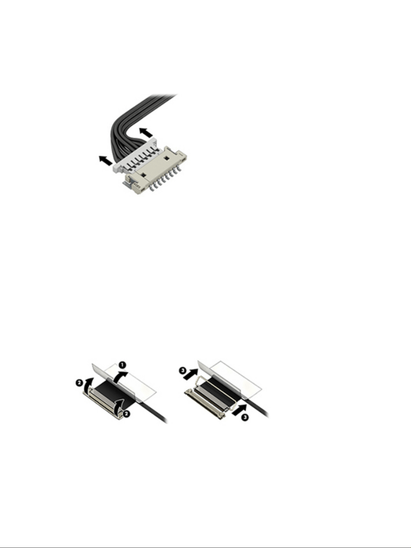
Horizontal cable insertion
Use a at tool to pull the connector evenly. Do not pull on cable to remove.
Slide connector into receptacle on same horizontal plane as board and use a at tool to push evenly into
receptacle.
Multiple-pin horizontal connector (LVDS cable to display panel)
Use these procedures to properly insert and remove a multiple-pin horizontal connector.
Insert procedure:
1. Slide connector evenly into receptacle on same horizontal plane as PCB connector.
2. Pull lock bar to insert and push both sides of connector horizontally to rmly lock.
3. Tape down lock bar over the panel to hold in position.
Reverse the previous procedure to remove the connector:
1. Remove tape.
2. Pull up bar (pull tape) and release the lock with the PCB connector.
3. Pull to the direction in parallel with PCB to withdraw the connector.
Multiple-pin vertical connector (LVDS cable to system board)
Use this procedure to properly insert and remove a multiple-pin vertical connector.
● Remove the connector gasket before removing the connector.
Horizontal cable insertion
137
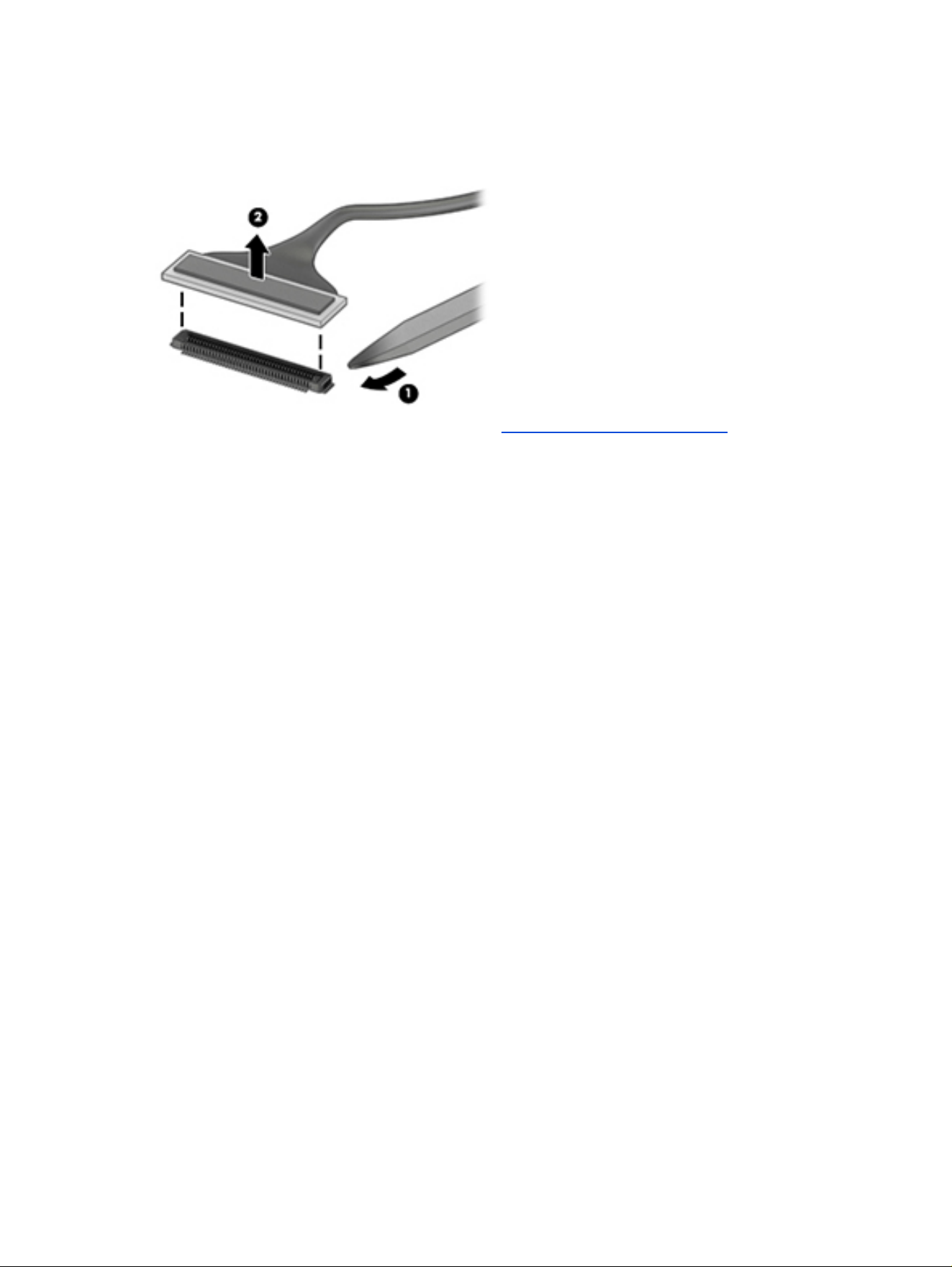
● If the connector has a plastic pull tab, pull the tab to disconnect. Otherwise, use a at tool under the
connector to remove evenly. Do not pull on the cable to remove.
● Press evenly when reseating, reconnecting, or installing the connector.
For more information about cable management, see Cable management on page 135.
138
Chapter 7 Troubleshooting guide

Using Setup Utility (BIOS)8
Setup Utility, or Basic Input/Output System (BIOS), controls communication between all the input and
output devices on the system (such as disk drives, display, keyboard, mouse, and printer). Setup Utility
(BIOS) includes settings for the types of devices installed, the startup sequence of the computer, and the
amount of system and extended memory.
NOTE: To start Setup Utility on convertible computers, your computer must be in notebook mode and
you must use the keyboard attached to your notebook.
Starting Setup Utility (BIOS)
You have several ways to access the Setup Utility (BIOS).
IMPORTANT: Use extreme care when making changes in Setup Utility (BIOS). Errors can prevent the
computer from operating properly.
Use one of these options:
● Turn on or restart the computer and quickly press f10.
● Turn on or restart the computer, quickly press esc, and then press f10 when the Start menu is
displayed.
Updating Setup Utility (BIOS)
Updated versions of Setup Utility (BIOS) might be available on the HP website. Most BIOS updates on the
HP website are packaged in compressed les called SoftPaqs. Some download packages contain a le
named Readme.txt, which contains information regarding installing and troubleshooting the le.
Determining the BIOS version
To decide whether you need to update Setup Utility (BIOS), rst determine the BIOS version on your
computer.
To reveal the BIOS version information (also known as ROM date and System BIOS), use one of these
options.
● HP Support Assistant
1. Perform one of these tasks:
– Select the Search icon in the taskbar, type support in the search box, and then select the
HP Support Assistant app.
– Select the question mark icon in the taskbar.
2. Under My notebook, select Specications.
● Setup Utility (BIOS)
Using Setup Utility (BIOS)
139

1. Start Setup Utility (BIOS) (see Starting Setup Utility (BIOS) on page 139).
2. Select Main, and then make note of the BIOS version.
3. Select Exit, select one of the options, and then follow the on-screen instructions.
● In Windows, press ctrl+alt+s.
To check for later BIOS versions, see Preparing for a BIOS update on page 140.
Preparing for a BIOS update
Be sure to follow all prerequisites before downloading and installing a BIOS update.
IMPORTANT: To reduce the risk of damage to the computer or an unsuccessful installation, download
and install a BIOS update only when the computer is connected to reliable external power using the HP
AC adapter provided with the computer (select products only), a replacement AC adapter provided by HP,
or an AC adapter with the power rating specied on the product label. Do not download or install a BIOS
update while the computer is running on battery power, docked in an optional docking device, or
connected to an optional power source. During the download and installation, follow these instructions:
● Do not disconnect power from the computer by unplugging the power cord from the AC outlet.
● Do not shut down the computer or initiate Sleep.
● Do not insert, remove, connect, or disconnect any device, cable, or cord.
NOTE: If your computer is connected to a network, consult the network administrator before installing
any software updates, especially system BIOS updates.
Downloading a BIOS update
After you review the prerequisites, you can check for and download BIOS updates.
1. Perform one of these tasks:
● Select the Search icon in the taskbar, type support in the search box, and then select the HP
Support Assistant app.
● Select the question mark icon in the taskbar.
2. Select Updates. The Checking for Updates window opens, and Windows checks for updates.
3. Follow the on-screen instructions.
4. At the download area, follow these steps:
a. Identify the most recent BIOS update and compare it to the BIOS version currently installed on
your computer. If the update is more recent than your BIOS version, make a note of the date,
name, or other identier. You might need this information to locate the update later, after it has
been downloaded to your hard drive.
b. Follow the on-screen instructions to download your selection to the hard drive.
Make a note of the path to the location on your hard drive where the BIOS update is downloaded.
You will need to access this path when you are ready to install the update.
140
Chapter 8 Using Setup Utility (BIOS)

Installing a BIOS update
BIOS installation procedures vary. Follow any instructions that appear on the screen after the download is
complete. If no instructions appear, follow these steps.
1. Select the Search icon in the taskbar, type file in the search box, and then select File Explorer.
2. Select your hard drive designation. The hard drive designation is typically Local Disk (C:).
3. Using the hard drive path you recorded earlier, open the folder that contains the update.
4. Double-click the le that has an .exe extension (for example, lename.exe).
The BIOS installation begins.
5. Complete the installation by following the on-screen instructions.
NOTE: After a message on the screen reports a successful installation, you can delete the downloaded
le from your hard drive.
Installing a BIOS update
141

Computer Setup (BIOS), TPM, and HP
Sure Start
9
HP provides several tools to help set up and protect your computer.
Using Computer Setup
Computer Setup, or Basic Input/Output System (BIOS), controls communication between all the input and
output devices on the system (such as hard drives, display, keyboard, mouse, and printer). Computer Setup
includes settings for types of devices installed, the startup sequence of the computer, and amount of
system and extended memory.
NOTE: Use extreme care when making changes in Computer Setup. Errors can prevent the computer
from operating properly.
To start Computer Setup, turn on or restart the computer, and when the HP logo appears, press f10 to
enter Computer Setup.
Navigating and selecting in Computer Setup
You can navigate and select in Computer Setup using one or more methods.
● To select a menu or a menu item, use the tab key and the keyboard arrow keys and then press enter, or
use a pointing device to select the item.
● To scroll up and down, select the up arrow or the down arrow in the upper-right corner of the screen, or
use the up arrow key or the down arrow key on the keyboard.
● To close open dialog boxes and return to the main Computer Setup screen, press esc, and then follow
the on-screen instructions.
To exit Computer Setup, choose one of the following methods:
● To exit Computer Setup menus without saving your changes, select Main, select Ignore Changes
and Exit, and then select Yes.
NOTE: If you are using arrow keys to highlight your choice, you must then press enter.
● To save your changes and exit Computer Setup menus, select Main, select Save Changes and Exit,
and then select Yes.
NOTE: If you are using arrow keys to highlight your choice, you must then press enter.
Your changes go into effect when the computer restarts.
Restoring factory settings in Computer Setup
To return all settings in Computer Setup to the values that were set at the factory, follow these steps.
NOTE: Restoring defaults will not change the hard drive mode.
142
Chapter 9 Computer Setup (BIOS), TPM, and HP Sure Start

1. Start Computer Setup. See Using Computer Setup on page 142.
2. Select Main, select Apply Factory Defaults and Exit, and then select Yes.
NOTE: If you are using arrow keys to highlight your choice, you must then press enter.
NOTE: On select products, the selections might display Restore Defaults instead of Apply
Factory Defaults and Exit.
Your changes go into effect when the computer restarts.
NOTE: Your password settings and security settings are not changed when you restore the factory
settings.
Updating the BIOS
Updated versions of the BIOS might be available on the HP website. Most BIOS updates on the HP website
are packaged in compressed les called SoftPaqs.
Some download packages contain a le named Readme.txt, which contains information regarding
installing and troubleshooting the le.
Determining the BIOS version
To decide whether you need to update Computer Setup (BIOS),
rst determine the BIOS version on your
computer.
If you are already in Windows, you can access BIOS version information (also known as ROM date and
System BIOS) by pressing fn+esc (select products only). Or you can use Computer Setup.
1. Start Computer Setup. See Using Computer Setup on page 142.
2. Select Main, and then select System Information.
3. To exit Computer Setup menus without saving your changes, select Main, select Ignore Changes
and Exit, and then select Yes.
NOTE: If you are using arrow keys to highlight your choice, you must then press enter.
To check for later BIOS versions, see Preparing for a BIOS update on page 143.
Preparing for a BIOS update
Be sure to follow all prerequisites before downloading and installing a BIOS update.
IMPORTANT: To reduce the risk of damage to the computer or an unsuccessful installation, download
and install a BIOS update only when the computer is connected to the following types of reliable external
power:
● The HP AC adapter provided with the computer (select products only)
● A replacement AC adapter provided by HP
● An AC adapter with the power rating specied on the product label
Do not download or install a BIOS update while the computer is operating under these circumstances:
● Running on battery power
Updating the BIOS
143

● Docked in an optional docking device
● Connected to an optional docking power source
During the download and installation, follow these instructions:
● Do not disconnect power on the computer by unplugging the power cord from the AC outlet.
● Do not shut down the computer or initiate Sleep.
● Do not insert, remove, connect, or disconnect any device, cable, or cord.
Downloading a BIOS update
After you review the prerequisites, you can check for and download BIOS updates.
1. Perform one of these tasks:
● Select the Search icon in the taskbar, type support in the search box, and then select the HP
Support Assistant app.
● Select the question mark icon (select products only) in the taskbar.
2. Select Updates, and then select Check for updates and messages.
3. Follow the on-screen instructions.
4. At the download area, follow these steps:
a. Identify the most recent BIOS update and compare it to the BIOS version currently installed
on your computer. Make a note of the date, name, or other identier. You might need this
information to locate the update later, after it has been downloaded to your hard drive.
b. Follow the on-screen instructions to download your selection to the hard drive.
Make a note of the path to the location on your hard drive where the BIOS update is downloaded.
You will need to access this path when you are ready to install the update.
NOTE: If you connect your computer to a network, consult the network administrator before
installing any software updates, especially system BIOS updates.
Installing a BIOS update
BIOS installation procedures vary. Follow any instructions that are displayed on the screen after the
download is complete. If no instructions are displayed, follow these steps.
1. Select the Search icon in the taskbar, type file in the search box, and then select File Explorer.
2. Select your hard drive designation. The hard drive designation is typically Local Disk (C:).
3. Using the hard drive path you recorded earlier, open the folder that contains the update.
4. Double-click the le that has an .exe extension (for example, lename.exe).
The BIOS installation begins.
5. Complete the installation by following the on-screen instructions.
NOTE: After a message on the screen reports a successful installation, you can delete the downloaded
le from your hard drive.
144
Chapter 9 Computer Setup (BIOS), TPM, and HP Sure Start

Changing the boot order using the f9 prompt
To dynamically choose a boot device for the current startup sequence, follow these steps.
1. Access the Boot Device Options menu:
● Turn on or restart the computer, and when the HP logo appears, press f9 to enter the Boot Device
Options menu.
2. Select a boot device, press enter, and then follow the on-screen instructions.
TPM BIOS settings (select products only)
Trusted Platform Module (TPM) provides additional security for your computer. You can modify the TPM
settings in Computer Setup (BIOS).
IMPORTANT: Before enabling TPM functionality on this system, you must ensure that your intended
use of TPM complies with relevant local laws, regulations and policies, and approvals or licenses must be
obtained if applicable. For any compliance issues arising from your operation or usage of TPM that
violates the previously mentioned requirement, you shall bear all the liabilities wholly and solely. HP will
not be responsible for any related liabilities.
NOTE: If you change the TPM setting to Hidden, TPM is not visible in the operating system.
To access TPM settings in Computer Setup:
1. Start Computer Setup. See Using Computer Setup on page 142.
2. Select Security, select TPM Embedded Security, and then follow the on-screen instructions.
Using HP Sure Start (select products only)
Select computer models are congured with HP Sure Start, a technology that monitors the computer's
BIOS for attacks or corruption. If the BIOS becomes corrupted or is attacked, HP Sure Start automatically
restores the BIOS to its previously safe state, without user intervention.
HP Sure Start is congured and already enabled so that most users can use the HP Sure Start default
conguration. Advanced users can customize the default conguration.
To access the latest documentation on HP Sure Start, go to http://www.hp.com/support. Select Find your
product, and then follow the on-screen instructions.
Changing the boot order using the f9 prompt
145

Backing up, resetting, and recovering10
This chapter provides information about processes that are standard procedure for most products.
Backing up
You can back up your data to an optional USB ash drive or SD™ memory card or through Google Drive.
For detailed information about creating a backup, go to http://www.support.google.com.
Resetting
A factory reset erases all the information on your computer hard drive, including all the les in the
Downloads folder. Before you reset, back up your les to an optional USB ash drive, SD memory card,
or through Google Drive. The factory reset will not delete any of your les on Google Drive or an external
storage device.
IMPORTANT: Resetting permanently erases everything on your computer hard drive, including your
downloaded les. If possible, back up your les before you reset your computer.
You might want to reset your computer in the following circumstances:
● You see the message "Reset this Chrome device."
● You are having problems with your user prole or settings.
● You have tried restarting your computer, and it is still not working properly.
● You want to change the owner of your computer.
To reset your computer:
1. Under the Settings menu, click Advanced.
2. In the Powerwash section, click Powerwash.
3. Click Restart, and then sign in with your Google Account.
NOTE: The account you sign in with after you reset your computer will be recognized as the owner
account.
4. Follow the on-screen instructions to reset your computer.
5. Once you complete the reset, you can set up your computer and check to see whether the problem is
xed.
Recovering
When your ChromeOS operating system is not working properly, you can perform a recovery. A recovery
reinstalls the operating system and software programs and restores the original factory settings. Locally
146
Chapter 10 Backing up, resetting, and recovering

saved les and saved networks are deleted for all accounts. Your Google Accounts and any data synced
to your Google Drive™ storage are not affected by a system recovery.
NOTE: For more information about performing a system recovery on your computer, go to
http://www.support.google.com
Before beginning the recovery process, you need the following:
● A USB ash drive or SD memory card with a capacity of 4 GB or greater. All data is erased from this
storage device when the recovery media is created, so back up any les from the device before you
begin.
● A computer with internet access. You must also have administrative rights to the computer.
● Computer AC adapter. The computer must be plugged into AC power during recovery.
● The “ChromeOS is missing or damaged” screen displaying on your computer. If this message is not
already displayed:
– Turn on the computer, press and hold the esc + f3 keys, and then press the power button. The
computer restarts, and the screen shows the “ChromeOS is missing or damaged” screen.
Installing the Chromebook Recovery Utility
The Chromebook™ Recovery Utility is an app used to recover the original operating system and software
programs that were installed at the factory. You can install this utility from the Chrome Web Store on any
computer.
To install the Chromebook Recovery Utility:
■
Open the Chrome Web Store, search for Chromebook Recovery Utility, click Chromebook Recovery
Utility from the Apps list, and follow the on-screen instructions.
Creating recovery media
Recovery media is used to recover the original operating system and software programs that were
installed at the factory.
To create recovery media:
1. Turn on a computer with Internet access.
NOTE: You must have administrative rights to the computer.
2. Click the Launcher icon, and then click All Apps.
3. In the Apps window, click Recovery, and then click Get started.
4. Follow the on-screen instructions to create the recovery media.
NOTE: All data and partitions on your recovery media will be deleted. Do not remove the USB ash
drive or SD memory card until the process is complete.
Recovering the Chrome operating system
To recover the Chrome operating system on your computer using the recovery media you created:
Installing the Chromebook Recovery Utility
147

1. Disconnect any external devices connected to your computer, plug in the power cord, and then turn
on the computer.
2. To enter recovery mode, press and hold esc + f3, and then press the power button. When the
“ChromeOS is missing or damaged” screen displays, insert the recovery media into your computer.
The recovery process begins immediately.
3. Wait while Chrome veries the integrity of the recovery media.
NOTE: If you need to cancel the recovery during the verication process, press and hold the power
button until the computer turns off. Do not disrupt the system recovery process after the verication
step is complete.
NOTE: If an error message displays, you might need to run the Chrome Recovery Utility again, or
use a different USB ash drive or SD memory card.
4. When the “System Recovery is complete” message displays, remove the recovery media.
The computer restarts with ChromeOS reinstalled.
Setting up your computer after a reset or recovery
After a reset or recovery is complete, perform the initial setup process.
For details on setting up the computer, go to http://www.support.google.com.
Erase and reformat the recovery media
During the process of creating recovery media, the USB ash drive or SD memory card is formatted for
use as a recovery tool. After you recover your computer, you must erase the recovery media if you want to
reuse your USB ash drive or SD memory card to store other les. Use the steps in this section to erase
the recovery media using the Chromebook Recovery Utility.
1. Click the Launcher icon, and then click All Apps.
2. In the apps window, click Recovery.
3. Click the Settings icon, and then click Erase recovery media.
4. Select the USB ash drive or SD memory card you inserted, click Continue, and then click Erase
now.
5. After the recovery media is erased, click Done to close the Chromebook Recovery Utility, and then
remove the USB ash drive or SD memory card.
The media is ready to be formatted using a formatting tool provided by your operating system.
148
Chapter 10 Backing up, resetting, and recovering

Backing up, restoring, and recovering11
You can use Windows tools or HP software to back up your information, create a restore point, reset your
computer, create recovery media, or restore your computer to its factory state. Performing these standard
procedures can return your computer to a working state faster.
IMPORTANT: If you are performing recovery procedures on a tablet, the tablet battery must be at least
70% charged before you start the recovery process.
IMPORTANT: For a tablet with a detachable keyboard, connect the tablet to the keyboard base before
beginning any recovery process.
Backing up information and creating recovery media
These methods of creating recovery media and backups are available on select products only.
Using Windows tools for backing up
HP recommends that you back up your information immediately after initial setup. You can do this task
either using Windows Backup locally with an external USB ash drive or using online tools.
NOTE: If computer storage is 32 GB or less, Microsoft System Restore is disabled by default.
Using the HP Cloud Recovery Download Tool to create a recovery USB
ash
drive (select products only)
You can use the HP Cloud Recovery Download Tool to create an HP Recovery bootable USB ash drive.
For details:
■
Go to http://www.hp.com, search for HP Cloud Recovery, and then select the result that matches the
type of computer that you have and follow the on-screen instructions.
NOTE: In select countries, if you cannot create the HP Recovery USB ash drive yourself, contact
support. Go to http://www.hp.com/support, select your country or region, and then follow the on-screen
instructions.
IMPORTANT: HP recommends that you follow the Restoring and recovery methods on page 150 to
restore your computer before you obtain and use the HP USB ash drive. Using a recent backup can
return your machine to a working state sooner than using the HP USB ash drive. After the system is
restored, reinstalling all the operating system software released since your initial purchase can be a
lengthy process.
Restoring and recovering your system
You have several tools available to recover your system both within and outside of Windows if the desktop
cannot load.
Backing up, restoring, and recovering
149

HP recommends that you attempt to restore your system using the Restoring and recovery methods on
page 150.
Creating a system restore
System Restore is available in Windows. The System Restore software can automatically or manually
create restore points, or snapshots, of the system les and settings on the computer at a particular point.
When you use System Restore, it returns your computer to its state at the time you made the restore point.
Your personal les and documents should not be affected.
Restoring and recovery methods
After you run the rst method, test to see whether the issue still exists before you proceed to the next
method, which might now be unnecessary.
1. Run a Microsoft System Restore.
2. Run Reset this PC.
NOTE: The options Remove everything and then Fully clean the drive can take several hours to
complete and leave no information on your computer. It is the safest way to reset your computer
before you recycle it.
3. Recover using the HP Recovery USB ash drive. For more information, see Recovering using the HP
Recovery USB ash drive on page 150.
For more information about the rst two methods, see the Get Help app:
■
Select the Start button, select All apps, select the Get Help app, and then enter the task you want to
perform.
NOTE: You must be connected to the internet to access the Get Help app.
Recovering using the HP Recovery USB
ash drive
You can use the HP Recovery USB ash drive to recover the operating system and drivers that were
installed at the factory. On select products, you can create recovery media on a bootable USB ash drive
using the HP Cloud Recovery Download Tool.
For details, see Using the HP Cloud Recovery Download Tool to create a recovery USB ash drive (select
products only) on page 149.
NOTE: In select countries, if you cannot create the HP Recovery USB ash drive yourself, contact
support. Go to http://www.hp.com/support, select your country or region, and then follow the on-screen
instructions.
To recover your system:
■
Insert the HP Recovery USB ash drive, and then restart the computer.
NOTE: HP recommends that you follow the Restoring and recovery methods on page 150 to restore
your computer before you obtain and use the HP USB ash drive. Using a recent backup can return your
machine to a working state sooner than using the HP USB ash drive. After the system is restored,
reinstalling all the operating system software released since your initial purchase can be a lengthy
process.
150
Chapter 11 Backing up, restoring, and recovering

Changing the computer boot order
If your computer does not restart using the HP Recovery USB ash drive, you can change the computer
boot order, which is the order of devices listed in BIOS for startup information.
IMPORTANT: For a tablet with a detachable keyboard, connect the tablet to the keyboard base before
beginning these steps.
To change the boot order:
1. Insert the HP Recovery USB ash drive.
2. Access the system Startup menu.
● For computers or tablets with keyboards attached, turn on or restart the computer or tablet,
quickly press esc, and then press f9 for boot options.
● For tablets without keyboards, turn on or restart the tablet, and then quickly press and hold one of
the following buttons:
– Volume up
– Volume down
Then select f9.
3. Select the USB ash drive to boot from, and then follow the on-screen instructions.
Using HP Sure Recover (select products only)
Select computer models are congured with HP Sure Recover, a PC operating system (OS) recovery
solution built into the hardware and software. HP Sure Recover can fully restore the HP OS image without
installed recovery software.
Using HP Sure Recover, an administrator or user can restore the system and install:
● Latest version of the OS
● Platform-specic device drivers
● Software applications, in the case of a custom image
To access the latest documentation for HP Sure Recover, go to http://www.hp.com/support. Follow the
on-screen instructions to nd your product and locate your documentation.
Changing the computer boot order
151

Using HP PC Hardware Diagnostics12
You can use the HP PC Hardware Diagnostics utility to determine whether your computer hardware
is running properly. The three versions are HP PC Hardware Diagnostics Windows, HP PC Hardware
Diagnostics UEFI (Unied Extensible Firmware Interface), and (for select products only) Remote HP PC
Hardware Diagnostics UEFI, a rmware feature.
Using HP PC Hardware Diagnostics Windows (select
products only)
HP PC Hardware Diagnostics Windows is a Windows-based utility that allows you to run diagnostic tests
to determine whether the computer hardware is functioning properly. The tool runs within the Windows
operating system to diagnose hardware failures.
If HP PC Hardware Diagnostics Windows is not installed on your computer, you must download and install
it. To download HP PC Hardware Diagnostics Windows, see Downloading HP PC Hardware Diagnostics
Windows on page 153.
Using an HP PC Hardware Diagnostics Windows hardware failure ID code
When HP PC Hardware Diagnostics Windows detects a failure that requires hardware replacement, a
24-digit failure ID code is generated for select component tests. For interactive tests, such as keyboard,
mouse, or audio and video palette, you must perform troubleshooting steps before you can receive a
failure ID.
You have several options after you receive a failure ID:
● Select Next to open the Event Automation Service (EAS) page, where you can log the case.
● Scan the QR code with your mobile device, which takes you to the EAS page, where you can log the
case.
● Select the box next to the 24-digit failure ID to copy your failure code and send it to support.
Accessing HP PC Hardware Diagnostics Windows
After HP PC Hardware Diagnostics Windows is installed, you can access it from HP Support Assistant or
the Start menu.
Accessing HP PC Hardware Diagnostics Windows from HP Support Assistant (select
products only)
After HP PC Hardware Diagnostics Windows is installed, follow these steps to access it from HP Support
Assistant.
1. Complete one of the following tasks:
● Select the Search icon in the taskbar, type support in the search box, and then select the HP
Support Assistant app.
● Select the question mark icon in the taskbar.
152
Chapter 12 Using HP PC Hardware Diagnostics

2. Select Fixes & Diagnostics.
3. Select Run hardware diagnostics, and then select Launch.
4. When the tool opens, select the type of diagnostic test that you want to run, and then follow the
on-screen instructions.
NOTE: To stop a diagnostic test, select Cancel.
Accessing HP PC Hardware Diagnostics Windows from the Start menu (select products
only)
After HP PC Hardware Diagnostics Windows is installed, follow these steps to access it from the Start
menu.
1. Select the Start button, and then select All apps.
2. Select HP PC Hardware Diagnostics Windows.
3. When the tool opens, select the type of diagnostic test that you want to run, and then follow the
on-screen instructions.
NOTE: To stop a diagnostic test, select Cancel.
Downloading HP PC Hardware Diagnostics Windows
The HP PC Hardware Diagnostics Windows downloading instructions are provided in English only. You
must use a Windows computer to download this tool because only .exe les are provided.
Downloading the latest HP PC Hardware Diagnostics Windows version from HP
To download HP PC Hardware Diagnostics Windows from HP, follow these steps.
1. Go to http://www.hp.com/go/techcenter/pcdiags. The HP PC Diagnostics home page is displayed.
2. Select Diagnose PC Hardware issues in Windows, scroll down to the expanded window that
appears, and then select Download.
3. A pop-up that asks what you want to do with the le opens. Select Open or Save As. The latest
version of the diagnostics tool opens or downloads to the selected location.
Downloading the HP PC Hardware Diagnostics Windows from the Microsoft Store
You can download the HP PC Hardware Diagnostics Windows from the Microsoft Store.
1. Select the Microsoft Store app on your desktop or select the Search icon in the taskbar, and then
type Microsoft Store in the search box.
2. Type HP PC Hardware Diagnostics Windows in the Microsoft Store search box.
3. Follow the on-screen directions.
The tool downloads to the selected location.
Accessing HP PC Hardware Diagnostics Windows from the Start menu (select products only)
153

Downloading HP Hardware Diagnostics Windows by product name or number (select
products only)
You can download HP PC Hardware Diagnostics Windows by product name or number.
NOTE: For some products, you might have to download the software to a USB ash drive by using the
product name or number.
1. Go to http://www.hp.com/support.
2. Select Software and Drivers, select your type of product, and then enter the product name or
number in the search box that is displayed.
3. In the Diagnostics section, select Download, and then follow the on-screen instructions to select the
specic Windows diagnostics version to be downloaded to your computer or USB ash drive.
The tool downloads to the selected location.
Installing HP PC Hardware Diagnostics Windows
To install HP PC Hardware Diagnostics Windows, navigate to the folder on your computer or the USB ash
drive where the .exe le downloaded, double-click the .exe le, and then follow the on-screen instructions.
Using HP PC Hardware Diagnostics UEFI
HP PC Hardware Diagnostics Unied Extensible Firmware Interface (UEFI) allows you to run diagnostic
tests to determine whether the computer hardware is functioning properly. The tool runs outside the
operating system so that it can isolate hardware failures from issues that are caused by the operating
system or other software components.
NOTE: For some products, you must use a Windows computer and a USB ash drive to download and
create the HP UEFI support environment because only .exe les are provided. For more information, see
Downloading HP PC Hardware Diagnostics UEFI to a USB ash drive on page 155.
If your PC does not start in Windows, you can use HP PC Hardware Diagnostics UEFI to diagnose hardware
issues.
Using an HP PC Hardware Diagnostics UEFI hardware failure ID code
When HP PC Hardware Diagnostics UEFI detects a failure that requires hardware replacement, a 24-digit
failure ID code is generated.
For assistance in solving the problem, complete one of these tasks:
● Select Contact HP, accept the HP privacy disclaimer, and then use a mobile device to scan the failure
ID code that appears on the next screen. The HP Customer Support - Service Center page appears
with your failure ID and product number automatically lled in. Follow the on-screen instructions.
● Contact support, and provide the failure ID code.
Starting HP PC Hardware Diagnostics UEFI
To start HP PC Hardware Diagnostics UEFI, follow this procedure.
1. Turn on or restart the computer, and quickly press esc.
154
Chapter 12 Using HP PC Hardware Diagnostics

2. Press f2.
The BIOS searches three places for the diagnostic tools, in the following order:
a. Connected USB ash drive
NOTE: To download the HP PC Hardware Diagnostics UEFI tool to a USB ash drive, see
Downloading the latest HP PC Hardware Diagnostics UEFI version on page 156.
b. Hard drive
c. BIOS
3. When the diagnostic tool opens, select the type of diagnostic test that you want to run, and then
follow the on-screen instructions.
Starting HP PC Hardware Diagnostics UEFI through HP Hotkey Support
software (select products only)
This section describes how to start HP PC Hardware Diagnostics UEFI through HP Hotkey Support
software.
NOTE: You must disable Fast Boot to access HP PC Hardware Diagnostics UEFI from the HP System
Information application.
To disable Fast Boot:
1. Turn on or restart the computer, and when the HP logo appears, press f10 to enter Computer Setup.
2. Select Advanced, and then select Boot Options.
3. Clear Fast Boot.
4. Select Save Changes and Exit, and then select Yes.
To start HP PC Hardware Diagnostics UEFI through HP Hotkey Support software, follow this procedure:
1. From the Start menu, open the HP System Information Application or press fn+esc.
2. In HP System Information screen, select Run System Diagnostics, select Yes to run the application,
and then select Restart.
IMPORTANT: To prevent loss of data, save your work in all open apps before restarting your computer.
NOTE: When the restart is complete, the computer opens the HP PC Hardware Diagnostics UEFI
Application. Proceed with the troubleshooting tests.
Downloading HP PC Hardware Diagnostics UEFI to a USB
ash drive
Downloading HP PC Hardware Diagnostics UEFI to a USB ash drive can be useful in some situations.
● HP PC Hardware Diagnostics UEFI is not included in the preinstallation image.
● HP PC Hardware Diagnostics UEFI is not included in the HP Tool partition.
Starting HP PC Hardware Diagnostics UEFI through HP Hotkey Support software (select products only)
155

● The hard drive is damaged.
NOTE: The HP PC Hardware Diagnostics UEFI downloading instructions are provided in English only,
and you must use a Windows computer to download and create the HP UEFI support environment
because only .exe les are provided.
Downloading the latest HP PC Hardware Diagnostics UEFI version
To download the latest HP PC Hardware Diagnostics UEFI version to a USB ash drive, follow these steps.
1. Go to http://www.hp.com/go/techcenter/pcdiags. The HP PC Diagnostics home page is displayed.
2. Select Diagnose PC Hardware Issues outside of the OS, scroll down to the expanded window that
appears, and then select Download.
3. A pop-up that asks what you want to do with the le opens. Select Open or Save As. The latest
version of the diagnostics tool opens or downloads to the selected location.
Downloading HP PC Hardware Diagnostics UEFI by product name or number (select
products only)
You can download HP PC Hardware Diagnostics UEFI by product name or number (select products only) to
a USB ash drive.
NOTE: For some products, you might have to download the software to a USB ash drive by using the
product name or number.
1. Go to http://www.hp.com/support.
2. Enter the product name or number, select your computer, and then select your operating system.
3. In the Diagnostics section, follow the on-screen instructions to select and download the specic
UEFI Diagnostics version for your computer.
Using Remote HP PC Hardware Diagnostics UEFI settings
(select products only)
Remote HP PC Hardware Diagnostics UEFI is a rmware (BIOS) feature that downloads HP PC Hardware
Diagnostics UEFI to your computer. It can then run the diagnostics on your computer, and it might upload
results to a precongured server.
For more information about Remote HP PC Hardware Diagnostics UEFI, go to
http://www.hp.com/go/techcenter/pcdiags, select Diagnose Other Potential Issues, scroll down to
Remote PC Hardware Diagnostics UEFI, and then select Learn More.
Downloading Remote HP PC Hardware Diagnostics UEFI
Remote HP PC Hardware Diagnostics UEFI is also available as a SoftPaq that you can download to a
server.
Downloading the latest Remote HP PC Hardware Diagnostics UEFI version
You can download the latest Remote HP PC Hardware Diagnostics UEFI version to a USB ash drive.
1. Go to http://www.hp.com/go/techcenter/pcdiags. The HP PC Diagnostics home page is displayed.
156
Chapter 12 Using HP PC Hardware Diagnostics

2. Select Diagnose PC Hardware Issues outside of the OS, scroll down to the expanded window that
appears, and then select Download.
3. A pop-up that asks what you want to do with the le opens. Select Open or Save As. The latest
version of the diagnostics tool opens or downloads to the selected location.
Downloading Remote HP PC Hardware Diagnostics UEFI by product name or number
You can download Remote HP PC Hardware Diagnostics UEFI by product name or number.
NOTE: For some products, you might have to download the software by using the product name or
number.
1. Go to http://www.hp.com/support.
2. Select Software and Drivers, select your type of product, enter the product name or number in the
search box that is displayed, select your computer, and then select your operating system.
3. In the Diagnostics section, follow the on-screen instructions to select and download the Remote
UEFI version for the product.
Customizing Remote HP PC Hardware Diagnostics UEFI settings
Using the Remote HP PC Hardware Diagnostics setting in Computer Setup (BIOS), you can perform several
customizations.
● Set a schedule for running diagnostics unattended. You can also start diagnostics immediately in
interactive mode by selecting Execute Remote HP PC Hardware Diagnostics UEFI.
● Set the location for downloading the diagnostic tools. This feature provides access to the tools from
the HP website or from a server that has been precongured for use. Your computer does not require
the traditional local storage, such as a hard drive or USB ash drive, to run remote diagnostics.
● Set a location for storing the test results. You can also set the user name and password that you use
for uploads.
● Display status information about the diagnostics run previously.
To customize Remote HP PC Hardware Diagnostics UEFI settings, follow these steps:
1. Turn on or restart the computer, and when the HP logo appears, press f10 to enter Computer Setup.
2. Select Advanced, and then select Settings.
3. Make your customization selections.
4. Select Main, then select Save Changes and Exit to save your settings.
Your changes take effect when the computer restarts.
Downloading Remote HP PC Hardware Diagnostics UEFI by product name or number
157

Specications13
This chapter provides specications for your computer system.
Computer specications
This section provides specications for your computer. When you travel with your computer, the computer
dimensions and weights, as well as input power ratings and operating specications, provide helpful
information.
Table 13-1 Computer specications
Metric U.S.
Dimensions
Width 355 mm 13.97 in
Depth 245 mm 9.64 in
Height (front to back) 14.55 to 16.99 mm 0.57 to 0.67 in
Weight 1.7 kg 3.73 lb
Input power
Operating voltage and current 19.5 V DC @ 2.31 A – 45 W
19.5 V DC @ 3.33 A – 65 W
19.5 V DC @ 4.62 A – 90 W
19.5 V DC @ 7.70 A – 150 W
19.5 V DC @ 10.3 A – 200 W
Temperature
Operating 5°C to 35°C 41°F to 95°F
Nonoperating –20°C to 60°C –4°F to 140°F
Relative humidity (noncondensing)
Operating 10% to 90%
Nonoperating 5% to 95%
Maximum altitude (unpressurized)
Operating –15 m to 3,048 m –50 ft to 10,000 ft
Nonoperating –15 m to 12,192 m –50 ft to 40,000 ft
NOTE: Applicable product safety standards specify thermal limits for plastic surfaces. The device
operates well within this range of temperatures.
158
Chapter 13 Specications

Display specications
This section provides specications for your display.
Table 13-2 Display specications
Metric U.S.
Active diagonal size 40.6 cm 16.0 in
Resolution 2880 × 1800
1920 × 1200
Surface treatment Brightview (OLED panel)
Brightness 1000 nits
500 nits
300 nits
Viewing angle WUXGA
Backlight OLED
Display panel interface eDP 1.5
eDP 1.2
Solid-state drive specications
This section provides specications for your SSDs.
Table 13-3
SSD specications
512 GB* 1 TB*
Dimensions
Height 1.0 mm 1.0 mm
Length 50.8 mm 50.8 mm
Width 28.9 mm 28.9 mm
Weight < 10 g < 10 g
Interface type PCIe PCIe
Ready time, maximum (to not busy) < 1.0 ms < 1.0 ms
Access times, logical 0.1 ms 0.1 ms
Transfer rate
Sequential read up to 2150 MBps up to 2150 MBps
Random read Up to 300,000 IOPs Up to 300,000 IOPs
Sequential write up to 1550 MBps up to 1550 MBps
Random write Up to 100,000 IOPs Up to 100,000 IOPs
Total logical sectors 1,000,215,216 1,500,336,388
Display specications 159

Table 13-3 SSD specications (continued)
512 GB* 1 TB*
Operating temperature 0°C to 70°C
(32°F to 158°F)
0°C to 70°C
(32°F to 158°F)
* Actual accessible capacity is less. Actual drive specications might differ slightly.
NOTE: Certain restrictions and exclusions apply. Contact support for details.
160 Chapter 13 Specications

Power cord set requirements14
This chapter provides power cord requirements for countries and regions.
The wide-range input feature of the computer permits it to operate from any line voltage from 100 V AC to
120 V AC, or from 220 V AC to 240 V AC.
The 3-conductor power cord set included with the computer meets the requirements for use in the
country or region where the equipment is purchased.
Power cord sets for use in other countries or regions must meet the requirements of the country and
region where the computer is used.
Requirements for all countries
These power cord requirements are applicable to all countries and regions.
● The length of the power cord set must be at least 1.0 m (3.3 ft) and no more than 2.0 m (6.5 ft).
● All power cord sets must be approved by an acceptable accredited agency responsible for evaluation
in the country or region where the power cord set will be used.
● The power cord sets must have a minimum current capacity of 10 A and a nominal voltage rating of
125 V AC or 250 V AC, as required by the power system of each country or region.
● The appliance coupler must meet the mechanical conguration of an EN 60 320/IEC 320 Standard
Sheet C13 connector for mating with the appliance inlet on the back of the computer.
Requirements for
specic countries and regions
To determine power cord requirements for specic countries and regions, use this table.
Table 14-1
Power cord requirements for specic countries and regions
Country/region Accredited agency Applicable note number
Argentina IRAM 1
Australia SAA 1
Austria OVE 1
Belgium CEBEC 1
Brazil ABNT 1
Canada CSA 2
Chile IMQ 1
Denmark DEMKO 1
Finland FIMKO 1
France UTE 1
Germany VDE 1
Power cord set requirements 161

Table 14-1 Power cord requirements for specic countries and regions (continued)
Country/region Accredited agency Applicable note number
India BIS 1
Israel SII 1
Italy IMQ 1
Japan JIS 3
Netherlands KEMA 1
New Zealand SANZ 1
Norway NEMKO 1
The People’s Republic of China CCC 4
Saudi Arabia SASO 7
Singapore PSB 1
South Africa SABS 1
South Korea KTL 5
Sweden SEMKO 1
Switzerland SEV 1
Taiwan BSMI 6
Thailand TISI 1
United Kingdom ASTA 1
United States UL 2
1. The exible cord must be Type HO5VV-F, 3-conductor, 0.75 mm² conductor size. Power cord set
ttings (appliance coupler and wall plug) must bear the certication mark of the agency responsible
for evaluation in the country or region where it will be used.
2. The exible cord must be Type SVT/SJT or equivalent, No. 18 AWG, 3-conductor. The wall plug must
be a 2-pole grounding type with a NEMA 5-15P (15 A, 125 V AC) or NEMA 6-15P (15 A, 250 V AC)
conguration. CSA or C-UL mark. UL le number must be on each element.
3. The appliance coupler, exible cord, and wall plug must bear a T mark and registration number in
accordance with the Japanese Dentori Law. The exible cord must be Type VCTF, 3-conductor, 0.75
mm² or 1.25 mm² conductor size. The wall plug must be a 2-pole grounding type with a Japanese
Industrial Standard C8303 (7 A, 125 V AC) conguration.
4. The exible cord must be Type RVV, 3-conductor, 0.75 mm² conductor size. Power cord set ttings
(appliance coupler and wall plug) must bear the CCC certication mark.
5. The exible cord must be Type H05VV-F 3-conductor, 0.75 mm² conductor size. KTL logo and
individual approval number must be on each element. Approval number and logo must be printed
on a ag label.
6. The exible cord must be Type HVCTF 3-conductor, 1.25 mm² conductor size. Power cord set ttings
(appliance coupler, cable, and wall plug) must bear the BSMI certication mark.
162
Chapter 14 Power cord set requirements

7. For 127 V AC, the exible cord must be Type SVT or SJT 3-conductor, 18 AWG, with plug NEMA 5-15P
(15 A, 125 V AC), with UL and CSA or C-UL marks. For 240 V AC, the exible cord must be Type
H05VV-F 3-conductor, 0.75 mm² or 1.00 mm² conductor size, with plug BS 1363/A with BSI or ASTA
marks.
Requirements for specic countries and regions 163

Swelling or deformation of notebook
battery
15
To protect your hardware from potential damage, HP recommends that if you are experiencing battery
swelling, stop using the notebook until you can replace the battery.
You can contact HP to understand what battery replacement options are available. To learn
more about lithium-ion batteries and the factors that can accelerate battery swelling, see
https://support.hp.com/us-en/document/ish_6824662-6824706-16.
Swollen notebook batteries
You might notice that your notebook battery has become somewhat deformed or swollen over time. In
some cases, the battery swelling might be signicant enough to impact other components of the system
including the touchpad, keyboard, and chassis.
Swollen battery is not a safety issue
A swollen battery does not present a safety issue. It is the result of the generation of gases per the normal
degradation of the battery cell over time.
HP has worked closely with our battery cell suppliers and third-party industry experts to help minimize the
potential for HP batteries to swell over time and to identify that swollen batteries are not a safety issue.
Discontinue using a swollen battery
To protect your hardware from potential damage, HP recommends that, if you are experiencing battery
swelling, you stop using the notebook until the battery can be replaced.
You can contact https://www.hp.com/go/contacthp to understand what battery replacement options are
available.
Replace a swollen battery
If a battery is under warranty, HP will replace the battery per the terms and conditions of the HP Worldwide
Limited Warranty or applicable HP Care Packs.
For batteries no longer under warranty, contact HP to purchase a genuine HP replacement battery.
Minimize battery swelling
Multiple factors can accelerate battery swelling.
To help mitigate battery swelling over time, you can use either HP Adaptive Battery Optimizer (consumer
notebooks) or HP Battery Health Manager (commercial notebooks) settings to improve battery longevity
and performance for various use scenarios.
164
Chapter 15 Swelling or deformation of notebook battery

Adaptive Battery Optimizer (consumer notebooks)
Adaptive Battery Optimizer technology can help mitigate the factors that cause the battery to swell. It is
available on select HP OMEN, HP Spectre, HP Pavilion, and HP ENVY notebook computers.
Adaptive Battery Optimizer has been available on select gaming notebooks since 2019 and select
consumer notebooks since 2020. To learn more about enabling Adaptive Battery Optimizer on your HP
notebook, see https://support.hp.com/us-en/document/ish_9908083-9908127-16.
HP Battery Health Manager (commercial notebooks)
HP Battery Health Manager provides an easy-to-manage solution to help mitigate factors that cause the
battery to swell. It is available on select HP ProBook and HP EliteBook notebook computers.
HP Battery Health Manager is available on select commercial notebooks
manufactured since 2016. To learn more about HP Battery Health Manager, see
https://support.hp.com/us-en/document/ish_4449597-3519507-16.
Adaptive Battery Optimizer (consumer notebooks)
165

Recycling16
When a nonrechargeable or rechargeable battery has reached the end of its useful life, do not dispose
of the battery in general household waste. Follow the local laws and regulations in your area for battery
disposal.
HP encourages customers to recycle used electronic hardware, HP original print cartridges,
and rechargeable batteries. For more information about recycling programs, see the HP website at
http://www.hp.com/recycle.
166
Chapter 16 Recycling

Index
A
AC adapter and battery light,
identifying 7
AC adapters, spare part
numbers 20
action key, identifying 13
antenna
illustrated 20
spare part number 20
antenna cable
removal 56
spare part number 56
audio-out (headphone)/audio-in
(microphone) combo jack,
identifying 5
audio, product description 2
B
backup, creating 149
backups 149
battery
illustrated 18
spare part number 18
battery swelling 164
BIOS
determining version 139, 143
downloading an update 140,
141, 144
preparing for an update 143
starting the Setup Utility 139
updating 139, 143
Bluetooth label 14
boot order
changing using the f9
prompt 145
boot order, changing 151
bottom components 13
bottom cover
illustrated 18
removal 30
spare part number 30
spare part numbers 18
buttons
left touchpad 9, 10
power 12
right touchpad 9, 10
C
camera lights, identifying 8
camera module
removal 56
spare part number 56
camera privacy cover
identifying 8
camera/microphone module
illustrated 20
spare part number 20
cameras
identifying 8
caps lock light 11
caring for your computer 26
cautions
electrostatic discharge 22, 23
cleaning your computer 26
caring for wood veneer 28
disinfecting 27
HP Easy Clean 26
removing dirt and debris 26
components
bottom 13
display 7
keyboard area 9
left side 6
lights 10
right side 5
touchpad 9
computer major components 15
Computer Setup
navigating and selecting 142
restoring factory settings 142
starting 142
computer specications 158
connectors
power 6, 7
control zone 9
creating recovery media 147
D
display
specications 158, 159
display assembly
subcomponents 19
display back cover
illustrated 20
spare part numbers 20
display cable
removal 56
spare part number 56
display components 7
display panel
illustrated 20
product description 2
removal 56
spare part number 56
spare part numbers 20
display panel cable
illustrated 20
spare part number 20
E
electrostatic discharge (ESD) 22,
23
preventing damage 22-24
erase and reformat recovery media
removal 148
esc key, identifying 12
F
factory reset 146
fan
illustrated 18
removal 47
spare part number 47
spare part numbers 18
fn key, identifying 12
G
graphics, product description 1
grounding methods 22-24
guidelines
packaging 22, 28
transporting 22, 28
workstation 22
H
hard drive
product description 2
specications 158
HDMI port
identifying 6
Index
167

heat sink
illustrated 18
removal 51
spare part numbers 18, 51
hinge
illustrated 20
spare part numbers 20
hinges
removal 56
spare part number 56
HP PC Hardware Diagnostics UEFI
downloading 155
failure ID code 154
HP Hotkey Support
software 155
starting 154, 155
using 154
HP PC Hardware Diagnostics
Windows
accessing 152, 153
downloading 153
failure ID code 152
installing 154
using 152
HP Recovery media
recovery 150
HP Sure Recover 151
I
illustrated parts catalog 15
install
Chromebook Recovery
Utility 147
Recovery Utility 147
integrated numeric keypad,
identifying 13
internal microphones,
identifying 8
J
jacks
audio-out (headphone)/audio-in
(microphone) 5
K
keyboard
product description 3
keyboard with top cover
spare part numbers 62
keypad, integrated numeric 13
keys
action 13
esc 12
fn 12
num lock 13
Windows 13
L
labels
Bluetooth 14
regulatory 14
serial number 14
service 14
wireless certication 14
WLAN 14
left control zone, identifying 9
left side components 6
lights
AC adapter and battery 7
caps lock 11
microphone mute 11
mute 11
power 11
touchpad 9
low blue light mode 7
M
memory module
product description 2
microphone
product description 2
microphone mute light,
identifying 11
model name 1
mute light, identifying 11
N
num lock key, identifying 13
O
operating system, product
description 4
P
packaging guidelines 22, 28
pointing device, product
description 3
ports
HDMI 6
product description 3
USB port 5, 6
USB Type-C power connector
and Thunderbolt port with HP
Sleep and Charge and
DisplayPort output 6, 7
power button, identifying 12
power connector
identifying 6, 7
power cord
requirements for all
countries 161
requirements for specic
countries and regions 161
set requirements 161
power cords, spare part
numbers 20
power light, identifying 11
Power management board
removal 43
spare part number 43
power requirements, product
description 3
primary storage
product description 2
processor
product description 1
product description
audio 2
display panel 2
graphics 1
hard drive 2
keyboard 3
memory module 2
microphone 2
operating system 4
pointing device 3
ports 3
power requirements 3
primary storage 2
processors 1
product name 1
security 3
serviceability 4
solid-state drive 2
video 2
wireless 2
product name 1
product name and number,
computer 14
R
recovering 146
recovering Chrome operating
system 147
recovery 149
discs 150
media 150
USB ash drive 150
recovery media 149
168
Index

creating using HP Cloud
Recovery Download
Tool 149
creating using Windows
tools 149
Recovery Utility 147
regulatory information
regulatory label 14
wireless certication labels 14
Remote HP PC Hardware
Diagnostics UEFI settings
customizing 157
using 156
removal and replacement
procedures 30, 41
SSD 44
resetting 146
restoring 149
restoring and recovery
methods 150
right control zone, identifying 9
right side components 5
S
Screw Kit, spare part number 20
security, product description 3
serial number, computer 14
service labels, locating 14
serviceability, product
description 4
setting up computer after reset or
recovery 148
setup utility
navigating and selecting 142
restoring factory settings 142
solid-state drive
illustrated 18
product description 2
spare part numbers 18
specications 159
spare part country codes 62
speaker
illustrated 18
removal 41
spare part number 18, 41
speakers, identifying 13
special keys
identifying 12
using 12
specications
computer 158
display 158, 159
hard drive 158
solid-state drive 159
SSD
removal and replacement 44
static electricity 22, 23
support information 28
Sure Start
using 145
swelling or deformation of
notebook battery 164
system board
illustrated 17
removal 52
spare part numbers 17, 52
system restore 150
system restore point,
creating 149
T
touch control board
illustrated 20
removal 56
spare part number 56
spare part numbers 20
touchpad
illustrated 17
removal 49
settings 9
spare part numbers 17, 49
touchpad buttons
identifying 9, 10
touchpad components 9
touchpad light, identifying 9
touchpad settings, adjusting 9
touchpad zone, identifying 9, 10
TPM settings 145
transition board
removal 42
spare part number 42
transporting guidelines 22, 28
traveling with the computer 14
U
USB board
illustrated 19
removal 48
spare part number 48
spare part numbers 19
USB port, identifying 5, 6
USB Type-C power connector and
Thunderbolt port with HP Sleep
and Charge and DisplayPort
output, identifying 6, 7
V
vent, identifying 14
video, product description 2
W
wake-on-voice 7
Windows
backup 149
recovery media 149
system restore point 149
Windows key, identifying 13
Windows tools, using 149
wireless antennas, identifying 8
wireless certication label 14
wireless, product description 2
WLAN antenna kit
illustrated 20
spare part number 20
WLAN antennas, identifying 8
WLAN device 14
WLAN label 14
WLAN module
removal 45
spare part numbers 45
workstation guidelines 22
Index
169