2
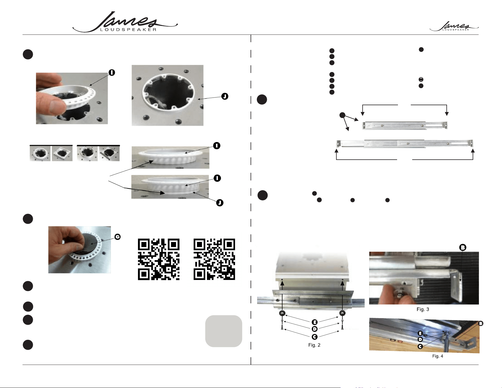
Attach the brackets to the speaker using the
supplied 8/32 screws lock washers & at washers .
B
C
D
E
PAGE 4 PAGE 1
®
®
20210330
2185 Park Place, Minden, Nevada 89423 • Phone: 775.461.7500 | Fax: 775.461.7599 • www.jamesloudspeaker.com
Installation guide for the SA63-4/SA63-7/SA63-8 In-Ceiling Small Aperture
®
Speaker
SA63-4/SA63-7/SA63-8
1) #2 Phillips screwdriver
or drill with #2 Phillips
drill bit
2) Straight edge or level
3) Wood or drywall screws
The brackets (Part No.
SA-BRKT-11-22) are
designed for 16” On-center
constructions, however can
be adjusted to accommodate
construction from 11” to
22.5” joist spacing (Fig. 1).
Tools Required:
Assemble the parts
1
4 - 1.25” Wood or drywall
screws
Parts List: Supplied by Installer
H
1 - SA63-4/SA63-7/SA63-8
2 - Mounting Brackets
4 - 8-32 x 1/2 Pan Head
Machine Screws
4 - #8 Lock Washers
4 - #8 Flat Washers
4 - 6/32 Course Head Screws
1 - Foam Dust Guard
Parts List: Supplied
A
B
C
D
E
F
G
1 - Trim Kit
Spacer Ring(s)
Parts: Ordered Separately
I
J
Tighten these screws just enough to allow
movement for adjustment during installation.
Note: brackets can be mounted to either the sides
of the ends of the speaker enclosure for added
installation flexibility.
Attach the nishing trim kit
P/N SA63-SP-0.125
Recommend testing sub to assure all
components are working.
Attach the nishing trim kit
10
Install foam dust guard.
11
12
Drywall, tape, mud, etc.
13
Safely store the supplied grille for the nal assembly, If you
also received the SA63-4-MOD or SA63-4-MOD module, store
this as well.
14
If you received a SA63-4, SA63-7, or SA63-8 preconstruction
assembly, be sure to order the SA63-4-MOD or SA63-7-MOD module
when ready for nishing.
15
Fig. 1
B
13”
25.5”
There are four trim kits
avilable to choose from
Products suitable for use in
dry outdoor environments
*SA63-4 Sensitivity: 87dB @ 2.83V/1M
Fig. 15
Fig. 18
Fig. 20
SA63-3S-SRSA63-3R-SR SA63-3S-WSA63-3R-W
For 1/2” Drywall omit spacer (a)
For 5/8” Drywall use spacer (b)
If the drywall is in excess of 5/8”
add additional 1/8” spacers as
needed
Fig. 17
Freq. RESPONSE
IMPEDANCE
SENSITIVITY
AMP RANGE
RMS POWER
40-22kHz ±3dB
4 Ohms
88dB @ 2.83V/1M
25-125 Watts
50 Watts
Small Aperture
Installation
Video
Trim Kit
Finishing
Playlist
Fig. 16
Fig. 19
PAGE 3PAGE 2
Installation guide for the SA63-4/SA63-7/SA63-8 In-Ceiling Small Aperture
®
Speaker
SA63-4/SA63-7/SA63-8
®
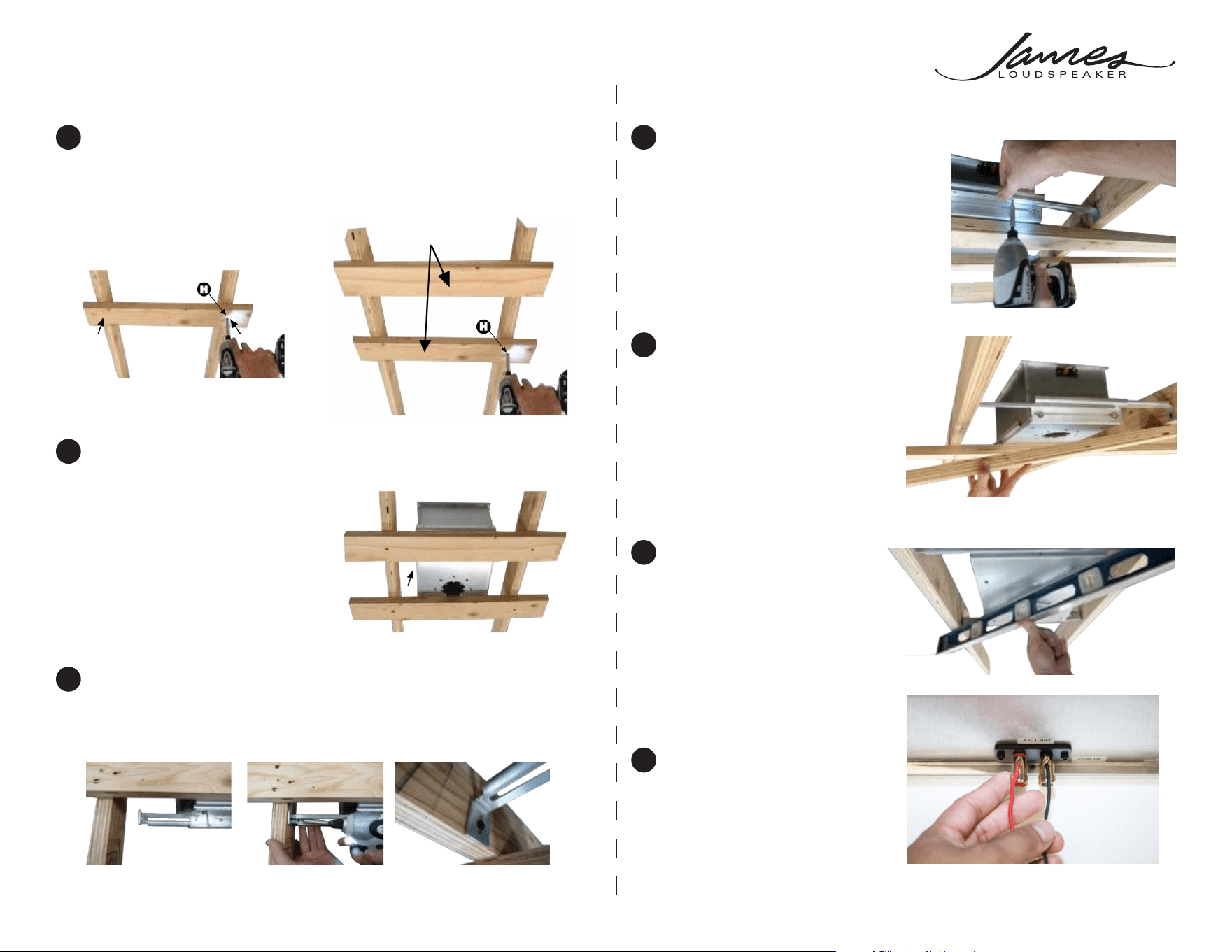
Mount temporary holders to joists
3
Firmly secure the bracket to the speaker
6
Remove the temporary holders from the joists
7
Double check that the face of the speaker
is plumb with joist
8
Strip an insert wires into terminals
9
Place the speaker on top of the temporary holders
4
Fix the brackets to the joists
5
Cut a couple of 2 x 4s or 1 x 2s, a
few inches wider than the ceiling
joists. Then with a couple of drywall
screws, mount the temporary holders
to the joists. (Drywall screws not
included).
Note: The SA63-7 is
pictured in steps 2,4,7.
Procedures for SA63-4
and SA63-8 are
identical.
Expand the bracket to fit from joist to joist (Fig. 8). Then fix to the joists using a drywall
screw (Fig. 9). Make certain the bracket is flush with the joists (Fig. 10). (Drywall screws
not included).
These will help you hold
the speaker up and make
the speaker mount flush
to the future drywall.
Tighten screws enough
to securely fix the bracket
to the speaker enclosure.
Be careful not to strip the
threads on the brackets
(Fig. 11).
You can adjust the side-
to-side position of the
speaker by sliding the
bracket before tightening.
Remove drywall screws
and remove the temporary
holders (Fig. 12).
Adjust if needed (loosen
the bracket slightly and
adjust the speaker’s
position up or down or as
required (Fig. 13).
Minimum 18-gauge wire,
heavier gauges for longer
wire runs.
Fig. 5
Fig. 11
Fig. 12
Fig. 13
Fig. 14
Fig. 7
Fig. 8 Fig. 9 Fig. 10
Fig. 6