ALL
ABOUT
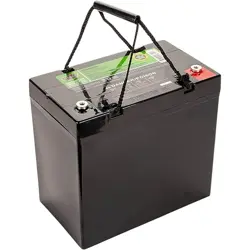
SLA HSL BATTERIES

ADVANTAGES OF SLA BATTERIES
• Maintenance Free
• No Risk Of Leakage
• Low Self-Discharge Rate (3% per Month)
• No-Hazmat Shipping Restrictions
• Safely Used Even In Sideways Position
• Economical-Low Cost Per Cycle
• No Memory Effect
• Wide Temperature Range
• High Discharge Rate
• Long Service Life
• Available in wide variety of terminations
• Easily connected in Parallel and in Series
• Available in High Rate & Deep Discharge
varieties

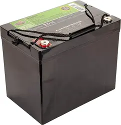
SLA BATTERY CONSTRUCTION
• The nominal voltage of a lead acid battery cell is 2.00 Volts and Open Circuit
Voltage (OCV), is 2.1 volts per cell.
• A 6 volt SLA battery has 3 cells and a 12 volt SLA battery has 6 cells.
• The capacity of an SLA battery is typically measured over 20 hours of discharge, to
a cut off voltage of 1.75 volts/cell.
• SLA’s have one-way valves that release gases if pressure builds up, and these
control venting during charge and discharge. “VRLA” means “Valve Regulated
Lead Acid” Although SLA can be mounted in most any position including sideways,
it is recommended that they not be mounted upside down as this can prevent the
vent from working properly.
• Gas can only escape when internal pressure exceeds the rating of the battery’s
pressure valve. The fact that VRLA are pressurized explains why in extreme cases
of abuse (typically over-charging or extreme heat), they can become seriously
bulged.
• In a VRLA, during what is called the recombination process, hydrogen recombines
under pressure with oxygen to create water inside the battery, which serves to
prevent the battery from drying out during cycling. The one-way pressure relief
valves enforce the recombinant process of hydrogen and oxygen into water.
One-Way Pressure Valve

THE CHEMISTRY
DISCHARGING
• Each cell contains both negative and positive plates.
• The negatively charged plates are the anodes and are pasted with lead (Pb).
• The positively charged plates are the cathodes and are pasted with lead dioxide (PbO2).
• The electrolyte solution between them, whether absorbed in glass mats or suspended in silica gel, is
65% water (H2O) and 35% sulfuric acid (H2SO4).
• When a circuit with load is opened, negatively charged sulfate ions from the sulfuric acid react with
lead at the negative plate.
• This reaction creates lead sulfate on the negative plate and it frees negatively charged electrons
(electricity) that will travel through the open circuit and power a connected device.
• Any excess electrons exiting the device will continue on to the positive terminal and act upon the
positive plates releasing oxygen from the lead dioxide.
• The freed oxygen combines with positively charged hydrogen ions left in the electrolyte solution and
will form water (recombination).
• The lead on the positive plate, freed of its ties to oxygen in its previous dioxide form, reacts with
sulfate ions to form lead sulfate on the positive plate. So lead sulfate (sulfation) now resides on both
plates!
• The end result is: electricity generated, a lead sulfate coating on both positive and negative plates and
a significantly weakened electrolyte lacking in charged ions and holding additional newly created water.
CHARGING
• A charger with greater voltage than the depleted battery reverses the above process.
• It provides an excess of electrons at the negative plates and positive hydrogen ions from the water
are attracted to them.
• The hydrogen ions react with the lead sulfate there to convert to convert it back to lead and the
freed sulfate ions restore the potency of the electrolyte with newly formed sulfuric acid.
• The oxygen from the water reacts with the lead sulfate on the positive plates to turn them once
again into lead dioxide.
• End result takes us right back to where we started with lead negative plates and lead dioxide
positive plates in a refortified sulfuric acid/water solution ready to react and release energy once a
circuit is opened again.

CALCULATING SLA WATTS
The power of an SLA battery is often calculated in
Watts. To calculate Watts, you simply multiply the
Volts of the battery times its amperage. The
formula is P(W)=V(V) X I(A) where P is the power,
V is the Voltage and I is the current calculated in
amperes.
Example: 1.5A * 12V = 18W

SLA BATTERY SHELF LIFE
• SLA batteries have a low self-discharge rate—about 40% per year or 3.3% per month.
• SLA’s can be stored without charging for up to 5 to 6 months when at full capacity,
but doing so is not recommended. At least every 2 to 3 months, you should top charge
them.
• Store SLA batteries in a cool, dry place. The optimum operating temperature for the
lead-acid battery is 25°C (77°F). As a guideline, every 8°C (15°F) rise in temperature
will cut the battery life in half.
• It is always best to store an SLA at a full state-of-charge if at all possible.
• Periodically top charge your SLA batteries.
• Maintaining a low charge causes a condition called sulfation.
• Sulfation is the formation of lead sulfate crystals on the surface and in the pores of
the battery’s lead plates.
• These crystals increase internal resistance causing inefficiency and they will shorten
the battery’s cycle life and eventually leave it non-functional.

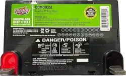
SLA BATTERY LIFE EXPECTANCY
• The life expectancy of an SLA depends on the battery’s application,
frequency of usage, storage and operating temperature, depth of
discharge and number of discharge cycles.
• Life times of 500 to 1200 cycles are common.
• The number of cycles obtainable is directly related to “depth of
discharge”, referred to as DOD.
• SLA’s used in stand-by applications such as alarm systems last longer due
to being on a constant float charge as opposed to frequently being deeply
discharged.
• A discharge cycle is defined as the process of discharging and then
recharging a battery.
• If you fully discharge your battery before you start recharging, you are
performing “deep discharge”.
• Partial discharging is called “shallow discharge”.
• The less deeply you discharge the battery, the more cycles you will get.

AGM (ABSORBED GLASS MAT)
• AGM batteries use very fine glass mats to absorb sulfuric acid battery
electrolyte and hold it in position between the lead calcium alloy plates. This
type of construction leads them to be referred to as “Starved Electrolyte” or
“Acid Starved” batteries.
• These mat/plate “sandwiches” make the battery spill-proof and vibration
resistant. AGM is much more vibration resistant than GEL for this reason.
• AGM is maintenance free and provide good electrical reliability
• AGM stands up well to low temperatures and can withstand freezing
• AGM batteries have a higher energy density than GEL.
• AGM batteries are very responsive to load and are preferred for applications
that require a high burst of power or quick discharge as required in UPS units.
• AGM is commonly used in standby and float applications.
• AGM batteries won’t cycle as many times as GEL.
• But….AGM batteries are typically much less expensive than GEL batteries and
are far more common.

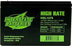
HIGH RATE SLA BATTERIES
• High rate SLA batteries release a greater amount of energy and release it more quickly
than standard SLA’s.
• High rate SLA batteries are of the AGM type and are constructed with lead plates that
are thinner than standard AGM.
• Thinner plates, allow space for more plates, and that means more lead surface area for
reactivity, which enables a quicker, as well as heavier discharge of energy in a short
period of time.
• High Rate SLA batteries are ideal for UPS units or Data Bank support where quick start
up at full rate is important in the event of a power failure.
• The standard for comparison between standard and high rate SLA’s is typically the
number of watts per cell they can deliver in 15 minutes down to an end voltage of 1.69
volts per cell. The 15 minute time frame is relevant to the amount of time a UPS might
need to deliver current during a power outage while an outage is being resolved, the
amount of time that might be required to save files or close applications, or the amount
of the time that might be required to engage other back-up resources such as
generators.
• They must not be used for deep discharge cycles, since the thin lead plates could
disintegrate quickly (plate shedding).
• High Rate SLA’s are designed to maintain a reasonable level of voltage no matter what
the demand.
• If your application requires a higher rate of amps over a shorter time period, then High
Rate Discharge batteries are ideal for you.

• Always choose an appropriate charger. Charge a 12 volt battery with a 12 volt charger and always charger a 6 volt
battery with a 6 volt charger. Charger voltage must be battery voltage.
• If you connect 12 volt batteries in series to get 24 volts, you’ll need a 24 volt charger (or separate the batteries
before charging).
• GEL batteries require a special type of charger and should not be charged with a standard SLA charger that is not
rated for GEL.
• Always charge an SLA battery back to the level it was before any discharge occurred.
• SLA’s do not lend themselves to fast charging and with most types, a full charge takes 14-16 hours if it is completely
discharged. Trickle charging is usually considered the best way to charge an SLA if you have that option.
• A simple formula to estimate charging time is to multiply the amperage of the battery times 1.3 and then divide that
total by the amperage of the charger you are using and that will give you the hours you have to charge the battery,
assuming it was completely discharged.
• Many SLA batteries are rarely cycled or deeply discharged due to their application. Instead they are “float charged”.
• UPS batteries, burglar and fire alarm batteries and exit light batteries are often kept in standby mode and are
constantly being charged by the device are in. They are receiving a constant float voltage of 2.25 – 2.30 volts per
cell.
• A low voltage like that prevents the battery from losing capacity and prolongs battery life expectancy. Most standby
applications have built-in chargers responsible for providing the float charge and maintaining their batteries.
• SLA’s can be over charged and damaged by too much voltage. Keep in mind that undercharging can be as harmful as
overcharging. Undercharging can allow the positive grids to corrode and plates to shed which will decrease the life
of the battery.
SLA CHARGING

• Automatic SLA chargers (smart chargers) often employ the Constant
Current/Constant Voltage (CC/CV) or 3-Stage charge method.
• Using this charging method, a regulated current raises the terminal
voltage until the upper charge voltage limit is reached, at which point
the current drops due to saturation.
• There are three stages in this charging process:
1. The first is the Constant Current Charge stage (sometimes called
Bulk Charge) where the battery charges to about 70% in five to
eight hours.
2. The second stage is the Topping Current Charge (sometimes
called the Absorption Charge) which continues at a lower charge
current for the remaining 30% and provides final saturation of the
battery in about seven to ten hours. The Topping Charge is
essential for the well being of the battery and can be compared
to a little rest after a good meal.☺
3. The third stage or Float Charge then begins and maintains the
battery at full charge. It continues as required and its purpose is
to compensate for any loss caused by self-discharge. FYI, not all
chargers have a float charge feature.
CC/CV OR 3-STAGE CHARGE METHOD
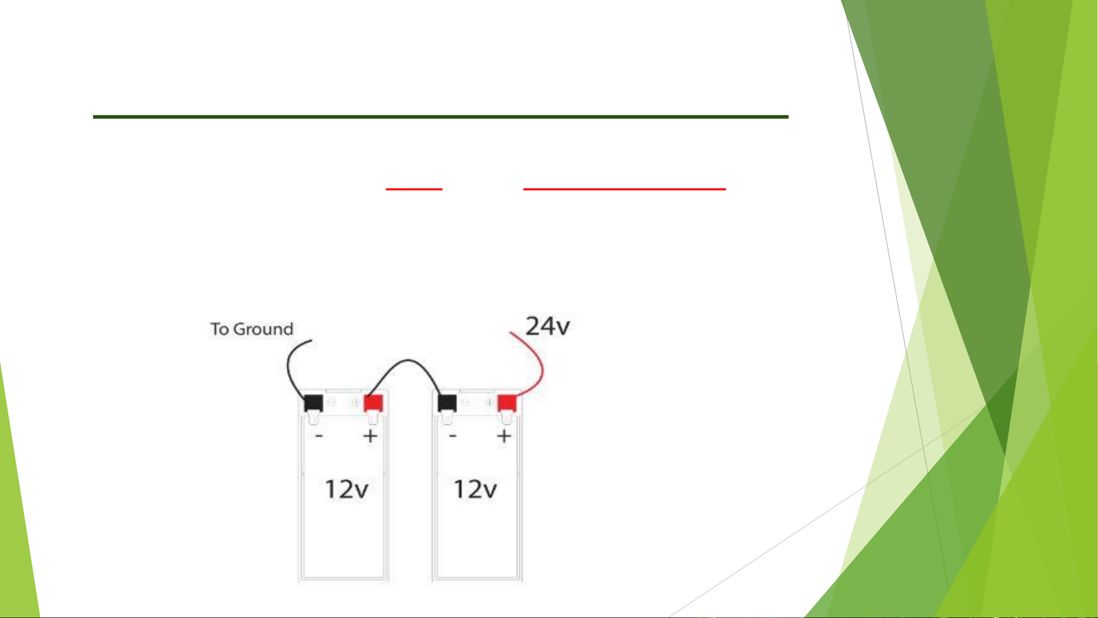
CONNECTING SLA BATTERIES IN SERIES
By connecting SLA batteries in series you are doubling the voltage and
maintaining the same capacity (amp hours). Connect the positive terminal
of the first battery to the negative terminal of the second one. From the
two free terminals connect the positive to the power lead on your device,
and the negative to the ground connection of your application.
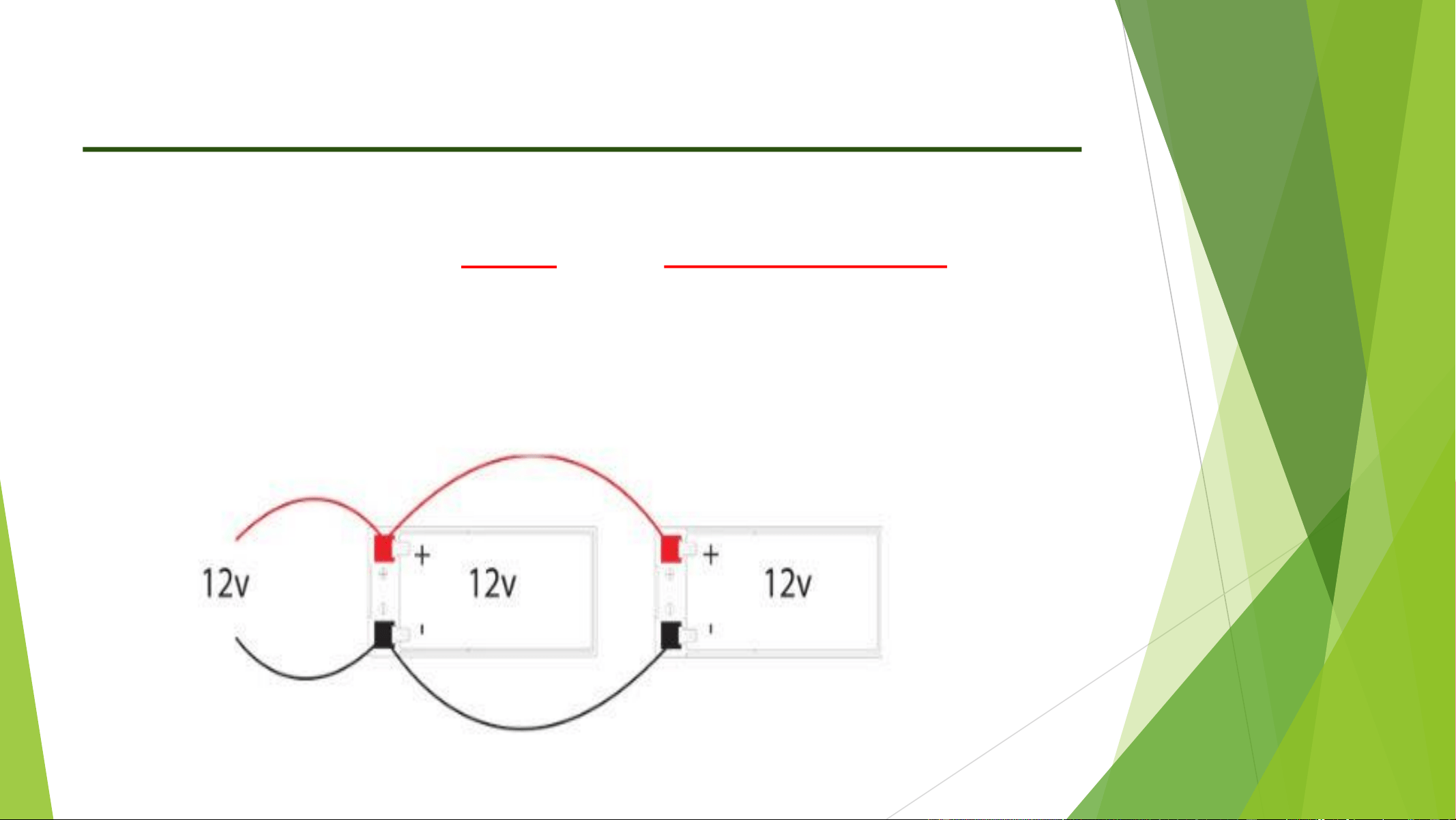
CONNECTING SLA BATTERIES IN PARALLEL
By connecting the batteries in parallel you are doubling the capacity (amp
hours) and maintaining the same voltage. Connect the positive terminal of the
second battery to the positive terminal of the first battery. Do the same with
the negative terminals. Connect your application to the positive and negative
terminals of the first battery.
INTERSTATE SLA’S ARE UL RECOGNIZED
Interstate’s line of SLA’s will display the following mark:
SLA batteries are considered to be components and therefore carry a different mark than
the UL–approved mark you might find on the devices they are installed in. Components
such as SLA batteries are covered by UL’s Recognized Component Program and are intended
to be installed in another device, system or end product. They meet UL’s required safety
standards but only gain an “approved” status when installed and certified in an approved
device, system or end product. When a complete product or system containing UL
Recognized Components is evaluated, the actual end-product evaluation process can be
streamlined due to the use of UL recognized components such as our SLA batteries. Here is
the exact way UL describes this on their website: “UL Component Recognition means that
UL has evaluated components or materials intended for use in a complete product or
system. These components are intended only for end-use products that may be eligible for
UL certification. This [component or material] is Recognized by UL. Representative samples
of this component have been evaluated by UL and meet applicable UL requirements.”
Interstate VRLA batteries are UL Recognized components.