SLM420BT_v1_10/25
USER MANUAL
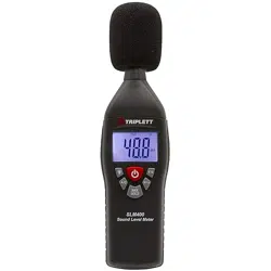
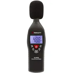
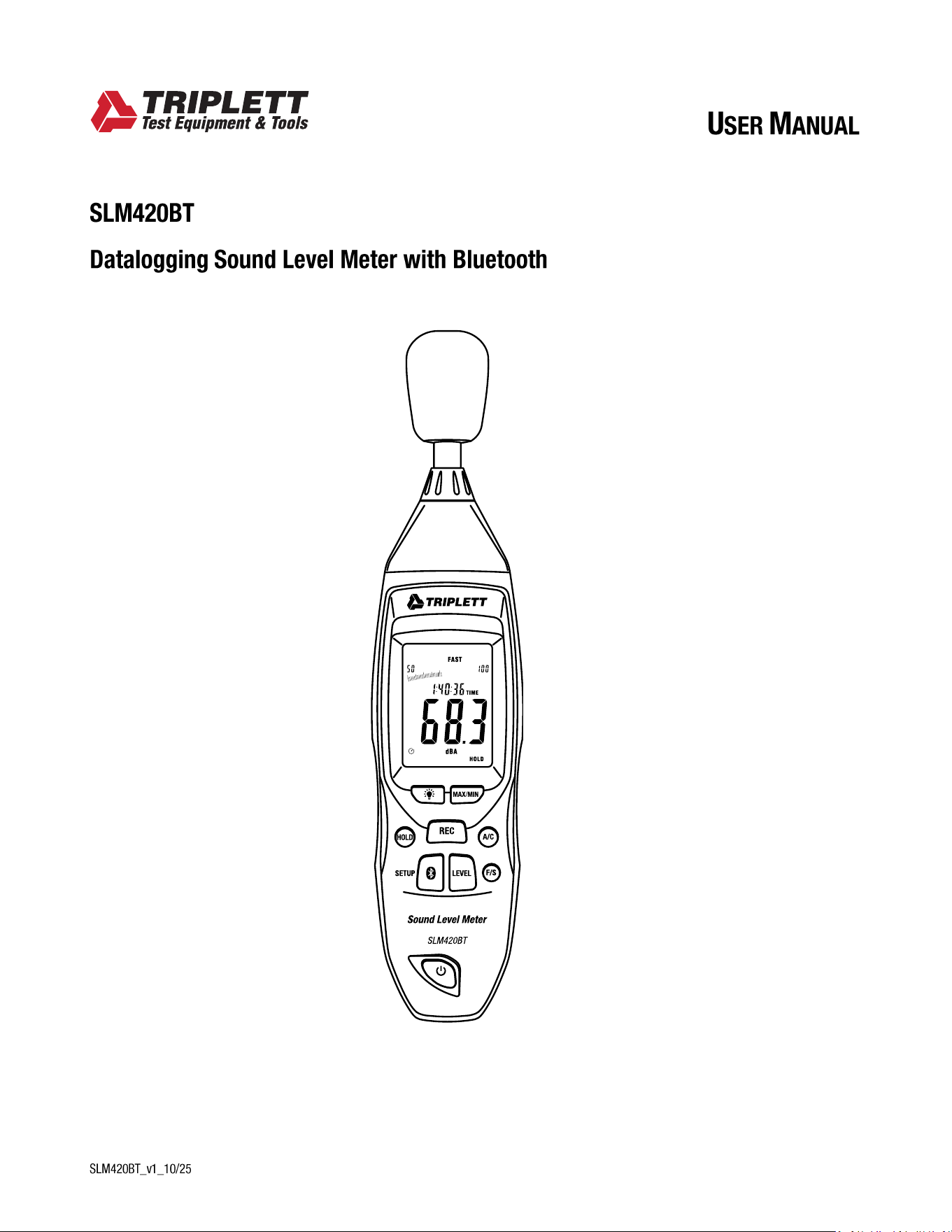
SLM420BT
Datalogging Sound Level Meter with Bluetooth
- 2 -
Introduction
Welcome, and congratulations on your purchase of the Triplett SLM420BT. Engineered for professional accuracy
and reliability, the SLM420BT is designed to measure and monitor noise levels in industrial, commercial, and
environmental applications. Ideal for workplace noise assessment, HVAC and machinery testing, environmental
sound studies, and general acoustic monitoring, this instrument delivers fast, stable, and precise results.
The SLM420BT features A/C frequency weighting, FAST/SLOW response modes, MAX/MIN capture, and a wide
dynamic measurement range to ensure accurate readings across varied noise environments. Equipped with
Bluetooth® wireless technology, the SLM420BT allows real-time data viewing, recording, and analysis through
the supported mobile app for enhanced reporting and field efficiency.
Please read this manual carefully before operating the meter to ensure proper use, safety, and long-term reliability.
What’s in the box:
(1) SLM420BT
(1) User Manual
(1) USB Interface Cable
(1) Wind Screen
(1) 9V Battery
(1) Calibration Pot Screwdriver
Stay updated:
For the most recent version of the user manual, always visit the official Triplett website:
www.triplett.com and search for SLM420BT.
Safety Information
• Read the following safety information carefully before attempting to operate or service the meter.
• Use the meter only as specified in this manual:
Environmental Conditions
Altitude is lower than 2000 meters
Relatively humidity <90%RH
Operation Ambient 0 to 40°
- 3 -
FEATURES
• Thermistor sensor provides stable and accurate temperature compensation
• This unit confirms to the IEC61672-1 CLASS2 for Sound Level Meters
• MAX & MIN measurements
• Over range display
• Under range display
• Weighting A & C
• FAST & SLOW response
• Analog AC/DC outputs for connection to frequency analyzer or X-Y shaft recorder
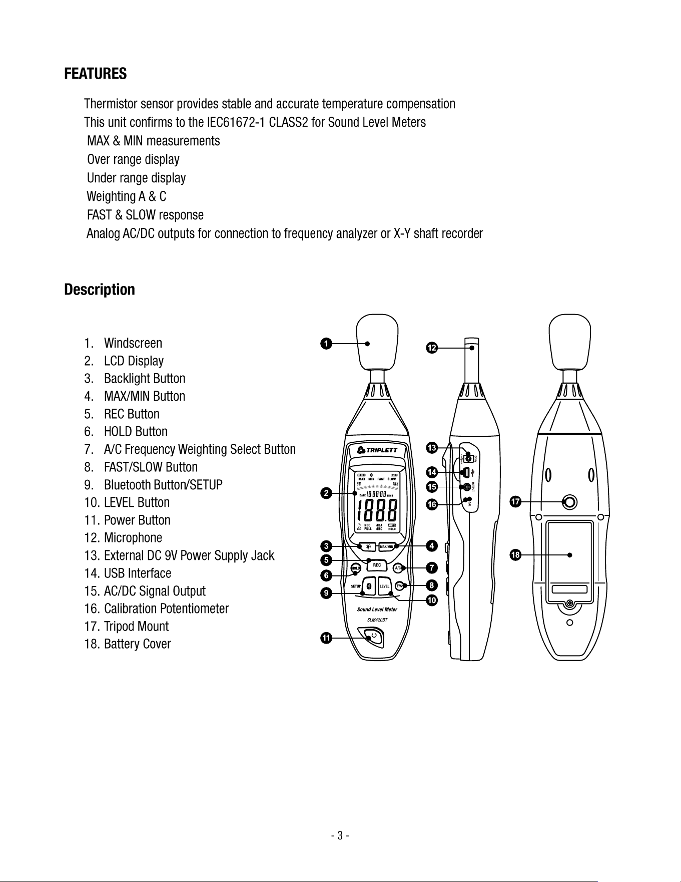
Description
Product Description
1. Windscreen
2. LCD Display
3. Backlight Button
4. MAX/MIN Button
5. REC Button
6. HOLD Button
7. A/C Frequency Weighting Select Button
8. FAST/SLOW Button
9. Bluetooth Button/SETUP
10. LEVEL Button
11. Power Button
12. Microphone
13. External DC 9V Power Supply Jack
14. USB Interface
15. AC/DC Signal Output
16. Calibration Potentiometer
17. Tripod Mount
18. Battery Cover
- 4 -
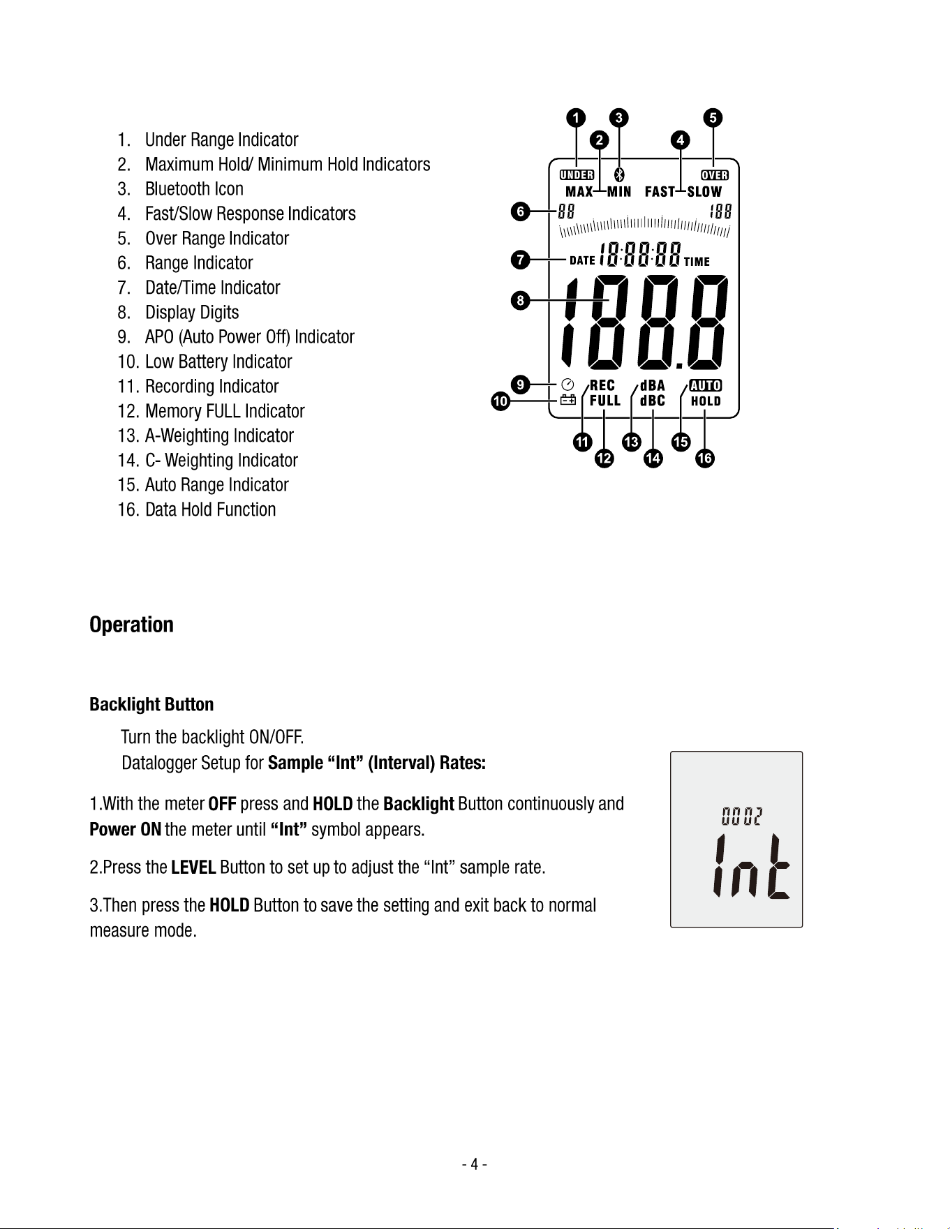
LCD Display Description
1. Under Range Indicator
2. Maximum Hold/ Minimum Hold Indicators
3. Bluetooth Icon
4. Fast/Slow Response Indicators
5. Over Range Indicator
6. Range Indicator
7. Date/Time Indicator
8. Display Digits
9. APO (Auto Power Off) Indicator
10. Low Battery Indicator
11. Recording Indicator
12. Memory FULL Indicator
13. A-Weighting Indicator
14. C- Weighting Indicator
15. Auto Range Indicator
16. Data Hold Function
Operation
Buttons and Functions
Backlight Button
• Turn the backlight ON/OFF.
• Datalogger Setup for Sample “Int” (Interval) Rates:
1.With the meter OFF press and HOLD the Backlight Button continuously and
Power ON the meter until “Int” symbol appears.
2.Press the LEVEL Button to set up to adjust the “Int” sample rate.
3.Then press the HOLD Button to save the setting and exit back to normal
measure mode.
- 5 -
MAX/MIN BUTTON
Maximum/Minimum Hold Function:
• Press the MAX/MIN button once to activate the MAX/MIN measurement mode. The display will
show “MAX”, and the meter will capture and hold the maximum sound level detected. If a higher
sound level is measured, the display will automatically update to the new maximum value.
• Press the MAX/MIN button again to switch to “MIN” mode. The meter will now capture and
hold the minimum sound level detected. If a lower sound level is measured, the display will
update to the new minimum value.
• Press the MAX/MIN button a third time to exit the MAX/MIN measurement mode and return to
normal operation.
REC BUTTON
Datalogger Function
• Press the REC button after powering on the meter to start data recording. The display will show
“REC” to indicate that the data logging function is active.
• Press the REC button again to stop data recording.
Note:
To prevent data errors, do not power o the instrument while the REC function is active. Only
turn o the meter after data recording has stopped and the “REC” icon is no longer displayed.
Adjusting Datalogger Sampling Rate Time
• To access the datalogger response time setting, press and hold the Backlight button before
turning on the meter. While holding the Backlight button, press the Power button to enter the
datalogger setup mode.
• Press the LEVEL button to adjust the memory (sampling) time interval.
• Press the HOLD button to save and conrm the setting.
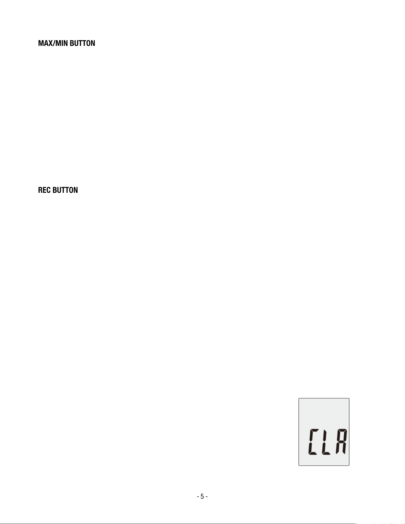
Clearing all Datalogger Memory
• To clear all stored data from the datalogger, press and hold the REC
button before turning on the meter.
• While holding the button, power on the meter.
• When “CLR” appears on the display, release the button. This indicates
that all data in the datalogger memory has been successfully deleted.

- 6 -
HOLD BUTTON
• Press the HOLD button to freeze the current reading on the display.
• Press the HOLD button again to release the hold function and resume normal measurement.
FREQUENCY WEIGHTING SELECT BUTTON
• A: Selects A-weighting, which simulates the frequency response of the human ear and is
commonly used for general sound level measurements.
• C: Selects C-weighting, which measures a wider frequency range and is typically used for
evaluating peak or low-frequency noise levels.
FAST/SLOW BUTTON
Time Weighting Selection:
• FAST: Fast response mode; sampling occurs once every 125 ms, suitable for measuring rapidly
changing noise levels.
• SLOW: Slow response mode; sampling occurs once every 1 second, ideal for monitoring
steady or continuous noise levels.
Internal Clock (Date and Time) Setting and Bluetooth Switch
The SETUP button is used to adjust the internal real-time clock and to initialize or switch the
Bluetooth connection.
Adjusting the Date and Time
1. Press and hold the SETUP button, then power on the meter.
When the “TIME” symbol appears on the display, release the button. The meter will enter
time adjustment mode, and the current date will appear.
- 7 -
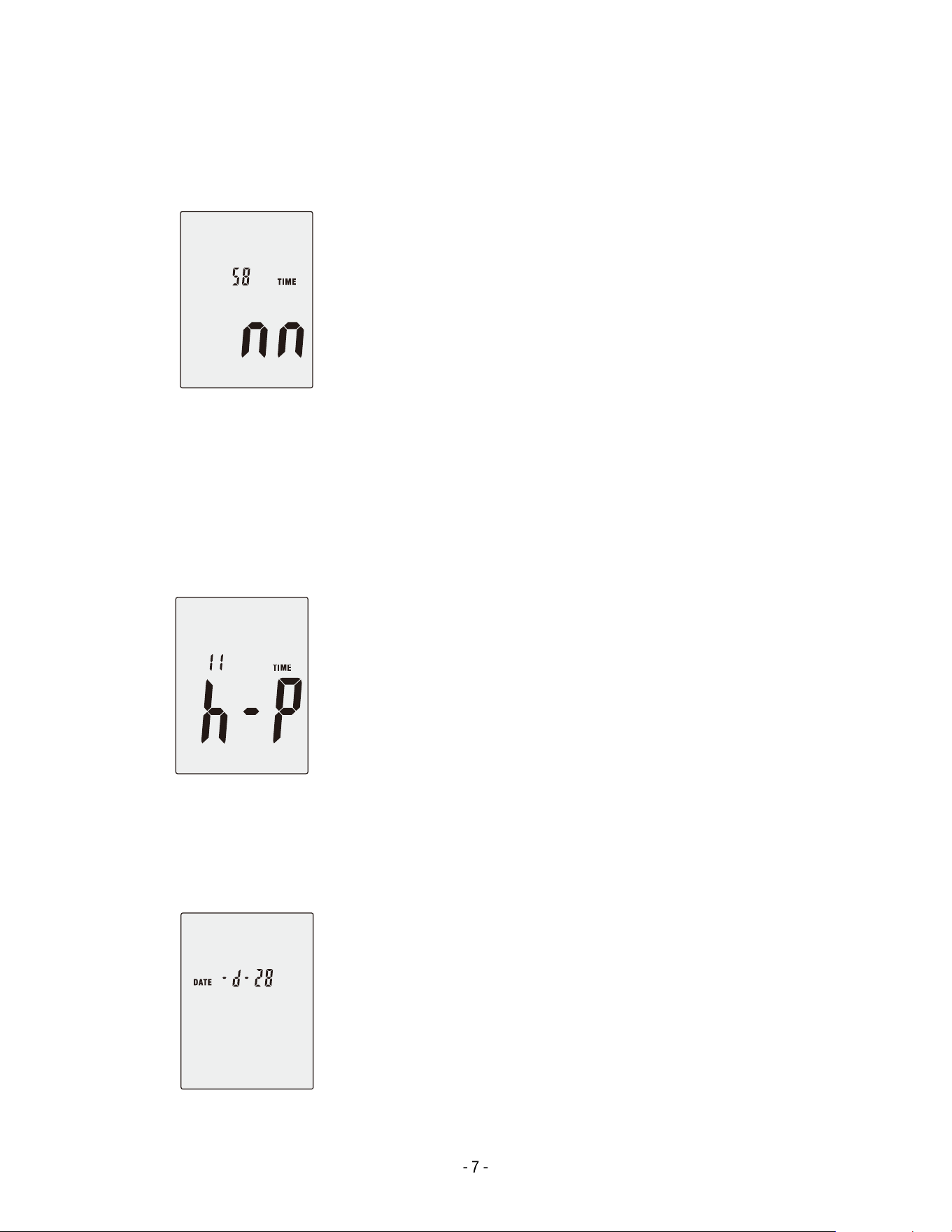
2. Press the SETUP button again to enter the minute adjustment mode.
o Press the LEVEL button to change the minute value.
o Press the HOLD button to conrm and save.
3. Press the SETUP button again to enter the hour adjustment mode.
o The display shows h-P for PM and h-A for AM.
o Press the LEVEL button to change the hourly value.
o Press the HOLD button to conrm and save.
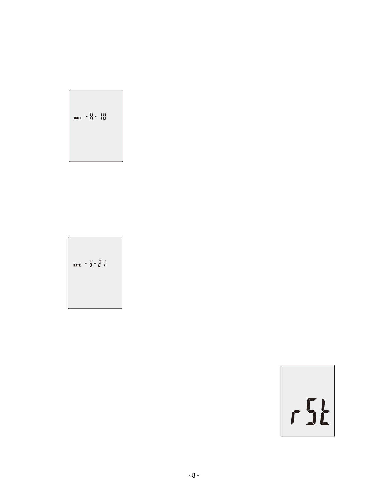
4. Press the SETUP button again to enter the day adjustment mode.
o Press the LEVEL button to change the day.
o Press the HOLD button to conrm and save.
- 8 -
5. Press the SETUP button again to enter the month adjustment mode.
o Press the LEVEL button to change the month.
o Press the HOLD button to conrm and save.
6. Press the SETUP button again to enter the year adjustment mode.
o Press the LEVEL button to change the year.
o Press the HOLD button to conrm and save.
7. Press the SETUP button one nal time to enter time-chip initialization mode.
o Press the HOLD button to conrm initialization.
o The clock and date will return to their factory default
values.
o If the date or time cannot be adjusted after battery
replacement, perform the initialization before resetting the
clock.

- 9 -
USB COMMUNICATIONS SETTING
• Power on the meter and connect it to a computer using the supplied USB cable.
• Open the accompanying PC software and select the correct COM port (for example, COM3 or
COM4).
• Press the SETUP button once. The Auto Power O icon will disappear from the display,
indicating that auto power-o is disabled and that USB data transmission is active.
BLUETOOTH COMMUNICATIONS SETTING
• When Bluetooth communication is active, pressing the SETUP or REC button will cause the
Auto Power O icon to disappear.
• This indicates that auto power-o is disabled and the meter is currently transmitting data via
Bluetooth.
Note:
When data transmission is complete, auto power-o will resume automatically after the preset
timeout period.
LEVEL BUTTON — LEVEL RANGE SELECTION
Each press of the LEVEL button cycles through the available measurement ranges in the
following order:
Low (Lo) → Medium (Med) → High (Hi) → Auto → Low (Lo)
In Auto mode, the meter automatically selects the optimal range based on the detected sound
level.
POWER BUTTON
• Press the Power button to turn the meter ON or OFF.
• The last used settings are retained when the unit is powered back on.
EXTERNAL DC 9 V POWER SUPPLY TERMINAL
• Allows connection to an external DC 9 V power source for continuous operation.
• Connector dimensions: Outer diameter 3.5 mm, Inner diameter 1.35 mm.
- 10 -
USB INTERFACE
The USB signal output operates as a 9600-bps serial interface, allowing direct communication
with PC software for real-time data transfer and analysis.
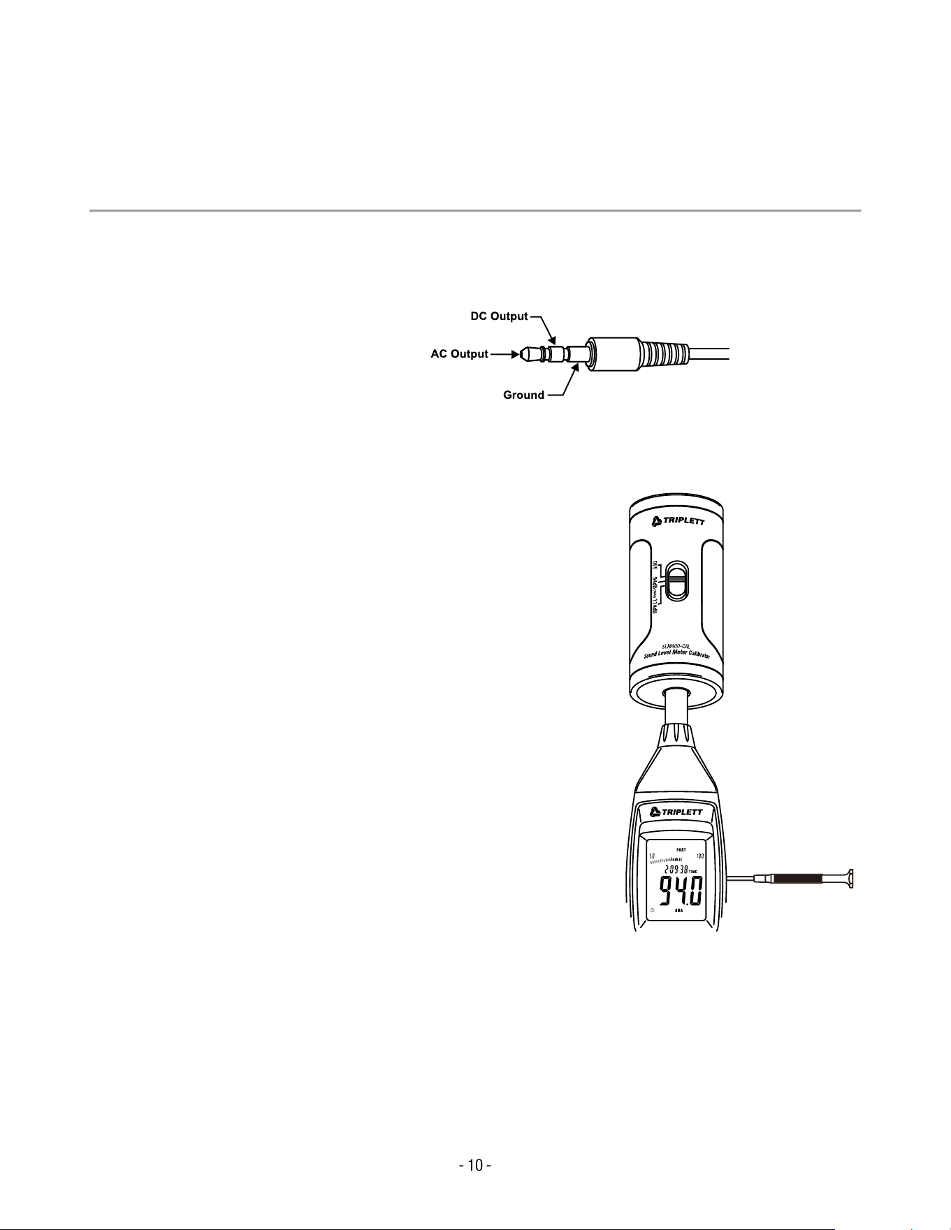
AC/DC SIGNAL OUTPUT (3.5mm OUTLET)
• AC Output Voltage: 1 Vrms corresponding to each measurement range
• AC Output Impedance: 100 Ω
• DC Output Voltage: 10 mV per dB
• DC Output Impedance: 1 kΩ
Tip:
The AC/DC outputs can be connected to external recording devices or analyzers for advanced
signal monitoring and verication.
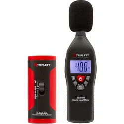
CALIBRATION PROCEDURE
1. Set the following parameters before calibration:
• Frequency Weighting: A-weighting
• Time Weighting: FAST
• Level Range: 50 to 100 dB
2. Insert the microphone carefully into the ½-inch (12.7
mm) cavity of a sound calibrator (set to 94 dB at 1 kHz).
3. Turn on the calibrator and adjust the CAL potentiometer
on the meter until the display reads 94.0 dB.
Note:
All units are factory-calibrated prior to shipment. For best
performance and accuracy, it is recommended to recalibrate
the instrument annually or whenever sensor drift is suspected.

- 11 -
MEASUREMENT PREPARATION
1. Remove the battery cover on the back of the meter and insert one 9 V battery (type 6F22
or equivalent).
2. Replace the back cover securely.
3. When the low battery symbol ( ) appears on the display, the operating voltage is low and
the battery should be replaced.
4. To use an external power source, insert the plug of a DC 9 V adapter (Ø3.5 mm) into the
DC 9 V connector on the side panel of the instrument.
OPERATING PROCEDURE
1. Turn on the meter using the Power button.
2. Press the LEVEL button to select the desired measurement range. Ensure that neither
“UNDER” nor “OVER” appears on the display.
3. Select “dBA” weighting for general environmental noise measurements, or “dBC”
weighting when measuring acoustic materials or low-frequency noise.
4. Select FAST for instantaneous sound level measurements or SLOW for averaged sound
levels.
5. Press the MAX/MIN button to record and display the maximum and minimum noise
levels.
6. Hold the instrument comfortably in your hand or mount it on a tripod, and measure the
sound level at approximately 1 to 1.5 meters (3 to 5 feet) from the sound source.
INSTALLING THE SOFTWARE
1. Start Windows.
Make sure all other programs are closed before installation.
2. Insert the installation CD into your computer’s CD drive.
3. Open the installation directory.
Locate and run the le SETUP.exe in the DISK1 folder.
Follow the on-screen instructions to install the software in your preferred directory.
4. Install the USB Driver (CP210X).
o Connect the meter to your computer using the USB cable.

- 12 -
o When prompted, install the CP210X driver.
o If Windows requests a location for the driver, browse to:
My Computer → Properties → Hardware → Device Manager → Ports (COM & LPT)
and conrm that CP210X USB to UART Bridge appears under Ports.
USB Driver Installation (Manual Method)
• Copy the CP210X WIN Drivers to a directory such as:
C:\usb_driver
• Connect the meter to your computer using the USB cable.
When Windows displays “New Hardware Found”, select Install from a specic location, then
browse to:
C:\usb_driver
• After successful installation, a new COM port (such as COM3 or COM4) will appear in the
Device Manager.
Connecting the Meter
1. Once the driver installation is complete, launch the installed application software.
2. Connect the meter to your computer via the USB interface.
3. In the software, select the COM port corresponding to the CP210X driver (for example,
COM3 or COM4).
4. Press the SETUP button on the meter.
The Auto Power O icon will disappear, indicating that the meter is actively transmitting
data to the computer.
Note:
For additional information about data logging, exporting, or graphing functions, refer to the Help
section within the installed software.
- 13 -
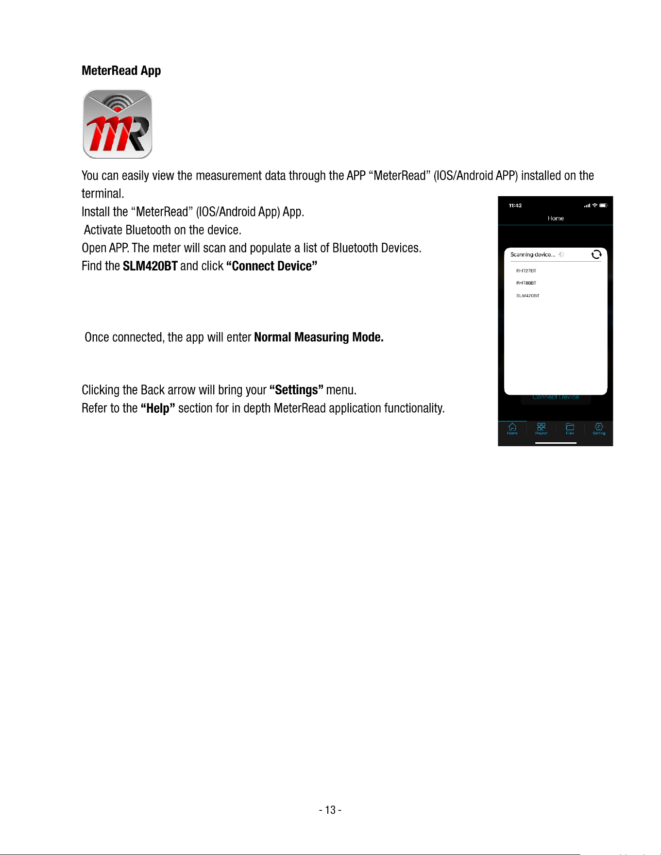
MeterRead App
• You can easily view the measurement data through the APP “MeterRead” (IOS/Android APP) installed on the
• terminal.
• Install the “MeterRead” (IOS/Android App) App.
• Activate Bluetooth on the device.
• Open APP. The meter will scan and populate a list of Bluetooth Devices.
• Find the SLM420BT and click “Connect Device”
• Once connected, the app will enter Normal Measuring Mode.
• Clicking the Back arrow will bring your “Settings” menu.
• Refer to the “Help” section for in depth MeterRead application functionality.
- 14 -
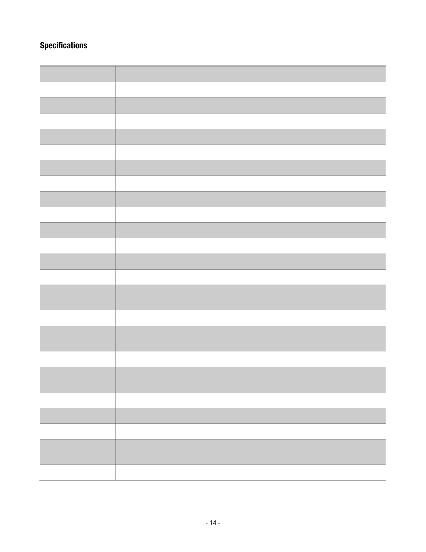
Specifications
Feature
Description
Standard Applied
IEC 61672-1 Class 2
Accuracy
±1.4 dB
Frequency Range
31.5 Hz to 8 kHz
Dynamic Range
50 dB
Level Ranges
Lo: 30 to 80 dB / Med: 50 to 100 dB / Hi: 80 to 130 dB / Auto: 30 to 130 dB
Frequency Weighting
A / C
Time Weighting
FAST (125 ms) / SLOW (1 s)
Microphone
½ in. (12.7 mm) electret condenser microphone
Display
4-digit LCD display with 0.1 dB resolution
Display Update Rate
2 times per second
MAX Hold
Captures and displays maximum reading
MIN Hold
Captures and displays minimum reading
Data Hold
Freezes the current reading on display
Alarm Function
“OVER” indicates input above range limit; “UNDER” indicates input below range limit
Analog Output
AC = 1 Vrms (approx.) / DC = 10 mV per dB; AC output impedance 100 Ω; DC output
impedance 1 kΩ
Data Output
USB interface (9600 bps) and Bluetooth wireless communication
Auto Power O
Meter automatically shuts down after approximately 15 minutes of inactivity (can be
disabled)
Power Supply
One 9 V battery (006P, NEDA 1604, or IEC 6F22) or DC 9 V adapter (Ø 3.5 mm plug)
Operating
Temperature
32 °F to 104 °F (0 °C to 40 °C)
Operating Humidity
10 % RH to 90 % RH
Storage Temperature
14 °F to 140 °F (–10 °C to 60 °C)
Storage Humidity
10 % RH to 75 % RH
Dimensions (L × W ×
H)
10.9 × 3.0 × 2.0 in (278 × 76 × 50 mm)
Weight
12.3 oz (350 g) including battery
- 15 -
Warranty Statement
Triplett Test Equipment offers a two-year warranty to the original purchaser of its products. We guarantee that
our products will be free from defects in workmanship and materials for two (2) years from the purchase date.
This warranty does not cover:
▪ Products purchased from unauthorized distributors.
▪ Items that have been repaired or altered by unauthorized individuals.
▪ Damage from misuse, abuse, misapplication, negligence, or accidents.
▪ Products with altered, defaced, or removed serial numbers.
▪ Accessories, including batteries.
Copyright © 2026
Triplett www.triplett.com