
Shenzhen Uascent Technology Co., Ltd
www.uascent-iot.com
1
Office: Zhongxing Hotel (Qianhai HOP
International),No.19,Xinghua 1st Road
(Extension),Haiwang Community,Xin'an
Street,Bao'an District,Shenzhen,2101,CHINA
TEL: +86-0755-82571152
E-MAIL: [email protected]
Website: www.uascent-iot.com
Customer Approval : Company
Title
Signature
Date
Uascent
UAM053
Wi-Fi Single-band 1T1R 802.11b/g/n/ax
Module Datasheet
Shenzhen Uascent Technology Co., Ltd
Universal Ascent Holdings Limited


Shenzhen Uascent Technology Co., Ltd
www.uascent-iot.com
UAM053
3
CONTENTS
1 Overview. ................................................................................................................................ 4
1.1 Introduction. ...........................................................................................................................4
1.2 Features. ............................................................................................................................... 4
1.3 Recommended Operating Rating. ......................................................................................... 4
1.4 Reference power consumption for conventional continuous operation. ................................ 4
1.5 ESD Specifications ................................................................................................................5
2 Module usage precautions. ................................................................................................... 5
3 WiFi Specification. ................................................................................................................. 5
4 Pin Descriptions. .................................................................................................................... 6
4.1 Pin Outline. ............................................................................................................................6
4.2 Pin Definition. ........................................................................................................................ 6
5 Dimensions. ............................................................................................................................ 7
5.1 Module Picture...................................................................................................................... 7
5.2 Module Mechanical Dimensions. ...........................................................................................8
5.3 PCB Layout Reference. .........................................................................................................8
6 Antenna Information. ............................................................................................................. 9
6.1 Antenna type. ........................................................................................................................ 9
6.2 Module layout considerations. ............................................................................................... 9
7 Environmental Requirements. .............................................................................................. 9
7.1 Recommended Reflow Profile. .............................................................................................. 9
7.2 Note. ....................................................................................................................................10
7.3 Humidity sensitive control. ...................................................................................................11
8 Package style. .......................................................................................................................12
8.1 Packaging Detail. .................................................................................................................12
9 Transport regulations. ......................................................................................................... 12
10 Disclaimer and copyright notice. ......................................................................................12
11 Attention. .............................................................................................................................13
12 FCC statements: .................................................................................................................13
UAM053
Uascent Technology Co.,
4
www.uascent-iot.com
1 Overview.
1.1 Introduction.
UAM053 is a cost-effective WIFI+BLE module developed by Uascent Technology,
supporting Bluetooth dual mode 5.2 and IEEE 802.11 b/g/n/ax protocol standards,
lightweight TCP/IP protocol stack, STA, AP, and Direct modes, and Matter protocol. Users
can use this module to add networking functions to existing devices or build independent
network controllers.
1.2 Features.
Operate at ISM frequency bands (2.4GHz).
Standard IEEE 802.11b/g/n/ax.
Support WiFi+Bluetooth 5.2.
Support Wi-Fi and BLE coexist.
Support BLE assists in fast Wi-Fi connection.
Built-in single core RISC-V MCU with a main frequency of up to 320MHz, can be
used as an application processor.
Built-in 64KB ROM,512KB SRAM,4MByte Flash ,32byte eFuse.
Built-in TR switch, BALUN, LNA, PA, and PCB onboard antenna.
Support remote firmware OTA upgrade.
Support STA , AP, STA+APand Direct working modes.
Support WPA/WPA2 /WPA3 security protocol.
1.3 Recommended Operating Rating.
Description
Min
Typ
Max
Unit
Ambient Temperature (TA)
-20
25
85
deg.C
Vcc
3.0
3.3
3.6
V
(VOL)
Output low voltage
VSS
/
VSS+0.3
V
(VOH)
Output high voltage
VCC-0.3
/
VCC
V
1.4 Reference power consumption for conventional continuous
operation.
Parameter
Condition / Notes
Typ.
Unit
TX model
I
RF
11b 11M
280
mA
I
RF
11g 54M
250
mA
I
RF
11n HT20 MCS7
250
mA
I
RF
11n HT40 MCS7
250
mA
UAM053
Uascent Technology Co.,
5
www.uascent-iot.com
I
RF
11ax HE20 MCS7
250
mA
I
RF
11ax HE40 MCS7
250
mA
RX model
I
RF
11b 11M
80
mA
I
RF
11g 54M
80
mA
I
RF
11n HT20 MCS7
80
mA
I
RF
11n HT40 MCS7
80
mA
I
RF
11ax HE20 MCS7
80
mA
I
RF
11ax HE40 MCS7
80
mA
1.5 ESD Specifications
Item
Description
Value
Unit
Human Body Mode (HBM)
Electrostatic Discharge
Tolerance under Human
Body Model
±4
KV
CDM
Electrostatic Discharge
Tolerance under Charged
Device Model
±0.2
KV
2 Module usage precautions.
When using the WIFI module of Uascent Technology, a certain tolerance should be reserved for the
output current of the power supply. It is recommended that the output current of the power supply be
≥ 500mA, and a suitable power supply IC packaging should be selected. When supplying LDO power,
attention should be paid to the issue of heating, and when supplying DC-DC power, attention should
be paid to the issue of overshoot at the moment of power on.
3 WiFi Specification.
Features
Descriptions
Main Chipset
BEKEN
:
BK7235
Operating Frequency
2.412~2.484GHz
Operating Voltage
3.0~3.6V
WIFI Standard
IEE 802.11b/g/n/ax
PHY Data rates
Wi-Fi: 802.11b: 11, 5.5, 2, 1 Mbps
802.11g: 54, 48, 36, 24, 18, 12, 9, 6 Mbps
HT20 MCS0-MCS7
HT40 MCS0-MCS7
HE20 MCS0-MCS7
HE40 MCS0-MCS7
Transmit Output
Wi-Fi: 802.11b@11Mbps 16±2dBm
802.11g@54Mbps 15±2dBm
UAM053
Uascent Technology Co.,
6
www.uascent-iot.com
Power
802.11n@HT20 MCS7 14±2dBm
802.11n@HT40 MCS7 14±2dBm
802.11ax@HE20 MCS7 14±2dBm
802.11ax@HE40 MCS7 14±2dBm
EVM
802.11b /11Mbps: EVM≦-10dB
802.11g /54Mbps: EVM
≦
-25dB
802.11n /HT20 MCS7: EVM
≦
-27dB
802.11n /HT40 MCS7: EVM
≦
-27dB
802.11ax /HE20 MCS7: EVM
≦
-27dB
802.11nax/HE40 MCS7: EVM
≦
-27dB
Receiver Sensitivity
(HT20)
802.11b@8% PER11Mbps≦ -88dBm
802.11g@10% PER 54Mbps≦-74dBm
802.11n@10% PER MCS 7≦-70dBm
Operating Channel
Wi-Fi 2.4GHz:
11: (Ch. 1-11) – United States(North America)
13: (Ch. 1-13) – Europe
14: (Ch. 1-14) – Japan
Antenna
PCB onboard antenna
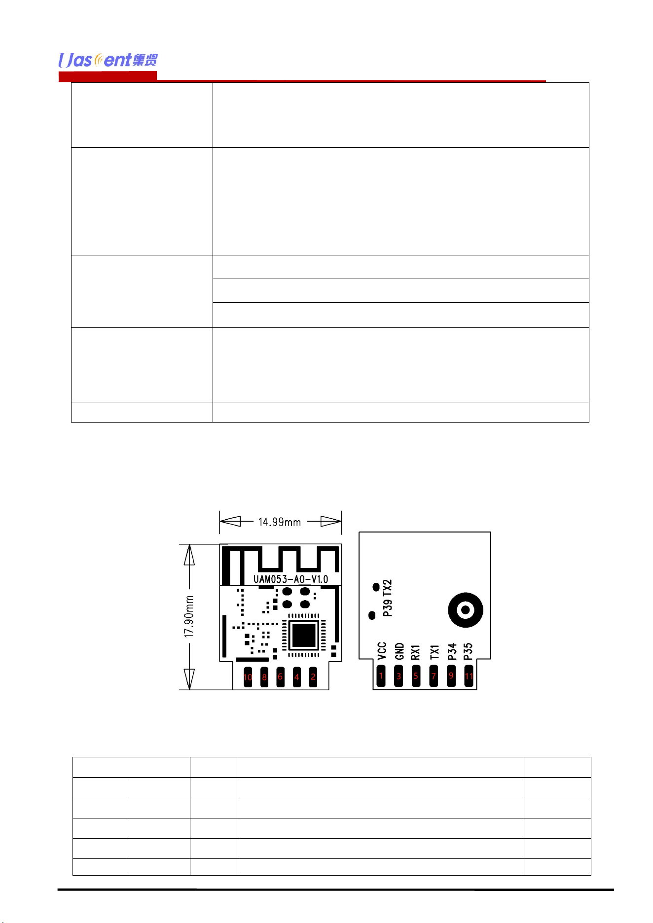
4 Pin Descriptions.
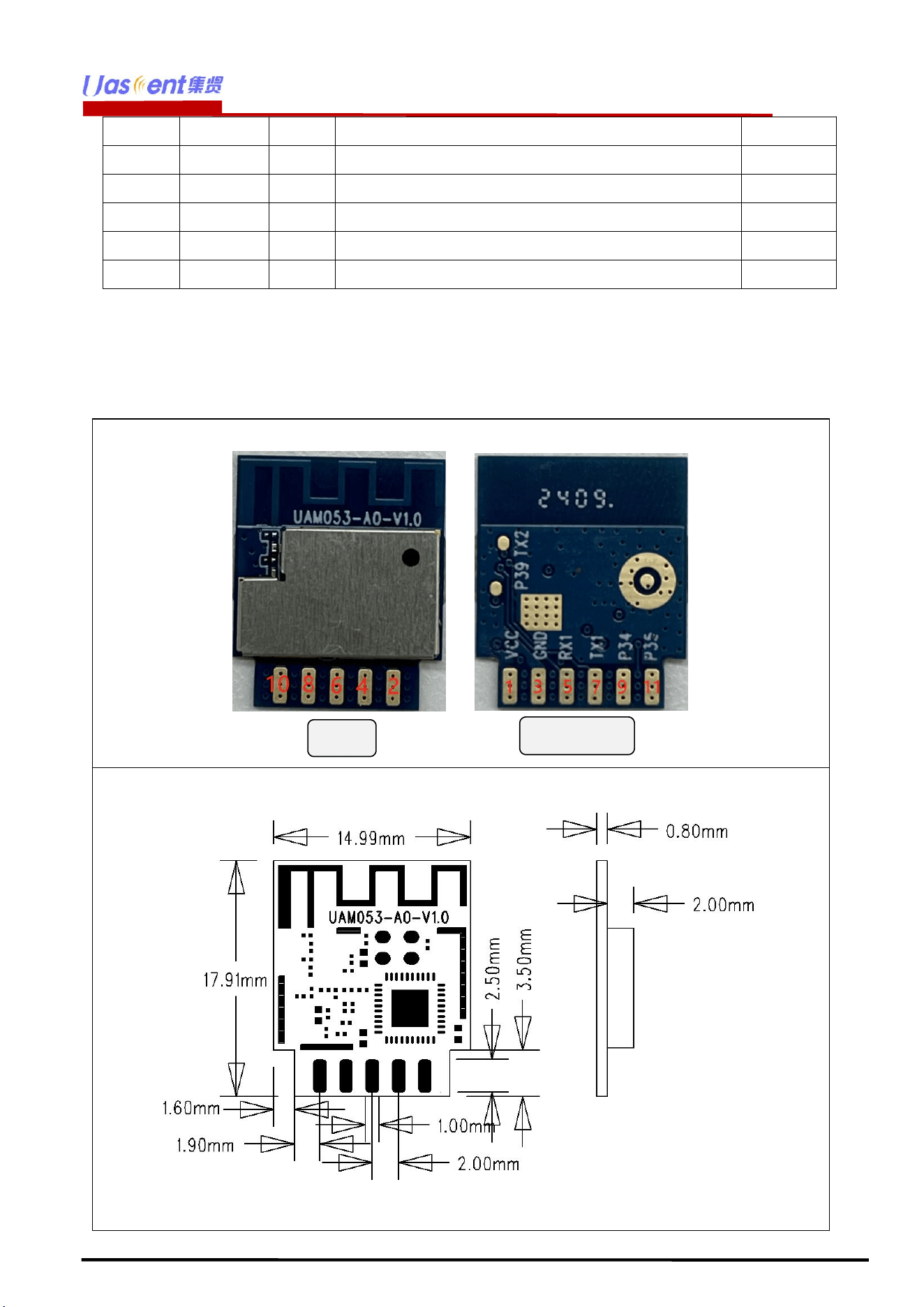
4.1 Pin Outline.
<TOP> <BOT>
4.2 Pin Definition.
Pin No.
Name
Type
Description
Voltage
1
3V3
P
Supply 3.3V
2
P32
I/O
GPIO32/CIS_PXD0/PWM6/Touch sensor 6
3
GND
P
Ground
4
P33
I/O
GPIO33/CIS_PXD1/PWM7/Touch sensor 7
5
RX1
I/O
UART_RX1/GPIO10
UAM053
Uascent Technology Co.,
7
www.uascent-iot.com
6
P25
I/O
GPIO25/IRDA/PWM5/ADC1
7
TX1
I/O
UART_TX1/GPIO11
8
ADC4
I/O
ADC4/GPIO28/I2S_MCLK/Touch sensor 2
9
P34
I/O
GPIO34/CIS_PXD2/PWM8/Touch sensor 8
10
CEN
I/O
Chip enable, active high
11
P35
I/O
GPIO35/PXD3/PWM9/Touch sensor 9
※ P:POWER I:INPUT O:OUTPUT
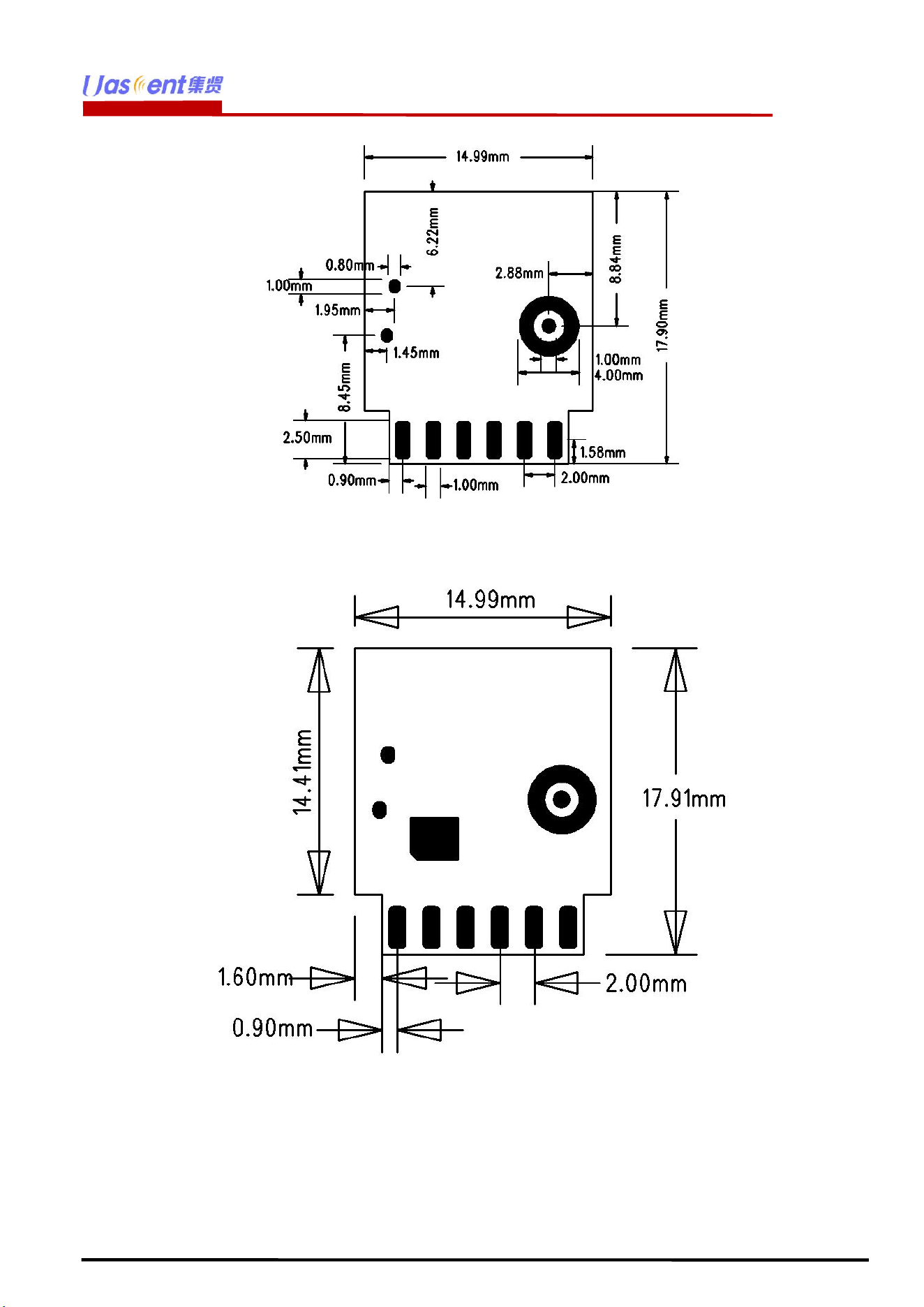
5 Dimensions.
5.1 Module Picture.
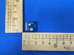
L:17.91 x W:14.99 x H:2.8 (±0.2) unit=mm
TOP
BOTTOM
UAM053
Uascent Technology Co.,
9
www.uascent-iot.com
6 Antenna Information.
6.1 Antenna type.
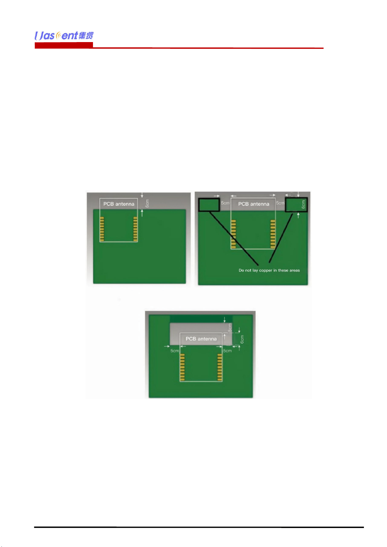
This module antenna type is PCB on-board antenna with antenna gain of -1.2dBi (MAX)
6.2 Module layout considerations.
The UAM053 module shall be welded to the PCB board. In order to obtain the best RF
performance. Under the PCB on-board antenna, there should be no copper laying, device
and wiring. During PCB design, the corresponding area should be cleared. As shown in the
following figure.
7 Environmental Requirements.
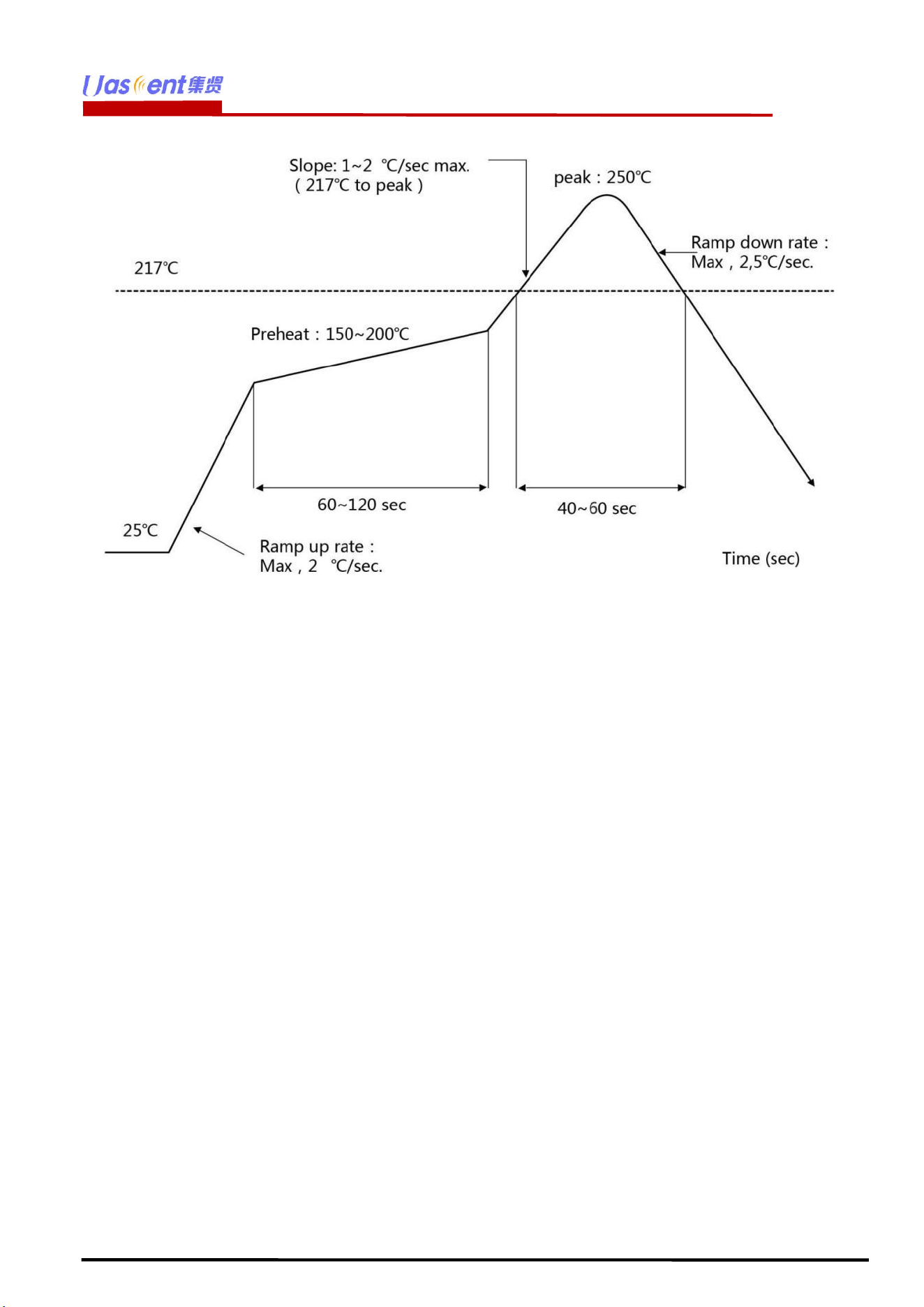
7.1 Recommended Reflow Profile.
Referred to IPC/JEDEC standard.
Peak Temperature : <245°C
Number of Times :
≤
2 times
UAM053
Uascent Technology Co.,
10
www.uascent-iot.com
7.2 Note.
Note:Take and use the module, please insure the electrostatic protective measures.
1. Reflow soldering temperature should be according to the customer the main size of
the products, such as the temperature set at 250 + 5
℃
for the MID motherboard.
About the module packaging, storage and use of matters needing attention are as
follows:
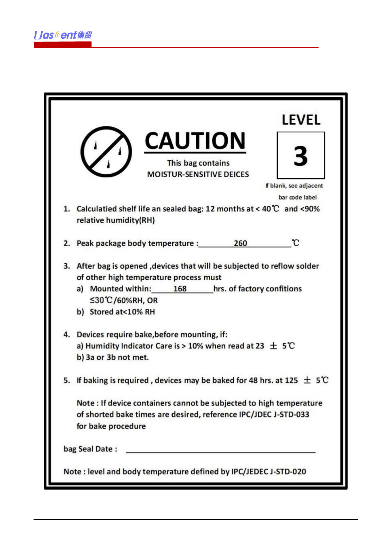
2. The module of the reel and storage life of vacuum packing: 1). Shelf life: 8 months,
storage environment conditions: temperature in: < 40
℃
, relative humidity: < 90% r.h.
3. The module vacuum packing once opened, time limit of the assembly:
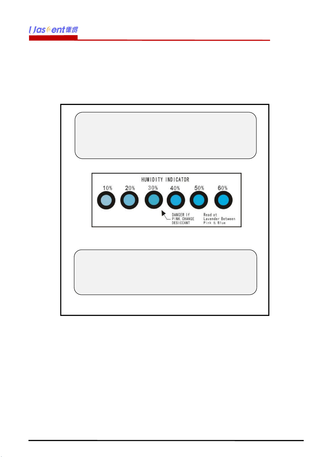
Card:1) check the humidity display value should be less than 30% (in blue), such as: 30%
~ 40% (pink), or greater than 40% (red) the module have been moisture absorption. 2.)
factory environmental temperature humidity control:
≦
-30
℃
,
≦
60% r.h..
3). Once opened, the workshop the preservation of life for 168 hours.
4. Once opened, such as when not used up within 168 hours:
1). The module must be again to remove the module moisture absorption.
2). The baking temperature: 125
℃
, 8 hours.
3). After baking, put the right amount of desiccant to seal packages.
UAM053
Uascent Technology Co.,
12
www.uascent-iot.com
8 Package style.
8.1 Packaging Detail.
The module and the humidity indicator card are placed together in vacuum anti-static
packaging, separated by a certain amount of paper, and neatly placed in the packaging
box.The packaging must have reliable moisture-proof and anti-collision measures.
9 Transport regulations.
In the process of logistics or express transportation, attention should be paid to handling with
care to avoid direct rain and snow.
10 Disclaimer and copyright notice.
All information in this document is provided according to the product status quo and subject to
change without notice.
The contents of this document disclaim any warranties, including any warranties of fitness for
sale, fitness for a particular purpose or non-infringement, and any warranties mentioned
elsewhere in any proposal, specification or sample.
Note1:
There is a "triangular arrow" on the humidity indicator card
indicating at 30%RH (as shown in the picture below). If the
chemical changes to pink in the circle it points to, the
element is damp and needs baking.
Note2:
Please confirm the packaging style with our sales staff
before purchasing this product. If no packing style is
specified before purchase, we will ship the goods by our
own choice of packing method.

UAM053
Uascent Technology Co.,
13
www.uascent-iot.com
This document is not liable for any infringement of patent rights arising from the use of the
information contained in this document.
This document does not grant any license, express or implied, to use any intellectual property
rights, estoppel or otherwise.
All trademarks mentioned herein are the property of their respective owners.
11 Attention.
Due to product version upgrade or other reasons, the content of this manual may be changed.
Shenzhen Uascent Technology Co., Ltd. reserves the right to modify the content of this manual
without any notice or prompt. If users need to obtain the latest product information, please
apply for the final document with our company.This manual is only used as a guide. Shenzhen
Uascent Technology Co., Ltd. tries its best to provide the latest information in this manual, but
does not guarantee that the content of the manual is completely accurate.
None of the statements, information and recommendations contained in this manual constitute
any warranty, express or implied.
12 FCC statements:
The Module is designed to comply with the FCC statement. FCC ID is 2A68E-UAM053. The host system
using Module, should have label indicated it contain modular’s FCC ID: 2A68E-UAM053. This radio module
must not installed to collocate and operating simultaneously with other radios in host system additional
testing and equipment authorization may be required to operating simultaneously with other radio.
The Module and its antenna must not be co-located or operating in conjunction with any other transmitter or
antenna within a host device.
The modular must be installed in the host that assign by Company name: Shenzhen Uascent Technology
Co.,Ltd, Model no.: UAM053 if other host types used would need further evaluation and possible C2PC if
they are not significantly similar to the one tested The WIFI Module is designed for a compact PCB design. It
should be installed and operated with host or other minimum distance of 20 centimeters between the radiator
and your body." To comply with FCC regulations limiting both maximum RF output power and human
exposure to RF radiation, the maximum antenna gain including cable loss in a mobile-only exposure
condition must not exceed -1.2 dBi in 2.4G. The module uses PCB antenna, the antenna is sold with the
module.
Notice to OEM integrator
The end user manual shall include all required regulatory information/warning as show in this manual. The
OEM integrator is responsible for testing their end-product for any additional compliance requirements
required with this module installed. If the final product contains circuits of other FCC PART 15 Subparts, the
final host product still requires Part 15 Subpart B compliance testing with the modular transmitter installed
The intended use is generally not for the general public. It is generally for industry/commercial use. The
connector is within the transmitter enclosure and can only be accessed by disassembly of the transmitter that
is not normally required, the user has no access to the connector. Installation must be controlled. Installation
requires special training.
This device complies with Part 15 of the FCC Rules.
This equipment should be installed and operated with a minimum distance of 20 cm between the radiator
and your body.
2.2
This module has been assessed against the following FCC rule parts: CFR 47 FCC Part 15 C (15.247. DTS).
lt is applicable to the modular transmitter

UAM053
Uascent Technology Co.,
14
www.uascent-iot.com
2.3
This radio transmitter Module has been approved by Federal Communications Commission to operate with
the antenna types listed below, with the maximum permissible gain indicated. Antenna types not included in
this list that have a gain greater than the maximum gain indicated for any type listed are strictly prohibited for
use with this device.
The concrete contents to check are the following three points.
1) Maximum antenna gains are shown in item 2.7 below.
2) Should be installed so that the end user cannot modify the antenna
3) Feed line should be designed in 50ohm
Fine-tuning of return loss etc. can be performed using a matching network.
The antenna shall not be accessible for modification or change by the end user.
2.4
The module complies with FCC Part 15.247 and apply for Single module approval.
2.5
Trace antenna designs: applicable.
Any deviation(s) from the defined parameters of the antenna trace, as described by the instructions, require
that the host product manufacturer must notify the module grantee that they wish to change the antenna
trace design. in this case, a Class ll permissive change application is required to be filed by the grantee, or
the host manufacturer can take responsibility through the change in FCC lD (new application) procedure
followed by a Class ll permissive change application.
The device must be professionally installed.
The intended use is generally not for the general public.
It is generally for industry/commercial use.
The connector is within the transmitter enclosure and can only be accessed by disassembly of the
transmitter that is not normally required.
The user has no access to the connector.
Installation must be controlled.
Installation requires special training.
2.6
This equipment complies with FCC radiation exposure limits set forth for an uncontrolled environment. This
equipment should be installed and operated with a minimum distance of 20cm between the radiator & your
body. This transmitter must not be co-located or operating in conjunction with any other antenna or
transmitter.
2.7
The following antennas have been certified for use with this module.
Only antennas of the same type with equal or lower gain may also be used with this module.
Other types of antennas and/or higher gain antennas may require the additional authorization for operation.
The installer should use unique antenna connector and Antenna types not included in this list that have a
gain greater than the maximum gain indicated for any type listed are strictly prohibited for use with this
device. The manufacturer of module will inform installer to meet with the FCC part 15.203 in the warning
part.
Antenna Specification list below:
BLE/2.4G WIFI:
Antenna type: PCB Antenna
The max antenna gain (in dBi): -1.2 dBi
2.8
Please notice that if the FCC identification number is not visible when the module is installed inside another
device, then the outside of the device into which the module is installed must also display a label referring to
the enclosed module. This exterior label can use wording such as "Contains FCC ID: 2A68E-UAM053 "; any
similar wording that expresses the same meaning may be used.
2.9

UAM053
Uascent Technology Co.,
15
www.uascent-iot.com
Testing of the host product with all the transmitters installed - referred to as the composite investigation test-
is recommended, to verify that the host product meets all the applicable FCC rules. The radio spectrum is to
be investigated with all the transmitters in the final host product functioning to determine that no emissions
exceed the highest limit permitted for any one individual transmitter as required by Section 2.947(f). The host
manufacturer is responsible to ensure that when their product operates as intended it does not have any
emissions present that are out of compliance that were not present when the transmitters were tested
individually.
If the modular transmitter has been fully tested by the module grantee on the required number of channels,
modulation types, and modes, it should not be necessary for the host installer to re-test all the available
transmitter modes or settings. lt is recommended that the host product manufacturer, installing the modular
transmitter, perform some investigative measurements to confirm that the resulting composite system does
not exceed the spurious emissions limits or band edge limits (e.g., where a different antenna may be causing
additional emissions).
The testing should check for emissions that may occur due to the intermixing of emissions with the other
transmitters, digital circuitry, or due to physical properties of the host product (enclosure). This investigation
is especially important when integrating multiple modular transmitters where the certification is based on
testing each of them in a stand-alone configuration.
2.10
Any company of the host device which install this modular should perform the test of radiated & conducted
emission and spurious emission etc. according to FCC Part 15C: 15.247 and15.209 & 15.207, part 15B:
class B requirement, only if the test result comply with FCC part 15C: 15.247, 15B class B requirement. Then
the host can be sold legally.
The host product manufacturer is responsible for compliance to any other FCC rules that apply to the host
not covered by the modular transmitter grant of certification, lf the grantee markets their product as being
Part 15 Subpart B compliant (when it also contains unintentional-radiator digital circuity), then the grantee
shall provide a notice stating that the final host product still
requires Part 15 Subpart B compliance testing with the modular transmitter installed.
FCC Statement
1. This device complies with Part 15 of the FCC Rules. Operation is subject to the following two conditions:
(1)This device may not cause harmful interference.
(2)This device must accept any interference received, including interference that may cause undesired
operation.
2. Changes or modifications not expressly approved by the party responsible for compliance could void the
user’s authority to operate the equipment.
Note: This equipment has been tested and found to comply with the limits for a class B digital device,
pursuant to Part 15 of the FCC Rules. These limits are designed to provide reasonable protection against
harmful interference in a residential installation.
This equipment generates uses and can radiate radio frequency energy and, if not installed and used in
accordance with the instructions, may cause harmful interference to radio communications. However, there
is no guarantee that interference will not occur in a particular installation. If this equipment does cause
harmful interference to radio or television reception, which can be determined by turning the equipment off
and on, the user is encouraged to try to correct the interference by one or more of the following measures:
• Reorient or relocate the receiving antenna.
• Increase the separation between the equipment and receiver.
• Connect the equipment into an outlet on a circuit different from that to which the receiver is connected.
• Consult the dealer or an experienced radio/TV technician for help.
The device has been evaluated to meet general RF exposure requirement. This equipment should be
installed and operated with a minimum distance of 20 cm between the radiator and your body.