1 1
Service Manual
93002001_00
THE EXPERTS IN ROOM AIR CONDITIONING
Room Air Conditioners
Kuhl
®
Kuhl
®
Q
Wallmaster
®
Standard Chassis Models Using R-32 Refrigerant
Kühl
115-Volt:
KCVS08B10A, KCVS12B10A, KCVM14B10A,
KCVQ08B10A
230-Volt:
KCVS12B30A, KCVS16B30A, KCVM18B30A, KCVM24B30A, KCVL28B30A, KCVL36B30A
Kühl +
Heat Pump and Electric Heat
115-Volt:
KHVS10B11A,
KHVQ10B11A
230-Volt:
KHVS12B33A, KHVM24B34A, KHVL28B35A
Wallmaster
115-Volt:
WCVT10B10A, WCVT12B10A
230-Volt:
WCVT10B30A, WCVT12B30A, WCVT16B30A
Wallmaster+
Heat Pump and Electric Heat
230-Volt:
WHVT14B33A
PRECISION

2 2
TABLE OF CONTENTS 2
INTRODUCTION 4
Important Safety Information 4
Personal Injury Or Death Hazards 6
Model Number Reference Guide 8
Serial Number Reference Guide 8
Model And Serial Number Location 9
Component Identification- Wallmaster 11
SPECIFICATIONS 12
Dimensions 13
Electrical Data 14
Electrical Data -Power Cord 15
OPERATION 16
Airflow Selection and Adjustment -Kuhl 16
Airflow Selection and Adjustment -Kuhl Q 17
Airflow Selection and Adjustment -Wallmaster 18
User Interface-Kuhl 19
User Interface - Kuhl Q 20
User Interface- Wallmaster 21
User Interface - All Models 22
Control Panel 33
Remote Control 34
Unit 35
Unit Cooling Mode 36
General Knowledge Sequence Of Refrigeration 40
Routine Maintenance 41
Remove and Install Front Cover -Kuhl 41
Remove and Install Front Cover -Kuhl Q 42
Remove and Install Front Cover -Wallmaster 43
Cord Routing Change-Kuhl 44
Cord Routing Change-Kuhl Q 46
Standard Filter Removal / Installation Instructions - Kuhl 49
Premium Carbon Filter Removal / Installation Instructions -Kuhl 50
Filter Removal / Installation Instructions - Kuhl Q 51
REMOVE AND INSTALL THE CHASSIS 52
Remove The Chassis - Kuhl 52
Install The Chassis -Kuhl 53
Kuhl Q 54
Wallmaster 55
DISASSEMBLY 56
Kuhl-Open Electrical Box (To access Power Cord and fixed orifice) 56
Replace the Main PCB (Kuhl) 57
Replace the User Interface 57
Replace the Main PCB (Kuhl Q) 58
Replace the User Interface (Kuhl Q) 58
Replace the Main PCB (Wallmaster) 59
Replace the User Interface (Wallmaster) 59
Replace the Electronic Control Board - Wallmaster 60
TROUBLESHOOTING 61
Room Air Conditioner Unit Performance Test Data Sheet 61
Cooling Sizing Guide 61
Diagnostic Codes 62
Diagnostic Codes-Inverter 64
Basic Troubleshooting 67
For loss of compressor motor control, compressor startup faults, and compressor phase overcurrent 70
Compressor Module Over Current 71
COMPONENT TESTING 72
Reversing Valve 72
Checking the Reversing Valve 72
Checking The Reversing Valve Solenoid 72
Compressor Checks 73
Fan Motor 74
Heating Element 75
Drain Pan Valve 75
Thermistors Description 76
R-32 SEALED SYSTEM REPAIR 77
General Information 77
Required Equipment 79
TABLE OF CONTENTS

3 3
Refrigerant Removal, Recovery, and Evacuation 80
Component Replacement/Brazing 81
Refrigerant Charging 82
Compressor Replacement 83
Compressor Replacement -Special Procedure in Case of Compressor Burnout 84
Replace The Reversing Valve 85
WIRING DIAGRAMS 86
APPENDIX 90
Available Accessories-Kuhl 90
Available Accessories-Wallmaster 91
Interactive Parts Viewer 92
Limited Warranty 93
Thermistor Resistance Values (This Table Applies to All Thermistors) 94
Friedrich authorized parts depots 95
TABLE OF CONTENTS
4 4
INTRODUCTION
Important Safety Information
The information in this manual is intended for use by a qualified technician who is familiar with the safety procedures required for installation and repair, and
who is equipped with the proper tools and test instruments required to service this product.
Installation or repairs made by unqualified persons can result in subjecting the unqualified person making such repairs as well as the persons being served by
the equipment to hazards resulting in injury or electrical shock which can be serious or even fatal.
Maintenance is the responsibility of the owner. Failure to properly maintain or repair equipment may result in personal injury and/or various types of property
damage (fire, flood, etc.).
Safety warnings have been placed throughout this manual to alert you to potential hazards that may be encountered. If
you install or perform service on equipment, it is your responsibility to read and obey these warnings to guard against
any bodily injury or property damage which may result to you or others.
Due to continuing research in new energy-saving technology, all information in this manual is subject to change without
notice.
This service manual is designed to be used in conjunction with the installation and operation manuals provided with
each air conditioning system.
This service manual was written to assist the professional service technician to quickly and accurately diagnose and
repair malfunctions.
Installation procedures are not given in this manual. They are given in the Installation/Operation manual which can be
acquired on the Friedrich website. Click the Link or scan the QR code to be directed to the Professional page where you
can locate our technical literature.
This symbol indicates that this appliance uses a flammable refrigerant. If the refrigerant is leaked and is exposed to an
external ignition source, there is a risk of fire.
This symbol indicates that the Operation Manual should be read carefully.
This symbol indicates that service personnel should be handling this equipment with reference to the installation manual.
This symbol indicates that information is available such as the Installation and Operation manual, or the Service Manual.
SAFETY IS IMPORTANT
We have provided many important safety messages in this manual and on your appliance. Always read and obey all safety messages.
Indicates a hazard which, if not avoided, can result in severe personal injury or death and damage to product or other
property.
Indicates a hazard which, if not avoided, can result in personal injury and damage to product or other property.
All safety messages will tell you what the potential hazard is, tell you how to reduce the chance of injury, and tell you
what will happen if the instructions are not followed.
NOTICE
CAUTION
WARNING
All safety messages will follow the safety alert symbol with the word “WARNING” or “CAUTION”. These words mean:
This is a safety Alert symbol. This symbol alerts you to potential hazards that can kill or hurt you and others.
Indicates property damage can occur if instructions are not followed.
5 5
INTRODUCTION
Important Safety Information
WARNING
:
The manufacturer’s warranty does not cover any damage or defect to the air conditioner caused by the attachment
or use of any components, accessories or devices (other than those authorized by the manufacturer) into, onto or in conjunction with the air
conditioner. You should be aware that the use of unauthorized components, accessories or devices may adversely affect the operation of the
air conditioner and may also endanger life and property. The manufacturer disclaims any responsibility for such loss or injury resulting from
the use of such unauthorized components, accessories or devices.
WARNING
:
This appliance is not intended for use by persons (Including children) with reduced physical, sensory or mental
capabilities, or lack of experience and knowledge, unless they have been given supervision or instruction concerning use of the appliance by
a person responsible for their safety.
Children should be supervised to ensure that they do not play with the appliance.
WARNING
:
The maximum altitude for this appliance is 2,000 meters(6,562 feet).
Do not use above 2,000 meters(6,562 feet).
WARNING: Electrical Shock Hazard
Disconnect all power to the unit before starting maintenance. All electrical connections and wiring MUST be installed by a qualified
electrician and conform to the National Code and all local codes which have jurisdiction. Failure to do so can result in property
damage, severe electrical shock or death.
WARNING:
Read Installation Manual
Read this manual thoroughly prior to equipment installation or operation. It is the installer’s responsibility to properly apply
and install the equipment. Installation must be in conformance with the NFPA 70-2023 national electric code or current edition,
International Mechanic code 2021 or current edition, and any other local or national codes.
WARNING:
Safety First
Do not remove, disable, or bypass this unit’s safety devices. Doing so may cause fire, injuries, or death.
WARNING: This Product uses R-32 Refrigerant
Do not use means to accelerate the defrosting process or to clean, other than those
recommended by the manufacturer.
The appliance shall be stored in a room without continuously operating ignition sources
(for example: open flames, an operating gas appliance or an operating electric heater.
Do not pierce or burn.
Be aware that refrigerants may not contain an odor.
WARNING:
Refrigeration System under High pressure
Do not puncture, heat, expose to flame or incinerate. Only certified refrigeration technicians should service this
equipment. R454B systems operate at higher pressures than R22 equipment. Appropriate safe service and
handling practices must be used.
CAUTION:
Do Not Operate Equipment During Active Stages Of
Construction
To ensure proper operation, Friedrich requires that all equipment is not operated during active construction phases. This includes active stages
of completing framing, drywalling, spackling, sanding, painting, flooring, and moulding in the equipment’s designated conditioning space. The
use of this equipment during construction could result in premature failure of the components and/or system and is in violation of our standard
warranty guidelines. The operation of newly installed equipment during construction will accelerate the commencement and/or termination of
the warranty period.
WARNING:
Keep all air circulation and ventilation openings free from obstruction.
WARNING:
The unit should not be in contact with any equipment that will transmit vibration to the unit. Any excessive vibration or
pulsation to the unit could result in damage to the refrigerant tubing.
Refrigerant
Safety Group
A2L
6 6
SAFETY
FIRST
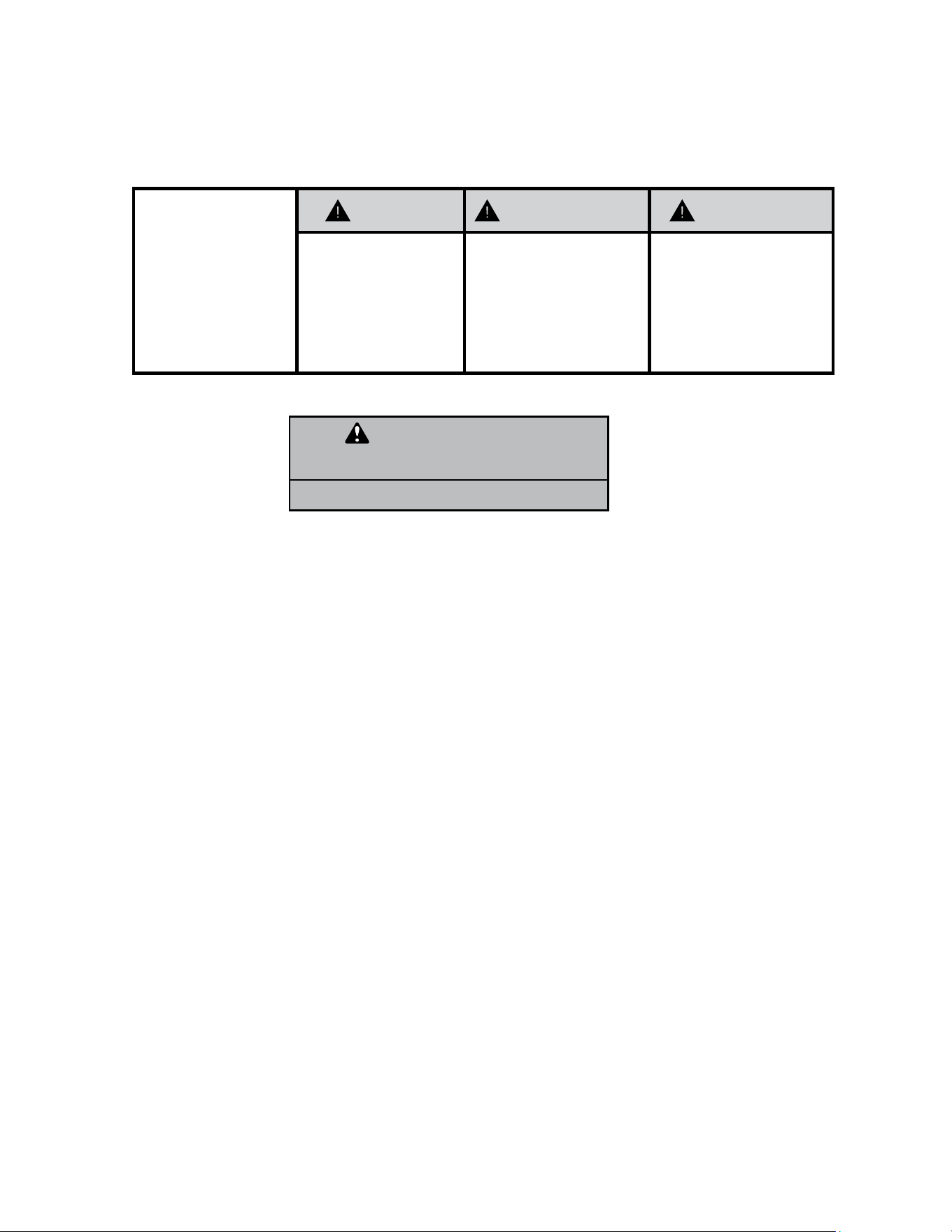
WARNING AVERTISSEMENT ADVERTENCIA
Do not remove, disable
or bypass this unit’s
safety devices. Doing so
may cause re, Doing so
may cause re, injuries,
or death.
Ne pas supprime, désacti-
ver ou contourner cette
l´unité des dispositifs de
sécurité, faire vous risque-
riez de provoquer le feu, les
blessures ou la mort.
No eliminar, desactivar o
pasar por alto los dispositi-
vos de seguridad de la
unidad. Si lo hace podría
producirse fuego, lesiones
o muerte.
ELECTRICAL HAZARDS:
• Unplug and/or disconnect all electrical power to the unit before performing inspections, maintenance, or service.
• Make sure to follow proper lockout/tag out procedures.
• Always work in the company of a qualied assistant if possible.
• Capacitors, even when disconnected from the electrical power source, retain an electrical charge potential capable of causing electric
shock or electrocution.
• Handle, discharge, and test capacitors according to safe, established, standards, and approved procedures.
• Extreme care, proper judgment, and safety procedures must be exercised if it becomes necessary to test or troubleshoot equipment
with the power on to the unit.
• Do not spray water on the air conditioning unit while the power is on.
• Electrical component malfunction caused by water could result in electric shock or other electrically unsafe conditions when the
power is restored and the unit is turned on, even after the exterior is dry.
• Use air conditioner on a single dedicated circuit within the specied amperage rating.
• Use on a properly grounded outlet only.
• Do not cut or modify the power supply cord or remove the ground prong of the plug.
• Never operate the unit on an extension cord.
• Follow all safety precautions and use proper and adequate protective safety aids such as: gloves, goggles, clothing, properly insulated
tools, and testing equipment etc.
• Failure to follow proper safety procedures and/or these warnings can result in serious injury or death.
INTRODUCTION
Personal Injury Or Death Hazards
WARNING
ALWAYS USE INDUSTRY STANDARD PERSONAL
PROTECTIVE EQUIPMENT (PPE)

7 7
• REFRIGERATION SYSTEM REPAIR HAZARDS:
• Use approved standard refrigerant recovering procedures and equipment to relieve high pressure before opening system for repair.
Reference EPA regulations (40 CFR Part 82, Subpart F ) Section 608.
• Do not allow liquid refrigerant to contact skin. Direct contact with liquid refrigerant can result in minor to moderate injury.
• Be extremely careful when using an oxy-acetylene torch. Direct contact with the torch’s ame or hot surfaces can cause serious
burns.
• Make certain to protect personal and surrounding property with re proof materials and have a re extinguisher at hand while using a
torch.
• Provide adequate ventilation to vent off toxic fumes, and work with a qualied assistant whenever possible.
• Always use a pressure regulator when using dry nitrogen to test the sealed refrigeration system for leaks, ushing etc.
• MECHANICAL HAZARDS:
• Extreme care, proper judgment and all safety procedures must be followed when testing, troubleshooting, handling, or working
around unit with moving and/or rotating parts.
• Be careful when, handling and working around exposed edges and corners of the sleeve, chassis, and other unit components
especially the sharp ns of the indoor and outdoor coils.
• Use proper and adequate protective aids such as: gloves, clothing, safety glasses etc.
• Failure to follow proper safety procedures and/or these warnings can result in serious injury or death.
• PROPERTY DAMAGE HAZARDS
• FIRE DAMAGE HAZARDS:
• Read the Installation/Operation Manual for the air conditioning unit prior to operating.
• Use air conditioner on a single dedicated circuit within the specied amperage rating.
• Connect to a properly grounded outlet only.
• Do not remove ground prong of plug.
• Do not cut or modify the power supply cord.
• Do not use extension cords with the unit.
• Be extremely careful when using acetylene torch and protect surrounding property.
• Failure to follow these instructions can result in re and minor to serious property damage.
• WATER DAMAGE HAZARDS:
• Improper installation, maintenance or servicing of the air conditioner unit can result in water damage to personal items or property.
• Insure that the unit has a sufcient pitch to the outside to allow water to drain from the unit.
• Do not drill holes in the bottom of the drain pan or the underside of the unit.
• Failure to follow these instructions can result in damage to the unit and/or minor to serious property damage.
INTRODUCTION
PERSONAL INJURY OR DEATH HAZARDS
8 8
INTRODUCTION
Figure 101 (Model Number Reference Guide)
K C V S 06 B 1 0 A - A
Model Type:
K - Kühl
W - WallMaster
Function:
C- Cool Only
E - Electric Heat
H - Heat Pump
Application:
Q - Q
S - Small
M - Medium
L - Large
T - Through-the-Wall
Approximate
Cooling
BTU/HR
Refrigerant
Type = R-32
Voltage
1- 115 Volts
3- 230 Volts
Heat Strip
1- Straight Cool
2- 1 KW heat strip, nominal
3- 3 KW heat strip, nominal
4- 4 KW heat strip, nominal
5- 5 KW heat strip, nominal
Marketing Suffix
Letter indicates
modification to
existing model
Engineering Rev
Letter indicates an
engineering
modification to an
existing model
Inverter/
Variable
Speed
Compressor
• This service manual is designed to be used in conjunction with the installation and operation manuals provided with each air conditioning system.
• This service manual was written to assist the professional service technician to quickly and accurately diagnose and repair malfunctions.
• Due to continuing research in new energy-saving technology, all information in this manual is subject to change without notice.
• IMPORTANT: It will be necessary for you to accurately identify the unit you are servicing, so you can be certain of a proper diagnosis and repair.
Model Number Reference Guide
YEAR OF MANUFACTURE
23 = 2023 24 = 2024
25 = 2025 26 = 2026
27 = 2027 28 = 2028
MONTH OF MANUFACTURE
01 = JANUARY
02 = FEBRUARY
03 = MARCH
04 = APRIL
05 = MAY
06 = JUNE
07 = JULY
08 = AUGUST
09 = SEPTEMBER
10 = OCTOBER
11 = NOVEMBER
12 = DECEMBER
FACTORY DESIGNATION
M = FRIEDRICH MTY
NUMERIC SEQUENCE
FIRST UNIT OF EACH MONTH = 00001
17 12 M 00001
Figure 102 (Serial Number Reference Guide)
Serial Number Reference Guide
9 9
Figure 104 ( Kuhl Q Model and Serial
Number Location)
FRIEDRICH
AIR CONDITIONING CO.
SAN ANTONIO, TX
MODEL NUMBER
SERIAL NUMBER
VOLTS
60 HZ/ 1PH
115
103 VOLT MIN.
COOLING:
BTU/HR
HEATING:
BTU/HR
7500
EER
9.8
AMPS
6.9
4000
EER
AMPS
11.2
MAX AMPS:
23.5 OZS.
DESIGN PRESSURES
600 PSIG HS
300 PSIG LS
U.S. PATENTS
D458, 229 S
5,634,346
IF CONNECTED TO
A FUSE PROTECTED
CIRCUIT, USE A 12 A
TIME DELAY FUSE
LISTED 183H
AALY00219
EQ08N11-A
ROOM AIR
CONDITIONER
FRIEDRICH
Assembled in Mexico
MODEL NUMBER
AIR CONDITIONING CO.
SAN ANTONIO, TX
SERIAL NUMBER
VOLTS
60 HZ/ 1PH
AALY002024
KCVQ08B10A
SYSTEM
MODE
FAN
Figure 103 (Kuhl Model and Serial Number Location)
INTRODUCTION
Model And Serial Number Location
FRIEDRICH
Assembled in Mexico
MODEL NUMBER
AIR CONDITIONING CO.
SAN ANTONIO, TX
SERIAL NUMBER
VOLTS
60 HZ/ 1PH
AALY002024
WHVT12B33A
Figure 105 (Wallmaster Model and Serial Number Location)
IMPORTANT: It will be necessary for you to accurately identify the unit you are servicing, so you can be certain of a proper diagnosis and repair.
MODEL NUMBER
KCVS12B30A
SERIAL NUMBER
LICY00008
AIR CONDITIONING CO.
SAN ANTONIO, TEXAS
ASSEMBLED IN MEXICO
INTRODUCTION
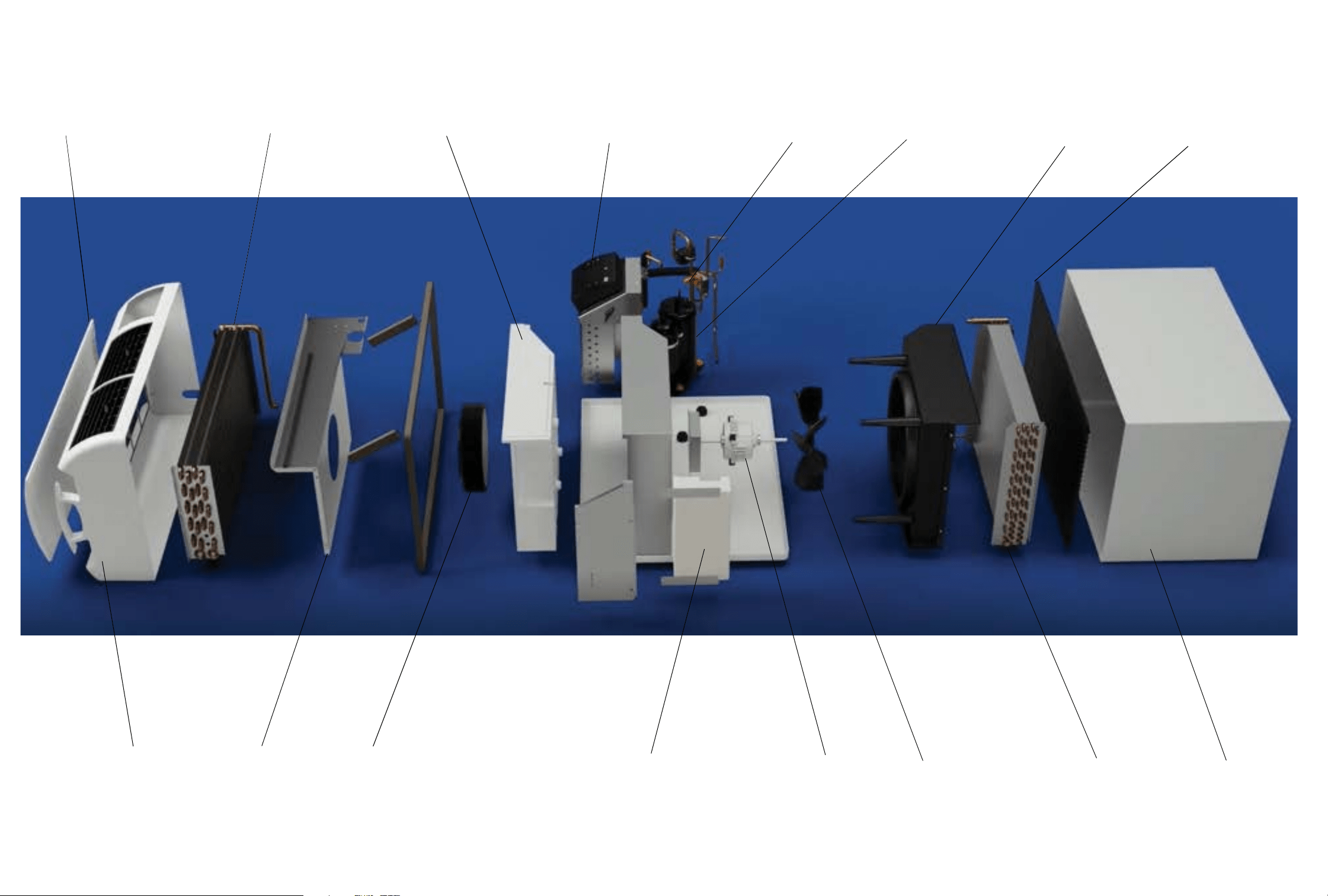
Component Identification- Wallmaster
Intake Grill
Evaporator
Decorative Front
Blower Front
Blower Wheel
Blower Wheel Scroll
User Interface
Reversing Valve
Compressor
Fan Shroud
Exterior Grill
Wall Sleeve
Condenser
Fan Blade
Fan Motor
Main PCB Assembly
Figure 107
12 12
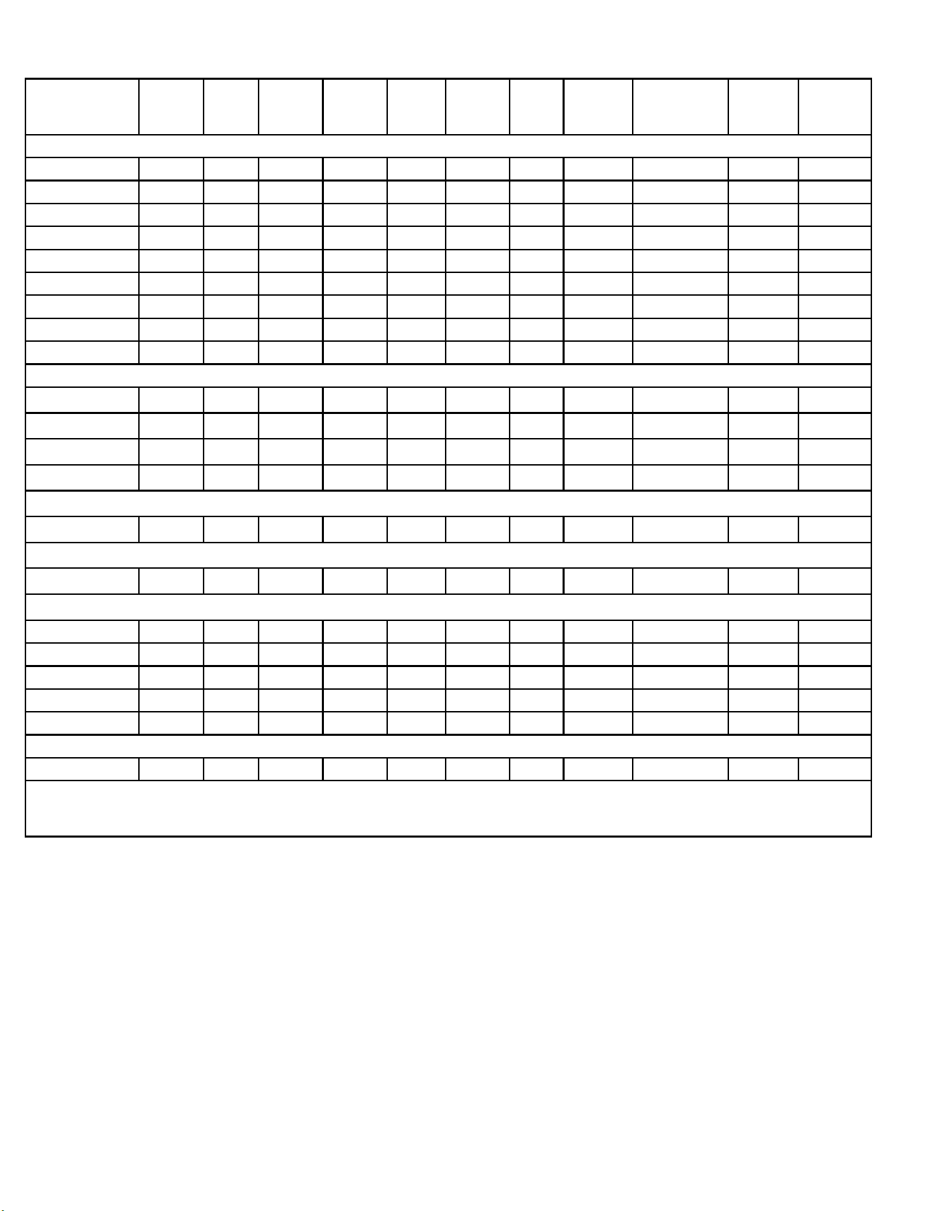
Figure 201(Specications)
Model Cooling
Btu
Heating
Btu
Volts Cooling
Amps
Cooling
Watts
Heating
Amps
Heating
Watts
EER REFRIGERANT
CHARGE (OZ.)
CEER Estimated
yearly En-
ergy Cost
Kuhl Cooling Only Units
KCVS08B10A
KCVS12B10A
KCVM14B10A
KCVS12B30A
KCVS16B30A
KCVM18B30A
KCVM24B30A,
KCVL28B30A,
KCVL36B30A
Kuhl Heat Pump Units
KHVS10B11A,
KHVS12B33A,
KHVM24B34A
KHVL28B35A
Kuhl Q Cooling Only Units
KCVQ08B10A
Kuhl Q Heat Pump Units
KHVQ10B11A
Wallmaster Cooling Only Units
WCVT10B10A
WCVT12B10A
WCVT10B30A
WCVT12B30A
WCTV16B30A
Wallmaster Heat Pump Units
WHVT14B33A
Friedrich room air conditioners are designed to operate in cooling mode with outdoor temperatures from 60˚F to 115˚F.
**Rating Conditions: 80 degrees F, room air temp. & 50% relative humidity, with 95 degree F, outside air temp & 40% relative humidity, all systems
use R-32. Test done at highest unit fan speed.
SPECIFICATIONS
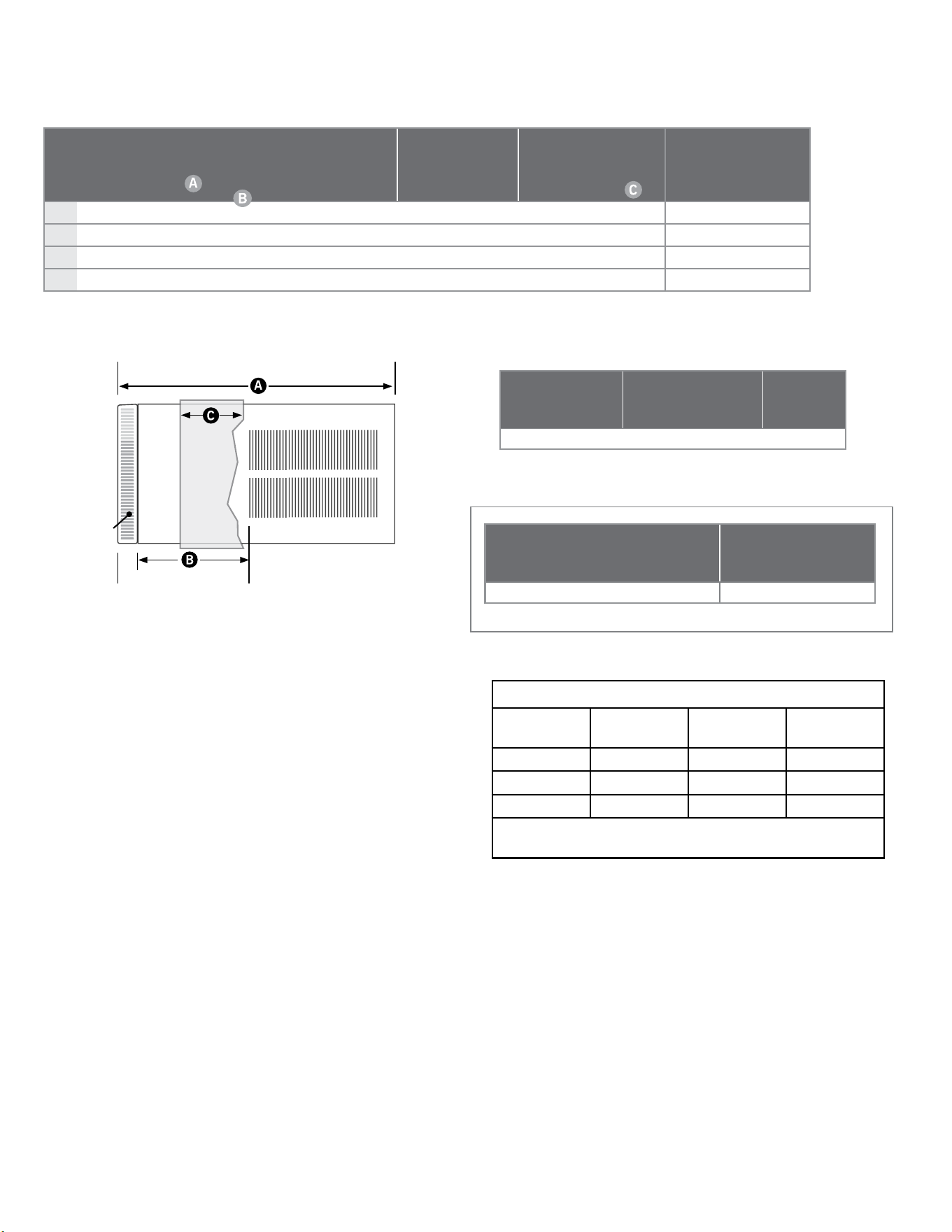
13 13
Sleeve
Height
Inches
Width
Inches
Depth
with Front
Inches
Shell
Depth
to Louvers
Inches
Minimum
Extension
Into Room*
Inches
Minimum
Extension
Outside
* Inches
Window Width
INCHES
In-wall Installation
Finished Hole Inches
Carton Dimensions
Inches
Minimum** Maximum Height Width
Max. Depth
Height Width Depth
S
15
15
/16"
25
15
/16" 29"
8
3
/4"
5
3
/4"
16
15
/16"
27
3
/8" 42"
16
3
/16" 26
3
/16"
7
3
/8" 19" 29" 34
1
/2"
M
17
15
/16"
25
15
/16" 29"
8
3
/4"
5
3
/4" 16
15
/16"
27
3
/8" 42"
18
3
/16"
26
3
/16"
7
3
/8" 21" 29"
34
1
/2"
L
20
3
/
16
" 28" 35
1
/
2
" 16
1
/
2
" 5
3
/
8
" 18
15
/
16
" 29
7
/
8
" 42" 20
3
/
8
" 28
1
/
4
" 15
1
/
8
" 24
1
/
2
" 31
5
/
8
" 38
7
/
8
"
Q
14
1
/4"
19
3
/4" 21
3
/8"
8
1
/2"
5
1
/2"
10
3
/4" 22" 42"
14
1
/2" 20"
8
1
/2"
18
3
/4" 22"
25
1
/2"
SPECIFICATIONS
Dimensions
FRONT
SIDE VIEW
SLEEVE DIMENSIONS DRAWING
Installation Clearances
Improper installation of the Air Conditioner can cause poor performance and premature wear of the unit.
Ensure that the KUHL unit is installed with proper clearances as described below.
Ensure no obstructions or enclosures are within clearances limits to allow for proper airow.
Ensure no open ames, or surfaces that will exceed 1000 degrees Fahrenheit are within clearances limits.
Clearances
Top and Bottom of Unit - One (1) foot
Sides of Unit - One (1) foot
Front of Unit - Three (3) feet
Rear of Unit - Three (3) feet
Figure 202 (Kuhl Dimensions)
Figure 203 (Kuhl Sleeve Dimensions)
Height W idth Depth
Height
of Front
Width of
Front
Depth
with
Front
Minimum
Extension Into
Room with
Front
15 ¾" 26 ½" 21" 17 ¼" 27 ½" 23 ¼" 7 ½"
Height W i d t h Depth
Depth
with
Front
Minimum
Extension
Outside
Thru-the-wall
Finished Hole
Height Width Max. Depth
16 ¾" 27" 16 ¾" 24 ¼"
9
/
16
" 17 ¼" 27 ¼" 15
5
/
16
"
Figure 204 (Wallmaster Chassis Dimensions)
Figure 205 (Wallmaster WSE Sleeve Dimensions)
Sleeve Dimensions
Freiedrich
WSE Sleeve
Fedders A
Sleeve
Fedders B
Sleeve*
Height 16
3/4”
16
3/4
” 16
3/4
”
Width 27” 27” 27”
Depth 16
3/4”
16
3/4
” 19
3/4
”
*Installation in a Fedders B sleeve requires a bafe adapter
kit-BAK
Figure 206 (Wallmaster WSE Sleeve Dimensions)
14 14
SPECIFICATIONS
Electrical Data
WARNING
ELECTRIC SHOCK HAZARD
Turn off electric power before service or
installation.
All electrical connections and wiring MUST be
the National Electrical Code and all local codes
which have jurisdiction.
Failure to do so can result in personal injury or
death.
NOTICE
FIRE HAZARD
electrically unsafe conditions which could cause moderate
or serious property damage.
Read, understand and follow the above warning.
Wire Size - Use ONLY wiring size recommended by the National Electric Code (NEC) for single outlet branch circuit.
Fuse/ Circuit Breaker - Use ONLY the correct HACR type and size fuse/circuit breaker. Read electrical ratings on unit’s rating plate.
Proper circuit protection is the responsibility of the homeowner.
Grounding - Unit MUST be grounded from branch circuit through service cord to unit, or through separate ground wire provided on
permanently connected units. Be sure that branch circuit or general purpose outlet is grounded.
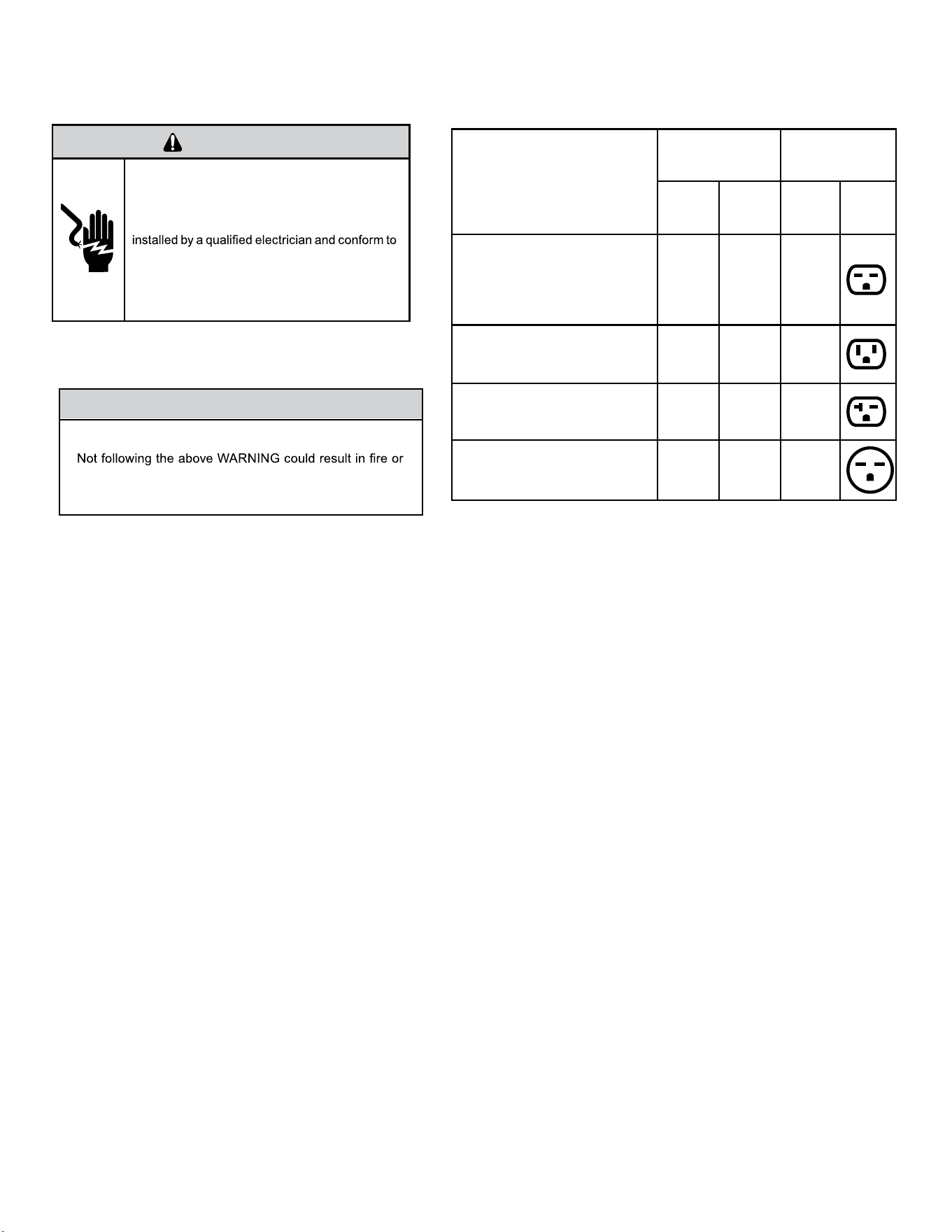
Receptacle - The eld supplied outlet must match plug on service cord and be within reach of service cord. Do NOT alter the service
cord or plug. Do NOT use an extension cord. Refer to the table above for proper receptacle and fuse type.
Figure 207 (Circuit Breaker / Plug / Receptacle / Cord Rating)
MODEL
CIRCUIT RATING
OR TIME DELAY
FUSE
REQUIRED
WALL
RECEPTACLE
AMP VOLT
NEMA
NO.
KCVS08B10A, KCVS12B10A,
KCVM14B10A,
KHVS10B11A,KCVQ08B10A,
KHVQ10B11A WCVT10B10A,
WCVT12B10A
15 125 5-15R
KCVS12B30A, KCVS16B30A,
KCVM18B30A WCVT10B30A,
WCVT12B30A WCVT16B30A
15 250 6-15R
KHVS12B33A, KCVM24B30A,
KCVL28B30A , KEVS16B33A,
WHVT14B33A
20 250 6-20R
KHVM24B30A, KHVL28B35A,
KCVL36B30A, KEVL36B35A
30 250 6-30R
15 15
WARNING
Electrical Shock Hazard
Make sure your electrical receptacle
has the same conguration as your air
conditioner’s plug. If different, consult
a Licensed Electrician.
Do not use plug adapters.
Do not use an extension cord.
Do not remove ground prong. Always
plug into a grounded 3 prong outlet.
Failure to follow these instructions
can result in death, re, or electrical
shock.
Make sure the wiring is adequate for your unit.
If you have fuses, they should be of the time delay type. Before you install or relocate this unit, be sure that the
amperage rating of the circuit breaker or time delay fuse does not exceed the amp rating listed in Table 206.
DO NOT use an extension cord.
The cord provided will carry the proper amount of electrical power to the unit; an extension cord may not.
Make sure that the receptacle is compatible with the air conditioner cord plug provided.
Proper grounding must be maintained at all times. Two prong receptacles must be replaced with a grounded receptacle by a certied electrician.
The grounded receptacle should meet all national and local codes and ordinances. You must use the three prong plug
furnished with the air conditioner. Under no circumstances should you remove the ground prong from the plug.
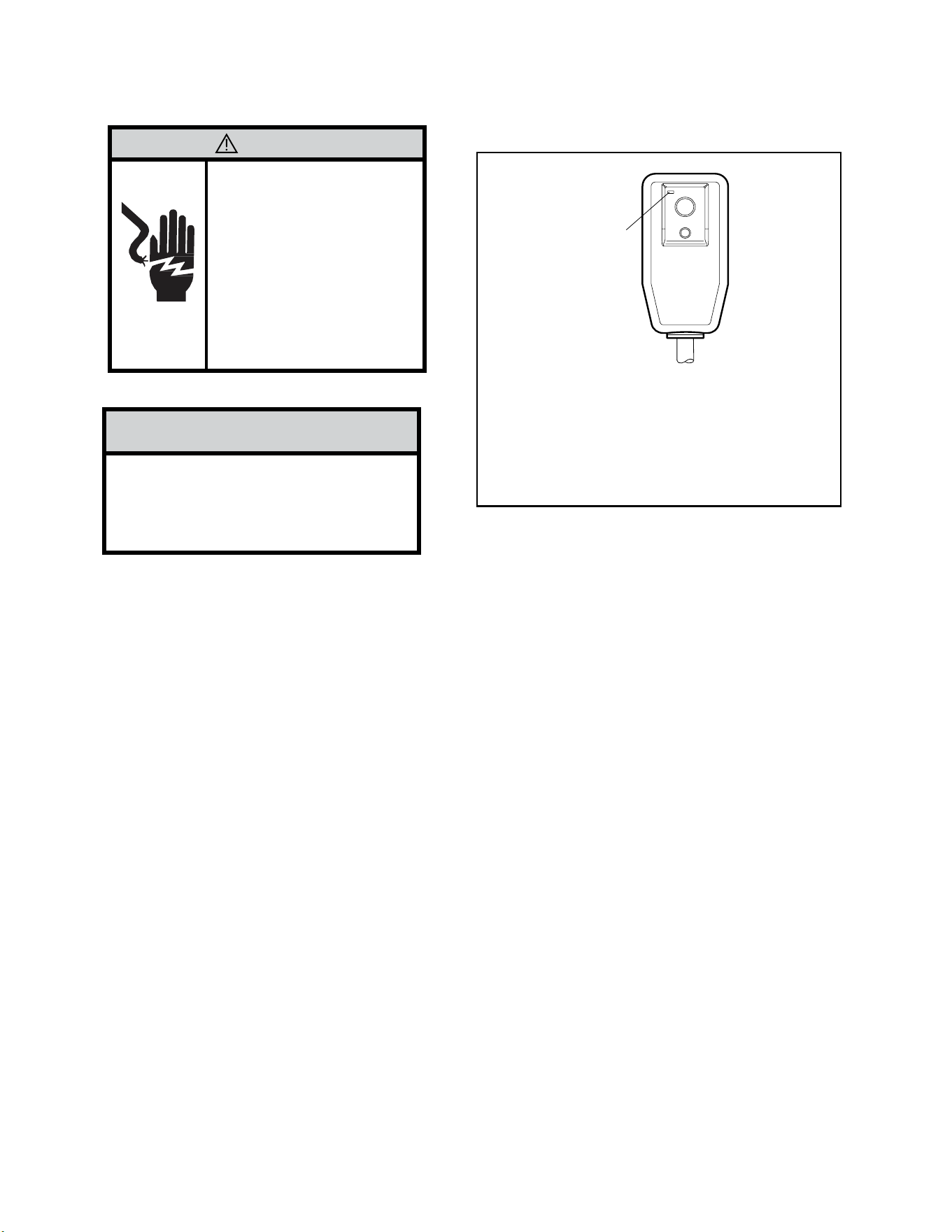
Test the power cord.
All Friedrich room air conditioners are shipped from the factory with a Leakage Current Detection Interrupter (LCDI) equipped power
cord. The LCDI device on the end of the cord meets the UL and NEC requirements for cord connected air conditioners.
To test your power supply cord:
1. Plug power supply cord into a grounded 3 prong outlet.
2. Press RESET (see Figure 207).
3. Press TEST, listen for click; the RESET button trips and pops out.
4. Press and release RESET (Listen for click; RESET button latches and remains in). Check that the green LED light is on. The power cord is ready. for use.
Once plugged in, the unit will operate normally without the need to reset the LCDI device. If the LCDI device fails to trip when tested or if the power supply
cord is damaged, it must be replaced with a new power supply cord from the manufacturer.
NOTICE
Do not use the LCDI device as an ON/OFF
switch.
Failure to adhere to this precaution may
cause premature equipment malfunction.
WARNING:
TEST BEFORE EACH USE!
1. PRESS RESET BUTTON.
2. PLUG LCDI INTO POWER
RECEPTACLE.
3. PRESS TEST BUTTON,
RESET BUTTON SHOULD
POP UP.
4. PRESS RESET BUTTON
FOR USE.
DO NOT USE IF ABOVE
TEST FAILS.
RESET
TEST
Green LED
Indicator
Light
(Illuminated
when ready
for use)
SPECIFICATIONS
Electrical Data -Power Cord
Figure 208 (LCDI Power Cord)
16 16
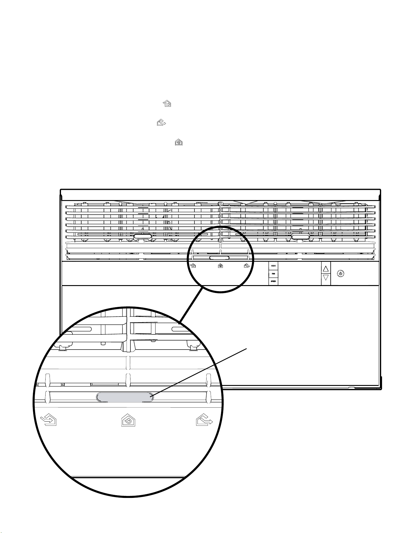
The airow path may be adjusted to distribute air independently from the left or right side of the discharge opening. Each of the banks of louvers can
be directed left, right, up, or down in order to achieve the most optimum airow positioning.
To adjust airow direction, grab the lever in the center of the louver bank and move it in the direction that you would like the air to be directed. Please
note that it is normal that airow may be stronger out of one side of the louvers than the other.
Fresh air and exhaust control
Your air conditioner has the ability to bring fresh air into the room or exhaust stale air out of the room. The control slide is found on the upper part of the
unit (see Figure 301).
TO BRING IN FRESH AIR – Move the lever to the Fresh Air
position which allows outside air to enter the room. This is useful in fall and spring as a
means of bringing in fresh outside air when using FAN ONLY. It can also be used in the summer with the compressor in the Cooling Mode if you wish.
TO EXHAUST INDOOR AIR – Move the lever to the Exhaust
position. This will allow stale air to be expelled to the outside of the dwelling. This is espe-
cially handy in the spring or fall when indoor air tends to get stale, or after a social gathering involving smokers, or to remove cooking odors.
BEST PERFORMANCE – Move the lever to the Re-Circulate Position.
This is the most efcient mode for cooling and heating. In this mode the unit will not
bring air in or exhaust air.
OPERATION
Airow Selection and Adjustment -Kuhl
Air Lever
Figure 301.1 (Airow Selection And Adjustment)
17 17
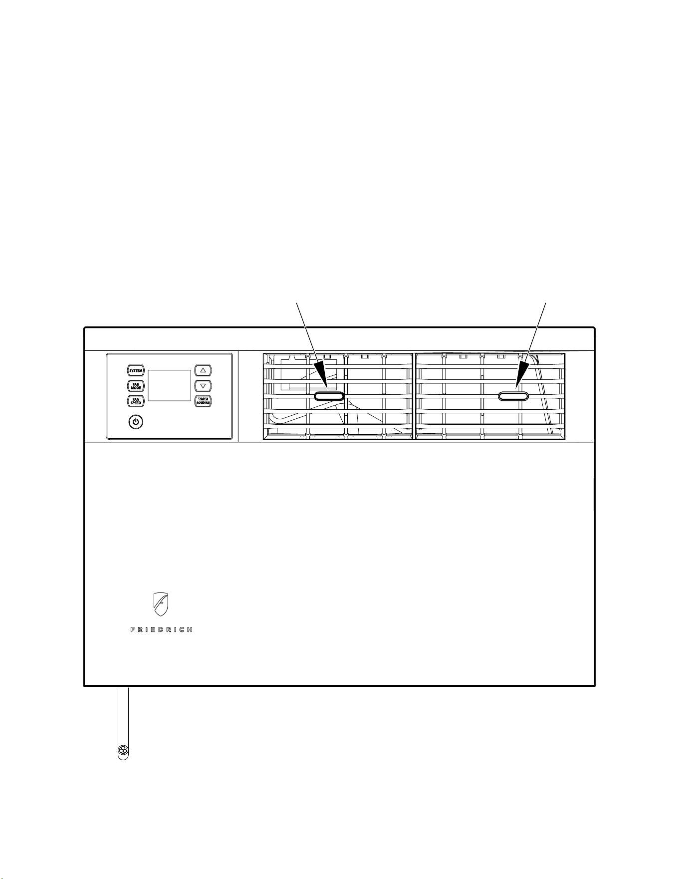
The airow path may be adjusted to distribute air independently from the left or right side of the discharge opening. Each of the banks of louvers can
be directed left, right, up, or down in order to achieve the most optimum airow positioning.
To adjust airow direction, grab the lever in the center of the louver bank and move it in the direction that you would like the air to be directed. Please
note that it is normal that airow may be stronger out of one side of the louvers than the other.
Figure 301.2 (Airow Adjustment)
LEFT AIRFLOW
LEVER
RIGHT AIRFLOW
LEVER
OPERATION
Airow Selection and Adjustment -Kuhl Q
18 18
The airow path may be adjusted to distribute air independently from the left or right side of the discharge opening. Each of the banks of louvers can
be directed left, right, up, or down in order to achieve the most optimum airow positioning.
To adjust airow direction left or right, grab the lever in the center of the louver bank and move it in the direction that you would like the air to be
directed. To adjust the airow up or down, rotate the entire vent to the desired position Please note that it is normal that airow may be stronger out of
one side of the louvers than the other.
OPERATION
Airow Selection and Adjustment -Wallmaster
Figure 303 (Airow Selection And Adjustment)
Left and right
Adjustment
Up and Down
Adjustment
19 19
OPERATION
User Interface-Kuhl
All of the control panel function buttons and mode icons can be viewed in Figures 302 and 303.
Power On – Press the button to turn on the air conditioner. The power button illuminates to indicate that the power is on. The backlight on the power
switch will automatically turn off after 20 seconds of inactivity. The remote control can also be used to turn power ON / OFF (see Remote Control).
Display – The display is a high efciency LCD with a built-in backlight. After 20 seconds of inactivity, the display switches off. Touching any button
automatically changes the display to full brightness.
There are three control push buttons on each side of the display.
MODE
Cycles between AUTO,
HEAT, COOL, or FAN
ONLY
CONTROL PANEL
TEMPERATURE
INCREMENT UP
AND DOWN
ON / OFF
Turns unit on / off
IR WINDOW
Do not block
FAN
Sets fan to either:
-automatically cycle
-continuously run
SPEED
Sets fan speed
LOW, MED, HIGH, OR MAX
(Actual settings are model
dependent)
DISPLAY
Figure 304
Figure 303
Unit
Mode
Display
Disconnected From
Power Board
Control
Locked
Wi-Fi Operating
State
2 Digit Display
Shows Settings for:
-Set Point
(Temperature)
-Clock (AM/PM)
Filter
Check /
Clean
Timer/
Schedule
Shows
On / Off
20 20
OPERATION
User Interface - Kuhl Q
All of the control panel function buttons and mode icons can be viewed in Figure 305.
Power On – Press the button to turn on the air conditioner. The power button illuminates to indicate that the power is on. The backlight on the power
switch will automatically turn off after 20 seconds of inactivity. The remote control can also be used to turn power ON / OFF (see Remote Control).
Display – The display is a high efciency LCD with a built-in backlight. After 20 seconds of inactivity, the display switches off. Touching any button
automatically changes the display to full brightness.
There are three control push buttons on each side of the display.
-AUTO-
Automatically switches
between cool & heat
CONTROL
LOCKED
WI-FI OPERATING
STATE
TEMPERATURE
UP
TEMPERATURE
DOWN
2 DIGIT DISPLAY
Shows Setting for:
- Set Point (Temperature)
- Clock (AM/PM)
FILTER
Check / clean
FAN SPEED
Sets fan speed:
LOW, MED, HIGH,
OR MAX
(Actual settings are
model dependant)
FAN
Sets fan to either:
- Automatically cycle
- Continuously run
COOL HEAT FAN ONLY DISCONNECTED FROM
POWER BOARD
MODE
Cycles between
COOL, HEAT, FAN
ONLY or -AUTO-
(if equipped)
ON / OFF
Turns unit on/off
TIMER
shows on or off
Figure 305 (Control Panel and Display)
21 21
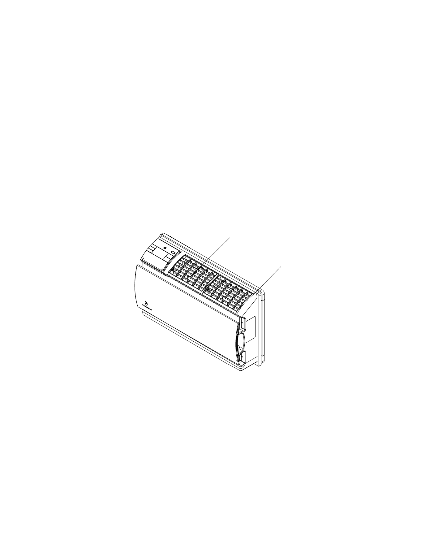
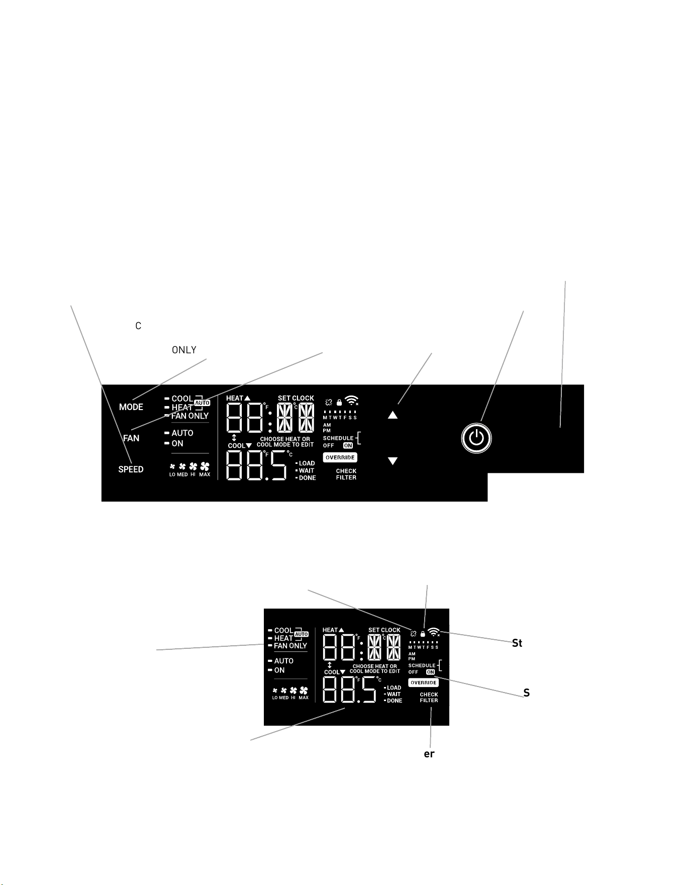
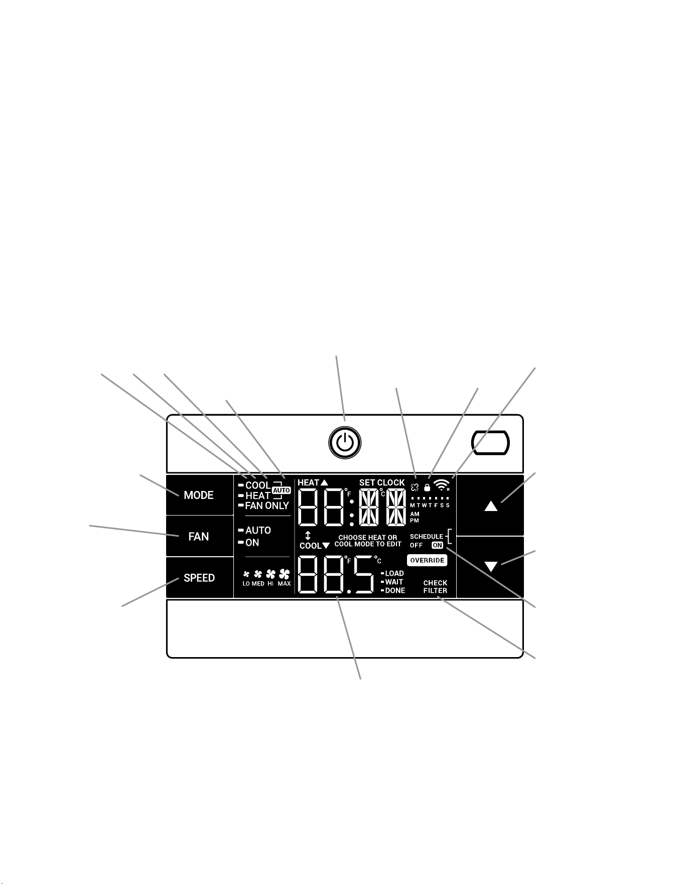
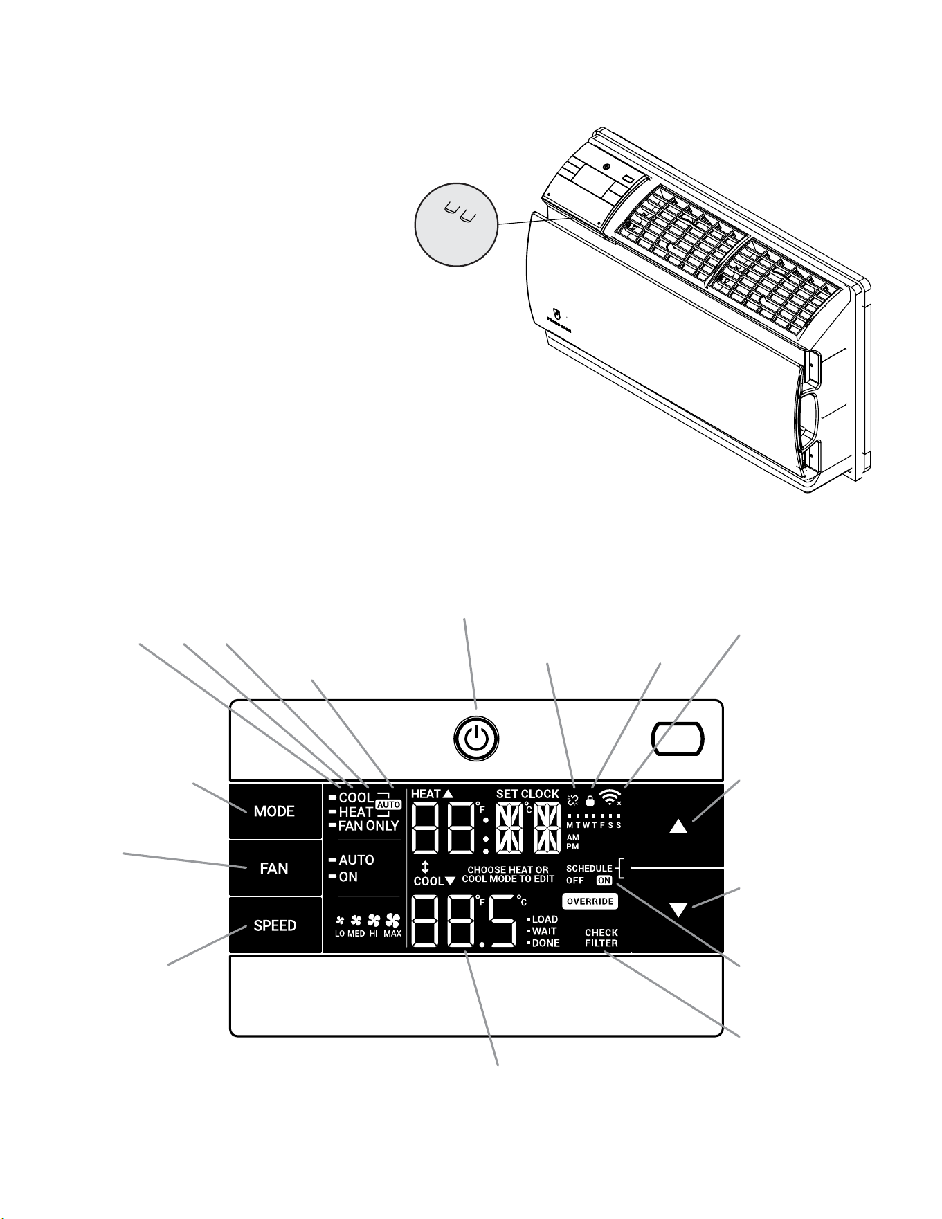
OPERATION
User Interface- Wallmaster
All of the control panel function buttons and mode icons can be
viewed in Figures 307.
Power On – Press the button to turn on the air conditioner. The
power button illuminates to indicate that the power is on. The
backlight on the power switch will automatically turn off after
20 seconds of inactivity. The remote control can also be used to
turn power ON / OFF (see Remote Control).
Display – The display is a high efciency LCD with a built-in
backlight. After 20 seconds of inactivity, the display switches off.
Touching any button automatically changes the display to full
brightness.
There are three control push buttons on each side of the display.
CONTROL PANEL AND DISPLAY
Figure 306 (Wallmaster Menu Buttons)
-AUTO-
Automatically switches
between cool & heat
CONTROL
LOCKED
WI-FI OPERATING
STATE
TEMPERATURE
UP
TEMPERATURE
DOWN
2 DIGIT DISPLAY
Shows Setting for:
- Set Point (Temperature)
- Clock (AM/PM)
FILTER
Check / clean
FAN SPEED
Sets fan speed:
LOW, MED, HIGH,
or MAX (Selected
Models Only)
FAN
Sets fan to either:
- Automatically cycle
- Continuously run
COOL HEAT FAN ONLY DISCONNECTED FROM
POWER BOARD
MODE
Cycles between
COOL, HEAT, FAN
ONLY or -AUTO-
(if equipped)
ON / OFF
Turns unit on/off
TIMER
shows on or off
MENU RETURN
Figure 307 (Display Panel)
22 22
OPERATION
User Interface - All Models
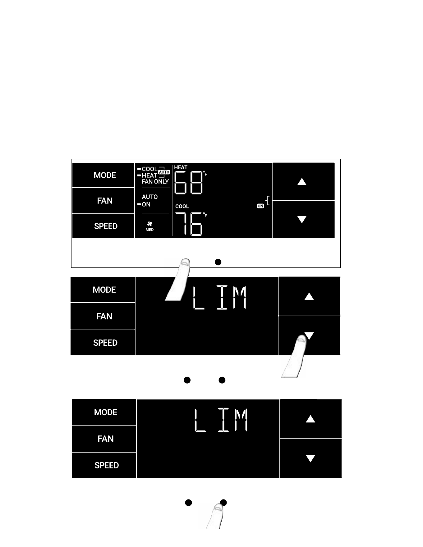
Accessing Sub-Menus
The MENU button accesses the sub-menu.
Figure 308
MENU RETURN
Press the Menu Button to enter the Menu. See Figure 308.
The arrow buttons navigate the 6 menu options. See Figure 309
– LIM – LOCK
– TM – CnCT
– F-C – diAG
The return button exits the menu. See Figure 310.
Figure 309
Figure 310
MENU
RETURN
MENU
RETURN
23 23
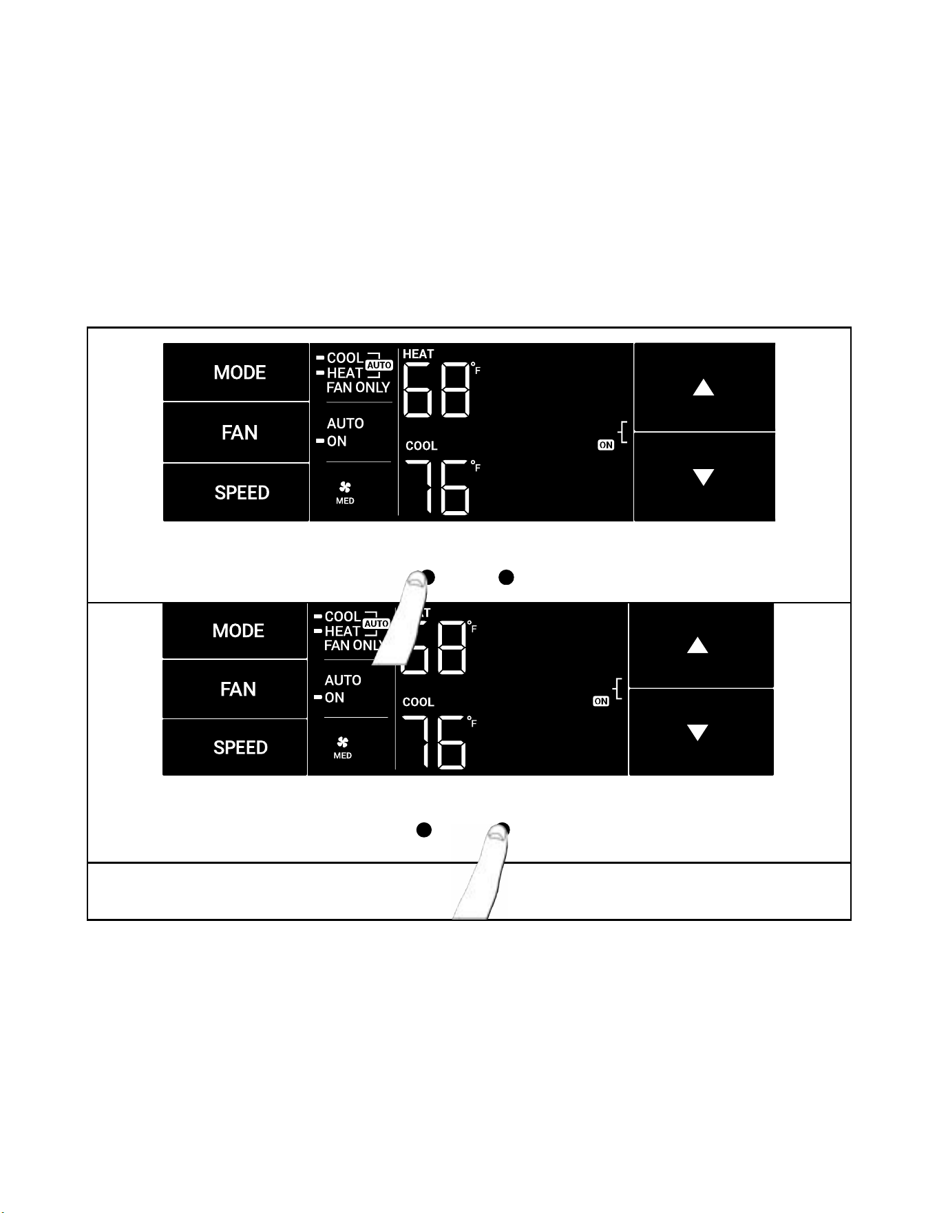
Navigating Inside the Sub-Menus
The MENU button moves you forward through the sub-menu. See Figure 311
The return button moves you backward once inside the LIM and TM menus. See Figure 312.
Figure 311
MENU RETURN
Figure 312
MENU RETURN
OPERATION
User Interface - All Models
24 24
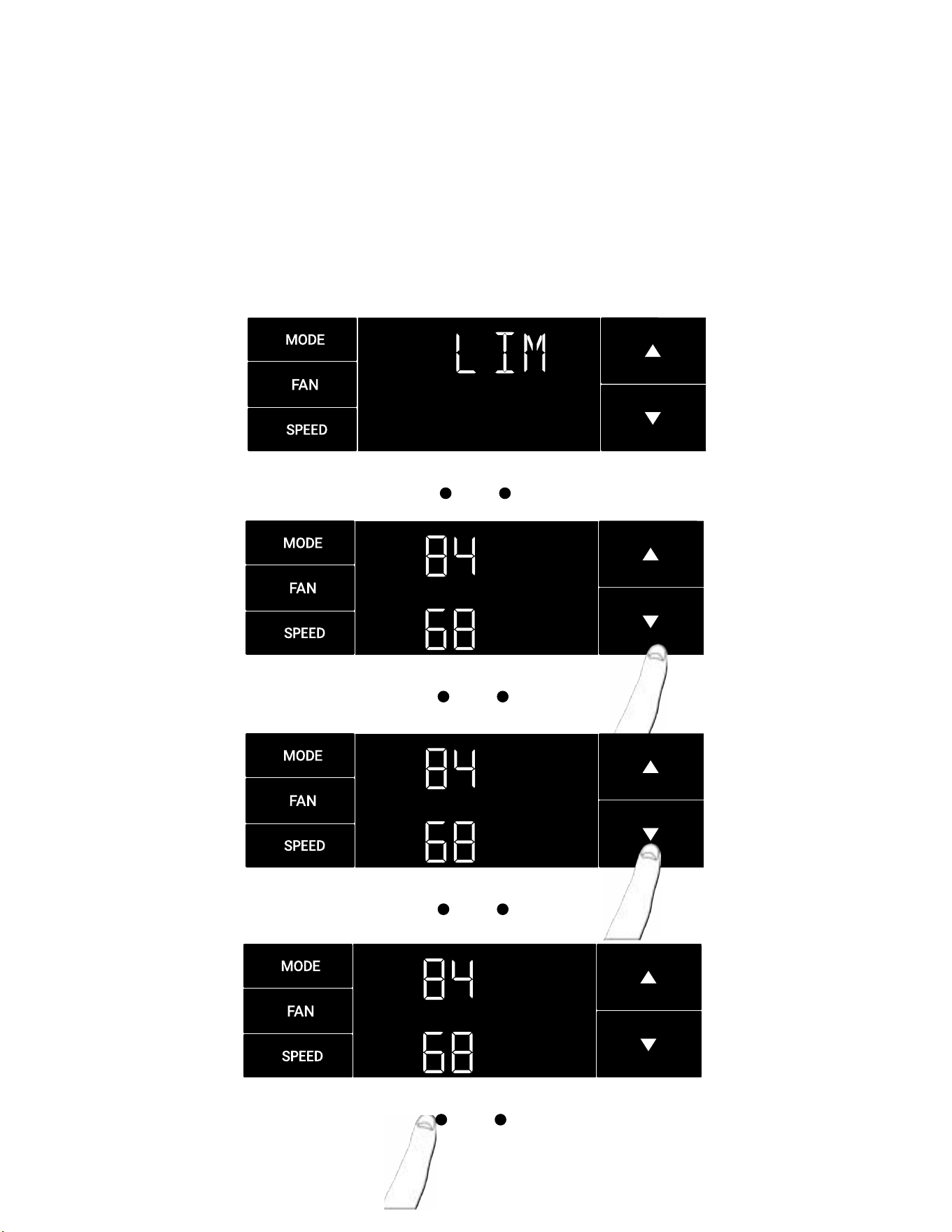
The LIM Menu (LIMIT)
This is the limit menu. See Figure 313.
Upon entering the menu, the rst option will be to set the lower set-point limit using the arrow buttons. See Figure 314.
Then you can set the higher set-point limit using the arrow buttons. See Figure 315.
Pressing the menu button completes the limit setting. See Figure 316.
Figure 313
MENU
RETURN
Figure 314
MENU
RETURN
Figure 315
Figure 316
MENU
RETURN
MENU
RETURN
OPERATION
User Interface - All Models
25 25
MENU RETURN
MENU RETURN
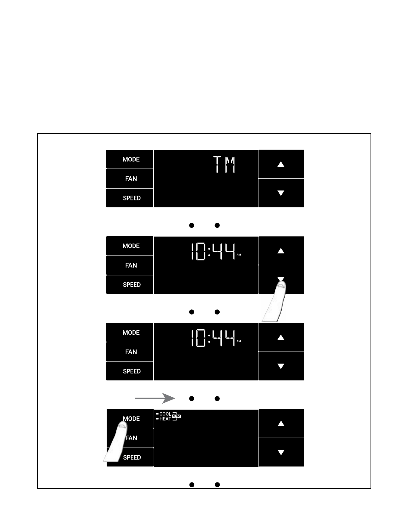
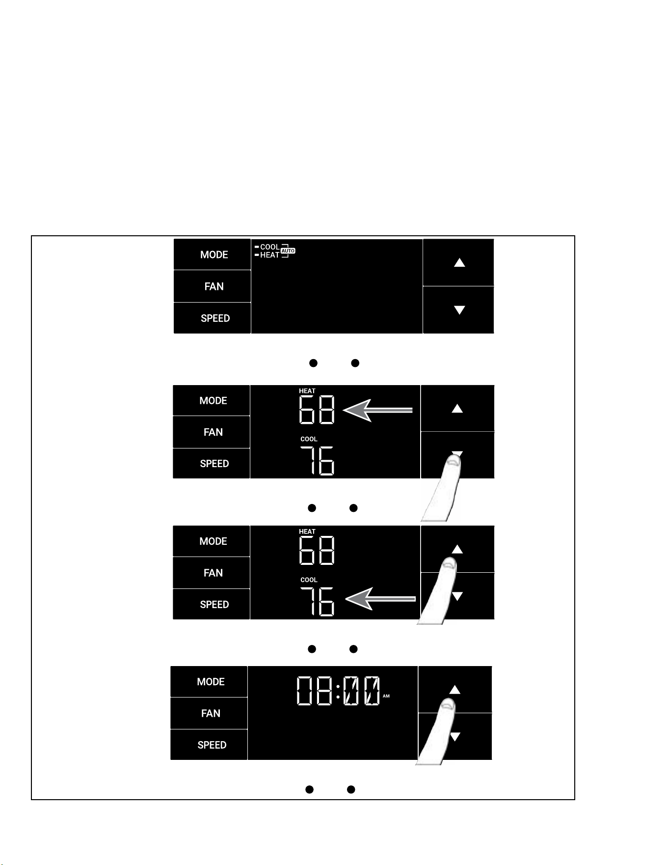
The TM Menu (Timer)
This is the TM menu used to set a timer. See Figure 317.
In the menu, you set the current time using the arrow buttons. See Figure 318. (Note: These two “set clock” steps will be skipped if the unit is already
connected to Wi-Fi.)
First, set the hour.
Using the MENU button, you switch to the minutes and complete setting the time. See Figure 319.
You select your mode. Either cool, heat, or auto. Toggle these using the mode button. See Figure 320. (Note: cooling-only models skip this step.)
The process is the same for all three modes. Auto mode will be shown as the example.
Figure 317
MENU
RETURN
Figure 318
MENU RETURN
Figure 319
Figure 320
OPERATION
User Interface - All Models
26 26
MENU RETURN
MENU RETURN
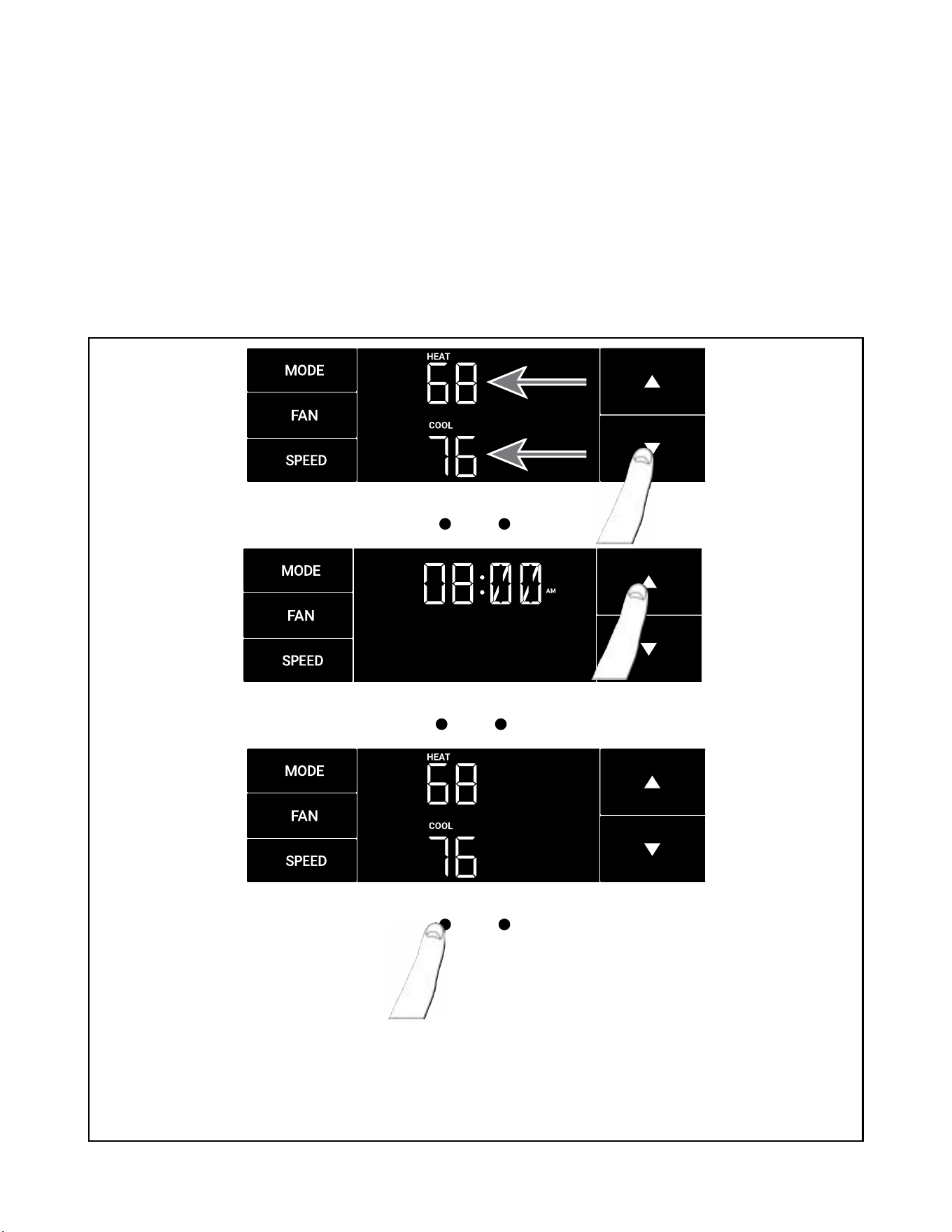
The TM Menu (Timer) continued
Auto mode selected. See Figure 321.
Set the cool set-point for your rst timer period using the arrow buttons. The cooling mode timer only sets the cool set-point. See Figure 322.
Next, set the heat set-point for your rst timer period. The heating mode timer only sets the heat set-point. See Figure 323.
Note: The auto mode timer sets both the cool and heat set-point.
Set the time to start the rst timer period. See Figure 324.
Figure 321
Figure 322
MENU RETURN
Figure 323
Figure 324
MENU RETURN
OPERATION
User Interface - All Models
27 27
MENU RETURN
The TM Menu (Timer) continued
Set the cool set-point for the second scheduled timer. See Figure 325.
Set the heat set-point for the second timer.
Set the time to start the second timer period. See Figure 326.
Press the MENU button to complete the time timer setup.
See Figure 327
Figure 325
MENU RETURN
Figure 326
Figure 327
MENU RETURN
OPERATION
User Interface - All Models
28 28
MENU RETURN
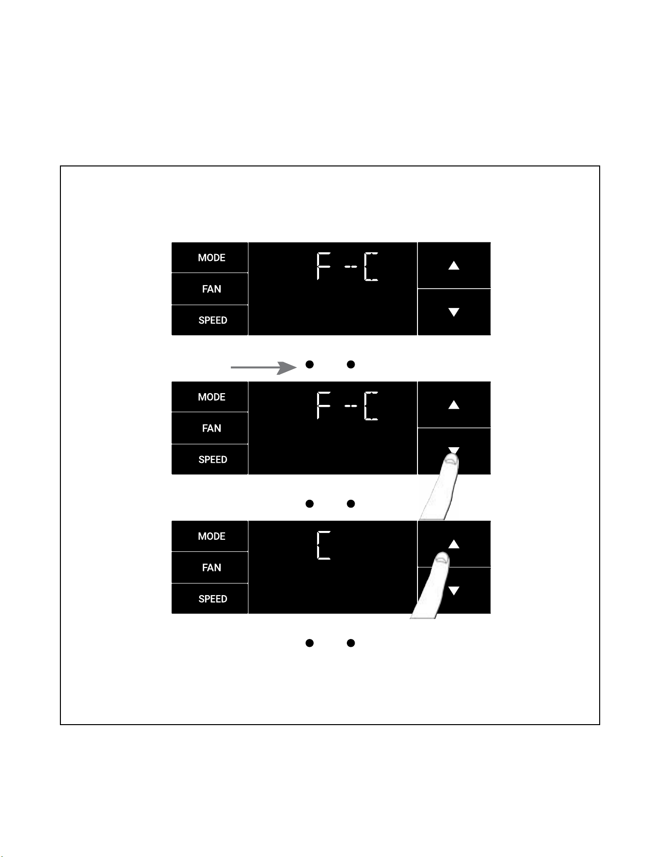
The F-C Menu (Fahrenheit/ Celsius)
This menu is used to toggle between Fahrenheit and Celsius. See Figure 328.
Using the arrow buttons on the right side switches it from Fahrenheit to Celsius. See Figures 329 and 330.
Figure 328
MENU RETURN
Figure 329
MENU RETURN
Figure 330
OPERATION
User Interface - All Models
29 29
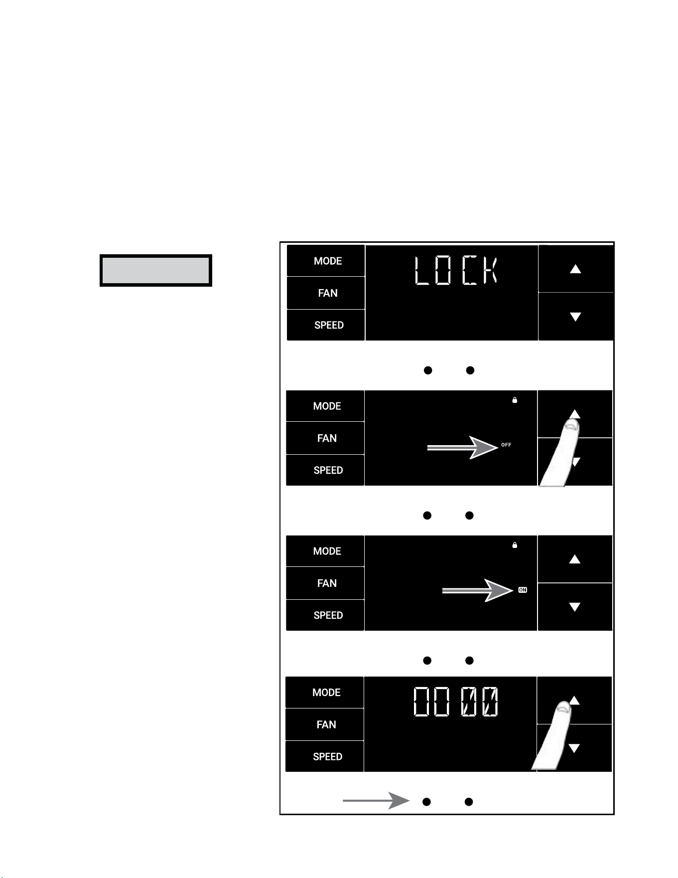
The Lock Menu
This menu is used to lock the settings with a four(4) digit passcode.
This is the Lock Menu. See Figure 331.
The menu lock default is off. Use the arrows to toggle between off and on. See Figure 332.
This is LOCK on. See Figure 333.
Set the rst digit of the password using the arrow buttons. Use the menu button to proceed to the next digit. See Figure 334
Repeat the previous step for the remaining three(3) digits.
Press the menu button to complete the lock setting process..
Figure 331
MENU RETURN
Figure 332
MENU RETURN
Figure 333
MENU RETURN
Figure 334
MENU RETURN
NOTICE
Be Sure to write down your
passcode if you activate this
feature.
___ ___ ___ ___
Please contact Technical Support if
you have lost your lock code.
1-800-541-6645
OPERATION
User Interface - All Models

30 30
The Lock Menu continued
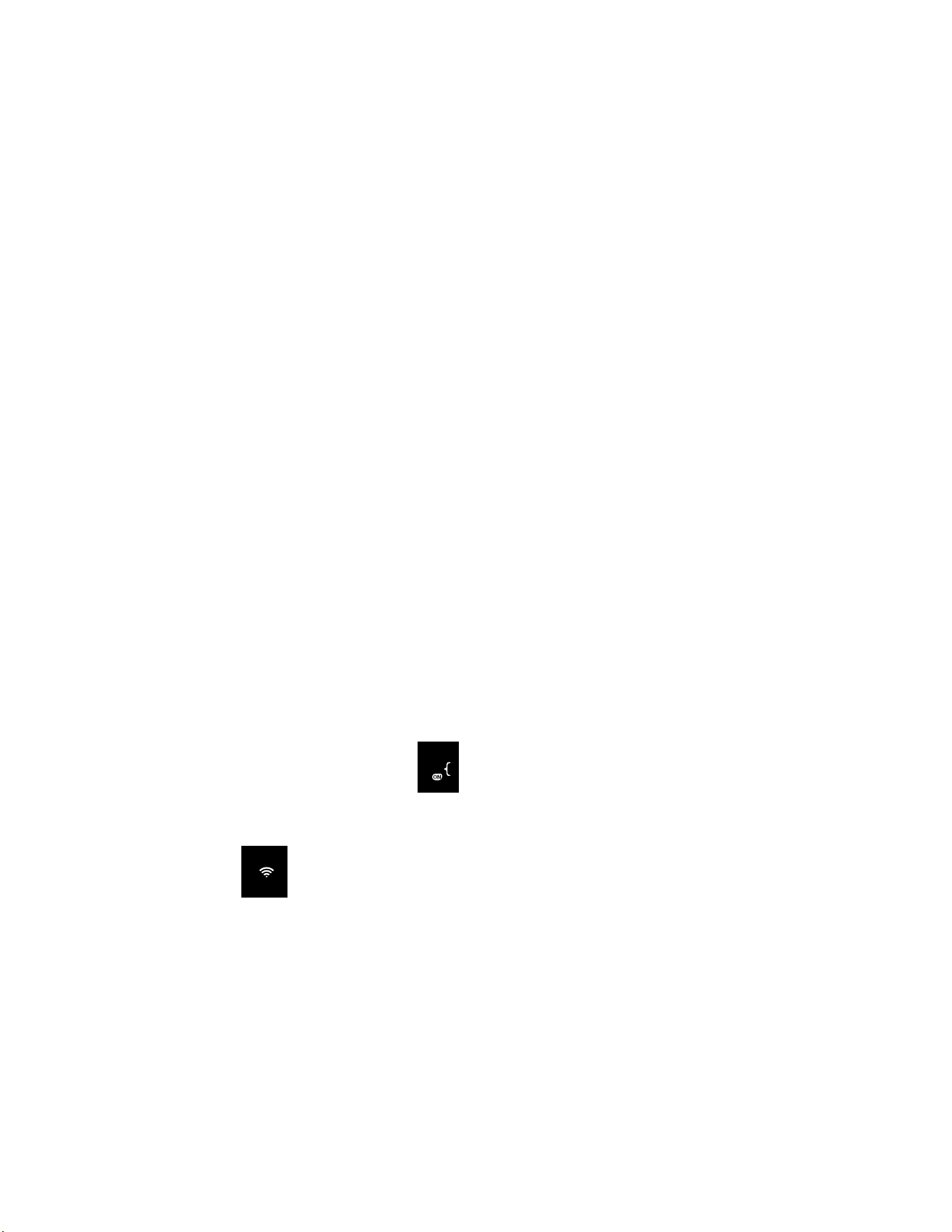
The ON on the right side of the display shows the lock function is active. To go back into the menu, select the menu button again. See Figure 335.
Enter the password in the same manner it was created. See Figure 336.
Entering the correct password will give the user access to all of the sub-menus. See Figure 337.
Accessing the lock menu will allow you to toggle lock OFF if needed. See Figure 338.
Figure 335
MENU RETURN
Figure 336
MENU RETURN
Figure 337
MENU RETURN
Figure 338
MENU RETURN
OPERATION
User Interface - All Models
31 31
MENU RETURN
OPERATION
User Interface
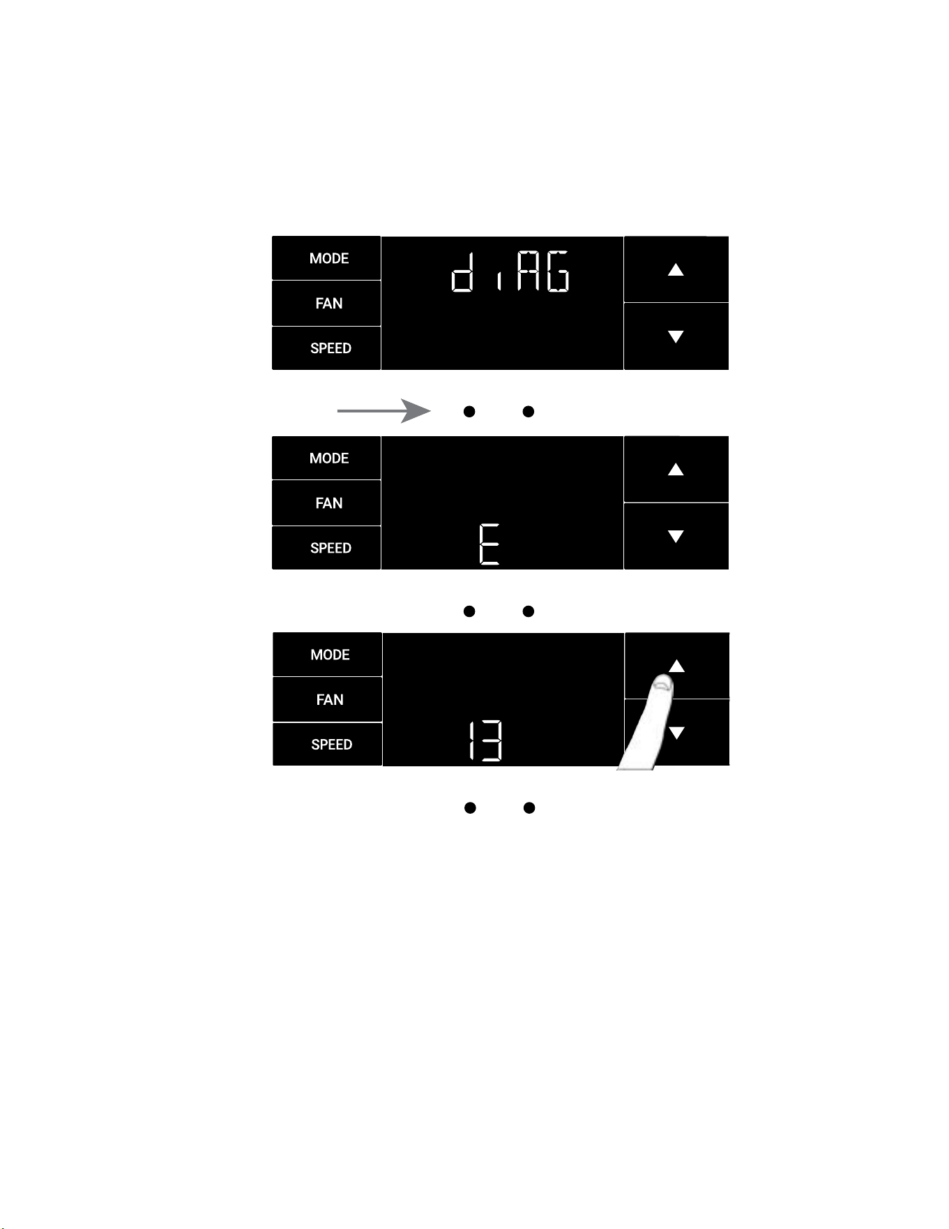
The diAG Menu
• This menu is used to access the diagnostic codes. See Figure 339.
• Selecting this sub-menu shows the E that represents “Error.” See Figure 340.
• Toggle through the error codes using the arrow keys. See Figure 341.
Figure 339
MENU RETURN
Figure 340
MENU RETURN
Figure 341
32 32
OPERATION
User Interface
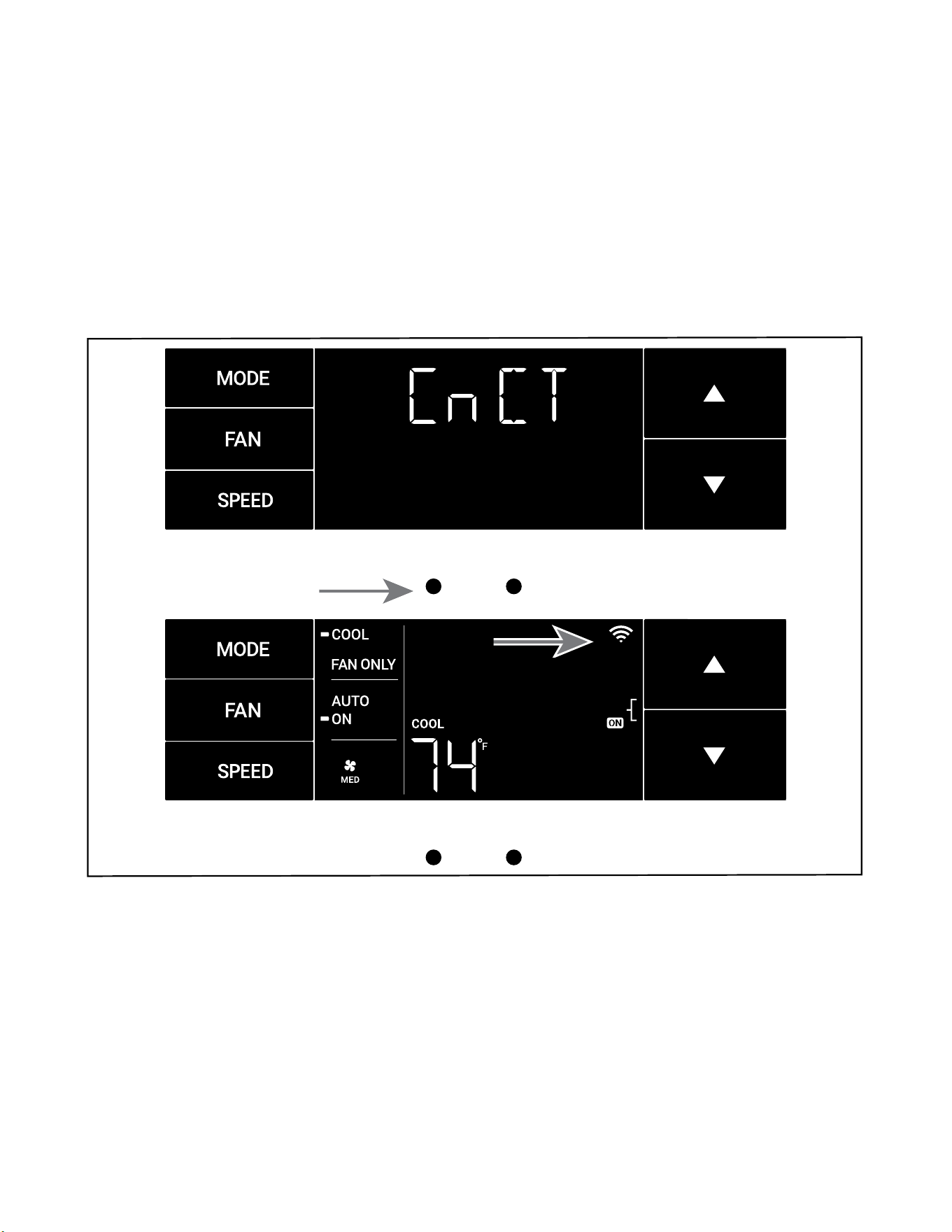
The CnCT Menu (WiFi Connection)
This menu is used to turn on Wi-Fi connection.
This is the CnCT menu. Pressing the menu button will activate Wi-Fi. See Figure 342.
To setup WiFi, refer to Wi-Fi setup instructions.
The Wi-Fi symbol in the top right corner of the display shows Wi-Fi connection is on. See Figure 343.
Figure 342
MENU RETURN
Figure 343
MENU RETURN
33 33
SYSTEM - The MODE button allows you to sequentially select up to four modes of operation:
AUTO Available on select models
COOL
HEAT Available on select models
FAN ONLY
AUTO FAN (No Cooling Demand)
When in AUTO mode, the fan only operates when the system has a demand to cool or heat the room.
In the ON fan mode, the fan operates all the time. The system periodically cools or heats the fan’s airow but the ow of air does not stop.
UP and DOWN Arrows - Pressing either an UP or DOWN button changes the system’s set-point (desired room temperature). These buttons are also
used to make system parameter changes later in this manual.
One press equals 1 degree of change in Fahrenheit mode. One press equals 0.5 degree change in Celsius mode.
TIMER
The timer can be engaged or disengaged from the control panel. This is done by pressing or holding the UP and DOWN arrows simultaneously for three
seconds.
OTHER FUNCTIONS
°F – °C Select
To switch from degrees Fahrenheit (F) to Celsius (C), press the MENU button and enter the F-C sub-menu.
FAN SPEED - Depending on your model, the FAN SPEED button allows you to toggle between three or four modes of operation: LOW, MEDIUM, HIGH and
MAX.
Alerts
W hen the lter n ee d s to b e cl ean e d or r ep l a ced , th e C H EC K F ILTE R i c o n d ispl a ys . Refer to Rou tine Mai n te n ance fo r l ter m aintena n ce r eq u ire m ent s .
The alert can be dismissed by pressing the FAN and SPEED buttons for 3 seconds.
Lock Control Panel
To lock/ unlock the front panel controls, navigate to the “LOCK” sub-menu found after clicking the MENU button. The lock requires a four digit pass code
to lock/ unlock the unit. This pass code will be required to enter the menu to unlock the unit. Be sure to write the password down and retain for future
use. The LOCK icon illuminates to indicate the locked status.
The LOCK icon disappears to indicate unlocked status.
External Control Status
The Wi-Fi icon illuminates to indicate that the system is receiving a Wi-Fi connection. The Wi-Fi icon also provides information about the signal
strength.
Advanced Functions
The functions mentioned in the following section may or may not be available depending on the air conditioner model.
Modify the TIMER Function
Navigate to the TIME menu to set the timer.
OPERATION
Control Panel
34 34
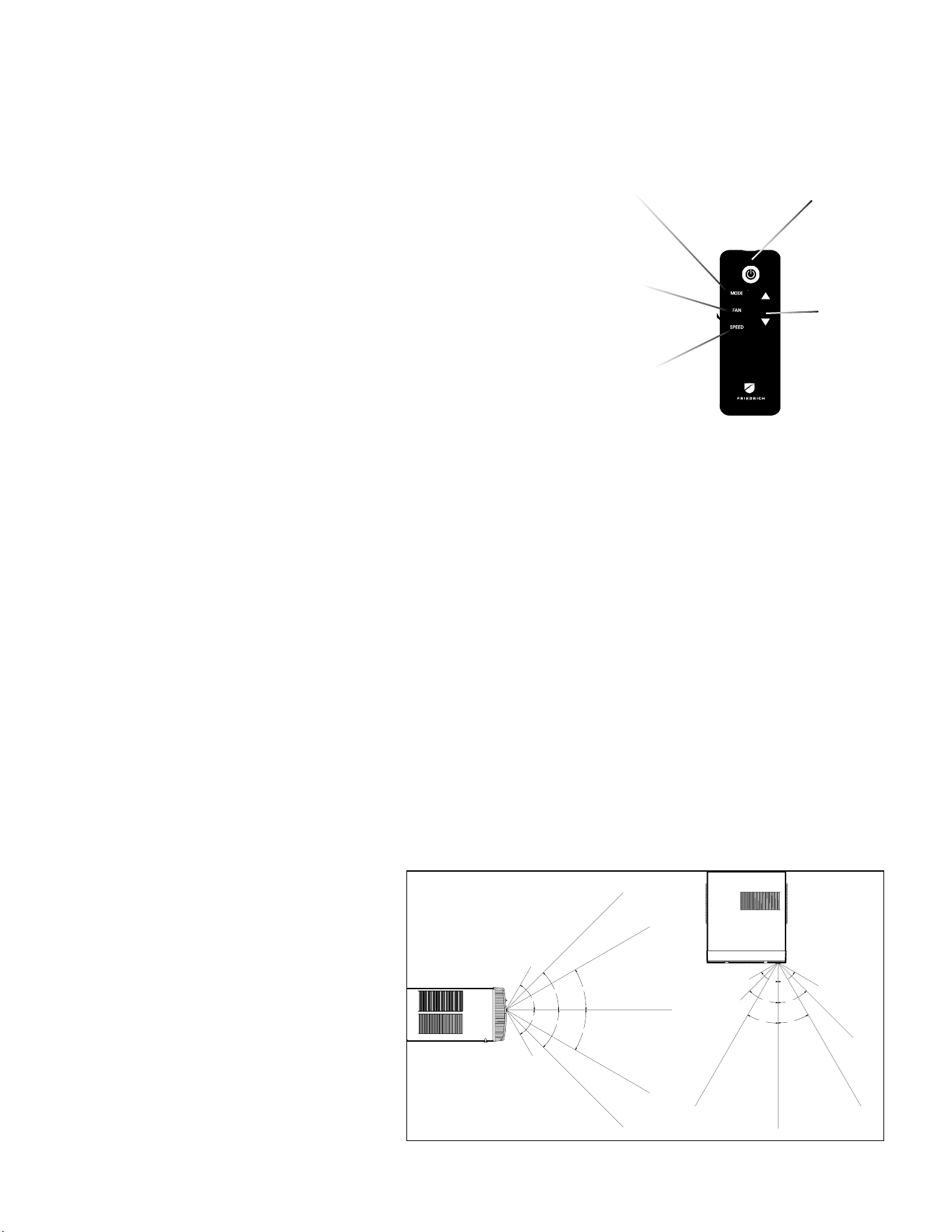
Remote Control - Refer to Figure 344 during operation description.
Getting Started - Install two (2) AAA batteries in the battery compartment located on the back
of the unit.
Operation - The remote control should be within 25 feet of the air conditioner for operation (refer
to Figure 345 for effectiveness). Press the power button to turn the remote on. The remote
will automatically power off after 15 seconds if the buttons are not being pressed. The remote
must be on to control the unit.
POWER Button - Turns remote and unit on and off.
MODE Button - Allows the user to sequentially select the following: AUTO, COOL, HEAT, and
FAN ONLY operations. When the button is pressed, the display indicates which mode has
been selected via a display message. Note that when the heating function is not available, the
system will automatically skip the HEAT mode.
FAN Button - Selects between automatic (AUTO FAN) or CONTINUOUS operation. In the AUTO
FAN mode, the fan only turns on and off when the compressor operates or the heat function
is enabled.
NOTE: AUTO FAN is not available in the FAN ONLY Mode, the display indicates CONTINUOUS.
In the CONTINUOUS mode, fan speed is determined by your selection on the FAN SPEED
button.
SPEED Button - Used to sequentially select new fan speed, plus AUTO operation. When the
FAN SPEED button is pressed, the fan speed icon (triangle) changes to indicate the new speed
level. Fan speed automatically varies depending on the set temperature on the control panel
and the actual room temperature. For example, if there is a big difference between your set
temperature and the actual room temperature, the system fan speed increases to HIGH. It
remains at this speed until the room temperature matches the set temperature.
UP and DOWN Arrows - Pressing either the UP or DOWN button changes the desired room
temperature. The factory preset lower and upper limits are 60 °F (16 °C) and 99 °F (37 °C).
These buttons are also used to navigate between function options when using the User
Menu or Maintenance Mode.
NOTE: Some units may have been provided with an alternate remote control, which contains
an LCD Basic functions are the same.
30°
45°
60°
30°
45°
60°
25ft
25ft
8ft
4ft
25ft
16ft
6ft
30°
30°
45°
60°
45°
60°
25ft
25ft
25ft
8ft
25ft
25ft
7.5ft
TOP VIEW
OPERATION
Remote Control
Figure 345 (Remote Control Effectiveness)
POWER
MODE
UP and
DOWN
ARROWS
FAN
SPEED
SIDE VIEW
FIgure 344 (Remote Control)
Remote Effectiveness
Handheld Remote - Has an operating range of up to 25 ft.
The infrared remote control signal must have a clear path
to transmit the command to the air conditioning unit. The
remote signal has some ability to “bounce” off of walls and
furniture similar to a television remote control. The diagram
below shows the typical operating range of the control in a
standard room with 8 ft high ceilings.
35 35
Cooling
Your air conditioner is designed to cool in warm weather when the outside temperature is above 60 °F (15.6 °C) and below 115 °F (46.1 °C), so it won’t cool a room
if it is already cool outside. If you want to cool a room in the spring or fall, select the FAN ONLY mode and set the Fresh Air/ Exhaust air control to Fresh Air. This
will bring in a supply of cooler outside air.
Condensation is normal
Air conditioners actually pump the heat and humidity from your room to the outside. Humidity becomes water, and your air conditioner will use most of the water
to keep the outside coil cool. If there is excessive humidity, there may be excess water that will drip outside. This is normal operation.
Frosting
This usually occurs because of insufficient airflow across the coils, a dirty filter, cool damp weather, or all these. Set the SYSTEM mode to FAN ONLY and the frost
will disappear. Setting the thermostat a little warmer will probably prevent the frosting from recurring.
Noises
Friedrich units are designed to operate as quietly as possible. An air conditioner mounted in a wall is quieter than one mounted in a window. It is important to
ensure that the chassis seal gasket is properly installed (refer to SPECIFICATIONS FIGURE 205).
OPERATION
Unit
Compressor and Reversing Valve Control
Active Mode Compressor Reversing Valve
Cooling On De-Energized
Heat - Pump On Energized
Heat - Electric Off
Fan Only Off
Reversing Valve
The reversing valve stays in the last state until a call for heat or cooling .
The reversing valve only changes when required to provide cooling or heat pump. Leave the reversing valve in it’s last state until it’s required
to change
.
Figure 346 (Compressor Operation)
36 36
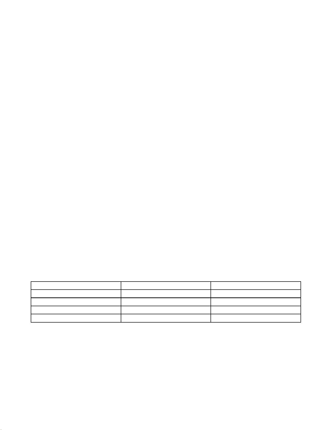
OPERATION
Unit Cooling Mode
Once the indoor ambient temperature rises past the cool demand threshold (Cool Set Point + 1.5 ˚F) (see gure below), and the
compressor is not locked out, the cooling cycle begins. As shown in the gure below, the fan is started 5 seconds prior to the
compressor. Once the indoor ambient temperature has been lowered to the cool set point (Cool Set Point minus .25 ˚F), the cooling
cycle starts to terminate by shutting off the compressor. After a 30 seconds delay, the fan is shut off. (See gure below for graphic
details)
Figure 347 (Cooling Control )
Unit Heating Mode Control Operation
There are two heating methods: Heat Pump and Electric Resistance Heat.
There are 2 types of units that provide heating:
Heat Pump with Electric Heat (
KHVS10B11A , KHVS12B33A, KHVM24B34A, KHVL28B35A ,
KHVQ10B11A
WHVT12B33A, WHVT14B33A
)
Cool with Electric Heat
37 37
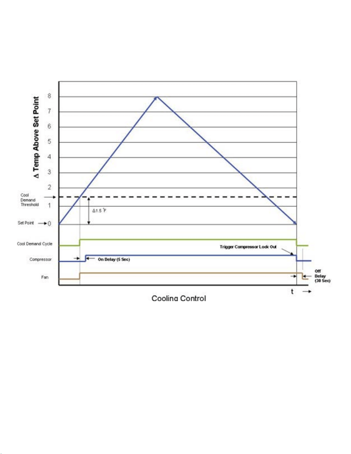
OPERATION
Unit Heat Control Operation - HeatPump With Electric Heat
If the ambient indoor temperature is below the heat demand threshold (1.5˚F below the heat set point temperature), and the
compressor is not locked out, turn on compressor. If the ambient indoor temperature is .25˚F above the heat set point turn off the
compressor..
Figure 348 (Heat Control (Heat Pump & Electric Heat)
If the compressor is locked out & electric heat is available:
1. Turn on the electric heat until the compressor is not locked out.
2. After lockout, turn off the electric heat, wait 5 seconds, then turn on the compressor.
If Electric Heat is Available:After the Heat button is initially pressed, the unit will run the electric heater rst until the initial set point is satised
(Hot Start Feature). After the initial start, the unit will switch to Heat Pump heat and decide between Heat Pump heat and Electric heat based on the
following two monitored conditions:
Condition 1
If the outdoor coil temperature sensor drops to 30 ˚F or less for 2 consecutive minutes, the unit will switch to electric heat if available. Thereafter, the
unit will switch back to Heat Pump heat if the outdoor coil temperature sensor rises to 45 ˚F or greater.
If Electric Heat is not available (out of order) and the outdoor coil temperature sensor drops to 30 ˚F or less for 2 consecutive minutes, then the
compressor and fan will turn off. Thereafter, the unit will switch back to Heat Pump heat if the outdoor coil temperature rises to 45 ˚F or greater.
Condition 2
If the delta (set point temperature minus the ambient indoor temperature) is greater than 5 ˚F, then the unit will switch to electric heat, if available.
The unit will continue to operate with electric heat until the heat demand is satised. Note that the electric heat switches on after the delta temp
passes 5°F and the heat pump switches off. Also note that the electric heat will run until the heat demand is satised. When another heat demand
cycle is initiated, the heat pump will run unless the delta temp is greater than the electric heat threshold.

38 38
OPERATION
Unit Heat Control Operation - Heat Pump With Electric Heat (Continued)
Automatic Emergency Heat
If the sealed system fails with a bad reversing valve or anything that causes the indoor coil to get colder than the indoor ambient
temperature:
1) If the indoor coil thermistor senses a 5 degree temperature drop as compared to the ambient temperature thermistor and this
lasts up to 5 minutes, the control board will switch the unit to electric heat and continue heating with it.
Note: It is Ok to continue to use the unit with the electric heater until the heat pump is repaired.
Heat Control Operation - Electric Heat Only
When in the Heat mode, with and without Fan Mode Auto (Fan cycling):
If the indoor ambient temperature is below the Heat Demand Threshold (Heat Set Point minus 1.5 ˚F), turn on electric heat. If Ambient
is 0.3 ˚F above the Heat Set Point turn off the electric heat.
System Mode Auto
This mode provides automatic change over between cool and heat. The auto mode runs based on the indoor ambient temperature vs.
the Demand Thresholds. It is only available in Heat-Cool Unit.
Notes:
There is a buffer zone between the cool and heat set points where no heating or cooling is allowed to occur. It is critical that the Cool
Demand Threshold be greater than the Heat Demand Threshold by a minimum of 3° while in the Auto System Mode. For example,
if a user enters a value for the Auto Cooling Set Point that violates the minimum delta 3° rule, the Auto Heating Set Point will adjust
accordingly.
Automatic Change Over Delay (Cool with Heat Units)
The change over delay ensures that any system heating or cooling over shoot does not trigger an opposite demand cycle. The change
over delay = 15 min. This timer blocks the opposite demand cycle from running until the timer expires. As an example, if the last
demand was a cool cycle, and another cool cycle is requested, the timer will not block the request. However, if the last demand cycle
was a cool cycle, and heat cycle is requested, the timer will block the request until the change over delay is expired.
Compressor Lock Out Time
The lockout feature ensures that the compressor is de-energized for a period of time. The timer varies randomly from 180 to 240
seconds
The compressor lockout is initiated every time the compressor is “off” due to:
(1) Satisfying the temperature set point
(2) Changing mode to fan only or heat
(3) Turning the unit off
(4) Control is rst plugged in or power is restored after failure
(5) Line power is restored from a brown out condition
Cooling Fan Delay
Fan cycle/Auto mode only
When unit cycles cooling ON – starts the fan 5 seconds EARLY. When unit cycles cooling OFF – DELAYS the fan off for 30 seconds.

39 39
OPERATION
Heating Fan Delay
This is only for fan Mode Auto (Fan cycles with cool/heat operation) and not for continuous fan mode. When unit cycles Heating ON – starts the fan 5
seconds EARLY. When unit cycles Heating OFF – DELAYS the fan off for 15 seconds.
Fan Speed Change Delay
Relay activation is delayed by a minimum number of seconds. The default for this value is 2 seconds and is used to eliminate relay chatter.
System Mode Fan Only
The fan is turned on and runs at the specied manually set speed.
Only the Fan is turned on. Cool or Heat operation are off.
(This is different than FAN MODE ON where the fan is on with the cool or heat operation).
Fan Only Rules
1. If the SYSTEM FAN ONLY MODE is selected, the Auto fan mode is disabled, and the fan mode is forced to continuous. In addition, the auto fan speed
is disabled. If the user presses the fan speed key, the menu will skip over the auto selection. The set point temperature display is off.
2. Any fan speed may be manually selected during Fan Only Mode.
Fan Operation (Front Panel Mode)
Heat – Cool – Auto – Fan Only
Cooling only models (Model numbers with the prex KCS or KCM ) have 4 speeds. All other Models have 3 speeds.
Fan ICON Detail
The system may have a 3 or 4 speed fan. The Fan Speed ICON will Display as LOW, MED, HI, or MAX depending on which speed is selected .

40 40
OPERATION
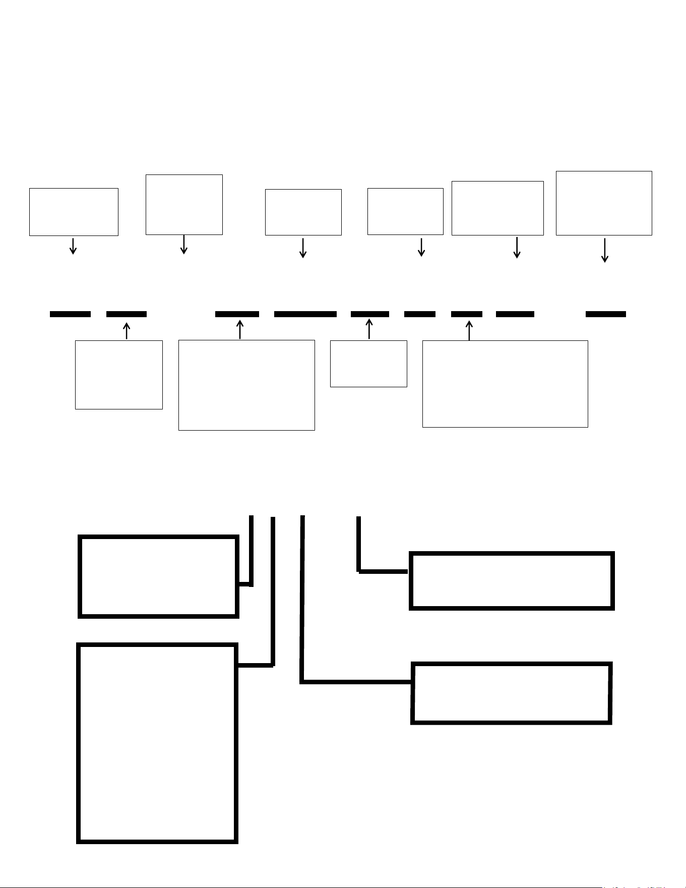
General Knowledge Sequence Of Refrigeration
A good understanding of the basic operation of the refrigeration system is essential for the service technician. Without this understanding, accurate
troubleshooting of refrigeration system problems will be more difficult and time consuming, if not (in some cases) entirely impossible. The refrigeration
system uses four basic principles (laws) in its operation they are as follows:
1. “Heat always flows from a warmer body to a cooler body.”
2. “Heat must be added to or removed from a substance before a change in state can occur”
3. “Flow is always from a higher pressure area to a lower pressure area.”
4. “The temperature at which a liquid or gas changes state is dependent upon the pressure.”
The refrigeration cycle begins at the compressor. Starting the compressor creates a low pressure in the suction line which draws refrigerant gas (vapor) into
the compressor. The compressor then “compresses” this refrigerant vapor, raising its pressure and its (heat intensity) temperature.
The refrigerant leaves the compressor through the discharge Line as a hot High pressure gas (vapor). The refrigerant enters the condenser coil where it gives
up some of its heat. The condenser fan moving air across the coil’s finned surface facilitates the transfer of heat from the refrigerant to the relatively cooler
outdoor air.
When a sufficient quantity of heat has been removed from the refrigerant gas (vapor), the refrigerant will “condense” (i.e. change to a liquid). Once the
refrigerant has been condensed (changed) to a liquid it is cooled even further by the air that continues to flow across the condenser coil.
The design determines at exactly what point (in the condenser) the change of state (i.e. gas to a liquid) takes place. In all cases, however, the refrigerant must
be totally condensed (changed) to a Liquid before leaving the condenser coil.
The refrigerant leaves the condenser Coil through the liquid line as a warm high pressure liquid. It next will pass through the refrigerant drier (if equipped). It
is the function of the drier to trap any moisture present in the system, contaminants, and large particulate matter.
The liquid refrigerant next enters the metering device. The metering device is a fixed orifice. The purpose of the metering device is to “meter” (i.e. control or
measure) the quantity of refrigerant entering the evaporator coil.
In the case of the fixed orifice this is accomplished (by design) through size of the orifice, and the pressure difference present across the device.
Since the evaporator coil is under a lower pressure (due to the suction created by the compressor) than the liquid line, the liquid refrigerant leaves the
metering device entering the evaporator coil. As it enters the evaporator coil, the larger area and lower pressure allows the refrigerant to expand and lower
its temperature (heat intensity). This expansion is often referred to as “boiling” or atomizing. Since the unit’s blower is moving indoor air across the finned
surface of the evaporator coil, the expanding refrigerant absorbs some of that heat. This results in a lowering of the indoor air temperature, or cooling.
The expansion and absorbing of heat cause the liquid refrigerant to evaporate (i.e. change to a gas). Once the refrigerant has been evaporated (changed to a
gas), it is heated even further by the air that continues to flow across the evaporator coil.
The particular system design determines at exactly what point (in the evaporator) the change of state (i.e. liquid to a gas) takes place. In all cases, however,
the refrigerant must be totally evaporated (changed) to a gas before leaving the evaporator coil.
The low pressure (suction) created by the compressor causes the refrigerant to leave the evaporator through the suction line as a cool low pressure vapor.
The refrigerant then returns to the compressor, where the cycle is repeated.
Figure 349 (Refrigeration Sequence Of Operation)
41 41
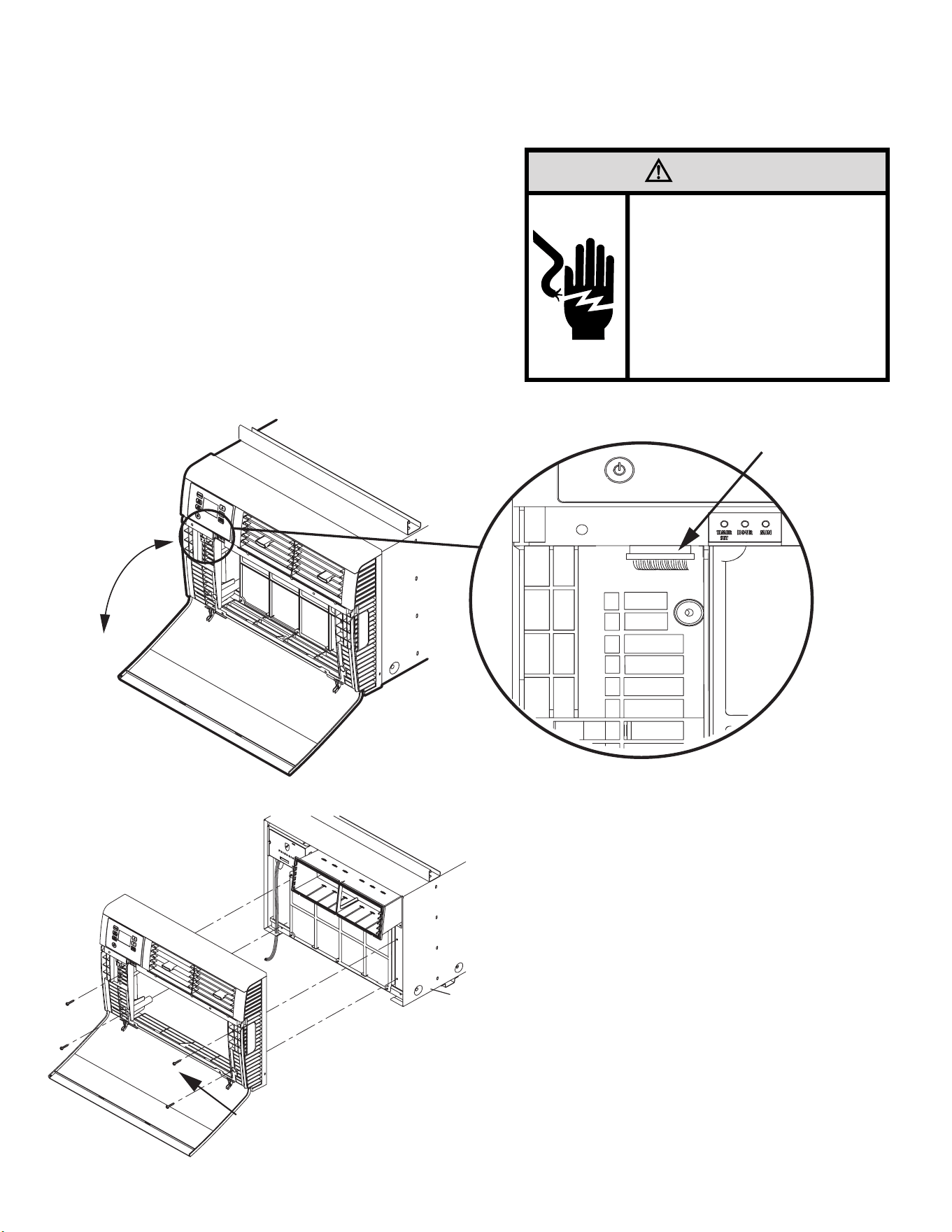
WARNING
ELECTRIC SHOCK HAZARD
Disconnect power to the unit before
servicing. Failure to follow this warning
could result in serious injury or death.
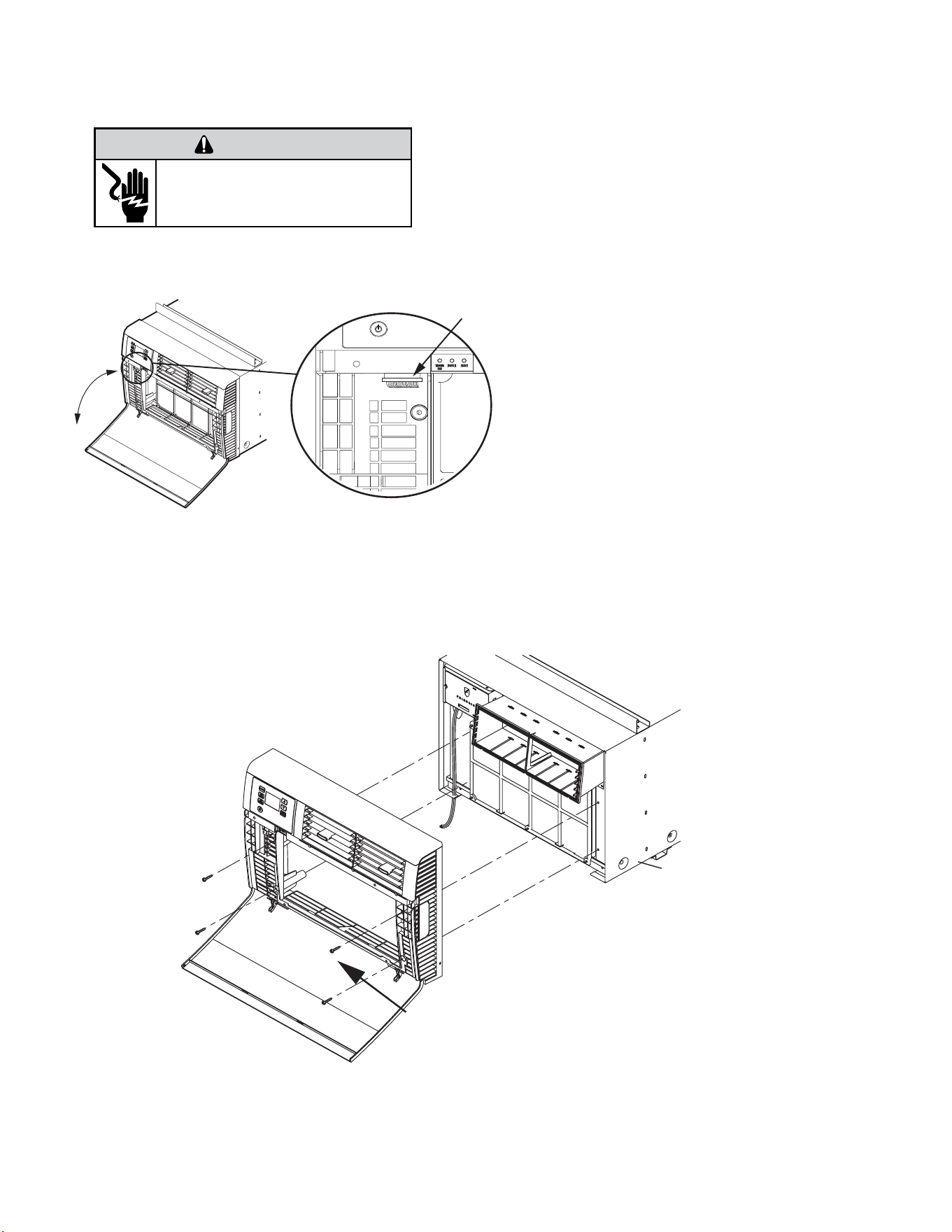
Remove the decorative front cover.
1. Using a 1/4” nut driver loosen the four (4) captive screws as shown in figure 401
Install the decorative front cover.
OPTIONAL: The factory assembles the supply cord so that it exits the left side of the unit at the bottom. At the consumer’s discretion, pull the supply cord taut through the loops (refer
to Cord Routing Change, Section C.6) and route the cord down.
STEP 14. To attach and prevent damage to the front grille, align the cord notch over the cord and center the fresh air lever, then align and tighten the four (4) captive screws as
indicated by the arrows in Figure 401 before closing the front panel, be sure the lter is in place. Make sure curtains do not block the side air intakes.
Figure 401 (Remove and Install the Front Cover)
ROUTINE MAINTENANCE
Remove and Install Front Cover -Kuhl
42 42
WARNING
ELECTRIC SHOCK HAZARD
Disconnect power to the unit before
servicing. Failure to follow this warning
could result in serious injury or death.
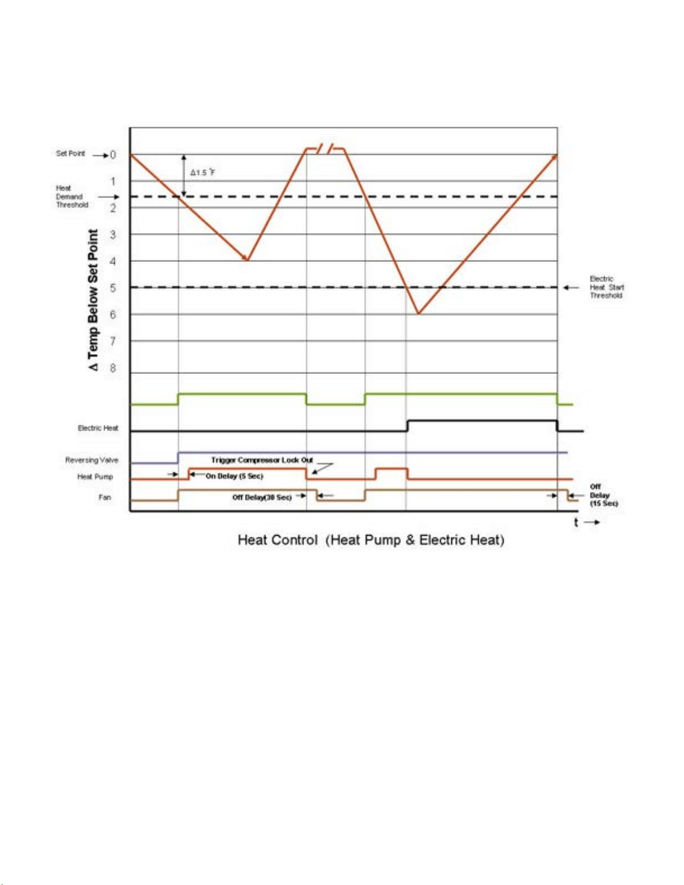
Remove the decorative front cover.
1. Remove EntryGard™ screws if installed.
2. Open the decorative front cover door.
3. Locate and disconnect electronic control power
cable harness.
4. Using a 1/4” nut driver, remove 4 screws attaching
decorative front cover.
Save to reinstall later.
5. Remove decorative front cover. Store in a safe place
to reinstall later.
Install the decorative front cover.
1. Reinstall the 4 screws attaching decorative front
cover.
2. Locate and reconnect electronic control power
cable harness
3. Close the decorative front cover door.
4. Reinstall the EntryGard™ screws if installed.
Figure 402 (Remove and Install the Front Cover)
ROUTINE MAINTENANCE
Remove and Install Front Cover -Kuhl Q
43 43
WARNING
ELECTRIC SHOCK HAZARD
Disconnect power to the unit before
servicing. Failure to follow this warning
could result in serious injury or death.
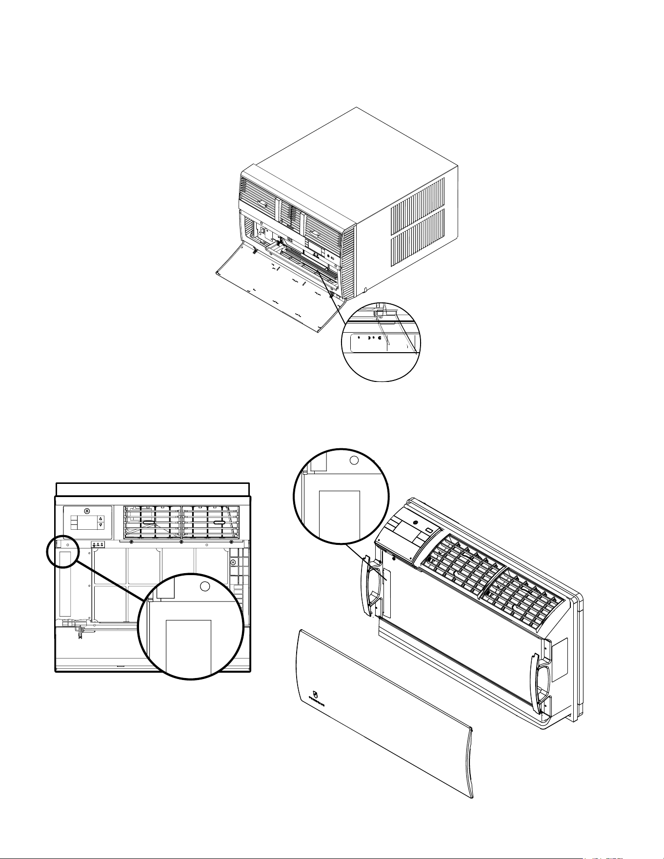
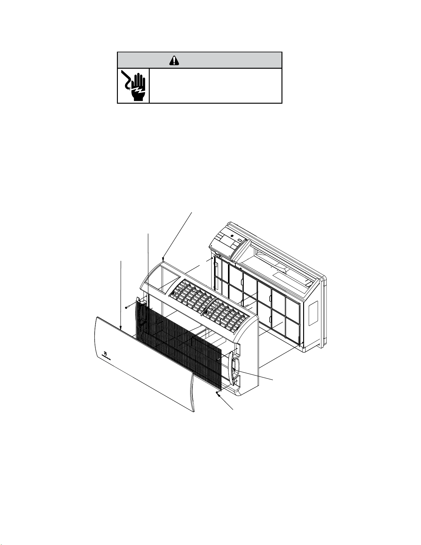
Remove the decorative front cover.
1. Remove the FRONT PANEL. Using the handles, pull panel out until it is released from the two retaining snaps. Place the cover aside
carefully.
2. Remove the lter by pulling it from the handles releasing it from the slots on the frame. Wash the lter with water to remove all dust
and then rinse, remove water excess and let it dry. Do not twist. Remove the intake grill by applying slight outward pressure on the
chassis removal handles and popping grill out out of slots.
3. Remove the 4 screws and remove the decorative front assembly.
Install the decorative front cover.
1. Install the front decorative assembly with 4 screws .
2. Install the lter by inserting each tab in their respective slot.
3. Install Intake grill by applying slight outward pressure on the chassis removal handle.
Figure 403 (Remove and Install the Decorative Front Assembly)
Screws (4 ea)
Decorative Front Assembly
Filter
Intake Grill
Chassis removal
Handel
ROUTINE MAINTENANCE
Remove and Install Front Cover -Wallmaster
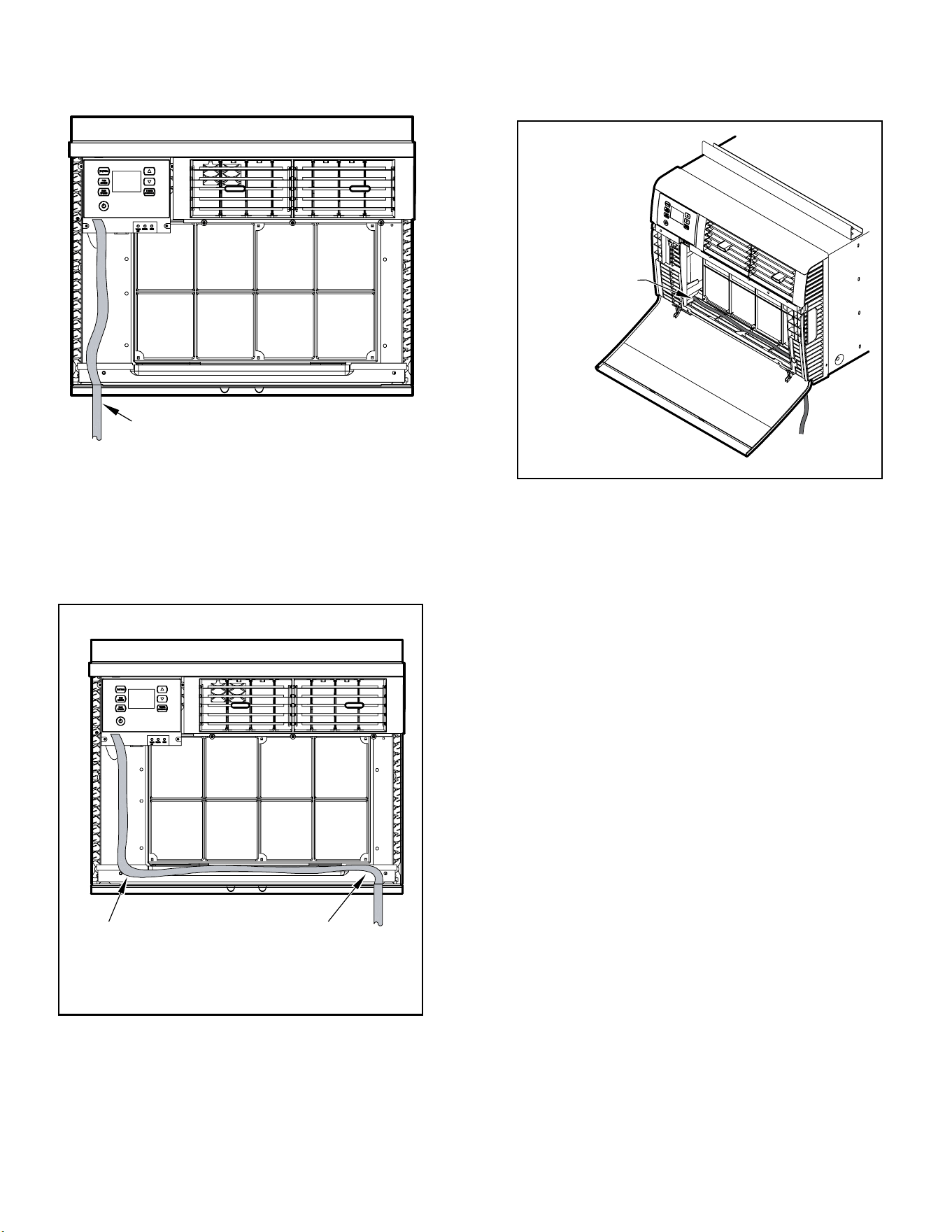
44 44
ROUTINE MAINTENANCE
Cord Routing Change-Kuhl
Unplug unit.
WARNING
Electrical Shock Hazard
Make sure your electrical receptacle has the
same configuration as your air conditioner’s
plug. If different, consult a Licensed Electrician.
Do not use plug adapters.
Do not use an extension cord.
Do not remove ground prong.
Always plug into a grounded 3 prong outlet.
Failure to follow these instructions can result in
death, fire, or electrical shock.
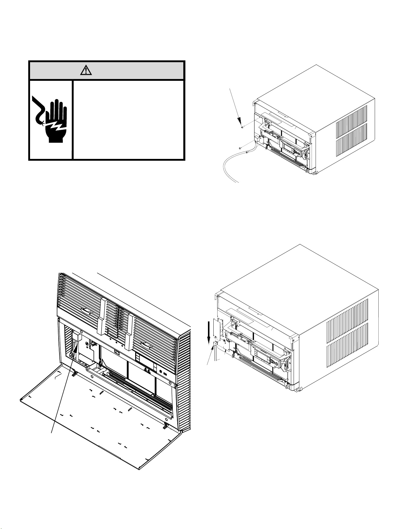
For convenience and optimum appearance, the direction that the power cord
exits the unit may be changed from left to right by following the procedure below.
Select the exit location on the left or right based on proximity to the power outlet.
The 30 Amp power Cord installation is shown in Figure 404 If your unit plug is in
this conguration, you do not need to rotate plug in order to change the routing.
You can skip to step 5.
STEP 1 Remove the 3 screws as shown from the access panel.
Save to reinstall later.
Figure 405
Figure 404
STEP 2. Pull electrical cord strain relief downward until free and rotate 90
degrees to the right.
Figure 406
ELECTRICAL CORD
STRAIN RELIEF
PANEL SCREWS (3)
90°
PLUG MOUNTED
MIDWAY ON PANEL
45 45
ROUTINE MAINTENANCE
Cord Routing Change-Kuhl
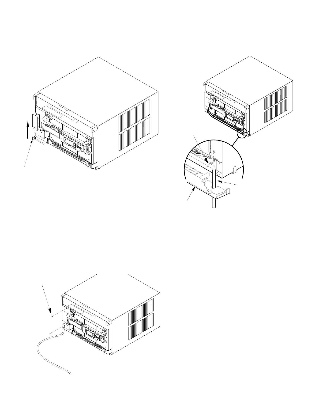
STEP 3. Push electrical cord strain relief back upward into the electrical control
panel.
Figure 407
STEP 4. Reinstall the 3 screws removed earlier to secure electrical control
panel.
ENSURE THE ELECTRICAL CORD STRAIN RELIEF IS FLUSH
WITH THE TOP OF ELECTRICAL CONTROL PANEL.
Figure 408
STEP 5. If running power cord to the right of the unit, install the cord into
the cord retainer clips along the bottom front of the unit.
CORD RETAINER
CLIPS
POWER
CORD
FRONT
GRILLE
Figure 409
PANEL SCREWS (3)
46 46
ROUTINE MAINTENANCE
Cord Routing Change-Kuhl Q
Unplug unit.
Your Kühl Q unit will come with the power cord already installed and routed
to the left side of the unit.
For convenience and optimum appearance the direction of the power cord
can be changed from left to right by following the procedure below. Select
the exit location on the left or right based on proximity to the power outlet.
STEP 1.
Remove the decorative front cover.
A. Open the decorative front cover.
B. Locate and disconnect electronic control power cable harness.
C. Remove 4 screws attaching decorative front cover.
Save to reinstall later.
D. Remove decorative front cover. Store in a safe place to reinstall later.
WARNING
Electrical Shock Hazard
Make sure your electrical receptacle has the
same configuration as your air conditioner’s
plug. If different, consult a Licensed Electrician.
Do not use plug adapters.
Do not use an extension cord.
Do not remove ground prong.
Always plug into a grounded 3 prong outlet.
Failure to follow these instructions can result in
death, fire, or electrical shock.
Disconnect Plug
STEP 2. Route the cord along bottom inside of the unit (see Figures 412 and 413),
under the lower left mounting screw embossments and exit the cord
through right side cord opening (see Figure 413) of the decorative front
cover. Decorative front cover will keep cord in place.
STEP 3.
Reinstall the 4 screws removed earlier to secure decorative front cover
with cord exiting to the front bottom of the unit (4 screws retained from
Step 1).
Remove Screws
Step 1.A
Step 1.B
Step 1.C
Figure 410
Figure 411
47 47
ROUTINE MAINTENANCE
Cord Routing Change-Kuhl Q
CLOSE UP OF
CORD UNDER
LEFT MOUNTING
SCREW
EMBOSSMENT
FACTORY SETTING WITH
LEFT-SIDE CORD PLACEMENT
STEP 2: NEW CORD ALIGNMENT FOR ROUTING
CORD
EXIT TO THE RIGHT OF UNIT
Figure 412
Figure 413
Figure 414

48 48
Coils & Chassis
NOTE: Do not use a caustic (alkaline) or acidic cleaning agent on coils or base pan. Use a biodegradable cleaning agent and de greaser.
The use of harsh cleaning materials may lead to deterioration of the aluminum ns or the coil end plates.
The indoor coil and outdoor coils and base pan should be inspected periodically (annually or semi-annually) and cleaned of all debris
(lint, dirt, leaves, paper, etc.) as necessary. Under extreme conditions, more frequent cleaning may be required. Clean the coils with and
base pan with a coil comb or soft brush and compressed air or vacuum. A low pressure washer device may also be used; however, you
must be careful not to bend the aluminum n pack. Use a sweeping up and down motion in the direction of the vertical aluminum n
pack when pressure cleaning coils.
NOTE
: It is extremely important to insure that none of the electrical and/ or electronic parts of the unit get wet when cleaning. Be
sure to cover all electrical components to protect them from water or spray.
Decorative Front
Use a damp (not wet) cloth when cleaning the control area to prevent water from entering the unit, and possibly damaging the electronic
control.
The decorative front and the cabinet can be cleaned with warm water and a mild liquid detergent. Do NOT use solvents or hydrocarbon
based cleaners such as acetone, naphtha, gasoline, benzene, etc.
The indoor coil can be vacuumed with a dusting attachment if it appears to be dirty. DO NOT BEND FINS. The outdoor coil can be gently
sprayed with a garden hose.
The air lter should be inspected periodically and cleaned if needed by vacuuming with a dust attachment or by cleaning in the sink using
warm water and a mild dish washing detergent. Dry the lter thoroughly before reinstalling. Use caution, the coil surface can be sharp.
Fan Motor & Compressor
The fan motor & compressor are permanently lubricated and require no additional lubrication.
Wall Sleeve
Inspect the inside of the wall sleeve and drain system periodically (annually or semi-annually) and clean as required. Under extreme
conditions, more frequent cleaning may be necessary. Clean both of these areas with an antibacterial and antifungal cleaner. Rinse both
items thoroughly with water and ensure that the drain outlets are operating correctly. Check the sealant around the sleeve and reseal
areas as needed.
Blower Wheel / Housing / Condenser Fan / Shroud
Inspect the indoor blower and its housing, evaporator blade, condenser fan blade and condenser shroud periodically (yearly or bi-yearly)
and clean of all debris (lint, dirt, mold, fungus, etc.). Clean the blower housing area and blower wheel with an antibacterial / antifungal
cleaner. Use a biodegradable cleaning agent and de greaser on condenser fan and condenser shroud. Use warm or cold water when
rinsing these items. Allow all items to dry thoroughly before reinstalling them.
Electrical / Electronic
Periodically (at least yearly or bi-yearly) inspect all control components: electronic, electrical and mechanical, as well as the power
supply. Use proper testing instruments (voltmeter, ohmmeter, ammeter, wattmeter, etc.) to perform electrical tests. Use an air
conditioning or refrigeration thermometer to check room, outdoor and coil operating temperatures.
Air Filter
To ensure proper unit operation, the air lter should be cleaned at least monthly, and more frequently if conditions warrant. The unit must
be turned off before the lter is cleaned.
ROUTINE MAINTENANCE
49 49
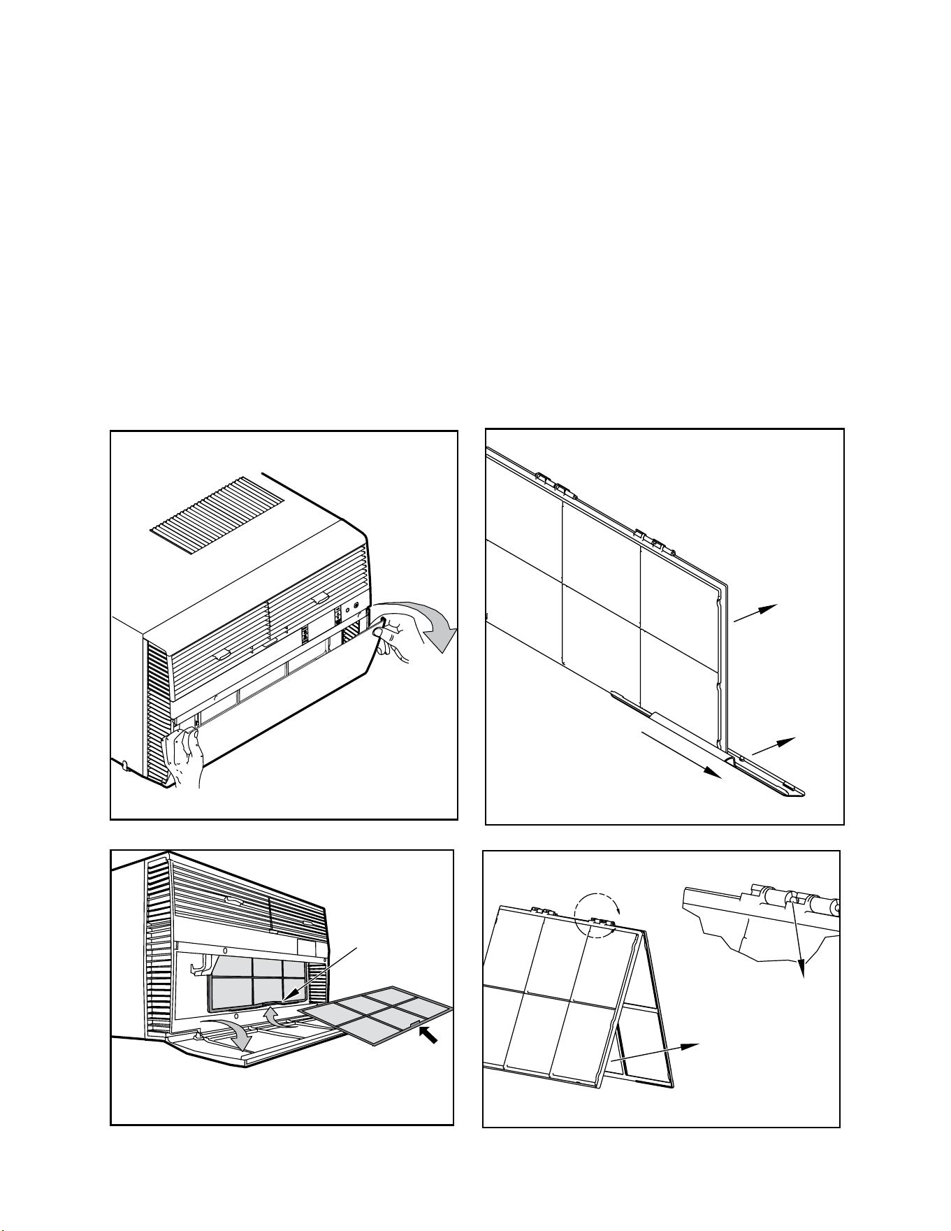
A
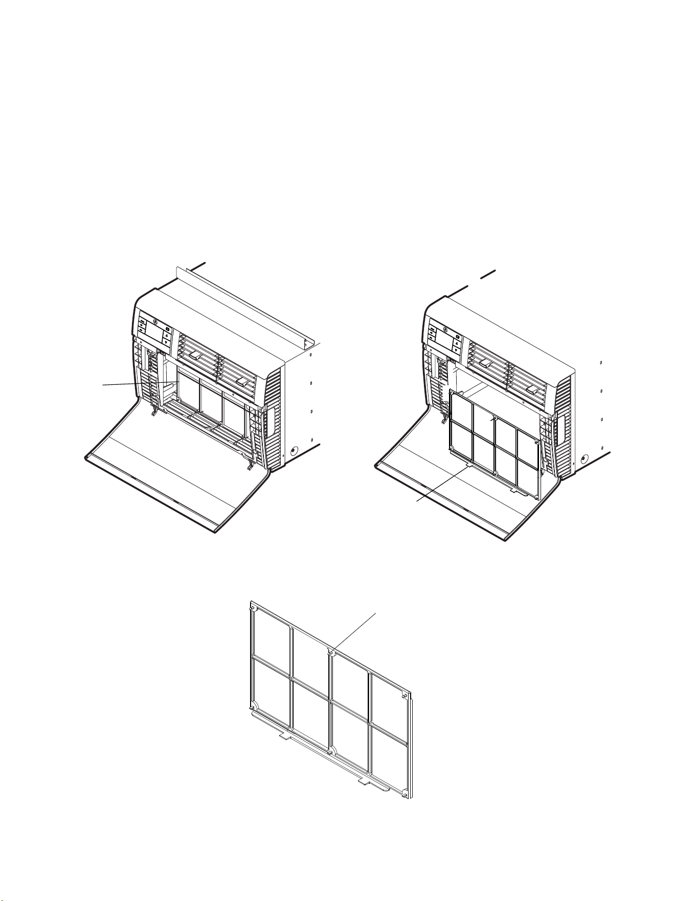
ROUTINE MAINTENANCE
Standard Filter Removal / Installation Instructions - Kuhl
1. Swing the door open, See Figure 404, and remove the lter by grasping the lter grip and pushing the lter holder upward and outward. See Figure
416.
2. Slide the lter grip out from the lter as shown in Figure 417.
NOTE: Make sure the front frame with the mesh lter is facing you.
3. Swing the front frame open. See Figure 418. Clean the front frame by washing the dirt from the lter. Use a mild soap solution if necessary. Allow
lter to dry.
4. Install the lter grip back into the lter by sliding it into the lter.
NOTE: The lter handle slides into the frame in only one direction. If the tab in the frame stops the handle from sliding in, slide the handle from the other
direction. DO NOT FORCE THE HANDLE INTO THE FRAME.
5. Install the lter back into the unit. Follow the instructions on the inside of the front door.
Figure 415
Figure 416
Figure 417
Figure 418
HANDLE
FILTER GRIP
FRONT
FRAME WITH
STANDARD
MESH FILTER
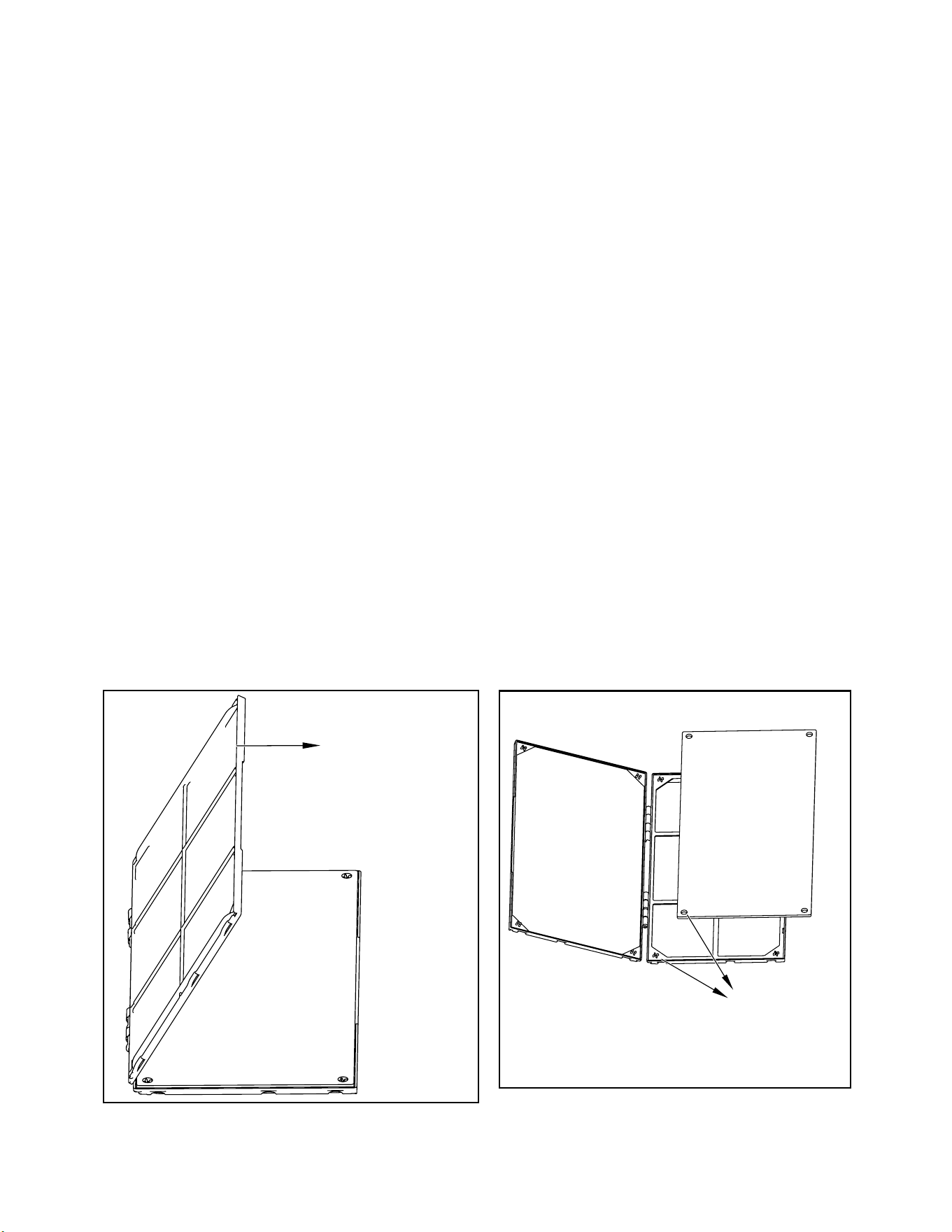
50 50
FRONT FRAME WITH
MESH FILTER
ALIGN HOLES WITH
PROTRUSION
ROUTINE MAINTENANCE
Premium Carbon Filter Removal / Installation Instructions -Kuhl
Figure 419
1. Remove the lter per Standard Filter Removal Installation Refer to Figure 415 and 416.
2. Hold the lter at the top and slide the grip out as shown on Figure 417.
3. If you already have a carbon lter installed remove the dirty lter by laying the lter down and swinging open the front frame as shown in Figure 419.
NOTE: Make sure the frame with the mesh is facing toward you.
4. Place the new carbon lter on the top of the back lter frame. The carbon lter has been cut to the correct dimension and should t within the frame
as shown in Figure 420.
NOTE:
The carbon lter is not a reusable lter, and needs to be replaced every three months for optimum efciency.
5. Slide the lter handle back on to hold the frames together and slide the assembly into the unit as per the instructions
on the door.
NOTE: The lter handle slides into the frame in only one direction. If the tab in the frame stops the handle from sliding in, slide the handle from the other
direction. DO NOT FORCE THE HANDLE INTO THE FRAME.
Figure 420
51 51
ROUTINE MAINTENANCE
Filter Removal / Installation Instructions - Kuhl Q
1. Swing the door open, See Figure 410,and remove the lter by grasping the lter grips and pulling the bottom towards you. . See Figure 411.
2. Clean the front frame by removing the carbon lter (if installed) and washing the dirt from the lter. Use a mild soap solution if necessary. Allow lter to dry.
NOTE: The carbon lter is not a reusable lter, and needs to be replaced every three months for optimum efciency.
3. Install new carbon lter (optional) by aligning holes on carbon lter with tabs on mesh lter. (See Figure 422).
4. Install lter and close door. See Figures 421 and 422.
Figure 421
Figure 421
Filter
Filter grip
Filter Frame Tabs
Figure 422
52 52
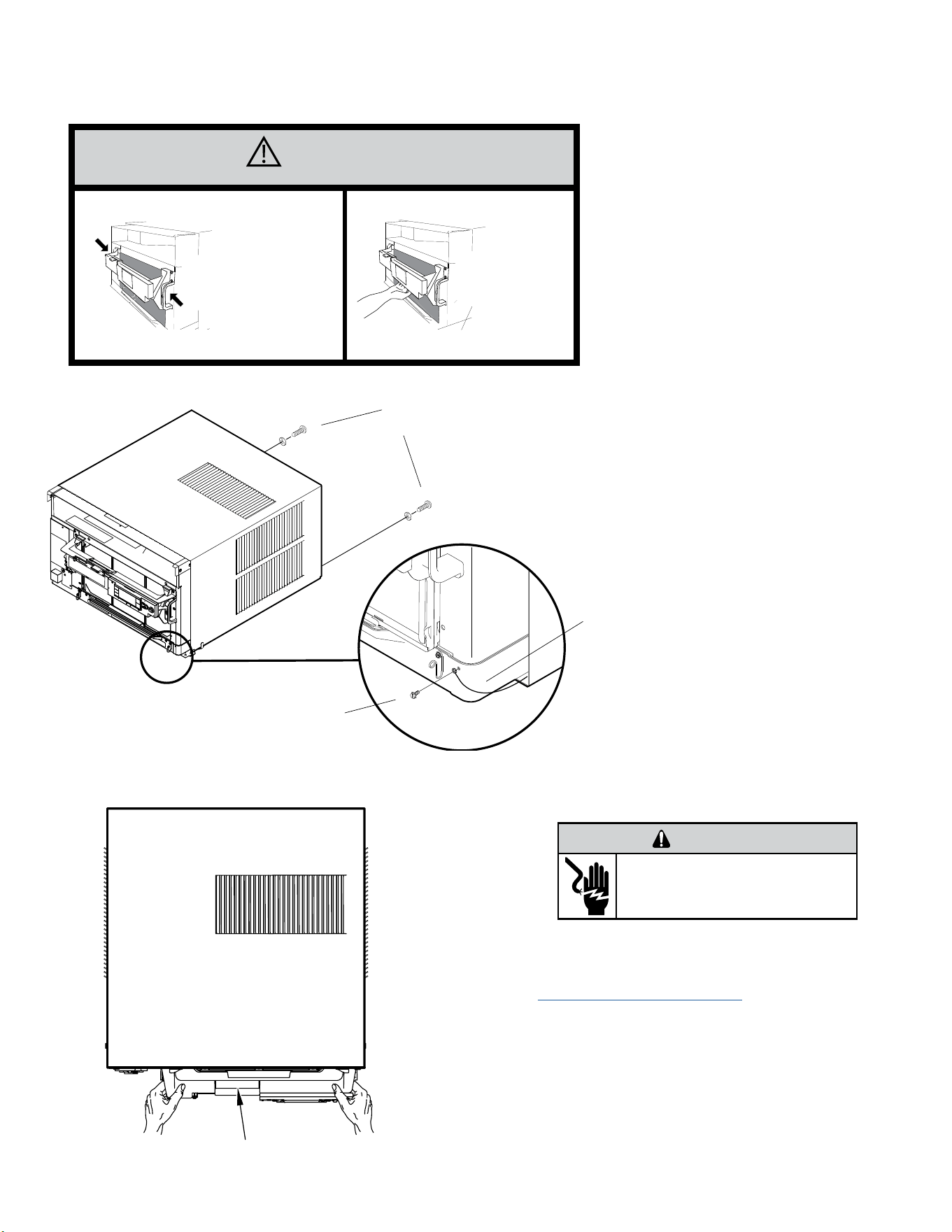
REMOVE AND INSTALL THE CHASSIS
Remove The Chassis - Kuhl
CAUTION
Use Handle
Locations
(both sides)
Do not push, pull,
or lift from
center of support
1. Remove the decorative front cover. See Routine
Maintenance Figure 401.
2. Remove the chassis Entrygard Retainer Wire by removing
the screw at the front right bottom corner. Save this screw
for reattachment after reinstalling the chassis. See Figure
423.
3. Hold the cabinet stationary then use the hand grips on both
ends of the control unit support bracket to pull the chassis out
of the cabinet . See gure 424.
WARNING
ELECTRIC SHOCK HAZARD
Disconnect power to the unit before
servicing. Failure to follow this warning
could result in serious injury or death.
Support Bracket
Figure 423 (Chassis Removal and Installation)
Figure 424 (Support Bracket)
RETAINER SCREWS
AND WASHERS
FAR RIGHT
SCREW
ENTRYGARD
RETAINER
WIRE
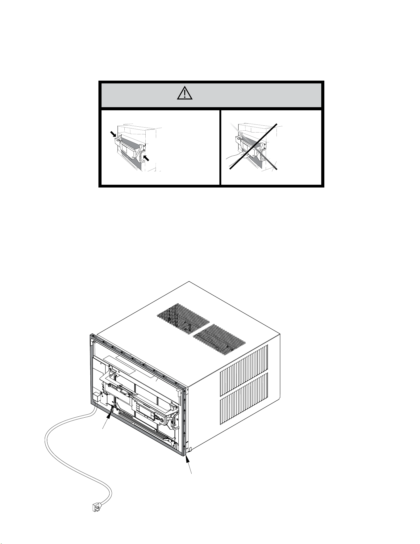
53 53
REMOVE AND INSTALL THE CHASSIS
Install The Chassis -Kuhl
CAUTION
Use Handle
Locations
(both sides)
Do not push, pull,
or lift from
center of support
1. Carefully team lift the chassis and set it into the cabinet.
2. Slide the chassis stopping approximately 3” from full insertion.
3. Insert the chassis seal gasket (See Figure 425) one inch deep between the chassis and the cabinet A paint stir stick or ruler might be helpful here.
Begin inserting the gasket at either bottom corner and go up the side, across the top, and down the opposite side. Then push the chassis all the way
into the cabinet.
NOTE: If the chassis seal gasket is not installed or installed improperly,the operation of the unit will be negatively affected. Operational noise and
outside noise will also amplied.
4. Slide the chassis in the remaining three (3) inches.
5. Reattach the EntryGard™ chassis and EntryGard™ retainer wire..
Figure 425 (Chassis Installation)
POWER CORD CLIP
NOTE: WHEN INSTALLING THE CHASSIS
GASKET, BEGIN AT EITHER BOTTOM
CORNER AND GO UP THE SIDE & ACROSS
THE TOP & DOWN THE OPPOSITE SIDE
CHASSIS SEAL GASKET
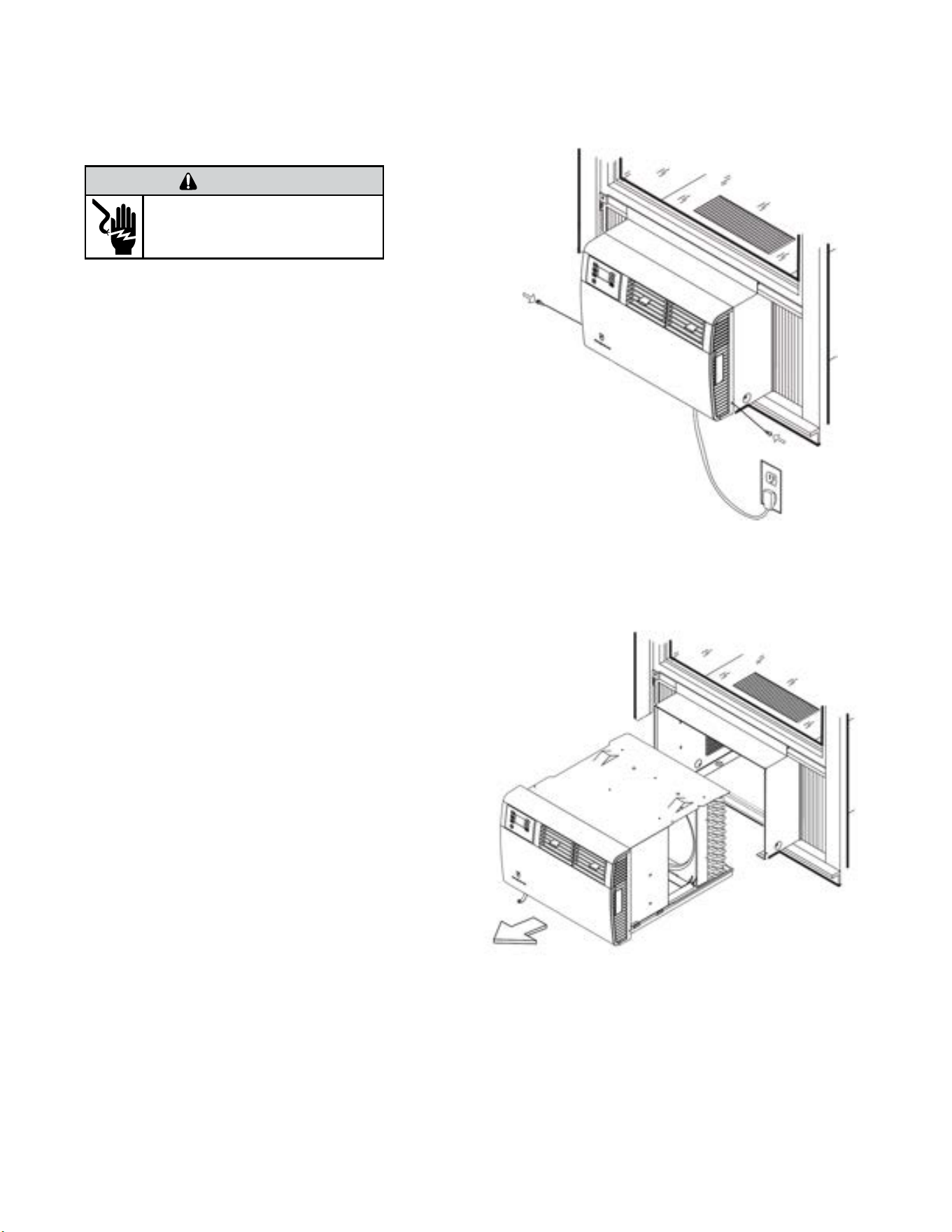
54 54
Remove the chassis
1. Remove the EntryGard™ Screws. (Refer to Figure 426)
2. Hold the cabinet stationary then carefully slide the unit out of
the sleeve. Make sure to fully support the unit. (Refer to Figure
417)
Install the Chassis
1. Carefully team lift the chassis and set it into the cabinet. (Refer
to Figure 427)
2. Slide the chassis into the cabinet
4. Reinstall the EntryGard™ screws.. (Refer to Figure 426)
WARNING
ELECTRIC SHOCK HAZARD
Disconnect power to the unit before
servicing. Failure to follow this warning
could result in serious injury or death.
Figure 427 (Remove Chassis)
Figure 426 (Remove Entry Gard Screws)
REMOVE AND INSTALL THE CHASSIS
Kuhl Q
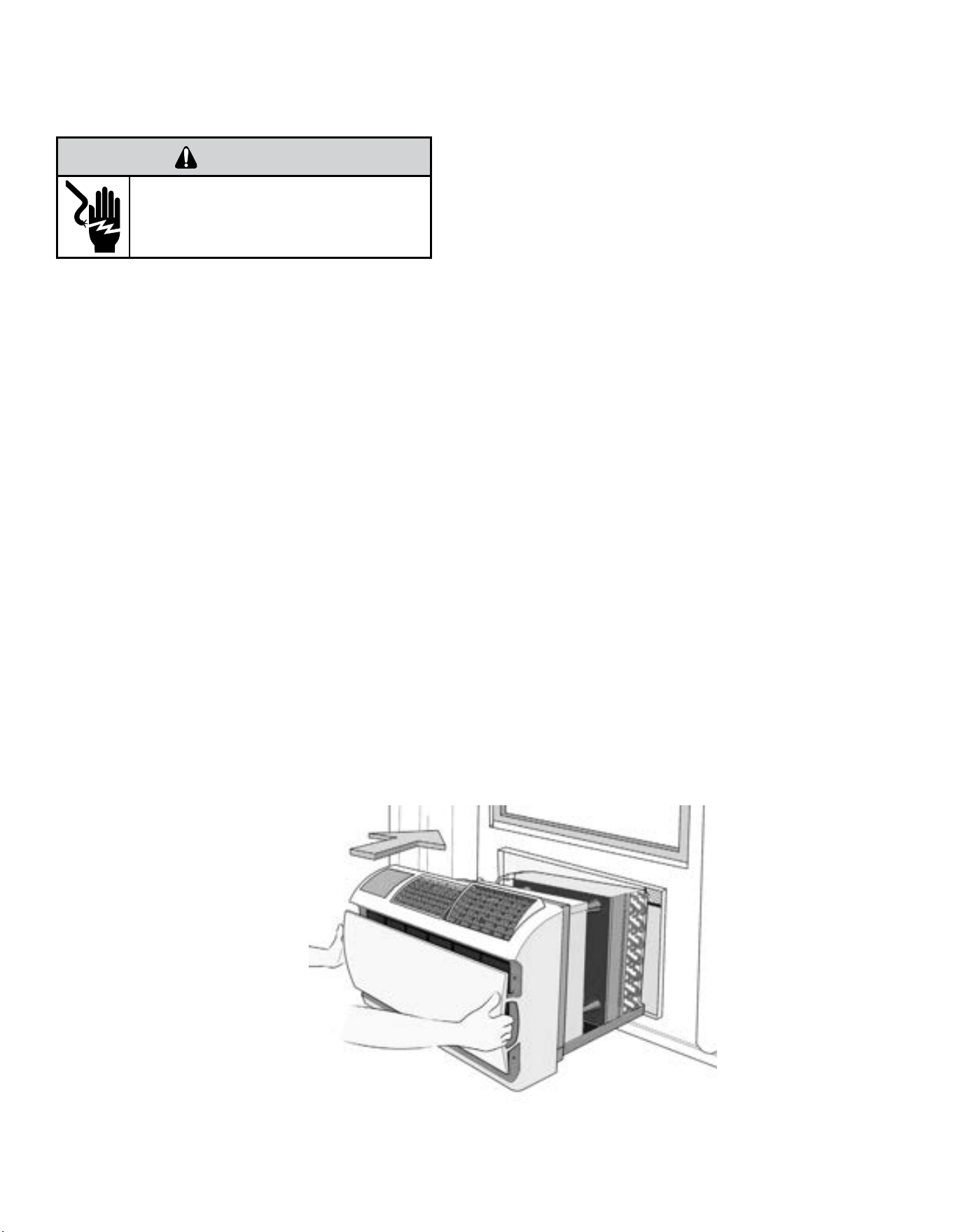
55 55
REMOVE AND INSTALL THE CHASSIS
Wallmaster
Remove Chassis
1. Unplug the unit..
2. Remove the front grill. See Routine Maintenance Figure 403.
3. Remove the clamped drain hose from the nipple if installed.
4. Hold the cabinet stationary then use the hand grips on both ends of
the decorative front assembly to pull the chassis out of the cabinet .
Note: If Ground wire is screwed into the Sleeve, disconnect before
attempting to pull unit all the way out..
Reinstall Chassis
1. Check the sleeve to be certain it has been correctly installed in the wall.
Remove the front panel on the WSE SLEEVE. Remove the rear WEATHER
PANEL. Reverse grille. Place lower edge into sleeve tab (Friedrich logo
facing out). Align slots with the screw holes. Secure grille with screws.
A. Check the anchor screw. There should be four (4) in the WSE
SLEEVE (two in each side).
B. Determine if the sleeve has a downward slope of 3/8 bubble to
the outside..
C. Check to be sure the sleeve has been sealed around all edges
with an industrial type caulking on both the outside and inside to
prevent rain entry.
2. Check the electrical receptacle to see that it conforms to the requirements
for the chassis model to be installed. See figure 207 for the receptacle
requirements.
3. Remove the chassis from the shipping carton.
4. Remove the FRONT PANEL. Using the handles, pull panel out until it is
released from the two retaining snaps. Place the cover aside carefully.
5. Lift the chassis by the basepan and slide it into the front of the sleeve.
(Obtain assistance as needed.)
6. Turn the unit at an angle to allow clearance to secure the grounding wire
which has a red tag on it. Drive a grounding screw through the lug
on the grounding wire, through the wall sleeve, and into the wall
frame.
7. Push the chassis all the way into the sleeve, using the plastic front handles,
so that the front panel meets the front edge of the shell.
NOTE: Chassis comes with pre-installed seal gasket.
8. Check that filter is properly installed, and reinstall front panel.
WARNING
ELECTRIC SHOCK HAZARD
Disconnect power to the unit before
servicing. Failure to follow this warning
could result in serious injury or death.
Figure 428 (Remove and Install the Chassis)
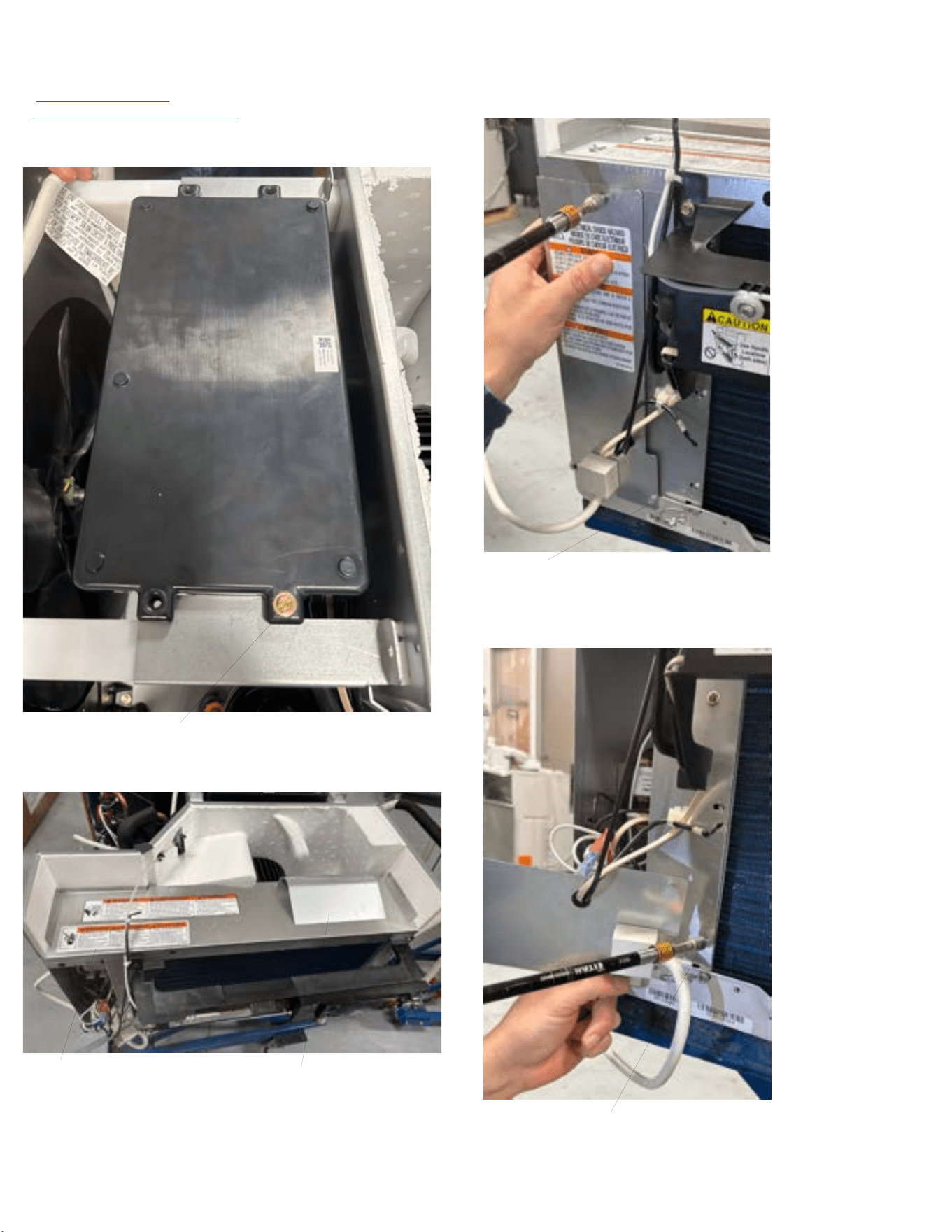
56 56
DISASSEMBLY
Kuhl-Open Electrical Box (To access Power Cord and Fixed Orifice)
1. Remove the front cover.
2. Remove the chassis from the sleeve.
3. Remove 4 screws holding PCB assy to brackets. Slide PCB assy back to ac-
cess electrical box cover screws. See figure 501.
Remove top screws (4 places)
Figure 501
4. Remove Air Foil and top cover. See Figure 502.
Top Cover
Airfoil
Figure 502
4. Remove electrical box cover (3 screws). See figure 503.
Remove Screws (3 Places)
Figure 503
5. Remove 3 screws holding box to evaporator coil. See figure 504
Evaporator screws (3 places)
Figure 504
6. Snip the zip ties holding the hp switch wiring and the indoor coil sensor.
7. Remove indoor coil sensor from evaporator.
8. When reinstalling be sure grommet is correct.
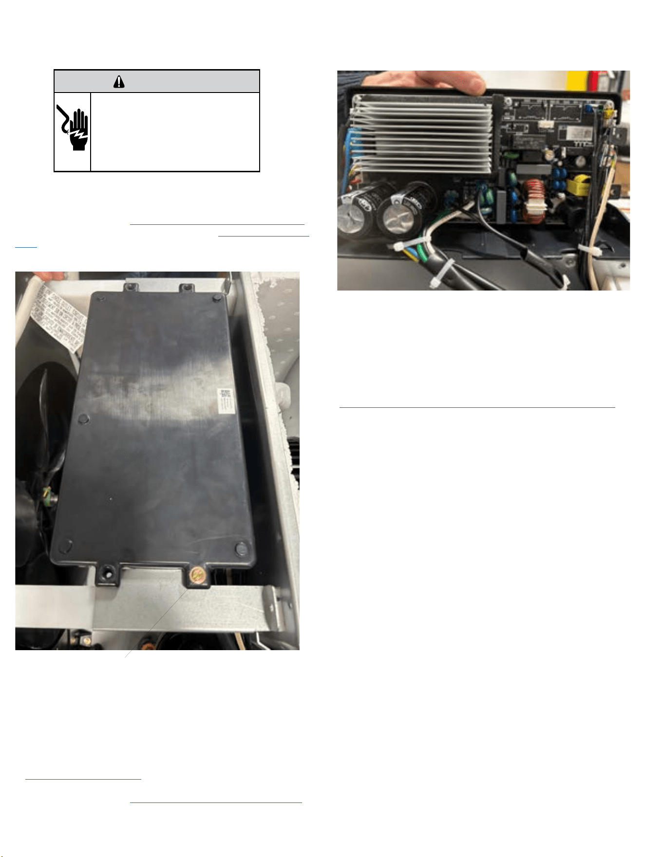
57 57
COMPONENT TESTING
Replace the Main PCB (Kuhl)
WARNING
ELECTRIC SHOCK HAZARD
Turn off electric power before service or
installation. Extreme care must be used, if it
becomes necessary to work on equipment with
power applied.
Failure to do so could result in serious injury or
death.
1. Unplug the unit
2. Remove the Front Cover. Refer to Routine Maintenance, Figure 401.
3. Remove the chassis from the sleeve. Refer to Remove The Chassis-
Kuhl.
3. Remove three (4) screws from Control Box Panel .(See Figure 712
Remove top screws (4 places)
Figure 712
4. The top cover will remain attached to the PCB. Separate from the
bottom tray and rotate the PCB assembly up. See Figure 713.
5. Swap wires one for one from old PCB to new PCB. If swapping wires
one for one is not possible, identify and tag wires.
6. Place PCB back in the bottom tray and reinstall the 4 screws.
7. Ensure wiring is routed correctly and replace any zip ties that were
cut.
8. Reinstall the Chassis - Kuhl.
9.. Install the Front Cover. (Refer to Routine Maintenance, Figure 401.
10. Plug in the unit and test the unit for proper operation. Refer to
operation section.
Figure 713
Replace the User Interface
1. Unplug the Unit
Remove the Front Cover. Refer to Routine Maintenance, Figure 401.
2. Remove 2 –mounting screws securing UI and disconnect ribbon cable.
3. Inspect ribbon cable for obvious signs of damage.
4. If ribbon cable is damaged, or damage is suspected, disconnect cable
from User Interface and PCB. Refer to Replace the Main PCB for ribbon
cable connection.
5. Paying careful attention to the ribbon cable routing, remove the old
cable and replace with a new ribbon cable.
5. Connect ribbon cable to the main PCB and user interface as required.
6. Install new UI using the 2-screws.
7. Plug in the unit and verify control operation. Refer to Operation
Section.
61 61
Room Air Conditioner Unit Performance Test Data Sheet
JOB NAME______________________ TECH’S NAME_________________________
DATE___________ MODEL#_______________ SERIAL #______________________
CHECK THE INSTALLATION
ACCEPTABLE NOT ACCEPTABLE
YES NO
IS A CHASSIS GASKET INSTALLED? _____ ____
IS THE FRESH / EXHAUST AIR VENT OPEN? _____ ____
IS A FRIEDRICH SLEEVE INSTALLED? _____ ____
IS A FRIEDRICH OUTDOOR GRILLE INSTALLED? _____ ____
IS MAINTENANCE BEING PERFORMED? _____ ____
ELECTRICAL
LINE VOLTAGE (STATIC) _____ VOLTS
START UP VOLTAGE _____ VOLTS
AMPERAGE DRAW (COOL) _____ AMPS
AMPERAGE DRAW (HEAT) _____ AMPS
COMPRESSOR
RUNNING AMPERAGE DRAW _____ AMPS
INDOOR CONDITIONS
INDOOR AMBIENT TEMPERATURE _____ F
RELATIVE HUMIDITY (RH) INDOOR _____%
DISCHARGE AIR TEMPERATURE (INDOOR)(COOL) _____F
DISCHARGE AIR TEMPERATURE (INDOOR)(HEAT) _____F
RETURN AIR TEMPERATURE (INDOOR)(COOL) _____F
RETURN AIR TEMPERATURE (INDOOR) (HEAT) _____F
OUTDOOR TEMPERATURE
OUTDOOR AMBIENT TEMPERATURE _____F
RH OUTDOOR RELATIVE HUMIDITY _____%
DISCHARGE AIR TEMPERATURE (OUTDOOR)(COOL) _____F
DISCHARGE AIR TEMPERATURE (OUTDOOR)(HEAT) _____F
INTAKE AIR TEMPERATURE (OUTDOOR)(COOL) _____F
INTAKE AIR TEMPERATURE (OUTDOOR)(HEAT) _____F
COOLING OR HEATING AREA
AREA W______ * L_______ = FEET SQUARED
FOR A GENERAL GUIDE REFER TO SIZING GUIDE TO THE RIGHT
FOR EXACT LOAD CALCULATIONS CONSULT MANUAL J OR M.
Cooling Sizing Guide
AREA TO BE
CONDITIONED
IN SQ. FT.
APPROXIMATE
COOLING BTU
REQUIRED
100 - 150 5000
150 - 250 6000
250 - 300 7000
300 - 350 8000
350 - 400 9000
400 - 450 10000
450 - 550 12000
550 - 700 14000
700 - 1000 18000
1000 - 1200 21000
1200 - 1400 23000
1400 - 1500 24000
1500 - 2000 30000
2000 - 2500 34000
Guide based on normal
room insulation, average
number of sun exposed
windows and two person
occupancy.
1. If heavily shaded, reduce
cooling Btus required by 10%
2. If very sunny, increase cool-
ing Btus required by 10%
3. Add 500 Btus per person over
2 people
4. Add 4,000 Btus if the area is
a kitchen
TROUBLESHOOTING
Figure 601 (Test Data Sheet)
Figure 602 (Cooling Sizing Guide)
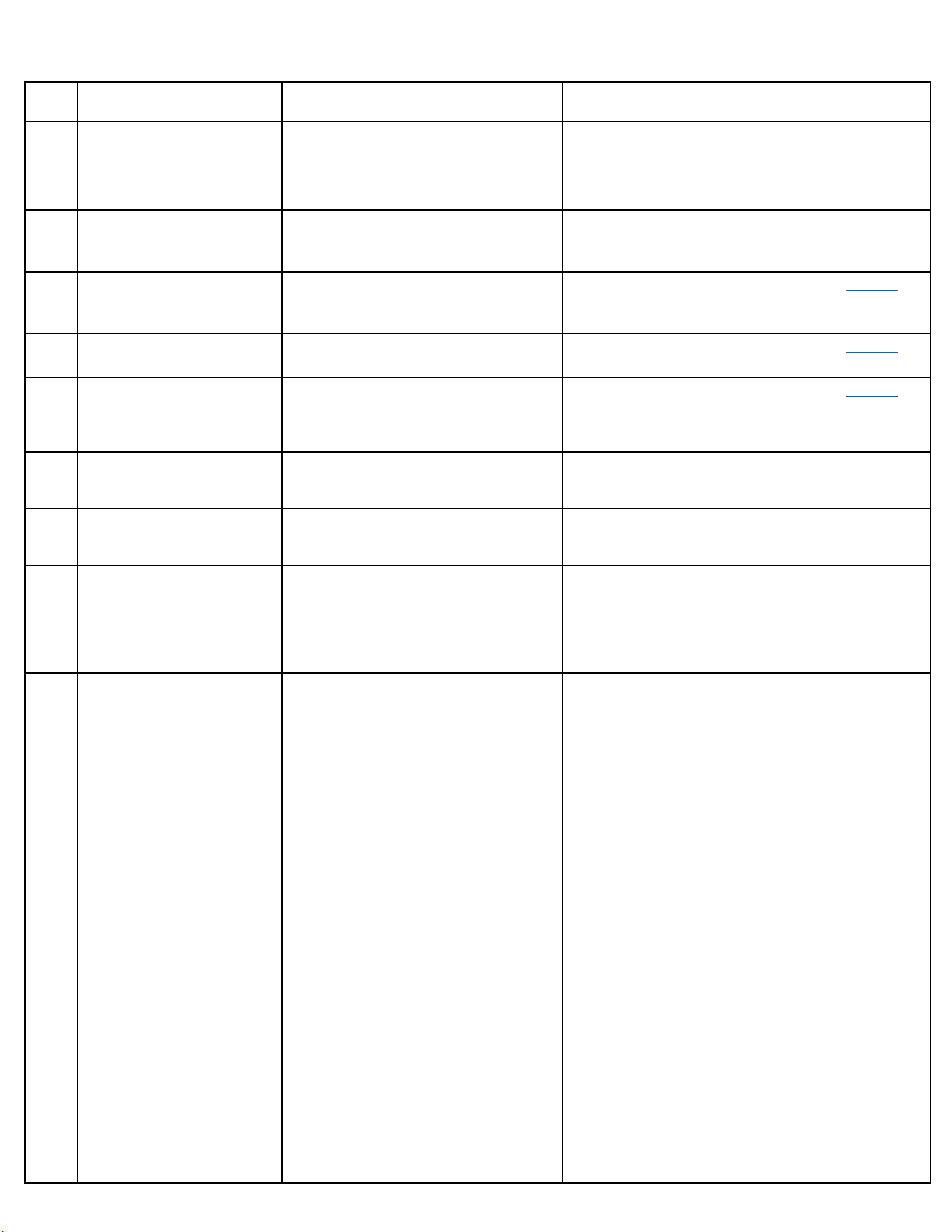
62 62
DIAG
CODE
PROBLEM DESCRIPTION CORRECTIVE ACTION
1
Front Panel Button Stuck For
More Than 20 Seconds.
1. Ensure front cover does not depress buttons.
2. Check wiring connections from UI to Inverter board.
3. Replace UI and Cable.
4. Replace Inverter Board.
2
Inverter firmware check. Active when firmware version is less than the
desired version number.
Contact Customer Support.
3
Indoor Temperature Sensor is
Open or Shorted.
Unit will set temp to 75°F in COOLING or 68°F
in HEATING. Unit continues to operate.
Check for open or shorted temp sensor. Refer to Appendix for
temp. sensor values.
4
Indoor Coil Temperature Sensor
is Open or Shorted.
Control Board sets temp to a default of 40°F.
Override sensor. Unit continues to operate.
Check for open or shorted temp sensor. Refer to Appendix for
temp. sensor values.
5
Outdoor Coil Temperature
Sensor is Open or Shorted.
Unit sets temp to 20° F. and overrides sensor.
Operation continues. Unit uses electric heat if
available for heating. If not available uses heat
pump if outdoor temp allows.
Check for open or shorted temp sensor. Refer to Appendix for
temp. sensor values.
6
Outdoor Coil greater than 175° F. Unit turns compressor off. Waits for the
outdoor coil to be less than 150° F for more
than 2 consecutive minutes.
7
Indoor Coil less than 30° F for 2
consecutive minutes.
Unit turns compressor and electric heat off.
Operation resumes after lockout time or when
coil temp reaches 45°f.
8
Unit Cycles greater than 9 Times
per hour.
Unit continues operation.
Unit is oversized for the space.
Windows or doors to the outside are open.
3. Operating in Cooling mode while the outside
temperature is below 60 °F (16 °C).
1. Check the cooling capacity of your unit to ensure it is
properly sized for the room in which it is installed. Room air
conditioners are not designed to cool multiple rooms.
2. Ensure that all windows and doors are closed.
9
Unit Cycles less than 3 Times per
Hour.
Unit continues operation.
1. Unit is undersized for the space. (The air
conditioner has insufficient cooling capacity to
match the heat gain or loss of the room.)
2. Unit is undersized for the space. (The air
conditioner has insufficient heating capacity to
match the heat loss of the room.)
3. The return/ discharge air grille is blocked.
4. The filter is dirty or obstructed.
5. The indoor coil or outdoor coil is dirty or
obstructed.
6. There is excessive heat or moisture
(cooking, showers, etc.) in the room.
7. The temperature of the room you are trying
to cool is extremely hot or cold.
8. The digital control is set to fan cycling mode.
9. The temperature is not set at a cool
enough/ warm enough setting.
10. This may be due to an excessive heat load
in the room.
1. Check the cooling capacity of your unit to ensure it is
properly sized for the room in which it is installed. Room air
conditioners are not designed to cool multiple rooms.
2. Check the heating capacity of your unit. Air conditioners are
sized to meet the cooling load, and heater size is then selected
to meet the heating load. In extreme northern climates, room
air conditioners may not be able to be used as a primary
source of heat.
3. Ensure that the return and/ or discharge air paths are
not blocked by curtains, blinds, furniture, etc. Remove
obstructions.
4. Clean the filter, (see Routine Maintenance), or remove
obstruction.
5. Clean the coils, (see Routine Maintenance), or remove
obstruction.
6. Be sure to use exhaust vent fans while cooking or bathing
and, if possible, try not to use heat producing appliances
during the hottest part of the day.
7. Adjust the Temperature control to a cooler or warmer
setting as necessary. Allow additional time for the air
conditioner to cool off a very hot room.
8. Since the fan does not circulate the room air continuously
at this setting, the room air does not mix as well and hot (or
cold) spots may result. Using the continuous fan setting is
recommended to obtain optimum comfort levels.
9. Adjust the Temperature control to a cooler or warmer
setting as necessary.
10. If there are heat producing appliances in use in the room,
or if the room is heavily occupied, the unit will need to run
longer to remove the additional heat.
TROUBLESHOOTING
Diagnostic Codes
Figure 603
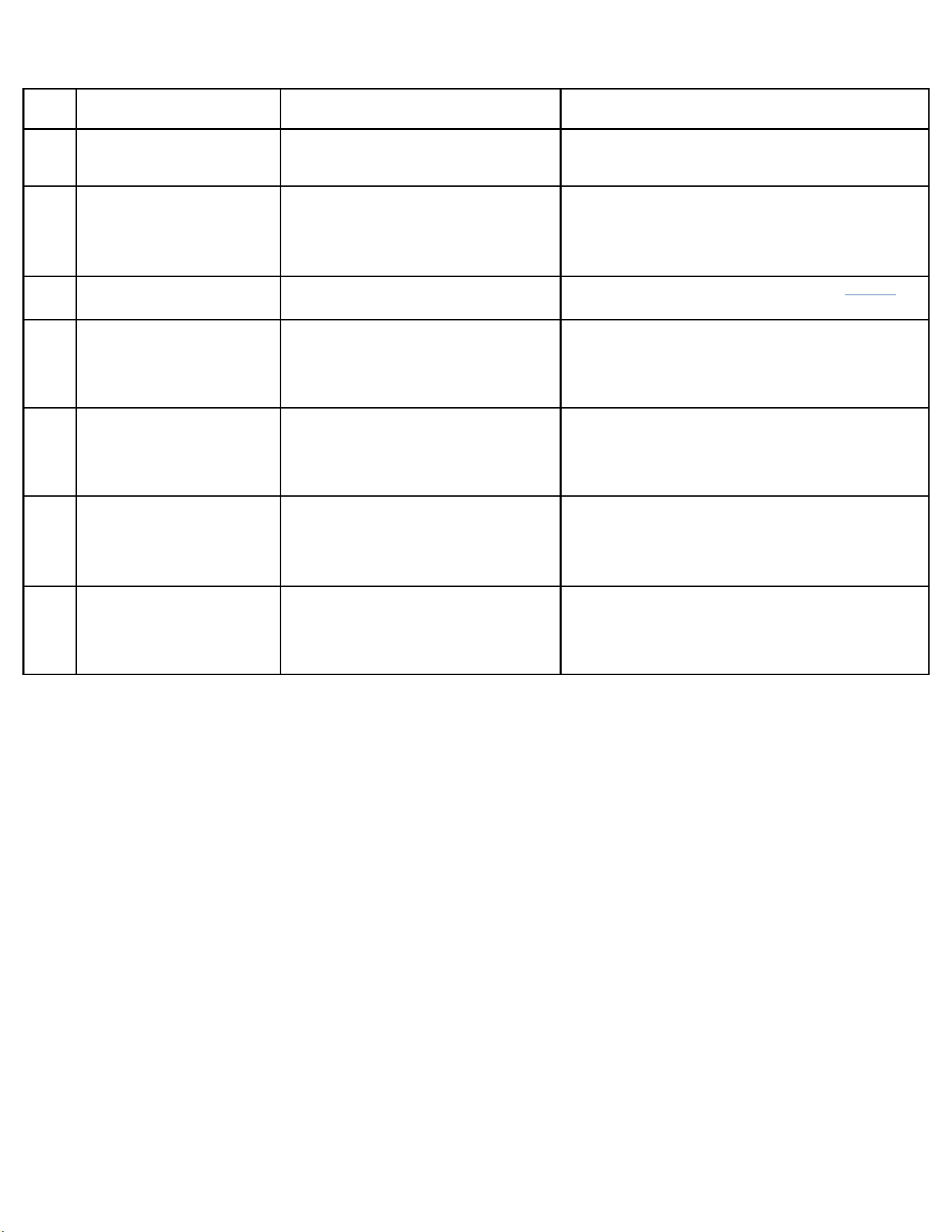
63 63
TROUBLESHOOTING
Diagnostic Codes
DIAG
CODE
PROBLEM DESCRIPTION CORRECTIVE ACTION
12
Discharge Air greater than
185°F.
Unit Shuts down electric heater. When
discharge air temperature is less than 100°F.
operation resumes.
13
High Pressure Switch Open. Unit shuts down compressor. Operation
resumes after lockout time and pressure
switch closes.
1. With unit power off, disconnect terminal pins of HPS1 and
ohm check to see if circuit is open.
2. If open replace HP switch.
3. If closed check for restriction in refrigeration system
causing high pressure.
14
Discharge Air Temperature
Sensor is Open or Shorted.
Unit overrides sensor and sets temp to 75°F.
Check for open or shorted temp sensor. Refer to Appendix for
temp. sensor values.
15
Inverter communication lost. No communication with inverter board 1. Check wiring from UI to inverter board.
2. Replace UI and cable.
3. Replace Inverter board.
16
Temperature Beyond Operating
Limits.
Ambient temp is less than 0°F or greater than
130°F. Unit turns off compressor, electric
heat, and fan. Operation resumes after fault is
cleared.
Do not operate unit outside of maximum conditions.
22
Outdoor Coil Temperature less
than 30°F for 2 consecutive
Minutes .
Only applicable to units with heat pump
and electric heat. Unit turns off heat pump
operation. Uses electric heat to satisfy all
heating demands. Cleared when outdoor coil
temp is greater than 45°F.
23
Frost Protection. Only applicable to heat pump only units. Active
when Heat Pump run time exceeds 60 minutes
with the outdoor coil temp less than 26°F.
Runs active defrost for up to 6 minutes.
Figure 603
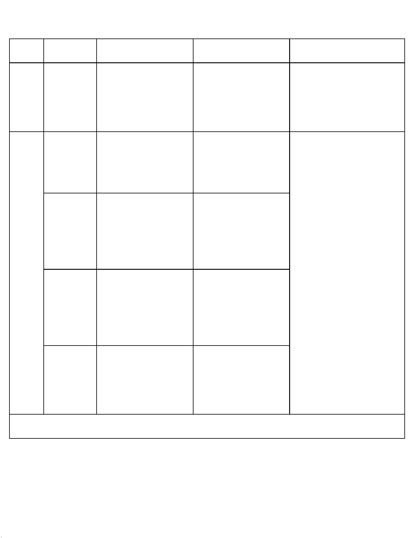
64 64
DIAG
CODE
PROBLEM
CONDITIONS POSSIBLE CAUSES CORRECTIVE ACTION
17
Inverter fan fault The feedback signal of outdoor fan
cannot be detected.
1. Start detection when the ODU fan
is running.
2. The feedback signal of outdoor
fan cannot be detected.
3. If the above conditions are
met. the unit will shut down for 3
minutes, error will be reported.
1. Fan blade is stuck.
2. PCB and motor unconnected.
3. PCB is faulty.
4. DC fan motor is faulty.
1. Remove object from condenser fan or
evaporator blower wheel.
2. Check wiring and connections between
motor and PCB.
3. Replace Inverter board PCB.
4. Replace Fan motor.
18
Inverter
immediate
fault 1
7810
Loss of
Compressor Motor
Control
Loss of Compressor Motor Control.
1. Detects the fault when the
compressor is running;
2. PCB detected abnormal operation
of compressor.
3 If the above conditions are
met, the unit will shut down for 3
minutes, and error will be reported.
1. PCB and Compressor disconnected.
2. PCB is faulty.
3. Compressor is faulty
1. Check wiring and connections from PCB to
compressor.
2. Disconnect the compressor before power up
the unit and check for fault. If fault is removed
replace compressor.
3. Check the voltage of power supply.
4. Check the radiator ventilation is normal.
5. Check whether the IPM is in good contact with
the radiator.
6. Check refrigeration system for abnormalities.
7. Replace Inverter PCB.
8. Replace Compressor.
For loss of compressor motor control,
compressor startup faults, and compressor
phase overcurrent see figure 607.
7813
Compressor
Startup Fault
Compressor start failure.
1. Start detection when compressor
starts;
2. A start failure is detected and the
system starts again after a delay
of 20s;
3. If the start-up fails for three
consecutive attempts. The unit will
be shut down for 3 minutes. Error
will be reported.
1. PCB and Compressor disconnected.
2. System abnormal.
3. PCB is faulty.
4. Compressor is faulty
7800
Compressor Phase
Over Current
The compressor current exceeds
the set software limit value.
1. Detect the fault when the
compressor is running;
2. The compressor Peak current
is detected to exceed the set limit
value.
3. If the above conditions are
met. the unit will shut down for 3
minutes, and error will be reported.
1. PCB and Compressor disconnected.
2. System abnormal.
3. PCB is faulty.
4. Compressor is faulty
7801
AC Input Over
Current
The AC RMS current is detected to
exceed the set limit value.
1. Detect the fault when the
compressor is running.
2. The AC RMS current is detected
to exceed the set limit value.
3. If the above conditions are
met. the unit will shut down for 3
minutes, and error will be reported
1. Supply voltage is unstable.
2. The system is overloaded due to
poor heat dissipation
See following page for continuation of fault code 18.
TROUBLESHOOTING
Diagnostic Codes-Inverter
Figure 604
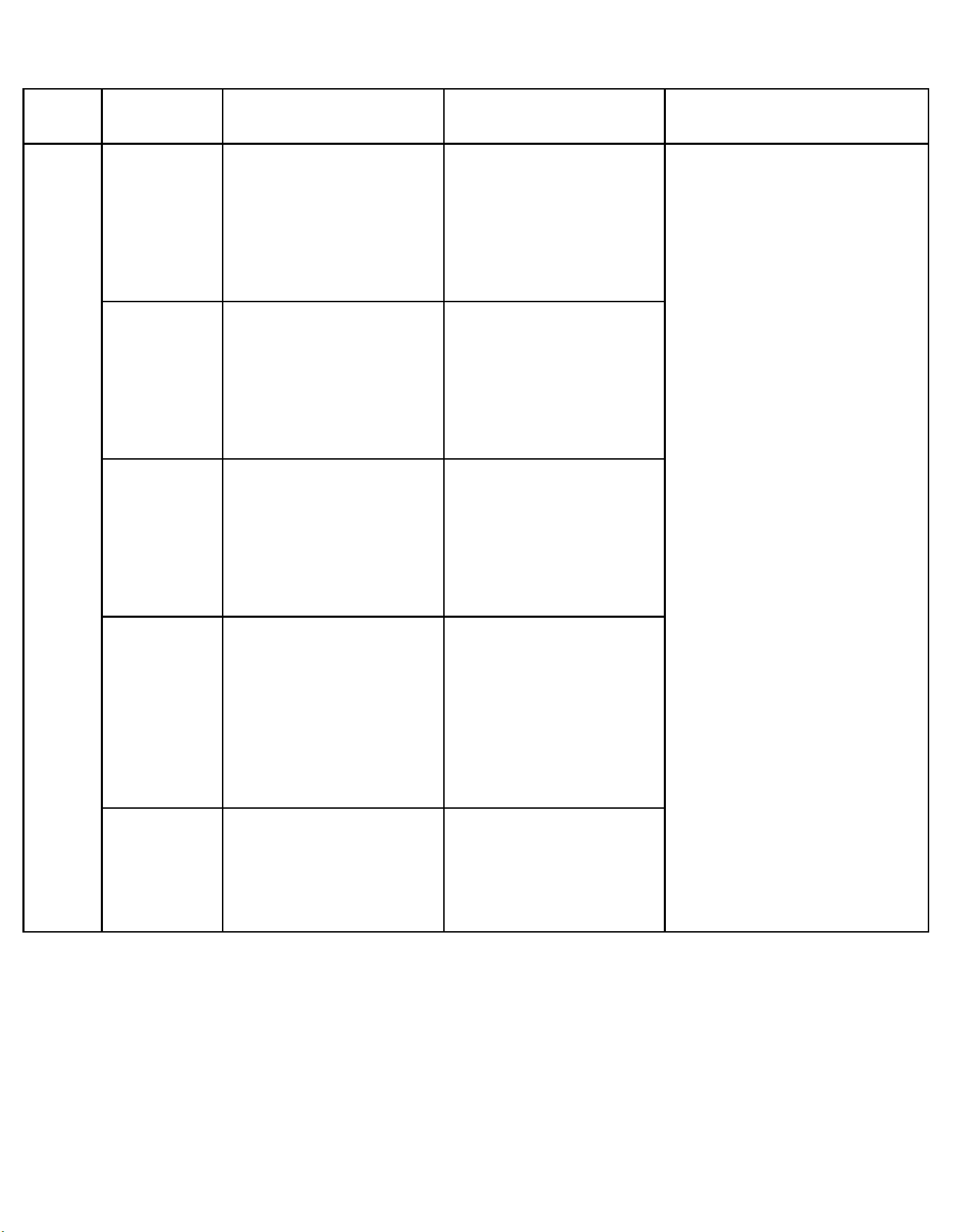
65 65
DIAG
CODE
PROBLEM
CONDITIONS POSSIBLE CAUSES CORRECTIVE ACTION
18 (CONT)
Inverter
immediate
fault 1
Continued
7802
DC Bus Over
Voltage
The DC voltage on the electrolytic
capacitor exceeds the set limit value
1. After power is on.
2. The DC voltage on the electrolytic
capacitor exceeds the set limit
value.
3. If the above conditions are met. it
will report the fault to Display Board
for 3 minutes continuously.
1. The voltage of power supply is
too high.
1. Power supply voltage > 230 VAC
for 115 V power. 300 VAC for 230V
power.
1. Check wiring and connections from PCB to
compressor.
2. Disconnect the compressor before power up
the unit and check for fault. If fault is removed
replace compressor.
3. Check the voltage of power supply.
4. Check the radiator ventilation is normal.
5. Check whether the IPM is in good contact with
the radiator.
6. Check refrigeration system for abnormalities.
7. Replace Inverter PCB.
8. Replace Compressor.
7803
DC Bus Under
Voltage
The DC voltage on the electrolytic
capacitor is lower than the set limit
value.
1. After power is on.
2. The DC voltage on the electrolytic
capacitor exceeds the set limit value
3. If the above conditions are met. it
will report the fault to Display Board
for 3 minutes continuously.
1. The voltage of power supply is
too low.
1. Power supply voltage < 78 VAC
for 115V power. 120 VAC for 230V
power.
2. PCB is faulty.
7811
Compressor
Power Module
Over Temperature
IPM module temperature exceeds
the set limit value.
1. Detect the fault when the
compressor is running;
2. IPM module temperature exceeds
the set limit value.
3. If the above conditions are
met. the unit will shut down for 3
minutes, error will be reported.
1. The radiator ventilation is
abnormal
2. Poor contact between IPM and
radiator or screws are loose.
3. PCB is faulty.
7815
Pre-Charge Relay
Open
This fault occurs when the voltage
between DC + and DC -is lower than
100V when power on for the first
time.
1. Detection at initial power on of
ODU;
2. the voltage between DC + and DC
-is lower than 100V.
3. If the above conditions happed,
error will be reported, and unit will
be shut down.
1. The voltage of power supply is
too low. Power supply voltage
< 70 VAC;
2. PCB is faulty.
7807
PFC Desaturation
1. Detect the fault when the PFC is
on.
2. The AC Peak current is detected
to exceed the set limit value.
3. If the above conditions are
met. the unit will shut down for 3
minutes, error will be reported.
1. The voltage of power supply is
too low or too high.
2. Wiring loose or disconnected.
3. Inverter PCB Faulty.
TROUBLESHOOTING
Diagnostic Codes-Inverter
Figure 604
66 66
DIAG
CODE
PROBLEM
CONDITIONS POSSIBLE CAUSES CORRECTIVE ACTION
19
Inverter
immediate
fault 2
8212
Compressor Module
Over Current
1. Detect the fault when the
compressor is running;
2. The peak current of compressor
exceeds the set hardware limit
value.
3. If the above conditions are
met. the unit will shut down for 3
minutes, error will be reported.
1. AC power out of range.
2. System abnormal.
3. Wiring loose disconnected or in
wrong sequence.
4. PCB faulty.
5. Compressor damaged.
See figure 608
8206
Compressor Model
Configuration
Error
Compressor code showed in display
is out of the setting ranges.
1. Power on the unit.
2. Compressor code showed in
display is out of the setting range.
Wrong compressor code Contact customer support.
20
Inverter
controlled
fault 1
7907
Modbus
Communications
Lost modbus
1. User Interface and Inverter PCB
power on.
2. Display Board cannot receive data
from PCB or received wrong data.
3. Communication errors between the
user interface and the inverter PCB.
4. If the above conditions are met 30s,
error will be reported.
1. Loose or disconnected wiring.
2. User Interface faulty.
3. Inverter PCB faulty.
1. Check for loose, damaged, or disconnected
wiring.
2. Replace User interface.
3. Replace Inverter PCB.
21
Inverter
controlled
fault 2
7913 Unit detects the HPS is open 1. System pressure exceeds the
HPS limits.
2. HPS switch circuit has failed.
1. Determine refrigeration system fault.
2. Check if switch has malfunctioned by
Checking for continuity with no system
pressure.
TROUBLESHOOTING
Diagnostic Codes-Inverter
Figure 604
67 67
Problem Possible Cause Possible Solution
Unit does not operate.
The power button is off or the set point
temperature is satisfied.
Push the power button on and raise or lower temperature setting (as ap-
propriate) to call for operation.
The LCDI power cord is unplugged.
Plug into a properly grounded 3 prong receptacle. (See Electrical Rating
Tables, Figure 206) for the proper receptacle type for your unit.
The LCDI power cord has tripped (Reset
button has popped out).
Press and release RESET (Listen for click. Reset button latches and re-
mains in.) Check that the green LED light is on to resume operation.
The circuit breaker has tripped or the
supply circuit fuse has blown.
Reset the circuit breaker, or replace the fuse as applicable. If the prob-
lem continues, contact a licensed electrician.
There has been a local power failure. The unit will resume normal operation once power has been restored.
Unit Trips Circuit Breaker or
Blows Fuses.
Other appliances are being used on the
same circuit. (115 Volt only)
The unit requires a dedicated outlet circuit, not shared with other appliances.
An extension cord is being used. Do NOT use an extension cord with this or any other air conditioner.
The circuit breaker or time-delay fuse is
not of the proper rating.
Replace with a circuit breaker or time-delay fuse of the proper rating. (See
Electrical Rating Tables, Figure 206) for the proper circuit breaker/ fuse rat-
ing for your unit. If the problem continues, contact a licensed electrician.
LCDI Power Cord Trips
(Reset Button Pops Out).
The LCDI power cord can trip (Reset
button pops out) due to disturbances
on your power supply line.
Press and release RESET (Listen for click. Reset button latches and remains
in.) Check that the green LED light is on to resume normal operation.
Electrical overload, overheating, or cord
pinching can trip (Reset button pops out)
the LCDI power cord.
Once the problem has been determined and corrected, press and re-
lease RESET (Listen for click. Reset button latches and remains in.) to
resume normal operation.
NOTE: A damaged power supply cord must be replaced with a new power supply cord obtained from the product
manufacturer and must not be repaired.
Does not cool or only cools
slightly
Undersized unit Refer to industry sizing chart.
Indoor ambient thermistor open or
shorted
See diagnostic codes and replace thermistor if needed.
Dirty filter Clean as recommended in Owner’s Manual
Dirty or restricted condenser or evapo-
rator coil
Use pressure wash or biodegradable cleaning agent to clean
Poor air circulation
Adjust discharge louvers. Use high fan speed
Fresh air or exhaust air door open
Close doors. Instruct customer on use of this feature
Low capacity - undercharge Check for leak & make repair
Compressor not pumping properly
Check amperage draw against nameplate. If not conclusive, make pressure
test
Unit does not run
Fuse blown or circuit tripped
Replace fuse, reset breaker. If repeats, check fuse or breaker size. Check for
shorts in unit wiring & components.
Loose or disconnected wiring control
board or other components
Check wiring & connections. Reconnect per wiring diagram.
The LCDI power cord has tripped (Reset
button has popped out).
Press and release RESET (Listen for click. Reset button latches and re-
mains in.) Check that the green LED light is on to resume operation.
Evaporator coil freezes up
Dirty filter Clean filter (see Routine Maintenance)
Restricted airflow Check for dirty or obstructed coil. Clean coil (refer to routine Maintenance)
Inoperative thermistor Check Diagnostic Codes. Check Thermistors and replace as necessary.
Short of refrigerant De-ice coil & check for leak
Inoperative fan motor Test fan motor & replace if inoperative
Partially restricted capillary tube De-ice coil. Replace capillary tube
TROUBLESHOOTING
Basic Troubleshooting
Figure 605
68 68
TROUBLESHOOTING
Troubleshooting Tips
Problem Possible Cause Possible Solution
Compressor runs continually &
does not cycle off
Excessive heat load
Unit undersized. Test cooling performance & replace with larger unit if
needed. See sizing chart.
Restriction in line Check for partially iced coil & check temperature split across coil
Thermistor shorted Replace thermistor or electronic control board
Electronic control
board does not turn unit off
Compressor relay contacts stuck Replace electronic control board
Incorrect wiring Refer to appropriate wiring diagrams
Unit undersized for area to be cooled Refer to industry standard sizing chart
Defective thermistor Replace thermistor or electronic control board
Compressor runs for short
periods only.
Incorrect wiring Refer to appropriate wiring diagram
Shorted or incorrect capacitor Test capacitor and replace if needed.
Restricted or low air flow through con-
denser coil or evaporator coil
Check for proper fan speed or blocked coils. Correct as needed.
Compressor running abnormally hot
Check for kinked discharge line or restricted condenser. Refrigerant over-
charge. Check amperage, connections.
Unit does not turn on
No power
Check power supply. Check LCDI plug. Check wire connections. Check if
panel is locked.
Incorrect wiring Refer to appropriate wiring diagram.
Defective thermistor Replace thermistor or electronic control board.
Noisy operation
Poorly installed Refer to Installation Manual for proper installation.
Fan blade striking chassis Reposition - adjust motor mount.
Compressor vibrating
Check that compressor grommets have not deteriorated. Check that com-
pressor mounting parts are not missing.
Improperly mounted or loose cabinet
parts refrigerant tubes
Check assembly & parts for looseness, rubbing & rattling pipes, etc.
Water Leaks into Room
Evaporator drain pan overflowing Clean obstructed drain trough.
Condensation forming underneath base
pan
Evaporator drain pan broken or cracked. Reseal or replace. No chassis
gasket installed. Install chassis gasket.
Poor installation resulting in rain enter-
ing the room
Check installation instructions. Reseal as required.
Condensation on discharge grille
louvers
Dirty evaporator coil. Clean coils (See Routine Maintenance) Environmental
phenomena: point supply louvers upward. Put on high fan.
Chassis gasket not installed Install gasket, per Installation manual.
Downward slope of unit is too steep
inward
Refer to installation manual for proper installation.
Water “spitting” into room
Sublimation:
When unconditioned saturated, outside
air mixes with conditioned air, conden-
sation forms on the cooler surfaces
Ensure that foam gaskets are installed in between window panes & in
between the unit & the sleeve. Also, ensure that fresh air/exhaust vents (on
applicable models) are in the closed position & are in tact.
Downward pitch of installation is too
steep towards back of unit
Follow installation instructions to ensure that downward pitch of installed
unit is no less than 1/4” & no more than 3/8”
Restricted coil or dirty filter
Clean & advise customer of periodic cleaning & maintenance needs of entire
unit
Excessive moisture
Insufficient air circulation thru area to be
air conditioned
Adjust louvers for best possible air circulation
Inadequate vapor barrier in building
structure; particularly floors.
Advise customer
Figure 606
69 69
Problem Possible Cause Possible Solution
Unit short cycles
Defective thermistor Replace thermistor or electronic control board
Unit oversized See sizing chart. Correct as needed.
Chassis seal gasket not sealing or ab-
sent causing unit to short cycle
Check gasket. Reposition or replace as needed
Restricted coil or dirty filter
Clean & advise customer of periodic cleaning & maintenance needs of entire
unit
Prolonged off cycles
Defective indoor ambient thermistor or
electronic control board
Check alarms. Replace thermistor or electronic control board
Outside water leaks
Evaporator drain pan cracked or ob-
structed
Repair, clean or replace as required
Obstructed condenser coil Use pressure wash or biodegradable cleaning agent to clean
Fan blade/ slinger ring improperly
positioned
Adjust fan blade to 1/2” of condenser coil fin pack
Room temperature uneven
(Heating cycle)
Bad indoor ambient thermistor Check diagnostic codes. Check Thermistors. Replace as needed.
Fan speed too low Set at higher fan speed.
Does not heat adequately
Exhaust or fresh air door open Check if operating properly. Instruct customer on proper use of control
Dirty filter Clean (See Routine Maintenance)
Unit undersized
Check heat rise across coil. If unit operates efficiently, check if insulation can
be added to attic or walls. If insulation is adequate, recommend additional
unit or larger one
Heater hi-limit control cycling on & off Check for adequate fan air across heater. Check for open hi-limit control.
Shorted or open supplementary heater Do ohmmeter check.
Incorrect wiring Check applicable wiring diagram
Unit cools when heat is called
for
Incorrect wiring Refer to applicable wiring diagram
Defective solenoid coil Check for continuity of coil
Reversing valve fails to shift
Block condenser coil & switch unit to cooling. Allow pressure to build up in
system, then switch to heating. If valve fails to shift, replace valve.
Cooling adequate, but heating
insufficient.
Reversing valve failing to shift com-
pletely; bypassing hot gas
De-energize solenoid coil, raise head pressure, energize solenoid to break
loose. If valve fails to make complete shift, replace valve.
TROUBLESHOOTING
Troubleshooting Tips
Figure 606
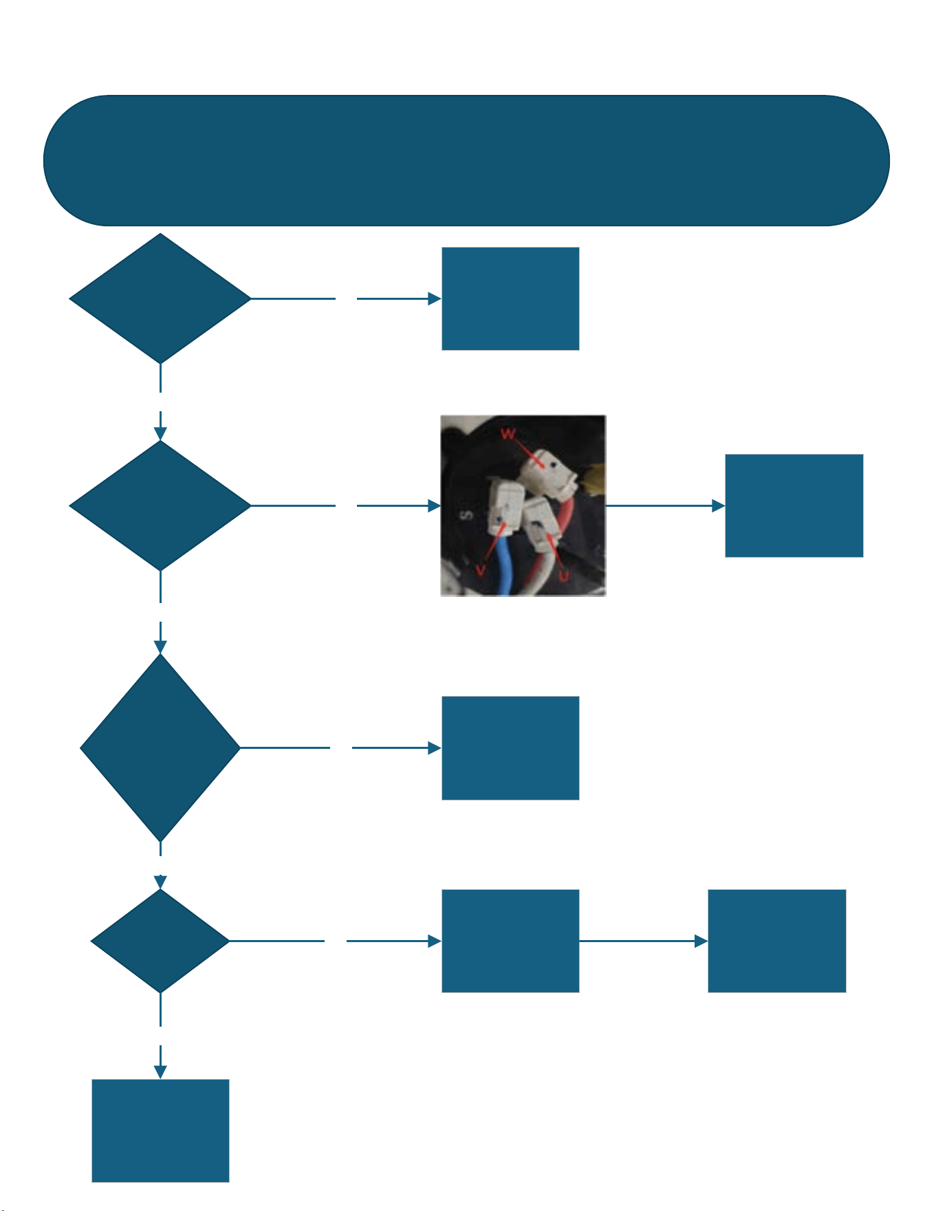
70 70
TROUBLESHOOTING
For loss of compressor motor control, compressor startup faults, and compressor phase overcurrent
Figure 607
FaultCode18:InverterImmediateFault1(7810,7813,7800)
LossofCompressorControl,CompressorStartupFault,
CompressorPhaseOverCurrent)
Arefilerorcoil sdirty
orobstructed
CleanFilterandcoilsYES
Iswiringto
Compressorloose
damaged,or
incorrect?
NO
YES
Repairorcorrect
wiring
Istherea
restrictionorblock
inrefrigeration
system?Pressure
toohigh?
NO
Repairrefrigeration
system
YES
Hascompressor
malfunctioned
Seecompressor
checks
Replaceifithasa
malfunction
NO
YES
ReplaceMainPCB
NO
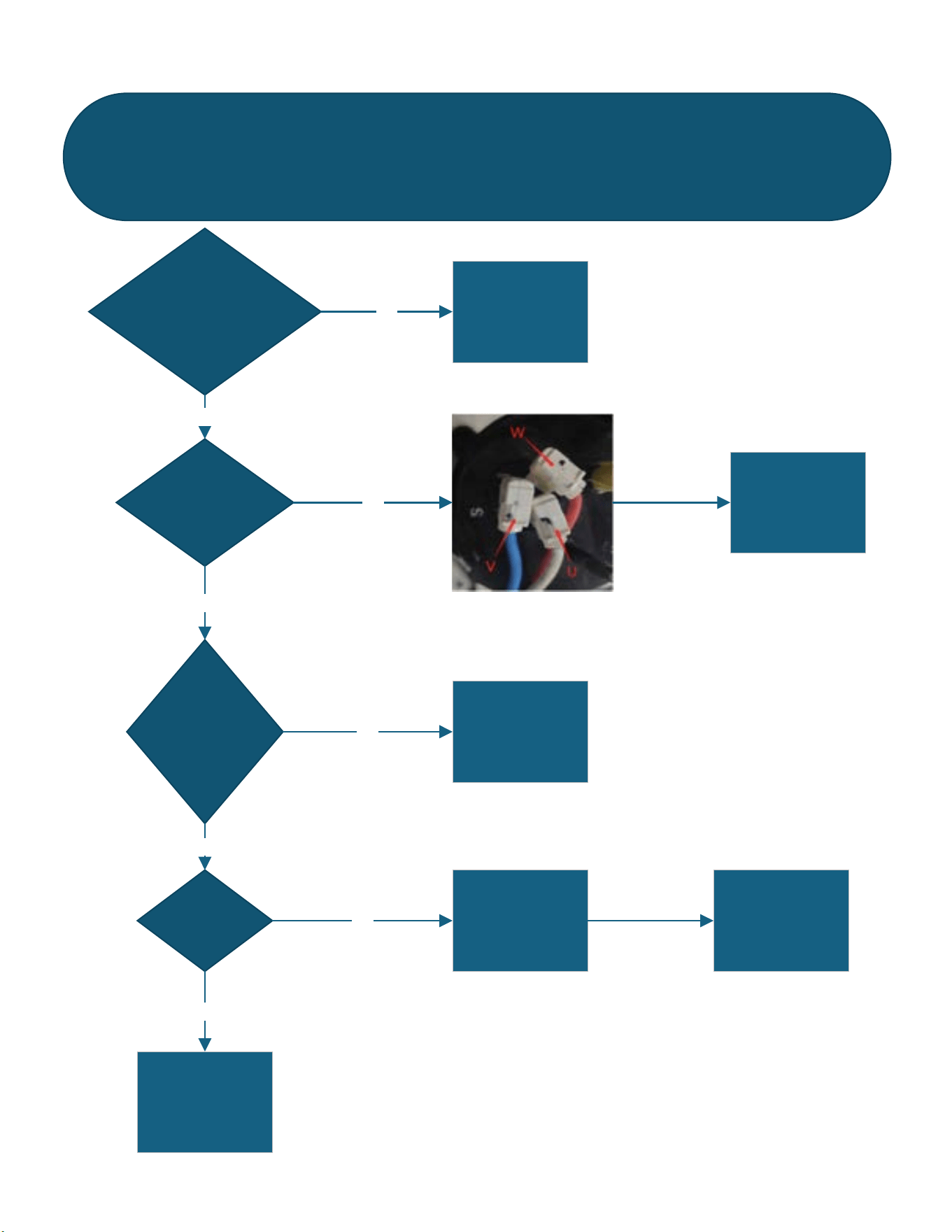
71 71
TROUBLESHOOTING
Compressor Module Over Current
Figure 608
FaultCode19:InverterImmediateFault2(8212)
CompressorModuleOverCurrent
Checktoseeifinputpower
supplyisoutofrange
Addresspower
supplyproblem
YES
Iswiringto
Compressorloose
damaged,or
incorrect?
NO
YES
Repairorcorrect
wiring
Istherea
restrictionorbloc k
inrefrigeration
system?Pressure
toohigh?
NO
Repairrefrigeration
system
YES
Hascompressor
malfunctioned
Seecompressor
checks
Replaceifithasa
malfunction
NO
YES
ReplaceMainPCB
NO
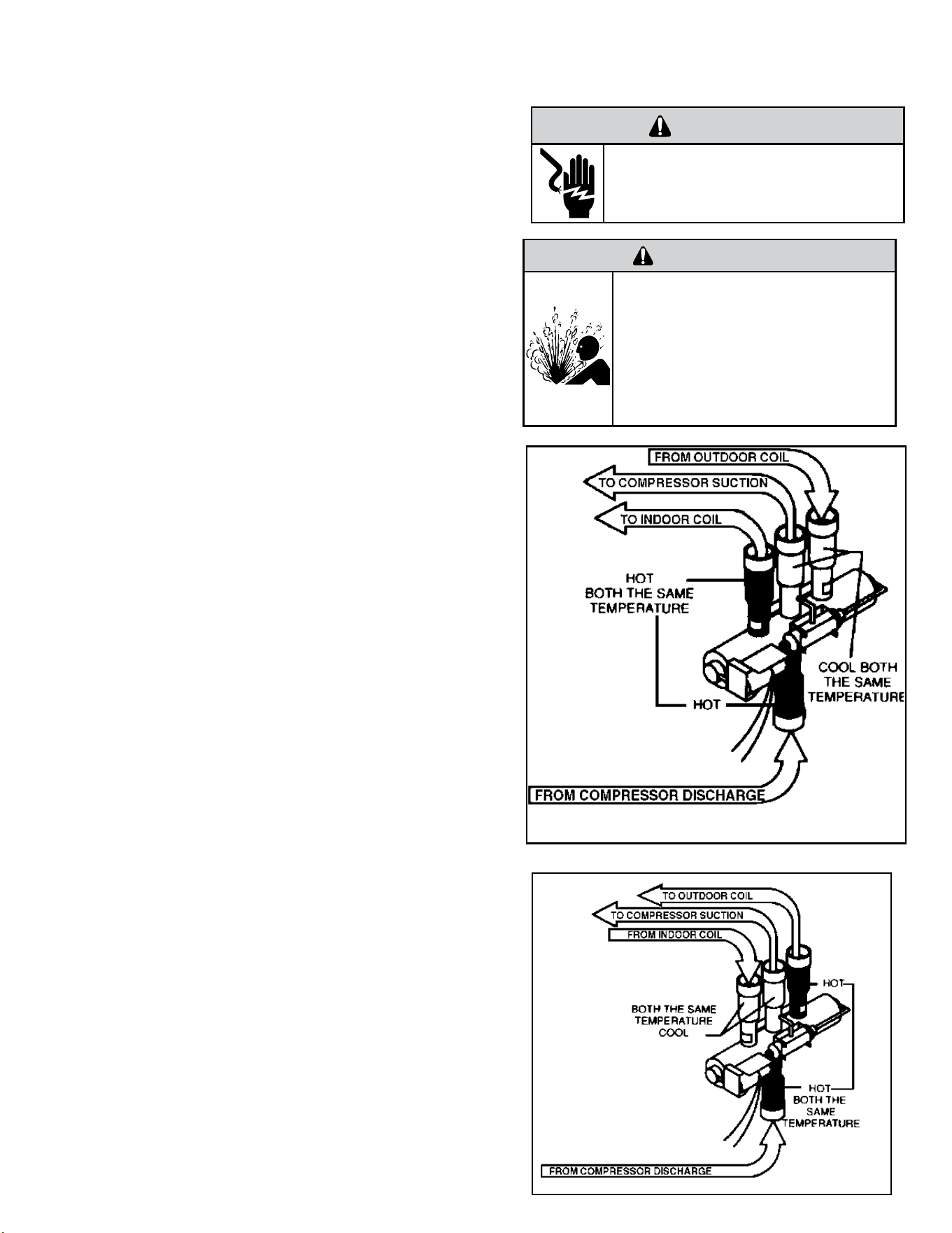
72 72
A reversing valve is a component of a heat pump that changes the direction of
refrigerant flow, allowing the system to function in both heating and cooling
modes.
It consists of a pressure-operated, main valve and a pilot valve actuated
by a solenoid plunger. The solenoid is energized by 24 vac during the
heating cycle only.
The single tube on one side of the main valve body is the high-pressure
inlet to the valve from the compressor. The center tube on the opposite
side is connected to the low pressure (suction) side of the system.
The other two are connected to the indoor and outdoor coils. Small
capillary tubes connect each end of the main valve cylinder to the “A”
and “B” ports of the pilot valve. A third capillary is a common return
line from these ports to the suction tube on the main valve body. Four-
way reversing valves also have a capillary tube from the compressor
discharge tube to the pilot valve.
The plunger assembly in the main valve can only be shifted by the
pressure differential between the high and low sides of the system. The
pilot section of the valve opens and closes ports for the small capillary
tubes to the main valve to cause it to shift.
Checking the Reversing Valve
NOTE: System operating pressures must be near normal before valve
can shift.
NOTE: You must have normal operating pressures
before the reversing valve can shift.
Run the unit in the heating mode then disconnect one of the 24
vac wires at the reversing valve and the valve should shift to
cooling mode. If valve does not shift - replace the valve(verify the
unit is properly charged before replacing valve.) For a stuck valve
diagnosis run in the cooling mode and check the temp difference
between the suction line from the evaporator and the common
suction line at the compressor, if there is more than a 3 ˚F
difference then change the valve.
Checking The Reversing Valve Solenoid
The solenoid coil is an electromagnetic type coil mounted on
the reversing valve and is energized during the operation of the
compressor in the heating cycle.
1. Turn off high voltage electrical power to unit.
2. Unplug line voltage lead from reversing valve coil.
3. Check for electrical resistance through the coil. If the coil is
open replace the coil.
4. Check from each lead of coil to the copper liquid line as it
leaves the unit or the ground lug. There should be no continuity
between either of the coil leads and ground; if there is, coil is
grounded and must be replaced.
5. If coil tests okay, reconnect the electrical leads.
6. Make sure coil has been assembled correctly.
NOTE: Do not start unit with solenoid coil removed from valve,
or do not remove coil after unit is in operation. This will cause
the coil to burn out.
COMPONENT TESTING
Reversing Valve
Reversing Valve in Heating Mode
WARNING
HIGH PRESSURE HAZARD
Sealed Refrigeration System contains refrigerant
and oil under high pressure.
Proper safety procedures must be followed,
and proper protective clothing must be worn
when working with refrigerants.
Failure to follow these procedures could
result in serious injury or death.
WARNING
ELECTRIC SHOCK HAZARD
Disconnect power to the unit before
servicing. Failure to follow this warning
could result in serious injury or death.
Figure 701
Figure 702
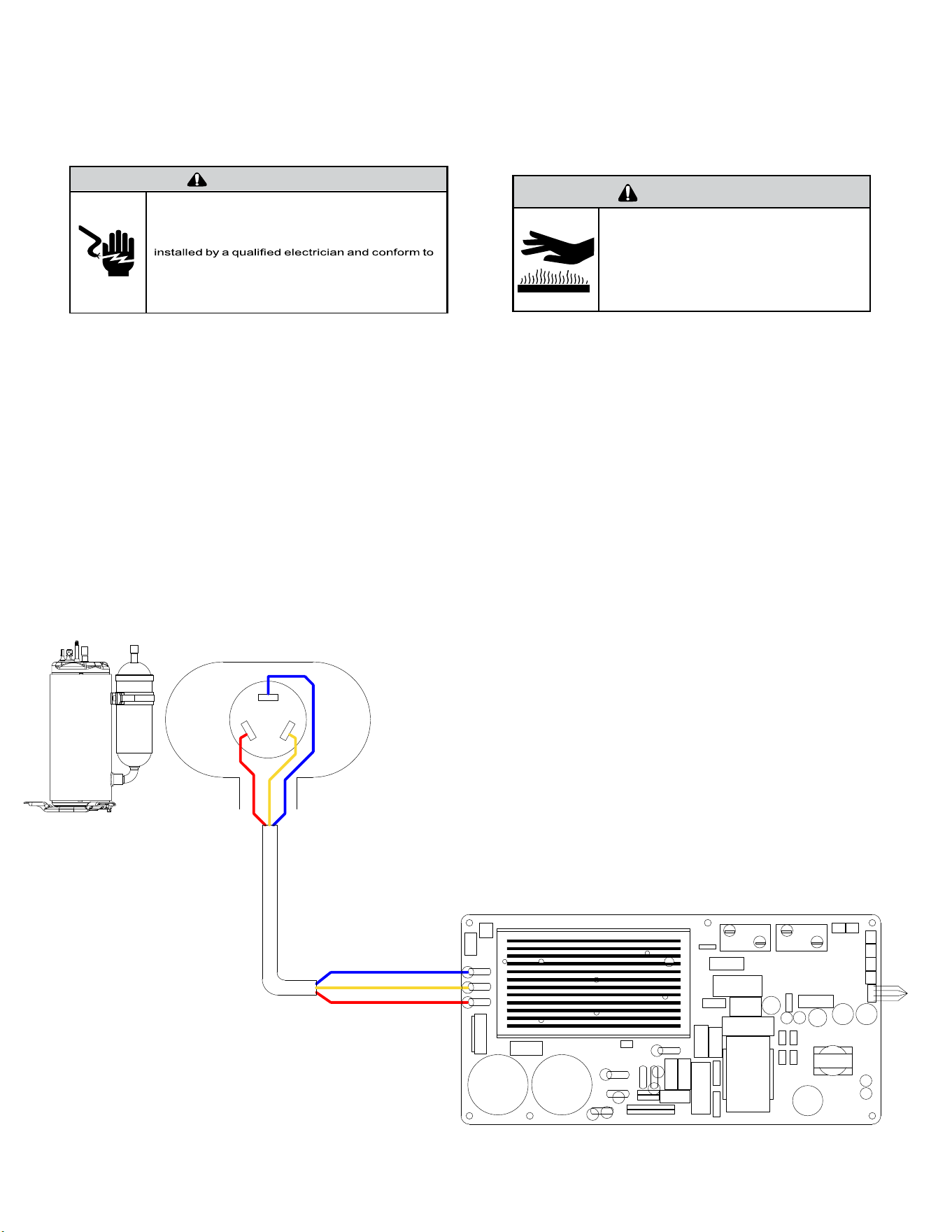
73 73
COMPONENT TESTING
Compressor Checks
WARNING
ELECTRIC SHOCK HAZARD
Turn off electric power before service or
installation.
All electrical connections and wiring MUST be
the National Electrical Code and all local codes
which have jurisdiction.
Failure to do so can result in personal injury or
death.
BURN HAZARD
Proper safety procedures must be followed,
and proper protective clothing must be worn
when working with a torch.
Failure to follow these procedures could
result in moderate or serious injury.
WARNING
Resistance Test.
1. Access the main PCB.
2. Locate and disconnect the motor winding leads shown in the gure
below.
U= Blue V= Yellow W= Red
3. Using an OHM Meter, check resistance from U to V, U to W, and V to to W.
All of the readings should be within 0.1 ohms of each other.
A difference of more than 0.1 ohms indicates that windings may be
damaged and the compressor should be replaced.
NOTE: Actual OHM values may vary due to temperature of the
compressor.
4. Using a MegOhm Meter, check the motor windings for a short to ground.
Measure the resistance of each winding to ground.
A reading of less than 10 Megohms indicates that the motor
windings may be damaged and the compressor should be replaced..
U
W
V
EH2
RELAY
BLU
YEL
RED
U
W
V
RV1
EH1
RELAY
RV1
RELAY
RE-400
RE-401
RV2
L2/N
GND
L1/L
HARNESS
COMP WIRE
Figure 703
74 74
The Fan Motor installed in your Kuhl or Wallmaster unit is a dual shaft bldc
motor driving both the condenser fan and the indoor blower wheel. The
procedure for checking a 115 vac motor is also the same as checking a 230
vac motor.
1. Unplug the unit.
2. Remove front cover. Refer to Routine Maintenance.
4. Remove Chassis from the sleeve.
3.
Turn unit on.
4. Check outdoor fan connector from Driver at J8 as shown in gure below.
There are 5 wires:
No. Color Function Remark
1 Red Vm 310 VDC
2 Black Gnd Ground
3 White Vcc 15 VDC
4 Yellow Vsp 0-6.5 VDC
5 Blue FG 12 pulses per revolution
RESIN PACK BRUSHLESS DC MOTOR
黑
BLA GND
黄
YEL Vsp
白
WHI Vcc
�
RED Vm
M
�
BLU FG
ROTATION
(�向)
ZKSP-129-8-1
DC310V 129W
1300(r/min)
E CL
�
8P
极
CPN:20100020
Q.C.Pass
RoHS
YYYYMMDD
NNNNNN WWZZ
ZKSP-129-8-1
Figure 704 [Motor Nameplate (Typical)]
WARNING
ELECTRIC SHOCK HAZARD
Turn off electric power before service or
installation. Extreme care must be used, if it
becomes necessary to work on equipment with
power applied.
Failure to do so could result in serious injury or
death.
COMPONENTS TESTING
Fan Motor
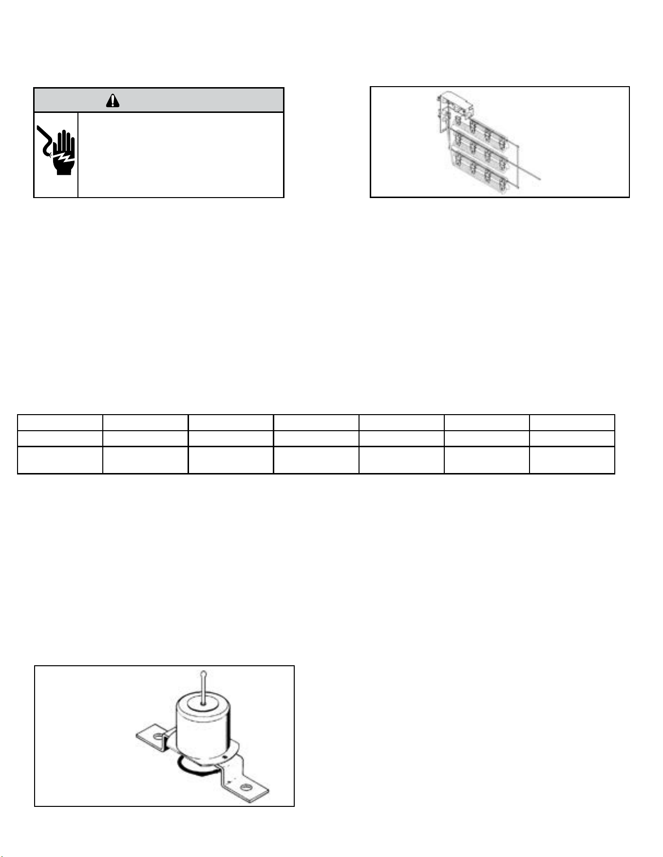
75 75
COMPONENTS TESTING
Heating Element
All heat pumps and electric heat models are equipped with a heating element.
The heating element contains a fuse link and a heater limit switch. The fuse link is in series with the power supply and will open and interrupt the
power when the temperature reaches 199°F or a short circuit occurs in the heating element. Once the fuse link separates, a new heater element
must be installed.
NOTE: Always replace the heating element with the exact replacement.
The heater element has a high limit control. This control is a bimetal thermostat mounted in the top of the heating element.
Should the fan motor fail or lter become clogged, the high limit control will open and interrupt power to the heater before reaching an unsafe
temperature condition.
The control is designed to open at 110°F ±6°F. Test continuity below 110°F or when it is cooled off.
HEATING ELEMENT
The heating element is energized by an outdoor thermistor via the electronic control board. The outdoor defrost thermistor is adjusted at a
predetermined temperature of approximately 30 degrees Fahrenheit and sensed for two consecutive minutes, to stop the compressor and turn on
the heating element.
KHVS10B11A KHVQ10B11A KHVS12B33A WHVT14B33A KHVM24B34A KHVL28B35A
kW 1.15 1.15 3.3 3.4 4.0 5.2
cold resistance
(ohms)
10.11 +- 3% 10.11 +- 3% 14.10 +-3% 13.7 +- 3% 11.63 +-3% 8.95 +- 3%
TESTING THE HEATING ELEMENT
Testing of the elements can be made with an ohmmeter across the terminals after the connecting wires have been removed.
Drain Pan Valve
During the cooling mode of operation, condensate which collects in the drain pan is picked up by the con-denser fan blade and sprayed onto the
condenser coil. This assists in cooling the refrigerant plus evaporating the water.
During the heating mode of operation, it is necessary that water be removed to prevent it from freezing during cold outside temperatures. This could
cause the con-denser fan blade to freeze in the accumulated water and prevent it from turning.
To provide a means of draining this water, a bellows type drain valve is installed over a drain opening in the base pan.
This valve is temperature sensitive and will open when the outside temperature reaches 40°F. The valve will close gradually as the temperature rises
above 40°F to fully close at 60°F.
Heating Element
Example
Figure 705 (Heating Element)
WARNING
ELECTRIC SHOCK HAZARD
Turn off electric power before service or
installation. Extreme care must be used, if it
becomes necessary to work on equipment with
power applied.
Failure to do so could result in serious injury or
death.
Bellows Assembly
Drain Pan Valve
Figure 706 Drain Pan Valve
76 76
COMPONENTS TESTING
WARNING
ELECTRIC SHOCK HAZARD
Turn off electric power before service or
installation. Extreme care must be used, if it
becomes necessary to work on equipment with
power applied.
Failure to do so could result in serious injury or
death.
Thermistors Description
The units have 4 sensors (Thermistors). Each thermistor is color coded
and has a different function.
1. Indoor Coil (Yellow) - located on the evaporator coil.
2. Outdoor Coil (Blue) - located on the condenser coil.
3. Discharge Air (Black) - located on the front of the unit in the
discharge air port.
4. Ambient Air (White) - located on the front of the unit in front of
the air intake.
Thermistor Testing
1. Gain access to Main PCB (Refer to Main PCB Replacement.
For Kuhl
For Kuhl Q
For Wallmaster
2. Locate thermistor plug and disconnect from Main PCB. (Refer
to Control Board Identication, Fig 711)
3. Check for proper resistance. (Refer to Thermistor Resistance
values).
4. If thermistor is out of tolerance, replace thermistor.
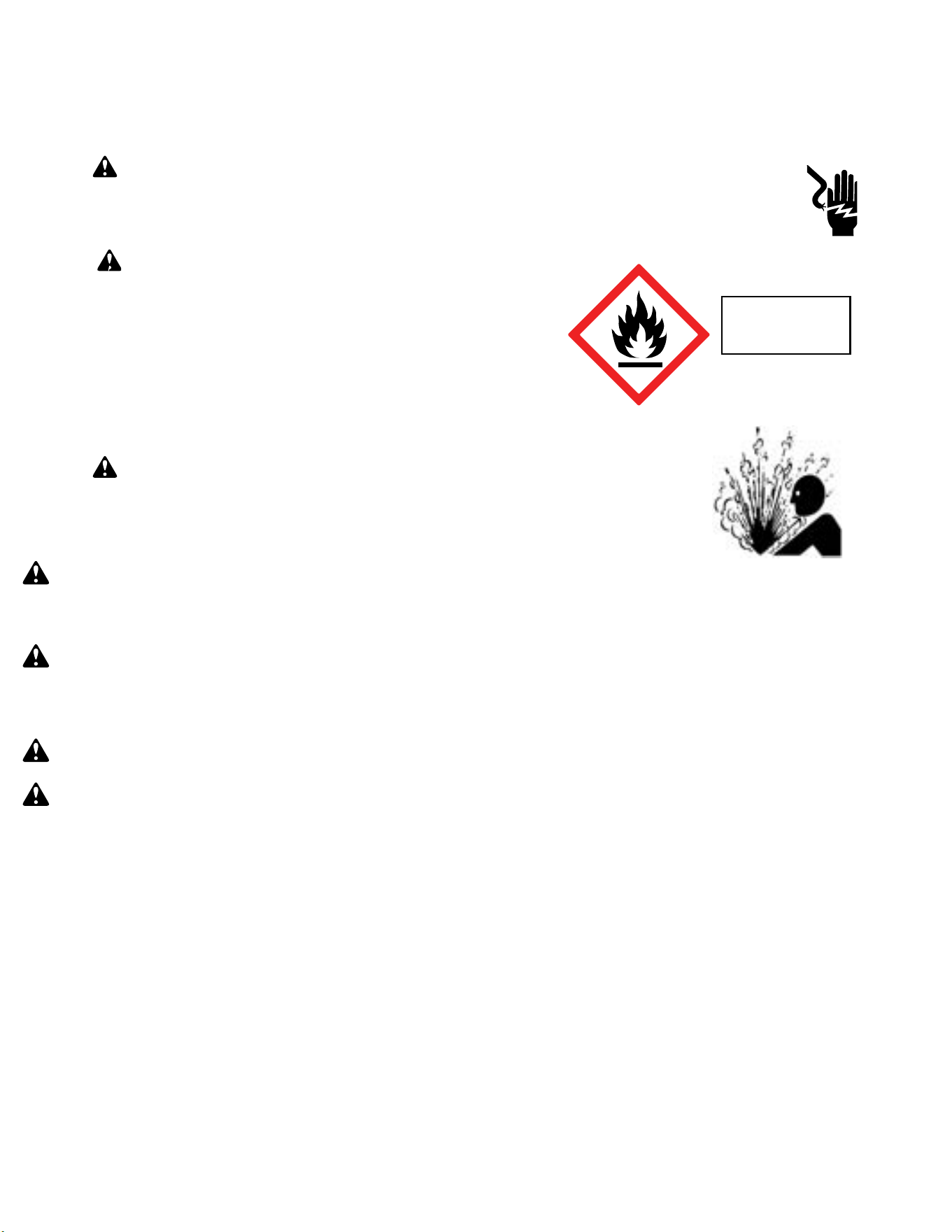
77 77
Warning: Prior to beginning work on systems containing FLAMMABLE REFRIGERANTS, safety checks are necessary to ensure that the risk of ignition
is minimized.
NOTICE: Individuals working on these units must be EPA 608 Certified along with A2L Refrigerant Training.
Warning: Refrigerant 32 cannot be used as a retrofit for R-410A refrigerant. The mixing of refrigerant across classes is prohibited. R-32 Is not a drop
in replacement for R-410A.
General Work Area: All maintenance staff and others working in the installation area shall be instructed on the nature of work being carried out. Work in confined
spaces as defined by the Occupational Safety And Health Administration shall be avoided.
Warning: Job site should be examined for safety hazards such as flammable vapors, ignition sources, ventilation and confined spaces. Create a safe
perimeter with barriers and signs designating a flammable area.
Warning: Work shall be undertaken under a controlled procedure so as to minimise the risk of a flammable gas or vapor being present while the work
is being performed.
Check for presence of refrigerant:
• The area shall be checked with an appropriate refrigerant detector prior to and during work, to ensure the technician is aware of potentially toxic or
flammable atmospheres.
• Ensure that the leak detection equipment being used is suitable for use with all applicable refrigerants, i.e. non-sparking, adequately sealed or intrinsically
safe.
• Under no circumstances shall potential sources of ignition be used in the searching for or detection of refrigerant leaks. A halide torch (or any other detector
using a naked flame) shall not be used.
• The following leak detection methods are deemed acceptable for all refrigerant systems:
1. Electronic leak detectors may be used to detect refrigerant leaks but, in the case of FLAMMABLE REFRIGERANTS, the sensitivity may not be adequate,
or may need re-calibration. (Detection equipment shall be calibrated in a refrigerant-free area.) Ensure that the detector is not a potential source of
ignition and is suitable for the refrigerant used. 2. Leak detection fluids are also suitable for use with most refrigerants but the use of detergents
containing chlorine shall be avoided as the chlorine may react with the refrigerant and corrode the copper pipe-work.
If a leak is suspected, all flame sources shall be removed/extinguished.
If a leakage of refrigerant is found which requires brazing, all of the refrigerant shall be recovered from the system per EPA guidelines.
Presence of fire extinguisher: If any hot work is to be conducted on the refrigerating equipment or any associated parts, a class ABC Rated fire extinguishing
equipment shall be available to hand. Have a class ABC Rated fire extinguisher adjacent to the charging area.
WARNING: Electrical Shock Hazard
Disconnect all power to the unit before starting maintenance. All electrical connections and wiring MUST be installed by a qualified
electrician and conform to all codes which have jurisdiction. Failure to do so can result in property damage, severe electrical
shock or death.
WARNING: This Product uses R-32 Refrigerant
Do not use means to accelerate the defrosting process or to clean, other than those
recommended by the manufacturer.
When not installed, the appliance shall be stored in a room without continuously
operating ignition sources (for example: open flames, an operating gas appliance or
an operating electric heater.
Do not pierce or burn.
Be aware that refrigerants may not contain an odor.
WARNING:
Refrigeration System under High pressure
Do not puncture, heat, expose to flame or incinerate. Only certified refrigeration technicians should service this
equipment. R-32 systems operate at higher pressures than R22 equipment. Appropriate safe service and
handling practices must be used.
Refrigerant
Safety Group
A2L
R-32 SEALED SYSTEM REPAIR
General Information

78 78
Warning:
No ignition sources: No person carrying out work in relation to a REFRIGERATING SYSTEM which involves exposing any pipe work shall use any sources of
ignition in such a manner that it may lead to the risk of fire or explosion. All possible ignition sources, including cigarette smoking, should be kept sufficiently far
away from the site of installation, repairing, removing and disposal, during which refrigerant can possibly be released to the surrounding space. Prior to work
taking place, the area around the equipment is to be surveyed to make sure that there are no flammable hazards or ignition risks.
Ventilated Area: Ensure that the area is in the open or that it is adequately ventilated before accessing the refrigerant in the system or conducting any hot work.
A degree of ventilation shall continue during the period that the work is carried out. The ventilation should safely disperse any released refrigerant away from
the work area or external to building envelope.
During Repairs To Sealed Components: All power must be removed from the equipment being worked on prior to any removal of sealed covers, etc. If it is
absolutely necessary to have an electrical supply to equipment during servicing, then a constant leak detector shall be located at the most critical point to warn
of a potentially hazardous situation.
Checks And Repairs To Electrical Devices:
• Repair and maintenance to electrical components shall include initial safety checks and component inspection procedures. If a fault exists that could
compromise safety, then no electrical supply shall be connected to the circuit until it is satisfactorily dealt with. If the fault cannot be corrected remove
power supply to unit. DO NOT OPERATE.
• Initial safety checks shall include:
•That capacitors are discharged: this shall be done in a safe manner to avoid possibility of sparking;
•That no live electrical components and wiring are exposed while charging, recovering or purging the system;
•Verify unit is properly grounded.
• Particular attention shall be paid to the following to ensure that by working on electrical components, the casing is not altered in such a way that the level of
protection is affected. This shall include damage to cables, excessive number of connections, terminals not made to original specification, damage to seals,
incorrect fitting of glands, etc.
• Ensure that the apparatus is mounted securely.
• Ensure that seals or sealing materials have not degraded to the point that they no longer serve the purpose of preventing the ingress of flammable
atmospheres. Replacement parts shall be in accordance with the manufacturer’s specifications.
•
The following is a list of important considerations when working with R-32 equipment:
• R-32 pressure is similar to R-410A and approximately 60% higher than R-22 pressure.
• R-32 cylinders must not be allowed to exceed 125˚F, they may leak or rupture.
• R-32 must never be pressurized with a mixture of compressed air, it may become MORE flammable.
• Servicing equipment and components must be specifically designed for use with R-32 and dedicated to prevent contamination.
• Manifold sets must be equipped with gauges capable of reading 750 psig (high side) and 200 psig (low side), with a 500-psig low-side retard.
• Gauge hoses must have a minimum 750-psig service pressure rating.
• Recovery cylinders must have a minimum service pressure rating of 400 psig, (DOT 4BA400 and DOT BW400 approved cylinders).
• POE (Polyol-Ester) lubricants must be used with R-32 equipment.
• To prevent moisture absorption and lubricant contamination, do not leave the refrigeration system open to the atmosphere for extended periods of time.
• If unit refrigerant is low, recover the refrigerant, evacuate, and recharge unit to nameplate amount.
• If there is any amount of refrigerant in the system charge from the low side.
• Always charge by liquid inverted.
NOTE: Sealed system repairs to cool-only models require the installation of a liquid line drier.
NOTE: Sealed system repairs to models with a heat pump require the installation of a suction side drier.
Verify with tool manufacturers that all tools used during this repair are non-sparking and can be used with A2L Refrigerants.
No halide torches for leak testing.
Refrigerant monitors or detectors must be used to detect refrigerant in the work area.
• R-32 A2L Refrigerant Recovery System.
• Vacuum Pump rated for A2L refrigerant (capable of 300 microns or less vacuum.)
• Nitrogen bottle with purging and pressurizing capabilities up to 550 psi.
• Oxy/ Acetylene torch or similar equipment utilized for brazing.
• Non-Sparking (Not Halide)Electronic Leak Detector rated for detecting A2L refrigerant.
• Digital refrigerant scale
• Refrigeration Gauges rated for A2L Refrigerants with temp scales for R-32 refrigerant.
• Gauge Manifold (Right handed threads).
• A2L compatible Vacuum Gauge capable of 300 microns or less.
• Nitrogen regulator for purging and testing, rated to 800 psi. (Capable of low psi flow)
• Pipe tubing cutter.
• Refrigerant recovery cylinder. (Flammable A2L label)
R-32 SEALED SYSTEM REPAIR
General Information
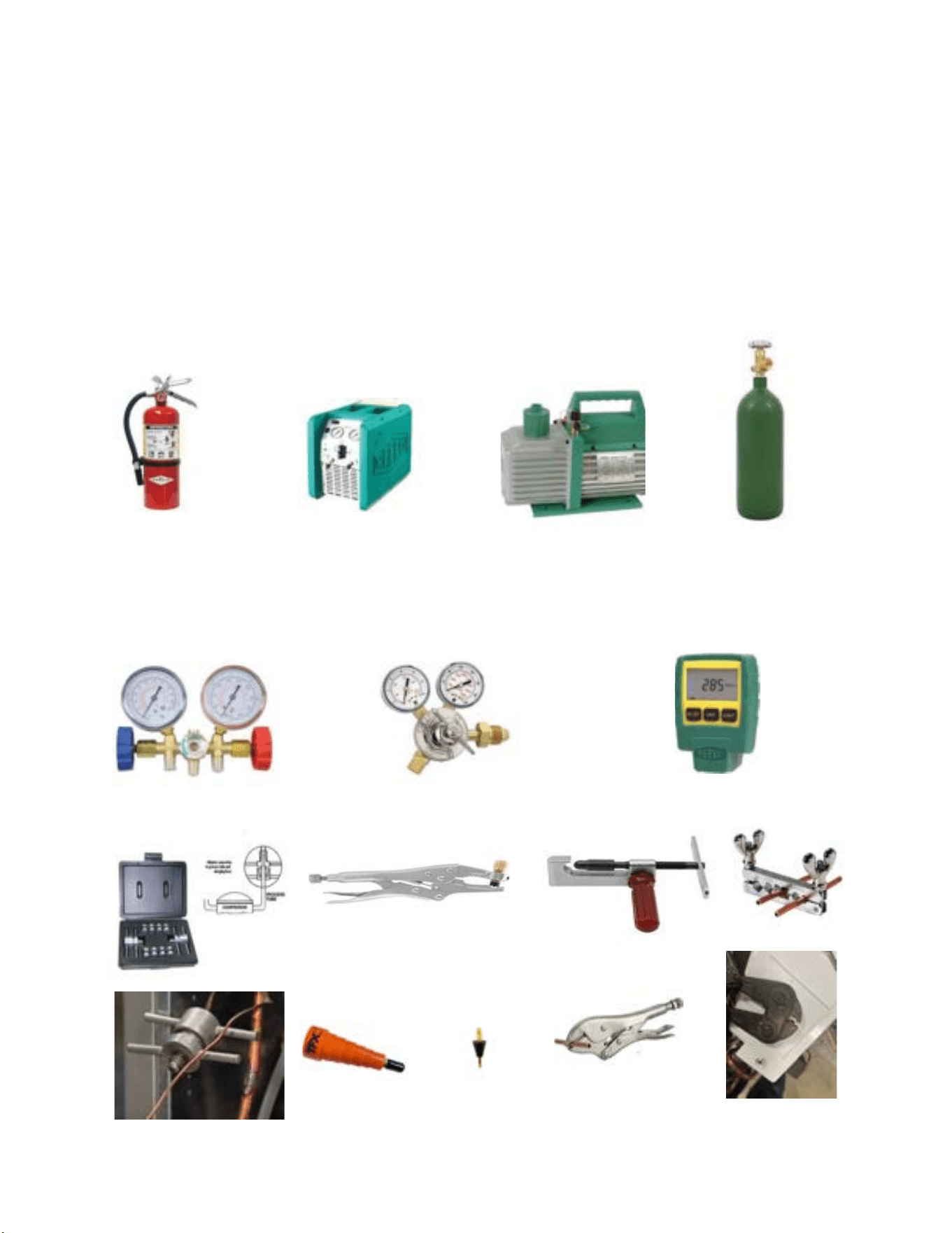
79 79
• Ventilation fan.
• Class ABC fire extinguisher.
• Process Tube adapter kit
• Recovery access tool.
• Purge hose fittings
• Pinch off and opening tools
R-32 SEALED SYSTEM REPAIR
Required Equipment
27
Process tube adapter kit
Pinch off and opening tools
Recovery access tool
Purge hose fittings
Recovery Machine
Vaccum Pump
Nitrogen
ABC Fire Extinguisher
Guage Manifold
Nitrogen Regulator
Vaccum Guage

80 80
R-32 SEALED SYSTEM REPAIR
Refrigerant Removal, Recovery, and Evacuation
NOTE: When accessing the refrigerant in the system to make repairs or for any other purpose, conventional procedures shall be used. However, for FLAMMABLE
REFRIGERANTS (R-32 is classified in the A2L group for mildly flammable refrigerants) it is important that best practice is followed since flammability is a
consideration. Follow all EPA 608 regulations and procedures along with AHRI 15 Best Practices for A2L refrigerants.
Warning: Ensure sufficient ventilation at the repair place.
Warning: Ensure there are no open flame sources or hot surfaces that exceed 1200˚F in the work area.
Warning: Discharge capacitors in a way that won’t cause any spark. The standard procedure to short circuit the capacitor terminals usually creates
sparks.
NOTICE: Ensure that the following precautions are taken prior to opening the sealed system.
• Verify Recovery machine is rated for A2L refrigerants.
• Mark the Job site inspection area as flammable work zone using appropriate signs.
• Utilize a Refrigerant leak detector or refrigerant monitor to sense the area for the presence of refrigerants.
• Disconnect all power supply to unit.
• Properly ground all equipment and hoses along with tank to prevent a static build up .
• Ensure adequate ventilation is provided for the job site.
• Do not mix A2L refrigerant Gages and hoses with other refrigerants.
• Keep exposure of refrigerant to Air to as minimum as possible (creates a dangerous condition).
• Under no circumstances is the mixing of refrigerants in the recovery cylinders allowed and should be strictly avoided at all times. Do not introduce
oxygen into any recovery cylinders.
1. Install a piercing valve to recover refrigerant from the sealed system. (Piercing valve must be removed from the system before recharging.)
2. Recover refrigerant to EPA sec. 608 standards. If a low charge is suspected weigh recovered refrigerant and compare to unit nameplate.
NOTE: DO NOT RECOVER TO A VACUUM PRIOR TO FLUSHING WITH NITROGEN. STOP RECOVERY AT 0-5 PSI.
3. Flush refrigerant out of system with a dry nitrogen purge, make sure you energize and de-energize all reversing valves and solenoid valves to release any
trapped refrigerant.(3-5minutes).
4. Perform an evacuation to 29.9 in. hg. and break vacuum with Dry Nitrogen.
5. Re-purge the unit for 3-5 mins or until the nitrogen flows out both process tubes.
6. Re-evacuate unit to 29.9 in. hg. and break vacuum with Dry Nitrogen.
8. Open the refrigerant circuit by cutting out components.
9. Cut off the crimp on the process tubes and install a 5/16 copper access fitting to the process tube.
Transportation
Be aware that local, state, and national codes exist that regulate the transportation of flammable gases. Be sure to become informed of the regulations and always stay compliant.
81 81
R-32 SEALED SYSTEM REPAIR
Component Replacement/Brazing
• Warning: Ensure sufficient ventilation at the repair place.
Warning: Presence of fire extinguisher. If any hot work is to be conducted on the refrigerating equipment or any associated parts, have a ABC class fire
extinguisher available to hand.
Warning: No person carrying out work in relation to a REFRIGERATING SYSTEM which involves exposing any pipe work shall use any sources of ignition in such a
manner that it may lead to the risk of fire or explosion. All possible ignition sources, including cigarette smoking, should be kept sufficiently far away from the site of installation,
repairing, removing and disposal, during which refrigerant can possibly be released to the surrounding space. Prior to work taking place, the area around the equipment
is to be surveyed to make sure that there are no flammable hazards or ignition risks.
Warning: Ensure there are no open flame sources or hot surfaces that exceed 1200˚F in the work area.
NOTE: When brazing is required, the following procedures shall be carried out in the right order:
1. Remove and recover refrigerant, and evacuate the system. Refer to the refrigerant removal, recovery, and evacuation section of this manual.
Warning: Under no circumstances shall potential sources of ignition be used in the searching for or detection of refrigerant leaks. A halide torch (or any other detector
using a naked flame) shall not be used.
2. Perform a check of the work area for the presence of flammable refrigerant prior to brazing or performing any hot work. Use a non-Sparking (Not Halide )
A2L certified Electronic Leak Detector rated for detecting R-32 refrigerant.
3. Re-pipe all repairs and install all components to sealed system.
NOTE: Sealed system repairs require the installation of a liquid line drier upstream of the condenser.
NOTE: Sealed system repairs to models with a heat pump require the installation liquid line drier on the cooling liquid line.
Refer to Figure 701 for installation location of liquid line drier on unit with heat pump.
4. Purge nitrogen through the unit. at approximately 2-3 psi through the duration of the brazing process. (Nitrogen must be purging through the unit while any
brazing is being performed.)
5. Pressure test unit to 550 psi minimum and hold pressure for 30 minutes minimum. Inspect for any leaks with a leak detection fluid and repair as required.
Repeat as required until system passes leak test.
6. Triple evacuate the unit to achieve a 500 micron level.
7. Pressurize nitrogen to 550 psi and leak test all connections with a leak detection fluid. Repair any leaks found.
8. Reassemble sealed enclosures accurately. If seals are worn, replace them.
9. Charge the system with the amount of refrigerant specified on the model nameplate.
Refer to the refrigerant charging section of this manual for charging
procedures.
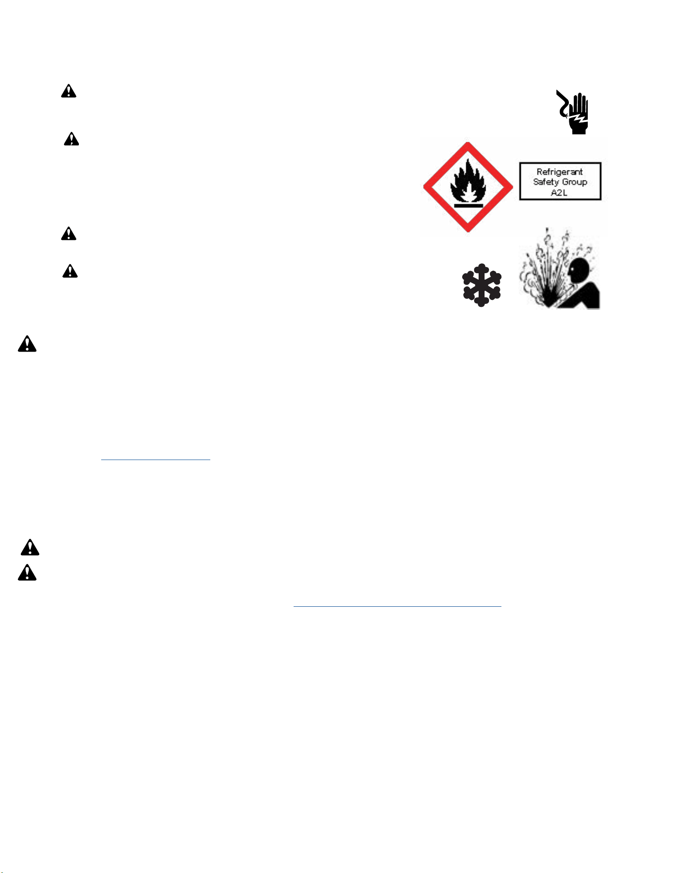
82 82
R-32 SEALED SYSTEM REPAIRS
Refrigerant Charging
NOTE: Always weigh in refrigerant based on the model nameplate.
Warning:
• Ensure that contamination of different refrigerants does not occur when using charging equipment.
• Hoses or lines shall be as short as possible to minimise the amount of refrigerant contained in them.
• Charge unit with refrigerant cylinder in the inverted position to obtain liquid refrigerant.
• Charge the unit according to the amount on the name plate matching the unit.
• Extreme care shall be taken not to overfill the REFRIGERATING SYSTEM.
• Prior to recharging a system, it shall be pressure-tested with the dry nitrogen.
NOTE: Because the refrigerant system is a sealed system, service process tubes will have to be installed. First install a line tap and recover refrigerant from
system. Refer to the Refrigerant removal section of this manual for procedures.
The acceptable method for charging the sealed system is the Weighed in Charge Method. The weighed in charge method is applicable to all units. It is the
preferred method to use, as it is the most accurate.
The weighed in method should always be used whenever a charge is removed from a unit such as for a leak repair, compressor replacement, or when there is
no refrigerant charge left in the unit. To charge by this method, requires the following steps:
•
Warning: Ensure sufficient ventilation at the repair place.
Warning: Ensure there are no open flame sources or hot surfaces that exceed 1200˚F in the work area.
1. Recover Refrigerant in accordance with EPA regulations. (Refer to
Refrigerant Removal, Recovery, and Evacuation Section).
NOTE: If a low charge is suspected weigh recovered refrigerant and compare to unit nameplate.
NOTE: Access valves must be removed after charging is complete to return this unit to a sealed system.
2. Weigh in the refrigerant charge with the proper quantity of R-32 refrigerant per model nameplate.
3. Crimp the process tube and solder the end shut.
4. Start unit, and verify performance.
NOTE: EPA Section 608 regulations require that if a system is charged with flammable refrigerant it must have red markings on the access ports (Process
tube).
WARNING: Electrical Shock Hazard
Disconnect all power to the unit before starting maintenance. All electrical connections and wiring MUST be installed by a qualified electrician
and conform to all codes which have jurisdiction. Failure to do so can result in property damage, severe electrical shock or death.
WARNING: This Product uses R-32 Refrigerant
Do not use means to accelerate the defrosting process or to clean, other than those recommended by the
manufacturer.
When not installed, the appliance shall be stored in a room without continuously operating ignition
sources (for example: open flames, an operating gas appliance or an operating electric heater.
Do not pierce or burn.
Be aware that refrigerants may not contain an odor.
WARNING:
Refrigeration System under High pressure
Do not puncture, heat, expose to flame or incinerate. Only certified refrigeration technicians should service this equipment. R32 systems
operate at higher pressures than R22 equipment. Appropriate safe service and handling practices must be used.
WARNING:
Freeze Hazard
Proper safety procedures must be followed, and all PPE must be utilized when working with liquid refrigerant. Failure to
comply could result in minor to moderate injury.
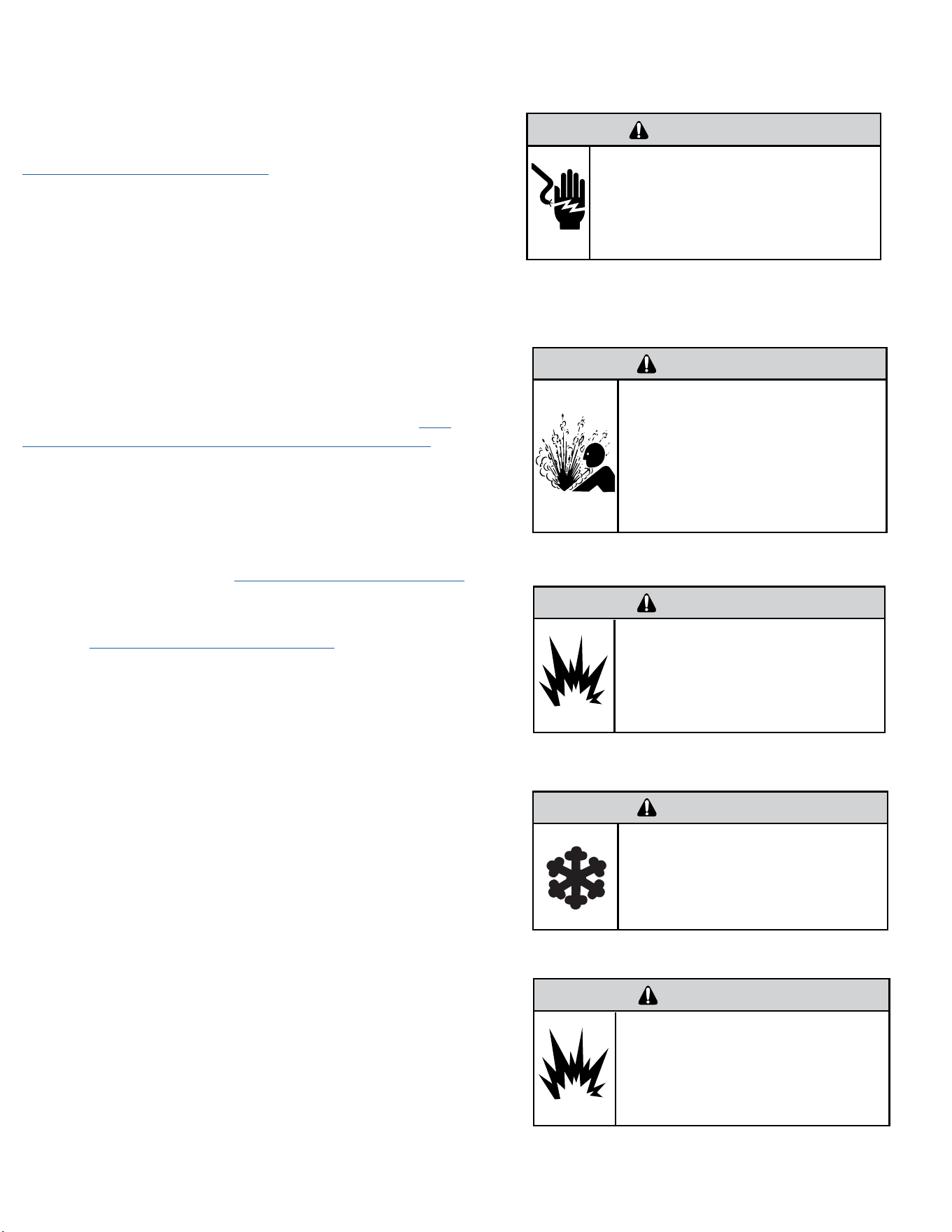
83 83
R-32 SEALED SYSTEM REPAIRS
Compressor Replacement
WARNING
ELECTRIC SHOCK HAZARD
Turn off electric power before service or
installation. Extreme care must be used, if it
becomes necessary to work on equipment with
power applied.
Failure to do so could result in serious injury or
death.
1. Be certain to perform all necessary electrical and refrigeration tests to be
sure the compressor is actually defective before replacing.
2. Recover all refrigerant from the system though the process tubes. Refer to
Refrigerant Removal, Recovery, and Evacuation Section of this manual).
PROPER HANDLING OF RECOVERED REFRIGERANT ACCORDING TO EPA
REGULATIONS IS REQUIRED.
3. After all refrigerant has been recovered, cut and remove compressor.
Be certain to have both suction and discharge process tubes open to
atmosphere.
4. Carefully pour a small amount of oil from the suction stub of the defective
compressor into a clean container.
5. Using an acid test kit (one shot or conventional kit), test the oil for acid
content according to the instructions with the kit.
6. If any evidence of a burnout is found, no matter how slight, refer to
Com-
pressor Replacement -Special Procedure in Case of Compressor Burnout.
7. Install the replacement compressor.
CAUTION: Seal all openings on the defective compressor immediately.
Compressor manufacturers will void warranties on units received not
properly sealed. Do not distort the manufacturers tube connections.
8. Braze all connections. Refer to the Component Replacement/Brazing section
of this manual.
9. Charge system with proper amount of refrigerant per the model nameplate.
Refer to the Refrigerant charging section of this manual.
WARNING
EXPLOSION HAZARD
The use of nitrogen requires a pressure
regulator. Follow all safety procedures and
wear protective safety clothing etc.
Failure to follow proper safety procedures
could result in serious injury or death.
FREEZE HAZARD
Proper safety procedures must be followed,
and proper protective clothing must be worn
when working with liquid refrigerant.
Failure to follow these procedures could
result in minor to moderate injury.
CAUTION
WARNING
NEVER, under any circumstances,
liquid charge a rotary-compressor
through the LOW side. Doing so
would cause permanent damage to
the new compressor. Use a charging
adapter.
WARNING
HIGH PRESSURE HAZARD
Sealed Refrigeration System contains refrigerant
and oil under high pressure.
Proper safety procedures must be followed,
and PPE must be utilized
when working with refrigerants.
Failure to follow these procedures could
result in serious injury or death.
84 84
R-32 SEALED SYSTEM REPAIRS
Compressor Replacement -Special Procedure in Case of Compressor Burnout
WARNING
HIGH PRESSURE HAZARD
Sealed Refrigeration System contains refrigerant
and oil under high pressure.
Proper safety procedures must be followed,
and PPE must be utilized
when working with refrigerants.
Failure to follow these procedures could
result in serious injury or death.
WARNING
ELECTRIC SHOCK HAZARD
Turn off electric power before service or
installation. Extreme care must be used, if it
becomes necessary to work on equipment with
power applied.
Failure to do so could result in serious injury or
death.
WARNING
EXPLOSION HAZARD
The use of nitrogen requires a pressure
regulator. Follow all safety procedures and
wear protective safety clothing etc.
Failure to follow proper safety procedures
could result in serious injury or death.
1. Recover all refrigerant and oil from the system. Refer to Refrigerant Removal,
Recovery, and Evacuation Section
of this manual.
2. Cut and remove compressor and fixed orifice from the system.
CAUTION: Seal all openings on the defective compressor immediately.
Compressor manufacturers will void warranties on units received not
properly sealed. Do not distort the manufacturers tube connections.
3. Flush evaporator condenser and all connecting tubing with dry nitrogen
or equivalent. Use A2L approved flushing agent to remove all contamination
from system. Inspect suction and discharge line for carbon deposits. Remove
and clean if necessary. Ensure all acid is neutralized.
4. Reassemble the system, including a new metering device and strainers.
5. Install a dual port suction line drier on the common suction line and
remove when the pressure differential across the drier ports reaches 3 psi. or
greater.
6. Braze all connections. Refer to the Brazing section of this manual.
7. Charge system with proper amount of refrigerant per the model nameplate.
Refer to the refrigerant charging section of this manual.
WARNING
NEVER, under any circumstances,
liquid charge a rotary-compressor
through the LOW side. Doing so
would cause permanent damage to
the new compressor. Use a charging
adapter.
85 85
R-32 SEALED SYSTEM REPAIR
Replace The Reversing Valve
WARNING
HIGH PRESSURE HAZARD
Sealed Refrigeration System contains refrigerant
and oil under high pressure.
Proper safety procedures must be followed,
and PPE must be utilized
when working with refrigerants.
Failure to follow these procedures could
result in serious injury or death.
NOTICE
FIRE HAZARD
The use of a torch requires extreme care and proper
judgment. Follow all safety recommended precautions and
notice could result in moderate to serious property damage.
1. Recover all refrigerant from the system though the process tubes. Refer to Refrigerant Removal, Recovery, and Evacuation Section of this manual).
PROPER HANDLING OF RECOVERED REFRIGERANT ACCORDING TO EPA REGULATIONS IS REQUIRED.
2. Remove solenoid coil from reversing valve. If coil is to be reused, protect from heat while changing valve.
NOTE: When brazing a reversing valve into the system, it is of extreme importance that the temperature of the valve does not exceed 250°F at any time.
Wrap the reversing valve with a large rag saturated with water. “Re-wet” the rag and thoroughly cool the valve after each brazing operation of the four joints
involved.
The wet rag around the reversing valve will eliminate conduction of heat to the valve body when brazing the line connection.
3. Cut all lines from reversing valve. Refer to the Brazing section of this manual.
4. Clean all excess braze from all tubing so that they will slip into fittings on new valve.
5. Remove solenoid coil from new valve.
6. Protect new valve body from heat while brazing with plastic heat sink (Thermo Trap) or wrap valve body with wet rag.
7. Fit all lines into new valve and braze lines into new valve.
8. Braze all connections. Refer to the Brazing section of this manual.
9. Pressurize with nitrogen to 550 psi and leak test all connections with a leak detection fluid. Repair any leaks found.
10. Once the sealed system is leak free, install solenoid coil on new valve.
11. Charge system with proper amount of refrigerant per the model nameplate. Refer to the refrigerant charging section of this manual.
WARNING
EXPLOSION HAZARD
The use of nitrogen requires a pressure
regulator. Follow all safety procedures and
wear protective safety clothing etc.
Failure to follow proper safety procedures
could result in serious injury or death.
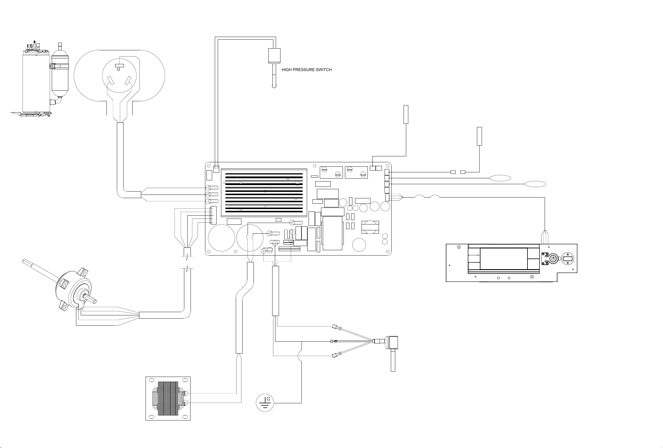
WIRING DIAGRAMS
Figure 901
U
W
V
BLU
YEL
RED
U
W
V
BLU
YEL
WHT
BLK
RED
BLU
YEL
WHT
BLK
RED
WHT
BLK
GREEN
L2/N
L1/L
BLK
LCDI
UI
BLU
RE-400
RE-401
RV2
L2/N
GND
L1/L
DISCH TEMP SENSOR
AMB TEMP SENSOR
ID COIL
TEMP SENSOR
OD COIL
TEMP SENSOR
BLK
INDUCTOR / REACTOR
GND
HIGH PRESSURE SWITCH
KCVS08B10A
KCVS12B10A
KCVM14B10A
KCVS12B30A
KCVS16B30A
WCVT12B10A
WCVT10B10A
WCVT10B30A
WCVT12B30A
WCVT16B30A
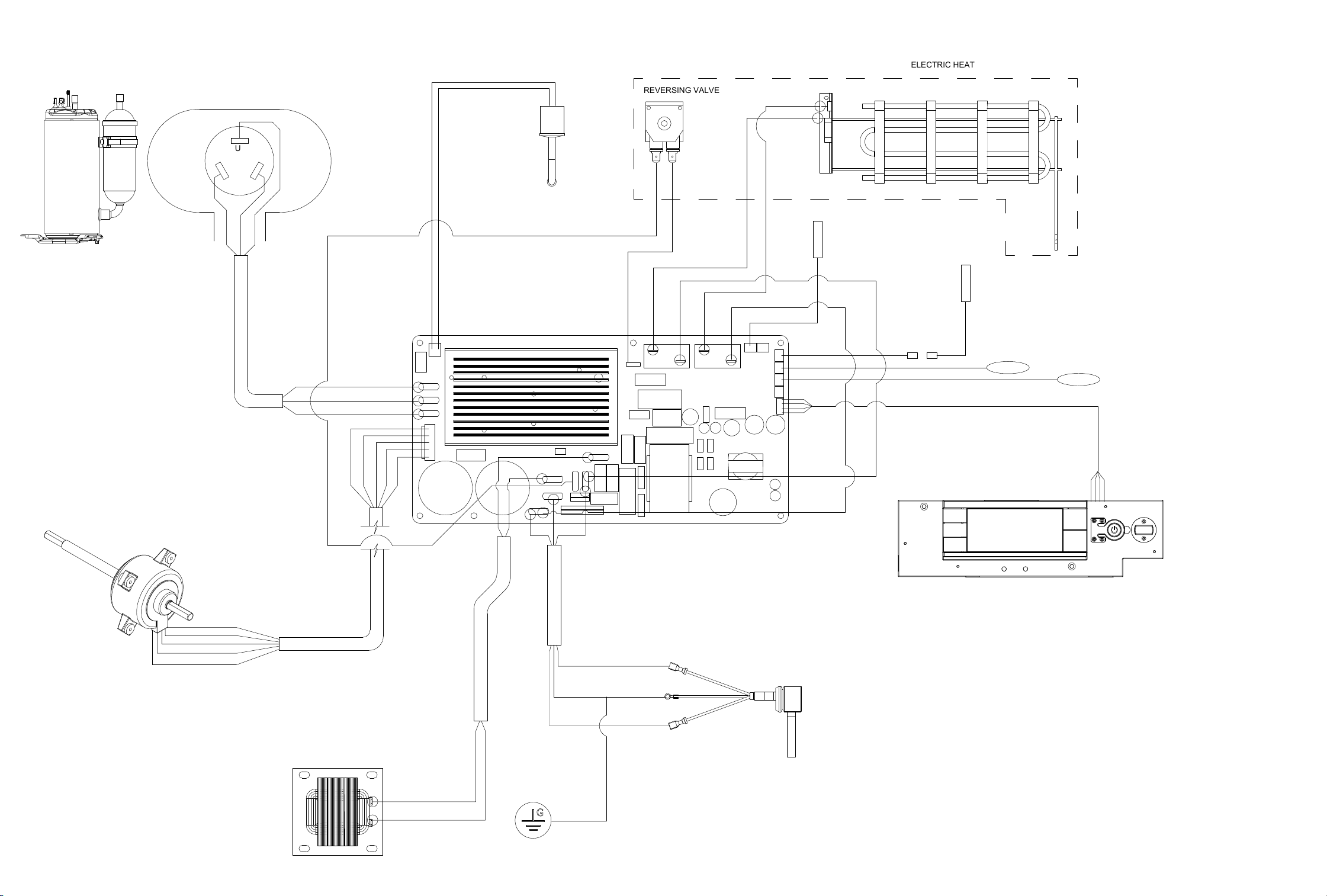
WIRING DIAGRAMS
Figure 902
KHVS10B11A
KHVS12B33A
WHVT14B33A
KHVQ10B11A
U
W
V
EH2
RELAY
EHL2
BLU
YEL
RED
U
W
V
BLU
YEL
WHT
BLK
RED
BLU
YEL
WHT
BLK
RED
WHT
BLK
GREEN
L2/N
L1/L
RE-400
RE-401
BLK
LCDI
UI
RV1
EHL1
EH1
RELAY
RV1
RELAY
BLU
BLU
BLU
BLU
RV2
RED
RED
ORG
ORG
RE-400
RE-401
RV2
L2/N
GND
L1/L
RED
ORG
DISCH TEMP SENSOR
AMB TEMP SENSOR
ID COIL
TEMP SENSOR
OD COIL
TEMP SENSOR
BLK
INDUCTOR / REACTOR
HPS
GND
ELECTRIC HEAT
REVERSING VALVE
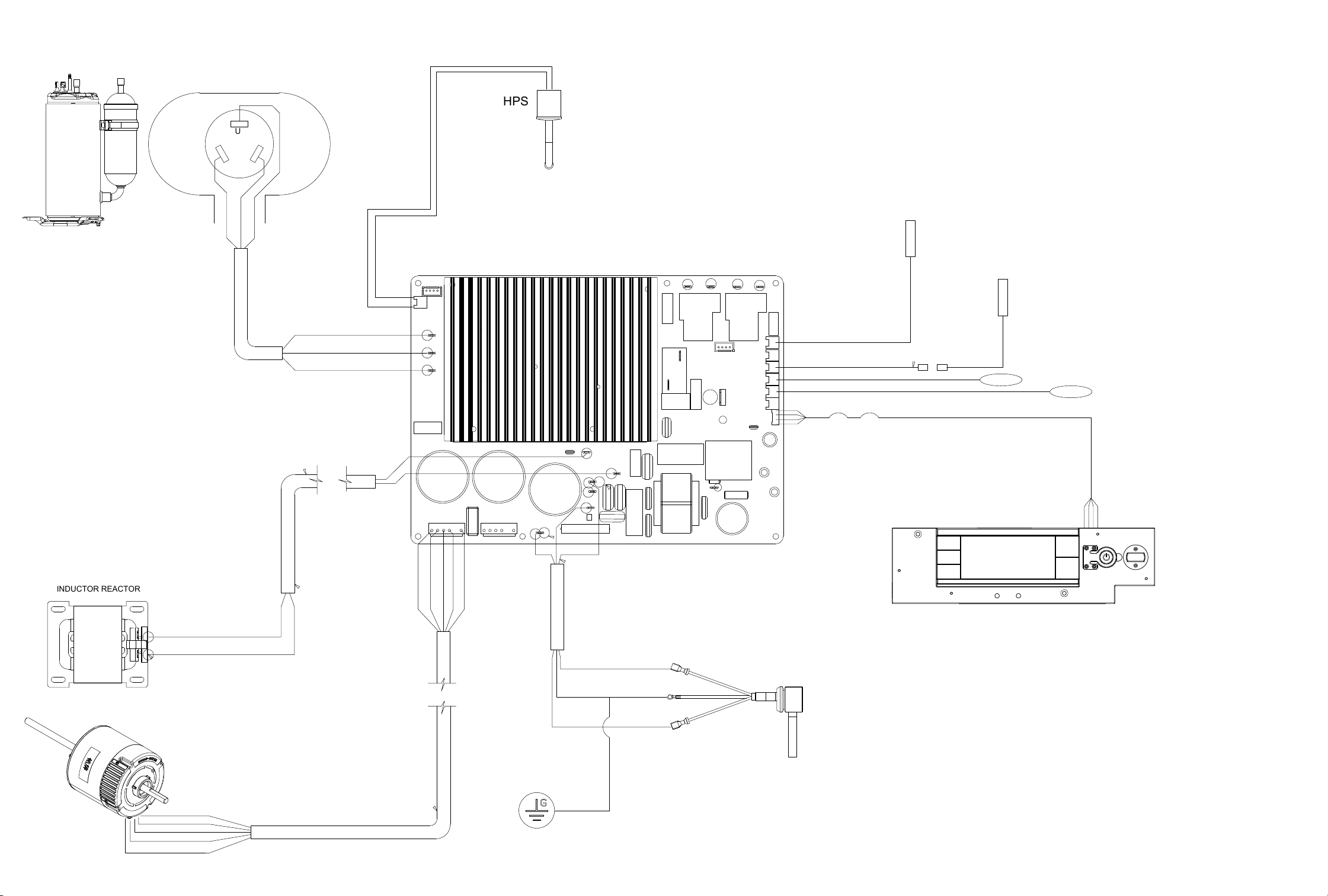
WIRING DIAGRAMS
Figure 903
U
W
V
EH2
RELAY
BLU
YEL
RED
U
W
V
BLU
YEL
WHT
BLK
RED
BLU
YEL
WHT
BLK
RED
WHT
BLK
GREEN
GROUND
L2/N
GND
L1/L
BLK
BLK
POWER SUPPLY
230/208 VAC
LCDI
UI
EH1
RELAY
RV1
RELAY
RE-400
RE-401
L2/N
GND
L1/L
DISCH TEMP SENSOR
AMB TEMP SENSOR
ID COIL
TEMP SENSOR
OD COIL
TEMP SENSOR
RV1
HPS
INDUCTOR REACTOR
KCVM18B30A
KCVM24B30A
KCVL28B30A
KCVL36B30A
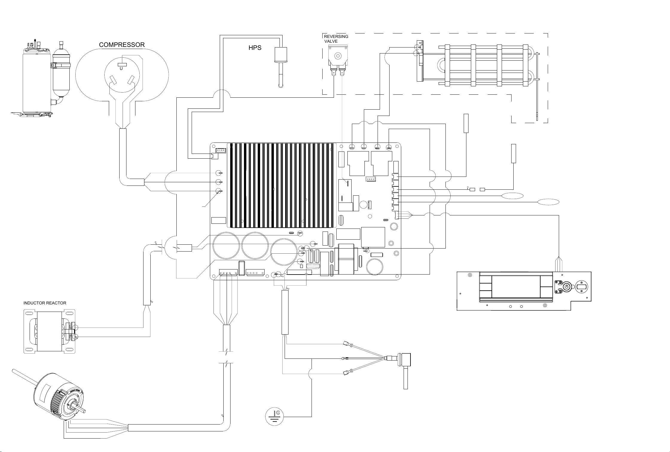
WIRING DIAGRAMS
Figure 904
KHVM24B34A
KHVL28B35A
U
W
V
EH2
RELAY
EHL2
BLU
YEL
RED
U
W
V
BLU
YEL
WHT
BLK
RED
BLU
YEL
WHT
BLK
RED
WHT
BLK
GREEN
GROUND
L2/N
GND
L1/L
BLK
BLK
POWER SUPPLY
230/208 VAC
LCDI
UI
RV1
EHL1
EH1
RELAY
RV1
RELAY
BLU
BLU
BLU
BLU
RV2
RED
RED
ORG
ORG
RE-400
RE-401
RV2
L2/N
GND
L1/L
RED
ORG
ELECTRICAL HEATER
DISCH TEMP SENSOR
AMB TEMP SENSOR
ID COIL
TEMP SENSOR
OD COIL
TEMP SENSOR
RV2
RV1
RED
ORG
HPS
COMPRESSOR
REVERSING
VALVE
INDUCTOR REACTOR
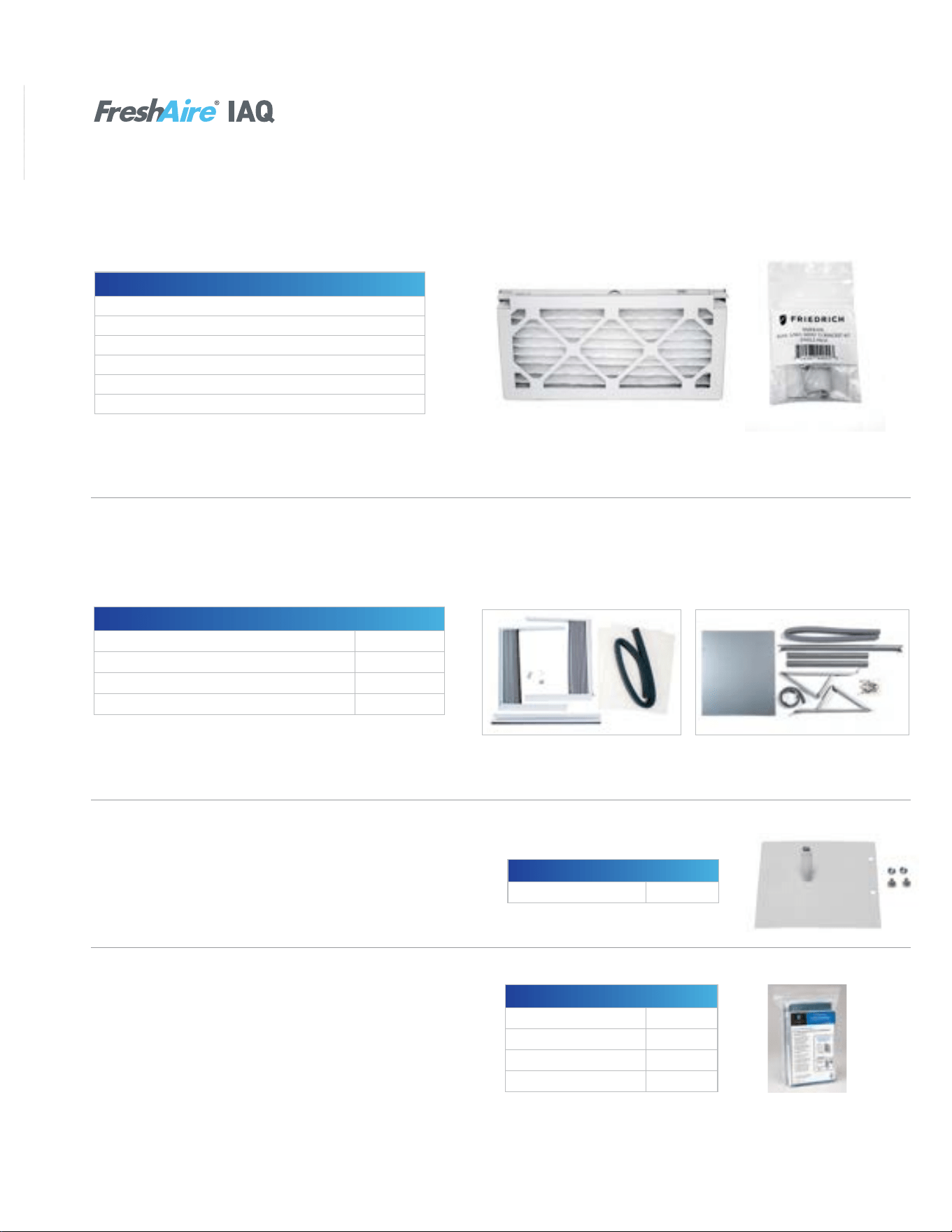
90 90
APPENDIX
Available Accessories-Kuhl
7
MERV 13 Filters/Filter Brackets
Kühl
®
air conditioners can utilize an optional FreshAire
®
MERV 13 air filter that’s effective at capturing and removing
microorganisms from the air, which according to ASHRAE
1
, the leading authority on the science behind advanced indoor
air quality, include harmful airborne viruses.
1
Based on ASHRAE Guidance for Building Operations during the COVID-19 Pandemic.
Model No. UPC Description
KMFB1PK 724587440553 Kühl MERV filter bracket 1 pack
KMFBQ1PK 724587440546 Kühl Q MERV filter bracket 1 pack
KMFQ3PK 724587440560 Kühl MERV filter – Q chassis 3 pack
KMFS3PK 724587440577 Kühl MERV filter – S chassis 3 pack
KMFM3PK 724587440584 Kühl MERV filter – M chassis 3 pack
KMFL3PK 724587440591 Kühl MERV filter – L chassis 3 pack
NOTE: Filter bracket required for MERV 13 filter installation; Minimum
bracket order of 24; Minimum filter order quantity of eight.
Window Mounting Kits
2
: Kühl
®
+
Window kits are included with cooling only models, but are an accessory item for Kühl
®
+ heat/cool models.
2
Window kits are required for installation of Kühl
®
+ models in a window.
3
Does not include window brackets.
KWIKQA KWIKSB, KWIKMB, KWIKLB
Heat / Cool Models Kit No.
KHVQ10B11A
3
KWIKQA
KHS10B10A, KHVS10B11A, KHVS12B33A, KEVS16B33A KWIKSB
KHVM24B34A KWIKMB
KHVL28B35A, KEVL36B35A KWIKLB
Premium Carbon Filters
Premium carbon filters remove odors and volatile organic
compounds (VOC) and can achieve up to a MERV 6 rating
when used with a standard filter.
NOTE: Sold as a 3 pack.
Model Kit No.
KCVQ and KHVQ KWCFQ
KCVS, KHVS, and KEVS KWCFS
KCVM and KHVM KWCFM
KCVL, KHVL, and KEL KWCFL
Model Kit No.
All Kühl
®
Series Models DC2
Drain Kit
Drain kits allow the field-installed drain tube to be installed
to the bottom of the sleeve to route the condensate from
the unit.
Kühl
®
Accessories
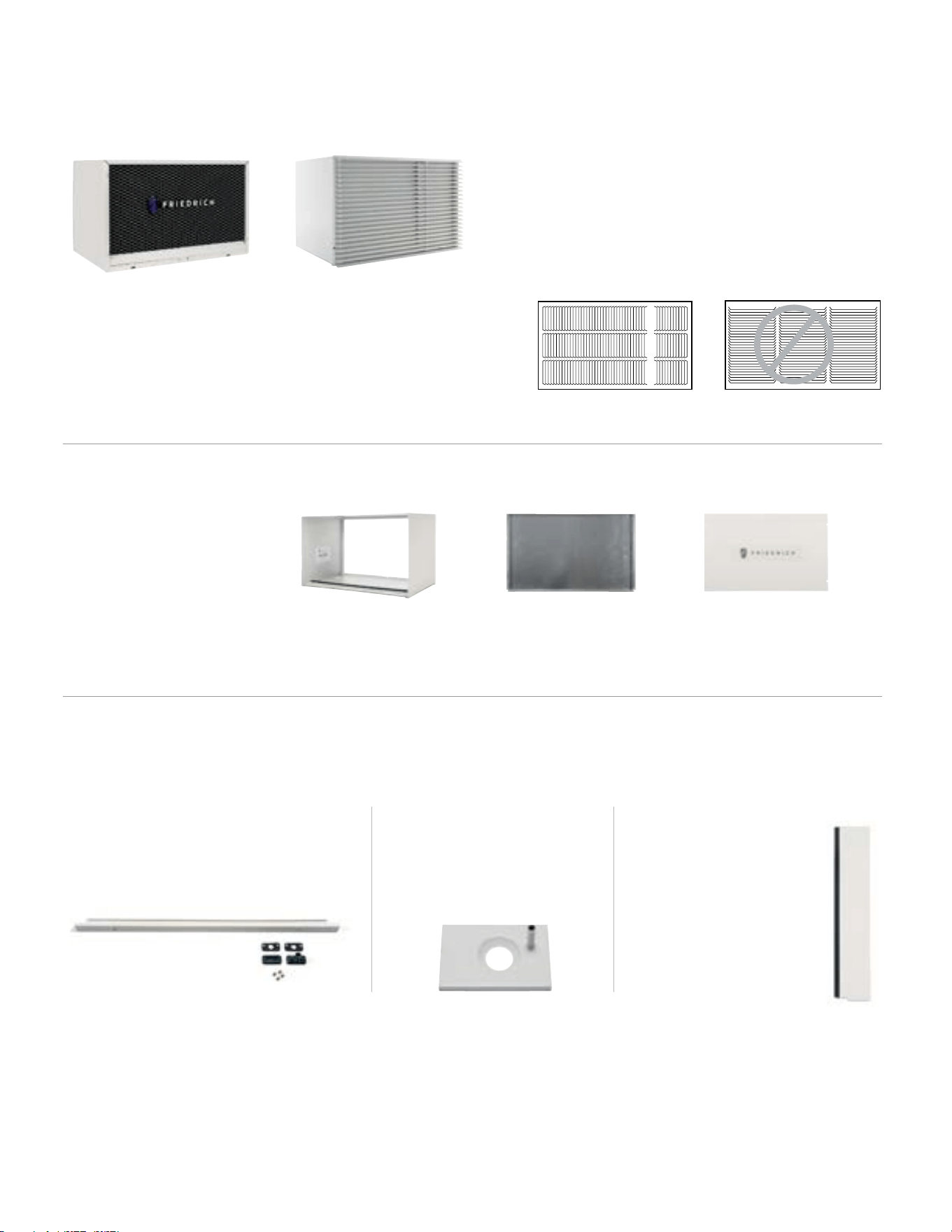
91 91
APPENDIX
Available Accessories-Wallmaster
7
WallMaster
®
Optional Accessories
IMPORTANT:
Operating the air conditioner with incorrect rear grille or without
Baffle Adapter Kit (on 19 ¾" deep sleeve) will recirculate discharge
air and cause compressor overload to trip.
This will cause the unit to shut down temporarily and may lead to
premature compressor failure.
CORRECT: Vertical Louvers
INCORRECT: Horizontal Louvers
WSE Sleeve/Exterior Grilles
Optional Architectural
Grille – AG
Premium extruded
aluminum grille.
Standard Grille
Premium, expanded metal
grille with powder coat paint.
Ships with WSE sleeve.
Installation Accessories
DK (Drain Kit)
Installed at the back of the unit and allows
for attachment to condensate disposal
system, if necessary or desired.
IDK (Internal Drain Kit)
New construction applications
where a condensate drain
system has been built into the
wall interior.
BAK (Baffle Adapter Kit)
Necessary when installing
in a sleeve deeper than
16 ¾" deep, such as Fedders
B sleeve (19 ¾" deep).
WSE Wall Sleeve
Ships with standard grille
(shown above) and standard
galvanized steel inner panel
and painted steel outer panel.
WSE sleeve Steel inner panel Outer weather panel

92 92
APPENDIX
Interactive Parts Viewer
All Friedrich Service Parts can be found on our online interactive parts viewer.
Please click on the link below:
Interactive Parts Viewer
For Further Assistance contact Friedrich customer service at
(1-800-541-6645).
Limited Warranty
Current warranty information can be obtained by referring to https://www.friedrich.com/professional/support/product-resources
93 93
APPENDIX
Thermistor Resistance Values (This Table Applies to All Thermistors)
TEMP RESISTENCE (K Ohms)
RESISTANCE
TOLERANCE %
MAX F MINMIN MAXCENTR
-25 210.889 225.548 240.224 6.50 6.51
178.952
-20
190.889 202.825 6.25 6.25
-15 151.591 161.325 171.059 6.03 6.03
-10 128.434 144.292 5.81136.363 5.81
108.886-5 115.340 121.794 5.60 5.60
0 92.411 97.662 102.912 5.38 5.38
5 78.541 82.812 87.083 5.16 5.16
10 66.866 70.339 73.812 4.94 4.94
15 57.039 59.864 62.688 4.72 4.72
20 48.763 51.060 53.357 4.50 4.50
25 41.786 43.654 45.523 4.28 4.28
30 35.896 37.415 38.934 4.06 4.06
31 34.832 36.290 37.747 4.02 4.02
32 33.803 35.202 36.601 3.97 3.97
33 32.808 34.150 35.492 3.93 3.93
34 31.846 33.133 34.421 3.89 3.89
35 30.916 32.151 33.386 3.84 3.84
36 30.016 31.200 32.385 3.80 3.80
37 29.144 30.281 31.418 3.75 3.75
38 28.319 29.425 30.534 3.76 3.77
39 27.486 28.532 29.579 3.67 3.67
40 26.697 27.701 28.704 3.62 3.62
45 23.116 23.931 24.745 3.40 3.40
50 20.071 20.731 21.391 3.18 3.18
55 17.474 18.008 18.542 2.96 2.96
60 15.253 15.684 16.115 2.75 2.75
65 13.351 13.697 14.043 2.53 2.53
66 13.004 13.335 13.666 2.48 2.48
67 12.668 12.984 13.301 2.44 2.44
68 12.341 12.644 12.947 2.39 2.39
69 12.024 12.313 12.603 2.35 2.35
70 11.716 11.993 12.269 2.31 2.31
71 11.418 11.682 11.946 2.26 2.26
72 11.128 11.380 11.633 2.22 2.22
73 10.846 11.088 11.329 2.18 2.18
74 10.574 10.804 11.034 2.13 2.13
75 10.308 10.528 10.748 2.09 2.09
76 10.051 10.260 10.469 2.04 2.04
77 9.800 10.000 10.200 2.00 2.00
78 9.550 9.748 9.945 2.03 2.03
79 9.306 9.503 9.699 2.07 2.07
80 9.070 9.265 9.459 2.10 2.10
81 8.841 9.033 9.226 2.13 2.13
82 8.618 8.809 9.000 2.17 2.17
83 8.402 8.591 8.780 2.20 2.20
84 8.192 8.379 8.566 2.23 2.23
85 7.987 8.172 8.358 2.27 2.27
86 7.789 7.972 8.155 2.30 2.30
87 7.596 7.778 7.959 2.33 2.33
88 7.409 7.589 7.768 2.37 2.37
89 7.227 7.405 7.583 2.40 2.40
90 7.050 7.226 7.402 2.43 2.43
91 6.878 7.052 7.226 2.47 2.47
92 6.711 6.883 7.055 2.50 2.50
93 6.548 6.889 6.718 2.53 2.53
94 6.558 6.390 6.727 2.57 2.57
95 6.237 6.403 6.569 2.60 2.60
96 6.087 6.252 6.417 2.63 2.63
97 5.942 6.105 6.268 2.67 2.67
98 5.800 5.961 6.122 2.70 2.70
99 5.663 5.822 5.981 2.73 2.73
100 5.529 5.686 5.844 2.77 2.77
105 4.912 5.060 5.208 2.93 2.93
110 4.371 4.511 4.651 3.10 3.10
3.898 115 4.030 4.161 3.27 3.27
120 3.482 3.730 3.606 3.43 3.43
Figure 711 Thermistor Values

94 94
Friedrich Air Conditioning Co.
10001 Reunion Place, Suite 500 • San Antonio, Texas 78216
1-800-541-6645
www.friedrich.com
TECHNICAL SUPPORT
CONTACT INFORMATION
United Products Distributors Inc.
4030A Benson Ave
Halethorpe, MD 21227
888-907-9675
Shivani Regeration & Air
Conditioning Inc.
2259 Westchester Ave.
Bronx, NY 10462
NEUCO Inc.
515 W Crossroads Parkway
Bolingbrook, IL 60440
312.809.1418
The Gabbert Company
6868 Ardmore
Houston, Texas 77054
713-747-4110
800-458-4110
Johnstone Supply of Woodside
27-01 Brooklyn Queens Expway
Woodside, New York 11377
718-545-5464
800-431-1143
Reeve Air Conditioning, Inc.
2501 South Park Road
Hallandale, Florida 33009
954-962-0252
800-962-3383
Total Home Supply
26 Chapin Rd Ste 1109
Pine Brook, NJ 07058
877-847-0050
https://www.totalhomesupply.com/
brands/Friedrich.html
APPENDIX
Friedrich authorized parts depots