MANUAL 1194659-English, Elec, Rev 1 (11/21)
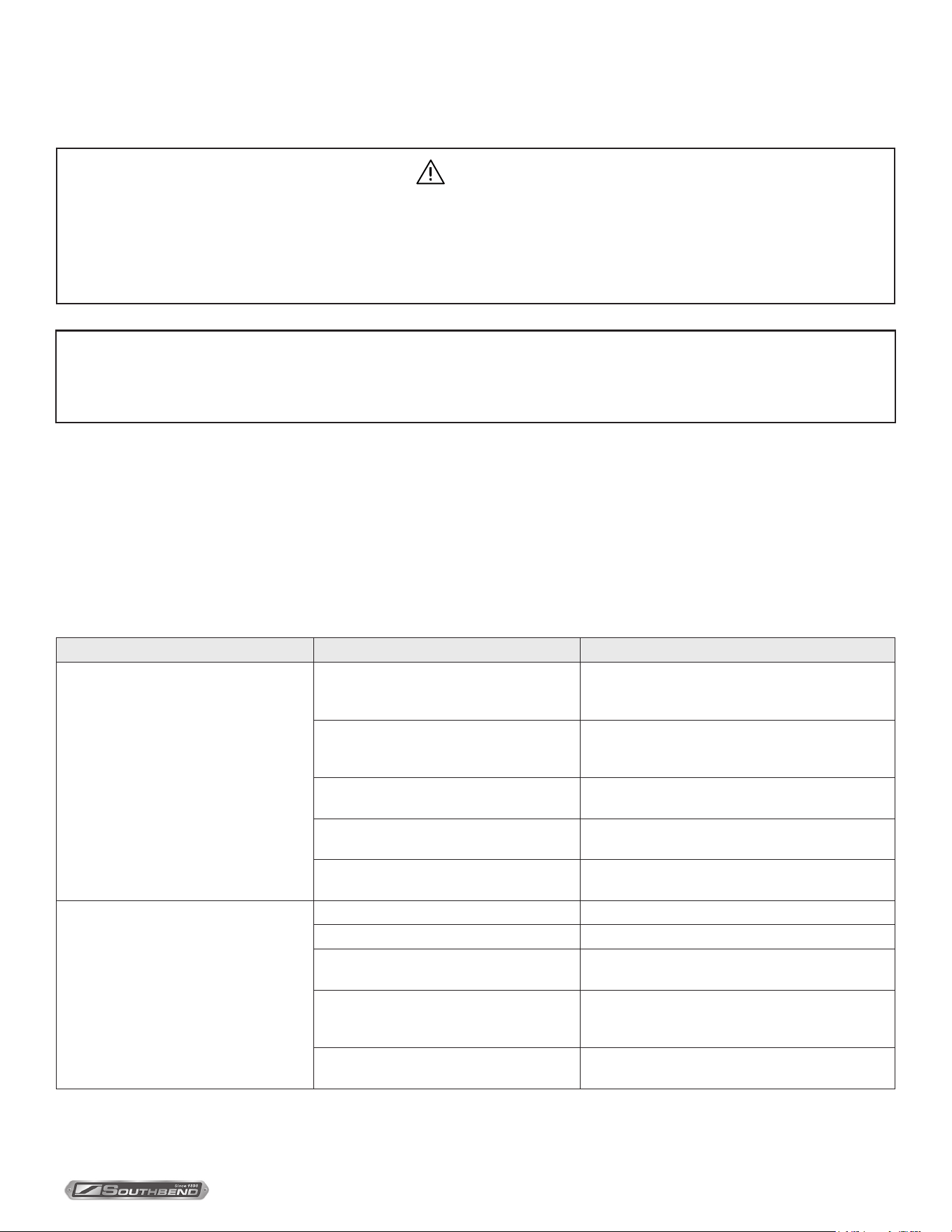
$21.00
TruVection Electric Convection Ovens
MANUAL SECTION CO
IMPORTANT FOR FUTURE REFERENCE
Please complete this information and retain this
manual for the life of the equipment:
Model #:
___________________________
Serial #:
___________________________
Date Purchased:
_____________________
WARNING
Improper installation, adjustment, alteration, service or maintenance can cause property damage, injury
or death. Read the installation, operating and maintenance instructions thoroughly before installing or
servicing this equipment.
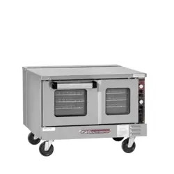
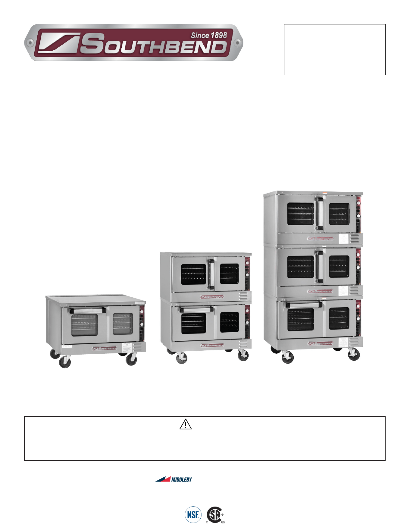
Model TVES/20SC
TruVection
Electric Convection Ovens
TVES/10SC, TVES/20SC & TVES/30SC
Installation & Operation Manual
SOUTHBEND
A Middleby Company
1100 Old Honeycutt Road Fuquay-Varina, North Carolina 27526 USA
www.southbendnc.com
Model TVES/10SC Model TVES/30SC
INSTALLATION & OPERATION MANUAL 1194659-ENGLISH, ELEC, REV 1 (11/21)
PAGE
2
OF 36
TruVection Electric Convection Ovens
SAFETY PRECAUTIONS
Before installing and operating this equipment, be sure everyone involved in its operation is fully trained and aware of
precautions. Accidents and problems can be caused by failure to follow fundamental rules and precautions.
The following symbols, found throughout this manual, alert you to potentially dangerous conditions to the operator,
service personnel, or to the equipment.
CAUTION
WARNING
NOTICE
This symbol warns of immediate hazards that will result in severe injury or death.
This symbol refers to a potential hazard or unsafe practice that could result in injury or death.
This symbol refers to a potential hazard or unsafe practice that could result in injury, product
damage, or property damage.
This symbol refers to information that needs special attention or must be fully
understood, even though not dangerous.
DANGER
Copyright © 2021 by Southbend Steam. All rights reserved. Published in the United States of America.
SPECIFICATIONS
WARNING
FIRE HAZARD
FOR YOUR SAFETY
Do not store or use gasoline or other ammable vapors and liquids in the vicinity of this or any other appliance.
Keep area around appliances free and clear of combustibles.
Purchaser of equipment must post in a prominent location detailed instructions to be followed in the event the
operator smells smoke. Obtain the instructions from the local electrician/installer.
NOTICE
Be sure this Operator’s Manual and important papers are given to the proper authority to retain for future reference.
NOTICE
This product is intended for commercial use only. NOT FOR HOUSEHOLD USE.
NOTICE
This manual should be retained for future reference.
INSTALLATION & OPERATION MANUAL 1194659-ENGLISH, ELEC, REV 1 (11/21)
PAGE
3
OF 36
TruVection Electric Convection Ovens
RETAIN THIS MANUAL FOR FUTURE REFERENCE.
Table of Contents
Specications ........................................................................................................................ 4
Installation ............................................................................................................................. 8
Operation .............................................................................................................................. 17
Cooking Hints........................................................................................................................ 20
Cleaning ................................................................................................................................ 23
Adjustments .......................................................................................................................... 25
Troubleshooting .................................................................................................................... 29
Table of Contents
Congratulations! You have purchased one of the finest pieces of heavy-duty commercial cooking equipment on
the market.
You will find that your new equipment, like all Southbend equipment, has been designed and manufactured to
meet the toughest standards in the industry. Each piece of Southbend equipment is carefully engineered and
designs are verified through laboratory tests and field installations. With proper care and field maintenance, you
will experience years of reliable, trouble-free operation. For best results, read this manual carefully.
Read these instructions carefully before attempting installation. Installation and initial startup should be performed by
a qualied installer. Unless the installation instructions for this product are followed by a qualied service technician (a
person experienced in and knowledgeable with the installation of commercial gas an/or electric cooking equipment) then
the terms and conditions on the Manufacturer’s Limited Warranty will be rendered void and no warranty of any kind shall
apply.
In the event you have questions concerning the installation, use, care, or service of the product, contact:
Southbend Technical Service
1100 Old Honeycutt Road
Fuquay Varina, North Carolina 27526 USA
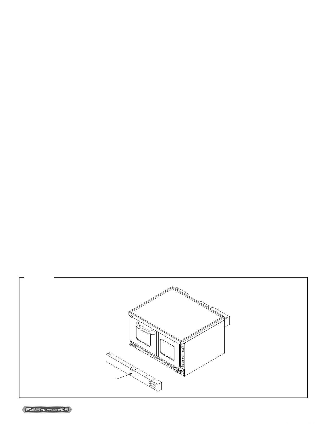
The serial plate is located on the interior side of the lower front panel, as shown below.
Serial Plate
(
inside panel)
FIGURE 1
INSTALLATION & OPERATION MANUAL 1194659-ENGLISH, ELEC, REV 1 (11/21)
PAGE
4
OF 36
TruVection Electric Convection OvensSpecifications
Specifications
NOTICE
The appliance, when installed, must be electrically grounded and comply with local codes, or in the absence of local codes, with
the National Electrical Code, ANSI/NFPA 70, or the Canadian Electrical Code, CSA C22.2, as applicable.
Southbend reserves the right to change specications and product design without notice. Such revisions do not entitle the buyer
to corresponding changes, additions, or replacements for previously purchased equipment.
This product is intended for commercial use only, not for household use.
Electricity Supply
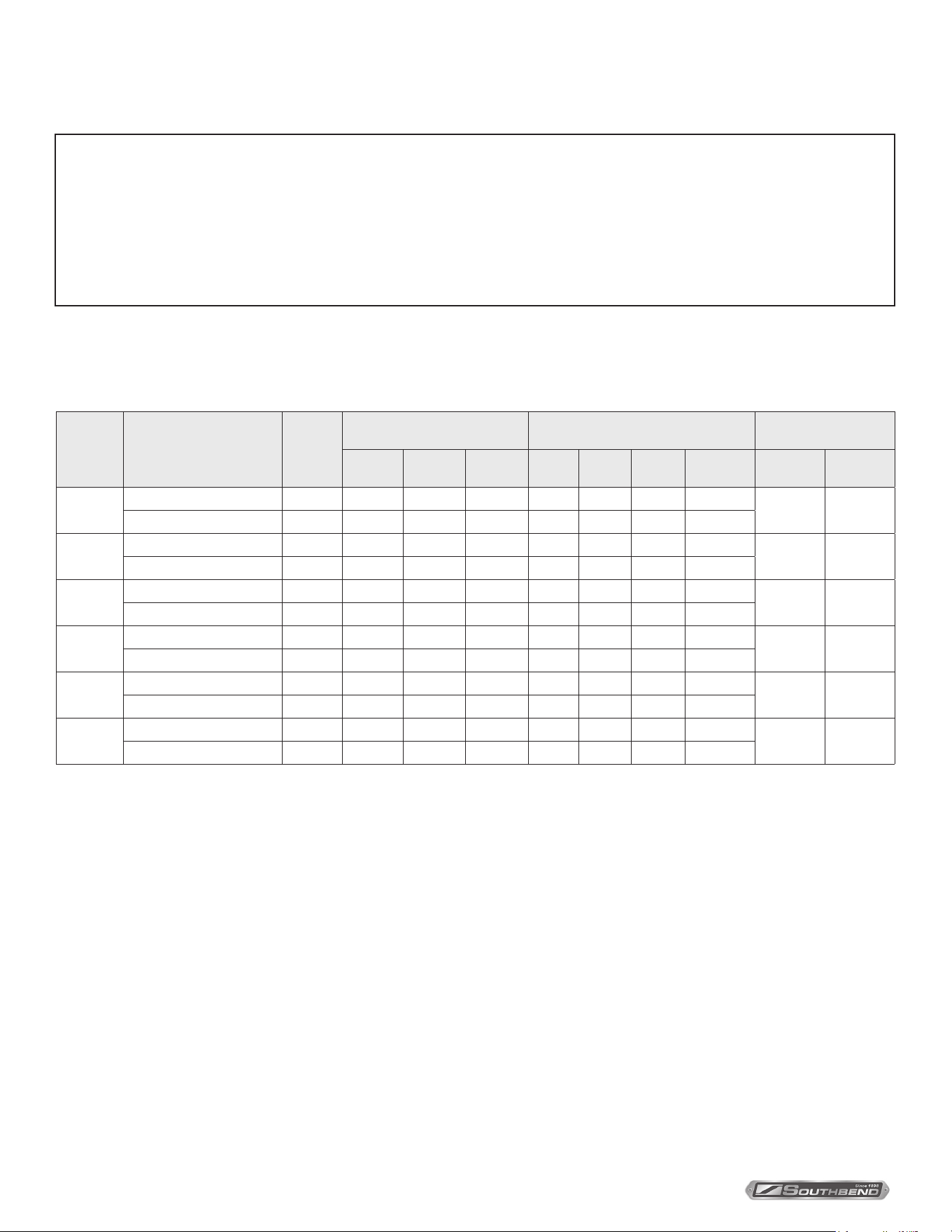
The following table lists the electricity supply requirements PER OVEN (double for dual-oven models; triple for
triple-oven models).
Supply
Voltage
Oven Component
Total
kW
3-Phase Loading (kW/phase) Nominal Amperes per Line-Wire
Minimum Supply
Wire (AWG) Size
L1-L2 L2-L3 L1-L3 L1 L2 L3
1-Phase
Total
3-Phase 1-Phase
480
Heating Elements 7.50 2.50 2.50 2.50 9.0 9.0 9.0 16.0
14 10
Motor & Controls 0.90 0.00 0.00 0.90 2.2 0.0 2.2 2.2
415
Heating Elements 7.50 2.50 2.50 2.50 10.4 10.4 10.4 18.1
12 10
Motor & Controls 0.90 0.00 L1-N 0.90 0.0 0.0 3.8 3.8
380
Heating Elements 7.50 2.50 2.50 2.50 11.4 11.4 11.4 20.0
12 8
Motor & Controls 0.90 0.00 L1-N 0.90 0.0 0.0 4.1 4.1
240
Heating Elements 7.50 2.50 2.50 2.50 18.0 18.0 18.0 31.3
10 8
Motor & Controls 0.90 0.00 0.00 0.90 3.8 0.0 3.8 3.8
220
(50Hz)
Heating Elements 7.50 2.50 2.50 2.50 19.7 19.7 19.7 34.1
10 8
Motor & Controls 0.90 0.00 0.00 0.90 4.1 0.0 4.1 4.1
208
Heating Elements 7.50 2.50 2.50 2.50 21.0 21.0 21.0 36.1
8 8
Motor & Controls 0.90 0.00 0.00 0.90 4.3 0.0 4.3 4.3
An electrical diagram is located on the side of the control panel assembly (see drawing on page 30). Electrical
diagrams can also be found in this manual beginning on page 30.
The electrical connections are made directly to the terminals of the heating-element contactor, which is located
inside the control-panel compartment on the right side of the oven. A circular opening sized for a strain-relief fitting
is located on the back of the oven near the right side (right as seen from the front of the oven, see illustration on
page 15). Models with two or three stacked ovens have a separate electrical connection for each oven.
Use 167°F (75°C) wire for all supply lines.
Ovens are shipped wired for either single-phase or three-phase operation, depending on which was specified on
the factory order. If necessary, an oven can be field-converted to use either single-phase or three-phase power
(see page 27).
INSTALLATION & OPERATION MANUAL 1194659-ENGLISH, ELEC, REV 1 (11/21)
PAGE
5
OF 36
TruVection Electric Convection Ovens Specifications
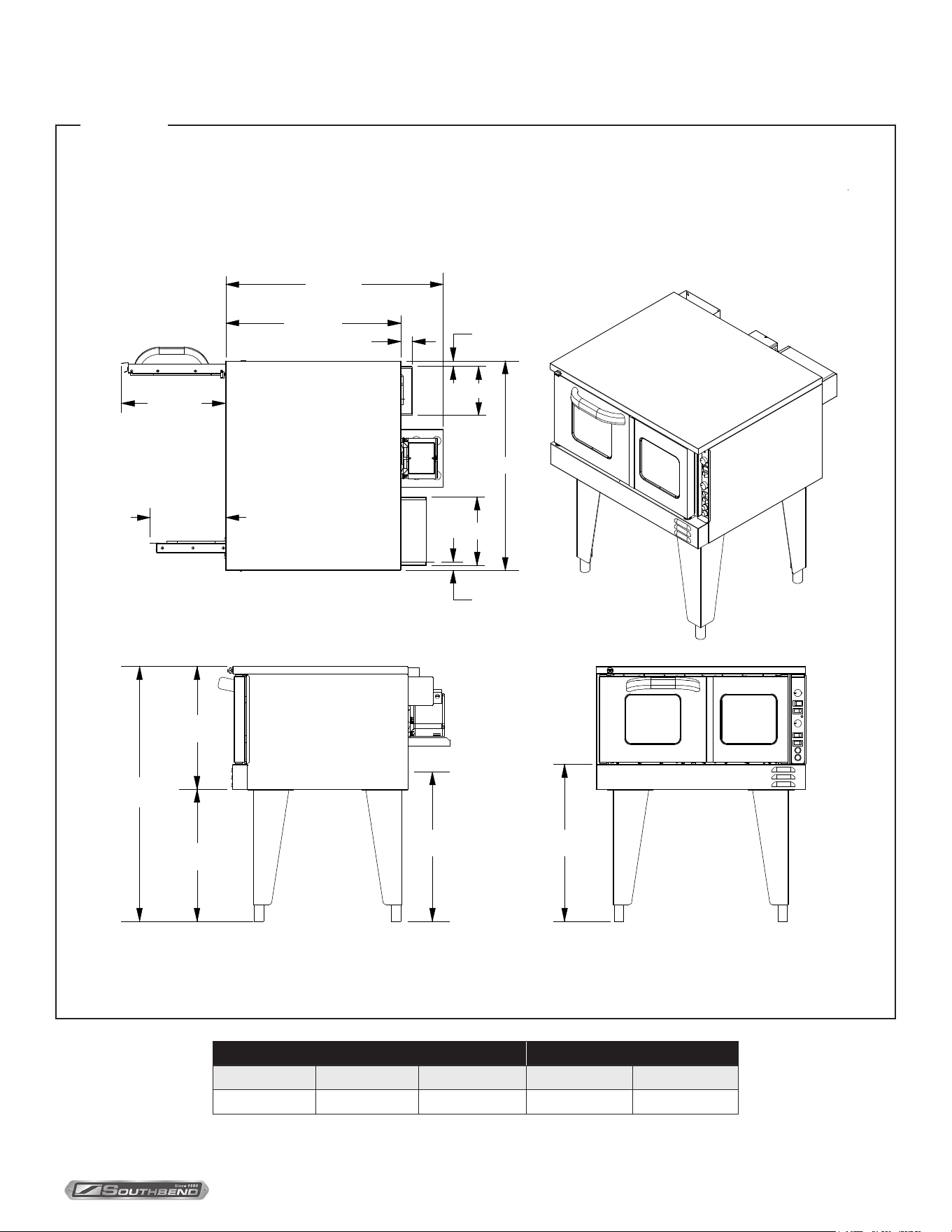
Exterior Dimensions
Single-Deck Ovens
18.6 (472)
13.5 (343)
22.7
(577)
43.9
(1115)
21.2
(538)
36.5 (928)
30.2 (767)
2.0 (51)
8.4 (213)
36.0 (914)
11.8 (300)
1.5 (38)
27.0
(686)
25.7
(653)
TOP VIEW
FRONT VIEWSIDE VIEW
Dimensions are shown in inches and (millimeters)
1.0 (25)
FIGURE 2
Oven Interior (per deck) Rack Clearance
Width Depth Height Width Depth
29" 21.5" 14" 28.19" 21"
INSTALLATION & OPERATION MANUAL 1194659-ENGLISH, ELEC, REV 1 (11/21)
PAGE
6
OF 36
TruVection Electric Convection OvensSpecifications
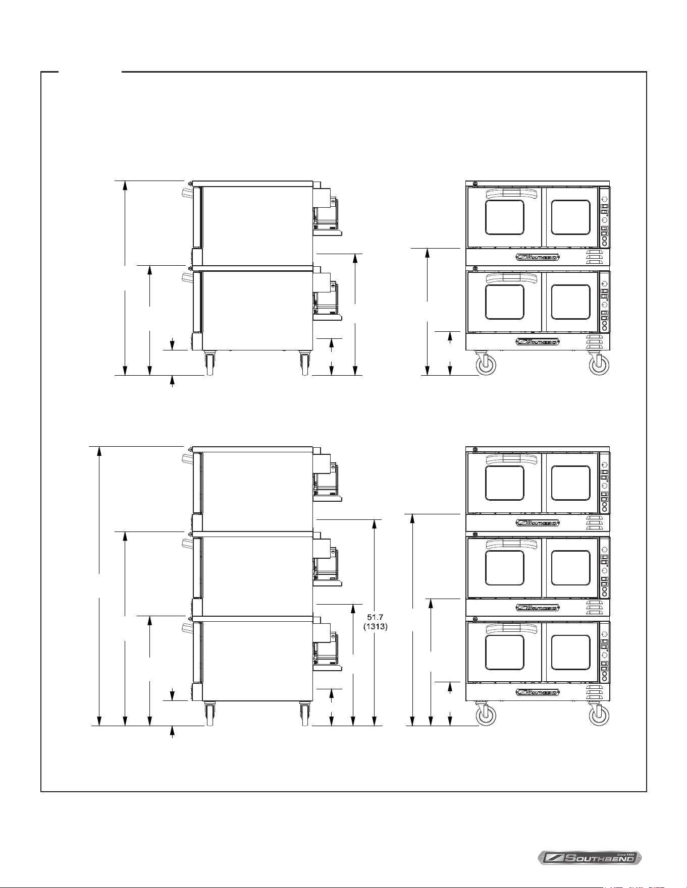
Double-Deck and Triple-Deck Ovens
27.5
(698)
48.7
(1237)
6.3
(159)
9.3 (236)
30.5
(775)
10.6
(270)
31.8
(808)
27.5
(698)
48.7
(1237)
69.9
(
1775)
6.3
(159)
30.5
(775)
31.8
(808)
9.3 (236)
10.6
(270)
53.0
(1346)
FRONT VIEWSIDE VIEW
FRONT VIEWSIDE VIEW
Dimensions are shown in inches and (millimeters)
FIGURE 3
INSTALLATION & OPERATION MANUAL 1194659-ENGLISH, ELEC, REV 1 (11/21)
PAGE
7
OF 36
TruVection Electric Convection Ovens Specifications
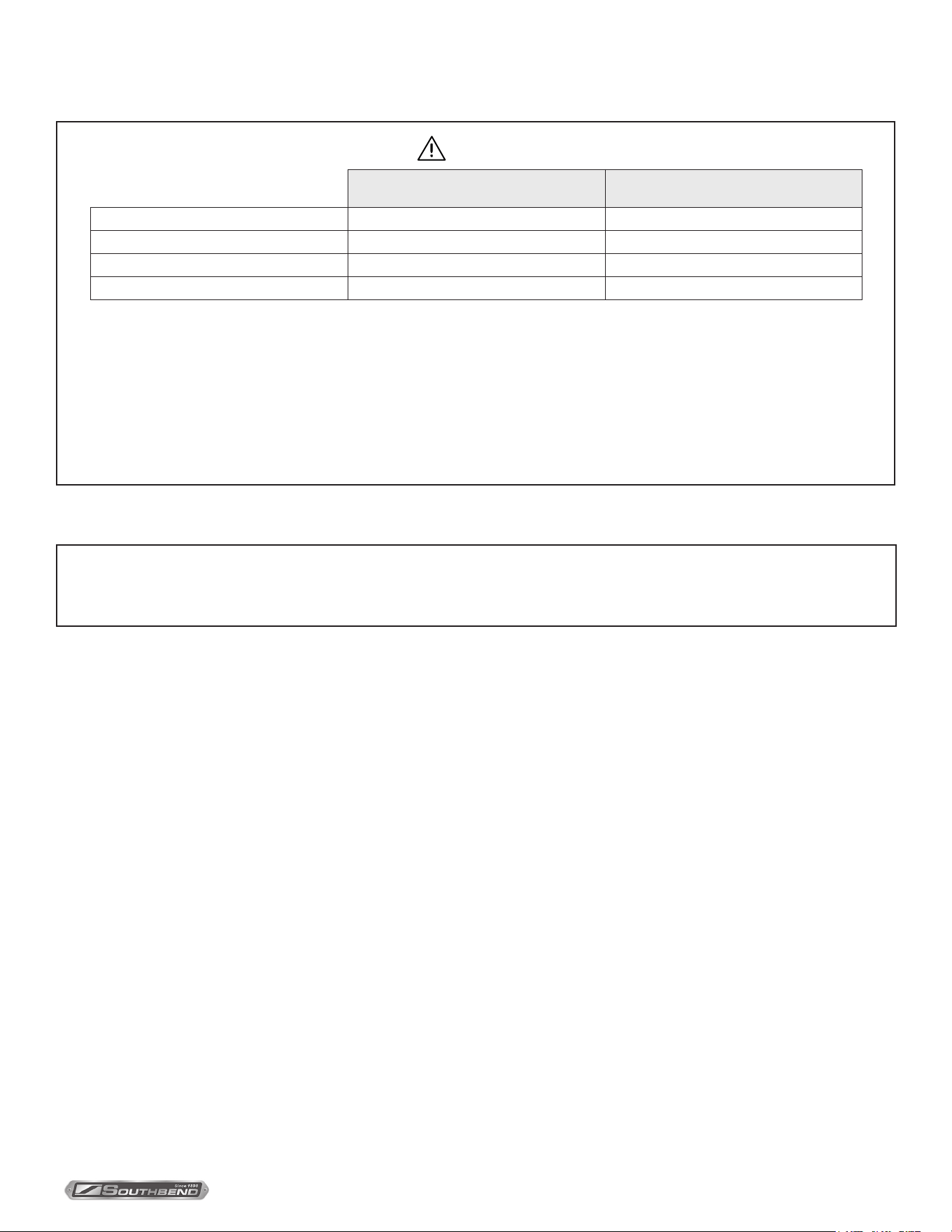
Minimum Clearances
WARNING
Minimum Clearance from
Combustible Construction
Minimum Clearance from
Non-Combustible Construction
Back 2" 2"
Right Side 0" 0"
Left Side 0" 0"
Floor 0" 0
Adequate clearance must be provided in the aisle to allow the doors to open suciently to permit the removal of
the racks and for serviceability.
Although no clearance is required behind the motor on the rear of the oven, care must be taken to provide
adequate air circulation to prevent the motor from overheating.
Do not locate the oven adjacent to any high heat or grease-producing piece of equipment, such as a range top,
griddle, fryer, etc., that could allow radiant heat to raise the exterior temperature of the oven above 130°F (54°C).
DO NOT MOUNT ABOVE OTHER COOKING EQUIPMENT.
Ventilation
NOTICE
Proper ventilation is the owner’s responsibility. Any problem due to improper ventilation will not be covered by the
warranty.
The Southbend warranty does not require that electric TruVection ovens be installed under a ventilation canopy. However,
local codes may require installation under a ventilation canopy.
If a ventilation canopy is used, it is recommended that a canopy extend 6” past the appliance and that the bottom edge be
located 6’6” from the oor. Filters should be installed at an angle of 45° or more from the horizontal. This position prevents
dripping grease and facilitates collecting the run-o grease in a drip pan, unusually installed with a lter.
If an exhaust fan is used, it should be installed at least 2” above the ue opening at the top of the unit. A strong exhaust
fan tends to create a vacuum in the room. Fresh air openings approximately equal to the fan area will relieve such a
vacuum. In case of unsatisfactory performance on any appliance, check the appliance with the exhaust fan in the “OFF”
position. Do this only long enough to check equipment performance. Then turn the exhaust fan back on and let it run to
remove any exhaust that may have accumulated during the test.

INSTALLATION & OPERATION MANUAL 1194659-ENGLISH, ELEC, REV 1 (11/21)
PAGE
8
OF 36
TruVection Electric Convection OvensInstallation
Installation Instructions
NOTICE
These installation procedures must be followed by qualied personnel or warranty will be void.
Local codes regarding installation vary greatly from one area to another. The National Fire Protection Association,
Inc. states in its NFPA 96 latest edition that local codes are the “authority having jurisdiction” when it comes to
installation requirements for equipment. Therefore, installations should comply with all local codes.
This appliance, when installed, must be electrically grounded in accordance with local codes, or in the absence
of local codes, with the National Electrical Code, ANSI/NFPA 70 or the Canadian Electrical Code, CSA C22.2, as
applicable.
Step 1: UNPACKING
IMMEDIATELY INSPECT FOR SHIPPING DAMAGE
All containers should be examined for damage before and during unloading. The freight carrier has assumed
responsibility for its safe transit and delivery. If damaged equipment is received, either apparent or concealed, a
claim must be made with the delivering carrier.
Apparent damage or loss must be noted on the freight bill at the time of delivery. The freight bill must then be signed
by the carrier representative (Driver). If the bill is not signed, the carrier may refuse the claim. The carrier can supply
the necessary forms.
A request for inspection must be made to the carrier within 15 days if there is concealed damage or loss that is
not apparent until after the equipment is uncrated. The carrier should arrange an inspection. Be certain to hold all
contents plus all packing material.
1. Cut banding straps and remove packing material.
2. Remove tie-down strap holding oven to wooden skid.
3. If you are installing a single-deck oven, go to Step 2a.
If you are installing a double-deck or triple-deck oven, go to Step 2b.
INSTALLATION & OPERATION MANUAL 1194659-ENGLISH, ELEC, REV 1 (11/21)
PAGE
9
OF 36
TruVection Electric Convection Ovens Installation
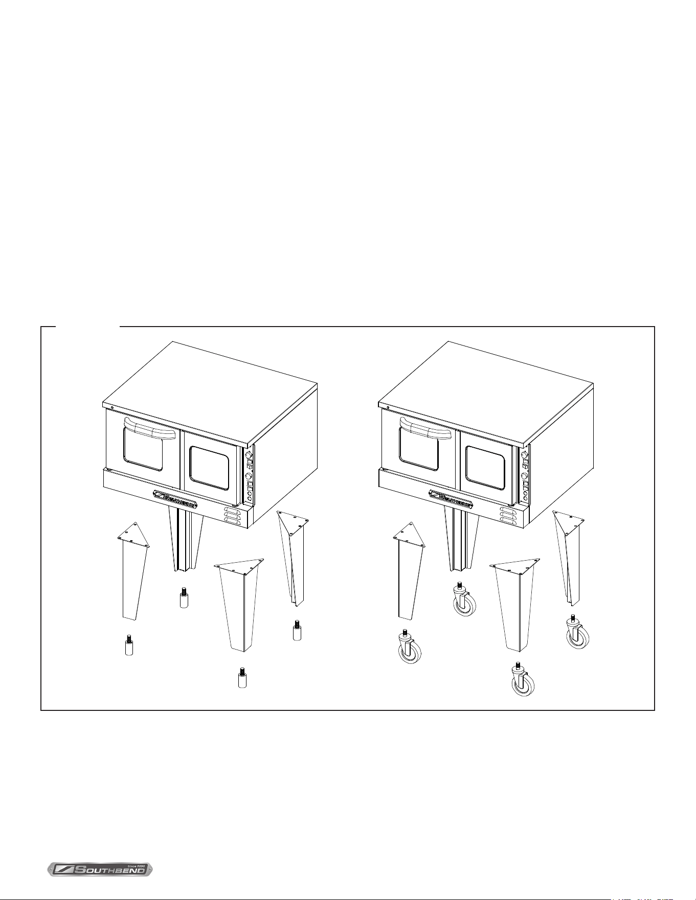
Step 2a: Installation of Legs on Single-Deck Ovens
1. Raise oven suciently to allow clearance for the legs to be attached. Use of a lift truck or other mechanical lifting
means is recommended. For safety, “shore up” and support the oven with an adequate blocking arrangement
strong enough to support the load. (If it is absolutely necessary to rest the oven on its side, rest it on its left side.
Take care to protect the nish on the left side, and to prevent the weight from resting on the motor on the back.)
2. Attach the legs to the bottom corners of the oven using the provided machine screws, at washers, and lock
washers. Each leg is secured by ve screws. The mounting holes are pre-drilled and threaded.
3. Screw into the bottom of each leg either an adjustable foot or a caster (depending on which option was ordered). If
attaching casters, the two casters with brakes should be attached to the front legs.
4. Lower the oven gently onto a level surface. Never drop or allow the oven to fall.
5. Use a level to make sure that the oven is level. The adjustable feet can be screwed in or out to lower or raise each
corner of the oven.
6. Go to Step 4 on page 15.
FIGURE 4
INSTALLATION & OPERATION MANUAL 1194659-ENGLISH, ELEC, REV 1 (11/21)
PAGE
10
OF 36
TruVection Electric Convection Ovens
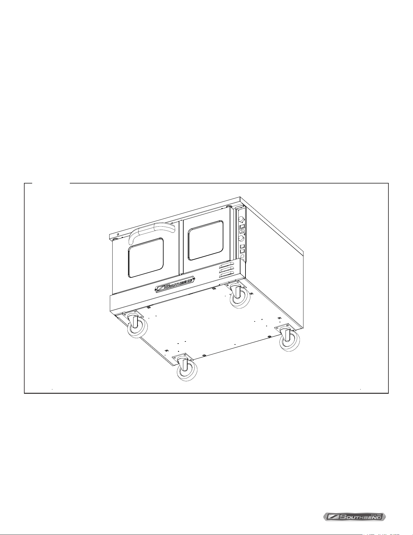
Step 2b: Installation of Legs on Double-Deck or Triple-Deck Ovens
Double-deck (or triple-deck) ovens can be shipped either already bolted together, or as two (or three) separate ovens to
be bolted together after delivery. In either case, the oven that is (or will be) the bottom oven will have leg pads already
bolted to the bottom corners of the oven. Do the following:
1. Raise oven suciently to allow clearance for the legs to be attached. Use of a lift truck or other mechanical lifting
means is recommended. For safety, “shore up” and support the oven with an adequate blocking arrangement strong
enough to support the load. (If it is absolutely necessary to rest the oven on its side, rest it on its left side. Take care to
protect the nish on the left side, and to prevent the weight from resting on the motor on the back.)
2. Screw into the center of each leg pad either an adjustable leg or a caster (depending on which option was ordered). If
attaching casters, the two casters with brakes should be attached to the front leg pads.
3. Lower the oven gently onto a level surface. Never drop or allow the oven to fall.
4. Use a level to make sure that the oven is level. The adjustable legs can be screwed in or out to lower or raise each
corner of the oven.
FIGURE 5
Installation
INSTALLATION & OPERATION MANUAL 1194659-ENGLISH, ELEC, REV 1 (11/21)
PAGE
11
OF 36
TruVection Electric Convection Ovens
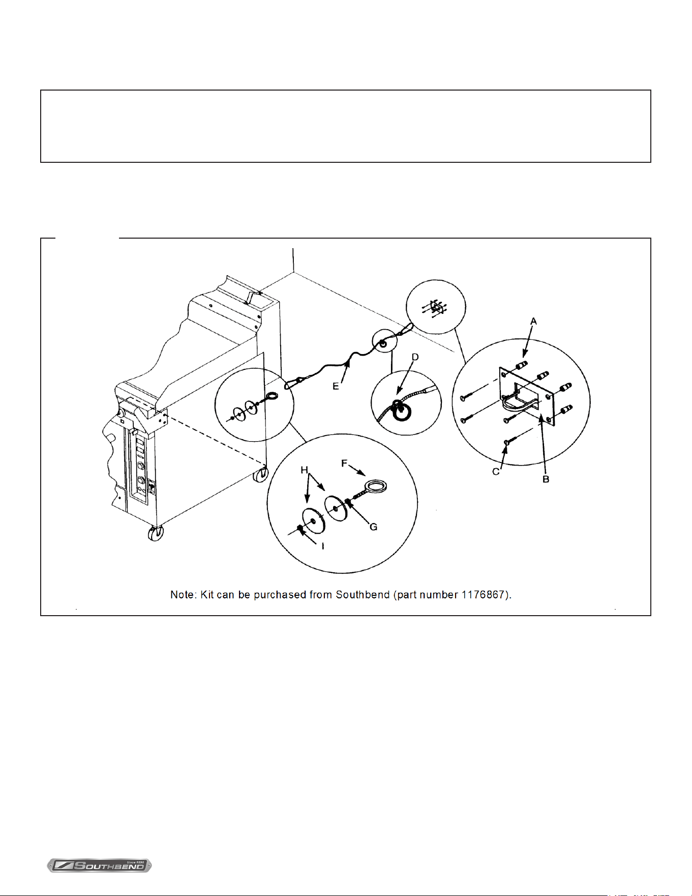
FIGURE 6
Step 3: Installation of Restraint (Only for Ovens with Casters)
NOTICE
For an appliance equipped with casters, adequate means must be provided to limit the movement of the appliance
without depending on or transmitting stress to the electrical conduit. The restraining means should be attached to
a frame member on the back of the unit and the appliance should be installed using exible conduit.
1. Secure the restraining-device bracket (item “B” in the following illustration) to a wall stud located as close as possible
to the appliance connector inlet and outlet connections. Use four #12 screws (items “C”) and plastic anchors (items
“A”) if necessary.
2. Install eye-bolt (item “F”) to a frame member on the rear of the equipment. After checking carefully behind the frame
member for adequate clearance, drill a 1/4” hole through the frame member.
3. Thread hex nut (item “G”) and slide the washer (item “H”) onto the eye-bolt. Insert the eye-bolt through the 1/4” drilled
hole and secure with a washer (item “H”) and nylon lock nut (item “I”).
4. Using the spring-loaded snap hooks, attach the restraining device to the bracket and the eye-bolt.
5. Using the cable clamp (item “D”), adjust the restraining device extended length to prevent over-bending or kinking of
the appliance connector.
Installation
INSTALLATION & OPERATION MANUAL 1194659-ENGLISH, ELEC, REV 1 (11/21)
PAGE
12
OF 36
TruVection Electric Convection Ovens
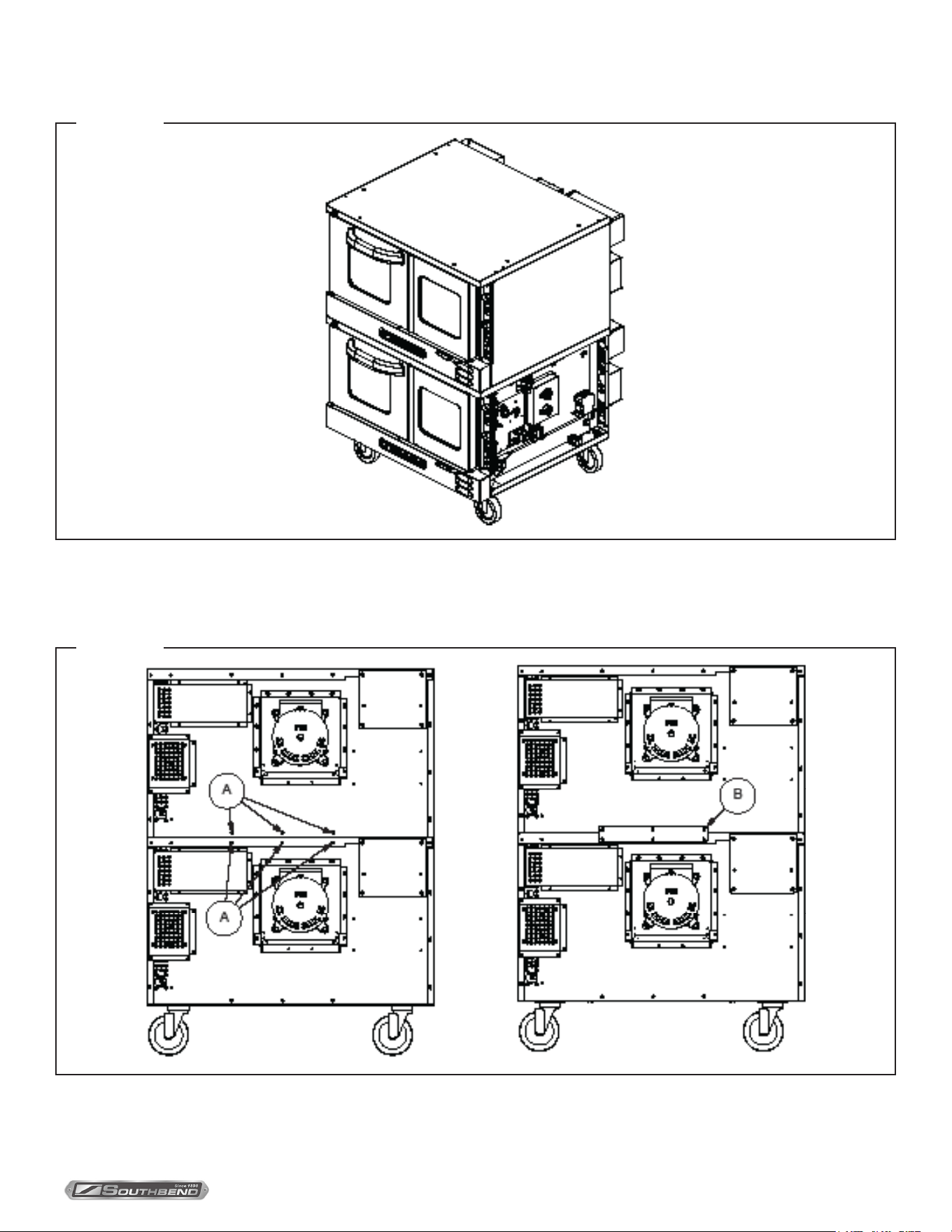
Step 4: Stack Ovens (if necessary)
Double-deck (or triple-deck) ovens can be shipped already assembled, but can instead be shipped as two (or three)
single-deck ovens to be stacked in the eld. Also, ovens that were originally ordered as single ovens can be stacked in the
eld (additional parts are required). This installation step describes the procedure for stacking two single-deck ovens to
form a double-deck oven. For a triple-deck oven, repeat this step.
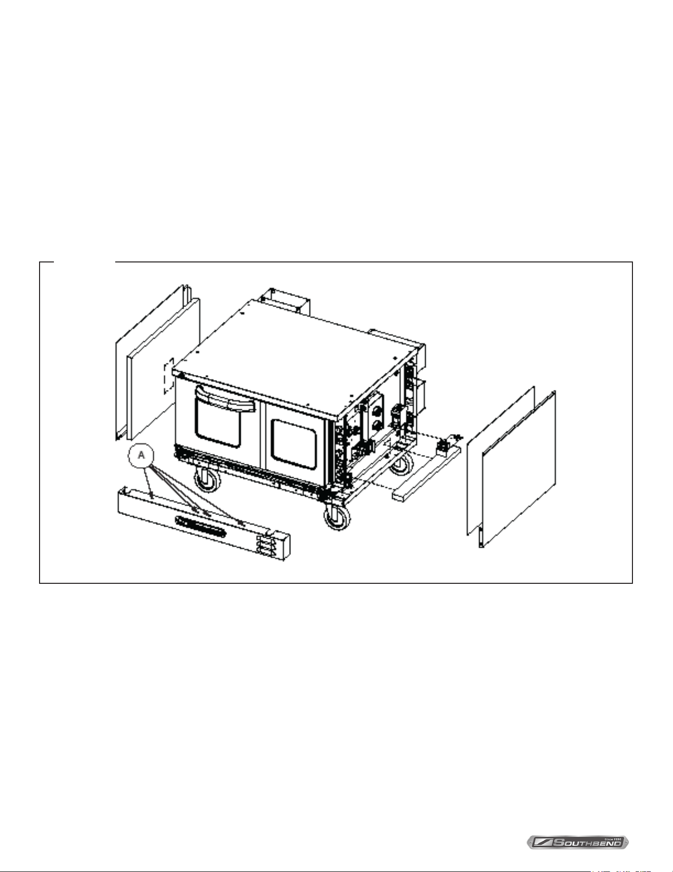
1. Uncrate the ovens. Identify the oven that will be the bottom unit (it will be the oven with pads attached to the bottom
corners). Attach the legs (or casters), to the lower oven as described in Step 2b on page 10.
2. If the oven that will be the top unit was NOT ordered as part of a double-deck or triple-deck oven, remove the four
mounting legs or casters from the bottom of that oven.
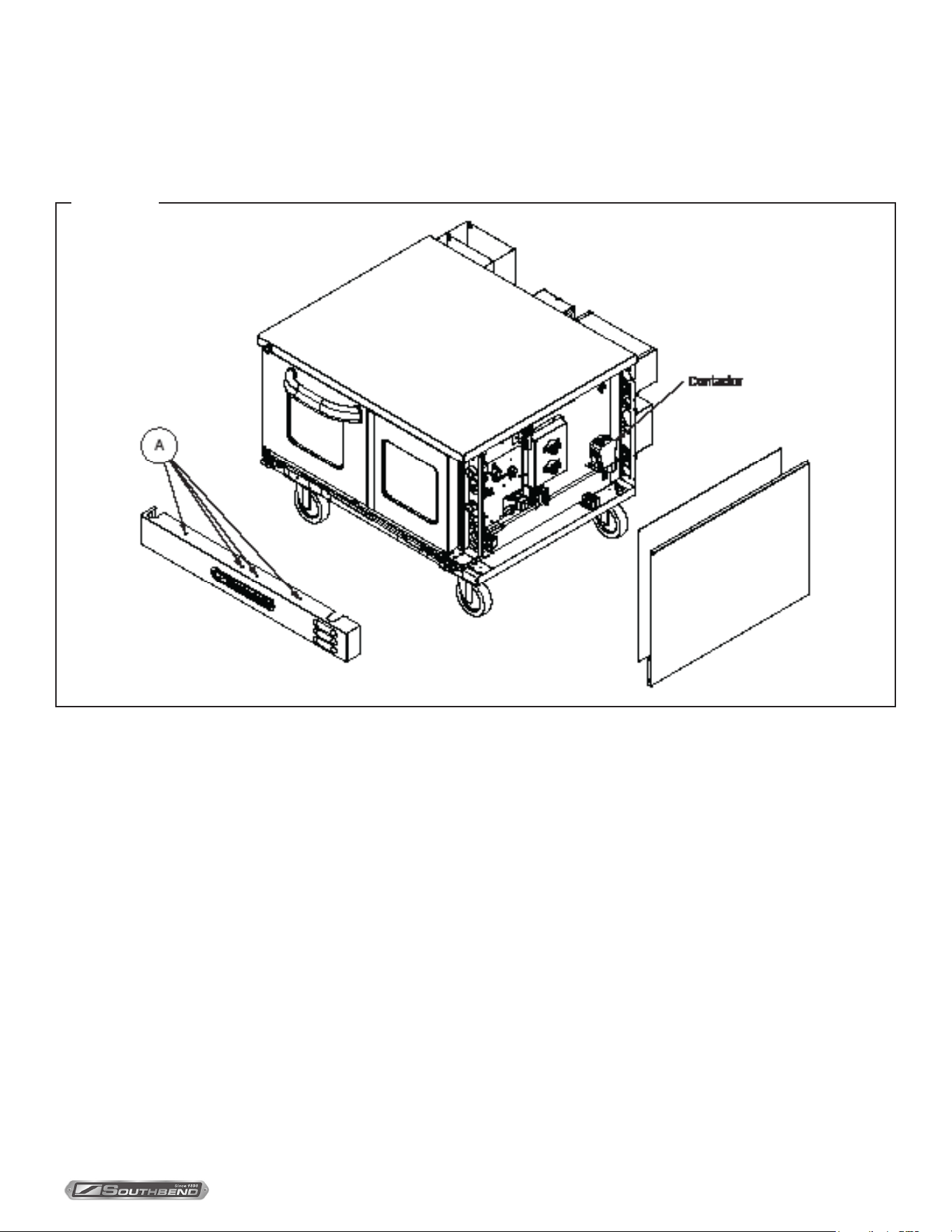
3. Locate and remove the four screws that secure the front panel, (items “A” in the drawing below). Lift up the panel and
pull it forward to remove it, then set it aside.
FIGURE 7
4. Locate and remove the screws that secure the left and right side panels to the oven. Remove panels and insulation
and set them aside as shown in the picture above.
5. Remove the terminal block mounting plate and lower insulation strip on right side of unit for access to holes.
6. If the oven that will be the bottom unit was NOT ordered as part of a double-deck or triple-deck oven, holes will need
to be drilled in the existing top, or an optional mounting top can be ordered. The panel sides and insulation will also
need to be removed from lower oven to allow access for bolting the units together.
Installation
INSTALLATION & OPERATION MANUAL 1194659-ENGLISH, ELEC, REV 1 (11/21)
PAGE
13
OF 36
TruVection Electric Convection Ovens
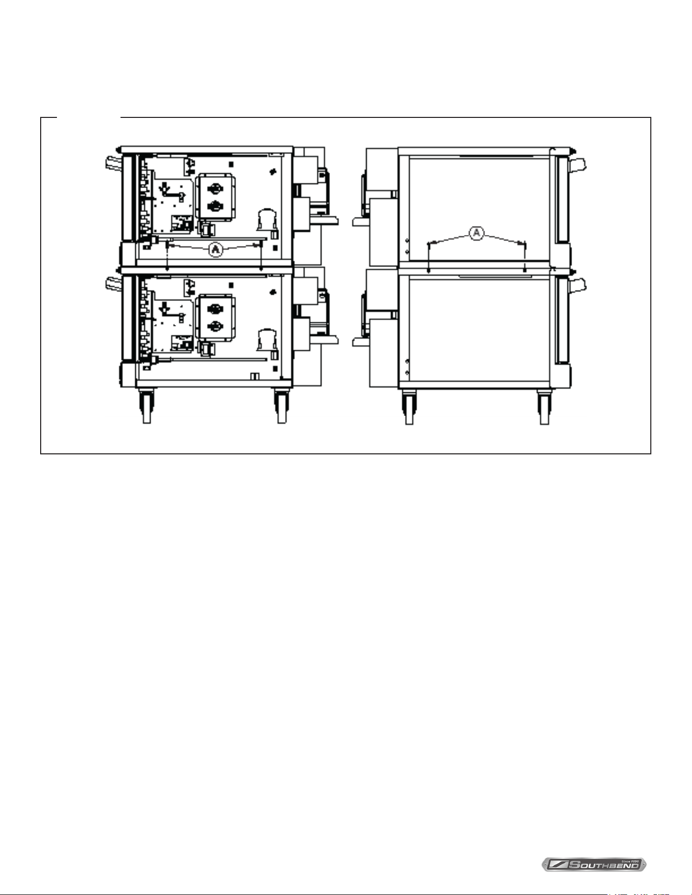
7. Lift the top oven onto the lower oven and position it as shown in the drawing below.
FIGURE 8
8. Move to the rear of the ovens and remove the six screws shown as items “A” in the left-hand drawing below. Position
the tie bracket (item “B”) as shown in the right-hand drawing below. Re-insert the screws that you just removed
through the holes in the tie bracket, but do not tighten them yet.
FIGURE 9
Installation
INSTALLATION & OPERATION MANUAL 1194659-ENGLISH, ELEC, REV 1 (11/21)
PAGE
14
OF 36
TruVection Electric Convection Ovens
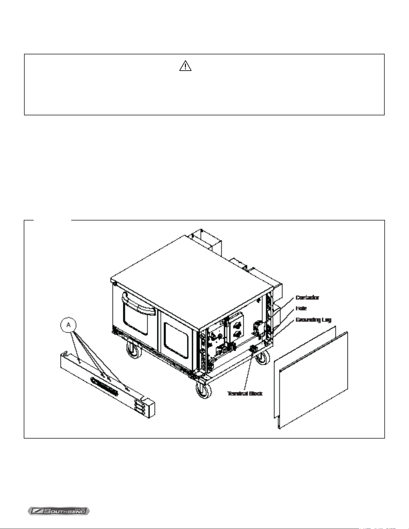
9. Insert two 1/4-20 bolts on each side (items “A” in the following diagram), as shown in the pictures below. Screw them
down into the threaded inserts of the optional mounting top on the lower unit, or use a bolt and nut to secure if holes
were manually drilled.
FIGURE 10
10. Reinstall Terminal Block Mounting Plate, insulation, exterior side panels and lower front panel that were removed in
Steps 3, 4, & 5 of this procedure.
Installation
INSTALLATION & OPERATION MANUAL 1194659-ENGLISH, ELEC, REV 1 (11/21)
PAGE
15
OF 36
TruVection Electric Convection Ovens
Step 5: Connect Electricity Supply
WARNING
ELECTRICAL GROUNDING INSTRUCTIONS
This appliance, when installed, must be electrically grounded in accordance with local codes, or in the absence
of local codes, with the National Electrical Code, ANSI/NFPA 70 or the Canadian Electrical Code, CSA C22.2, as
applicable.
Ovens are shipped wired for either single-phase or three-phase power according to the original factory order. Wiring
diagrams are located on the side of the control panel assembly, as well as in this manual (beginning on page 30). Be sure
that the input voltage and phase match the requirements shown on the serial plate, which is located inside the lower front
panel.
Conversion between single-phase and three-phase power can be performed in the eld (see page 27).
The oven must be adequately grounded.
Use 167°F (75°C) wire for all supply lines.
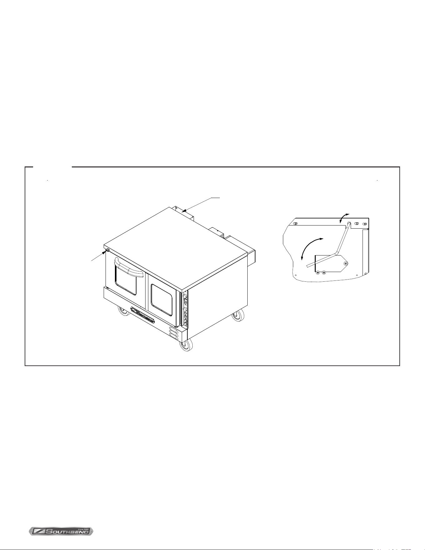
The following drawing shows the locations of items referred to in the following procedure.
FIGURE 11
1. CHECK THAT THE POWER SUPPLY CIRCUIT BREAKER IS OPEN.
2. Locate and remove the four screws that secure the lower front panel (items “A” in the drawing above). Lift up the
panel and pull it forward to remove it, then set it aside.
3. To connect the supply wires, locate and remove the ve screws (3 back, 2 front), that secure the right side panel to
the oven.
Installation

INSTALLATION & OPERATION MANUAL 1194659-ENGLISH, ELEC, REV 1 (11/21)
PAGE
16
OF 36
TruVection Electric Convection Ovens
4. Route the supply wires and the grounding wire through the hole on the back of the oven. Use a strain-relief tting.
5. Attach each supply wire to the appropriate terminal of the contactor or terminal block (according to the wiring
diagrams starting on page 30), taking care not to disconnect any wires that may already be connected to the contactor
or terminal block.
6. Insert the ground wire into the grounding lug and tighten the screw.
7. Check that all connections match the wiring diagram and are tight.
8. Reattach the right-side panel and insulation; and the lower-front panel.
Step 6: Check the Installation
1. Check that all screws and bolts are tightened.
2. Move the oven into the position at which it will be operated.
3. Check that the oven is level. If not, adjust the legs.
4. Check that the appropriate clearances are satised (see page 7).
5. Turn-on supply power and check oven for proper operation.
Installation
INSTALLATION & OPERATION MANUAL 1194659-ENGLISH, ELEC, REV 1 (11/21)
PAGE
17
OF 36
TruVection Electric Convection Ovens Operation
Operating Instructions
Operating the Controls
A convection oven is a dierent type of oven that oers many features and advantages to the food service operation. The
additional capabilities and features of the oven require some learning. However, the operation of the oven is not dicult to
understand or control once you have some practice.
Moisture Vent
Each oven has a moisture vent that is opened and closed using the small knob located near the top left corner of the front
panel of the oven (see illustration below). Usually the vent is kept open to allow moisture to escape. Close the vent (turn
the knob clockwise) when doing ne baking.
Turning the control knob opens
or closes moisture vent (shown
below with its cover removed).
Location of
Moisture Vent
M
oisture Vent
Control Knob
FIGURE 12
INSTALLATION & OPERATION MANUAL 1194659-ENGLISH, ELEC, REV 1 (11/21)
PAGE
18
OF 36
TruVection Electric Convection OvensOperation
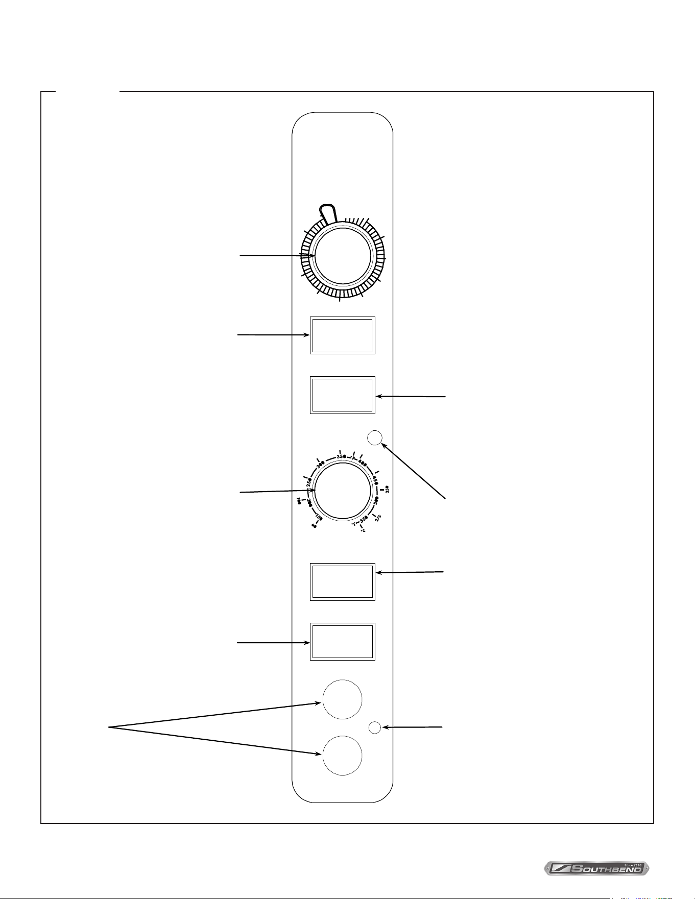
Control Panel
POWER
COOK TIMER (MIN.)
FAN MODE
HEAT ON
COOLCOOK
COOK TEMPERATURE
OFF
LOW
LIGHTS
FAN SPEED
ON
HI
°
C
2
2
5
2
0
0
5
2
1
0
5
1
5
7
1
0
1
10
45
50
55
F
F
O
40
35
30
25
20
15
2
3
4 5
Power Switch
Switch ON to use the oven, switch
OFF when done using the oven.
Cook Timer
T
urn knob to set a time duration. An
alarm will sound when the timer
runs out. The timer is a reminder to
the user; the timer does not
control the oven.
Cook Temperature Control
T
urn knob to select desired cooking
t
emperature. The Heat On indicato
r
will go out when the oven reaches
the set temperature, and will cycle
on and off as the elements operate
to maintain the set cooking
temperature.
Fan Mode
In COOK mode, the fan runs
c
ontinuously except when the doors
are open. The fan does NOT cycle
with the operation of the elements.
In COOL mode, the fan runs
continuously even if the doors are
open. Since the elements will not
operate if the oven doors are open,
to rapidly cool the oven after
cooking is completed, open the
doors and switch the fan mode to
COOL.
Oven Interior Light Switch
On ovens equipped with an oven
interior light, press to turn on the
light. The light remains on for as
long as the switch is held.
Heat-On Indicator
Indicator is lit when the elements
are operating.
Fuses
W
A
R
N
I
N
G
Warning Light
Indicator is lit if and when unit
malfunctions. Turn off or disconnect
power from power supply and have
the unit serviced by a qualified
technician.
Fan Speed
Use to select fan speed (HI or
LOW). The appropriate speed is
determined by the type of food
being cooked.
FIGURE 13

INSTALLATION & OPERATION MANUAL 1194659-ENGLISH, ELEC, REV 1 (11/21)
PAGE
19
OF 36
TruVection Electric Convection Ovens Operation
TruVection ovens operate much like a standard oven: you turn the oven ON and select a cooking temperature. Two
additional controls are used to control the fan (as described below).
The timer is a reminder to you of when to remove food from the oven. The timer does NOT control the temperature of the
oven.
To cook, do the following:
1. Turn the oven ON using the Power Switch at the top of the control panel.
2. Select the desired fan speed using the Fan Speed switch. The appropriate fan speed (HI or LOW) depends on the
type of food being cooked.
3. Switch the Fan Mode switch to COOK. The fan will run continuously when the oven doors are closed (the fan does not
cycle on and o with the elements). (If this switch is set to COOL the only dierence is that the fan will continue to run
when the oven doors are open.)
4. Set the cooking temperature by turning the Cook Temperature Control until the indicator mark on the knob is pointed
to the desired cooking temperature. The Heat On indicator will light when the elements are on, and will remain on
while the oven preheats.
5. Wait until the Heat On indicator has come on and gone out three times. At that time the oven will have reached the set
cooking temperature.
6. Open the oven doors, load the product into the oven, and close the doors.
7. You can use the Cook Timer as a reminder of when the remove the load from the oven. If so desired, turn the Cook
Timer knob until the indicator mark points to the desired cooking time (up to 55 minutes). The timer knob will rotate
counterclockwise as the timer runs down, indicating how much time remains. You can turn the knob while cooking to
increase or decrease the remaining time. When the timer runs out, a buzzer will sound for a short time, then turn itself
o. (To immediately silence the buzzer, turn the Cook Timer knob to the OFF position.) The timer is a reminder to you;
the timer does not control the oven.
If you open the oven doors while in COOK mode, the elements and fan will shut o until the doors are closed.
However, the timer will continue running even if the doors are open.
For ovens that are equipped with an oven interior light, to turn on the light press and hold the switch located at the
bottom of the control panel.
8. When the load has nished cooking, you can rapidly cool the load by opening the oven doors (which will shut o the
elements) and switching the Fan Mode to COOL (which will cause the fan to run even though the doors are open). For
the most rapid cooling, also switch the Fan Speed switch to HI.
9. When you are done cooking, turn the Cook Temperature control to the lowest setting (fully counterclockwise) and
switch the Power Switch to OFF.
WARNING
If the malfunction light turns on, the appliance is malfunctioning. Turn o or disconnect power from power supply and
have the unit serviced by a qualied technician.
INSTALLATION & OPERATION MANUAL 1194659-ENGLISH, ELEC, REV 1 (11/21)
PAGE
20
OF 36
TruVection Electric Convection Ovens
Cooking Hints
Cooking Hints
In a standard (non-convection) oven, the air is relatively still and an insulating layer of moisture surrounds the cooking
food product. In a convection oven, the fan-blown circulating air strips away this insulating layer allowing the heat to
penetrate faster for quicker baking and roasting. Hence, in a convection oven cooking procedures and techniques may
require some modication for successful results. As a general rule, the cooking time will be shorter and the cooking
temperature will be 25°F to 75°F lower than those called for in recipes for a standard oven.
Time & Temperature
Time and temperature are important. The “Guide to Times and Temperatures” later in this section is a starting point. The
actual best cooking time and temperature will depend on such factors as size of load and mixture of recipe (particularly
moisture). Once an appropriate time and temperature has been established for a particular product and load, you will nd
the result of succeeding loads to be similar.
Overloading
Do NOT overload the oven. The size of the load that can be cooked satisfactorily depends largely on the particular
product. As a rule, three racks can be successfully used for shallow cakes, cookies, pies, etc. For deeper cakes (such as
angel food), use only one or two racks because of the size of the pan and the space required for rising. For hamburger
patties, sh sticks, cheese sandwiches, etc., three or four racks and pans is usually satisfactory.
Helpful Suggestions
Here are some suggestions that will assist in getting the best possible performance from a convection oven:
• Pre-heat the oven thoroughly before use.
• When re-thermalizing frozen products, pre-heat the oven to 50°F higher than the planned cooking temperature. After
loading, reduce the temperature setting to the appropriate cooking temperature.
• Space the racks and pans as evenly as possible to allow air circulation.
• Center the load on the racks to allow for proper air circulation around the sides. Do not cover the racks completely with pans.
• Do not use a deep pan for shallow cakes or cookies, etc. Air circulation across the surface of the product is essential.
WARNING
THE USE OF ALUMINUM FOIL CAN CAUSE HEAT DISTRIBUTION PROBLEMS IN OVENS. EXTREME CARE
MUST BE USED WHEN PLACING ALUMINUM FOIL IN THE OVEN TO ENSURE THAT IT DOES NOT BLOCK OR
CHANGE THE AIR FLOW. THE USE OF ALUMINUM FOIL MAY VOID THE PRODUCT WARRANTY IF ITS USE IS
ASCERTAINED TO BE A PROBLEM.
INSTALLATION & OPERATION MANUAL 1194659-ENGLISH, ELEC, REV 1 (11/21)
PAGE
21
OF 36
TruVection Electric Convection Ovens Cooking Hints
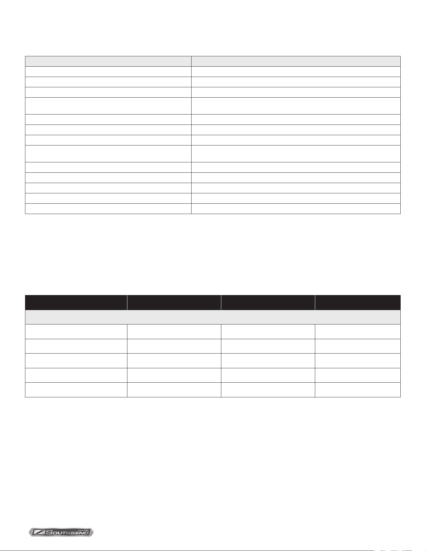
Cooking Problems and Solutions
If… then…
Cakes are dark on the sides and not done in the center… lower oven temperature.
Cake edges are too brown… reduce number of pans or lower oven temperature.
Cakes have a light outer color… raise temperature.
Cakes settle slightly in the center…
bake longer or raise oven temperature slightly. Do not open doors except to
load or unload product.
Cakes ripple… do not overload pans or use batter that is too thin.
Cakes are too coarse… lower oven temperature.
Pies have uneven color… reduce number of pies per rack or eliminate use of bake pans.
Brown sugar topping or meringue blows o…
after oven is preheated, turn o oven and put product in oven until topping
sets, then turn oven back on.
Rolls have uneven color… reduce number or size of pans.
Meats are browned and not done in center… lower oven temperature and roast longer.
Meats are well done and not browned… raise temperature. Limit amount of moisture.
Meats develop hard crust… reduce temperature or place pan of water in oven.
Excessive meat shrinkage occurs… lower oven temperature.
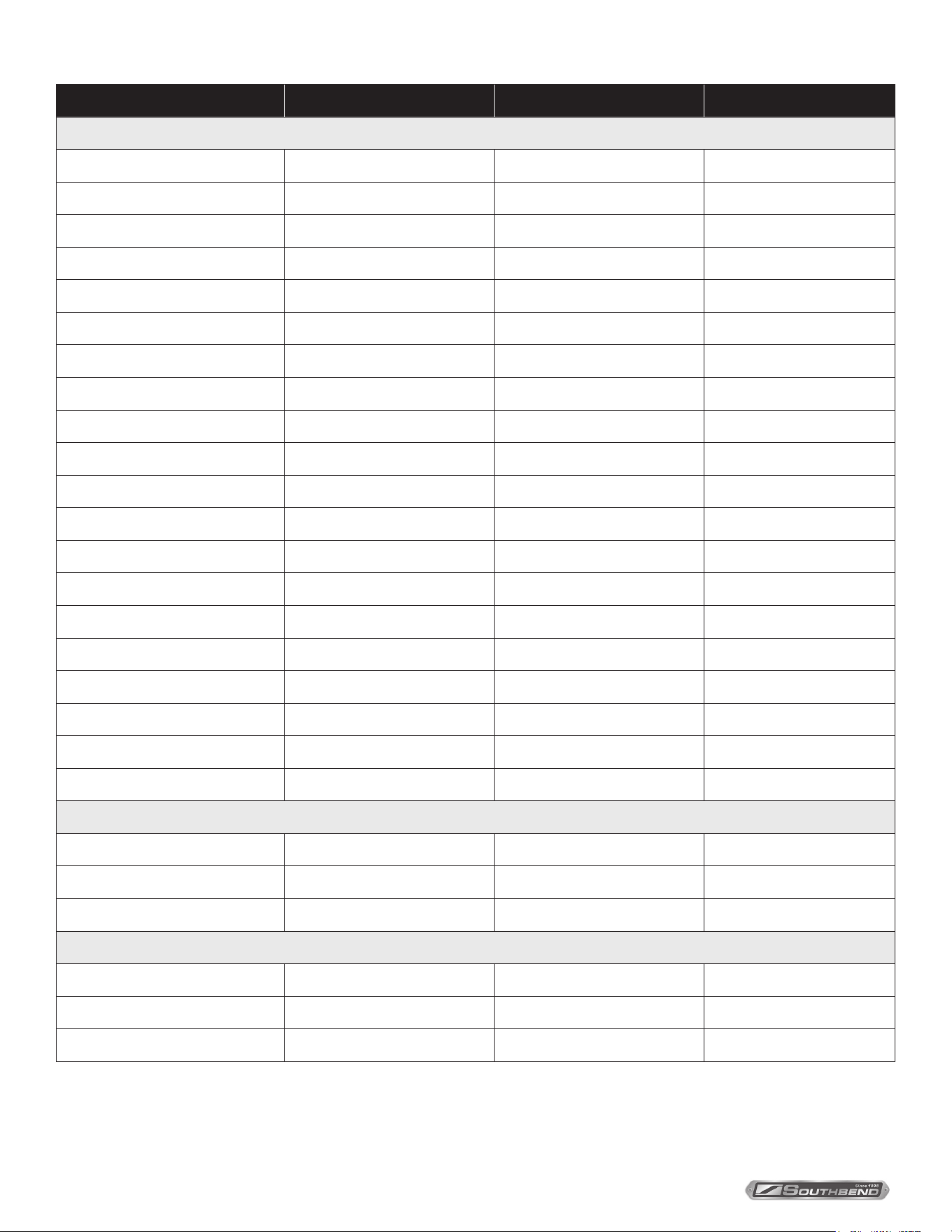
Guide to Times and Temperatures
As a guide, set oven temperatures 25°F to 75°F lower than called for in recipes for non-convection ovens, (i.e., range or
deck ovens).
Time and temperature will vary depending upon load, mix, size, portion, initial temperature of food, and other factors.
Use the following chart as a starting point to develop your own cooking techniques. Rack loading and position may aect
results. Experimentation may be necessary to suit individual requirements.
Product Cooking Time Temperature Number of Racks
Meat and Fish
Top Round, 18-20 lbs. (medium) 5 hours 225°F 1
Prime Ribs (rare) 4 hours 225°F 1
Burger Patties, 4 oz. 5 min. 350°F 3
Fish Cakes 10-12 min. 350°F 3
Turkey, 10-12 lbs. 3 hours 225°F 1
INSTALLATION & OPERATION MANUAL 1194659-ENGLISH, ELEC, REV 1 (11/21)
PAGE
22
OF 36
TruVection Electric Convection OvensCooking Hints
Product Cooking Time Temperature Number of Racks
Baked Goods
Bread, 2 lb. loaf 35 min. 375°F 2
Biscuits 5-10 min. 350°F 3
Cornbread 18 min. 400°F 3
French Bread 8 min. 375°F 2
Sheet Cake 15-18 min. 300°F 3
Cream Pus 20 min. 325°F 3
Brown & Serve Rolls 5 min. 400°F 3
Ginger Bread 18 min. 300°F 3
Yeast Rolls, sheet pan 14-16 min. 325°F 2
Pineapple Upside Down Cake 25-30 min. 300°F 2
Apple Turnovers 15-18 min. 325°F 3
Fruit Cobbler 20-23 min. 350°F 2
Brownies 15 min. 350°F 3
Danish Pastry 12 min. 325°F 3
Pie Shells 12 min. 350°F 2
Fresh Fruit Pies 25-30 min. 350°F 2
Pumpkin Pies 25-30 min. 275°F 2
Fresh Apple Pies 35 min. 375°F 2
Frozen Berry Pies 40 min. 375°F 2
Frozen Fruit Pies 45 min. 375°F 2
Potatoes
Baked Potatoes, 10 oz. 40-45 min. 450°F 2
Baked Potatoes, 6-8 oz. 30-35 min. 450°F 3
Scalloped Potatoes 28 min. 325°F 3
Miscellaneous
Macaroni and Cheese 25 min. 350°F 2
Stued Peppers 18 min. 350°F 3
Toasted Cheese Sandwiches 8 min. 375°F 3
INSTALLATION & OPERATION MANUAL 1194659-ENGLISH, ELEC, REV 1 (11/21)
PAGE
23
OF 36
TruVection Electric Convection Ovens Cleaning
Cleaning
Southbend equipment is sturdily constructed of the best materials and is designed to provide durable service when treated
with ordinary care. To expect the best performance, your equipment must be maintained in good condition and cleaned
daily. Naturally, the periods for this care and cleaning depend on the amount and degree of usage.
Following daily and periodic maintenance procedures will enhance long life for your equipment. Climatic conditions (such
as salt air) may require more thorough and frequent cleaning or the life of the equipment could be adversely aected.
The oven interior is nished with a porcelain enamel coating. “Spillovers” should be cleaned from the interior bottom
surface as soon as possible to prevent carbonizing and a burnt-on condition. Grease or any residue should be cleaned
from interior surfaces as soon as it accumulates.
WARNING
FOR YOUR SAFETY, DISCONNECT THE POWER SUPPLY TO THE APPLIANCE BEFORE CLEANING.
WHEN CLEANING THE BLOWER WHEEL, BE SURE TO HAVE THE POWER SWITCH IN THE “OFF” POSITION.
Daily Cleaning
1. Turn the power switch to OFF and allow the oven to cool.
2. Remove the oven-interior racks and rack slide frames. (The rack slide frames are readily removable by merely raising
to disengage them from their sockets.) Wash the racks and rack slides in a sink with mild detergent and warm water.
Dry them thoroughly with a clean cloth.
3. Look to see if any foreign matter has accumulated on the blades of the blower wheel (which will reduce air circulation).
If necessary, remove the rear lining of the oven, which is secured by thumbscrews near each corner. Use a sti brush
to remove accumulations from the blower blades, then wash with soap and water.
4. Wash the interior surfaces with mild detergent and warm water. Rinse with clean water, and dry thoroughly with a
clean cloth. For stubborn accumulations, a commercial oven cleaner may be used.
5. Clean the control panel with warm water and mild soap. Never use cleaning solvents with a hydrocarbon base.
6. Wipe the other exterior surfaces with a clean damp cloth. If the exterior surfaces require more thorough cleaning, see
“Cleaning Stainless Steel Surfaces” on the next page.
7. Return the rack slides and racks to their appropriate locations inside the oven.
8. LEAVE THE DOOR OPEN AT NIGHT AFTER CLEANING. This allows the oven to dry thoroughly after cleaning and
also prolongs the life of the door gasket.
Monthly Cleaning
Clean around rear of motor (where the vent screen is located), louvered panels, and air holes in the rear of the oven
where grease or lint may have accumulated.

INSTALLATION & OPERATION MANUAL 1194659-ENGLISH, ELEC, REV 1 (11/21)
PAGE
24
OF 36
TruVection Electric Convection Ovens
Semiannual Cleaning
At least twice a year have your Southbend Authorized Service Agency or another qualied service technician clean and
adjust the unit for maximum performance.
At least twice a year the oven’s venting system should be examined and cleaned.
Cleaning Stainless Steel Surfaces
To remove normal dirt, grease and product residue from stainless steel that operates at LOW temperature, use ordinary
soap and water (with or without detergent) applied with a sponge or cloth. Dry thoroughly with a clean cloth.
To remove grease and food splatter, or condensed vapors, that have BAKED on the equipment, apply cleanser to a damp
cloth or sponge and rub cleanser on the metal in the direction of the polishing lines on the metal. Rubbing cleanser, as
gently as possible, in the direction of the polished lines will not mar the nish of the stainless steel. NEVER RUB WITH A
CIRCULAR MOTION. Soil and burnt deposits which do not respond to the above procedure can usually be removed by
rubbing the surface with SCOTCH-BRITE scouring pads or STAINLESS scouring pads. DO NOT USE ORDINARY STEEL
WOOL, as any particles left on the surface will rust and further spoil the appearance of the nish. NEVER USE A WIRE
BRUSH, STEEL SCOURING PADS (EXCEPT STAINLESS), SCRAPER, FILE OR OTHER STEEL TOOLS. Surfaces
which are marred collect dirt more rapidly and become more dicult to clean. Marring also increases the possibility of
corrosive attack. Renishing may then be required.
To remove heat tint – Darkened areas sometimes appear on stainless steel surfaces where the area has been subjected
to excessive heat. These darkened areas are caused by thickening of the protective surface of the stainless steel and are
not harmful. Heat tint can normally be removed by the foregoing, but tint which does not respond to this procedure calls
for a vigorous scouring in the direction of the polish lines, using SCOTCH-BRITE scouring pads or a STAINLESS scouring
pad in combination with a powered cleanser. Heat tint action may be lessened by not applying, or by reducing heat to
equipment during slack periods.
Cleaning
INSTALLATION & OPERATION MANUAL 1194659-ENGLISH, ELEC, REV 1 (11/21)
PAGE
25
OF 36
TruVection Electric Convection Ovens Adjustments
Lubrication
The door chains and sprockets have been lubricated at the factory with high temperature “Never Seeze” lubricant. After
each six months of usage, lubricate the door chains and sprockets with the same type of lubricant.
Motor lubrication information can be found on permanent label located on motor.
Adjusting Door Chain Mechanism
The door chain mechanism causes the left and right doors to open and close together. To adjust the door chain
mechanism, do the following:
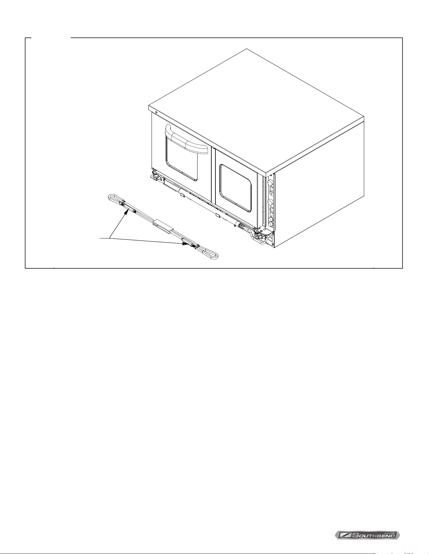
1. Remove lower front panel that covers the door chain mechanism (shown below).
2. Close both doors.
3. Check the positioning of the chain on the sprockets. There should be ve regular links and one master link visible on
the front side of each chain. If not, open the turnbuckles and reposition the chain over the sprockets.
4. Adjust the turnbuckles so that the right door closes about 1/4” to 1/2” inch ahead of the left door. The left door should
be pushed tight over the friction catch so both doors are completely closed against the frame.
5. Secure the turnbuckles by tightening their locknuts.
WARNING
ADJUSTMENTS AND SERVICE WORK MAY BE PERFORMED ONLY BY A QUALIFIED TECHNICIAN WHO
IS EXPERIENCED IN, AND KNOWLEDGEABLE WITH, THE OPERATION OF COMMERCIAL COOKING
EQUIPMENT. HOWEVER, TO ASSURE YOUR CONFIDENCE, CONTACT YOUR AUTHORIZED SERVICE
AGENCY FOR RELIABLE SERVICE, DEPENDABLE ADVICE OR OTHER ASSISTANCE, AND FOR GENUINE
FACTORY PARTS.
NOTICE
Warranty will be void and the manufacturer is relieved of all liability if service work is performed by other
than a qualified technician, or if other than genuine Southbend replacement parts are installed.
Adjustments
INSTALLATION & OPERATION MANUAL 1194659-ENGLISH, ELEC, REV 1 (11/21)
PAGE
26
OF 36
TruVection Electric Convection OvensAdjustments
Turnbuckles
Door Chain Adjustment
FIGURE 14
Temperature Controller
The calibration of the temperature controller should not be changed until sucient experience with cooking results has
denitely proved that the temperature controller is not maintaining proper oven temperatures. Before any recalibration is
attempted, the oven temperature should be checked by the following procedure:
1. Remove all trays and pans from the oven.
2. Place a thermocouple or a reliable mercury oven-type thermometer at the center of the middle rack.
3. Turn the oven ON and set the temperature control knob to 400°F.
4. The amber “heat on” light will go out when the oven temperature is reached.
5. Allow three cycles for the temperature to stabilize.
6. Read the thermocouple or thermometer immediately after the light goes out for the third time, and again immediately
after it comes on the next time.
7. If the average of these readings varies by more than 10°F from the dial setting, recalibrate by the following procedure.
Recalibration should be attempted only by a competent service technician.
Use the following procedure to recalibrate the oven:
1. Loosen the two set screws that secure the temperature-control knob to the temperature-control shaft.
2. Remove the knob from the shaft, being careful not to rotate the knob or shaft.
3. Replace the knob on the shaft so that the indicator mark on the knob points directly at the temperature that was
measured at the center of the oven.
4. Re-check the oven calibration.
INSTALLATION & OPERATION MANUAL 1194659-ENGLISH, ELEC, REV 1 (11/21)
PAGE
27
OF 36
TruVection Electric Convection Ovens Adjustments
Conversion from Single-Phase to Three-Phase power (or vice versa)
Ovens are shipped wired for either single-phase or three-phase power according to the original factory order. If the oven
installation requires changing the type of power used by the oven, follow the procedure below. The following drawing
shows the locations of items referred to in the procedure.
FIGURE 15
1. If the oven is connected to a power supply, DISCONNECT OVEN FROM POWER SUPPLY.
2. Remove the element-cover box from the back of the oven. (An oven built for three-phase power will have a small
jumper wire attached with the element box cover to the back of the oven. Keep this wire.)
3. Locate and remove the four screws that secure the lower front panel (items “A” in the drawing above). Lift up the
panel and pull it forward to remove it, then set it aside.
4. Locate and remove the two now-accessible screws that secure the lower front corner of the side panel.
5. Locate and remove the three screws that secure the back edge of the side panel to the oven (items “B” in the drawing
above). Remove the side panel and insulation and set them aside.
6. Locate the wires running from the supply-power terminal block to the contactor. If converting from three-phase to
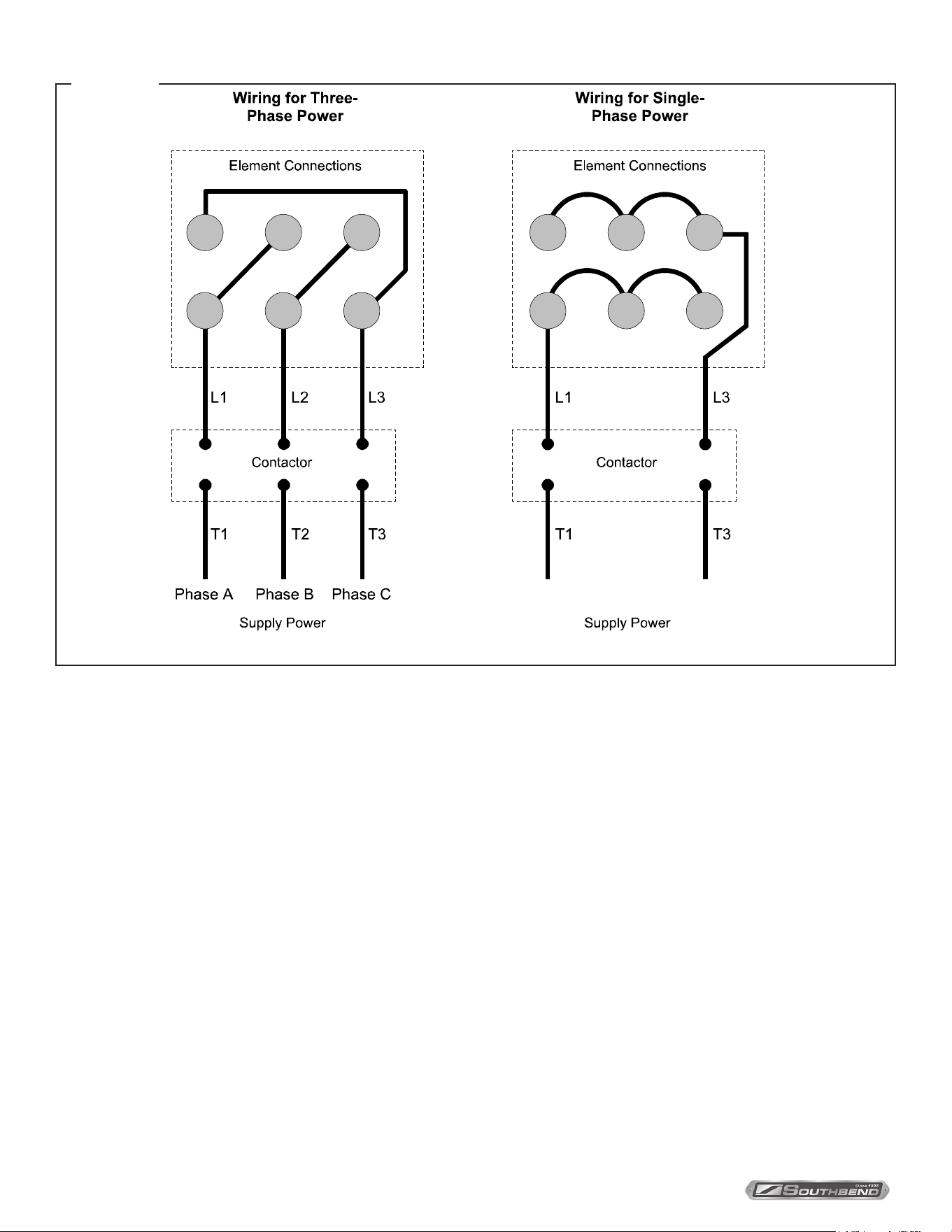
single-phase power, remove the wire T2 (as shown in the following drawing) and go on to the next step. If converting
from single-phase to three-phase power, locate the wires running from the contactor to the elements. Attached to
those wires (with a wire tie) will be two wires that are not being used. Use the shorter of the two extra wires to make
the additional connection (T2) shown in the following drawing. Keep the longer wire to use in the next step. (Note:
If you are changing the phase-wiring of a 415V oven, refer to the corresponding wiring diagram for conversion. See
page 30.)
INSTALLATION & OPERATION MANUAL 1194659-ENGLISH, ELEC, REV 1 (11/21)
PAGE
28
OF 36
TruVection Electric Convection OvensAdjustments
Wiring is different for 415V ovens; refer to corresponding wiring diagram (see page 30).
FIGURE 16
7. Locate the wires running from the contactor to the elements. If converting from three-phase to single-phase power,
remove the wire L2 (as shown in the above drawing) and go on to the next step. If converting from single-phase
to three-phase power, use the longer of the two extra wires found in the previous step to make the additional
connection (L2) shown in the above drawing. (Again, if you are changing the phase-wiring of a 415V oven, refer to the
corresponding wiring diagram for conversion. See page 30.)
8. Rewire the connections to the elements (located on the back of the oven) according to the diagram at the top of
this page. If converting from three-phase to single-phase, use the wire that you saved in Step 2 to make one of the
connections. (Once more, if you are changing the phase-wiring of a 415V oven, refer to the corresponding wiring
diagram for conversion. See page 30.)
9. Carefully compare the new wiring connections at the elements, contactor, and supply-power terminal block to the
wiring diagram for the oven. (See page 30 for the location of the wiring diagram on the oven, or page 30 for wiring
diagrams printed in this manual). Verify that all connections are tight.
10. Reattach the element-cover box, right-side panel, and lower-front panel.
11. Connect the oven to the power supply according to the procedure on page 15. Note that the supply-power
connections depend on whether the supply power is three-phase or single phase, and so will be dierent than they
were prior to the conversion.
12. Double-check supply-wire sizing for new amperage load (see page 4).
INSTALLATION & OPERATION MANUAL 1194659-ENGLISH, ELEC, REV 1 (11/21)
PAGE
29
OF 36
TruVection Electric Convection Ovens Troubleshooting
When any diculty arises it is always a good idea to check that the oven has been connected to the type of voltage for
which it was manufactured. The serial plate is located on the inside of the lower front panel. It will list the type of voltage
for which the unit was manufactured. In addition, a wiring diagram is attached to the side of the slide-out control panel, as
well as reproduced in this manual (see page 30).
Troubleshooting Guide
The left column of the following table lists symptoms that indicate a problem, while the center and right columns list the
possible causes and appropriate corrective action. Note that the recommendations of this table assume that the wiring
connections are good. When checking a component, always check the wiring attached to the component as well.
Symptom Possible Cause Check or Replace
Oven will not hold correct temperature. Temperature probe not working. Resistance across temperature probe leads
at room temperature (70°F) should be
approximately 1096 ohms.
Temperature control not calling for heat. When heat is required, there should be
continuity between terminals 6 and 7 on
temperature control.
Inadequate or improper ventilation. Check ventilation hood. Verify draw and make
up air adjustment.
Out of calibration. Calibrate according to procedure described on
page 26.
Bad contactor. Verify that contactor is pulling in and supplying
power to the elements.
Blower motor will not come on. No incoming electric power. Check incoming power and fuses.
Loose wire connections. Check wire connections.
Motor bad. If power is being supplied but motor will not turn,
replace motor.
Shut down switch bad. All power except for element supply comes
through the shut down switch. Check for
continuity.
Power switch bad. All power except for element supply comes
through the power switch. Check for continuity.
Troubleshooting
WARNING
ADJUSTMENTS AND SERVICE WORK MAY BE PERFORMED ONLY BY A QUALIFIED TECHNICIAN WHO
IS EXPERIENCED IN, AND KNOWLEDGEABLE WITH, THE OPERATION OF COMMERCIAL COOKING
EQUIPMENT. HOWEVER, TO ASSURE YOUR CONFIDENCE, CONTACT YOUR AUTHORIZED SERVICE
AGENCY FOR RELIABLE SERVICE, DEPENDABLE ADVICE OR OTHER ASSISTANCE, AND FOR GENUINE
FACTORY PARTS.
NOTICE
Warranty will be void and the manufacturer is relieved of all liability if service work is performed by other
than a qualified technician, or if other than genuine Southbend replacement parts are installed.
INSTALLATION & OPERATION MANUAL 1194659-ENGLISH, ELEC, REV 1 (11/21)
PAGE
30
OF 36
TruVection Electric Convection Ovens
Control Panel Access and Shut-Off Switch
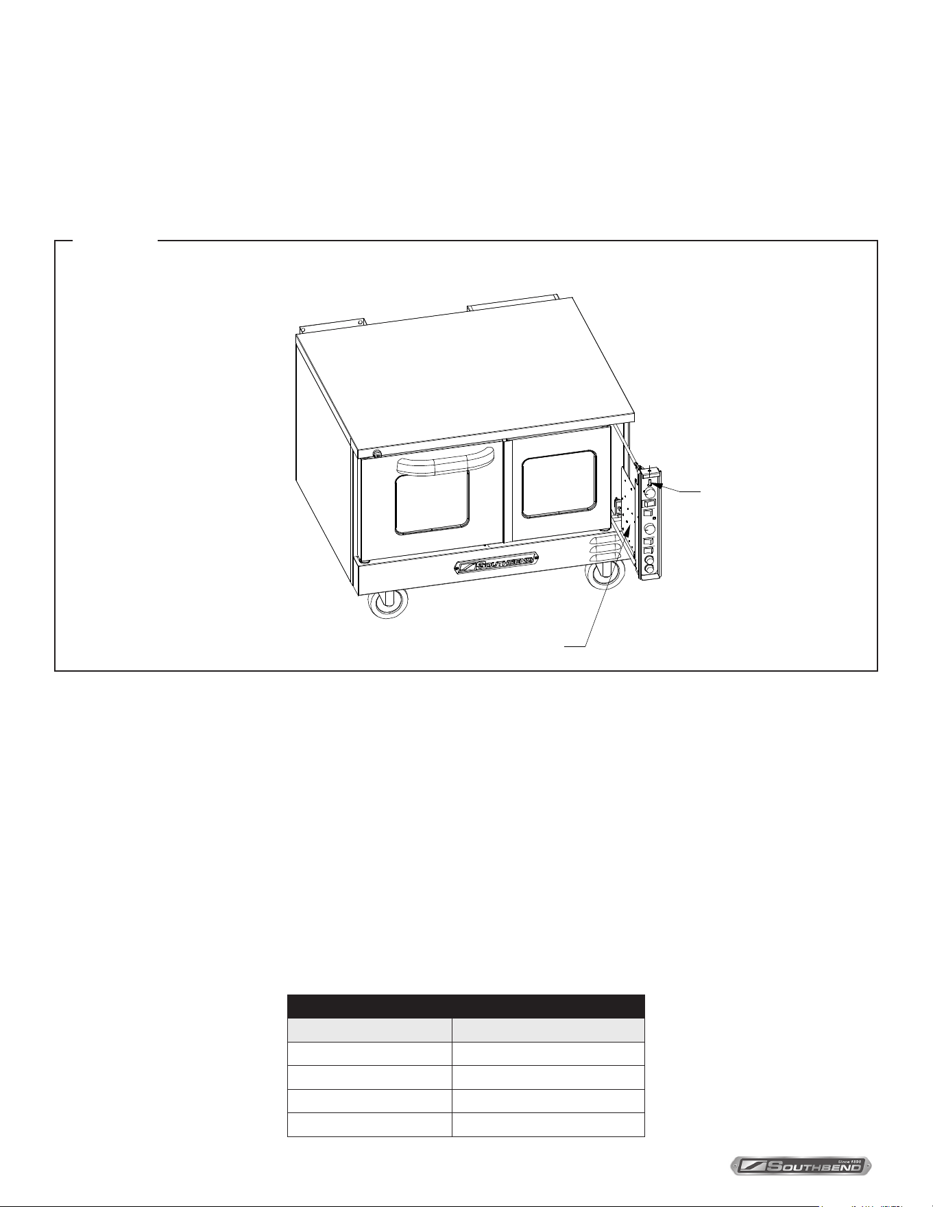
To access the control panel components, remove the screw at the top of the control panel and pull the top of the control
panel out (see drawing below). A wiring diagram for the oven is located on the side of the control panel assembly. When
the control panel is slid out, all power to the control panel is cut o by a shut down switch that is located directly behind
and below the control panel. To re-energize the controls for troubleshooting, pull the white plunger on the shut down
switch forward.
Troubleshooting
Screw
Location of Wiring Diagram
Accessing Control Panel Components
FIGURE 17
Blower Wheel Replacement
To replace the blower wheel, do the following:
1. Remove racks and rack guides.
2. Remove rear air bae in front of blower wheel.
3. Loosen the two square heads on blower wheel hub.
4. Pull blower wheel from motor shaft. If blower wheel is dicult to pull o, use puller disk (available from Southbend as
part number 1179100).
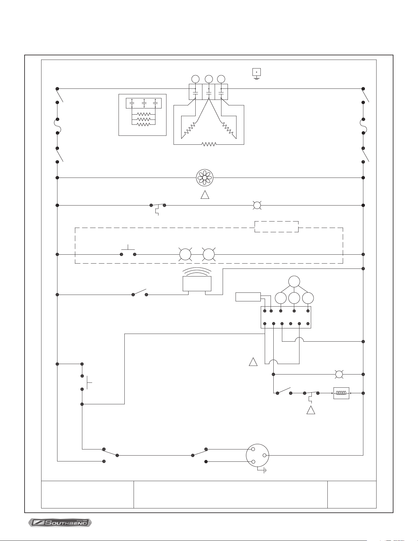
Wiring Diagrams
A wiring diagram is located on the side of the control panel assembly (as shown on page 30). Wiring diagrams also
appear on the following pages of this manual. Which wiring diagram is appropriate depends on the voltage.
Index of Wiring Diagrams
Page Number Description
31 208/240 Volt Models
32 380 Volt Models
33 480 Volt Models
34 415 Volt WYE Models
INSTALLATION & OPERATION MANUAL 1194659-ENGLISH, ELEC, REV 1 (11/21)
PAGE
31
OF 36
TruVection Electric Convection Ovens Troubleshooting
Wiring Diagram for 208/240 Volt Models
SWITCH
POWER
PROBE
SWITCH
CENTRIFUGAL
SCHEMATIC, TRUVECTION
COOL
WIRING DIAGRAM
FAN SWITCH
COOK
SOUTHBEND
208/240V ELEC
FAN SPEED
LOW
HI
SWITCH
DOOR
TIMER
BUZZER
SWITCH
LIGHT
SWITCH
SHUTDOWN
LIGHTS
GND
M
1194585
PART NO:
POTENTIOMETER
Y
3
6 7 8 9 10 11
5 4
P
V
2
O
1
CONTROL BOARD
TEMPERATURE
OPTIONAL
NOTE:
ELEMENTS ARE 2500 WATTS EACH
FUSE
SWITCH
POWER
FUSE
SHUTDOWN
SWITCH
HEAT
INDICATOR
LIMIT
HIGH
A
CONTROLS FAN
LIMIT
CONTROLS
WARNING
INDICATOR
B
C
3 PHASE
L1
CONTACTOR
L2 L3
1 PHASE
COIL
CONTACTOR
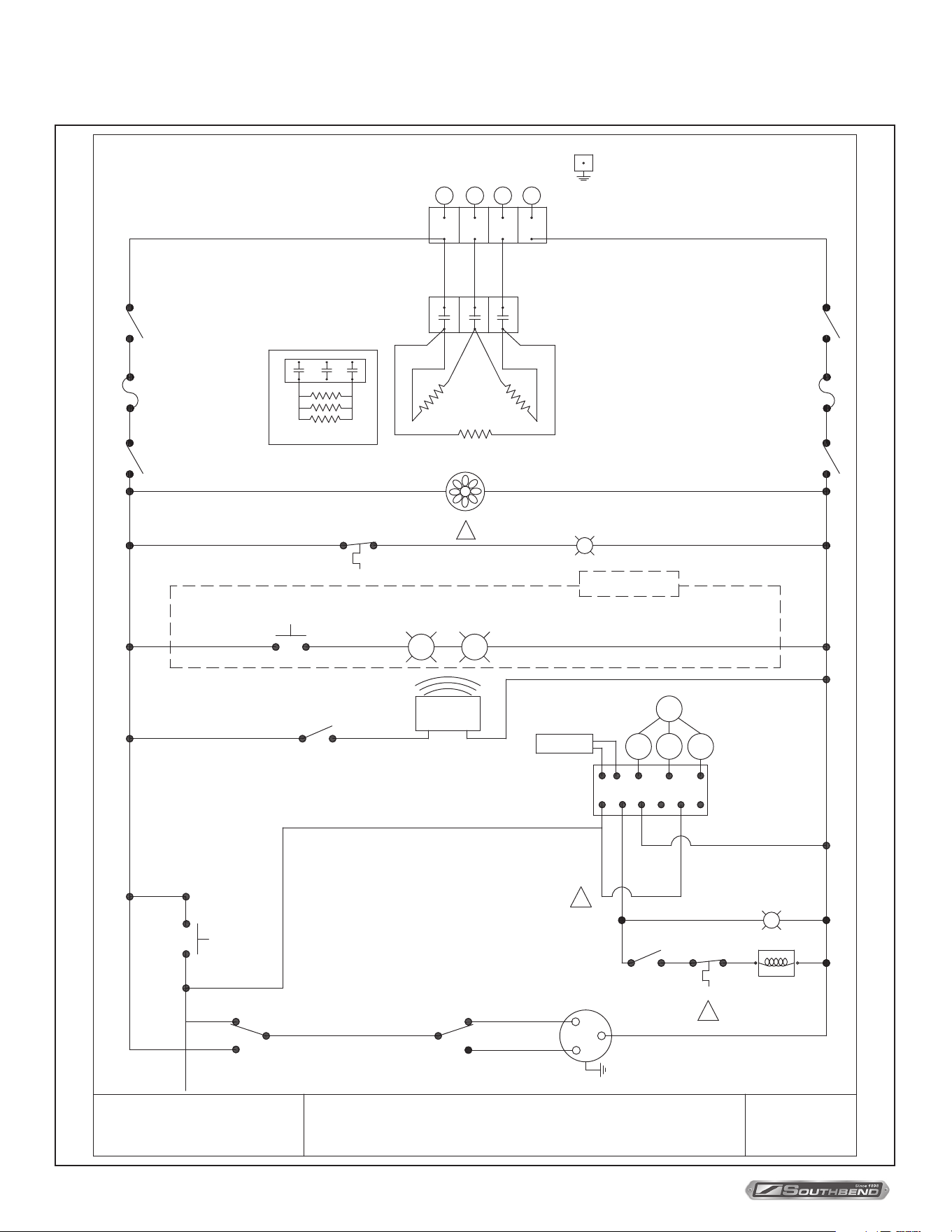
INSTALLATION & OPERATION MANUAL 1194659-ENGLISH, ELEC, REV 1 (11/21)
PAGE
32
OF 36
TruVection Electric Convection OvensTroubleshooting
Wiring Diagram for 380 Volt Models
SWITCH
POWER
PROBE
SCHEMATIC, TRUVECTION
COOL
WIRING DIAGRAM
FAN SWITCH
COOK
SOUTHBEND
380V ELEC
FAN SPEED
LOW
HI
SWITCH
DOOR
TIMER
BUZZER
SWITCH
LIGHT
SWITCH
SHUTDOWN
LIGHTS
GND
M
1195245
PART NO:
POTENTIOMETER
Y
3
6 7 8 9 10 11
5 4
P
V
2
O
1
CONTROL BOARD
TEMPERATURE
OPTIONAL
NOTE:
ELEMENTS ARE 2500 WATTS EACH
FUSE
SWITCH
POWER
FUSE
SHUTDOWN
SWITCH
CENTRIFUGAL
SWITCH
LIMIT
HIGH
HEAT
INDICATOR
A
CONTROLS
CONTROLS FAN
LIMIT
B
WARNING
INDICATOR
C
3 PHASE
CONTACTOR
1 PHASE
L1 L3L2 N
TERMINAL
BLOCK
COIL
CONTACTOR
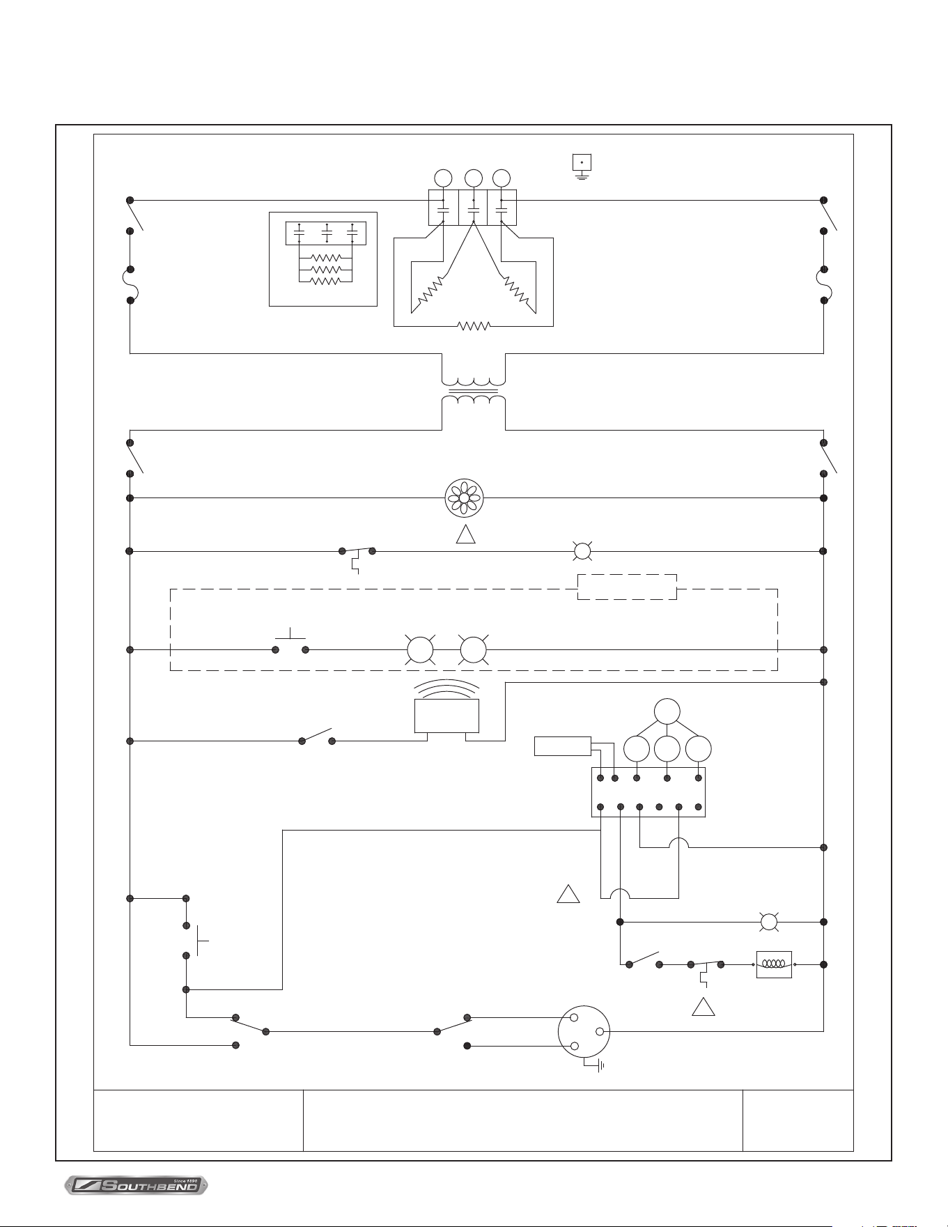
INSTALLATION & OPERATION MANUAL 1194659-ENGLISH, ELEC, REV 1 (11/21)
PAGE
33
OF 36
TruVection Electric Convection Ovens Troubleshooting
Wiring Diagram for 480 Volt Models
SWITCH
POWER
PROBE
SCHEMATIC, TRUVECTION
COOL
WIRING DIAGRAM
FAN SWITCH
COOK
SOUTHBEND
480V ELEC
FAN SPEED
LOW
HI
SWITCH
DOOR
TIMER
BUZZER
SWITCH
LIGHT
SWITCH
SHUTDOWN
LIGHTS
GND
M
1194586
PART NO:
POTENTIOMETER
Y
3
6 7 8 9 10 11
5 4
P
V
2
O
1
CONTROL BOARD
TEMPERATURE
OPTIONAL
NOTE:
ELEMENTS ARE 2500 WATTS EACH
FUSE
SWITCH
POWER
FUSE
SHUTDOWN
SWITCH
TRANSFORMER
240V
480V
CENTRIFUGAL
SWITCH
LIMIT
HIGH
HEAT
INDICATOR
B
CONTROLS
CONTROLS FAN
LIMIT
C
WARNING
INDICATOR
D
3 PHASE
L1
CONTACTOR
L2 L3
1 PHASE
COIL
CONTACTOR
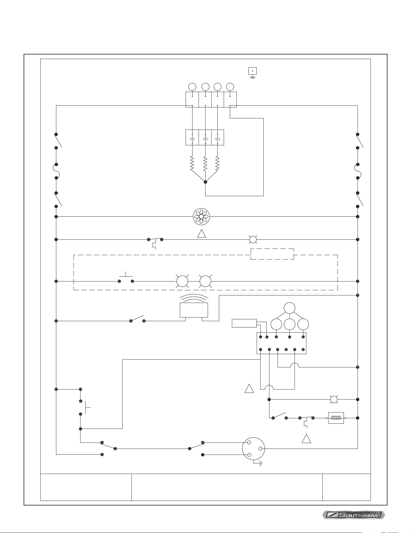
INSTALLATION & OPERATION MANUAL 1194659-ENGLISH, ELEC, REV 1 (11/21)
PAGE
34
OF 36
TruVection Electric Convection OvensTroubleshooting
Wiring Diagram for 415 Volt Wye Models
SWITCH
POWER
PROBE
SCHEMATIC, TRUVECTION
COOL
WIRING DIAGRAM
FAN SWITCH
COOK
SOUTHBEND
415V WYE ELEC
FAN SPEED
LOW
HI
SWITCH
DOOR
TIMER
BUZZER
SWITCH
LIGHT
SWITCH
SHUTDOWN
LIGHTS
GND
M
1195368
PART NO:
POTENTIOMETER
Y
3
6 7 8 9 10 11
5 4
P
V
2
O
1
CONTROL BOARD
TEMPERATURE
OPTIONAL
NOTE:
ELEMENTS ARE 2500 WATTS EACH
FUSE
SWITCH
POWER
FUSE
SHUTDOWN
SWITCH
CENTRIFUGAL
SWITCH
LIMIT
HIGH
HEAT
INDICATOR
A
CONTROLS
CONTROLS FAN
LIMIT
B
WARNING
INDICATOR
C
3 PHASE
CONTACTOR
L1 L2 L3
TERMINAL BLOCK
N
ELEMENTS
COIL
CONTACTOR

INSTALLATION & OPERATION MANUAL 1194659-ENGLISH, ELEC, REV 1 (11/21)
PAGE
35
OF 36
TruVection Electric Convection Ovens Notes
Notes
INSTALLATION & OPERATION MANUAL 1194659-ENGLISH, ELEC, REV 1 (11/21)
PAGE
36
OF 36
TruVection Electric Convection Ovens
TVES/10SC, TVES/20SC & TVES/30SC
TruVection
Electric Convection Ovens
A product with the Southbend name incorporates the best in durability and low maintenance. We all recognize, however,
that replacement parts and occasional professional service may be necessary to extend the useful life of this appliance.
When service is needed, contact a Southbend Authorized Service Agency, or your dealer. To avoid confusion, always
refer to the model number, serial number, and type of your appliance.
SOUTHBEND
A Middleby Company
1100 Old Honeycutt Road Fuquay-Varina, North Carolina 27526 USA
www.southbendnc.com

