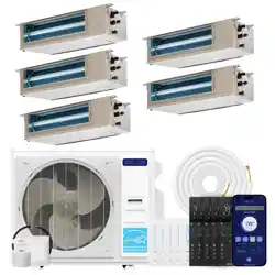
Concealed Duct Series
Instruction Manual
Installation and Operation Guide
Watch video
before Installation
Welcome to
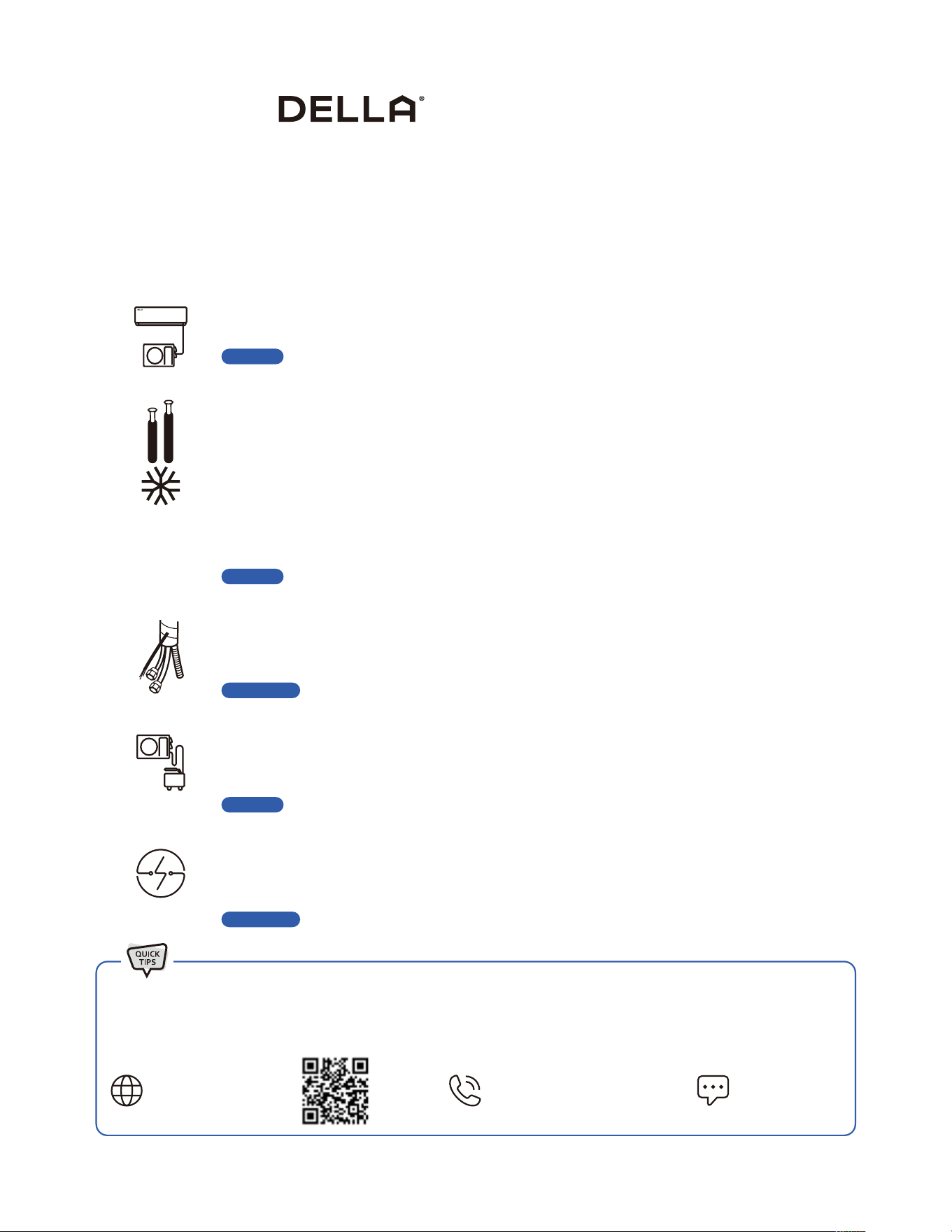
5 Things to know before installation
The installation location is critical
Handle the refrigerant pipes perfectly
Arrange and insulate the line set correctly
Vacuum pumping the refrigerant circuit
Safe electrical connection
Not all places are created equal. Only proper placement of the AC will maximize ecency while balancing the interior
aesthetic. You need to make sure to get the placement and location right the rst time.
-14-
Thank You for trusting Della as your home comfort solution. We know no better how exicting it must be to have a new and functional AC to make
your living space more comfortable. But AC installation, in reality, is far from being simple. Here are a few things you must know before installing
the AC whether by yourself or by a professional HVAC technician. This will give you an idea of what to look out for installing an AC so that it can
perform at its maximum eciency and every dollar you invest in it pays o.
The refrigerant pipe is one of the most important, if not the most important, parts of the mini split AC system. So, be
sure to understand what the entire process entails. You might need special-purpose tools to shorten and bend the
pipe. Purchaseing lengthening pipes to match your connection might also be necessary. Any ow in the handling of the
refrigerant pipes may cause a refrigerant leak or reduced eciency. The cost to repair or re-install the refrigerant pipe
can quickly frustrate and upset any DIYer, especially when trying to save money by not hiring a professional. Additional
refrigerant might also be needed if you used lengthening pipes or nd any leaks during your install. Further more, it's
always a good idea to test for any refrigerant leaks after completing your installation by using soapy spray or professional
detector tools. Please contact us if you need extra refrigerant.
-22-
The line set contains the refrigerant pipes, drain hose, and electrical wires. A good arrangment and insulation prevent
water condensation and protects it from extermal elements, as well as matching the exact distance of the installation. No
one wants extra line set dangling around.
-18, 30-
AC absolutely needs vacuum pumping in order to perform ecently and prevent refrigerant from reacting with air
moisture and damaing the internal parts of the machine. With a vacuum pump and a micron gauge, the process does not
take very long, but it is important to do it right.
-26-
A safe and properly electrical connection is crucial necessity for the installation. The voltage, power breaker protection,
cable requirement and wiring must correspond to the specications of each model. A poor connection can quickly
becomes a re hazard.
-12, 25-
Page 14
Page 25
Page 36
Page 22, 28
Page 23, 33
Most of the problems emerge from incorrect or poor installation. Installation performed by professional HVAC technician can greatly
reduce the chance of having problems for years to come. On top of that, Della provide extended warranty for professional installation.
If you need assistance or have questions, we are here for you.
support.dellahome.com
24/7 Live Chat
800-863-4143
6:00 a.m. - 4:00 p.m. PST
Monday - Friday

Table of Content
Warning and Safety
Name of Parts
Product Specication
04
09
11
75
76
72
73
74
77
83
84
Air Filter
Maintenance Routine
Wi- Set Up
Refrigerant Sensor
Operation Temperature
Installation Preview
Installation Info
Indoor Unit Installation
Outdoor Unit Installation
Circuit Diagram
Vacuum Pumping
Thermostat Installation
Check List
Test Run
12
13
15
29
34
36
40
44
45
Troubleshooting
Disposal Guideline
Warranty
Power ON / OFF
Operation Modes
- Auto, Cool, Heat, Dry, Fan
Change Temperature
Change Fan Speed
Power ON / OFF
Operation Modes
- Auto, Cool, Heat, Dry, Fan
Change Temperature
Change Fan Speed
52
52
52
53
53
62
62
62
62
62
Turbo Mode
Quiet Mode
Eco Mode
Sleep Mode
Timer
Vicinity Sensor
Self Cleaning
Child Lock
°F / °C
Force Defrost
Sleep Mode
Eco Mode
Self Cleaning
8 Degree Heating
Child Lock
Parameter Setting
Timer Setting
Real Time Timer
Wi- Reset
54
54
55
55
56
57
58
58
59
59
63
63
63
64
64
65
66
69
69
Operation Tips 46
Before Installation
Care and Maintenance
Having Problems?
Installation
Before Using
Remote Control
Thermostat
Other Function
Basic Operation
Basic Operation
Advance Function
Advance Function
4
Before Installation
Warning and Safety
• Read this guide before installation. Failure to follow the safety instructions may result in property damage, serious injury, or death.
• Please Keep this manual.
Danger:
Indicates an IMMINENTLY hazardous situation that, if not avoided, will result in death, serious injury, or serious property damage.
Warning:
Indicates an POTENTIALLY hazardous situation that, if not avoided, will result in death, serious injury, or serious property damage.
Caution:
Indicates an POTENTIALLY hazardous situation that, if not avoided, will result in minor to moderate injury. It may also be used to
indicate unsafe practice.
About Refrigerant
Attention:
Pay additional attention to the instruction.
DO NOT:
Indicates prohibited actions and / or practice.
• The air conditioner is pre-charged with refrigerant. Handle the air conditioner with care and check if there is any
refrigerant leakage during installation. Refrigerants have no odor and can be toxic and ammable. Rapid evaporation of
refrigerant may cause frostbite, cardiac arrhythmia, and / or irritation, as well as cause environmental damage.
• In the case of refrigerant leakage, shut down the appliance and disconnect from the power supply. An inspection must
be performed by a qualied technician.
DANGER
DANGER
WARNING
CAUTION
• In UL/CSA 60335-2-40, R454B refrigerant is classied as class A2L, which is mildly ammable. Therefore, R454B
refrigerant is suitable for system needing additional refrigerant charge and which will limit the area of the rooms being
served by the system. Similarly, the total amount of refrigerant in the system shall be less than or equal to the allowable
maximum refrigerant charge. The allowable maximum refrigerant charge depends on the area of the rooms being
served by the system.
• For R454B refrigerant, the maximum charge in a room shall be in accordance with the following:
• M = Mass
• M
max = Maximum charge mass
• Mc = Mass charged
• A = Floor area
• LFL = Lower Flammable Limit, for R454B LFL is 0.296 kg / m3
• or the minimum oor area A
min to install an appliance with refrigerange Mc (kg) shall be in accordance with:
• M
max = SF x LFL x h0 x A
• A
min = Mc / (SF x LFL x h0)
Additional Information About R454B Refrigerant
WARNING
5
v.20251124U
Before Installation
Warning and Safety
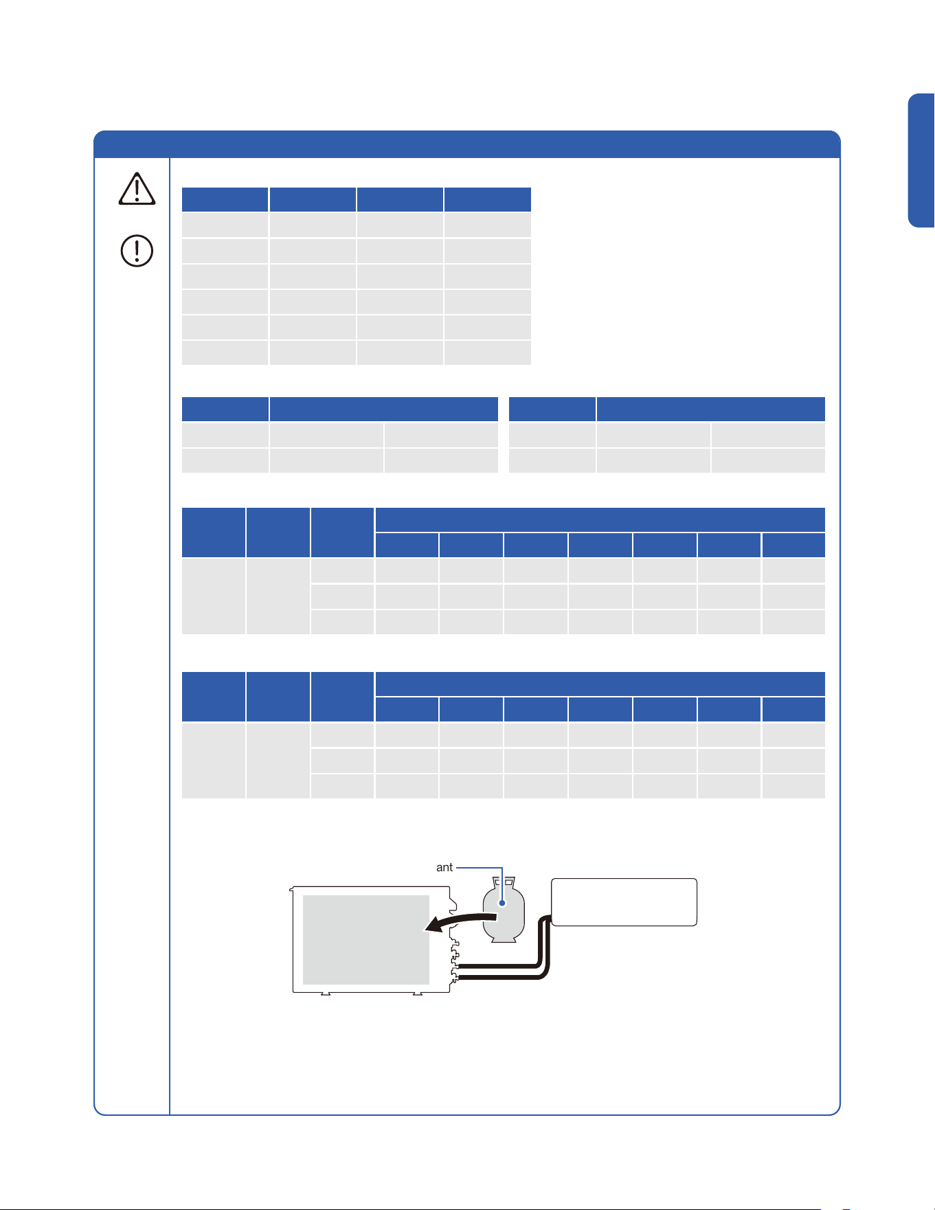
• The minimum opening area for connected rooms. Mc = 1.73kg as an example.
• When the unit detects a refrigerant leak, the minimum airow of the indoor unit is as follows:
Additional Information About R454B Refrigerant
WARNING
A (m²) Mc (kg) Mmax (kg) Anvmin (m²)
4 1.73 1.48 0.0058
7 1.73 2.59 0.0000
10 1.73 3.70 0.0000
15 1.73 5.55 0.0000
20 1.73 7.4 0.0000
30 1.73 11.1 0.0000
Model Minimum Airow
9K 65 CFM 110 m³/h
12K 135 CFM 230 m³/h
Model Minimum Airow
18K 224 CFM 380 m³/h
23K 265 CFM 450 m³/h
Pre-charged
Refrigerant
Pre-charge Refrigerant + Addition Refrigerant
= Total Refrigerant Amount
Additional Refrigerant
• Maximum Charge (kg)
• Minimum Room Area (m2)
Refrigerant
LFL
(kg/m3)
h0 (m)
Floor Area (m2)
4 7 10 15 20 25 30
R454B 0.296
1.8 1.10 1.90 2.70 3.80 4.40 4.90 5.40
2.5 1.48 2.59 3.70 5.55 7.40 9.25 11.10
2.8 1.66 2.90 4.14 6.22 8.29 10.36 12.43
Refrigerant
LFL
(kg/m3)
h0 (m)
Charge Amount (M)
0.8 kg 1 kg 1.2 kg 1.4 kg 1.6 kg 1.8 kg 2.0 kg
R454B 0.296
1.8 3.00 3.75 4.50 5.26 6.01 6.76 7.51
2.5 2.16 2.70 3.24 3.78 4.32 4.86 5.41
2.8 1.93 2.41 2.90 3.38 3.86 4.34 4.83
• The total refrigerant charge should be calculated by adding the precharge amount and additional amount.
6
Before Installation
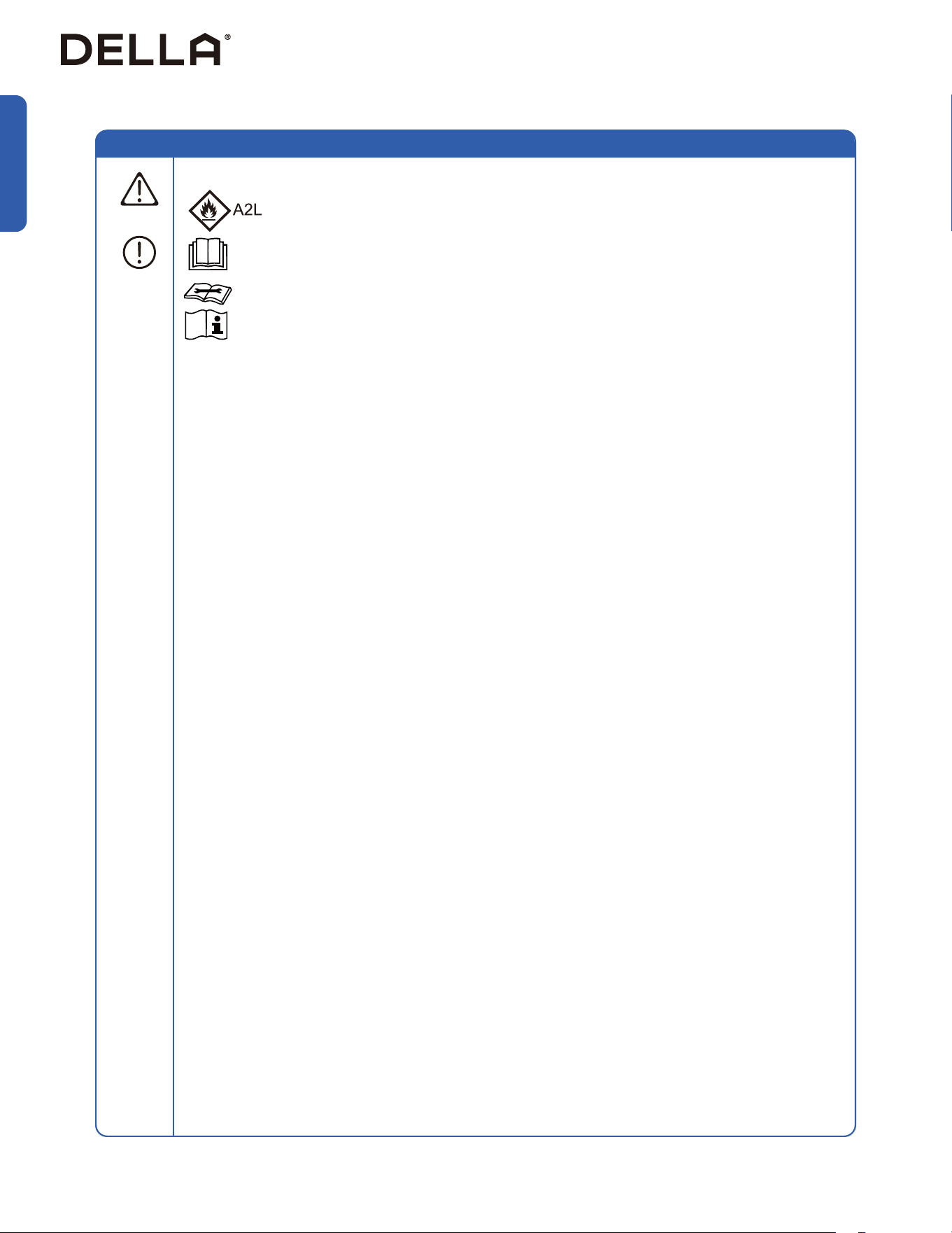
• When Installing or using the appliance with R454B refrigerant, beware of the following symbols.
• This symbol means this appliance uses a ammable rergerant.
If the refrigerant is leaded and exposed to an external ignition source, there is a rist of re.
• This symbol means that read the operation insturction carefully.
• This symbol means that personnel handling the equipment should reference to the installation manual.
• This symbol means information is available in the installation or operation instruction manual.
Warning and Safety
• Prior to any work on systems containing ammable refrigerants, always check the area to ensure that the risk of
ignition is minimized. All possible ignition sources, such as cigarette, should be kept siciently far away from the site
of installation, repairing, removing, and disposal during which refrigerant can possibly be released to the surrounding
space. Prior to work taking place, the area around the equipment should be surveyed to make sure that there are no
ammable hazards or ignition risk. "No smoking" sign shall be displayed.
• Installation or maintenance of refrigerant system shall be taken under a controlled procedure to minimize the risk of
ammable gas or vapor being present while the work is being performed.
• All working personnal and others around the working area shall be instructed on the nature of work being carried out.
Work in conned spaces shall be avoided. The area around the workspace shall be sectioned o, and ensure that the
conditions within the area have been made safe.
• The area shall be checked with an appropriate refrigerant detector prior to and during work to ensure the technician is
aware of potentially ammable atmospheres.
• If any hot work is to be conducted on the refrigeration equipment or any associated parts, appropriate re extinguishing
equipment shall be available to hand.
• Ensure that the area is in the open or it is adequately ventilated before breaking into the system or conducting any work
that will product heat. A degree of ventilation shall continue during the period that the work is carried out.
• The folliwing checks shall be applied to installations using ammable refrigerants:
• The refrigerant charge amount is in accordance with the room size within which the refrigerant containing parts are
installed.
• The ventilation machinery and outlet are operating adequately and are not obstructed.
• If an indirect refrigerating curcuit is being used, the secondary circuit shall be check for the presence of refrigerant.
• Refrigerant pipe or components are installed in a position where they are unlilely to be exposed to any substance
which may corrode refrigerant containing components, unless the components are constructed of materials which
are inherently resistant to being corroded or are suitable protected against being corroded.
• Under no circumstances shall potential sources of ignition be used in the searching for or detection of refrigerant
leaks. A halide torch or any other detector using naked ame shall not be used.
• Electronic leak detectors shall be used to detect ammable refrigerant. Ensure that the detector is not a potential
source of ignition and is suitable for the refrigerant used.
• Leak detection equipment shall be calibrated to the refrigerant employed and the appropriate percentage of gas
(25% maximum) is conrmed.
• Leak detection uids are suitable for use with most refrigerants, but the use of detergents containing chlorine shall
be avoided as chlorine may react with the refrigerant and corrode the pipe work.
• If a leak is suspected, all open ame shall be removed or extinguished.
• If a leakage of refrigerant found which requires brazing, all of the refrigerant shall be recovered from the system, or
isolated (by means of shut o valves) in a part of the system remote from the leak.
• Oxygen free nitogen shall be purged through the system both before and during the brazing process.
• Detection of ammable refrigerants:
Additional Information About R454B Refrigerant
WARNING
7
v.20251124U
Before Installation
• The room for the installation, use, repair, and / or storage of this air conditioner should be greater than 54 sq ft / 5m².
• Stop valve cover must be installed on the air conditioner to prevent possible refrigerant leak.
• Refrigerant leakage or damaged pipelines must be inspected and repaired by a qualied HVAC technician.
• The installation of refrigerant pipe work shall be kept to a minimum length.
• The appliance must be installed in accordance with applicable federal, state, and local regulations.
WARNING
Warning and Safety
About Installation
About Power and Electricity
About Vacuum Pumping
• Do not install or store this appliance in a room with continuously operating ignition sources such as open ames, gas
appliances, or electric heater.
• Do not install the appliance within 20” / 50cm of ammable substances such as alcohol, etc. Or pressurized containers
such as spray cans.
• Do not alter, change, or modify the appliance.
• Do not reuse existing refrigerant line sets when replacing or upgrading an air conditioning system that uses a dierent
refrigerant type. Dierent refrigerants may have dierent chemical properties, lubricants and operate in dierent
pressures, do not assume the existing line set to be compatible.
• Prevent children from accessing the work area during installation to prevent unforeseeable accident.
• The base of the outdoor unit must be rmly xed.
• Carry out a test run after the installation.
• Installation of a mini split AC requires specialized training and equipment. Hire a licensed professional if not familiar with
electrical wiring and HVAC system.
• The packaging materials are recyclable and should be disposed of in a separate waste bins.
• The appliance should not be installed in a location where the air outlet of the indoor or outdoor unit is obstructed.
Obstruction of these opening may cause damage or malfunctions to the appliance.
• Ensure that the power voltage corresponds to that stamped on the rating plate.
• A fuse or overload protection device with a suitable capacity for indoor unit must be installed.
• The appliance must be tted with means for disconnection from the main power supply under
over-voltage category III conditions. All electrical wiring must follow federal, state, or local regulations.
• When working on the electric terminals, ensure the appliance is disconnected from the power supply.
• Make sure the appliance is properly grounded to prevent electric shock.
• All refrigerant lines must be evacuated with an appropriate vacuum pump to remove air and moisture prior to opening
the service valves. Failure to do so may result in system failure, or permanant damage to the appliance and void the
warranty coverage.
• The use of purge kits, canned nitrogen, or refrigerant ushing devices is not an acceptable substitute for proper
evacuation.
• Do not bend, tug, or compress the power cord during installation to prevent damaging the power cord. Damaged
electrical cord should be replaced by a qualied electrician.
• Do not use power extensions and / or multi-socket modules for appliance installation.
WARNING
WARNING
WARNING
CAUTION
8
Before Installation
Warning and Safety
About Handling and Maintenance
Encountering Troubles
• Do not attempt to disassemble, alter, or modify the appliance.
• Do not ush the air conditioner with water.
• Do not attempt to repair, relocate, modify or reinstall the air conditioner by yourself. Incorrect work could cause electric
shocks, re or damage. Contact a qualied technician.
• In the case of the appliance emitting smoke, burning smell, leaking water, or making unusual noise, shut down the
appliance and disconnect from the power supply immediately. Contact a qualied technician for inspection and repair.
• Before cleaning the unit, the appliance must by shut down and disconnect from the power supply for at least 5 minutes.
WARNING
WARNING
WARNING
About Operation
• Do not disconnect the appliance from the power supply before shutting o the appliance. This might create a spark and
potentially cause a re.
• Do not place ammable substances near the appliance.
• Do not climb onto or place any objects on the appliance.
• Do not insert any objects into the appliance to prevent damage or injury.
• Do not obstruct the air inlet or outlet.
• Do not operate the appliance with wet hands.
• If the appliance is used in areas without the possibility of ventilation, precautions must be taken to prevent any leaks of
refrigerant.
• Only use the appliance as instructed in this booklet. These instructions are not intended to cover every possible
condition and situation. As with any electrical household appliance, common sense and caution are therefore always
recommended for usage and maintenance.
• This appliance is designed and made for air conditioning in domestic environments only. It must not be used for any
other purpose such as drying clothes or cooling foods.
• This appliance can be used by children 8 years old or above and persons with reduced physical, sensory, or mental
capabilities, or lack of experience and knowledge if they have been given supervision or instruction concerning the use
of the appliance in a safe way and understand the hazards involved.
• Children shall not play with the appliance.
WARNING
CAUTION
9
v.20251124U
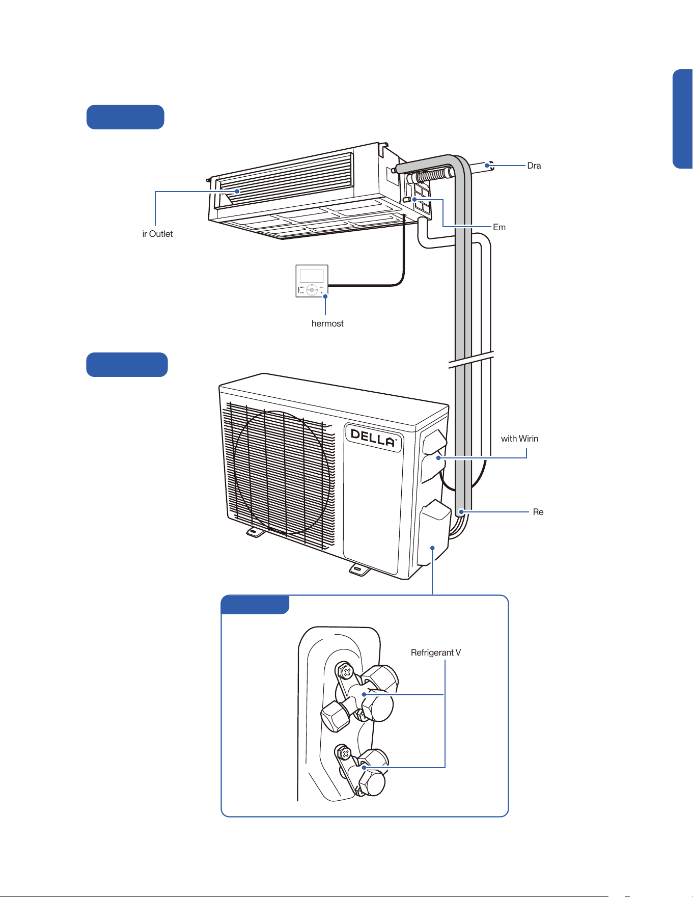
Name of Parts
Air Outlet
Indoor Unit
Outdoor Unit
Before Installation
Refrigerant Valves
Valve Cover
Wiring Terminal
with Wiring Diagram
Refrigerant Pipe
Emergency Drain Port
Drain Pipe
Thermostat
10
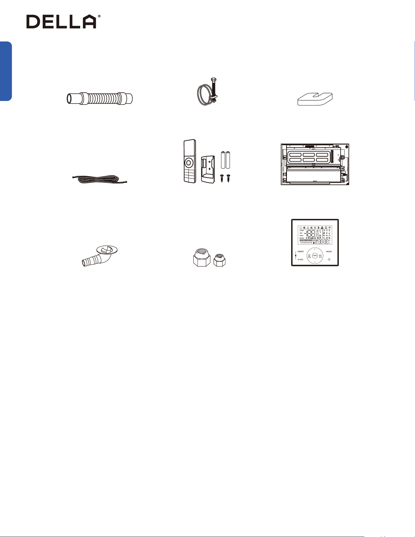
Hose Clamp
1x
Flexible Drain Hose
1x
Communication Cable
1x
Installation Template
1x
Drainage Joint
1x
Brass Nut Set
2x
Thermostat
1x
Rubber Foot Pad
4x
NOTE: Tools marked with * are needed for shortening the refrigerant pipe and / or electrical wire to the exact desired length.
ONLY a qualied HVAC technician should attempt altering the pipe length and / or the wire length.
Name of Parts
Included Accessories
Tools Needed (Not included)
Before Installation
Remote Control, Holder 1x
Battery 2x
• Screw Driver
• Hole Saw Ø2.75" / Ø70mm
• Refrigerant Leak Detector / Liquid Leak Detector
• Allen Wrench
• Spanner
• Torque Wrench
• Measuring Tape
• Spirit Level
• Stud Finder
• Thermometer
• Vacuum Pump
• Dry Wall Anchors / Molly Bolts
• Wood Screws
• Floor Mounting Base Kit / Wall Mount Kit
• Power Supply Cable
• Micron Gauge / AC manifold Gauge
• Copper Pipe Bender / Spring Bender
• Caulk
• Tubing Cutter*
• Pipe Reamer*
• Tubing Flaring Tool*
• Wire cutter*
ON
OFF

11
v.20251124U
Product Specication
048-DC-9K2V 048-DC-12K2V 048-DC-18K2V 048-DC-24K2V
Power Supply 208 V - 230 V / 60 Hz / 1P 208 V - 230 V / 60 Hz / 1P 208 V - 230 V / 60 Hz / 1P 208 V - 230 V / 60 Hz / 1P
Rated Cooling Capacity (Btu / h) 9500 11000 17000 22000
Rated Heating Capacity (Btu / h) 9500 12000 18000 25000
Cooling
Power Consumption 750 W 940 W 1450 W 1870 W
Rated Current 3.2 A 4.1 A 6.3 A 8.1 A
Heating
Power Consumption 800 W 1030 W 1805 W 2030 W
Rated Current 3.5 A 4.5 A 7.8 A 8.8 A
Noise Level
Indoor Unit 28 - 42 dBA 32 - 44 dBA 33 - 48 dBA 34 - 51 dBA
Outdoor Unit 54 dBA 56 dBA 59 dBA 61 dBA
Dimension
Indoor Unit
27.5” x 19.25” x 7.88”
700 mm x 490 mm x 200 mm
27.5” x 19.25” x 7.88”
700 mm x 490 mm x 200 mm
35.38" x 19.25" x 7.88"
900 mm x 490 mm x 200 mm
43.25" x 17.75" x 7.88"
1100 mm x 490 mm x 200 mm
Outdoor Unit
31.88" x 12.00" x 21.61”
810 mm x 305 mm x 549 mm
31.88” x 12.00” x 21.61”
810 mm x 305 mm x 549 mm
36.49" x 14.96" x 27.51"
927 mm x 380 mm x 699 mm
38.50" x 16.57" x 31.61"
978 mm x 421 mm x 803 mm
Net Weight
Indoor Unit 33.1 lb / 15 kg 33.1 lb / 15 kg 39.7 lb / 18 kg 50.7 lb / 23 kg
Outdoor Unit 52.7 lb / 23.9 kg 65 lb / 29.5 kg 90.4 lb / 41 kg 104.7 lb / 47.5 kg
Suitable Area Up to 400 sq. ft Up to 550 sq. ft Up to 1000 sq. ft Up to 1500 sq. ft
Moisture Removal (per hour) 2.3 pints / 1.1 L 3.3 pints / 1.6 L 4.6 pints / 2.2 L 5.5 pints / 2.6 L
Refrigerant R454B R454B R454B R454B
Before Installation
12
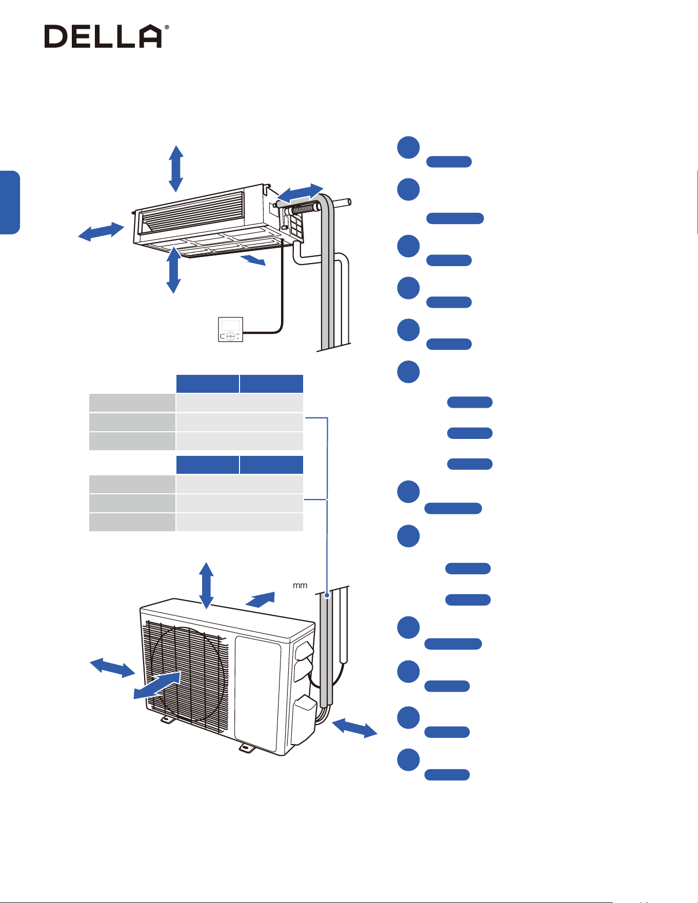
Installation Preview
1
3
4
5
2
6
7
≥ 4" / 100 mm
≥ 98.4" / 2500 mm
≥ 39.3" / 1000 mm
≥ 19.6" / 500 mm
≥ 10" / 250 mm
Choose the installation location
-00-
Install hanging rod
-00-
Hanging the indoor unit
-00-
Connect air duct to the indoor unit
-00-
Placing the outdoor unit
-00-
Vacuum Pumping
-00-
Installing Thermostat
-00-
Check List
-00-
Test Run
-00-
Connection between indoor and outdoor unit
• Connect the refrigerant pipes
-00-
• Connect the electrical wires
-00-
Indoor unit connection
• Connect the drain hose to the indoor unit
-00-
• Pass the electrical wire into the indoor unit
-00-
• Connect the refrigerant pipe to the indoor unit
-00-
Ceiling hole, refrigerant pipe, drain hose, and
electrical cable preparation
-00-
10
11
12
Installation
Page 14
Page 18
Page 19
Page 20
Page 22
Page 23
Page 27
Page 17
Page 32
Page 33
Page 40
Page 44
Page 45
Page 29
Page 36
8
9
≥ 11.8" / 300 mm
≥ 11.8" / 300 mm
≥ 19.7" / 500 mm
≥ 19.7" / 500 mm
≥ 79" / 2000 mm
9K2V 12K2V
Standard Length 16.4 ft / 5 m
Max. Distance 49 ft / 15 m
Max. Elevation 33 ft / 10 m
18K2V 24K2V
Standard Length 16.4 ft / 5 m
Max. Distance 65 ft / 20 m
Max. Elevation 49 ft / 15 m
13
v.20251124U
Installation Info (Power Supply, Breaker Size, Refrigerant & Pipe Set)
Power Supply and Breaker Size
048-DC-9K2V 048-DC-12K2V 048-DC-18K2V 048-DC-24K2V
Power Supply 203 V - 230 V / 60 Hz / 1P 203 V - 230 V / 60 Hz / 1P 203 V - 230 V / 60 Hz / 1P 208 V - 230 V / 60 Hz / 1P
Cooling
Power Consumption 750 W 940 W 1450 W 1870 W
Rated Current 3.2 A 4.1 A 6.3 A 8.1 A
Heating
Power Consumption 800 W 1030 W 1805 W 2030 W
Rated Current 3.5 A 4.5 A 7.8 A 8.8 A
Min. Circuit Ampacity 10 A 11 A 12 A 17 A
Min. Wire Size (American Wire Gauge) 16 AWG 16 AWG 12 AWG 12 AWG
Breaker Size 15 A 15 A 20 A 25 A
Refrigerant and Pipe Set Info
048-DC-9K2V 048-DC-12K2V 048-DC-18K2V 048-DC-24K2V
Stand Length 16.4 ft / 5 m 16.4 ft / 5 m 16.4 ft / 5 m 16.4 ft / 5 m
Max. Distance Between Indoor and Outdoor Unit 49 ft / 15 m 49 ft / 15 m 65 ft / 20 m 65 ft / 20 m
Max. Elevation Between Indoor and Outdoor Unit 33 ft / 10 m 33 ft / 10 m 49 ft / 15 m 49 ft / 15 m
Type of Refrigerant R454B R454B R454B R454B
Factory Refrigerant Pre-charge for up to 25 ft pipe 25 oz / 710 g 35.27 oz / 1000 g 45.50 oz / 1290 g 55.03 oz / 1560 g
Additional Refrigerant Charge 0.11 oz / ft (10 g / m) 0.11 oz / ft (10 g / m) 0.11 oz / ft (10 g / m) 0.11 oz / ft (10 g / m)
Max. Refrigerant Charge 27.69 oz / 785 g 37.92 oz / 1075 g 48.15 oz / 1365 g 57.67 / 1635 g
Liquid
Line
Pipe Diameter 1/4” 1/4” 1/4” 1/4”
Torque Parameter
18 - 20 N-M / 13.3 - 14.8 lbf-ft /
1.8 - 2.0 kgf-m
18 - 20 N-M / 13.3 - 14.8 lbf-ft /
1.8 - 2.0 kgf-m
18 - 20 N-M / 13.3 - 14.8 lbf-ft /
1.8 - 2.0 kgf-m
18 - 20 N-M / 13.3 - 14.8 lbf-ft /
1.8 - 2.0 kgf-m
Gas Line
Pipe Diameter 3/8” 3/8” 1/2” 5/8”
Torque Parameter
30 - 35 N-M / 22.1 - 25.8 lbf-ft /
3.0 - 3.6 kgf-m
30 - 35 N-M / 22.1 - 25.8 lbf-ft /
3.0 - 3.6 kgf-m
45 - 50 N-M / 33.2 - 36.9 lbf-ft /
4.6 - 5.1 kgf-m
60 - 65 N-M / 44.3 - 48.0 lbf-ft /
6.1 - 6.6 kgf-m
Installation

14
• Ensure the installation complies with the minimum clearance space surrounding the unit and is within the maximum piping length and
maximum elevation defined in the installation information.
-00-
• Make sure the ceiling / structure is strong enough to hold the weight of the indoor unit and prevent it from vibration.
• Make sure the air inlet and outlet are clear of any obstruction.
• Make sure condensation can be easily drained.
• A place where all connections can be easily made to the outdoor unit.
• A place where the indoor unit is out of children’s reach.
• A place where the indoor unit is accessible for maintenance.
• Install the indoor unit 10 ft / 3 m away from TV or radio appliances.
NOTE: Radio interference may occur if appliances are placed too close to each other.
• Do not install in a laundry room or by a swimming pool.
• There should not be any heat source near the indoor unit.
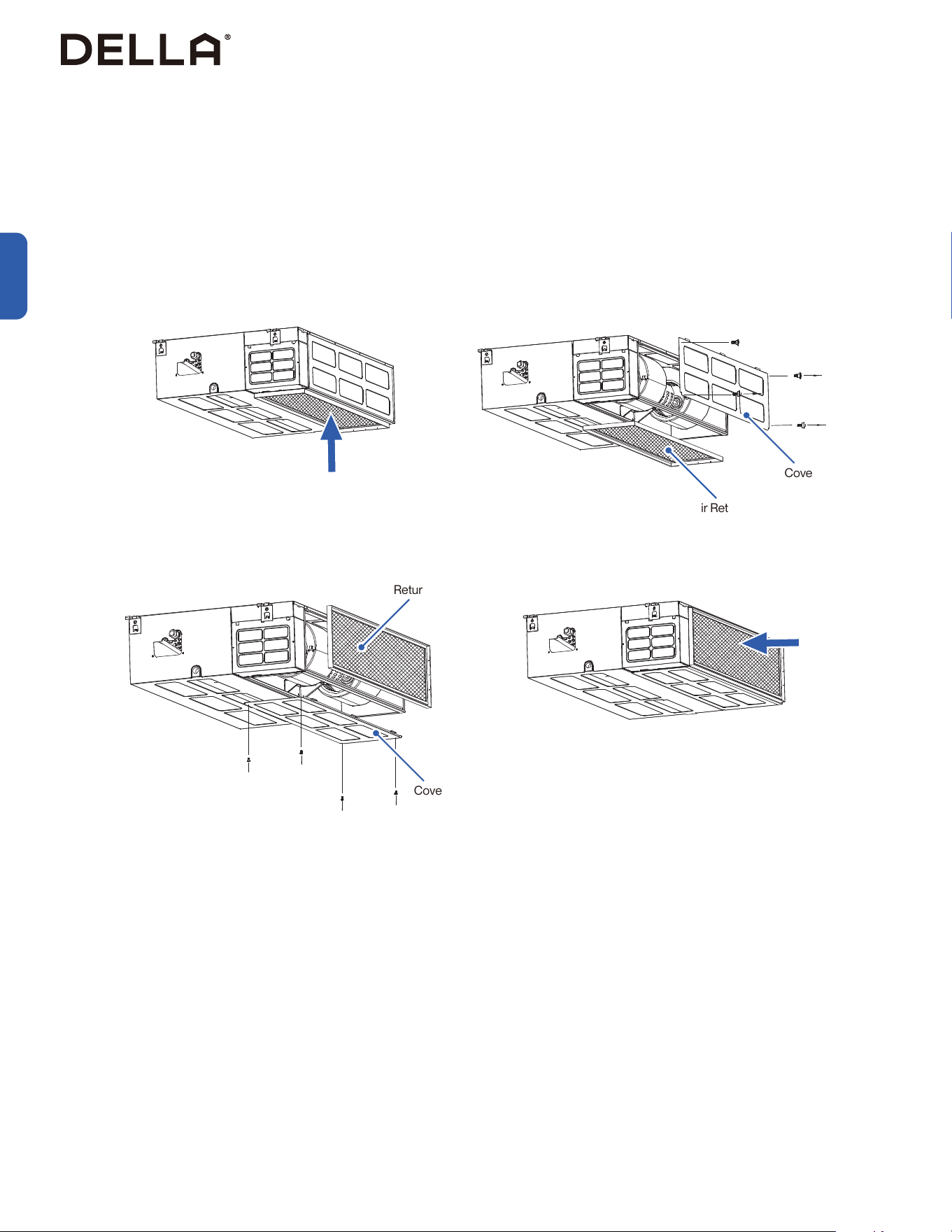
• Do not install the indoor unit near the doorway.
To prevent the indoor unit from falling down and blocking exit way in case of an emergency such as fire or earthquake etc.
• Do not install the indoor unit where causticgas exist in the air.
To prevent copper alloy, or aluminum panels in the indoor unit from corrosion.
• Do not install the indoor unit in area with strong electreomagnetic wave.
Installation Info
Picking a Installation Location for the Indoor Unit
Picking a Installation Location for the Outdoor Unit
• Do not install the outdoor unit near a heat source, steam, or flammable gas.
• Do not install the outdoor unit in windy or dusty locations.
• Do not install the outdoor unit in places where people often pass.
• Avoid installing the outdoor unit in places where it will be exposed to direct sunlight.
NOTE: If necessary, build a protection that does not interfere with the airflow.
• Make sure there is enough space around the outdoor unit to circulate air.
-00-
• Outdoor unit must be placed in a safe and solid location.
• The outdoor unit should ideally be placed on a elevated concrete pad.
• If installing in snowy region, it is recommended the outdoor unit to be installed above the seasonal snow level.
Installation
Page 13
Page 12
15
v.20251124U
048-DC-9K2V-IN
048-DC-12K2V-IN
048-DC-18K2V-IN
048-DC-24K2V-IN
Unit in millimeter (mm)
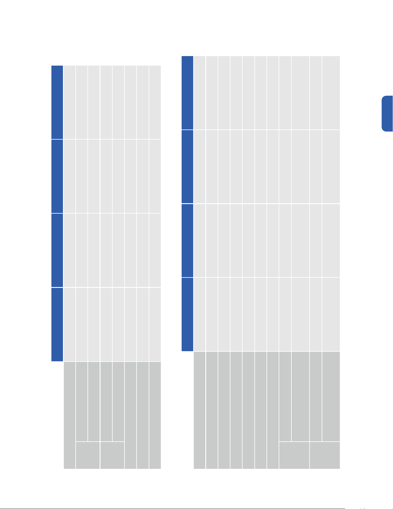
Indoor Unit Installation
Indoor Unit Dimension
Installation
Mounting Lug Dimension Air Outlet Opening Air Return Opening
Length Width Length Width Length Width
9 - 12K 738 298 510 140 600 187
18K 958 298 730 140 820 187
24K 1138 365 930 140 1030 183
Air Outlet Opening
Mounting Lug
Dimension
Width
Mounting Lug
Dimension
Width
Mounting Lug Dimension Length
Mounting Lug Dimension Length
Air Outlet Opening
Air Return Opening
Air Return Opening
16
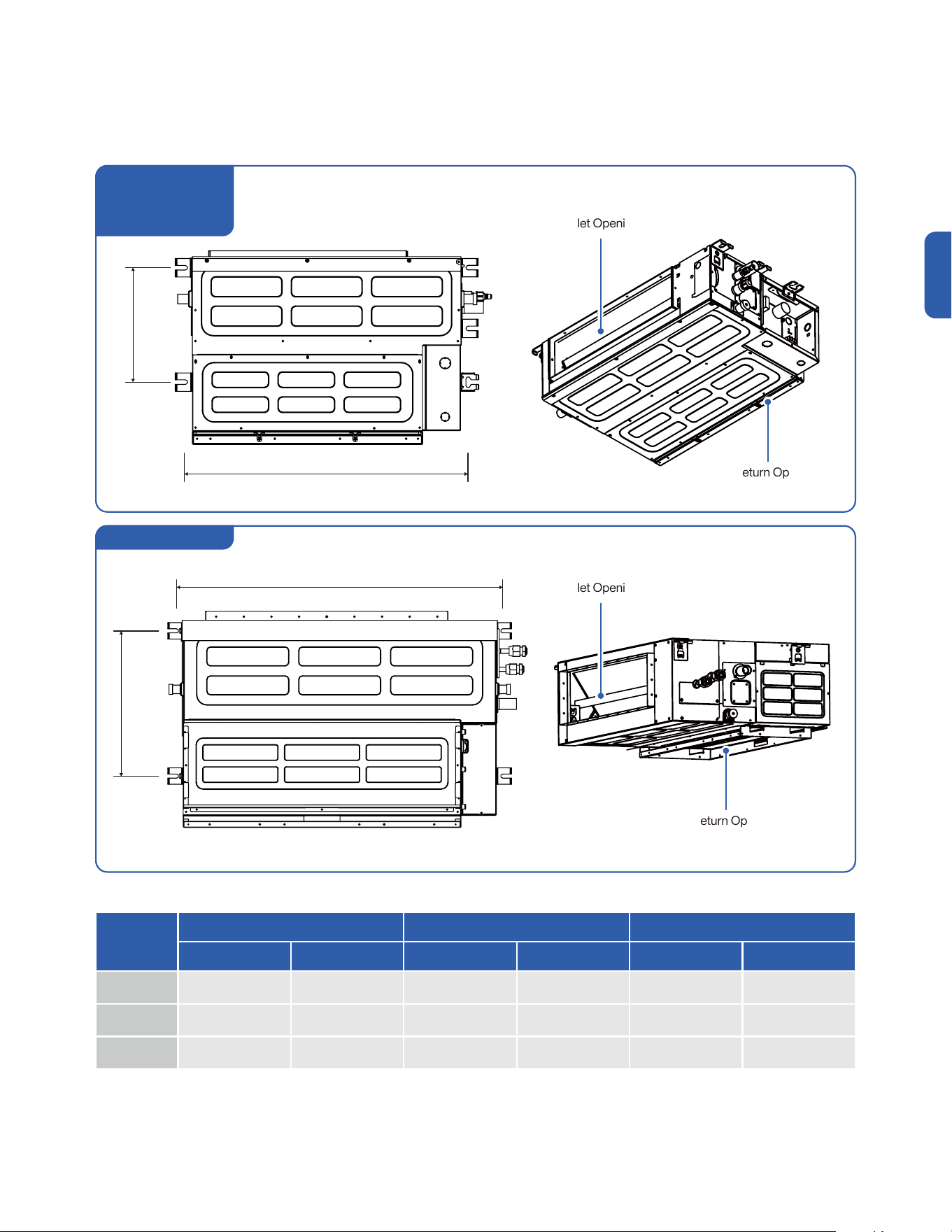
Indoor Unit Installation
Deciding Air Return Position
Installation
The indoor unit is fitted with the air return at the bottom position.
Swap the air return and cover plate position to change the air return to the back position.
1. Remove the air return filter and the back cover from the indoor unit.
2. Re-install the cover to the bottom of the indoor unit and the air return filter to the back.
Cover
Cover
Air Return Filter
Air Return
Air Return
Air Return Filter
17
v.20251124U
Indoor Unit Installation
Installation
Prepare Refrigerant Lineset, Drain Pipe, and Electrical Cable
1. Route the refrigerant lineset, drain pipe, and electrical cable from the indoor unit installation location to the outdoor unit installation location.
Detail information on handling refrigerant line set on -00- .
Detail information on drain pipe on -00- .
2. Depending on the building, you can route the lineset toward the outside through an opening on the wall or the soffit.
Page 25
Page 21
• Always insert the sleeve into the wall hole and seal the surrounding with putty / caulk.
This will prevent water, insects, or small animals from getting into the house.
Indoor Unit
Installation Location
Indoor Unit
Installation Location
18
Indoor Unit Installation
Installation
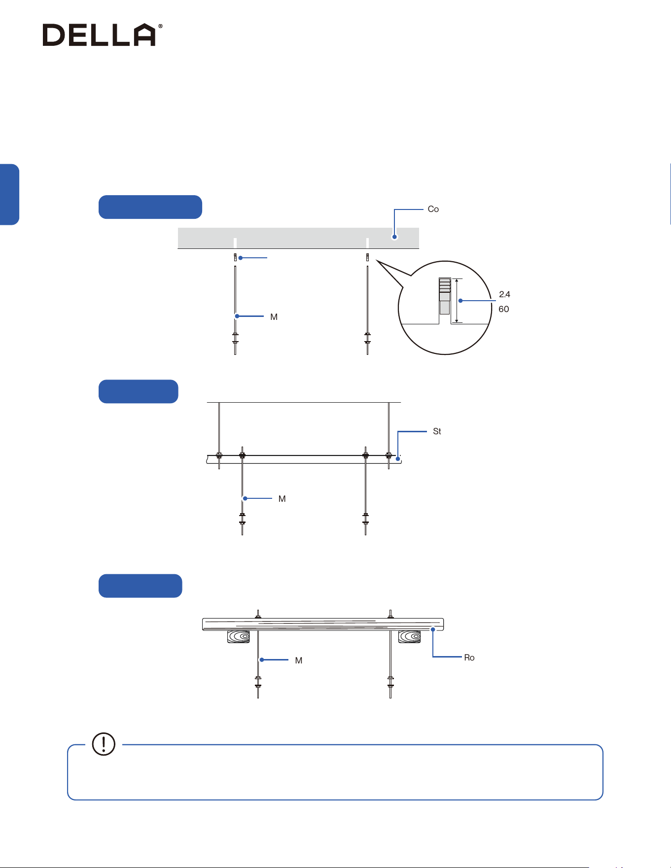
Attaching Threaded Rods for Hanging
On Wood Beam
On Concrete / Brick
On Steel Beam
Roof Beam
M10 Threaded Rod
M10 Threaded Rod
Drop-in Anchor
M10 Threaded Rod
Concrete / Brick
2.4" - 2.8”/
60 - 70mm
Steel Beam
• It is recommended to use threaded rod wrench to tighten the threaded rod into the drop in anchor and make sure it can support the
weight of the cassette unit and withstand operating vibration.
1. Using the installation template and mark the threaded rods attaching locations.
Make sure the indoor unit refrigerant ports and drain port is facing the pre-routed refrigerant lineset and drain pipe.
2. Drill pilot holes on the marks.
3. Choose and attach the suitable anchor for your structure ceiling.
4. Cut M10 threaded rods into correct length and attach them into the anchors.
19
v.20251124U
Indoor Unit Installation
Installation
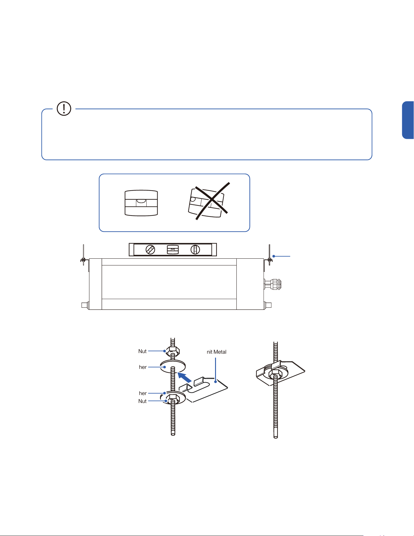
Hanging the Indoor Unit
1. Attach M10 nuts and M10 washers to the threaded rod at the hanging height.
2. Hang the hanging brackets to the M10 washers.
3. Level the unit all around with a bullseye spirit level and tighten the M10 nuts to secure the unit in place.
Indoor Unit Metal Hanging Bracket
M10 Nut
M10 Washer
M10 Washer
M10 Nut
• Lift the indoor unit to the ceiling with 2 people, or with the help of a power lifter. Carring the indoor unit alone without assisstant would
result in injury.
• A bull's eye level is recommended to be used to level the indoor unit. The indoor unit is equipped with a built-in drain pump and oat
switch. Failing to level the unit may cause oat switch to malfunction and cause water leakage.
Hanging Bracket
20
Indoor Unit Installation
Installation
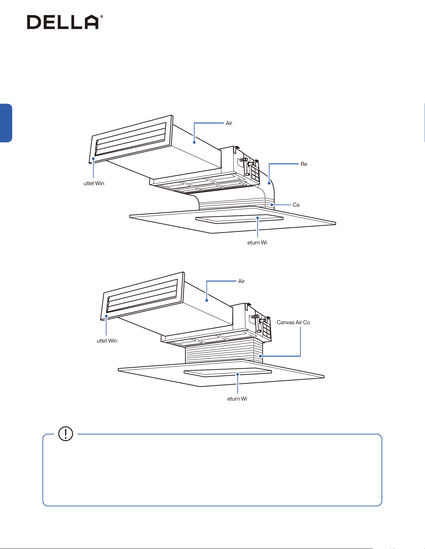
• In the case of using a round air outlet window, connect the indoor unit to a rectangular to round transition conduit.
• Air outlet conduit and return conduit should be equipped with heat-insulating layer to minimize energy loss in transmission process
and limit condensation from forming.
• Air conduit and return conduit should be secured in place with suspension rod. All connection should be tightly sealed by gasket
cement.
• To minimize energy loss, air pipe and air conduit should be equipped with heat-insulating layers.
Connect Air Duct
1. Attach one end of the air conduit to the indoor unit air outlet by rivet, the other end to a air outlet window in the room. Make sure the total
length should be within 19.6ft or 6m.
2. Connect a canvas air conduit to the indoor unit air return and the other end to a air return window.
Canvas Air Conduit
Air Outlet Window
Air Outlet Window
Air Conduit
Return Air Conduit
Air Conduit
≤ 19.5’ / 6 m
≤ 19.5’ / 6 m
Air Return Window
Air Return Window
Canvas Air Conduit
21
v.20251124U
Indoor Unit Installation
Installation
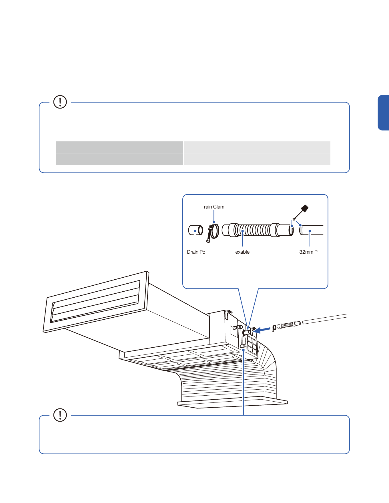
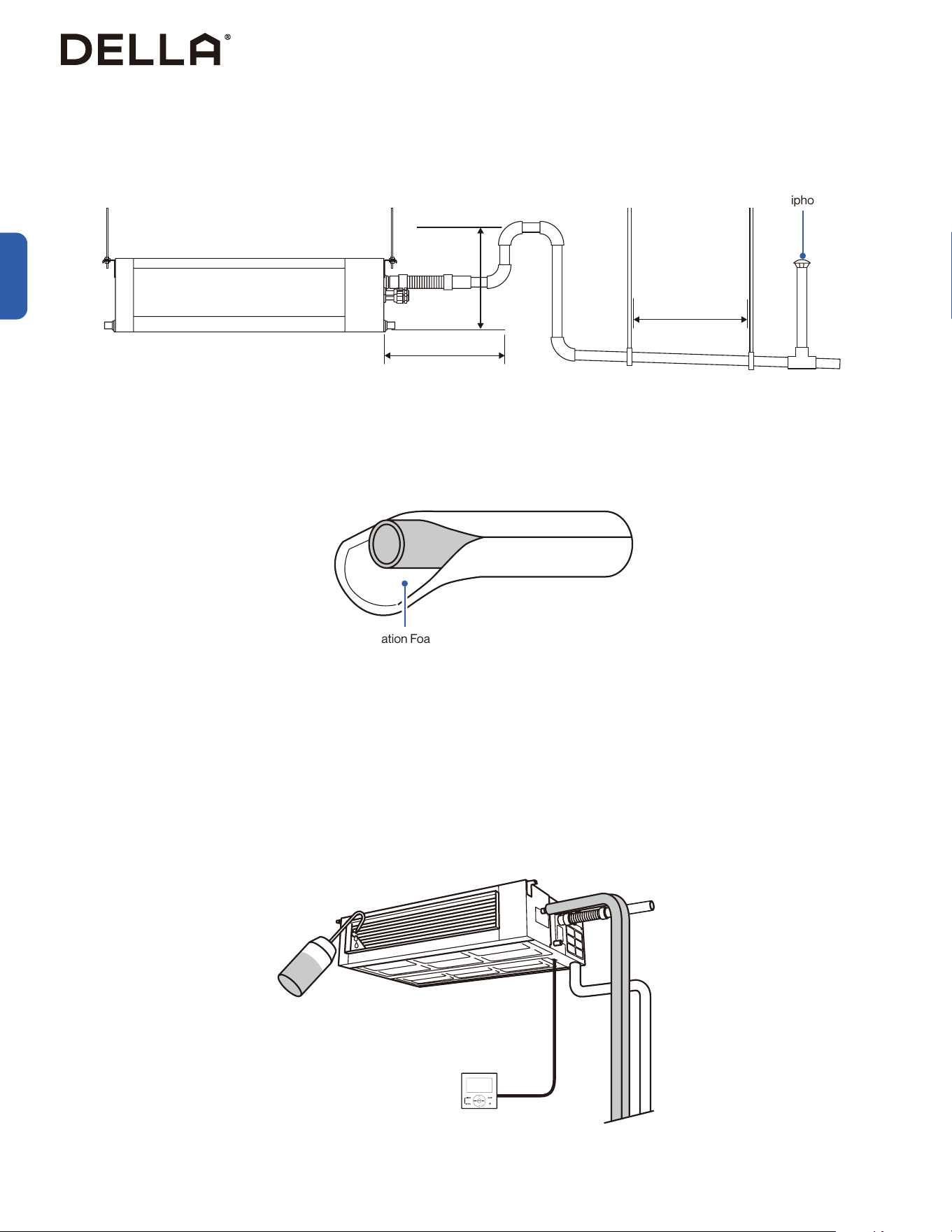
Connect Drain Hose
1. Attach drain pipe to the indoor unit.
2. Make sure the connection is tightly secured.
3. Wrap the connection and the drain pipe with insulating foam.
• The drain pipe and all its connection must be wrapped with insualting foam to prevent condensation from building up on the pipe's
surface, which may result in water dripping in the ceiling.
• The following should be used for drain pipe installation:
Drainage Pipe Material Ø32mm Polyvinyl Chloride (PVC) pipe
Heat Insulation Material 10mm Thick Foamed Polyethylene Insulation Plate
Drain Port Flexable Drain Hose Ø32mm PVC
Drain Pipe
PVC Pipe Cement
• For the ease of future maintenance and servicing, use a
drain clamp to secure the drain hose to the drain port.
Drain Clamp
• The transparent drain port should only be used during maintance or service work. It should be plugged during normal operation.
• Do not connect the drain pipe to the transparent drain port.
• Transparent drain port can be connected to a Ø21mm drain pipe during maintance or service work.
22
Indoor Unit Installation
Installation
Drain Test
Anti-Siphon Vent
• A water pipe trap should be installed near the opening of the drain pipe to create a barrier that prevents harmful and foul-smelling gases
from back flowing into the indoor unit.
• When using a long drain pipe, hang the pipe in place every 39” - 78”.
• Wrap the drain hose, drain pipe, and all connections with insulation foam. (10mm think foamed polyethylene insualtion plate)
Connect Drain Hose
≤ 11.8”’ / 300 mm
≤ 39’ / 1000 mm
39” - 78” /
1000 - 2000 mm
Insulation Foam
1. Temporart disconnect the air conduit from the air outlet.
2. Turn on the AC and set it in COOL mode.
3. Slowly pour 1000 ml of water into the drain pain via the air outlet opening and make sure there is no leakage or back flow of water.
4. After the drain test, reconnect the air conduit to the air outlet.
Perform a drain test after installing the whole unit to check if there is any water leak.
23
v.20251124U
Indoor Unit Installation
Installation
Connecting the Electrical Cable
1. Feed communication cable into a electrical conduit that leads to the wall hole.
2. Feed thermostate cable into another electrical conduit.
3. Remove the terminal covers from the indoor unit.
4. Punch out the knockout hole on underneath the terminal.
5. Insert the electrical cable through the knock out hole into the terminal
6. Connect the wires to the corresponding terminal and secure the cable using the cable clamp.
7. Put the terminal cover back in place.
NOTE: Exact electrical diagram can be found on the back of the terminal cover.
Electric Terminal Cover
Knockout Hole
Communication Cable
to Outdoor Unit
Wire Control Cable
to Thermostat
24
Indoor Unit Installation
Installation
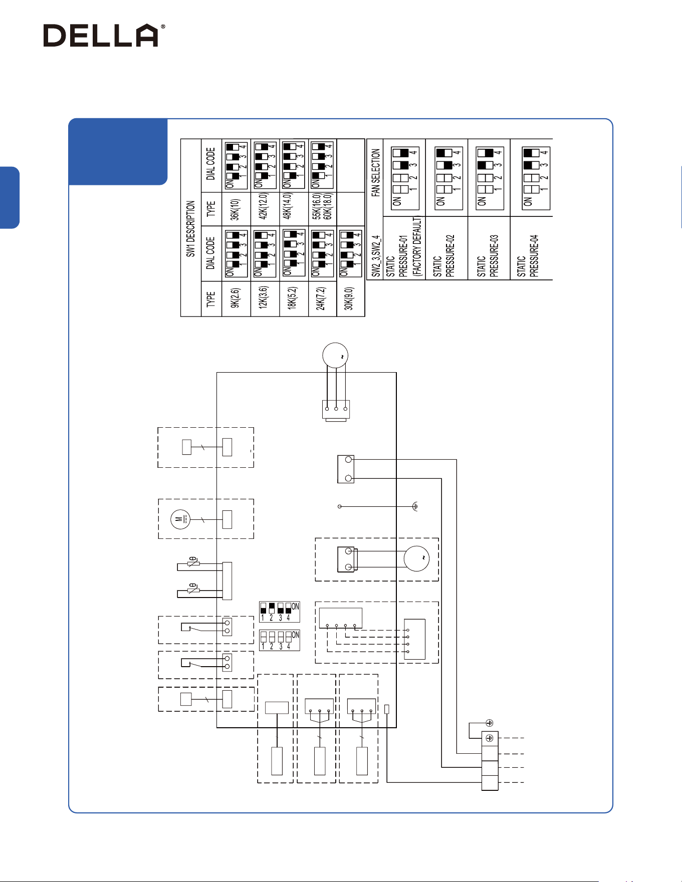
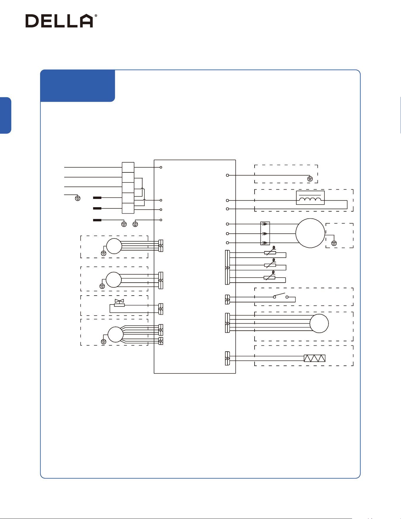
Indoor Unit Circuit Diagram
048-DC-9K2V-IN
048-DC-12K2V-IN
048-DC-18K2V-IN
048-DC-24K2V-IN
1 2 3
Y/G
BLU BRN
N L
POWER
Outdoor
Unit
OUT-FAN
DC-FAN
MF1
CN15
CN1
GRN
P0
PCB
AC-PUMP
MP1
CN17
OPTIONAL
G(E)
A
B
+12V
+12VBAG(E)
CN12
485-WIRE
WIRED REMOTE
OPTIONAL
BLK
S(S1)
B
ABMS
G(E)
CN20-1
BMS-485
3
OPTIONAL
B
A
BMS
G(E)
CN20
BMS-485
3
OPTIONAL
OPTIONAL
DISPLAY
CN8
Dis-port
10
CN18
WIFI
4
OPTIONAL
CN7
water
SW
OPTIONAL
CN11
Door-F
OPTIONAL
SW1 SW2
CN6
IPT RT
Coil Temp. Sensor
R25=5K
R25=5K
Ambient Temp. Sensor
CN14
DC-Pump
3
OPTIONAL
CN9
R_CAD
3
OPTIONAL
Dry Contact
25
v.20251124U
Installation
Indoor Unit Installation
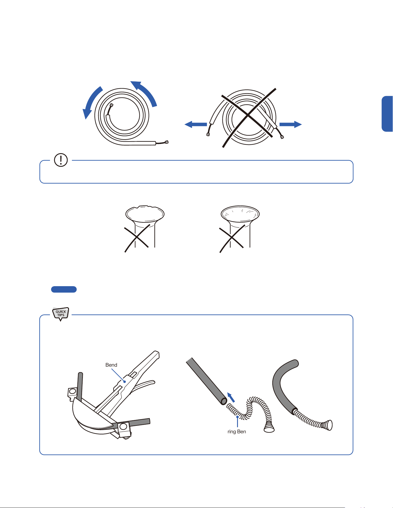
1. Unroll the included refrigerant pipe.
2. Remove the cover and make sure the ports are clean and smooth.
3. In the case of a imperfect flaring or the pipe needs to be shorten for the installation, refrigerant pipe should be cut and flare by qualified
technician.
-00-
Imperfect Flaring Dirty Flaring
• Do not pull the refrigerant pipe to prevent the pipe from kinking or bending.
Preparing the Refrigerant Pipe
Page 21
Pipe Bender
Spring Bender
• Use a pipe bender or spring bender to shape the refrigerant pipes along wall and corners. Bending the pipe without bending tools
would easily kink or damage the pipe, which would cause refrigerant starvation, or leakage in the system.
26
Indoor Unit Installation
Installation
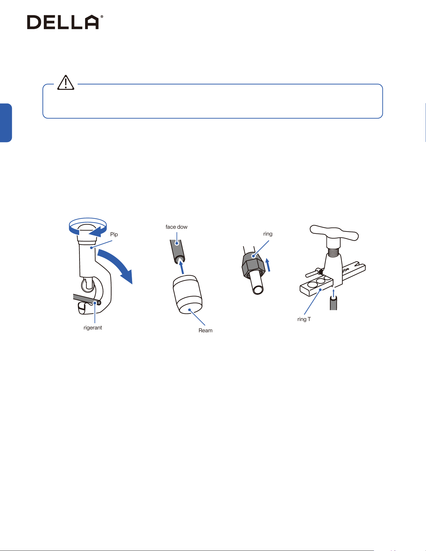
Cutting and Flaring Refrigerant Pipe
1. Cut the copper pipe with a pipe cutter.
2. Remove any burrs or rough edges with a reamer with the pipe facing downward.
NOTE: The opening of the pipe must face toward the ground to prevent chips or dust from entering the pipe.
3. Insert the flare nut to the pipe.
4. Use the flaring tool to flare the copper pipe. The flaring angle must match to that of the refrigerant lines from the unit.
Pipe Cutter
Flaring Nut
Flaring Tool
Refrigerant Pipe
Refrigerant Pipe
(Must face downward)
• Any refrigerant pipe alternation should only be done by qualied technician. Incorrect work may cause refrigerant leak, reduce cooling /
heating eciency, damage to the unit. Warranty does not cover any damage(s) caused by incorrect refrigerant pipe alternation.
Reamer
WARNING
27
v.20251124U
Installation
Indoor Unit Installation
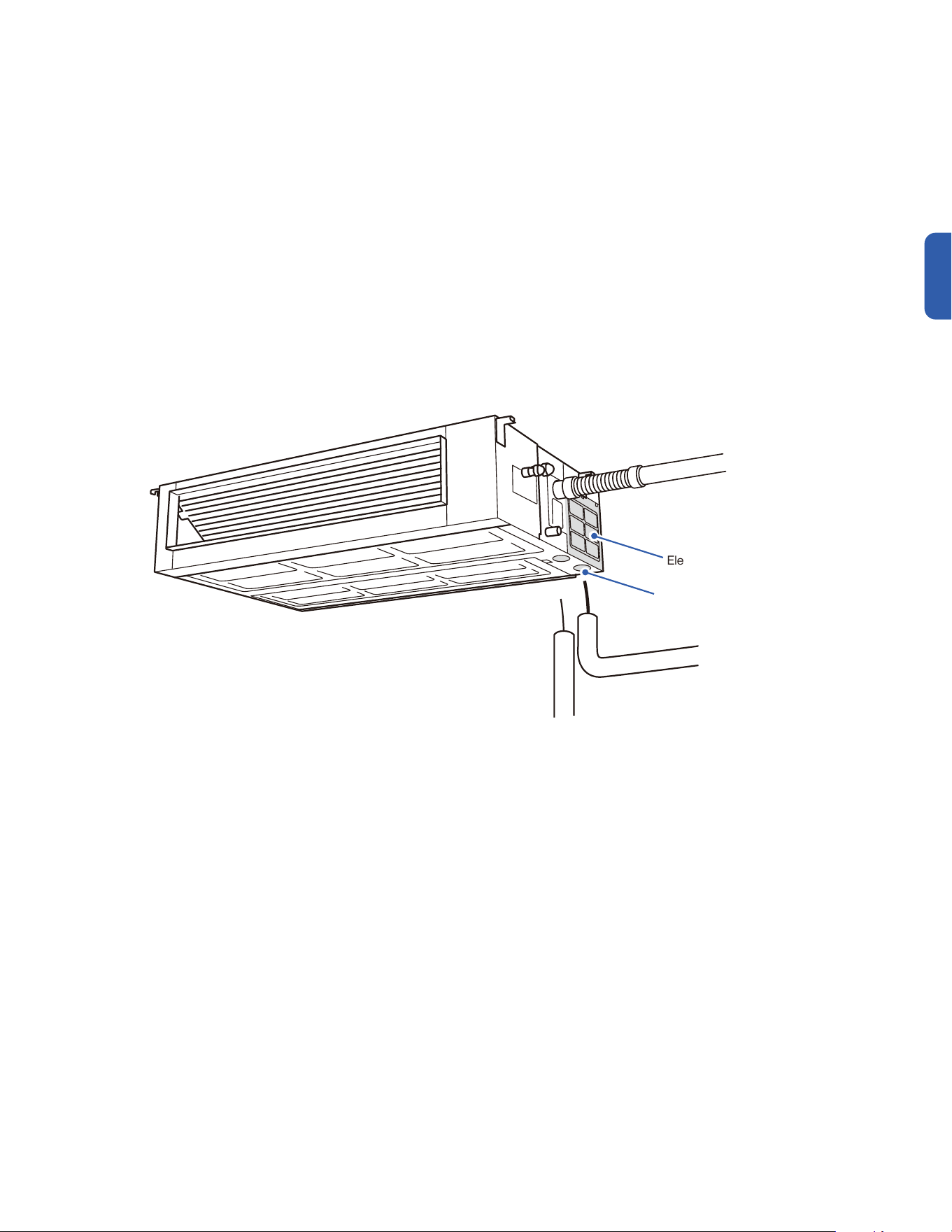
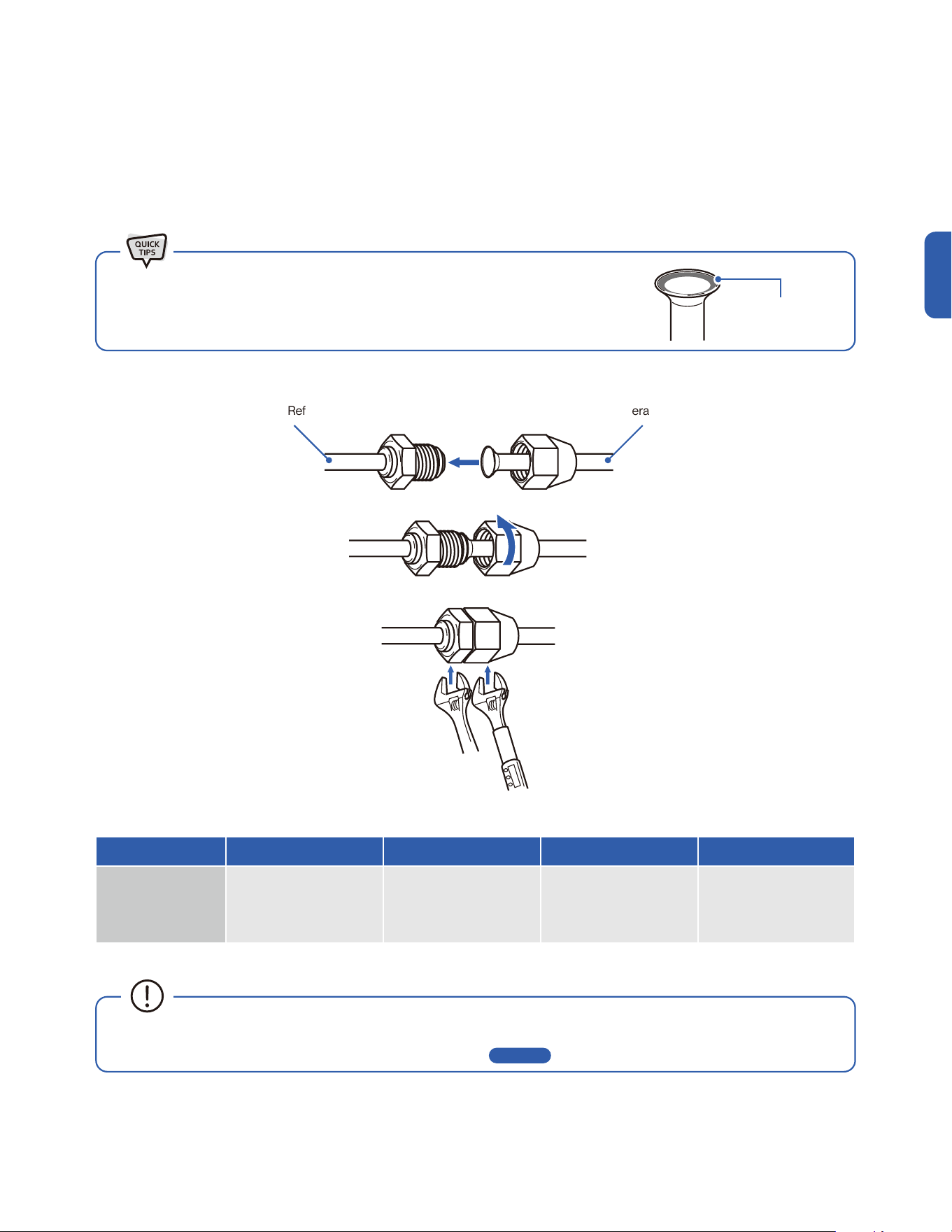
Connecting Refrigerant Pipe to the Indoor Unit
Refrigerant PipeIndoor Unit Refrigerant Port
1. Remove the protective caps from the refrigerant pipes and from the indoor unit refrigerant port.
2. Align the refrigerant pipe straight to the port, then tighten the nut by hand.
3. Use a torque wrench to tighten the nut according to the torque requirement.
• A thin layer of nylog can be applied to the inside of the are to provide better seal. (OPTIONAL)
• Make sure no nylog is on the outside of the are.
Thin layer of nylog
(OPTIONAL)
Pipe Diameter 1/4" 3/8” 1/2” 5/8”
Torque Parameter
18 - 20 N-M
13.3 - 14.8 lbf-ft
1.8 - 2.0 kgf-m
30 - 35 N-M
22.1 - 25.8 lbf-ft
3.0 - 3.6 kgf-m
45 - 50 N-M
33.2 - 36.9 lbf-ft
4.6 - 5.1 kgf-m
60 - 65 N-M
44.3 - 48.0 lbf-ft
6.1 - 6.6 kgf-m
• Connection must be torque tighten to prevent leak. Do not over tighten.
• Refrigerant piping and torque requirement for specic model is on -00- .
Page 13
Hold Torque Tighten
28
Indoor Unit Installation
Installation
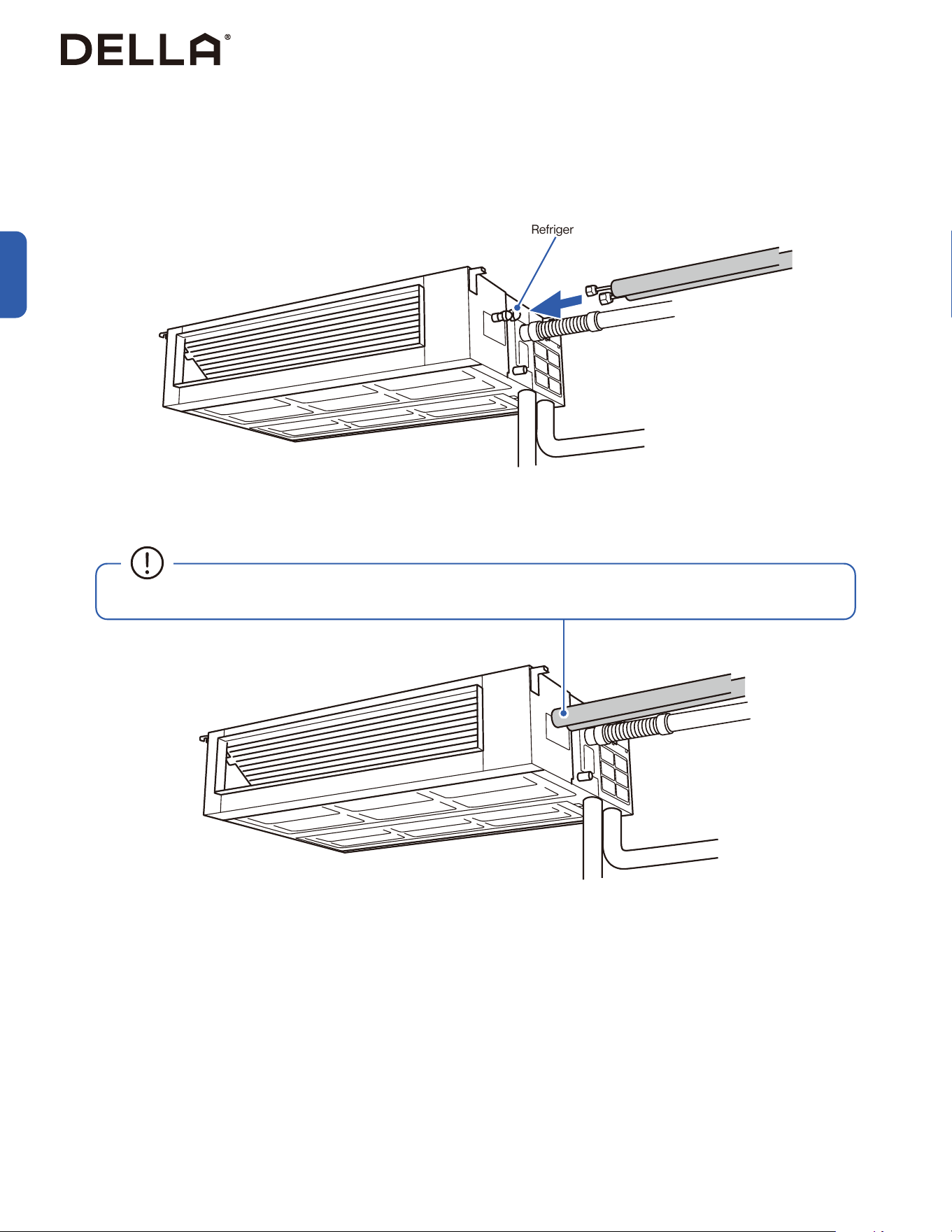
Connecting Refrigerant Pipe to the Indoor Unit
Refrigerant Port
• The refrigerant pipe and connection joint should be wrapped in heat insulating materials and prevent the formation of condensed air.
29
v.20251124U
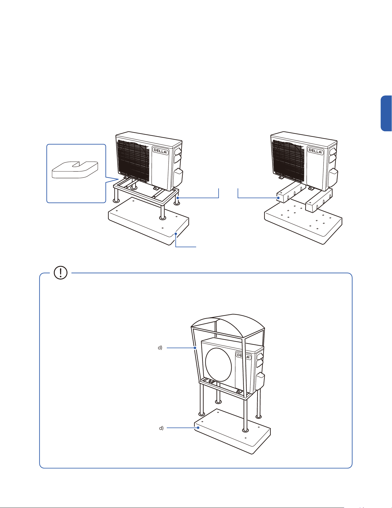
1. Place a concrete pad on the installation location.
NOTE: You do not need a concrete pad if the ground is concrete.
2. Mount the indoor unit on a mounting stand or base kit.
NOTE: Rubber foot pads can be placed between the outdoor unit and the mounting kit to reduce vibration or noise.
3. Drill holes on the concrete pad or concrete ground.
4. Secure the mounting stand or base kit on the concrete with concrete anchor bolts.
Outdoor Unit Installation
Secure the Outdoor Unit (Ground Installation)
Installation
Concrete Pad (Not Included)
Mounting Stand / Base Kit
(Not Included)
Concrete Pad (Not Included)
• Outdoor unit should be installed on a elevated mounting stand with snow cover if using in a snowy region.
Elevated snow cover (Not included)
Rubber foot pad
(Optional)
30
Installation
Outdoor Unit Installation
Secure the Outdoor Unit (Wall Installation)
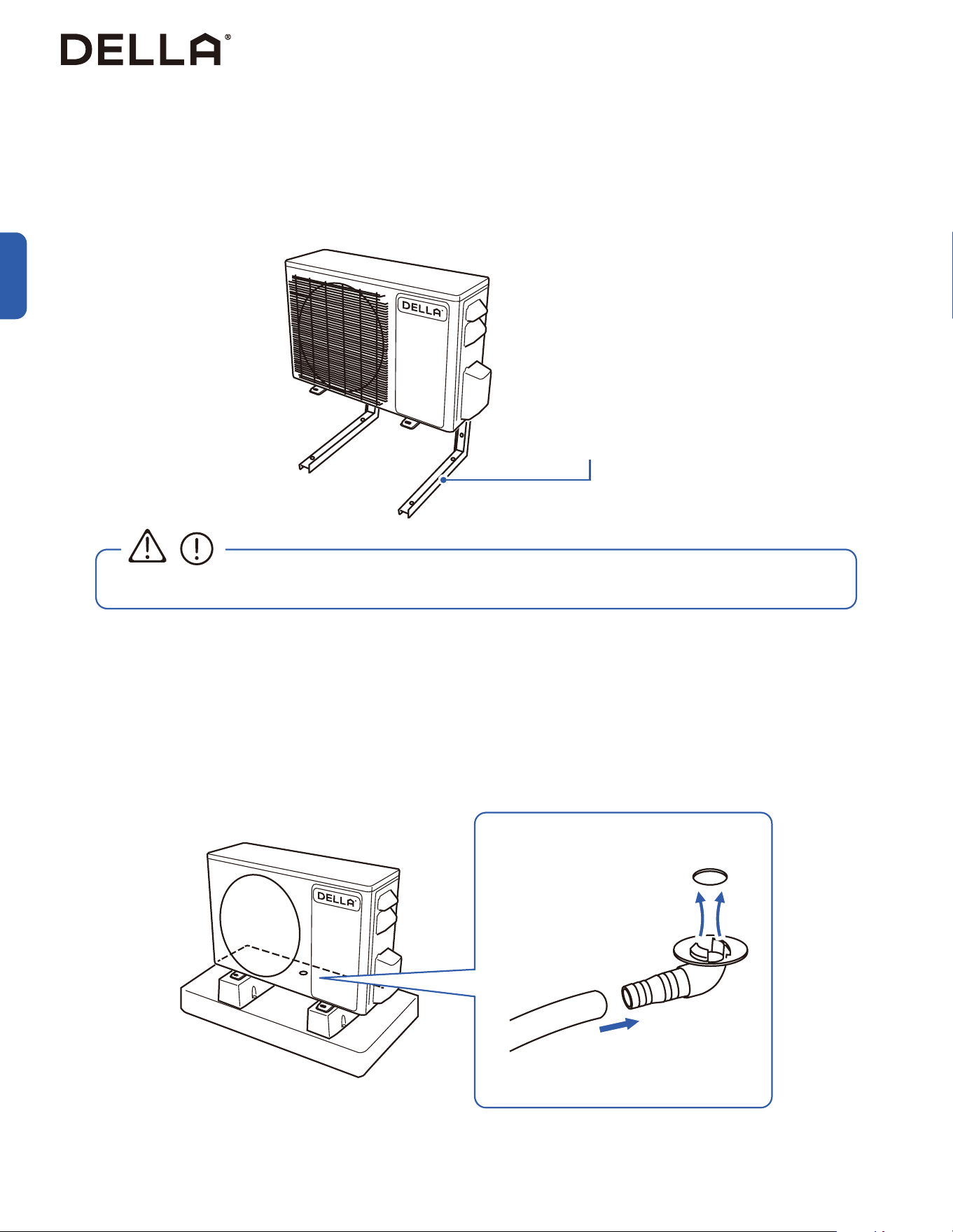
1. Drainage joint installation is recommended for heat pump models.
2. Insert drainage joint into the bottom hole of the outdoor unit.
3. Connect one end of the drain hose to the joint and the other end to your desired drainage point.
1. Measure the distance between the outdoor unit’s legs.
2. Mount the wall mounting bracket on the wall.
3. Secure the outdoor unit on the wall mounting bracket.
The outdoor unit can be fixed on a wall mounting bracket if there is no ground mounting option.
Outdoor unit drainage helps prevent condensation or frost inside the unit during cold weather.
Wall Mount Bracket
(Not Included)
• The wall mounting bracket and the wall must be able to support at least 4 times the weight of the outdoor unit.
Attach Drainage Port and Hose
CAUTION
Drainage Joint
Ø0.6" / Ø15 mm
Drain Hose
31
v.20251124U
Liquid Line
Liquid Line
Gas Line
Gas Line
Installation
Outdoor Unit Installation
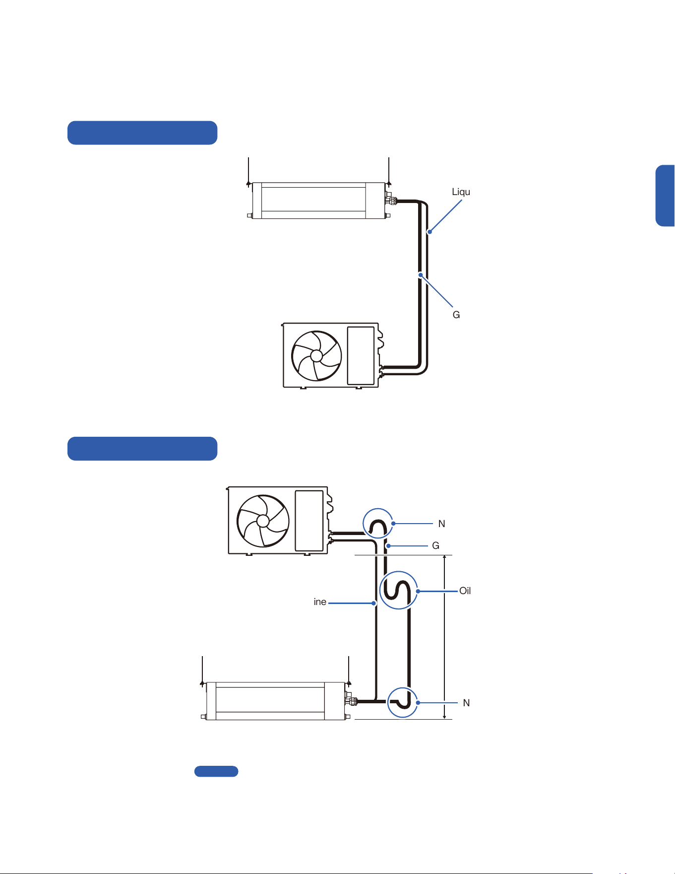
• Install an oil return bend
every 20ft / 6m
• Oil return bend and non-return bend at the lowest and highest position of the gas line is necessary when installing the outdoor unit above
the indoor unit.
• Refrigerant pipe handling on -00-
Connect the Refrigerant Pipes to the Outdoor Unit
Outdoor Unit Below Indoor Unit
Outdoor Unit Above Indoor Unit
Oil Return
Non-Return Bend
Non-Return Bend
Page 25
32
Installation
Outdoor Unit Installation
Connect the Refrigerant Pipes to the Outdoor Unit
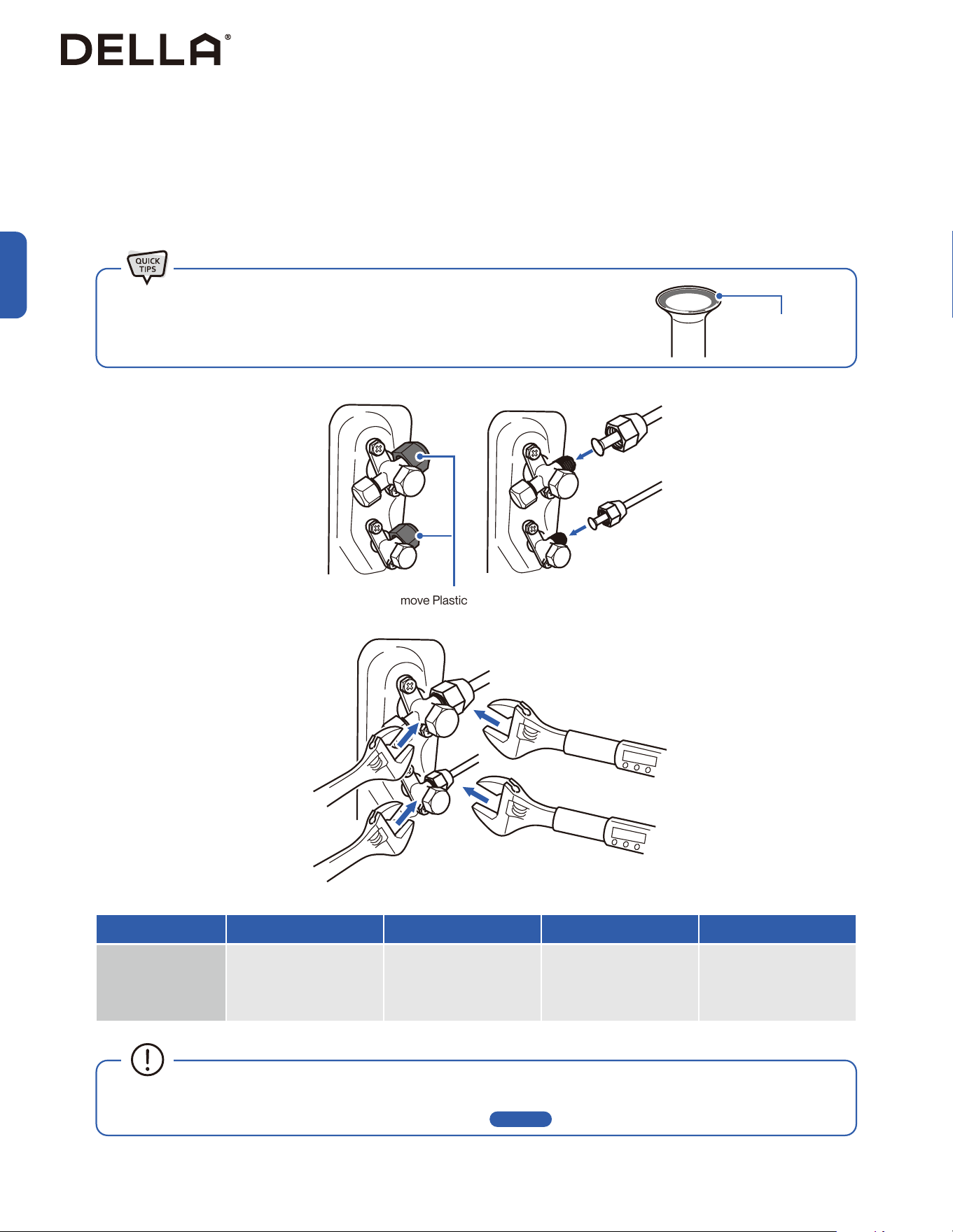
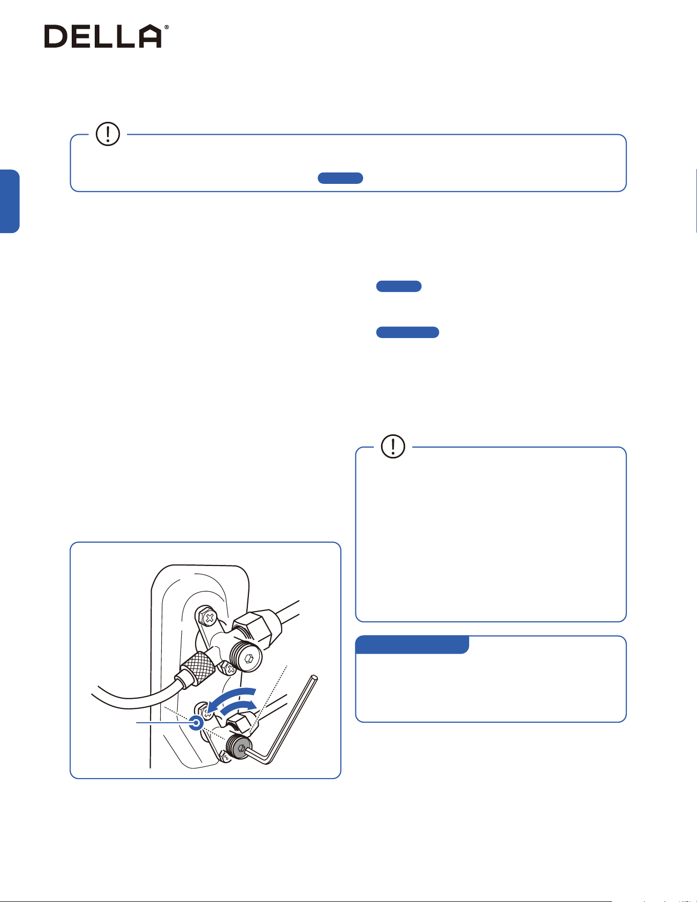
1. Unscrew the screws on the valve cover, press it down gently and remove the cover from the outdoor unit.
2. Remove plastic caps from the end of the valves.
3. Align the refrigerant pipes straight to the outdoor unit valve, then tighten the nut by hand.
4. Use a torque wrench to tighten the nut according to the torque requirement.
• A thin layer of nylog can be applied to the inside of the are to provide better seal. (OPTIONAL)
• Make sure no nylog is on the outside of the are.
Thin layer of nylog
(OPTIONAL)
Remove Plastic Caps
Hold
Hold
Torque Tighten
Torque Tighten
Pipe Diameter 1/4" 3/8” 1/2” 5/8”
Torque Parameter
18 - 20 N-M
13.3 - 14.8 lbf-ft
1.8 - 2.0 kgf-m
30 - 35 N-M
22.1 - 25.8 lbf-ft
3.0 - 3.6 kgf-m
45 - 50 N-M
33.2 - 36.9 lbf-ft
4.6 - 5.1 kgf-m
60 - 65 N-M
44.3 - 48.0 lbf-ft
6.1 - 6.6 kgf-m
• Connection must be torque tighten to prevent leak. Do not over tighten.
• Refrigerant piping and torque requirement for specic model is on -00- .
Page 13
33
v.20251124U
Installation
Outdoor Unit Installation
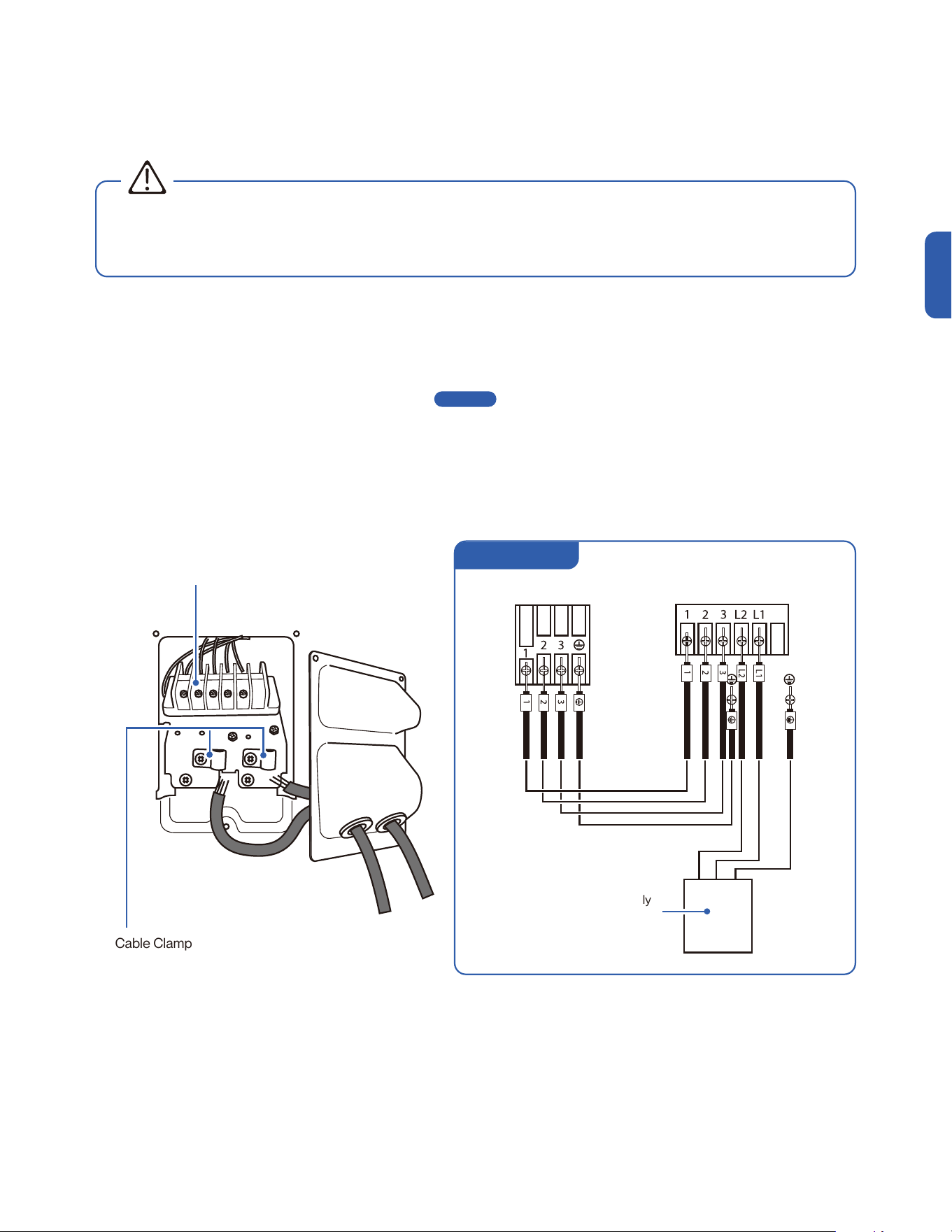
For 220V Unit
Connect the Electrical Wire
Terminal Block
Indoor Terminal Outdoor Terminal
Power Supply
w/ Breaker
Cable Clamp
1. Unscrew the screws from the wiring cover, press the cover downward gently, and remove from the outdoor unit.
2. Unscrew the cable clamp.
3. Insert the communication cable from the indoor unit through the opening on the cover, then connect the wires to the outdoor unit terminal.
4. Insert power supply cable (not included) to the opening on the cover, then connect the wires to the outdoor unit terminal.
5. Turn off any power from the power supply, and connect the power supply cable to the power supply circuit box.
Exact power supply cable and breaker size requirement on -00-
6. Reinstall the wiring cover to its original place.
Page 13
• Electrical wiring must be done by a qualified technician or electrician. Failing to connect the wires correctly will cause short circuit, a
fire, and property damage.
• Do not use the communication cable as power supply cable.
WARNING
34
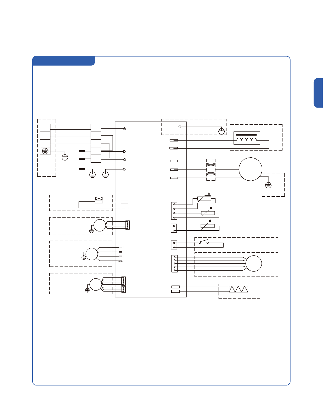
Outdoor Unit Installation
Outdoor Unit Circuit Diagram
Installation
048-TP-9K2V-24S-OUT
048-TP-12K2V-24S-OUT
048-TP-18K2V-23S-OUT
PCB
Indoor
Unit
Power
Supply
3
L2
L1
2
1
CN11
CN7
CN3
W
V
U
CN2 / CN1
GN(GNYE)
GN(GNYE) GN(GNYE)
GN(GNYE)
GNYE
GNYE
GNYE
VALVE
DC FAN
MOTOR
DC FAN
MOTOR
AC FAN
MOTOR
YE(BK)
WH(BU)
WH(BU)
BK(BN)
BK(BN)
BN
BN
BU
BU
BK
RD URD
RD
RD
WH VWH
BU WBU
(Optional)
(Optional)
(Optional)
(Optional)
(Optional)
(Optional)
(Optional)
(Optional)
REACTOR
Outdoor Environment Temp. Sensor
Outdoor Pipe Temp. Sensor
Outdoor Exhaust Temp. Sensor
Compressor Protector
Heater
Electronic Expansion Valve
COMP
(Optional)
(Optional)
CN12-2
CN12-1
P8 (VAL)
P01 (GND)
P1 (AC-L)
P2 (AC-N)
P3 (S)
P0 (GND) / P00
P9
(CN410)
CN12-2
(P9)
(External Drive)
P14(L2)
P13(L1)
35
v.20251124U
Outdoor Unit Installation
Outdoor Unit Circuit Diagram
Installation
048-TP-23K2V-23S-OUT
PCB
Indoor
Unit
3
3
L2
L1
2
2
1
1
CN11
VALVE
DC FAN
MOTOR
DC FAN
MOTOR
(Optional)
(Optional)
(Optional)
(Optional)
(Optional)
Heater
P8 (VAL)
P1 (AC-L)
P2 (AC-N)
P10-1 (U)
P10-2 (V)
P10-3 (W)
P3 (S)
P0 / P00 (GND)
P9 (CN410)
P5-1 (N)
P9-3 (C)
P9-1 (H)
P9-2 (L)
N
P9 (CN12-2)
GN(GNYE)
GN(GNYE)
GN(GNYE)
YE
WH
BK
WH(BU)
BU
BU
OR(BK)
BU
BU
BN
BN
BK(BN)
Power Supply
AC FAN
MOTOR
GNYE
GNYE
GNYE
GNYE
(Optional)
(Optional)
(Optional)
CN12-2
CN12-1
(External Drive)
CN7
CN3
CN2
CN1
Electronic Expansion Valve
Compressor Protector
Outdoor Environment Temp. Sensor
Abutment Socket
Outdoor Pipe Temp. Sensor
Outdoor Exhaust Temp. Sensor
COMP
RD U
WH V
BU W
P14(L2)
P13(L1)
RD
RD
REACTOR
(Optional)
GN(GNYE)
(Optional)
P01 (GND)
36
Installation
Indoor and Outdoor Unit Installation
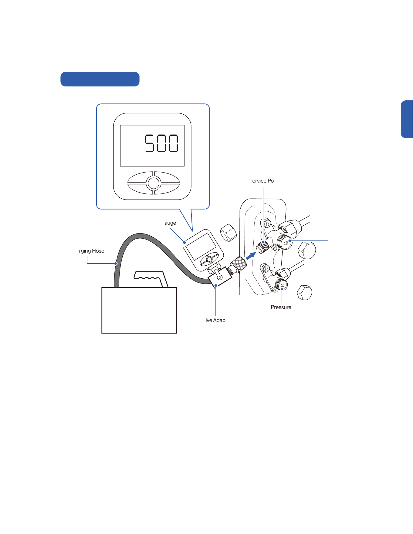
Vacuum Pumping, Leak Test (Using Micron Gauge) *RECOMMENDED, and Adjust Refrigernat Level
1. Remove the protective caps from the service port, low-pressure
valve (Lo·R), and high-pressure valve (Hi·R).
2. Connect the charging hose with a push pin to the service port.
3. Connect a the vacuum pump to the other end of the charging
hose and the micron gauge in between the service port and the
pump.
4. Open the valve adapter on the charging set, then turn on the
vacuum pump to vacuum the system.
5. Let the vacuum pump run until the micron gauge indicate the
value of 500 micron or lower. (ideally around 350 micron)
6. Close the valve adapter on the charging set and turn off the
vacuum pump.
7. Leave the system connected with the micron gauge for 5
minutes, then make sure the gauge indication does not exceed
500 micron.
NOTE: In the case of a leak, and the micron level increases above
500 micron, reconnect all the connection joints on the refrigerant
line, and redo the vacuum pumping.
8. Disconnect the pressure hose and the micron gauge from the
service port.
9. The air conditioner comes with enough refrigerant for the
standard length pipe set, add refrigerant charge if you use a
lengthened refrigerant line.
-00-
10. Turn on the air conditioner and confirm it can power on properly,
and then turn it off.
-00-
11. Fully open the low pressure valve (Lo·R) and high pressure valve
(Hi·R)
12. Put the protective caps back on the service, low-pressure valve,
and high-pressure valve.
13. Tighten the caps.
• Only add refrigerant if you use a lengthened refrigerant
line. There is no need to adjust or recover any amount
refrigerant if you use a standard or shortened refrigerant
line.
• Do not open the refrigerant valve before vacuum pumping.
• Stop and disconnect the vacuum pump from the system
before opening the refrigerant valve.
• Each indoor unit connected to the multizone outdoor unit
must vacuumed respectively.
Page 13
Page 52 / 62
• Additional Refrigerant Amount (ounce)
[0.11 × (Total Install length (ft) - 25)] oz
• Additional Refrigerant Amount (gram)
[10 × (Total Install length (m) - 7.5)] g
Additional Refrigerant
37
v.20251124U
Indoor and Outdoor Unit Installation
Charging Hose
Vacuum Pump
High Pressure Valve
(Hi·R)
Valve Adapter
Low Pressure Valve
(Lo·R)
Micron Gauge
Service Port
Micron
Micron Gauge Connection
Installation
38
Installation
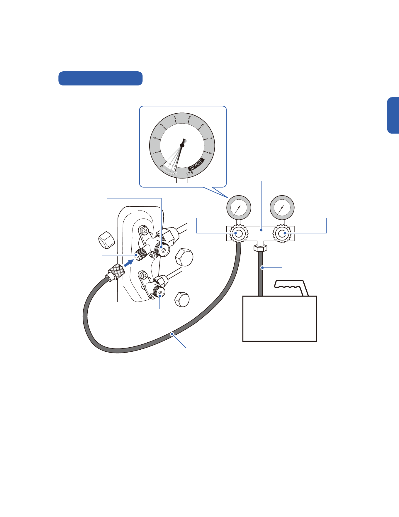
1. Remove the protective caps from the service port, low-pressure
valve (Lo·R), and high-pressure valve (Hi·R).
2. Connect the pressure hose with a push pin from the manifold
gauge to the service port.
3. Connect the charging hose from the manifold gauge to the
vacuum pump.
4. OPEN the low-pressure valve (Lo·M) and CLOSE the high
pressure valve (Hi·M) on the manifold gauge.
5. Turn on the vacuum pump to vacuum the system.
6. Let the vacuum pump run for at least 15 minutes and make sure
the gauge indicates −0.1 Mpa (−76 cmHg).
NOTE: Depending on your refrigerant line set length and vacuum
pump power, it might takes longer time.
7. Close the pressure valve (Lo·M) and turn off the vacuum pump.
8. Leave the system connected with the manifold gauge for 5
minutes, then make sure the gauge indication does not exceed
0.005 Mpa.
NOTE: In the case of a leak, and the pressure value increases,
reconnect all the connection joints on the refrigerant line, and
redo the vacuum pumping.
9. Open the high-pressure valve (Hi·R) for 1/4 turn, then close the
valve after 5 seconds.
10. Check all connection joints with refrigerant leak detector or liquid
leak detector.
11. The air conditioner comes with enough refrigerant for the
standard length pipe set, add refrigerant charge if you use a
lengthened refrigerant line.
-00-
12. Turn on the air conditioner and confirm it can power on properly,
and then turn it off.
-00-
13. Disconnect the pressure hose from the service port, then fully
open the low pressure valve (Lo·R) and high pressure valve (Hi·R).
14. Put the protective caps back on the service, low-pressure valve,
and high-pressure valve.
15. Tighten the caps.
• Only add refrigerant if you use a lengthened refrigerant
line. There is no need to adjust or recover any amount
refrigerant if you use a standard or shortened refrigerant
line.
• Do not open the refrigerant valve before vacuum pumping.
• Stop and disconnect the vacuum pump from the system
before opening the refrigerant valve.
• Each indoor unit connected to the multizone outdoor unit
must vacuumed respectively.
• Analog manifold gauge is less accurate and measure vacuum at a lower resolution than a digital micron gauge. DELLA recommend
using micron gauge for vacuum pumping mentioned on -00-
Page 36
Indoor and Outdoor Unit Installation
Vacuum Pumping, Leak Test (Using Manifold Gauge), and Adjust Refrigernat Level
Wait 5 sec
• Additional Refrigerant Amount (ounce)
[0.11 × (Total Install length (ft) - 25)] oz
• Additional Refrigerant Amount (gram)
[10 × (Total Install length (m) - 7.5)] g
Additional Refrigerant
Page 13
Page 52 / 62
39
v.20251124U
Indoor and Outdoor Unit Installation
kg/cm²
Manifold Gauge Connection
Pressure Hose
Charging Hose
Manifold Gauge
High Pressure Valve
(Hi·R)
High Pressure Valve
(Hi·M)
Low Pressure Valve
(Lo·R)
Low Pressure Valve
(Lo·M)
Service Port
Vacuum Pump
Installation
40
Installation
Thermostat Installation
Specification
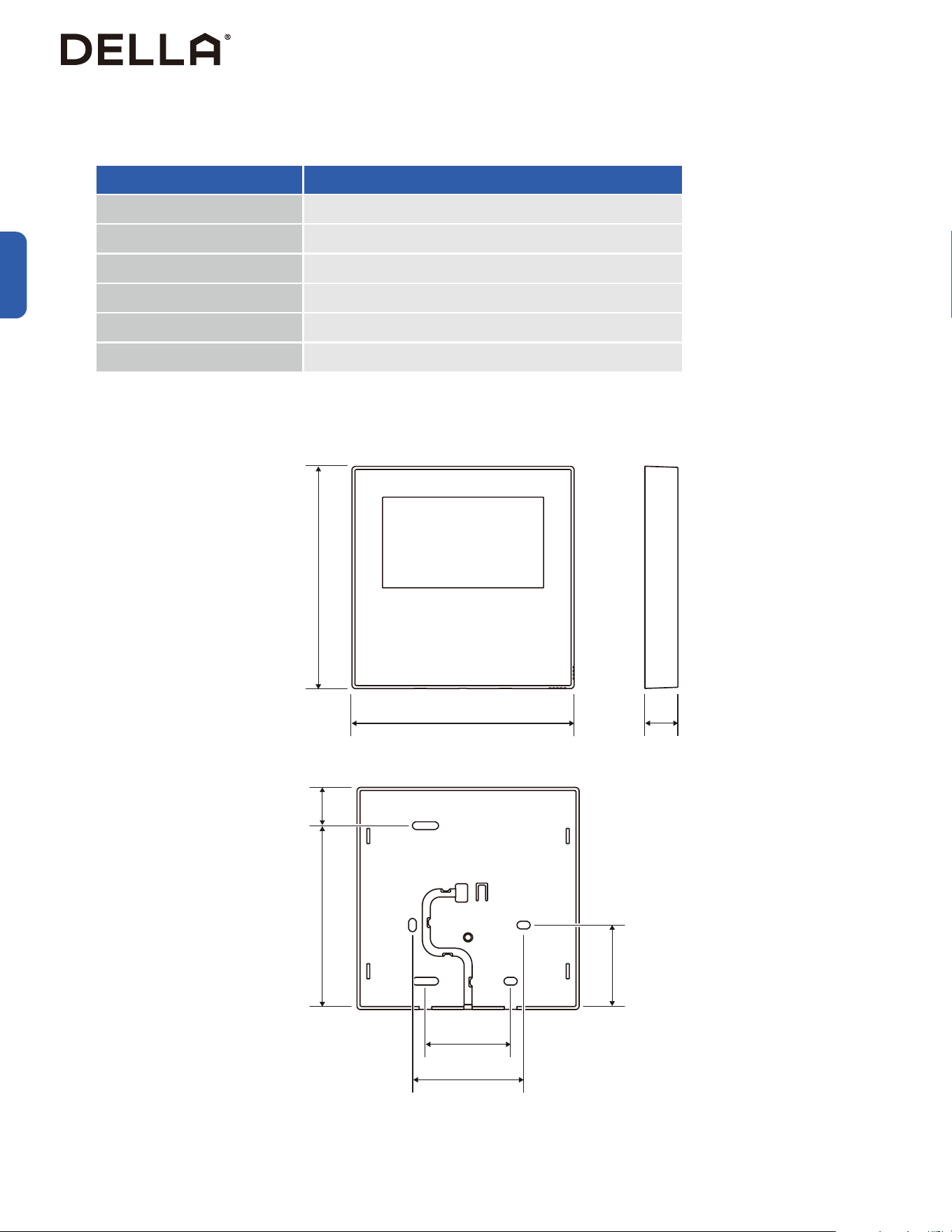
Dimension
048-T-CTRL
Input Voltage DC 5V / 12V
Ambient Temperature Range 23°F - 110°F / -5°C - 43°C
Ambient Humidity Range RH 40% - RH 90%
Wire Type Shielded vinyl cord / cable
Wire Size 0.5 - 1.25mm²
Wire Length 49ft / 15m
4.7" / 120mm
0.71" / 18mm
1.81" / 46.1mm
2.36" / 60mm
1.73" / 44mm
3.31" / 84mm
0.81" / 20.6mm
4.7" / 120mm
41
v.20251124U
Thermostat Installation
Installation
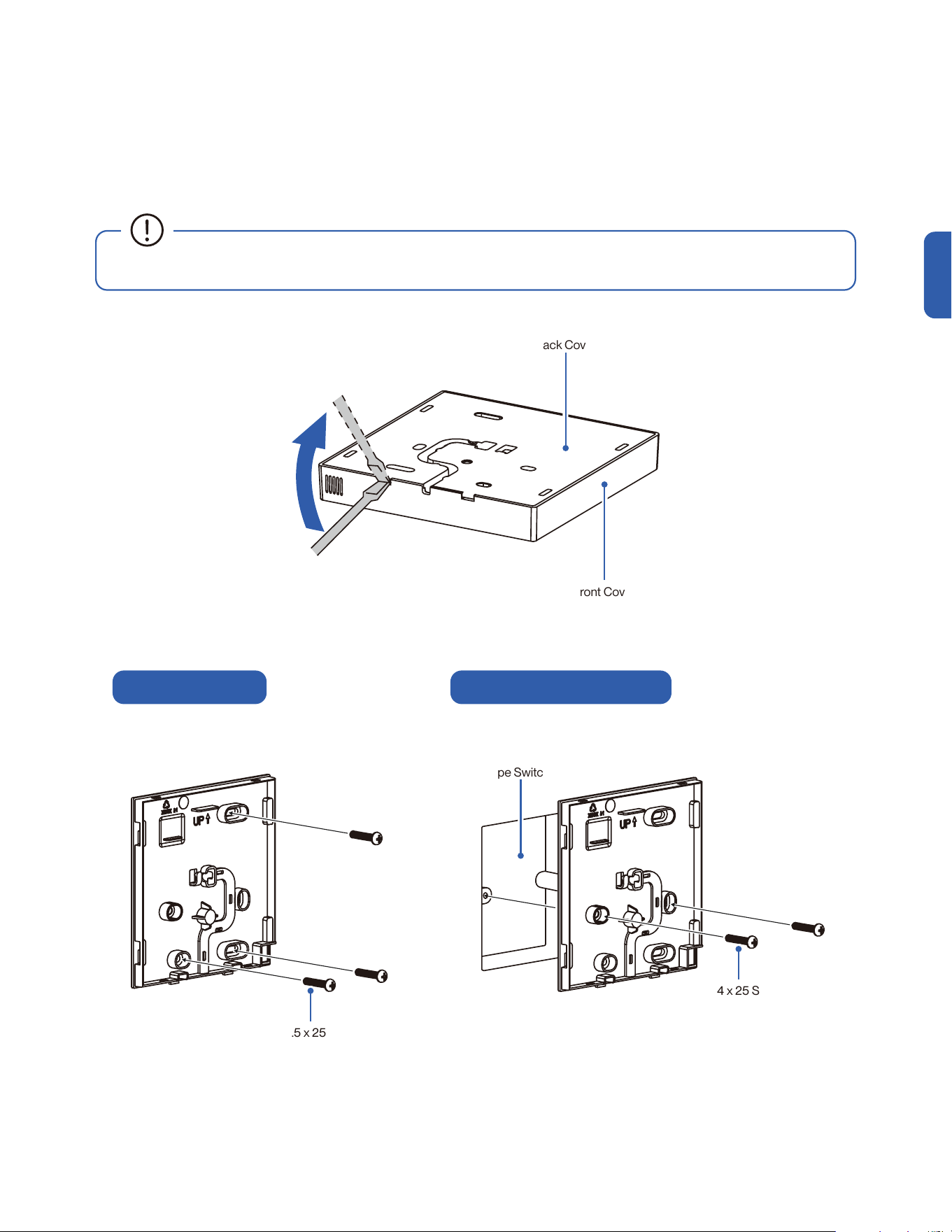
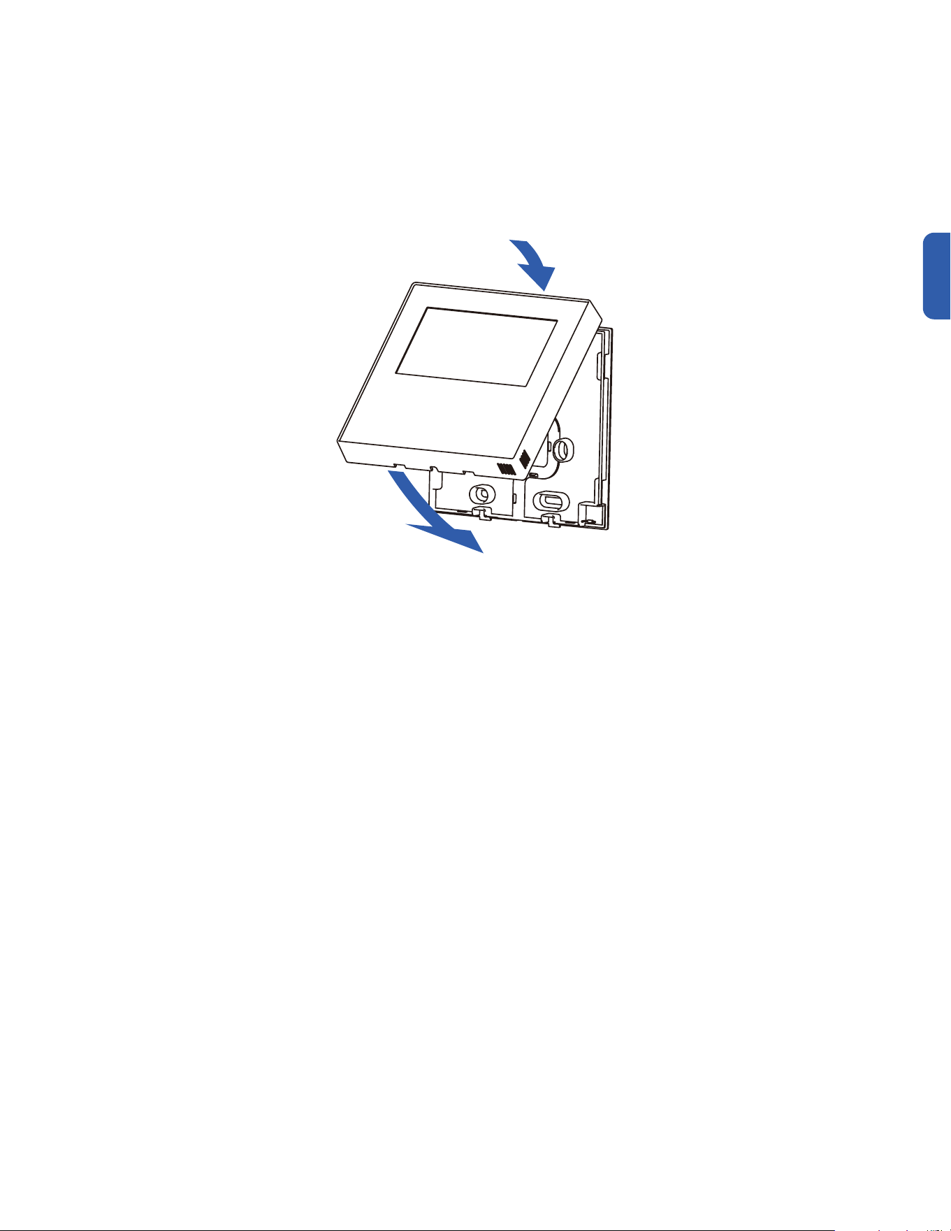
1. Use a flathead screwdriver to gently pry apart the back cover and the front cover.
2. Mount the back cover of the thermostat directly on the wall or on a 86 type (86mm x 86mm) switch box.
Mounting the Thermostat
M3.5 x 25 Screw
M4 x 25 Screw
Mounting on Wall Mounting on 86 Type Switch Box
• Be careful when pry open the two halves and not damage the PCB on the front cover.
Back Cover
Front Cover
86 Type Switch Box
42
Installation
Thermostat Installation
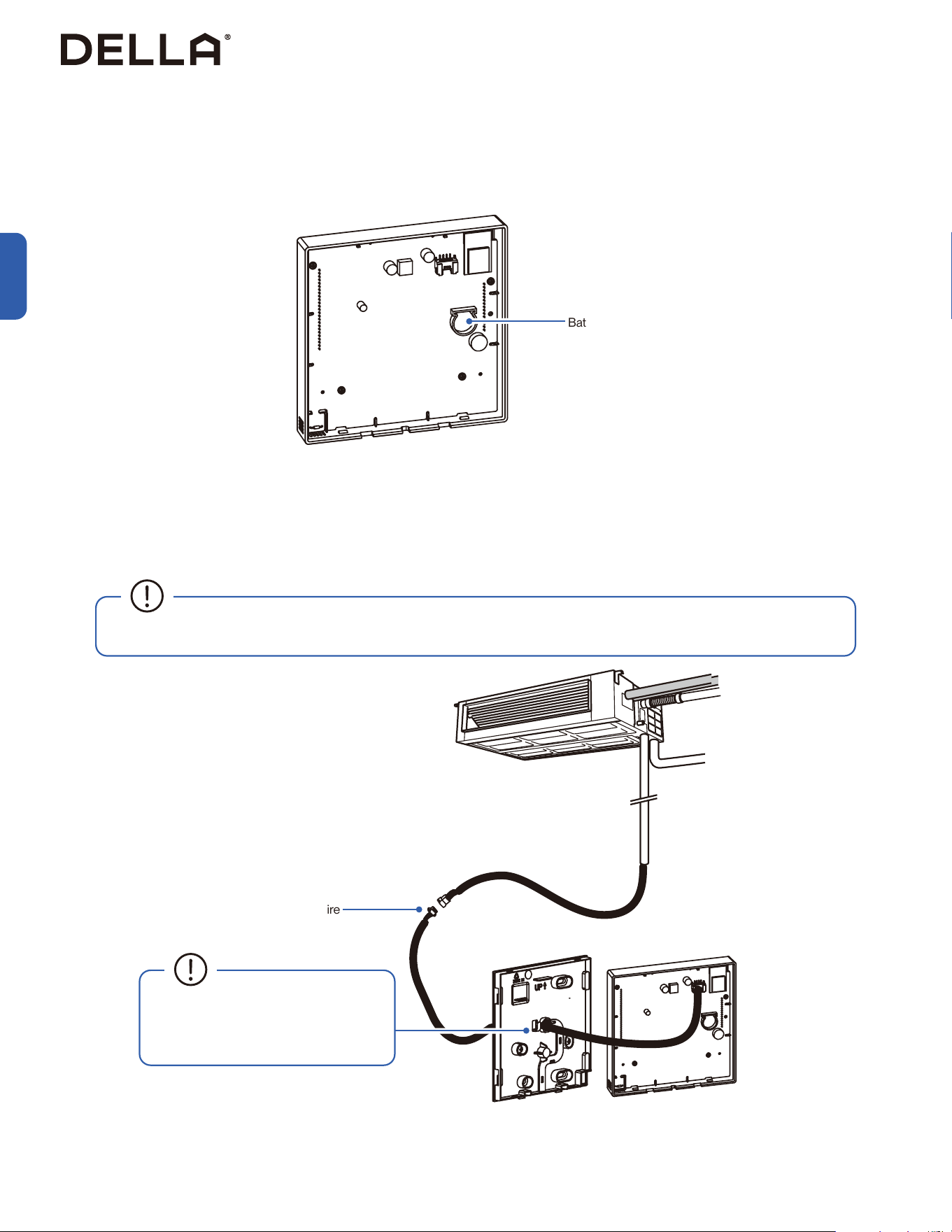
• Backup battery can be installed into the thermostat's battery compartment.
• Backup batter provides power to the thermostat in case of power failure to ensure time keeping.
1. Connect the wire control cable from the indoor unit to the thermostat.
2. Seal the gap between the wire and the opening on the thermostat's back cover with putty to prevent moisture, water, or insect from getting
into the thermostat.
Backup Battery (Optional)
Wiring
• The conection lug at the end of the shielded wire should be properly grounded.
Battery Compartment
4-core Wire
• Seal the gap with putty to prevent
moisture, water, or insect from getting
into the thermostat.
43
v.20251124U
Installation
Thermostat Installation
1
2
1. Arrange the wire between the front and back cover.
2. Reattach the front cover to the back cover. Make sure the cover click into place.
Mounting the Thermostat
44
Finishing
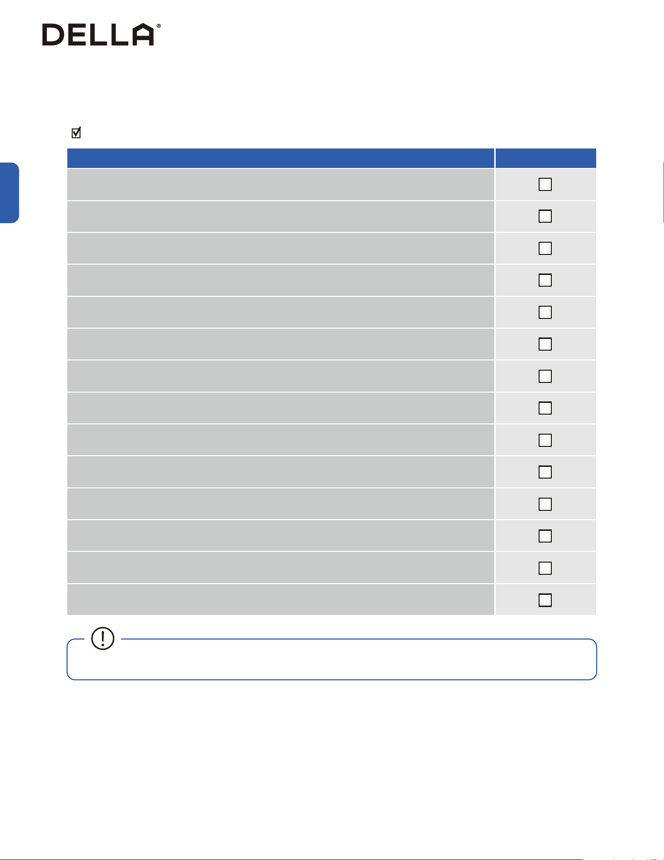
Check List
Go through the following list and check your installation.
the check box for each conrmation.
Check List Status
Are the indoor and outdoor unit kept at least the minimum distance away from the closest wall and obstacle?
Is the indoor securely mounted?
Is the drain hose properly attached?
Are the refrigerant pipes securely connected and no refrigerant leakage?
Are all drain hose and refrigerant pipes properly insulated?
Is the system properly vacuumed?
Is all the wall opening sealed o?
Are the refrigerant valves fully opened?
Do the power supply and voltage match the unit rating?
(Check before connecting to power supply)
Is the electrical wiring in the unit connected and secured?
Are the units properly grounded?
Is the power breaker, fuse, or protection device installed?
Is the thermostat connected and can it send control commands to the air conditioner?
Can the remote control send control commands to the air conditioner?
• Any failures, accidents, or damages caused by improper installation are not covered by the warranty.
Installation
45
v.20251124U
Installation
Test Run
After the installation, test run the mini split system and take sure it performs and works properly without water leak or abnormal noise.
Finishing
1. Turn on the power supply.
2. Turn on the air conditioner using the remote control / thermostat.
3. Perform a drain test -00-
4. Test the unit at the lowest temperature in COOL mode.
5. Test the unit at the highest temperature in HEAT mode.
6. Test each mode for at least 8 minutes.
- Measure the air temperature at the air outlet.
- Check if water drains properly from the drainage hose.
- Check if the louver and deflectors move properly.
7. If everything is operating normally, return to normal setting and turn off the air conditioner.
8. Inform the user to read the operation instruction before use, and demonstrate to the user how to use the air conditioner, the necessary
knowledge of service and maintenance, and a reminder of accessories storage.
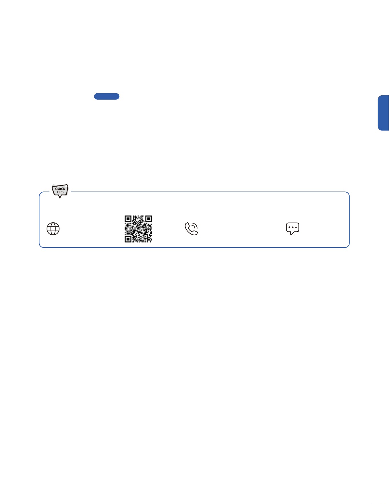
Contact us if you encounter any problems during or after the installation.
support.dellahome.com
24/7 Live Chat
800-863-4143
6:00 a.m. - 4:00 p.m. PST
Monday - Friday
Page 22
46
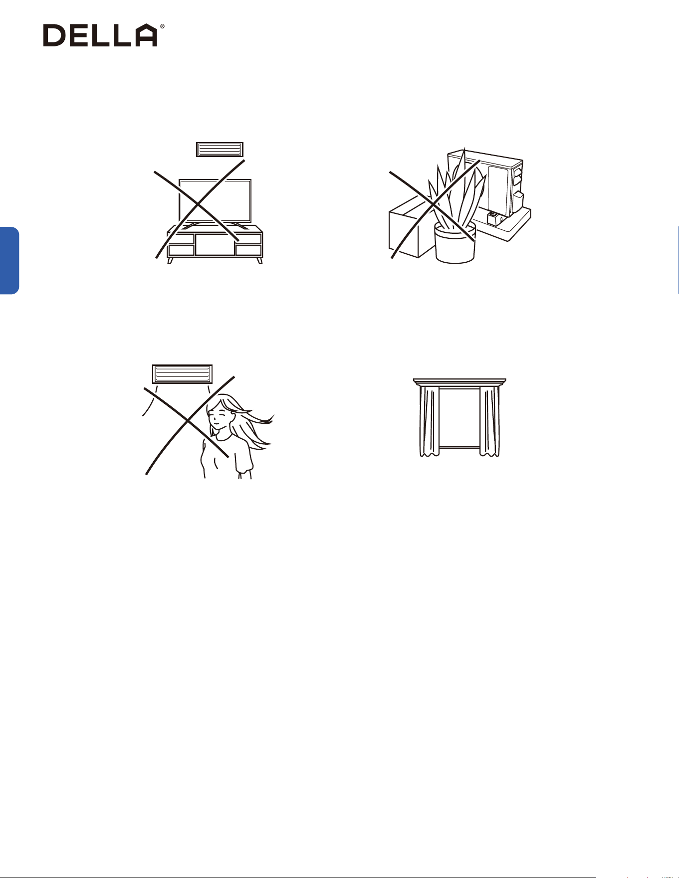
Operation Tips
Before Using
Avoid placing TV, radio or large furniture next to the air
conditioner.
Avoid putting plants or objects around the outdoor unit.
Close windows and blinds.Avoid direct wind flow to people, pets, or plants.
• It may block wind flow or interfere with the remote control. • It may lower the air conditioner efficiency or cause malfunction.
• The air conditioner can cool or warm the area with better
efficiency.
• Expose to direct wind flow for extended period of time may
have a negative impact on your health.
Before Using
47
v.20251124U
Before Using
Before Using
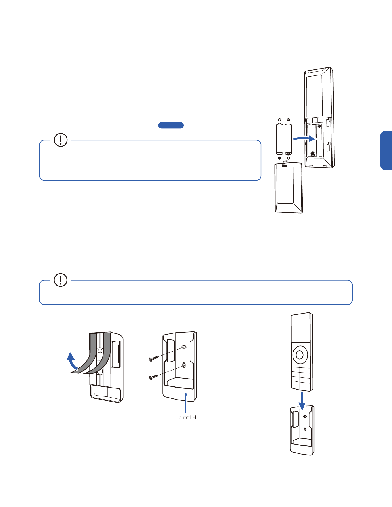
Remote Control Holder
Remote Control (Inserting Battery)
Remote Control (Remote Control Holder)
1. Attach the remote control holder to a wall by using the double sided adhesive tape or provided screws.
NOTE: Wall anchor might needed if you install it on a dry wall.
2. Insert the remote control into the holder.
• After new batteries are inserted into the remote control, the display screen will lights up for 3
seconds. Leave it for 10 seconds, the display will automatically turn off.
• The default temperature unit will automatically turn into degree Fahrenheit.
To change temperature unit, follow instruction on -00- . .
• Do not use rechargeable batteries.
• Replace the old batteries with new ones of the same type.
• Do not dispose batteries as unsorted municipal waste.
• Avoid exposing the remote control to direct sunlight.
Page 59
1. Push and slide the back cover off the remote control.
2. Insert 2 LR03 AAA 1.5 v batteries into the battery compartment.
3. Reinstall the back cover to the remote control.
48

49
v.20251124U
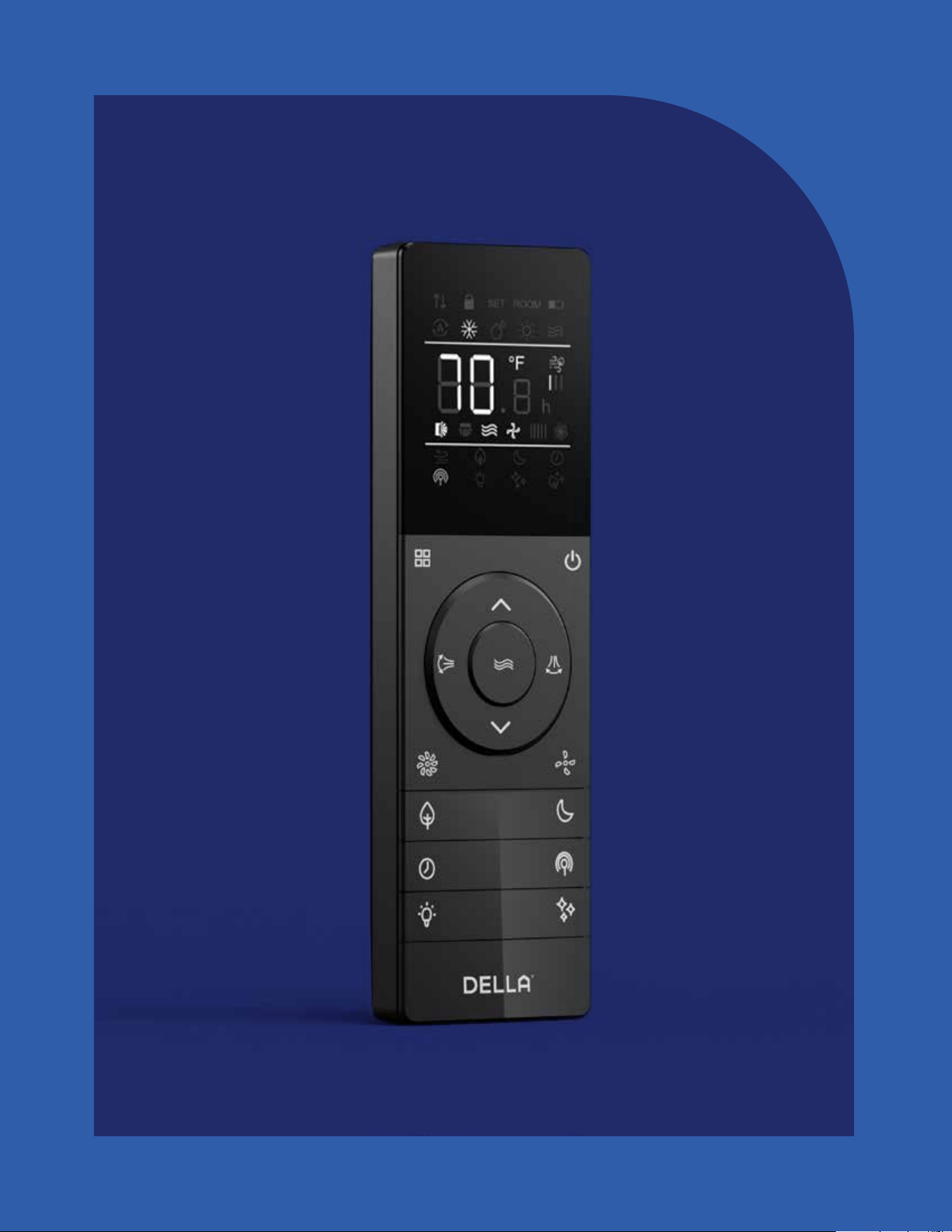
Made to live with you, Della puts controls in your
hands so that you can easily dail in a stress-free
space that helps you feel more you.
Just Right,
Always.
50
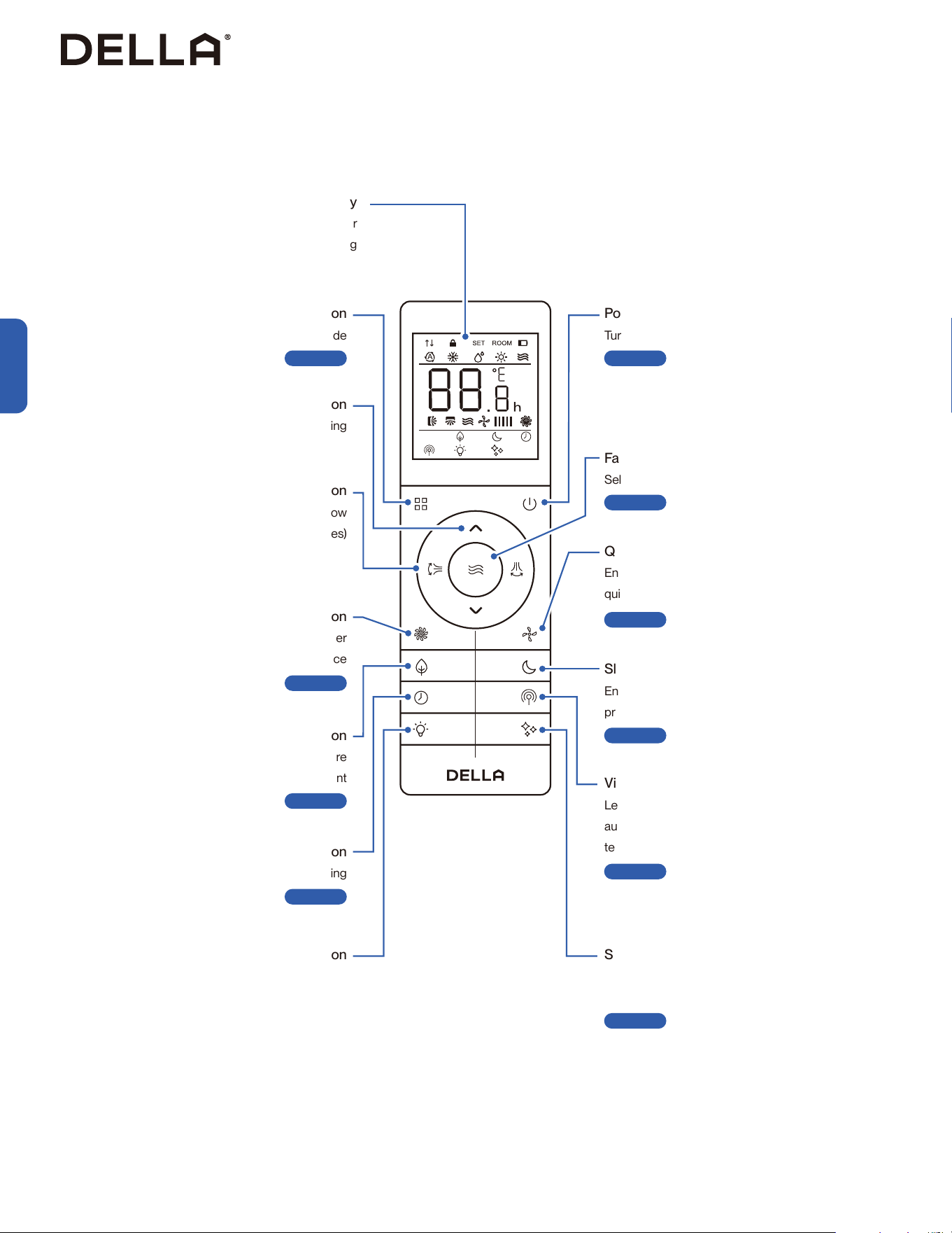
Vicinity Sensor Button
Let the air conditioner adjust temperature
automatically according to the detected
temperature around the remote control
-00-
Self Clean Button
Enable the air conditioner to clean its internal
parts
-00-
Display
Indicate operating status, temperature or
timer setting
Mode Button
Select operation mode
-00-
Power Button
Turn ON / OFF the air conditioner
-00-
Fan Button
Select fan speed
-00-
Quiet Button
Enable the air conditioner to run in
quiet mode
-00-
Sleep Button
Enable the air conditioner to operate a pre-set
program suited for sleep time
-00-
Increase / Decrease Button
Adjust temperature / timer setting
Air Flow Button
Control deflector & flaps to direct air flow
(Not functional for 048-DC series)
Turbo Button
Temporary boosting the air conditioner
performance
-00-
ECO Button
Enable the air conditioner to be more
energy efficient
-00-
Display Button
Turn ON / OFF the indoor unit display
(Not functional for 048-DC series)
Timer Button
Enable ON / OFF timer setting
-00-
Remote Control
Before Using
Before Using
Page 52
Page 54
Page 55
Page 56
Page 52
Page 53
Page 54
Page 55
Page 57
Page 58
51
v.20251124U
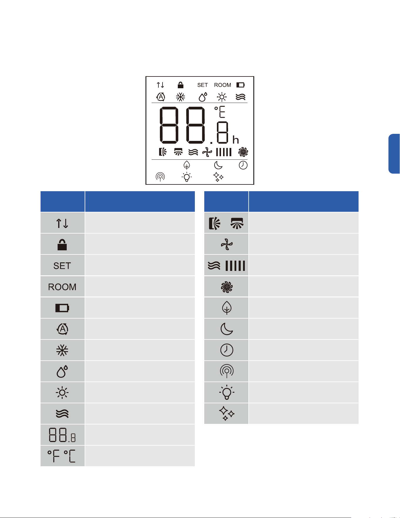
Before Using
Remote Control
Before Using
LED Indicator Function
Signal Indicator
Child Lock
Indicate Set Temperature
Indicate Room Temperature
Low Battery
Auto Mode
Cool Mode
Dehumidify Mode
Heat Mode
Fan Mode
Indicate Temperature Value
Temperature Unit
Degree Fahrenheit / Celsius
LED Indicator Function
Horizontal & Vertical Air Flow Indicator
(Not functional for 048-DC series)
Quiet Mode
Fan Speed
Turbo Mode
Eco Mode
Sleep Mode
Timer
Vicinity Sensor Mode
Indoor Unit Display Indicator
(Not functional for 048-DC series)
Self Clean
52
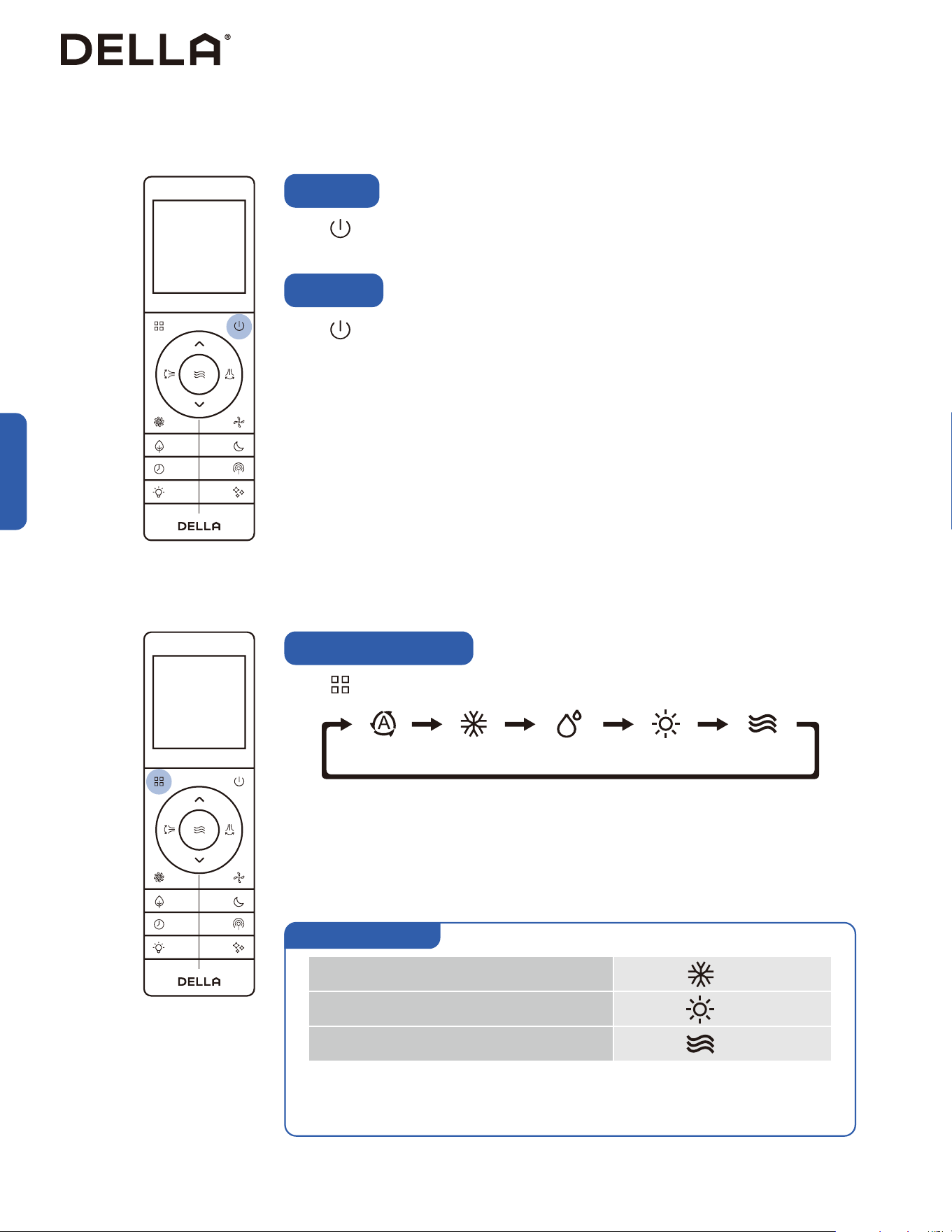
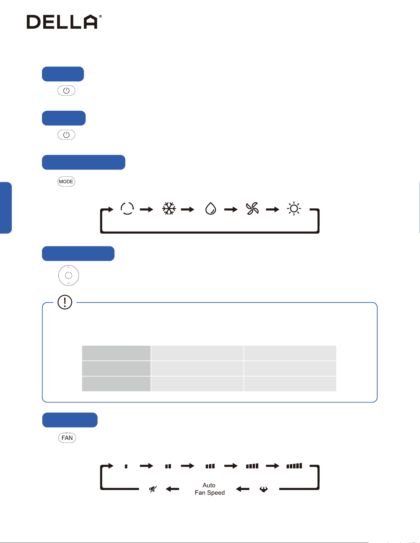
Basic Operation
Press .
• The air conditioner will start operating.
Press .
• The air conditioner will stop operating.
Power ON
Power OFF
Basic Operation
• It may takes a few minutes for the air conditioner to switch between modes.
• During Heat mode, the air conditioner can automatically activate defrost cycle, which is essential
to remove frost on the condenser for heat exchange function. This procedure usually last for 2 - 10
minutes. When defrosting, indoor unit fan will stop operating. Once defrosting is completed, it will
resume heat mode automatically.
• Auto mode allows the AC to automatically select operation mode based on the above logic.
• Each mode will operate for at least 6 minutes before switching.
• Auto mode does not support sleep mode and eco mode operation.
Auto Cool Dehumidify Heat Fan
Press to select operation mode.
Select Operation Mode
Set temp. < Room temp.
Set temp. > Room temp.
Set temp. = Room temp. ± 1.8°F / 1°C
Cool
Heat
Fan
Auto mode operation
53
v.20251124U
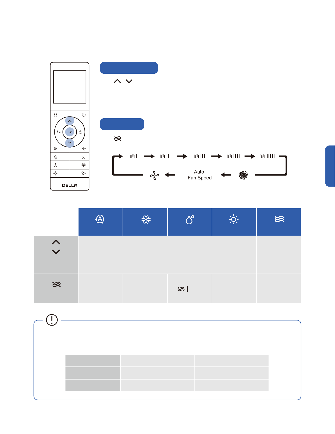
Basic Operation
Basic Operation
Adjust Temperature
Set Fan Speed
Press to adjust temperature setting .
• Temperature setting will adjust by 1°F / 1°C increment for each time the button is pressed.
• Press and hold the buttons to adjust temperature continuously.
• Temperature can only be set between 61°F - 88°F / 16°C - 31°C.
Press to select your desired fan speed.
61°F - 88°F / 16°C - 31°C N/A
All Fan Speed All Fan Speed All Fan Speed All Fan Speed
Auto
Cool
Dehumidify
Temperature
Setting
Fan Speed
only
Heat
Fan
Indoor Temperature Outdoor Temperature
Cool / Dehumidify Mode 63°F - 90°F / 17°C - 32°C 5°F - 131°F / -15°C - 55°C
Heat Mode 32°F - 80°F / 0°C - 27°C -13°F - 86°F / -25°C - 30°C
• The AC performs the best within operational ambient temperature.
• When the ambient temperature is too high, the AC may trip the circuit breaker protection and cause the system to shut down.
• When the ambient temperature is too low, the AC may generate excessive moisture, leading to water dripping from the outdoor unit.
54
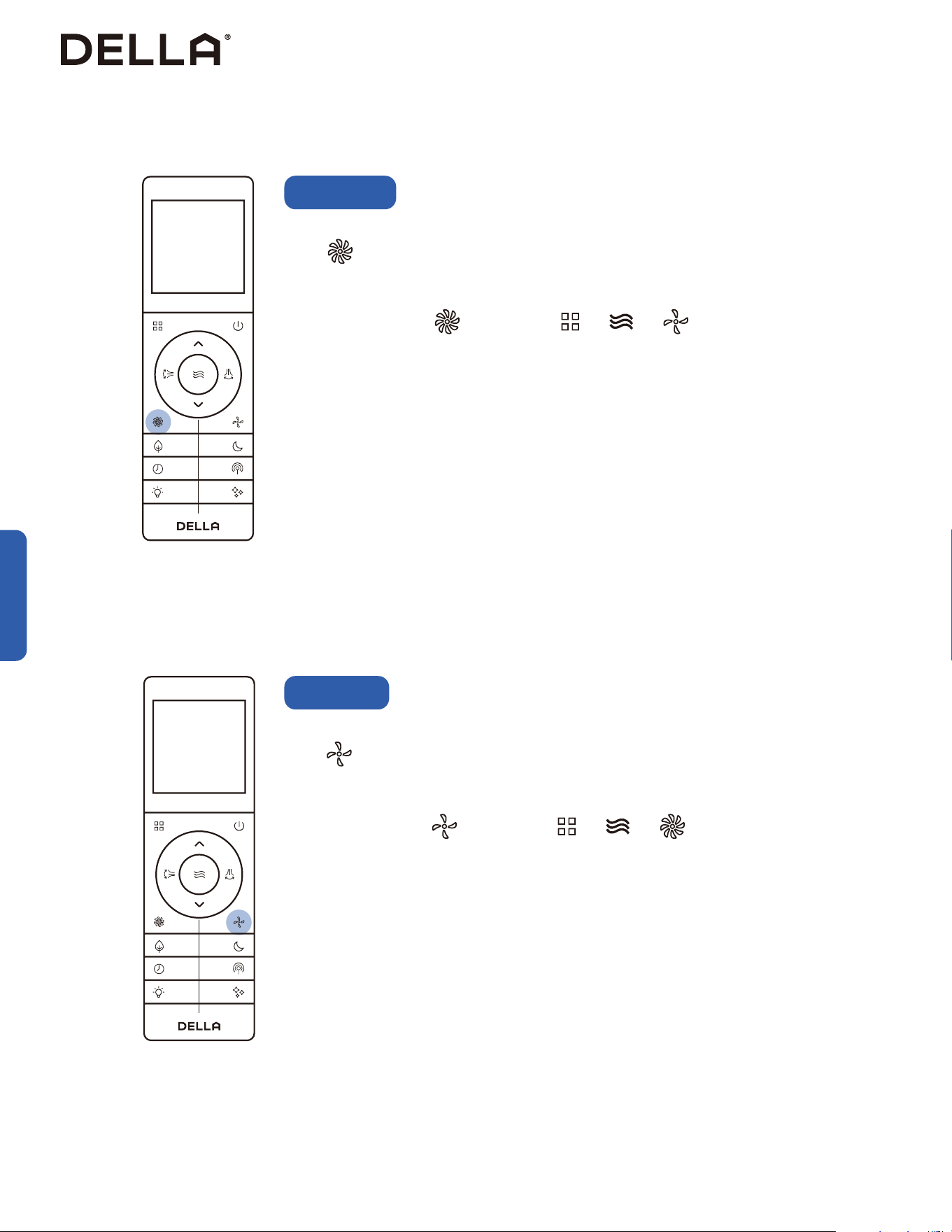
Advance Function
Turbo Mode
Using turbo mode can boost the air conditioner performance in a short amount of time.
Press .
• The air conditioner will operate in boosted fan speed.
• Turbo mode is not available when the air conditioner is operating in dehumidification mode.
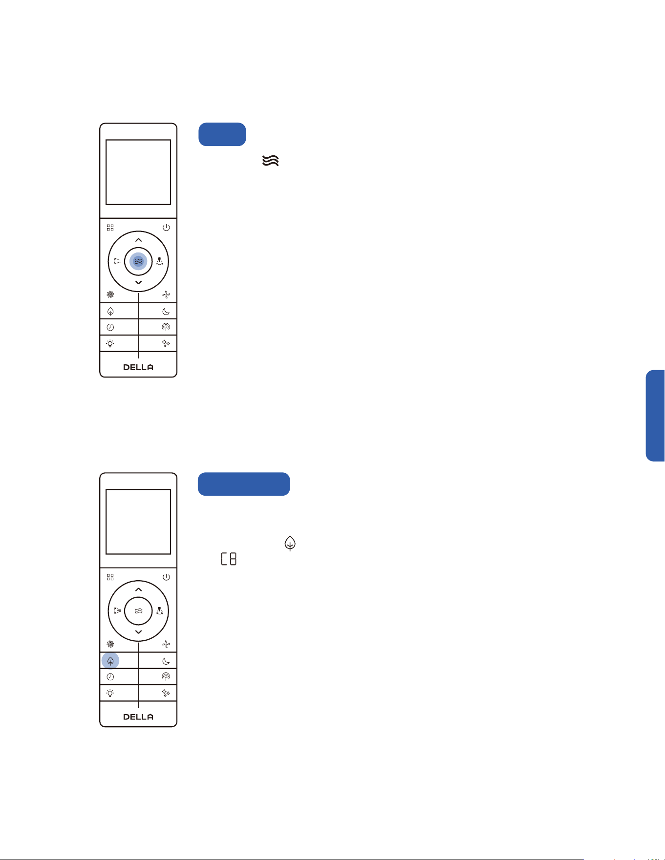
The air conditioner will operate at the minimum noise level under quiet mode.
Press .
• The air conditioner will operate in the lowest fan speed.
• Quiet mode is not available when the air conditioner is operating in dehumidification mode.
To stop turbo mode, press again or press / / .
To stop quiet mode, press again or press / / .
Quiet Mode
Advance Function
55
v.20251124U
Advance Function
+ +
79°F - 88°F / 26°C - 31°C 61°F - 77°F / 16°C - 25°C
Advance Function
CoolECO
ECO
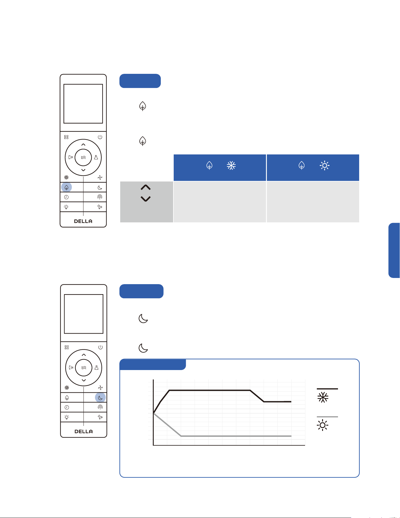
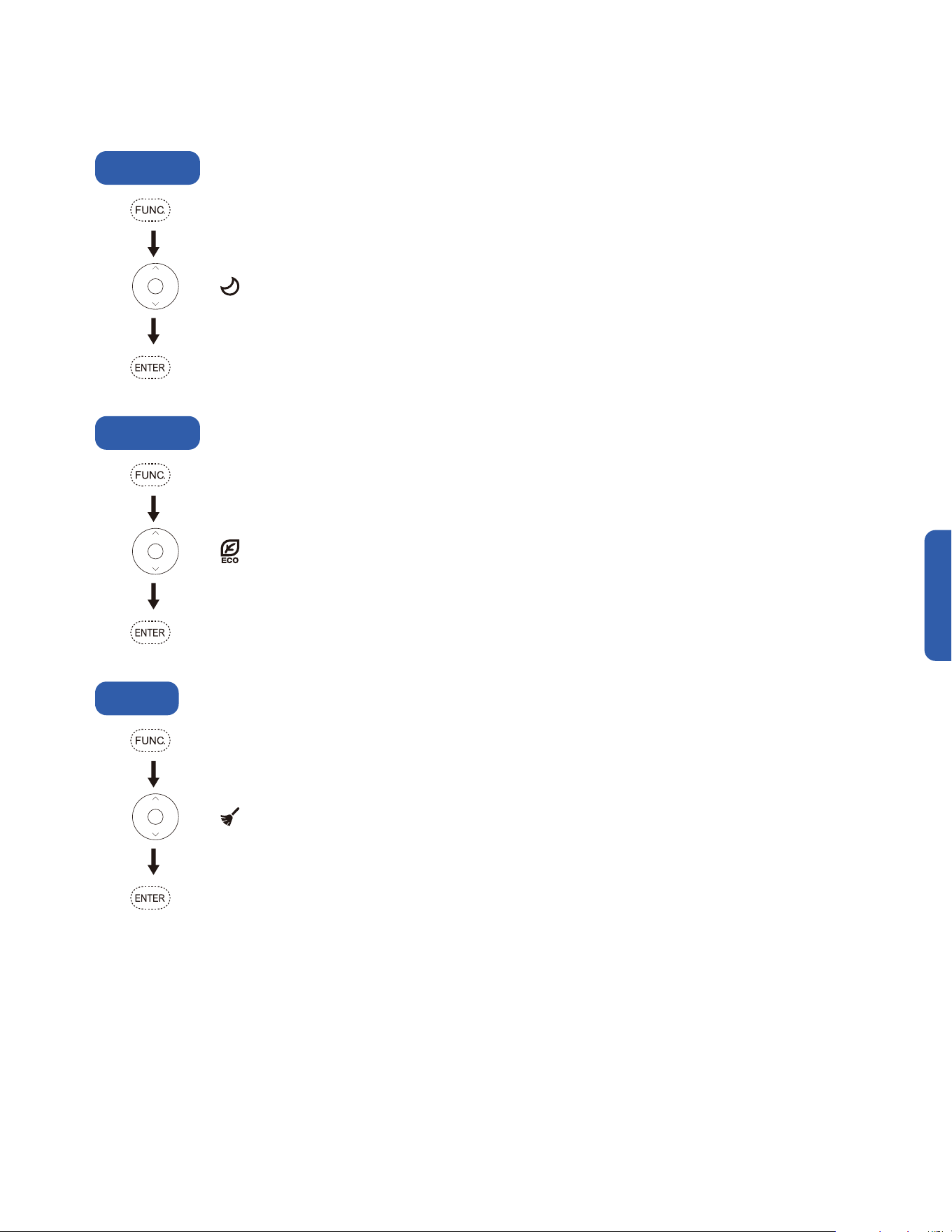
ECO Mode
The air conditioner will operate with maximum energy efficiency.
Press .
• ECO mode is only available when the air conditioner is operating in cool or heat mode.
• The set temperature for cool mode and heat mode will be limited.
Press again or set the temperature beyond the ECO mode limit to cancel ECO mode.
Heat
Temperature
Setting
In sleep mode, the air conditioner will operate a pre-set program which is suitable during sleep.
Press .
• Sleep mode will operate for 10 hours and then switch back to previously set mode.
• Sleep mode is not available when the air conditioner is operating in auto, dehumidify or fan mode.
Press again to stop sleep mode.
Sleep Mode
75°F
70°F
80°F
0 1 2 3 4 5 6 7 8 9 10
Hour
Temp.
Sleep mode operation
Cool
Heat
NOTE: This graph is for informational reference only. The actual product may changes temperature at a different
rate depending on the initial set temperature in sleep mode.
56
• While entering the setting, make sure to press the button within 5 seconds after the previous button was pressed. otherwise, the
entire process will reset and you will have to start over.
•
Advance Function
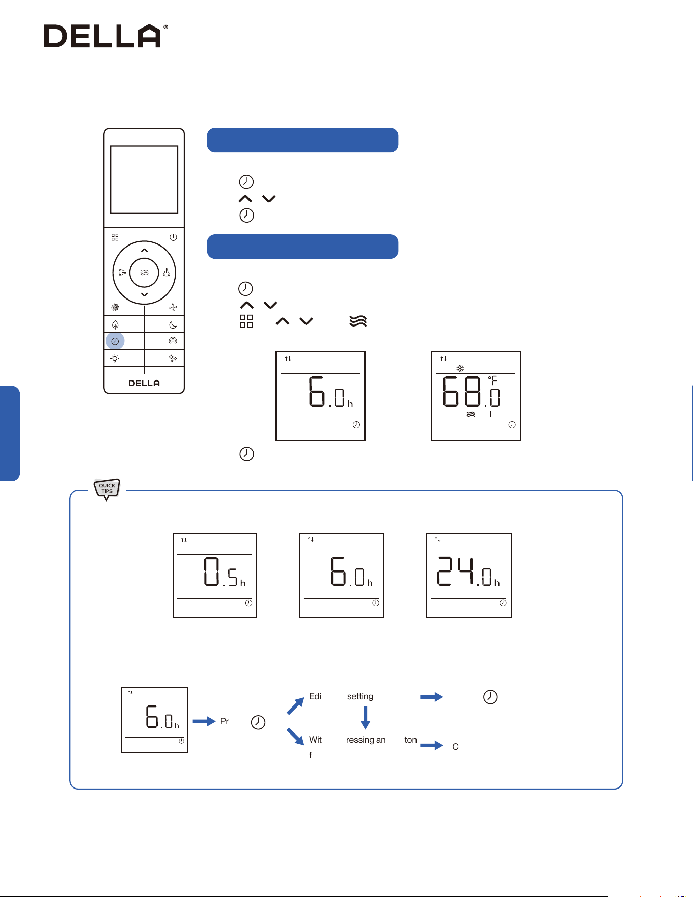
Timer Function (Shutdown Timer)
Timer Function (Start-up Timer)
Set a timer to automatically turn OFF the air conditioner.
Press when the air conditioner is ON.
Press to set the desired turn off time.
Press to confirm the timer setting.
Press to confirm the timer setting.
Set a timer to automatically turn ON the air conditioner.
Press when the air conditioner is OFF.
Press to set the desired turn on time.
Press , and to select your desired operation mode, temperature setting, and
fan speed for when the air conditioner is turn ON.
Press
Timer default at 6 h
Timer Set
Edit timer setting
Cancel timer
Without pressing any button
for 5 sec
Press to confirm
• Both the shutdown and start-up timer can be set between 0.5 - 24 hours.
Advance Function

57
v.20251124U
• Both the remote control and the wall mounted thermostat supports vicinity sensor function.
• When the vicinity sensor function is enabled on the remote control, the AC will use the remote’s
sensor data; if it is enabled on the wall mounted thermostat, it will use the wall mounted
thermostat’s data. The AC will follows the last operated device for temperature adjustment.
Advance Function
Advance Function
Vicinity Sensor
Vicinity sensor function turns your remote control into a portable thermostat that automatically controls the
unit to adjust the temperature of the room you are in.
Press to activate vicinity sensor function.
• In the case of the temperature detected by the remote control and the indoor unit thermostathas has
a difference greater than 11 °F / 6 °C, the AC would use the temperature data from the indoor unit for
temperature adjustment, instead of that from the remote control.
Remote control detect its surrounding
temperature every 3 minutes for 8 hours.
Air conditioner would operate to match the
detected temperature to the set temperature.
NOTE: The remote control must be pointed towards the thermostat display to prevent lost of communication.
Press again to stop vicinity sensor function.
58
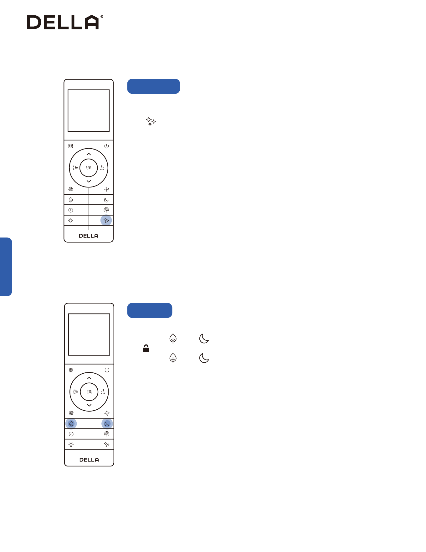
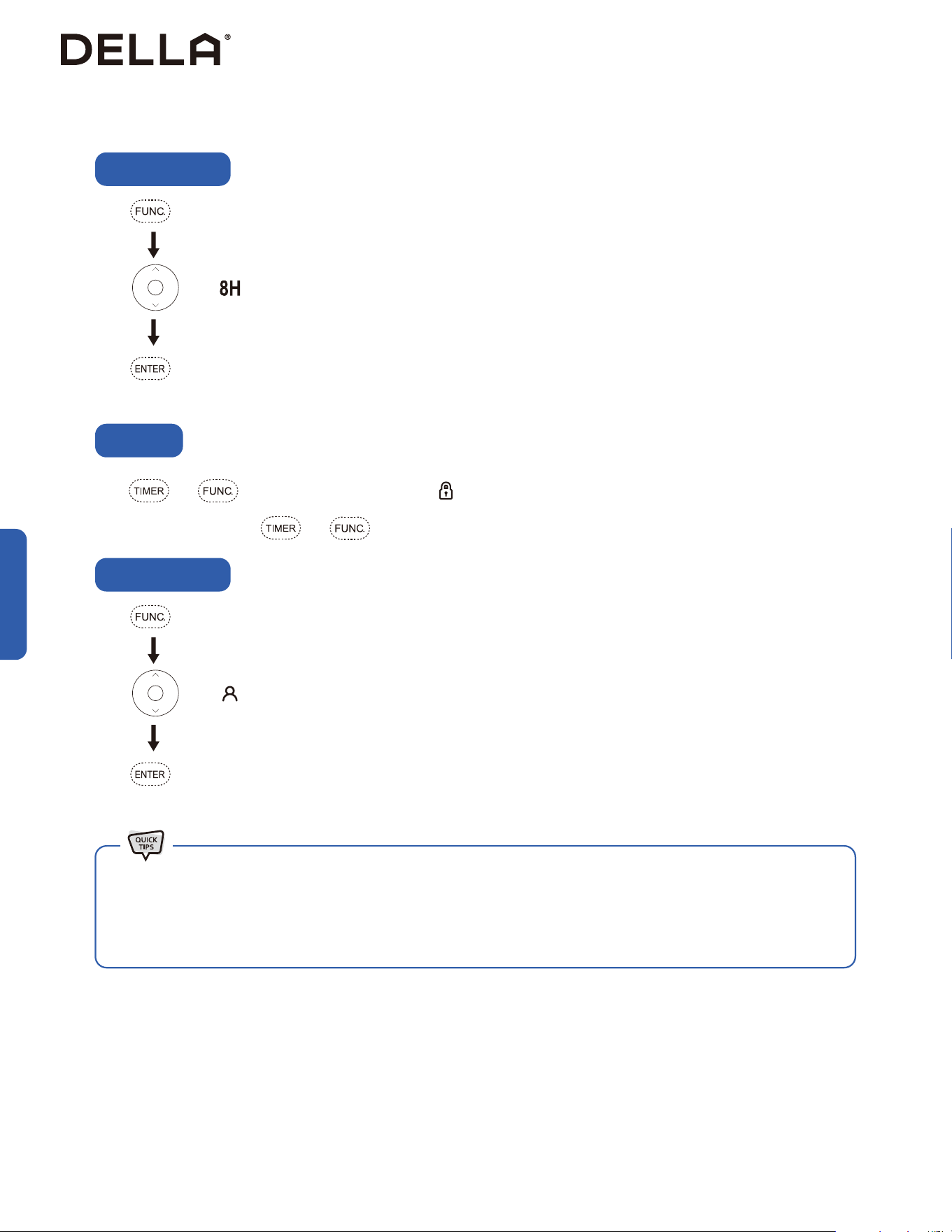
Advance Function
Child lock function will disable all input from the remote control until unlocked.
Press and hold and for 3 seconds to activate child lock.
• will display on the remote control display.
Press and hold and for 3 seconds again to dectivate child lock.
Child Lock
Advance Function
Self cleaning function allows the air conditioner to clean the interior parts and helps carry away the
accumulated dirt, bacteria, etc. from the indoor evaporator.
Press when the air conditioner is OFF.
• The self cleaning function will run for 30 minutes, then it will return to the previously operating mode
once it is finish.
• It is recommended to operate this function when the indoor ambient temperature is under 86°F / 30°C,
and the outdoor ambient temperature is between 41°F - 86°F / 5°C - 30°C.
• It is suggested to run the self cleaning function once every 3 months.
• It is normal that the unit makes some noise during self cleaning process as plastic materials expand and
contract with temperature change.
Self Cleaning
59
v.20251124U
Advance Function
Press and hold for 5 seconds.
• The temperature unit will switch between °F and °C.
Advance Function
°F / °C
To maximize heat efficiency, you can force the outdoor unit to perform a defrost cycle before using heat
mode.
In heat mode, press 10 times within 8 seconds.
• code will display on the indoor unit, and the AC will enter defrost cycle.
During the defrost cycle, your indoor unit will blow cold air temporarily.
Once the defrost cycle ends, the AC will automatically resume heat mode operation.
Forced Defrost
60
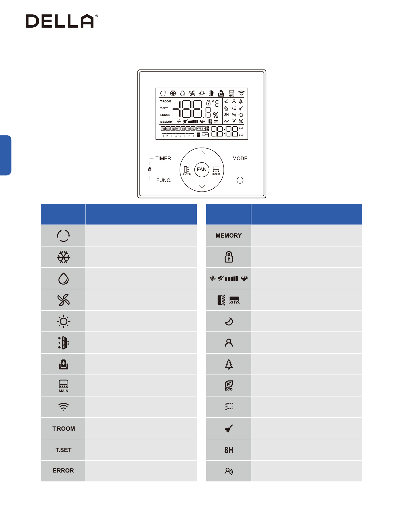
Before Using
Before Using
Thermostat Display
LED Indicator Function
Auto Mode
Cool Mode
Dry Mode
Fan Mode
Heat Mode
Dirty Filter Indicator
Door Card Indicator
(Not functional for 048-DC series)
Main IDU
(Not functional for 048-DC series)
Wi-Fi Indicator
Display Showing Room Temperature
Display Showing Set Temperature
Display Showing Error Code
LED Indicator Function
Power Down Memory
Child Lock Indicator
Fan Speed Indicator
Horizontal & Vertical Air Flow Indicator
(Not functional for 048-DC series)
Sleep Mode
Vicinity Sensor Mode
Health Function
Eco Mode
Gentle Air Mode
Self Clean
8-Degree Heating Function
Voice Command
ON
OFF
61
v.20251124U
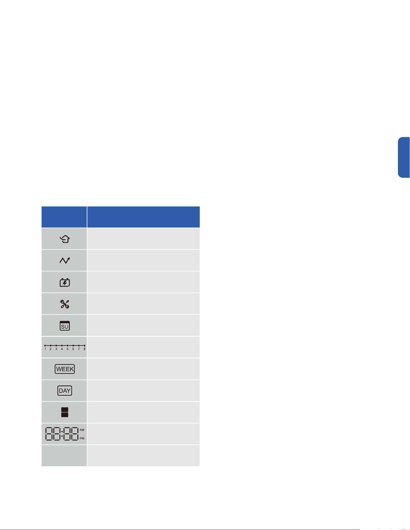
Before Using
Before Using
Thermostat Display
LED Indicator Function
Fresh Air Circulation
Auxiliary Heat
(Not functional for 048-DC series)
Generator Function
(Not functional for 048-DC series)
Parameter Setting
Indicating Week Day Timer Set
Indicating Hour Timer Set
Indicating Week Timer
Indicating Day Timer
Timer ON / OFF Indicator
Clock
ON
OFF
62
Basic Operation
Power ON
Basic Operation
Press .
• The air conditioner will turn on.
Press .
• The air conditioner will stop operating.
Press to adjust temperature setting.
Press to select operation mode.
Power OFF
Select Operation Mode
Auto Cool Dry HeatFan
Adjust Temperature
Set Fan Speed
Press to select your desired fan speed.
Indoor Temperature Outdoor Temperature
Cool / Dehumidify Mode 63°F - 90°F / 17°C - 32°C 5°F - 131°F / -15°C - 55°C
Heat Mode 32°F - 80°F / 0°C - 27°C -13°F - 86°F / -25°C - 30°C
• The AC performs the best within operational ambient temperature.
• When the ambient temperature is too high, the AC may trip the circuit breaker protection and cause the system to shut down.
• When the ambient temperature is too low, the AC may generate excessive moisture, leading to water dripping from the outdoor unit.
63
v.20251124U
• The air conditioner will operate in a pre-set program which is suitable during sleep.
• The air conditioner will operate with maximum energy efficiency.
Press .
Press .
Press to confirm the selected mode / function.
Press to confirm the selected mode / function.
Press until blinks.
Press until blinks.
Sleep Mode
Eco Mode
Advance Function
Advance Function
• The air conditioner will start self cleaning function.
Press .
Press to confirm the selected mode / function.
Press until blinks.
Self Clean
Self cleaning function allows the air conditioner to clean the interior parts and helps carry away the
accumulated dirt, bacteria, etc. from the indoor evaporator.
• The self cleaning function will run for 30 minutes, then it will return to the previously operating mode
once it is finish.
• It is recommended to operate this function when the indoor ambient temperature is under 86°F / 30°C,
and the outdoor ambient temperature is between 41°F - 86°F / 5°C - 30°C.
• It is suggested to run the self cleaning function once every 3 months.
• It is normal that the unit makes some noise during self cleaning process as plastic materials expand and
contract with temperature change.
64
Advance Function
Advance Function
• The air conditioner will operate in heat mode when ambient temperature drop to or is blow 8°C.
• The air conditioner will adjust temperature based on the location the wall mounted thermostat is in.
Press .
Press .
Press to confirm the selected mode / function.
Press to confirm the selected mode / function.
Press until blinks.
Press until blinks.
8 Degree Heating
Vicinity Sensor
Press and for 3 seconds to activate child lock. will light up on the display.
To de-activate child lock, press and for 3 seconds again.
Child Lock
• Both the remote control and the wall mounted thermostat supports vicinity sensor function.
• When the vicinity sensor function is enabled on the remote control, the AC will use the remote’s sensor data; if it is enabled on the wall
mounted thermostat, it will use the wall mounted thermostat’s data.
The AC will follows the last operated device for temperature adjustment.
65
v.20251124U
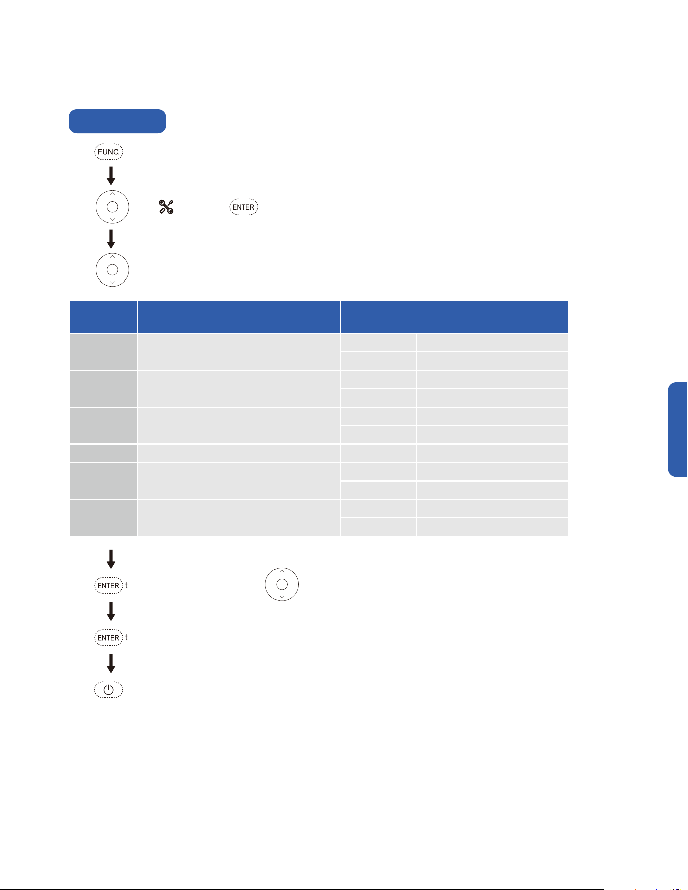
Function
Code
Function Function Parameter
P6 Temperature Unit Setting
°F Degree Fahrenheit
°C Degree Celsius
PA Ambient / Set Temperature
00 Set Temperature
01 Ambient Temperature
PD Thermostat button buzzer
ON Buzzer On
OFF Buzzer Off
A8 Backlight Brightness 30 - 100 Brightness Percentage
B3 Air Filter Reminder
ON Air Filter Reminder On
OFF Air Filter Reminder Off
B4 Clock Display Setting
12 12 Hour Format
24 24 Hour Format
Advance Function
Advance Function
Press .
Press to enter function setting, then press to change the setting.
Press to confirm setting.
Press to exit parameter setting.
Press until blinks, press to enter parameter setting.
Press to choose the parameter / function to set. The display will shows the function code as below:
Parameter Setting
66
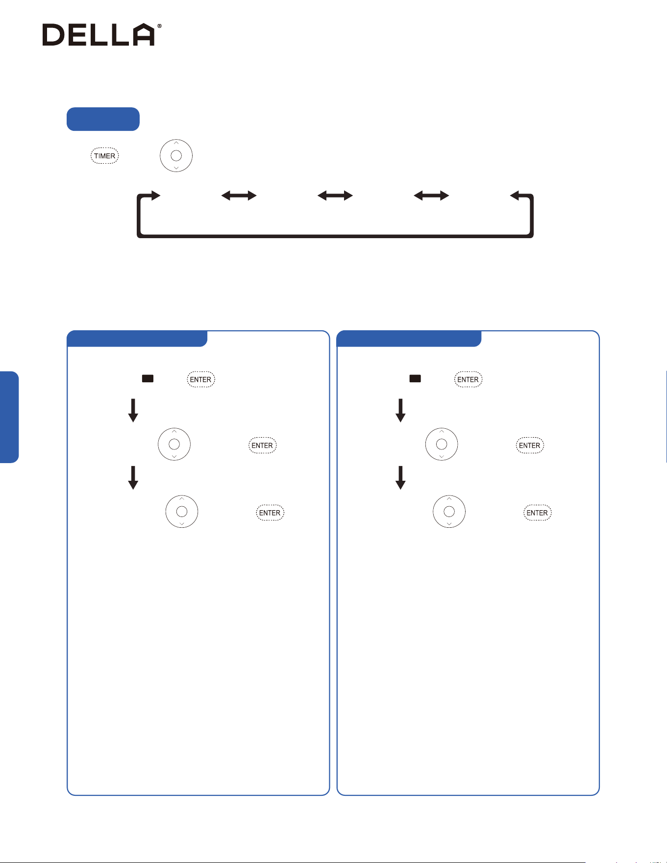
Timer OFF (Shut OFF Timer)
Timer ON (Turn ON Timer)
Advance Function
Advance Function
Timer Setting
Timer
ON
Timer
ON
Timer
OFF
Timer
OFF
Timer
Week 1
Timer
Week 2
Press and then to choose the timer function setting.
Press to confirm. Press to confirm.
Set hour value. Press to adjust, and to confirm. Set hour value. Press to adjust, and to confirm.
Week timer 1 allows you to schedule operation time for a week. The AC will turn-on and off on scheduled time with the same mode and
temperature setting as the last time it was turned off.
Set minute value. Press to adjust, and to confirm. Set minute value. Press to adjust, and to confirm.
ON
OFF
Week timer 2 allows you to schedule operation time for a week. Week timer 2 also support operation mode, temperature setting,and fan speed
customization through out the week.
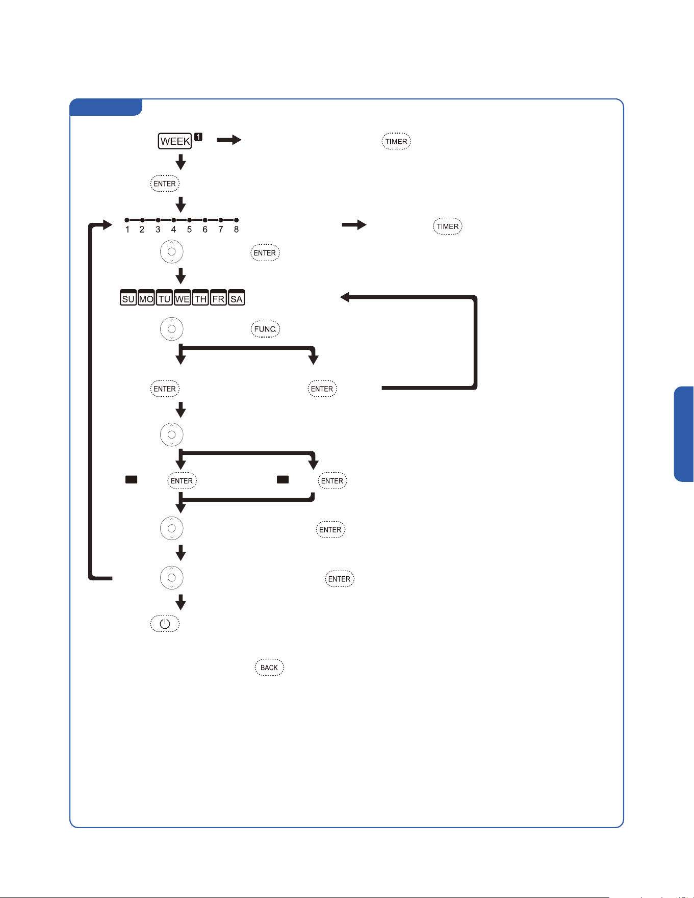
67
v.20251124U
Week Timer 1
Advance Function
Advance Function
When icon flashes, press and hold for 2 seconds to clear all week timer 1 setting
Press and hold for 2 seconds to clear current task
Press to confirm.
Choose target task
Choose day of week
Choose another day
ON (Timer enabled, assign target task) OFF (Timer Disabled)
Press to choose, and to confirm.
Press to confirm.
Press to confirm.
Press to confirm.
Press to confirm.
Press to choose, and on selected day.
Press to choose Turn ON / Shut OFF Timer.
Press to adjust timer hour value, press to confirm.
Press to adjust timer minute value, press to confirm.
Press to confirm and exit timer setting.
ON
OFF
At any step of the setting, press to return to previous step.
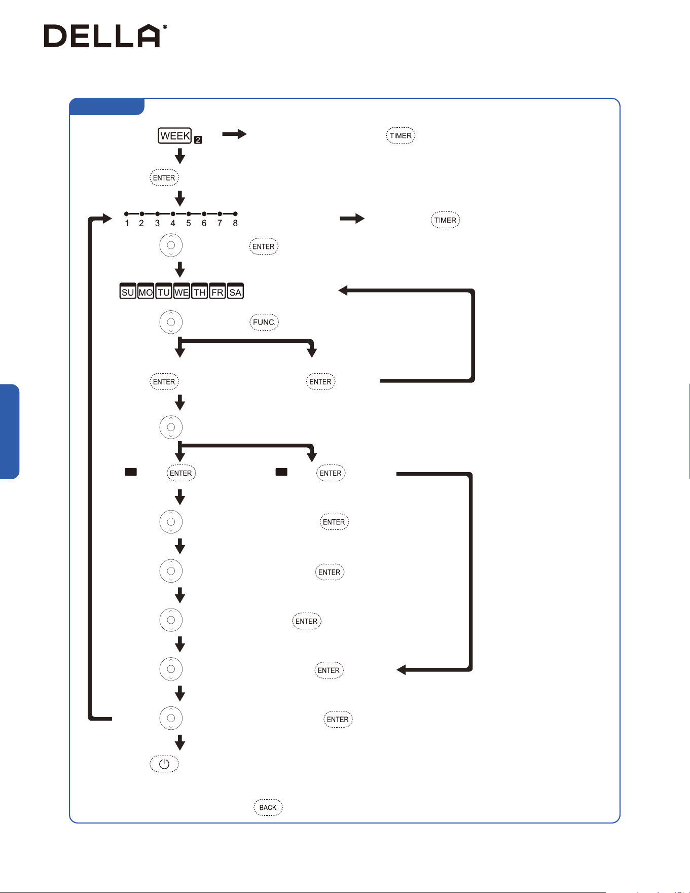
68
Advance Function
Week Timer 2
When icon flashes, press and hold for 2 seconds to clear all week timer 2 setting
Press and hold for 2 seconds to clear current task
Press to confirm.
Choose target task
Choose day of week
Choose another day
ON (Timer enabled, assign target task) OFF (Timer Disabled)
Press to choose, and to confirm.
Press to confirm.
Press to confirm.
Press to confirm.
Press to confirm.
Press to choose, and on selected day.
Press to choose Turn ON / Shut OFF Timer.
Press to choose operation mode, press to confirm.
Press to adjust set temperature, press to confirm.
Press to adjust fan speed, press to confirm.
Press to adjust timer hour value, press to confirm.
Press to adjust timer minute value, press to confirm.
Press to confirm and exit timer setting.
ON
OFF
At any step of the setting, press to return to previous step.
Advance Function
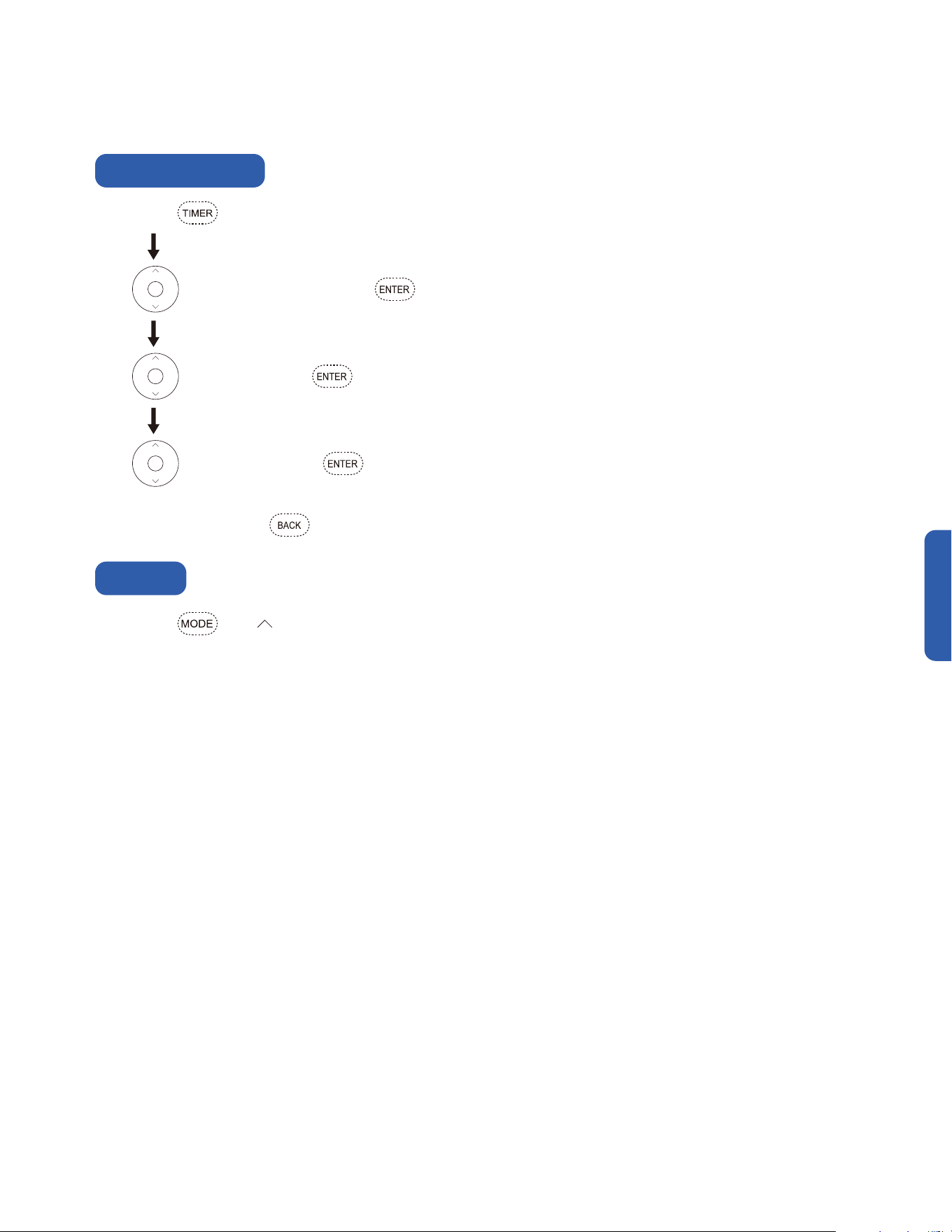
69
v.20251124U
Advance Function
Advance Function
Press and hold for 2 seconds, and the timer display will blink and shows the day of the week.
Press and hold and for 3 seconds to reset wi-fi network for Della App pairing.
Press to select the day of the week, press to confirm.
Press to set hour value, press to confirm.
Press to set minute value, press to confirm.
At any step of the setting, press to go back to the previous parameter setting.
Real-Time Timer Setting
Wi-Fi Reset

70
The Della app combines smart technology with simple, user-friendly
design, providing a seemless experience and endless customization.
Automated smart features work behind the scenes to dialin your
environment and improve your everyday, so you can focus on other, more
interesting things.
remotely,
too.
We work
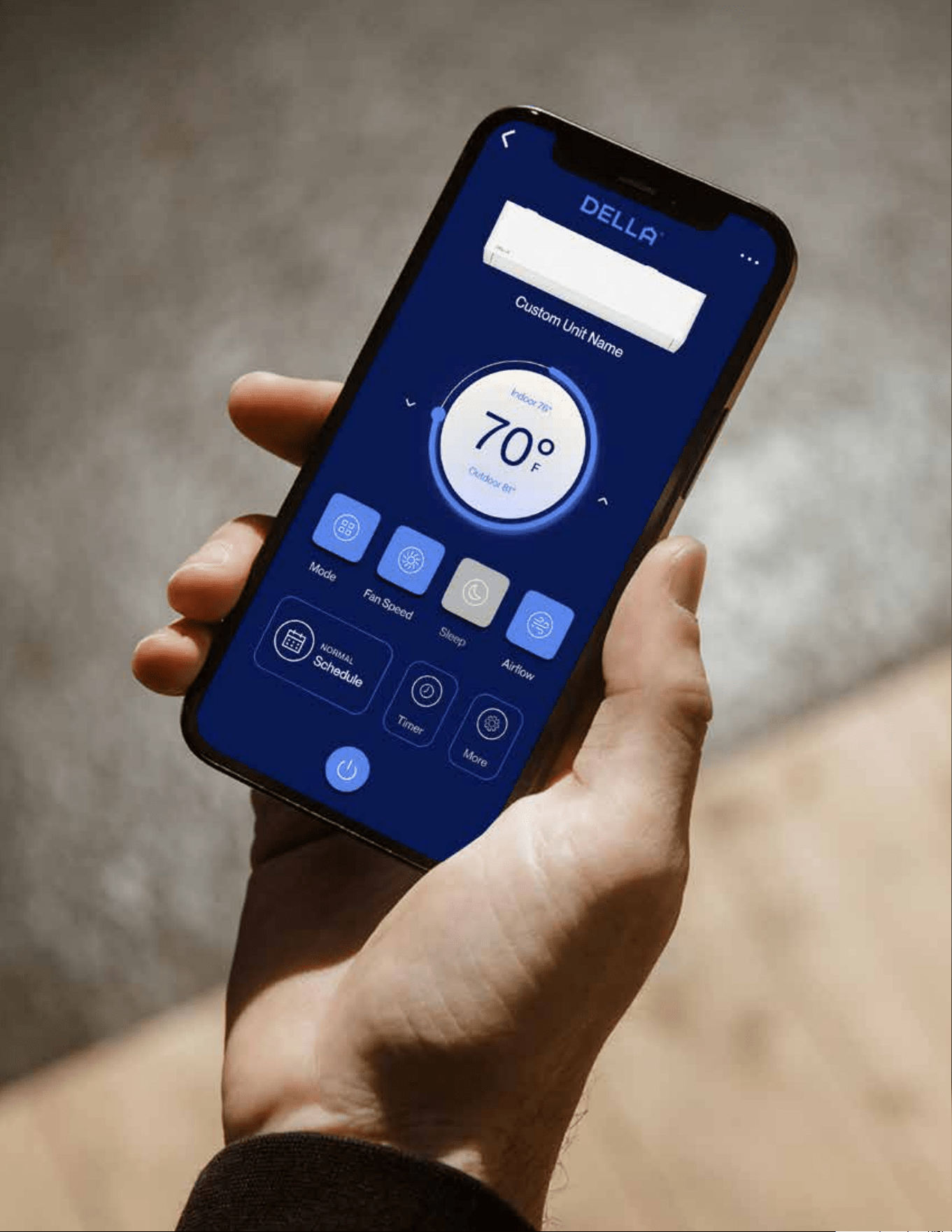
71
v.20251124U
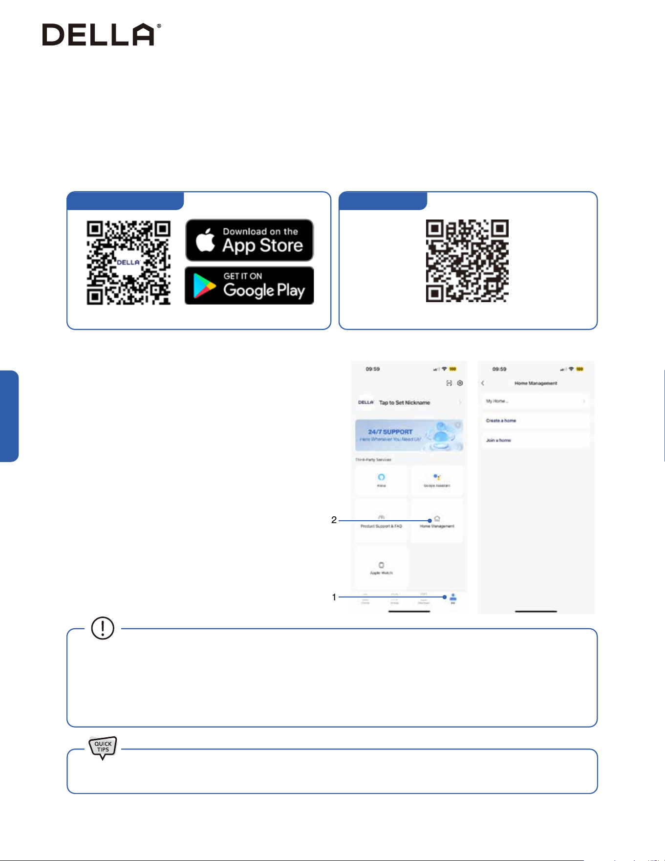
72
Advance Function
DELLA+ App Download
1. Search “DELLA+” on Apple app store or Google Play, or scan the QR code below to download the application.
2. Register an account in the app.
3. Follow the in app instructions to add and pair your Della AC to the app and complete the Wi-Fi set up. You can also scan the device QR code
in the DELLA+ app for a quick device search.
1. Click "Me" on the Della+ app.
2. Choose "Home Management".
3. Follow the in app instructions to create or join a home.
Advance Function
Wi-Fi Set up
Household Set up (Optional)
1
2
To set up the DELLA+ app to control your AC.
Create and Join home to control your Della AC via the Della+ app from
multiple devices and multiple accounts.
NOTE: Pairing your Della AC with a different account outside the
household will remove the original pairing. Only one household can be
paried at a time.
• The Della+ application is free, however, data charges may apply when downloading or using the application.
• Della+ can be altered without notice for quality improvement and also be deleted depending on the circumstances of manufacturing
firms.
• All trademarks, logo, brand names are the property of their respective companies. Use of these names, brands, and trademarks does
not imply endorsement. Della assumes no responsibility with regard to the performance or use of these products.
Check out detailed tutorial on the most updated application on dellahome.com/support.
Scan this QR code in your Della+ app to qucikly add device.You can also scan the download QR code
Device QR code
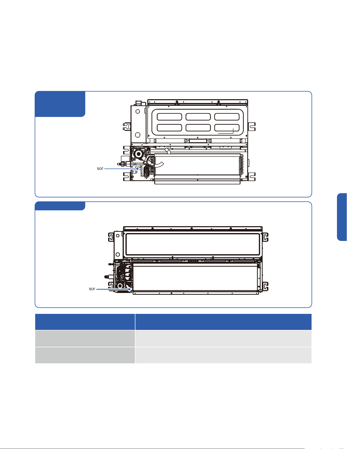
73
v.20251124U
Advance Function
Advance Function
Refrigerant Sensor
• This unit is equipped with a refrigerant leak detector for safety and the unit must be electrically powered at all time after installaion for the
sensor to work effectively and properly other than during servicing.
• The refrigerant sensor automatically detects the condition of the machine while in operation, and it will automatically start air flow circulation
and stop the compressor if refrigerant concentration reaches a pre-set level.
• An error code would displayed in the case of a leak detection.
• The refrigerant sensor has a lifespan of about 15 years and shuld be replaced within the range of its service life.
• The refrigerant sensor must be maintained by a professional and only specified sensor by the manufacturer should be replaced.
Refrigerant Sensor
Refrigerant Sensor
Error Code Description
Hd Refrigerant Leak Protection
Fd Refrigerant sensor communication error
048-DC-9K2V-IN
048-DC-12K2V-IN
048-DC-18K2V-IN
048-DC-24K2V-IN

74
Operation
Operation
Operation Temperature
Preheat
Defrost
Other Operation Requirements
Indoor Temperature Outdoor Temperature
Cool / Dehumidify Mode 63°F - 90°F / 17°C - 32°C 5°F - 131°F / -15°C - 55°C
Heat Mode 32°F - 80°F / 0°C - 27°C -13°F - 86°F / -25°C - 30°C
• The AC performs the best within operational ambient temperature.
• When the ambient temperature is too high, the AC may trip the circuit breaker protection and cause the system to shut down.
• When the ambient temperature is too low, the AC may generate excessive moisture, leading to water dripping from the outdoor unit.
• The indoor unit heat exhanger could preheat for 2 - 5 minutes at the beginning of HEAT mode operation.
• The air conditioner can automatically enters defrost mode when operating in HEAT mode. This procedure may last 2 - 10 minutes.
• During defrosting, the indoor unit fan will stop spinning. Once the defrost cycle ends, the air conditioner will automatically resume HEAT
mode operation.
• When the air temperature is below 5°F / -15°C, the air conditioner needs to be powered on for 2 hours before operation.
• Do not cut off power supply within 1 day of powering off the air conditioner. (It is necessary to have power to the crankcase heater to prevent
the compressor from a force start)
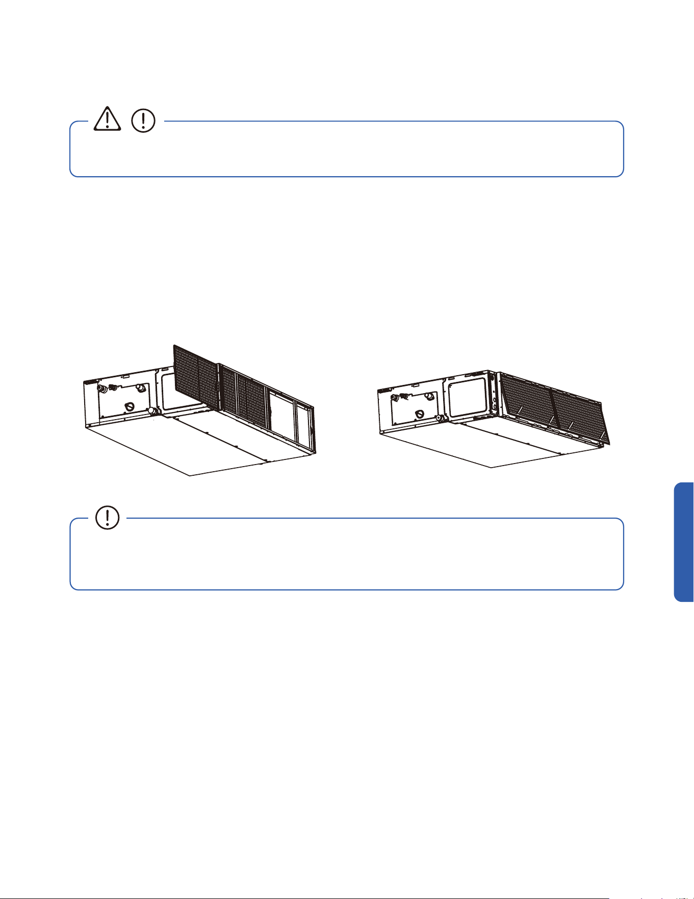
75
v.20251124U
• Before cleaning the unit, you must shut down the machine and cut o the power supply for at least 5 minutes.
• Never ush the air conditioner with water.
• Do not touch the componants inside the indoor unit with bare hands after removing the filter screen.
• Check and clean the air filter regularly to prevent dust accumulation.
• Clean the air filter frequently if the operating environment is dusty or has bad air quality.
1. Remove any possible debris on the air outlet and air return windows to prevent obstruction.
1. Remove the air-return grill from the air conditioner.
2. Clean the air filter with soapy water.
3. Air dry the air filter.
4. Put the air return grill and air filter back to its original position after it is dry.
Care and Maintenance
CAUTION
Clean the Air Outlet and Air Return WIndow
Clean the Air Filter
Care and Maintenance

76
• Clean the air filter screen every 3 months.
• Use the self clean function to clean the indoor unit every 3 months.
-00-
• Call your HVAC technician to check on the refrigerant level every 3 - 4 years.
• Regularly check and remove any obstacles from the outdoor unit.
• Take out the batteries from the remove control and disconnect the power supply of the air conditioner.
• Clean the unit and the air filter screen.
• Remove any obstacles at the air inlet and outlet of both the indoor and outdoor unit.
• Make sure drain pipe is unobstructed.
• Install batteries into the remove control and connect the power supply to the air conditioner.
Planning to Not Operate the Air Conditioner for a Long Period
Using the Air Conditioner After a Long Idle Period
Care and Maintenance
Maintenance Routine
Page 58 / 63
Care and Maintenance
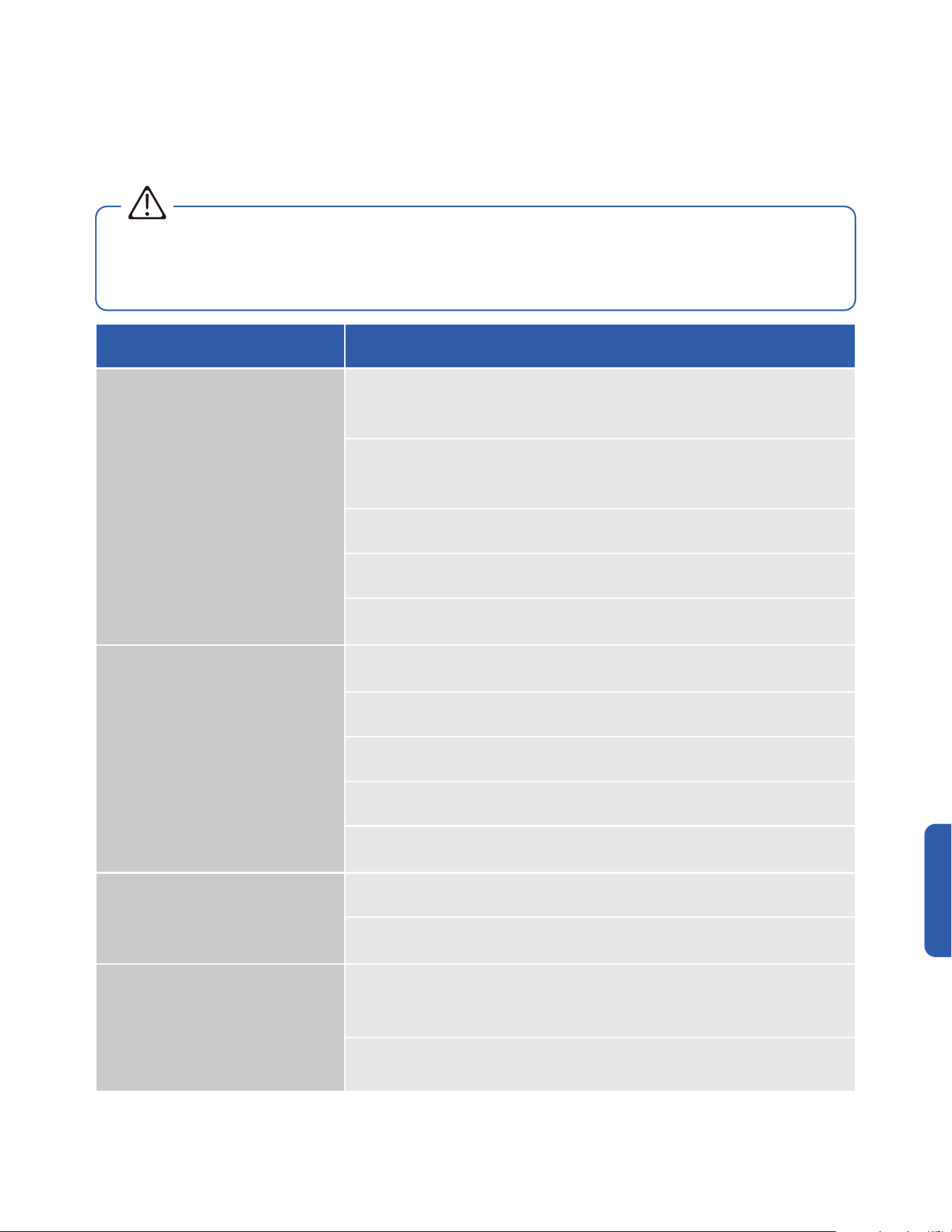
77
v.20251124U
Having Problems?
Before consulting repair or warranty, please check the following troubleshooting guide.
In the case of an persistent problem, contact a qualified technician for diagnosis and repair.
• When encountering persisting problem, stop operation and turn off the breaker. Continue operation in an abnormal condition may
cause electric shock, fire, or damage to the unit.
• Do not attempt to repair or modify the unit by yourself. Incorrect work may result in electric shock, fire or injury.
Problem Possible Cause / Explanation / Solution
The appliance is non operational
When pressing the power button soon after operation was stopped
- Protective delay switch will delay the operation for 3 - 5 minutes if the air conditioner is turned
on immediately after it is turned o.
When switching between operation modes
- The internal protection is activated, wait for a few minutes for the AC to resume normal
operation.
The unit is currently has a turn ON timer activated.
The circuit breaker is tripped. Reset the circuit breaker.
Faulty electric connection, mismatch outlet voltage, or damaged electronic control board.
Contact a qualied technician.
The appliance suddenly stopped during
operation
An internal protection tripped after a sudden voltage uctuation. Check the circuit breaker and
reset if necessary.
The environment temperature is too high or too low.
The AC automatically activate de-frost process. This is not a malfunction.
Air lter is too dirty. Clean the air lter.
Some objects are obstructing air inlet or outlet of the indoor and / or the outdoor unit. Remove
the obstructing object.
Strange odor from the air ow
Air lter is too dirty. Clean the air lter.
The smells of the room, furniture, or cigarettes are absorbed into the unit and then discharged.
Remove odorous objects from the room.
Strange Noise
In the case of water owing noise
- The noise may caused by the refrigerant ow, or the internal water ow during cold / dry
mode. This is not a malfunction.
In the case of plastic cracking noise
- The noise may caused by the thermal expansion.
Troubleshooting
WARNING
78
Problem Possible Cause / Explanation / Solution
Mist comes out from the air outlet
This occurs when the air in the room becomes cold in cool or dry mode. This does not indicate
a problem.
No cool air in cold mode
When switching between operation modes
- The internal protection is activated, wait for a few minutes for the AC to resume normal
operation.
Check and make sure the temperature setting is below the environment temperature.
No warm air in heat mode
When switching between operation modes
- The internal protection is activated, wait for a few minutes for the AC to resume normal
operation.
Check and make sure the temperature setting is below the environment temperature.
The AC automatically activate de-frost process. This is not a malfunction. Wait 2 - 10 minutes for
the AC to complete defrosting.
Frost built up on the outdoor unit. If the AC does not automatically activate de-frost process,
force defrost process following instruction on page 50.
Insucient air ow, either cold or hot
Some objects are obstructing air inlet or outlet of the indoor and / or the outdoor unit. Remove
the obstructing object.
Other heat source of heat in the room. Remove the heat source.
The fan speed is set to minimum. Try to set at a higher fan speed.
The unit does not respond to the remote
control commands
Remote Control is too far away from the indoor unit.
There is an obstruction between the remote control and the indoor unit.
The battery power has run out in the remote control. Replace the battery.
Child lock function is activated. Deactivate child lock on the remote control.
The display on the indoor unit is not lit
The display is set to o on the remote control. Use the remote control to turn it on.
Power failure. Check the power supply / circuit breaker.
Water dripping from the outdoor unit
The indoor unit internal is too dirty and clogged the drainage port. Contact qualied technician
for cleaning.
Condensation formed on the uninsulated drainage hose / refrigerant pipe in the line set.
Contact qualied technician to properly insulate the water hose / refrigerant pipes.
Improper drainage hose installation.
Troubleshooting
Having Problems?
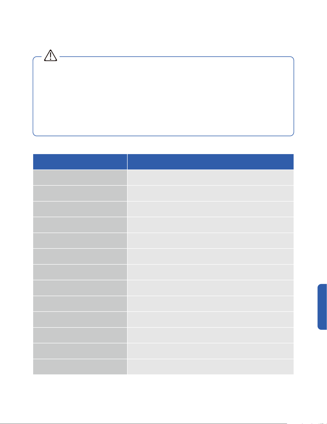
79
v.20251124U
WARNING
Switch off the air conditioner immediately and cut off the power supply in the event of:
• Strange, loud noises during operation.
• Faulty electronic control board.
• Faulty fuses or switches.
• Spraying water or objects inside the appliance.
• Frequent circuit breaker tripped during operation.
• Abnormally hot or damaged power cord or plug.
• Very strong smells discharging from the appliance.
Troubleshooting
Error Code
Having Problems?
Error Code Description
E0 Indoor and outdoor communication failure
E1 Indoor ambient temperature sensor failure
E2 Indoor fancoil temperature sensor failure
E3 Outdoor fancoil temperature sensor failure
E4 Abnormal system malfunction (lack of uroine)
E5 Model conguration error
E6 Indoor PG/DC fan failure
E7 Outdoor ambient temperature sensor failure
E8 Outdoor exhaust temperature sensor failure
E9 Outdoor IPM module failure / Compressor drive failure
EA Outdoor current sensor failure
Eb PCB and display screen communication failure
EC Outdoor modules communication failure
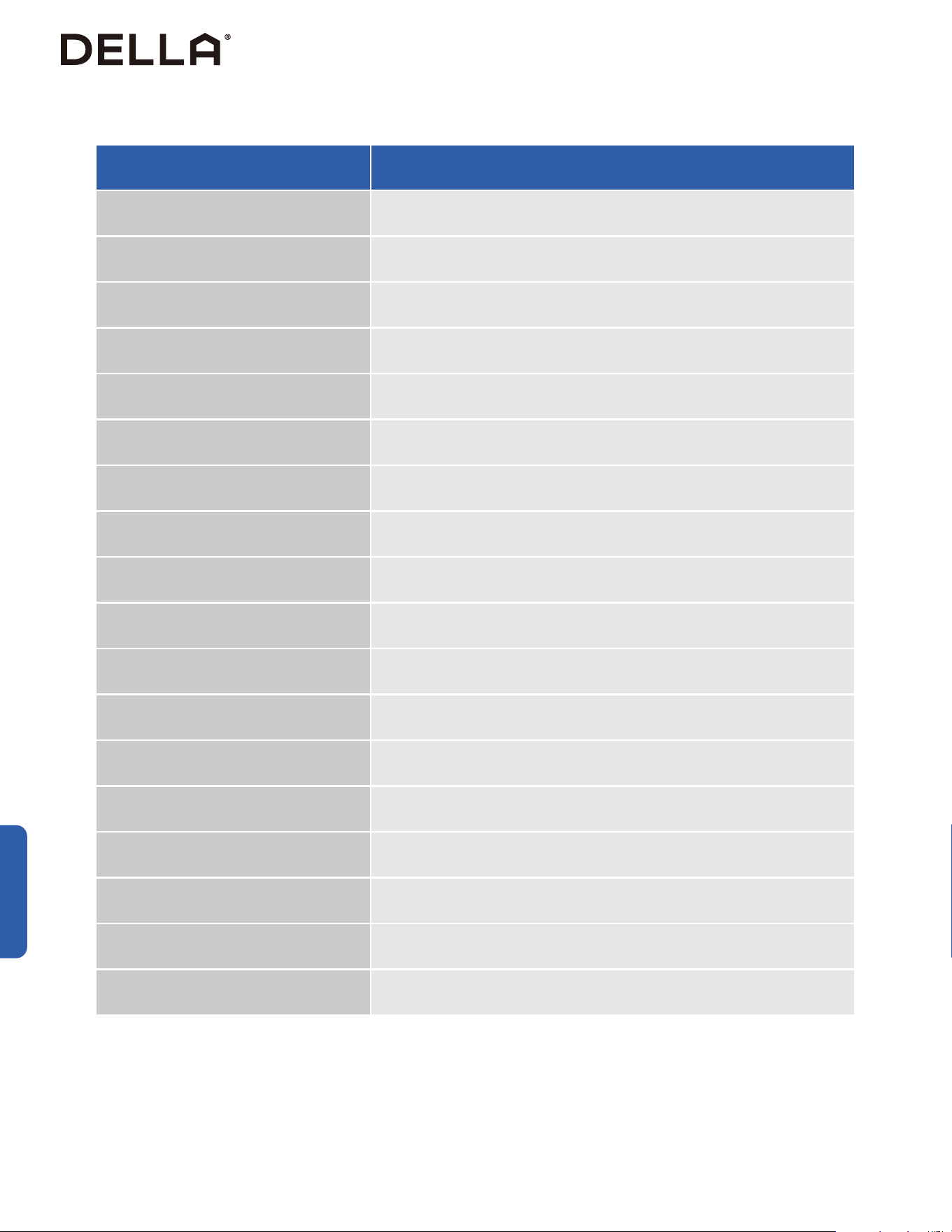
80
Having Problems?
Troubleshooting
Error Code Description
EE Outdoor EEPROM fault
EF Outdoor DC fan failure
EH Outdoor compressor top failure
EU Outdoor voltage sensor failure
Ej Outdoor central coil temperature sensor failure
En Outdoor air pipe temperature sensor failure
Ey Outdoor liquid pipe temperature sensor failure
P0 IPM module protection
P1 Overvoltage and undervoltage protection
P2 Overcurrent protection
P3 Other protections
P4 Protection against excessive outdoor exhaust temperature
P5 Cooling protection against overcooling
P6 Cooling and anti overheating protection
P7 Heating and anti overheating protection
P8 Protection against high or low outdoor temperature
P9 Compressor drive protection (abnormal load)
PA Communication failure / Mode conict

81
v.20251124U
Having Problems?
Troubleshooting
Error Code Description
F0 Infrared human sensing sensor failure
F1 Battery module failure
F2 Exhaust temperature sensor failure protection
F3 Failure protection of outer tuber temperature sensor
F4 Abnormal protection of refrigerant circulation
F5 PFC protection
F6 Compressor missing / Reverse phase protection
F7 Module temperature protection
F8 Abnormal commnication of 4-way valve
F9 Module temperature sensor circuit malfunction
FA Compressor phase current detection fault
Fb Cooling and heating overload protection limit frequency reduction
FC High power protection limit / Frequency reduction
FE Module current (compressor phase current) protection limit / Frequency reduction
FF Drive protection limit / Frequency reduction
FH Drive protection limit / Frequency reduction
FP Anti condensation protection limit / Frequency reduction
FU Anti freezing protection limit / frequency reduction
Fj Exhaust protection limit / Frequency reduction
Fn External AC current protection limit / frequency reduction
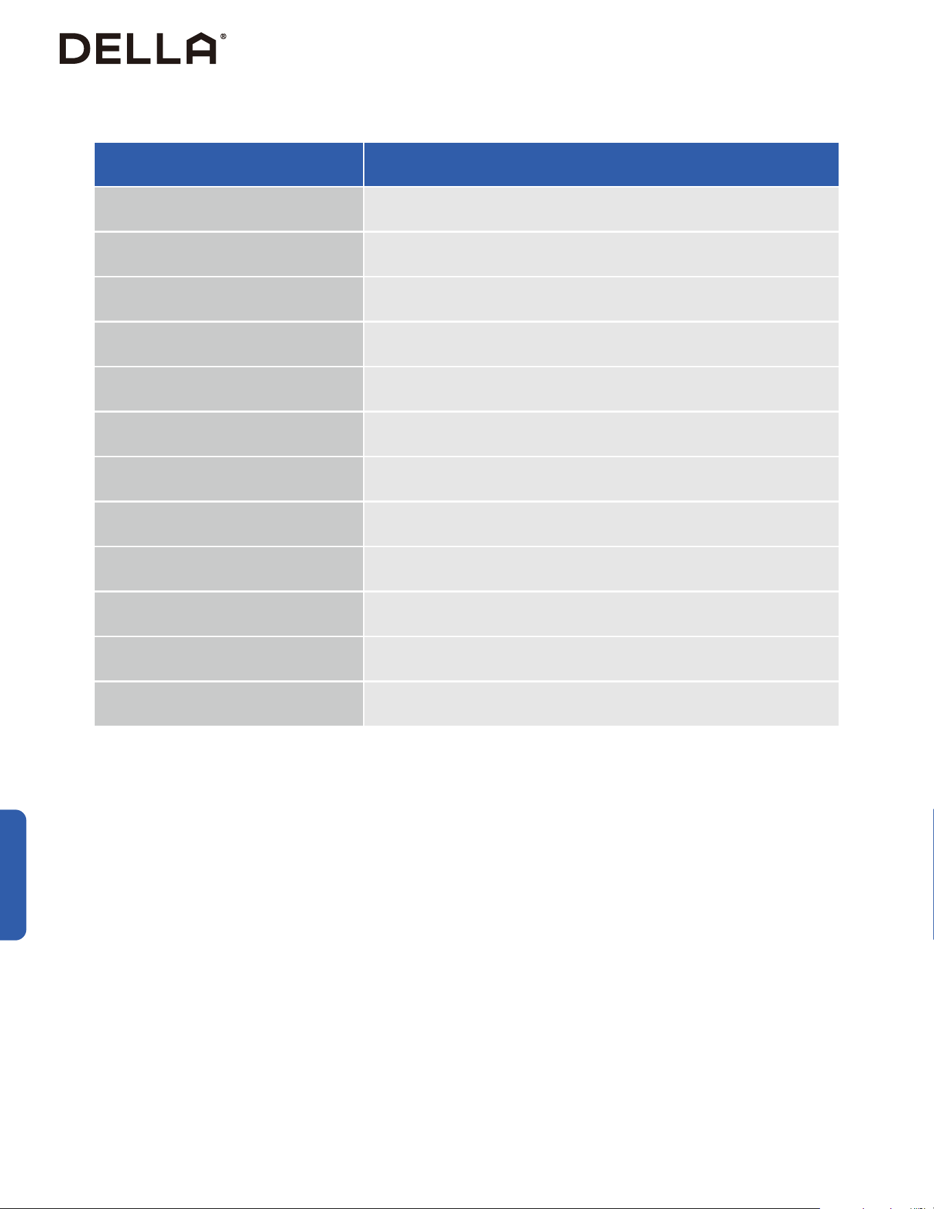
82
Troubleshooting
Having Problems?
Error Code Description
Fy Fluorine deciency protection
H1 High pressure switch malfunction
H2 Low pressure switch malfunction
bf TVOC sensor failure
bc PM2.5 sensor failure
bj Humidity sensor failure
bE CO2 sensor malfunction
bd Fresh air fan failure
d4 Water full protection
d5 Access control protection
Hd Refrigerant Leak Protection
Fd The communication of the refrigerant sensor is abnormal
83
v.20251124U
Having Problems?
Troubleshooting
Error codes shown on the air conditioner display panel only indicates communication problems between parts.
For technicians attempt to identify the exact problematic parts or componants, visit our page on
dellahome.com/optima-tph-r454b-troubleshooting for detailed model specific diagnostic handbook.
dellahome.com/optima-tph-r454b-troubleshooting
Disposal Guideline
This appliance contains refrigerant and other potentially hazardous materials. When disposing of the appliance, follow all federal, state, and local
regulations. DO NOT dispose of this product as normal household waste or unsorted municipal waste.
When disposing of this appliance, you have the following options:
• Dispose of the appliance at a designated municipal electronic waste collection facility.
• When buying a new appliance, the retailer will take the old appliance.
• The manufacturer may take back the old appliance.
• Sell the appliance to a certified scrap metal dealer.

84
Warranty
dellahome.com/pages/warranty
Warranty
Scan the QR code or visit our page on dellahome.com/pages/warranty to sign up for warranty coverage on your new DELLA appliance.

85
v.20251124U
ID: 2ANDL-TCWBRCU1
FCC Caution
This device complies with part 15 of the FCC Rules. Operation is subject to the following two conditions:
(1) This device may not cause harmful interference, and (2) this device must accept any interference received, including interference that may
cause undesired operation. Any changes or modifications not expressly approved by the party responsible for compliance could void the user's
authority to operate the equipment.
NOTE: This equipment has been tested and found to comply with the limits for a Class B digital device, pursuant to Part 15 of the FCC Rules.
These limits are designed to provide reasonable protection against harmful interference in a residential installation. This equipment generates,
uses and can radiate radio frequency energy and if not installed and used in accordance with the instructions, may cause harmful interference
to radio communications. However, there is no guarantee that interference will not occur in a particular installation. If this equipment does cause
harmful interference to radio or television reception, which can be determined by turning the equipment off and on, the user is encouraged to try
to correct the interference by one or more of the following measures:
• Reorient or relocate the receiving antenna.
• Increase the seperation between the equipment and receiver.
• Connect the equipment into an outlet on a circuit different from that to which the receiver is connected.
• Consult the dealer or an experienced radio / TV technician for help.
Radio Frequency Interference
Model: 048-DC series
Compliance Information

86

87
v.20251124U
© Della All rights reserved.
The design and specications are subject to change without prior
notice for product improvement. Any updates to the manual will be
uploaded to the della website.
www.dellahome.com
support@dellahome.com
800–863–4143
6:00 a.m. – 4:00 p.m. PST Monday – Friday