
Installation Manual
TALLAC DISHWASHERS
DWV MODELS
www.zlinekitchen.com

ZLINE Kitchen and Bath provides Attainable Luxury, where the kitchen and bath of your dreams
is never out of reach. Through our unique designs and unparalleled quality, we’re dedicated to
providing you an elevated experience in the heart of your home. With an endless selection of
features and finishes, our inspiration is your reality.

ZLINE is fueled by a passion for innovation; A relentless pursuit of bringing the
highest end luxury designs and professional features into everyone’s homes.
Because we continually strive to improve our products, we may change
specifications and designs without prior notice.
Scan the QR code to view the most up-to-date version of the Installation
Manual and User Manual.
WARNING: This product can expose you to chemicals including Diisononyl phthalate
(DINP) which is known to the State of California to cause cancer.
For more information go to www.P65Warnings.ca.gov.

TABLE OF CONTENTS
IMPORTANT SAFETY INSTRUCTIONS . . . . . . . . . . . . . . . . . . . 1
BEFORE INSTALLATION . . . . . . . . . . . . . . . . . . . . . . . . . . . . . . . 6
Electric Shock Hazard . . . . . . . . . . . . . . . . . . . . . . . . . . . . . . . 6
Tools You May Need . . . . . . . . . . . . . . . . . . . . . . . . . . . . . . . 7
Cutout Dimensions . . . . . . . . . . . . . . . . . . . . . . . . . . . . . . . . 10
INSTALLATION . . . . . . . . . . . . . . . . . . . . . . . . . . . . . . . . . . . . . 11
Adjusting Height . . . . . . . . . . . . . . . . . . . . . . . . . . . . . . . . . 12
Water Supply Connection . . . . . . . . . . . . . . . . . . . . . . . . . . . . 14
Steam Protection Foil . . . . . . . . . . . . . . . . . . . . . . . . . . . . . . 15
Installing the Dishwasher into the Cabinet Cutout . . . . . . . . . . . . . . . 16
Drain Hose Connection . . . . . . . . . . . . . . . . . . . . . . . . . . . . . 17
Adjusting the Kick Plate . . . . . . . . . . . . . . . . . . . . . . . . . . . . . 20
Installer Checklist . . . . . . . . . . . . . . . . . . . . . . . . . . . . . . . . 26
WARRANTY . . . . . . . . . . . . . . . . . . . . . . . . . . . . . . . . . . . . . . . . 27
WARRANTY . . . . . . . . . . . . . . . . . . . . . . . . . . . . . . . . . . . . . . . . 28

1
General Safety
IMPORTANT SAFETY INSTRUCTIONS
WARNING
If the information in this manual is not followed exactly, a fire or explosion
may result causing property damage, personal injury, or death.
When using the dishwasher, carefully follow the precautions in this manual. These are provided
in order to save time and effort and to help ensure optimum dishwasher performance. Be
sure to observe all listed warnings and cautions. Look carefully at WARNING icons with an
exclamation mark inside.
WARNING:
WARNING
Indicates a potentially hazardous situation which, if not avoided, could
result in death or serious injury.
CAUTION:
CAUTION
Indicates a potentially hazardous situation which, if not avoided, may
result in injury. It may also be used to alert against unsafe practices.
NOTICE:
NOTICE
Indicates a potentially hazardous situation which, if not avoided, may
result in damage to the dishwasher, the tableware, the equipment, or the
environment.

2
General Safety
Read these safety instructions completely before installation and operation and follow them
carefully. Save these instructions and pass them on to any future user.
WARNING CAUTION NOTICE
• In addition to these instructions, the dishwasher shall be installed in accordance with all
local codes, or in absence of a local code:
• In the United States, with the National Electric Code ANSI/NPA70-latest edition.
• In Canada, with the Canadian Electric Code C22.1-latest edition/Provincial and
Municipal codes and/or local codes.
When installing the dishwasher, follow basic precautions, including:
• Please check the standards and local codes for dishwasher placement.
• Installation and repair should be performed by a qualified installer, such as an insured
licensed plumber or contractor. Installation performed by non-professionals could be
dangerous and result in improper installation and property damage, which may void
the warranty.
• The information in this user manual must be followed to minimize the risk of fire or
explosion and to prevent property damage, personal injury, or loss of life.
• To reduce the risk of electric shock, fire, or injury, the installer must ensure that the
dishwasher is completely enclosed at the time of installation.
• Never connect the ground wire to gas lines, hot water pipes, or plumbing lines.
• Only connect the dishwasher to the power supply when all installation and plumbing
work is complete.
• Before installation or service, disconnect the power supply to the work area by unplugging
the unit, “tripping” the circuit breaker, or removing the fuse.
• If the dishwasher is installed in a location that experiences freezing temperatures (e.g. in
a vacation home, cabin, etc.), drain all the water from the unit's interior if not using the
unit for extended periods. Water system ruptures that occur as a result of freezing are not
covered by warranty.
• The dishwasher must be secured to adjacent cabinetry using the brackets provided.
Failure to do this may cause damage to property or bodily injury.
• Ensure that any plastic wrappings, bags, small pieces, etc., are disposed of safely and
kept out of the reach of children to prevent risk of suffocation or other serious injury.
IMPORTANT SAFETY INSTRUCTIONS

3
General Safety
• Remove the door to the washing compartment when removing an old dishwasher from
service or discarding it. Ensure that the appliance presents no danger to children while
being stored for disposal.
• The dishwasher drain hose must be installed with a drain loop at least 30" (762 mm) off
the cabinet floor or an appropriate air gap device. Otherwise, the dishwasher may not
drain properly.
• This dishwasher is intended for residential use only and should not be used in commercial
establishments. This appliance is not applicable for outdoor usage. The manufacturer
disclaims responsibility for damage or injury caused by improper use of this appliance.
• Do not operate the appliance if it's damaged, malfunctioning, partially disassembled,
or has missing or broken parts. If the unit arrives damage, contact ZLINE at
1-614-777-5004 for help.
• If the dishwasher is a new installation, please note that most of the work must be done
before the dishwasher is moved into place.
• If the dishwasher is replacing another dishwasher, check the existing dishwasher
connections for compatibility with the new dishwasher and replace parts as necessary.
• Use only detergents or wetting agents recommended for use in a dishwasher and keep
them out of the reach of children.
• The manufacturer reserves the right to make changes to its products when considered
necessary and useful, without affecting the essential safety and operating characteristics.
• Refer to the Installation Manual provided with your dishwasher for additional installation
details and safety measures.
• The serial number information is located on the right-hand side of the inner door of
the dishwasher.
Example serial number label:
IMPORTANT SAFETY INSTRUCTIONS

4
General Safety
IMPORTANT SAFETY INSTRUCTIONS
• When loading items into the dishwasher:
• Locate sharp items so that they are not likely to damage the door seal.
• Load sharp knives with the handles up to reduce the risk of cut-type injuries.
• Do not wash plastic items unless they are marked “dishwasher safe” or the equivalent.
For plastic items not marked, check the manufacturer’s recommendations.
• Do not touch the heating element during or immediately after use.
• Do not operate the dishwasher unless all enclosure panels are properly in place.
• Do not tamper with controls.
• Do not abuse, sit on, or stand on the door or dish rack of the dishwasher.
• The cup racks are designed to support cups, glasses, and kitchen utensils. When the
cup racks are in the dishwasher, do not lean on or use the cup racks to support your
body weight.
• Some dishwasher detergents are strongly alkaline. They can be extremely dangerous
if swallowed. Avoid contact with the skin and eyes and keep children away from the
dishwasher when the door is open.
• Consult Poison Control or a doctor if detergent has been swallowed or inhaled.
• Do not remove dishes from the appliance until the program is complete. Some detergent
may remain on the dishes.
• Check that the detergent dispenser is empty after the completion of each wash program.
• Do not drink and play with the water in the appliance. Harmful residues could be present.
• To reduce the risk of injury, do not allow children to play in or on the dishwasher.
• Do not leave the appliance with the open door unattended to avoid stepping
accidentally onto it.
• Do not use high pressure water sprays and/or steam to clean the appliance.
• Ensure that there are no visible water leaks during and after the first use of the appliance.
• To avoid floor damage and possible mold growth, do not allow wet areas to remain
around or under the dishwasher.

5
Recycling
IMPORTANT SAFETY INSTRUCTIONS
CAUTION
To avoid risk of injury, always use caution when opening the door during or
following a wash cycle, as hot water or steam may escape.
• Do not store or use flammable liquids or vapors in the immediate surrounding area of the
dishwasher or on the appliance.
• Under certain conditions, hydrogen gas may be produced in a hot-water system that has
not been used for two weeks or more. HYDROGEN GAS IS EXPLOSIVE. If the hot-water
system has not been used for such a period, before using the dishwasher, turn on all
hot-water faucets and let the water flow from each for several minutes. This will release
any accumulated hydrogen gas. As the gas is flammable, do not smoke or use an open
flame during this time.
• Please check the water supply line periodically. It is susceptible to breakage. It becomes
less flexible as time goes by. Replace it immediately when it is torn, cut, swollen, or if
there is water leakage.
• Please keep the dishwasher packaging out of the reach of children after unpacking it.
RECYCLING
• Old appliances may contain materials that can be recycled. Please contact the local
recycling authority about the possibility of recycling these materials.
• Remove the door to the washing compartment when removing an old dishwasher from
service or discarding it. Ensure that the appliance presents no danger to children while
being stored for disposal. Before disposing the dishwasher:
• Disconnect the appliance from the main supply.
• Cut off the main cable and discard it.
• Remove the door catch to prevent children and pets from getting trapped in
the appliance.

6
Electric Shock Hazard
BEFORE INSTALLATION
WARNING
ELECTRIC SHOCK HAZARD
• Connect the dishwasher to a properly rated, protected, and sized power supply circuit
to avoid electrical overload.
• The dishwasher is designed for a 120 VAC/60Hz electrical supply connected to a
dishwasher-de dicated, properly grounded, electrical circuit with a fuse or breakers
rated for 15 amperes.
• Do not use any extension cord or portable outlet device to connect the dishwasher to a
power supply. Using an extension cord may void the warranty.
• This appliance must be electrically grounded. In the event of a malfunction or breakdown,
grounding will reduce the risk of electric shock by providing a path of least resistance for
electric current.
• This appliance is equipped with a cord having an equipment-grounding conductor and
a grounding plug. The plug must be plugged into an appropriate outlet that is installed
and grounded in accordance with all local codes and ordinances.
• The manufacturer will not be responsible for any damage to property or to persons
caused by incorrect installation, improper use of the appliance, or failure to heed the
warnings listed.
• IMPORTANT: The installer should leave these instructions with the consumer who should
retain for local inspectors’ use and for future reference.
WARNING
Improper connection of the equipment-grounding conductor can result in
electric shock. Check with a qualified electrician or service representative if
there is doubt whether the appliance is properly grounded. Do not modify the
plug provided with the appliance. If it will not fit the outlet, have a proper outlet
installed by a qualified electrician.
7
Tools and Materials
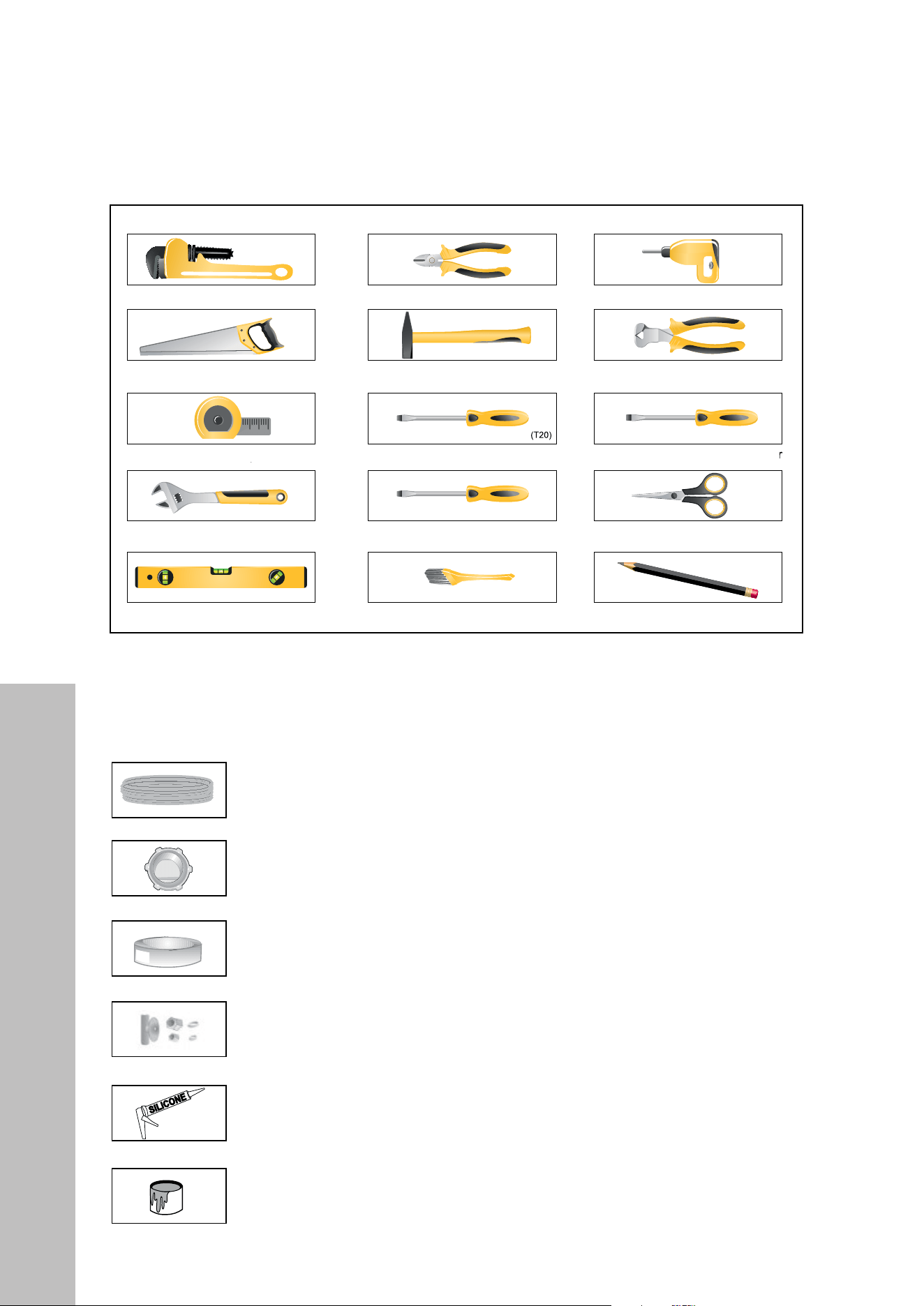
TOOLS YOU MAY NEED
Pipe Wrench Wire Cutter Drill
Hole Saw Hammer Wire Stripper
Tape Measure Torx Screwdriver Phillips Screwdriver
Adjustable Wrench
Flathead Screwdriver Scissors
Level Brush Pencil
MATERIALS YOU MAY NEED:
(Please note additional materials may be required to comply with local codes)
Hot Water Supply Line: Minimum 3/4" O.D. copper tubing or metal-
braided dishwasher supply line
UL listed conduit connector or strain relief
Teflon tape or other pipe thread compound to seal plumbing connections
Shut-off valve and fittings appropriate for hot water supply line (copper
tubing/compression fitting or braided hose)
Silicone
Glue
BEFORE INSTALLATION
8
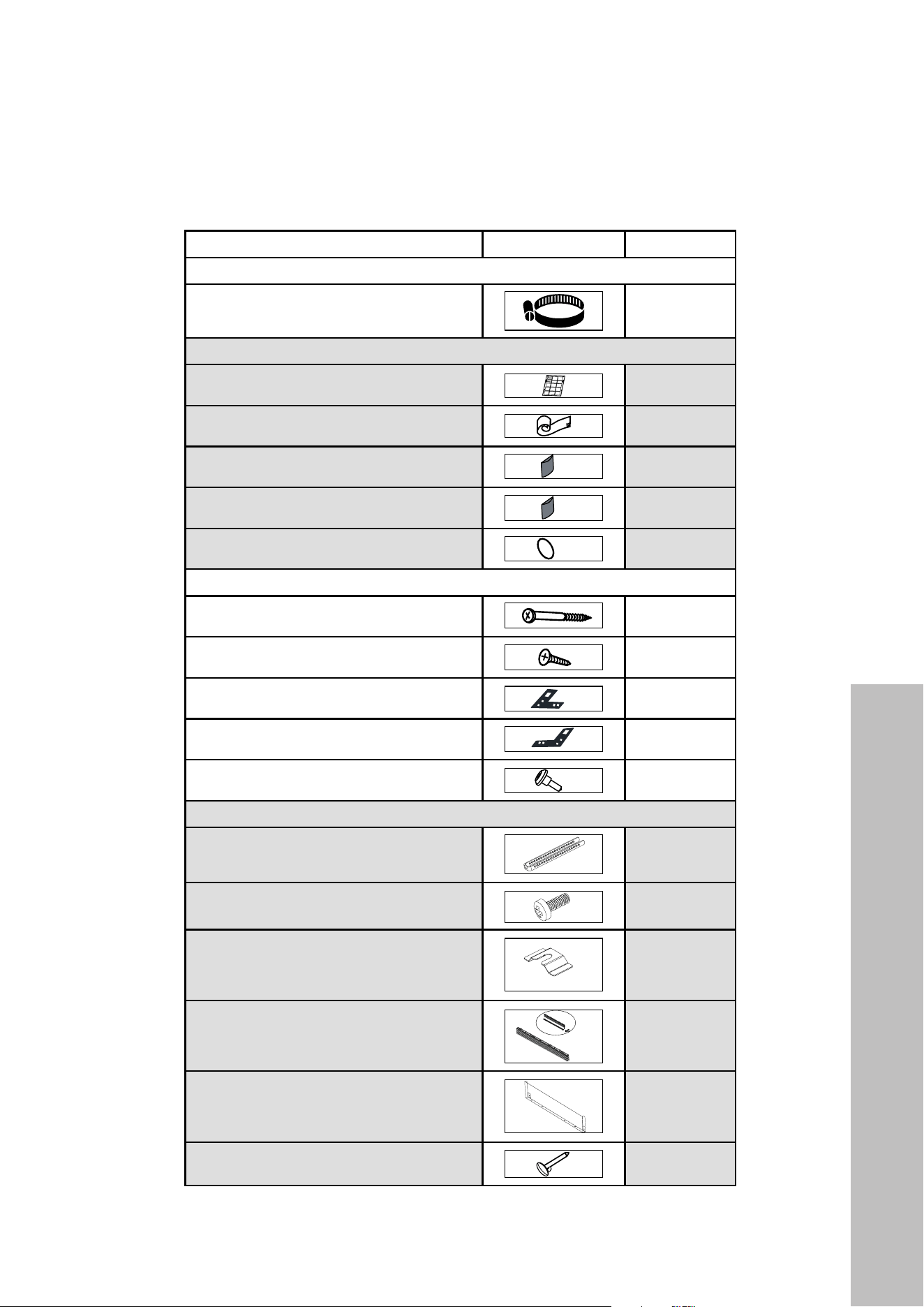
Included Parts
The parts required for installing the dishwasher are enclosed in plastic bags within this
product's packaging. Check that all of the following parts are included.
NAME IMAGE QUANTITY
DISHWASHER PARTS BAG 1
a. Hose Clamp
1
DISHWASHER PARTS BAG 2
b. Installation Manual
1
c. Steam Protection Foil
2
d. Adhesive Panel Strip (Left)
1
e. Adhesive Panel Strip (Right)
1
f. Hole Covers
4
DISHWASHER PARTS BAG 3
g. Screws 5/32" x 1 5/8"
6
h. Screws 5/32" x 19/32"
2
i. Mounting Bracket Left
1
j. Mounting Bracket Right
1
k. Mount Screws 5/32" x 27/32"
2
DISHWASHER PARTS BAG 4
l. Kick Plate Bracket
2
m. Screws 5/32" x 7/32"
2
n. U-Clip
4
o. Adjustable Plinth Cover
1
p. Metal Back Plate
1
q. Stopper Pin
2
BEFORE INSTALLATION
9
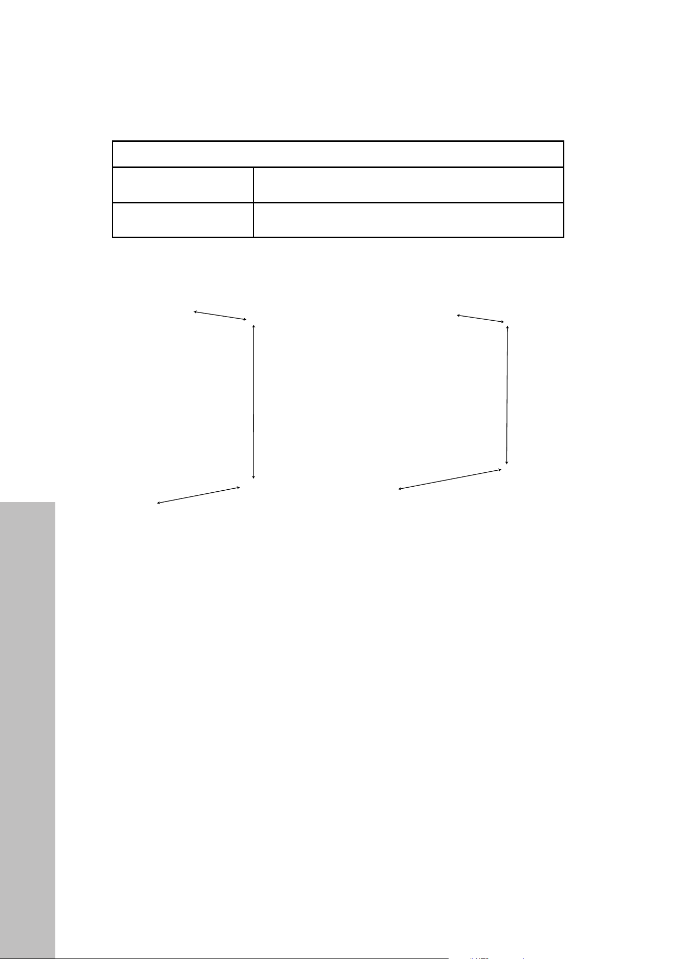
Product Dimensions
PRODUCT DIMENSIONS
SPECIFICATIONS
DWV-18 Dimensions
(18" Model - Panel Ready)
•17 5/8" W x 21 3/4" D x 32 1/8" (min) - 34 1/8" (max) H
•448 mm W x 552 mm D x 816 mm (min) - 867 mm (max) H
DWV-24 Dimensions
(24" Model - Panel Ready)
•23 1/2" W x 21 3/4" D x 33 3/4" (min) - 35 3/4" (max) H
•597 mm W x 552 mm D x 857 mm (min) - 908 mm (max) H
DWV-18 DWV-24
32 1/8" - 34 1/8"
(816 mm - 867 mm)
21 3/4" (552 mm)
17 5/8" (448 mm)
33 3/4" - 35 3/4"
(857 mm - 908 mm)
21 3/4" (552 mm)
23 1/2" (597 mm)
PRE-INSTALLATION NOTES:
• When installing a ZLINE door panel (see instructions on page 22), the depth of each
unit increases to 22 1/2" (572 mm). The depth of each unit including the panel and
handle is roughly 24" (610 mm). Depths may vary if you install a custom panel.
• Minimum and maximum heights take into account the legs, which can be extended on
both models by roughly 2" (51 mm).
• Minimum recommended cabinet cut-out dimensions based on the panel ready
specifications are outlined on page 10.
• While the depth cutout is based on standard cabinet depths of 24" (610 mm), please
note the depth of the unit itself is smaller.
• In order for the door panel of the dishwasher to be flush with the leading edge of the
counter top, the counter top must be at least 22 1/2" (572 mm) deep. This depth may
vary if you install a custom door panel.
BEFORE INSTALLATION
10
CUTOUT DIMENSIONS
Width:
17 3/4"
(451 mm)
Depth:
24" (610 mm)
Height:
32 1/2"34 1/2"
(826 mm867 mm)
DWV-18
DWV-24
Width:
23 5/8"
(600 mm)
Depth:
24" (610 mm)
Height:
34"36"
(864 mm914 mm)
NOTE: Since kitchen layouts vary, ZLINE recommends consulting with a professional
installer to verify cabinet dimensions before installing the appliance.
BEFORE INSTALLATION
Cutout Dimensions
11
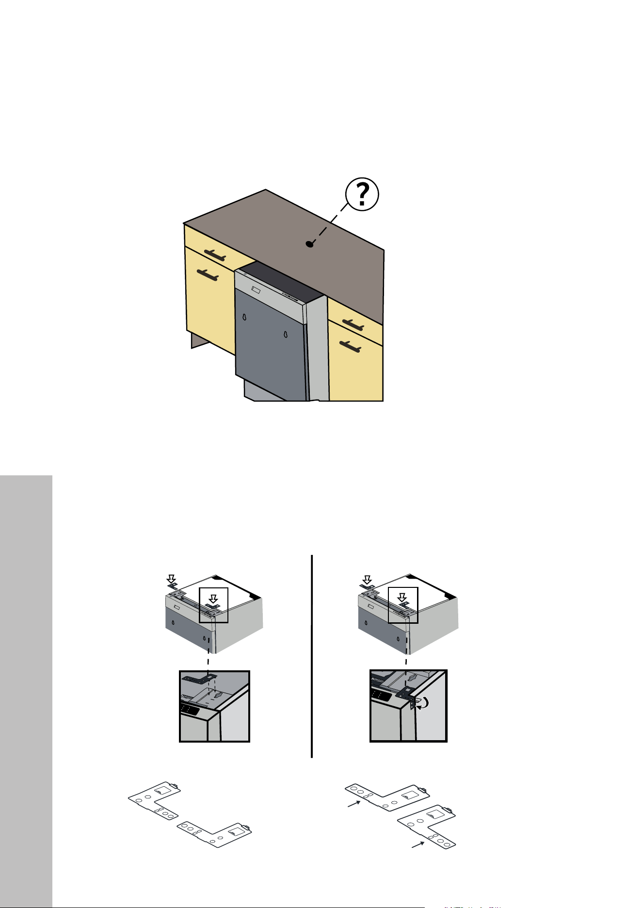
The mounting brackets in Parts Bag 3 must be used when installing the dishwasher in the
cabinetry. Use of any parts other than mounting brackets may result in damage to property
or bodily injury.
Bend brackets
at arrows
to mount to
side of cabinets
Place the two mounting
brackets into the top corner
of the dishwasher like so.
If the material (granite, slate, stone, etc.)
of the countertop cannot be easily drilled
or screwed into, align the brackets in this
manner (below right).
If the material (wood) under the
countertop can be drilled or
screwed into, align the brackets
in this manner (below left).
INSTALLATION
Mounting Brackets
12
Adjusting Height
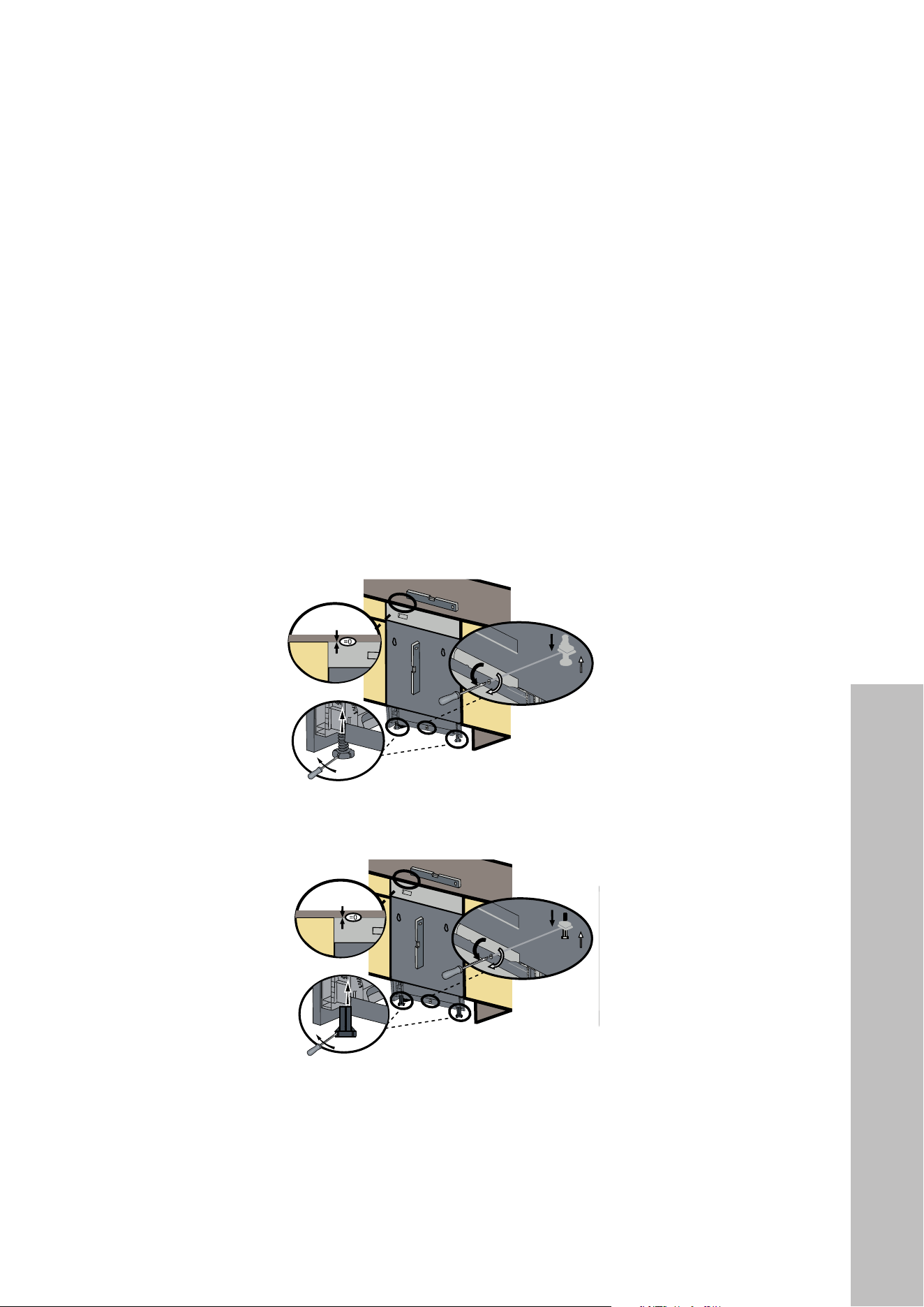
ADJUSTING HEIGHT
1. Before the dishwasher is placed into the cabinetry, the two front legs will be completely
retracted. Adjust the legs by turning in the direction of the black arrows (noted below) with a
flathead screwdriver to allow for the unit to move downwards.
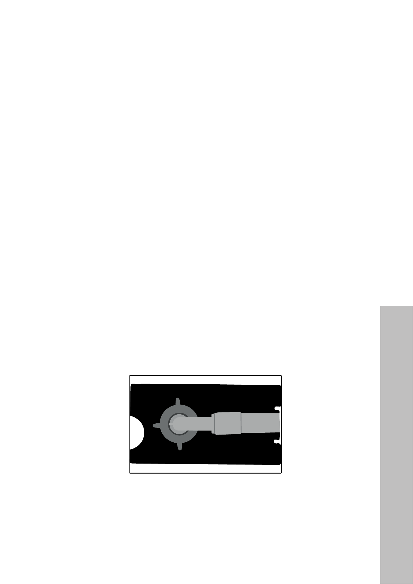
2. For the back leg, using a Phillips screwdriver, turn the height adjustment screw in the middle of
the lower front panel as shown in the image. Turning counter-clockwise (in the direction of the
black arrow) will lower the rear dishwasher leg, and turning clockwise will raise the rear leg.
3. Once the front two legs and rear leg are lowered, move the dishwasher into the cabinetry
and adjust the legs as necessary to balance and raise the dishwasher to the enclosure height.
4. Make sure the dishwasher is plumb with the countertop above.
• NOTE: When engaging the rear leg adjustment screw, if it doesn't move, hold and pull the
leg with your free hand (or use a helper) to loosen the leg before installing.
DWV-18 MODEL
If height of the enclosure is 32 1/8" (816 mm) to 34 1/8" (867 mm), use the short leg supports
as shown in the figure above.
If the height is above 34 1/8" (867 mm), use the long leg supports as shown in the figure above.
INSTALLATION
13
INSTALLATION
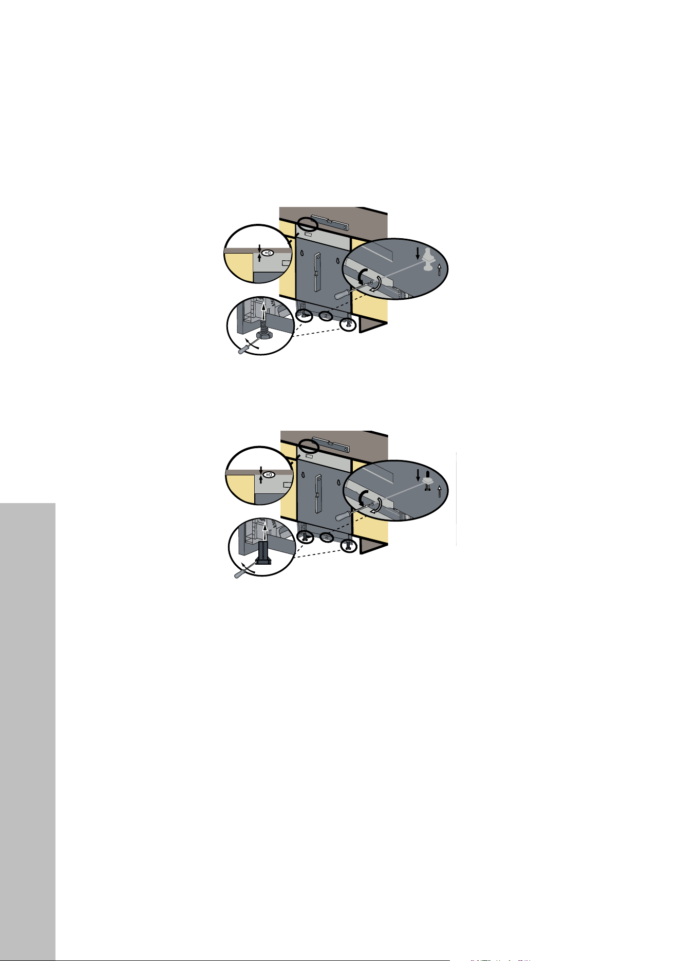
DWV-24 MODEL
If the height of the enclosure is 34" (864 mm) to 36" (914 mm), use the short leg supports as
shown in the figure below.
If the height of the enclosure is above 36" (914 mm), use the long leg supports as shown in
the figure below.
Using a level, be sure to check the dishwasher is level front to back and square to the floor
and countertop.
NOTE: The dishwasher legs can be adjusted up to 2" (51 mm) taller or shorter depending on
the height of your cabinet cutout. Adjust accordingly to ensure the unit is plumb.
Adjusting Height
14
Water Supply Connection
INSTALLATION
WATER SUPPLY CONNECTION
The water supply may be connected to the dishwasher in one of two ways:
• With a metal-braided hose.
• With copper tubing.
Braided Hose/Copper Tubing:
• After connections are made, turn on the water supply to check for leaks.
• Hot water supply line: Use minimum 3/4" O.D. copper tubing or metal-braided
dishwasher supply line.
• Water Inlet valve of the dishwasher has a 3/4"-11.5NH inlet coupling thread dimension
according to ASME B1.20.7-1991.
• When buying a water inlet hose for the dishwasher, please choose the thread dimension
of the inlet hose that is compatible with the indicated water inlet valve inlet coupling
thread dimensi on (3/4"-11.5NH) of the dishwasher.
• Temperatures required for soldering and sweating will damage the dishwasher’s water
inlet valve, so if any such operation is needed, keep the heat source a minimum of
7"–8" (178 mm–203 mm) away from the dishwasher’s water inlet valve.
• There should not be any sharp bends in the water line, as this may restrict the water flow.
• Teflon tape or pipe thread compound must be used for sealing the connection. Before
connecting the copper water supply line to the dishwasher, flush it with hot water to
clear any foreign material.
15
STEAM PROTECTION FOIL
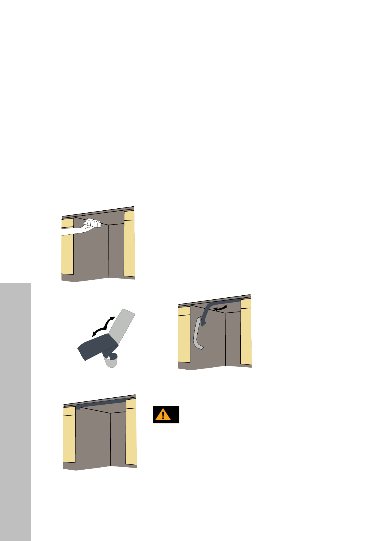
Steam will escape when the dishwasher door is opened during operation of the dishwasher
and after completion of any of the unit's working cycles. In order to prevent the resulting
steam from collecting and damaging at the underside of the countertop, we recommend
using the steam protection foil provided with this unit.
Fitting the Protection Foil
Clean the surface with a damp cloth. To install the steam protection foil (letter "c" from the
parts list on page 8), peel off the protective layer and carefully apply the strip to the
bottom of the cabinet above.
Steam protection foil must be applied where
the steam escapes when door is first opened.
Failure to install the steam protection foil
during installation can lead to damage to the
cabinets and countertop.
CAUTION
INSTALLATION
Steam Protection Foil
16
Dishwasher Placement
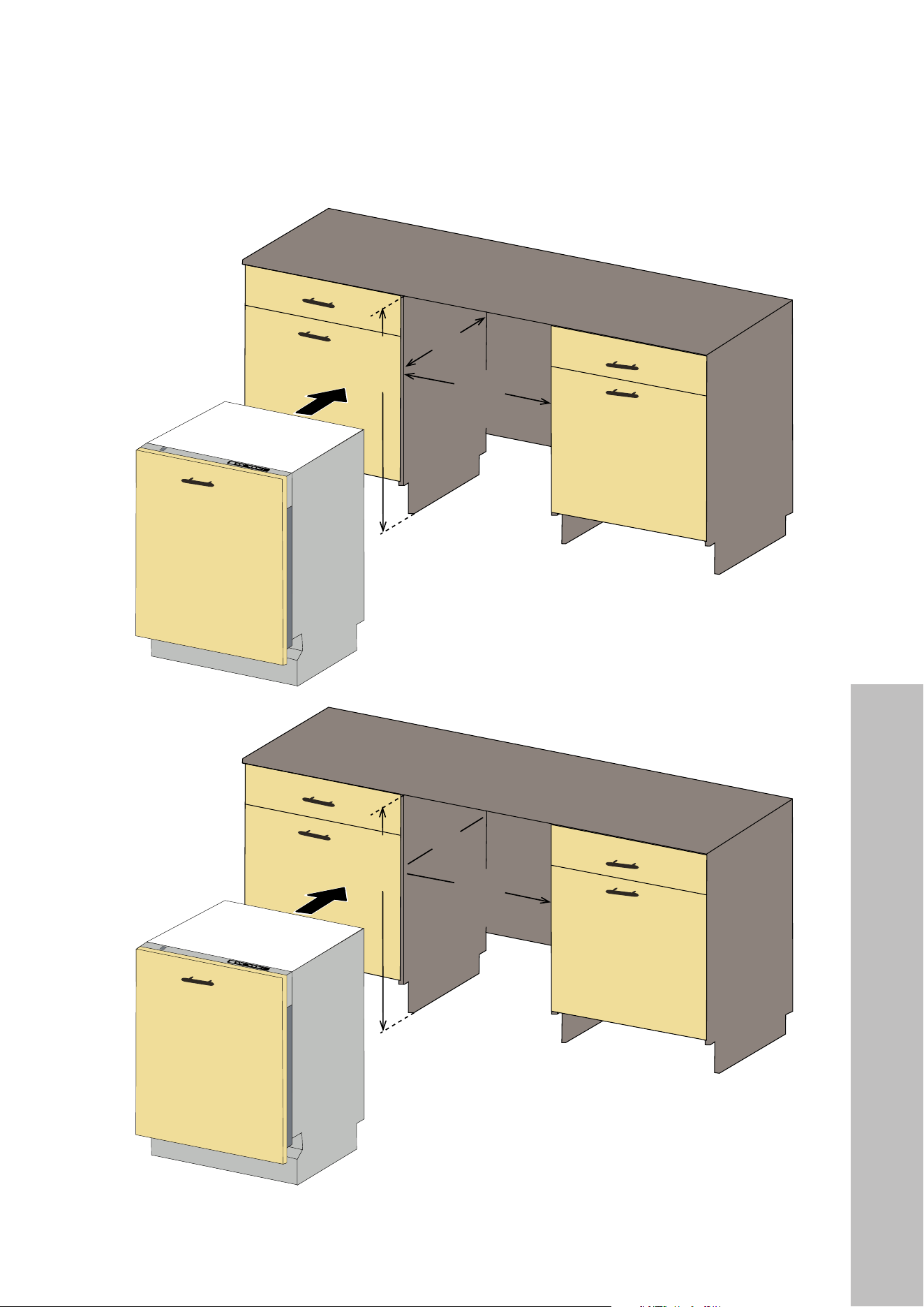
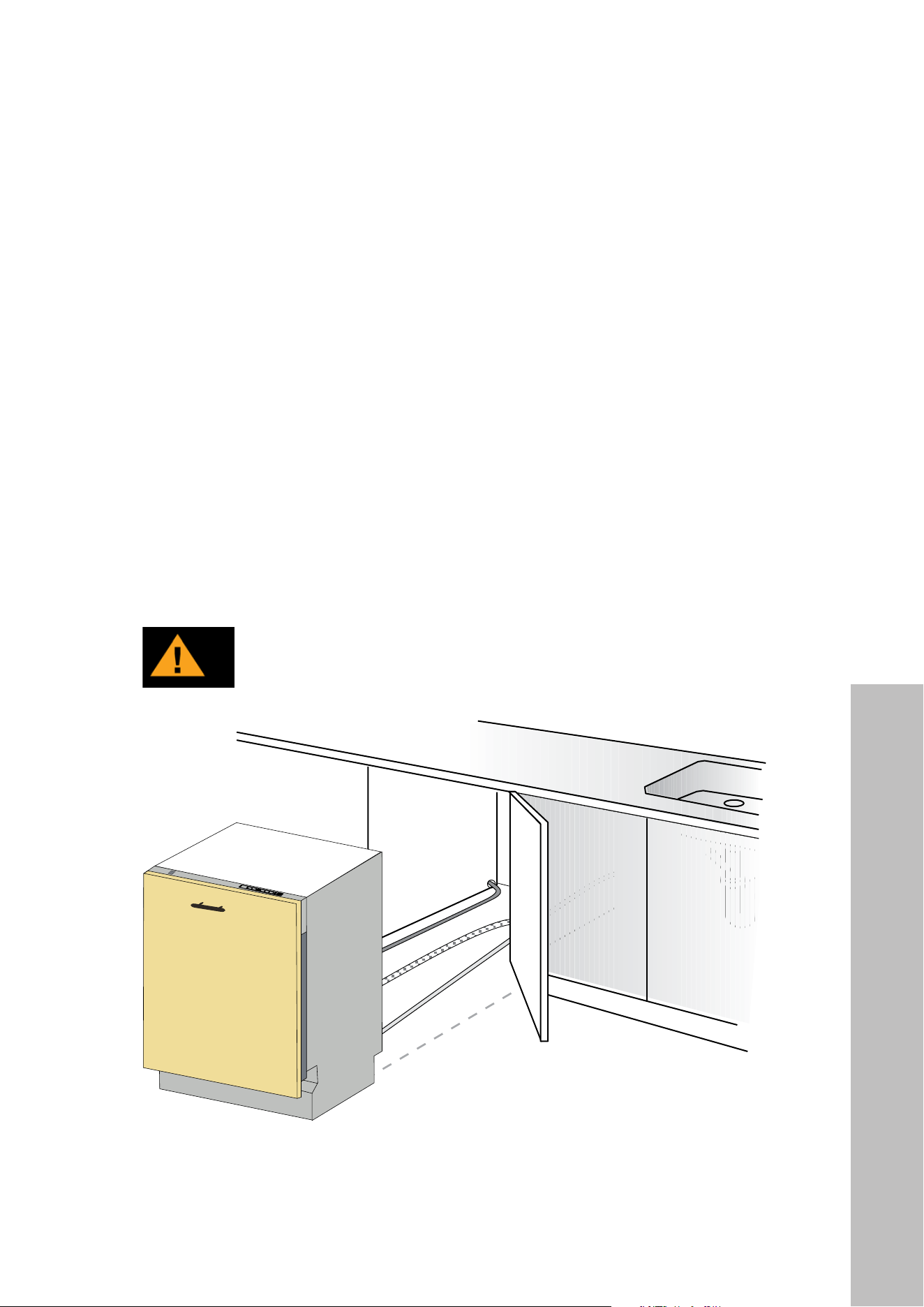
INSTALLING THE DISHWASHER INTO THE CABINET CUTOUT
Place the dishwasher in front of the cabinet opening and get ready to connect all hoses and
electrical connections.
• The electrical-supply receptacle for the appliance must be installed in a cabinet or on a
wall adjacent to the undercounter space where the appliance will be installed.
• There should be an opening through the partition between the compartments specified
in the above bullet point that is large enough for the electrical plug to pass through. The
longest dimension of the opening shall not be more than 1 1/2" (38 mm).
• The edges of the panel opening specified in the above bullet point if made of wood
should be made smooth and rounded. If the panel is made of metal, it should be covered
with a suitable edge protector or grommet (not provided) made for this purpose by the
manufacturer.
• Care shall be exercised when the appliance is installed or removed to reduce the
likelihood of damage to the power-supply cord and reduce risk of injury.
CAUTION
Make sure all hoses are pulled through the side opening of the cabinet,
no hoses are kinked, and all slack is taken out as shown in the figure.
INSTALLATION
17
INSTALLATION
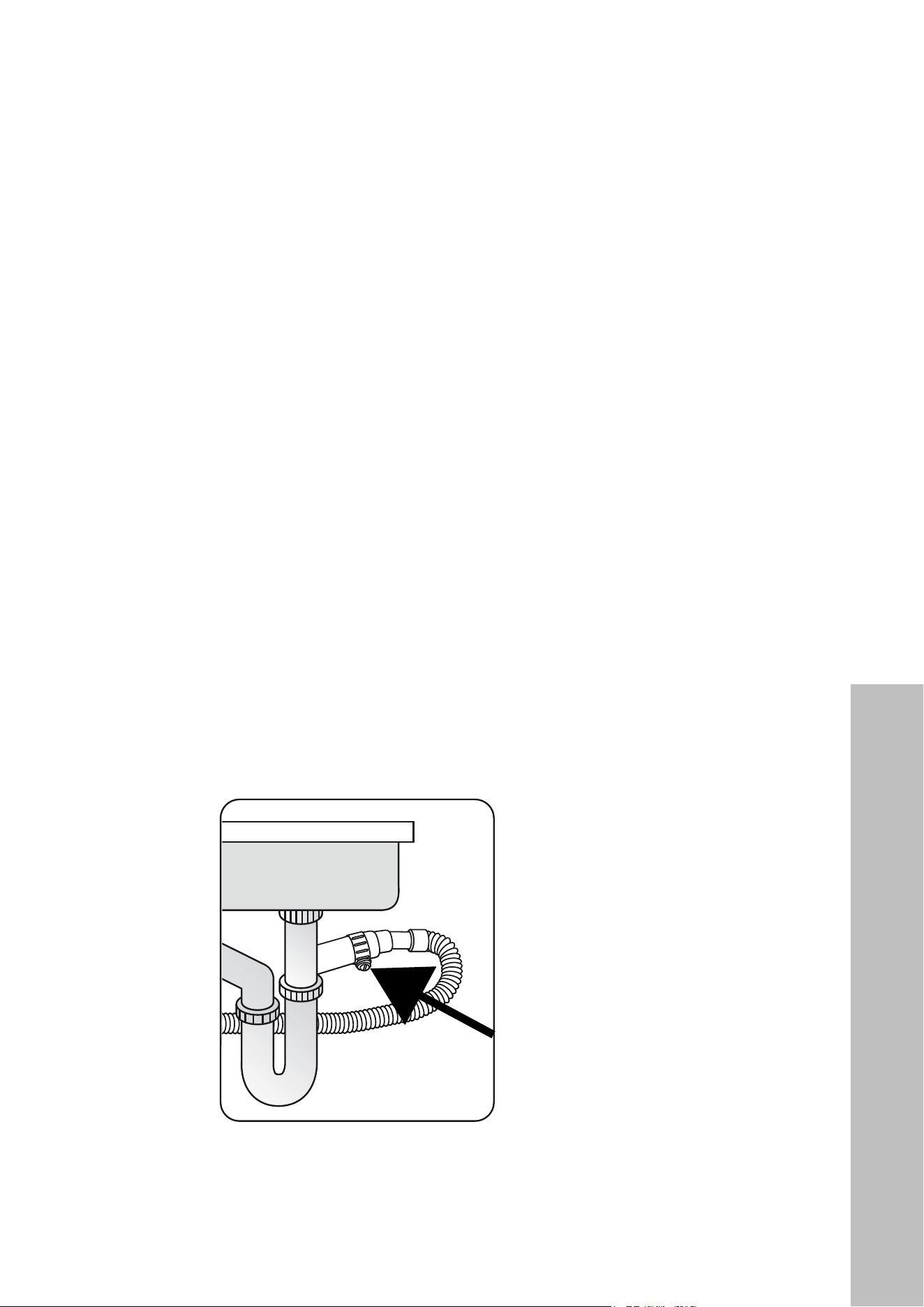
DRAIN HOSE CONNECTION
1. Check the parts on the sink where the drain hose will be connected.
2. There are several ways to insert the drain hose into the drain hose connector of the sink,
as shown in the following figures. Connect the drain hose in accordance with the water
pipe installation regulations in your region.
1716
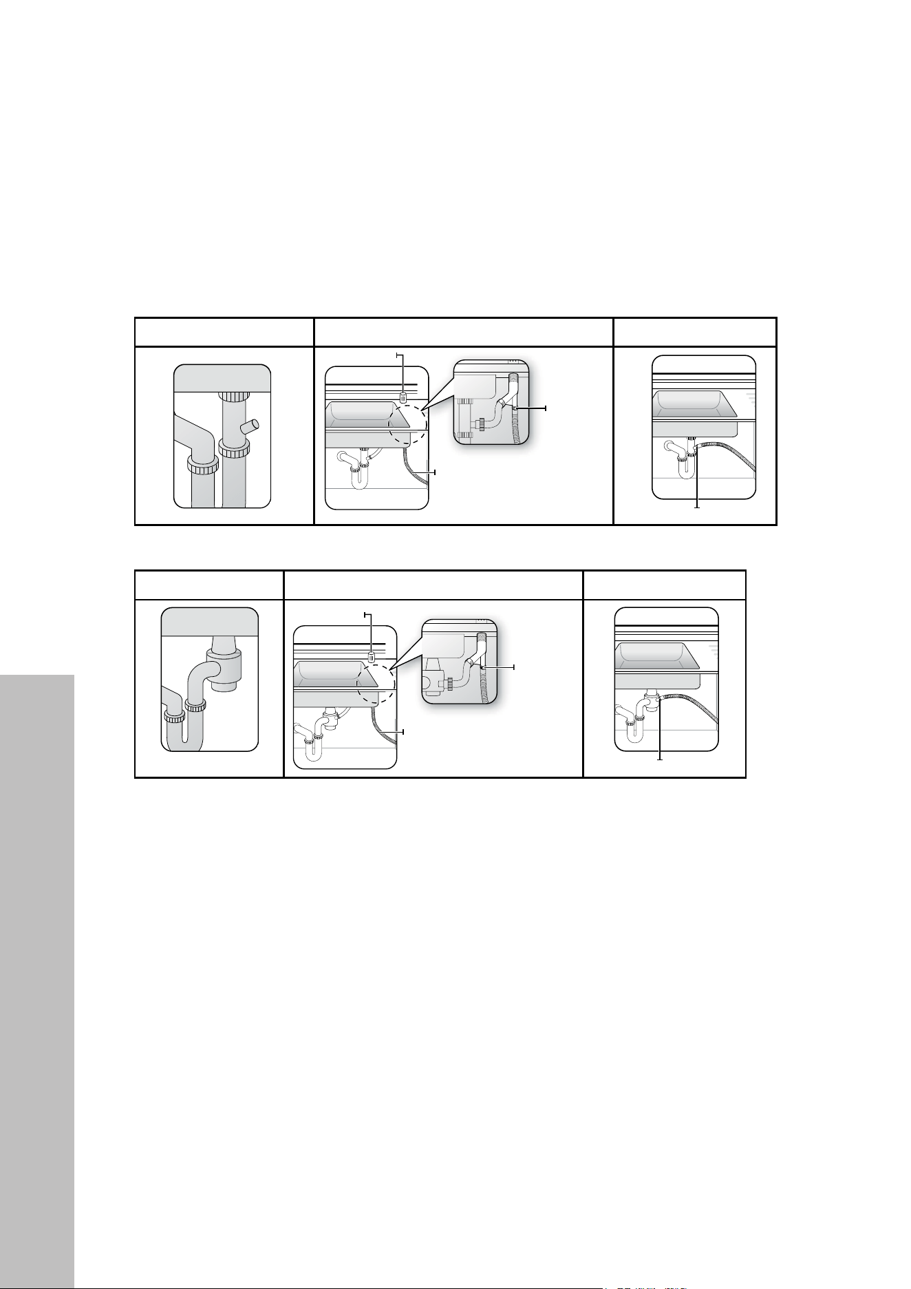
DRAIN HOSE CONNECTION
1. Check the parts on the sink to which the drain hose will be connected.
2. There are several ways to insert the drain hose into the drain hose connector of
the sink, as shown in the following figures. Connect the drain hose in accordance
with the water pipe installation regulations in your region.
No Garbage Disposal With an Air Gap Without an Air Gap
Garbage Disposal With an Air Gap Without an Air Gap
Hose clamp
Hose clamp
Air gap
Air gap
Hose clamp
Hose clamp
Drain hose
Drain hose
3. Check the size of the sink’s drain hose connector. If needed, cut the drain hose so
its end fits onto the sink connector (5/8", 3/4", or 1" - as shown below). If the
end of the drain hose does not fit onto the drain hose connector of the sink, use
an adapter, purchasable at a plumbing/hardware supply store.
4.
If necessary, cut off the
dotted line of the drain
hose to fit the size.
Slide a hose clamp over the end of the drain hose. Attach the drain hose to the
sink connector, slide the hose clamp to the end of the hose, and then tighten the
hose clamp.
Note: Use a hose clamp. Failure to do so may cause water leakage.
Use hose clamp for
drain hose assembly to
the sink.
Drain Hose Connection
Drain Hose Connection
INSTALLATI ON INSTALLATION
Tallac Dishwasher User Manual and Install Guide - English - August 2022 - PRINT.indd 16-17 8/26/22 1:59 PM
Hose clamp
Hose clamp
Drain house
Drain house
Drain Hose Connection
18
Drain Hose Connection
INSTALLATION
3. Check the size of the sink’s drain hose connector. If needed, cut the drain hose so its
end fits onto the sink connector (5/8", 3/4", or 1" as shown below). If the end of the
drain hose does not fit onto the drain hose connector of the sink, use an adapter (not
provided), available at any plumbing or hardware retailer.
4.
If necessary, cut off the
dotted line of the drain
hose to fit the size.
Slide the provided hose clamp over the end of the drain hose. Attach the drain hose
to the sink connector, slide the hose clamp to the end of the hose, and then tighten
the hose clamp.
NOTE: Failure to use a hose clamp may cause water leakage.
Use hose clamp for drain
hose assembly to the sink.
19
INSTALLATION
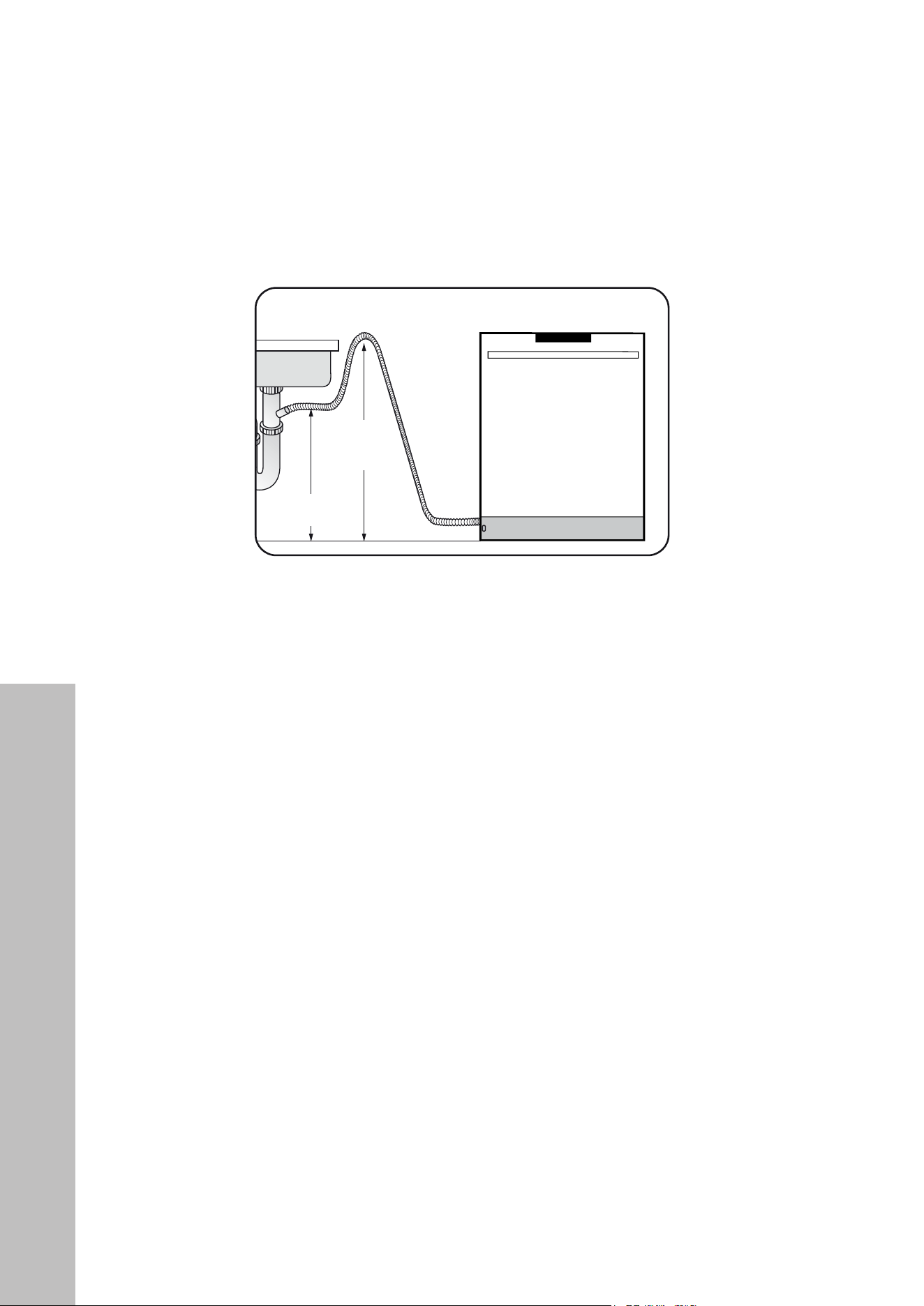
5. If there is no air gap, you can install a high loop. Hang the high point of the drain hose
as close as possible to the overflow level of the sink; this helps prevents backflow and
foul smells resulting from standing water. The high point should be at least 30" (762 mm)
from the cabinet floor, as outlined below.
Drain Hose
Min. 30"
(762 mm)
Min. 20"
(508 mm)
Sink
Dishwasher
6. When drilling a hole for the drain hose through an adjacent cabinet panel, use caution
to not cause damage to the drain hose by any sharp edges of the hole. If the panel is
wood, be sure to sand any rough edges before routing the drain hose through. If the
panel is metal, be sure to protect the drain hose by using a suitable edge protector or
grommet (not supplied) made for this purpose by the manufacturer.
7. Take caution not to damage the drain hose when installing the dishwasher on the floor,
wall, or cabinet. To prevent leaks or drainage problems, make sure the drain hose is not
damaged, kinked, or twisted.
8. IMPORTANT: Do not cut the wrinkled area of the drain hose to fit the size. When arranging
the drain hose, take caution not to touch the sharp edges of the cabinet or under-sink.
• Be careful when cutting off the end of the drain hose, as there is a risk of injury. Clean
around the sink’s drain connection so that it does not damage the hose. Inspect the inside
of the drain hose for any obstructions and remove if found. Also, inspect the outside
length of the drain hose for any damage, cuts, or excessive creases.
• When arranging the drain hose, make sure the drain hose is not cut, torn, or broken by
any sharp edges of the floor, the product itself, or the cabinet. A damaged drain hose
may cause water leaks.
Drain Hose Connection
20
Adjusting the Kick Plate
ADJUSTING THE KICK PLATE
Once the dishwasher is successfully installed, attach the kick plate to the unit. The two-piece
kick plate can be adjusted to the height and depth needed for the kitchen.
DWV-18
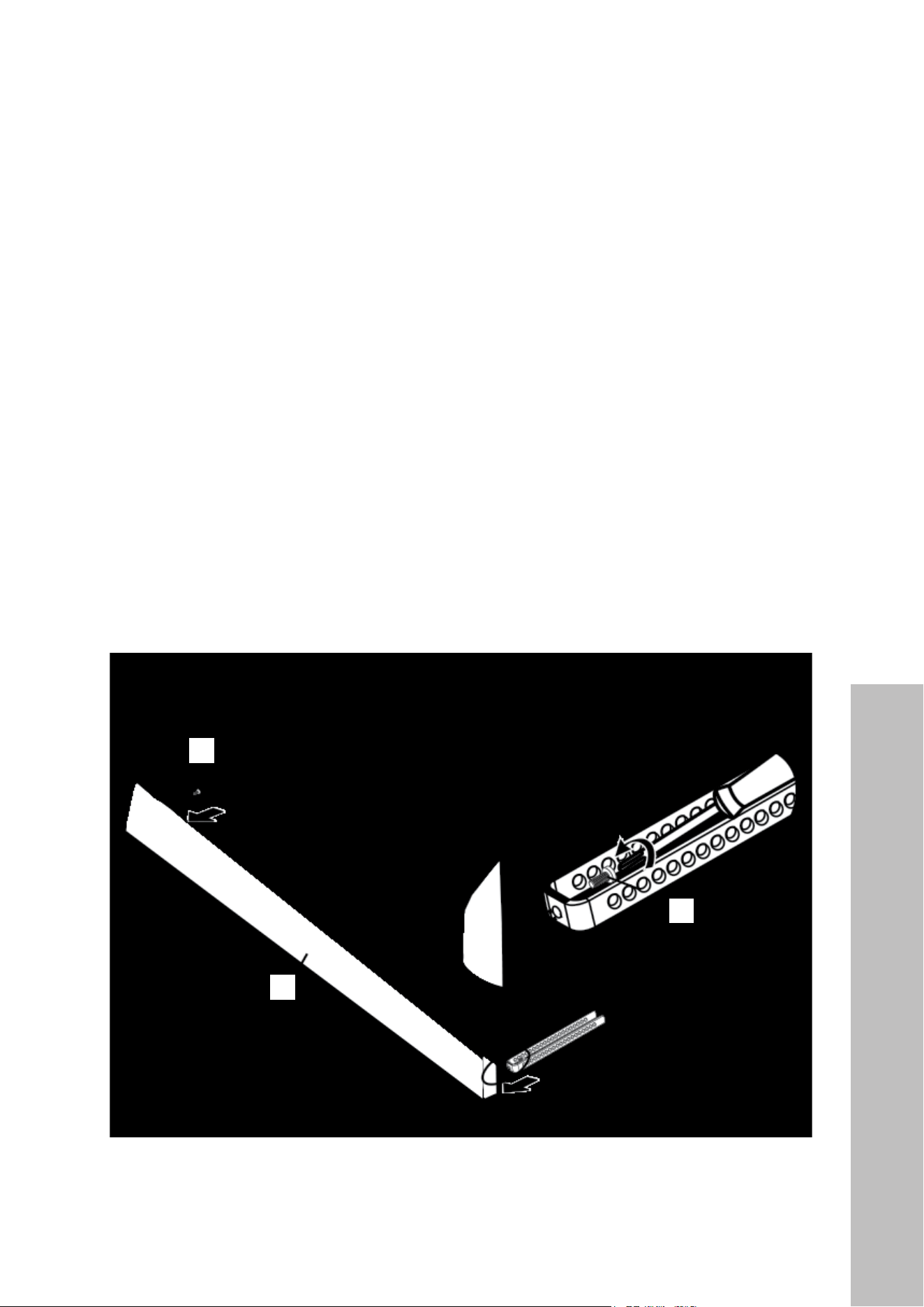
1. If the installed height of the dishwasher is above 32 1/8" (816 mm) using the short front
leg supports, install the metal back plate (letter "p" from the parts list on page 8) at
5 1/4" (133 mm) height. Using a Phillips-head screwdriver, secure the back plate to the
two kick plate brackets (l) using the 5/32" x 7/32" screws (m).
DWV-24
1. If the installed height of the dishwasher is above 34" (864 mm) using the short front leg
supports, install the metal back plate (p) at 5 1/4" (133 mm) height. Using a Phillips-
head screwdriver, secure the back plate to the two kick plate brackets (l) using the
5/32" x 7/32" screws (m).
p
l
m
INSTALLATION
21
2. Depending on the overall height required to cover the remaining gap, the plastic plinth
panel (o) height can be adjusted in 3/8" (10 mm) increments by removing/adding
each section. It is attached through the side holes of the metal back plate and secured
using the U-shaped clips (n) to hold the pegs.
o
o
n
The metal back plate and adjustable plinth panel should be assembled with the kick plate
brackets mounted as shown in the diagram below.
q
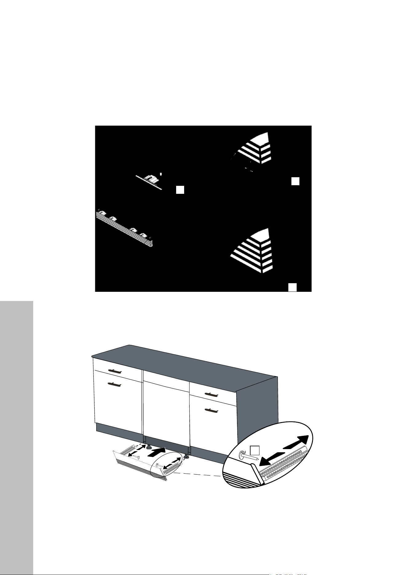
3. Depending on the desired cabinet depth, the kick plate brackets' depth can be set using
the stopper pins (q) inserted into the holes.
4. The panel assembly should be inserted into the corresponding rectangle slots above
both the front support legs.
INSTALLATION
Adjusting the Kick Plate
22
Panel Installation
INSTALLATION
INSTALLING THE OUTER PANEL
After the dishwasher is properly connected to water and electrical and is installed into your
cabinet cutout, the final step is to secure the outer panel onto the dishwasher door.
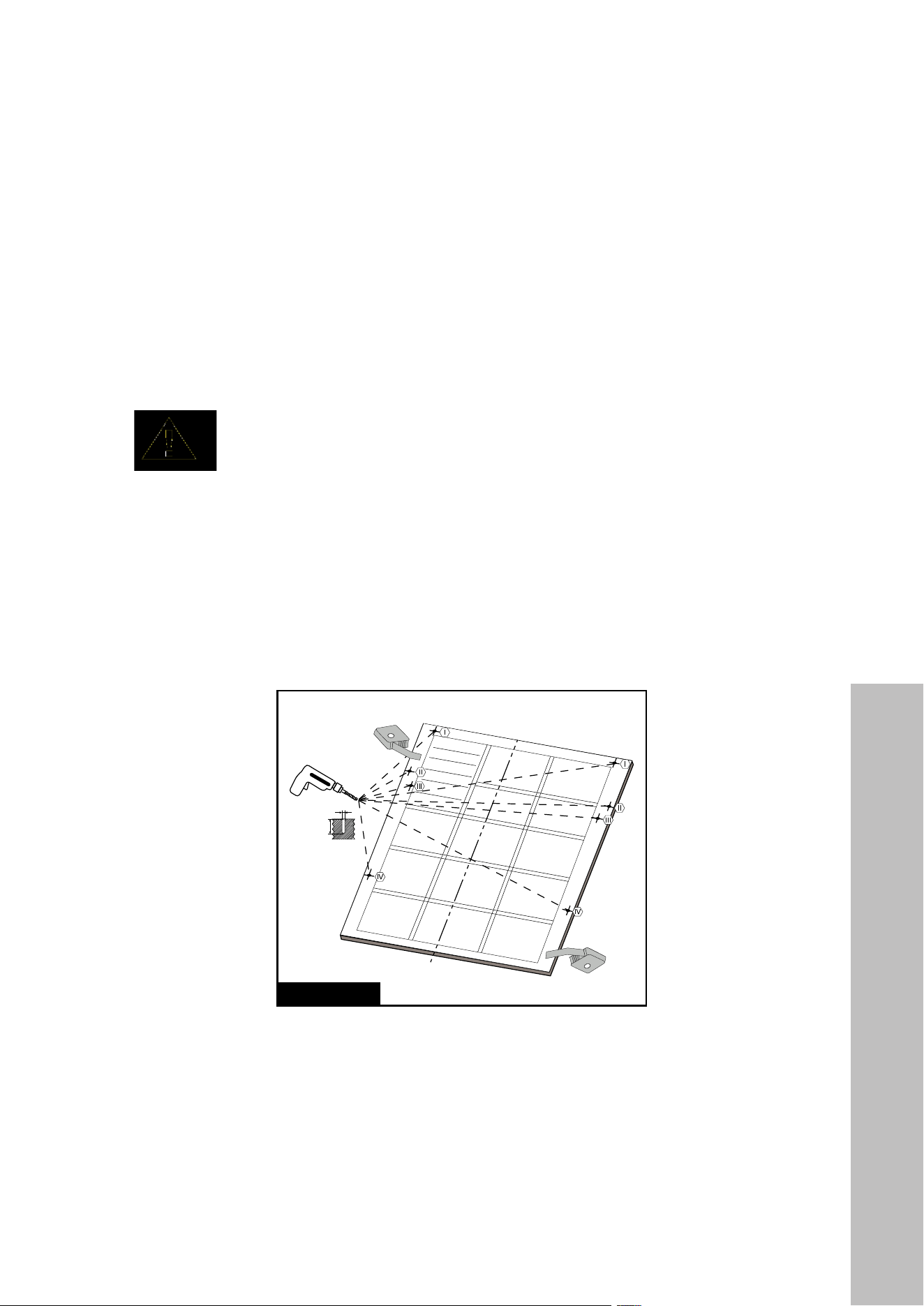
1. If necessary for a custom outer panel, affix the panel mounting template provided with
the appliance to the inside of the outer panel, making sure the template is straight so the
drill holes line up.
NOTICE
After drilling holes as noted on the mounting template, remove the template
before completing installation onto the dishwasher door.
2. As shown in Figure A, drill each screw hole into the inside of the outer panel using the
points marked on the template, making sure not to drill deeper than 15/32" (12 mm).
• Diameter of Drilling Bit: 5/64" (2 mm)
• Depth of Drilling Bit: 15/32" (12 mm)
FIGURE A
FIGURE B
Ø 5/64" (2 mm)
Ø 15/32" (12 mm)
k
k
e
d
1 9/16" (40 mm)
2 3/16" (55 mm)
NOTE: The use of the outer panel mounting template only applies to custom door panels
supplied by the customer. ZLINE-provided outer panels are pre-drilled and therefore do not
require the template to install.
23
Panel Installation
INSTALLATION
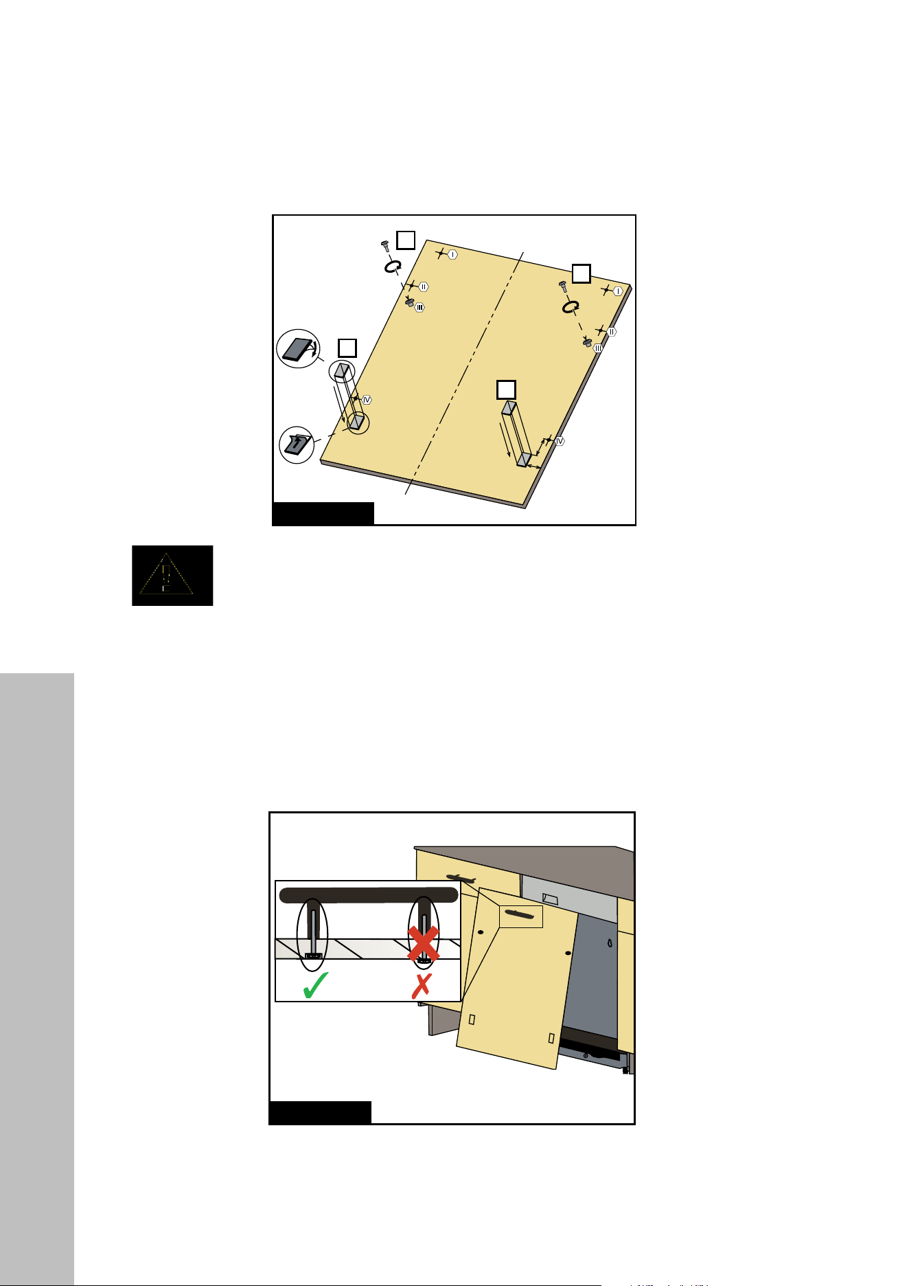
3. As shown in Figure B, fasten Mount Screws Ø 5/32" x 27/32" (k) into positions III.
4. As shown in Figure B, install both Adhesive Panel Strips (d and e).
FIGURE A
FIGURE B
Ø 5/64" (2 mm)
Ø 15/32" (12 mm)
k
k
e
d
1 9/16" (40 mm)
2 3/16" (55 mm)
NOTICE
Before attaching Adhesive Panel Strips, remove the white protective sheets.
These Velcro strips are meant to help hold the outer panel in place while you
fasten it to the dishwasher door.
5. Before mounting the outer panel onto the dishwasher door, mount the handle on the
panel as shown Figure C. NOTE: The handle screws must be flush mounted below
the inside mating surface of the outer panel so that the panel can sit flush against the
dishwasher door.
FIGURE C
FIGURE D
FIGURE E
FIGURE F
g
I
7-13 lbs (3-6 kg)
7 lbs
(3 kg)
min 6
4X
13 lbs
(6 kg)
II
III
IV
V
24
Panel Installation
INSTALLATION
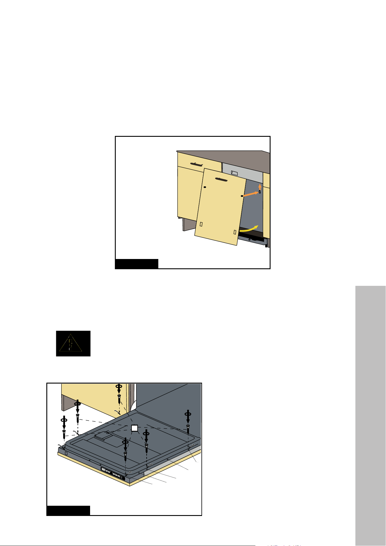
6. The upper section of the outer panel can be secured by the two mount screws (k) fastened
in step 3 by sliding the panel upward after aligning those screws with the corresponding
keyholes on the dishwasher door, shown with the orange arrows in Figure D. Slide the
panel upward until the top edge is flush with the top of the dishwasher control panel.
Once secure, the panel can swing closed, shown with the yellow arrow in Figure D.
FIGURE C
FIGURE D
FIGURE E
FIGURE F
g
I
7-13 lbs (3-6 kg)
7 lbs
(3 kg)
min 6
4X
13 lbs
(6 kg)
II
III
IV
V
7. With the outer panel now attached to the dishwasher door, fully open the door and, as
shown in Figure E, fasten Screws Ø 5/32" x 1 5/8" (g) into the six positions (I, III, and
V) on the inside of the dishwasher door into the pre-drilled holes on the panel.
NOTICE
Before mounting Screws Ø 5/32" x 1 5/8" (g), the existing screws in
positions I, III, and V on the door must be removed.
Scan the QR code
for a door panel
installation tutorial.
FIGURE C FIGURE D
FIGURE E
FIGURE F
g
I
7-13 lbs (3-6 kg)
7 lbs
(3 kg)
min 6
4X
13 lbs
(6 kg)
II
III
IV
V
25
Panel Installation
INSTALLATION
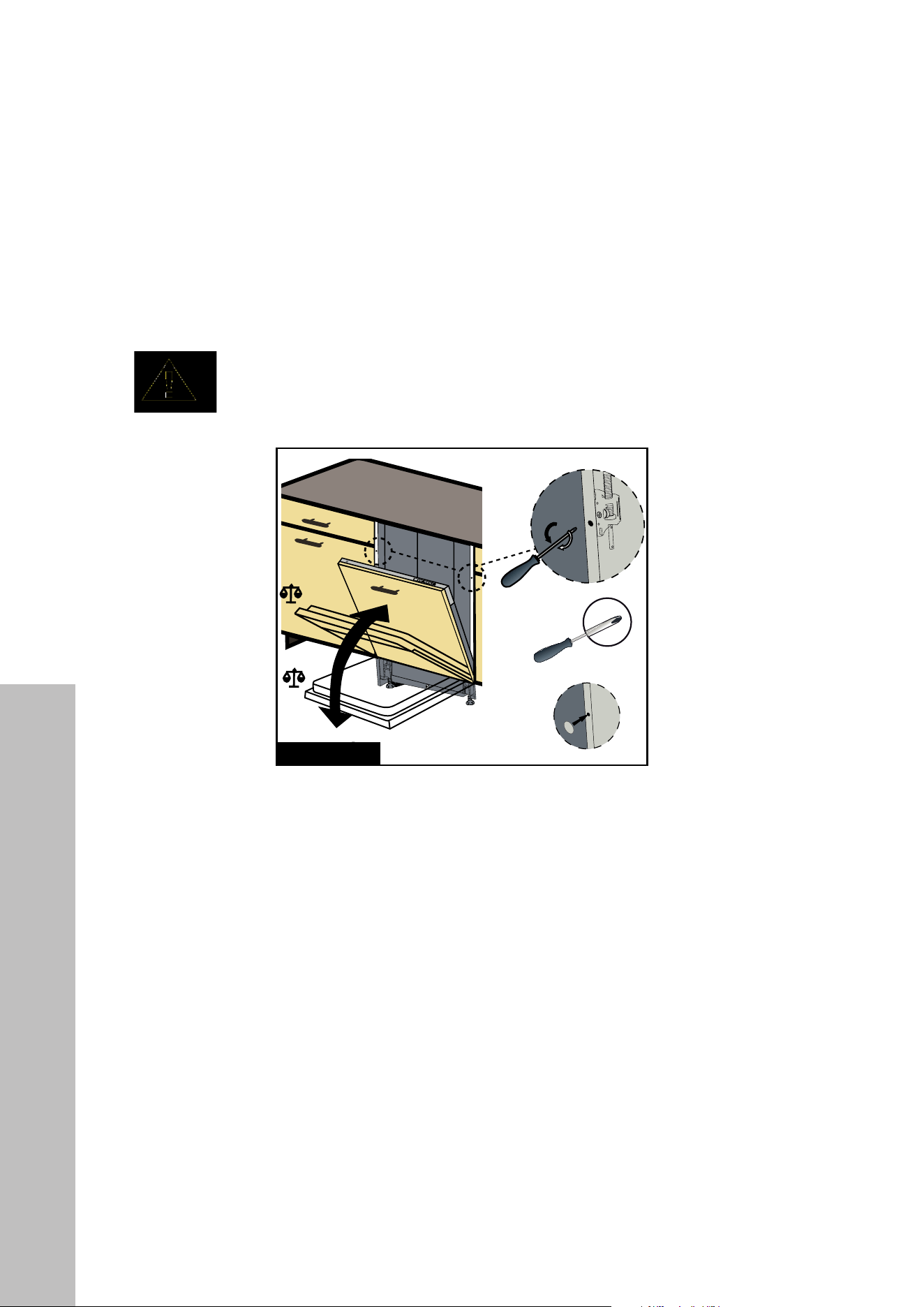
8. Depending on the weight of the assembled outer panel, the door spring tension can be
adjusted by the mechanism shown in Figure F.
• If the door is falling down, the mechanism must be turned clockwise in the direction
of the white arrow with a Phillips screwdriver.
• If the door is swinging upwards, the mechanism must be turned counter-clockwise
in the direction of the black arrow with a Phillips screwdriver.
NOTICE
Minimum Phillips screwdriver diameter is 15/64" (6 mm) for this application.
FIGURE C FIGURE D
FIGURE E
FIGURE F
g
I
7-13 lbs (3-6 kg)
7 lbs
(3 kg)
min 6
4X
13 lbs
(6 kg)
II
III
IV
V
9. After adjusting the door tension, the holes can be covered with the four provided adhesive
hole covers (f).
10. Mounting brackets previously fixed to the dishwasher are also fixed in the cabinetry with
Screws Ø 5/32" x 19/32" (h).
11 . Check whether the bottom of the door hits the toe kick of the kitchen cabinet.
• If the door hits the toe kick, cut the necessary section out of the toe kick.
• Apply silicone, sealant, or paint to the cut edge of the kitchen cabinet toe kick so
it does not absorb moisture.
Scan the QR code for a door spring tension tutorial.

26
Installation Checklist
INSTALLATION
INSTALLER CHECKLIST
The professional who installs this appliance must complete and check the following:
• The dishwasher is square and level.
• The dishwasher is fastened securely to the cabinetry.
• The dishwasher door opens and closes freely. The dishwasher door must close without
hitting any cabinetry or countertop.
• The inlet water supply is turned on and checked for leaks.
• The drain hose has been connected and checked for leaks. There must be no kinks or
obstructions in the drain hose.
• The drain hose must be installed with a 30" (762 mm) high drain loop for drain hook-ups
without any air removed.
• The spray arms are free and rotate freely.
• The rinse cycle has been run.
• The water level must be below the filter screen after the end of the wash program. It is
normal to find some water in the drain filter area.
NOTE: If the installer connects the water drain hose to a trap spigot under the sink, the plastic
membrane must be removed. If the entire membrane is not removed, remaining food can
cause a blockage in the drain hose spigot. Ensure a hose clamp is used to secure the hose
to the spigot.
FINAL INSTRUCTIONS
1. Press the On/Off button to turn the dishwasher on.
2. Power indicator light comes on.
3. Use the Program Select button to choose a washing program.
4. Start the program with the Start/Pause/Cancel button.
5. Run the dishwasher through one complete cycle. When the wash cycle is completed, use
the On/Off button to turn the dishwasher off.
6. If the dishwasher does not operate properly, refer to the Troubleshooting section.
• If the unit does not operate properly after following these steps, contact ZLINE at
1-614-777-5004 to schedule an authorized service agent to inspect the new dishwasher
for any function related failure.
• The manufacturer warranty does not cover installation, conversion, or customer education
service visits.

WARRANTY
COVERAGE
ZLINE Kitchen and Bath (“ZLINE”) dishwashers have a one year parts and service warranty.
ZLINE warranty periods begin from the original date of product delivery and solely cover the
original purchaser of the product, delivered new and in its original carton. The limited warranty
covers all parts and labor for necessary repairs if any part of the product, or the product itself,
proves to be defective in materials or workmanship. The product must be deemed serviceable
via troubleshooting with the ZLINE Customer Experience team. All service on ZLINE products
under warranty must be performed by ZLINE-approved and ZLINE-certified service providers
unless otherwise specified by ZLINE. Service will be provided during normal business hours.
Products must be unobstructed and accessible to the service provider at the time of service.
ZLINE’s liability is limited to the original purchase price of the product. Additional injuries,
losses, damages, or other inconveniences caused by product malfunction or defects in materials
are not covered under the terms of this warranty.
TERMS
ZLINE warranties apply only to the original purchaser of a ZLINE product installed for normal
residential use. This is defined as a single-family, residential dwelling in a non-commercial
setting. Any warranty claim stemming from installation, operation, or any other use within a
commercial setting is not covered under this limited warranty. Commercial settings include,
but are not limited to: schools, churches, hotels, restaurants, vacation rentals such as Airbnb,
daycare centers, private clubs, fire stations, common areas in multi-family dwellings, nursing
homes, food service locations, and institutional food service locations such as hospitals or
correctional facilities.
This warranty is non-transferable and will not under any circumstance be extended based on
the date of installation — the warranty period takes effect from the date of delivery and only
covers the original purchaser. The warranty applies only to products installed in the contiguous
United States and the District of Columbia. Failure to secure certified warranty service per these
terms will result in a forfeiture of the remaining warranty.
Out-of-pocket payments will not be reimbursed unless prior approval is received from ZLINE
and/or ZLINE-certified service contract partners. Unapproved out-of-pocket payments
for service will not be reimbursed. All warranty procedures must be followed to maintain
warranty coverage.

WARRANTY
If a product qualifies within the service window provided under these warranty terms, and ZLINE
is unable to repair the product or a defective part of the product after a reasonable number
of attempts, ZLINE reserves the right to offer to replace the defective part or the product or
provide the original purchaser a full refund of the purchase price of the product (not including
installation, removal, or other charges that were not included in the original purchase price).
The original purchaser of the product must provide the original proof of purchase, including the
purchase date, when filing a claim to obtain replacement parts, service, or refunds. Additionally,
the original purchaser of the product must provide the serial number of the product when filing
a claim to obtain replacement parts, service, or refunds.
This warranty shall not apply to any ZLINE product in which the original factory serial
number has been removed, altered, or cannot be readily determined for any reason. Further,
ZLINE is not responsible for damage resulting from, but not limited to: shipment, delivery, or
improper installation; negligence or improper maintenance, misuse, or abuse of the product;
unauthorized alteration, modification, or tampering with the product; accident, fire, floods,
pest infestations, pandemics, natural disasters, or any other unpreventable or unexplained
acts of nature, commonly referred to as “acts of God”; flare-up fires or damages caused by
improper electric supply, electrical line current, voltage, or power surges; and service to correct
installation not in accordance with the instructions contained in ZLINE’s product manuals and/
or with local government codes.
This warranty does not apply to aesthetic damage, scratches, or natural wear caused by normal
use; second-hand, open box products, or products purchased from an unauthorized retailer;
and damages or issues stemming from alteration or tampering with the dishwasher, including,
but not limited to, painting any portion of the product’s interior or exterior and altering or
otherwise manipulating the power cord.
In the event service is dispatched, and it is discovered that the reported issue is not covered
under warranty based on the disclaimers above, the customer will be responsible for all service
fees. Failure to pay these fees will result in the forfeiture of remaining warranty coverage.

WARRANTY
Information contained within ZLINE’s installation and user manuals, in addition to product
information included on ZLINE’s website and all related digital listings, do not cover every
possible condition and situation that may occur during the installation or operation of
ZLINE products.
ZLINE reserves the right to make changes at any time to its products when considered safe,
necessary, and useful. Always check the ZLINE website for the most up-to-date version of its
product manuals: www.zlinekitchen.com/pages/manuals.
Do not install or operate any ZLINE product if it has missing or broken parts or if it arrives
damaged due to shipping. If ZLINE products arrive damaged, contact ZLINE Customer
Experience at 1-614-777-5004 for help. Failure to report a damaged appliance prior to
installation or operation may void the warranty.
ZLINE disclaims responsibility for damage or injury caused by improper installation or use of
any of its products. ZLINE is under no obligation, by law or otherwise, to provide concessions,
including repairs, prorates, rebates, discounts, or replacements, once the warranty has expired.
SERIAL NUMBER LOCATION
Please write down the model number and serial number of
your appliance. Both numbers are located on the rating tag
located on the right-hand side of the inner door of the
dishwasher. The tag is visible when the dishwasher door is
open. Do not remove permanently affixed labels, warnings,
or plates from the product. This will void the warranty. You
may also consider attaching your receipt or proof of purchase
to this manual.

WARRANTY
SERVICE
For warranty service, please contact our Customer Service team at
1-614-777-5004 or visit www.zlinekitchen.com/contact to utilize our
online Customer Experience Portal.
Scan the QR code to view the most up-to-date version of our Installation
Manual and User Manual.
Need to purchase a part or accessory for your ZLINE product?
Visit www.zlineparts.com, ZLINE's official parts distribution partner.