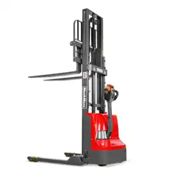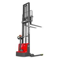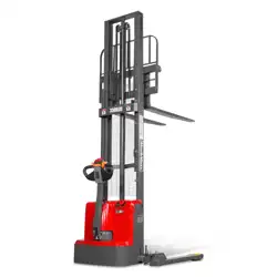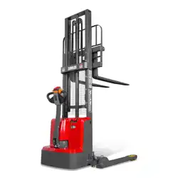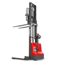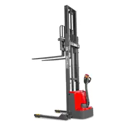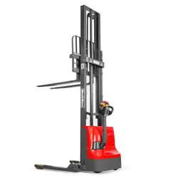
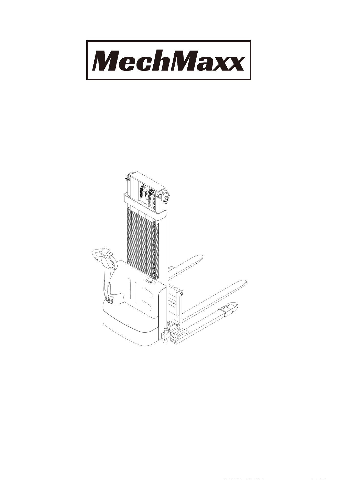
F26 Series
Electric Pallet Stacker
Maintenance & Use Instruction
Warning! Please read this manual carefully before
using this device.
Warning! Do not enable this function when all
components are not fully installed with this device.

CONTENT
1. Product Introduction ..................................................................................1
2. Correct use..................................................................................................2
3. Model Introduction.................................................................................... 3
3.1 Model Overview .......................................................................................3
3.2 Schematic diagram and parameters of the vehicle.................................... 3
4. Schematic diagram of control mechanism................................................... 6
5. Working Principle....................................................................................... 7
5.1 Walking system ........................................................................................7
5.2 Steering System ........................................................................................7
5.3 Braking structure and braking schematic diagram .....................................7
5.4 Operating System .....................................................................................8
5.5 Electrical System ......................................................................................8
5.6 Hydraulic system............................................................... ....................... 9
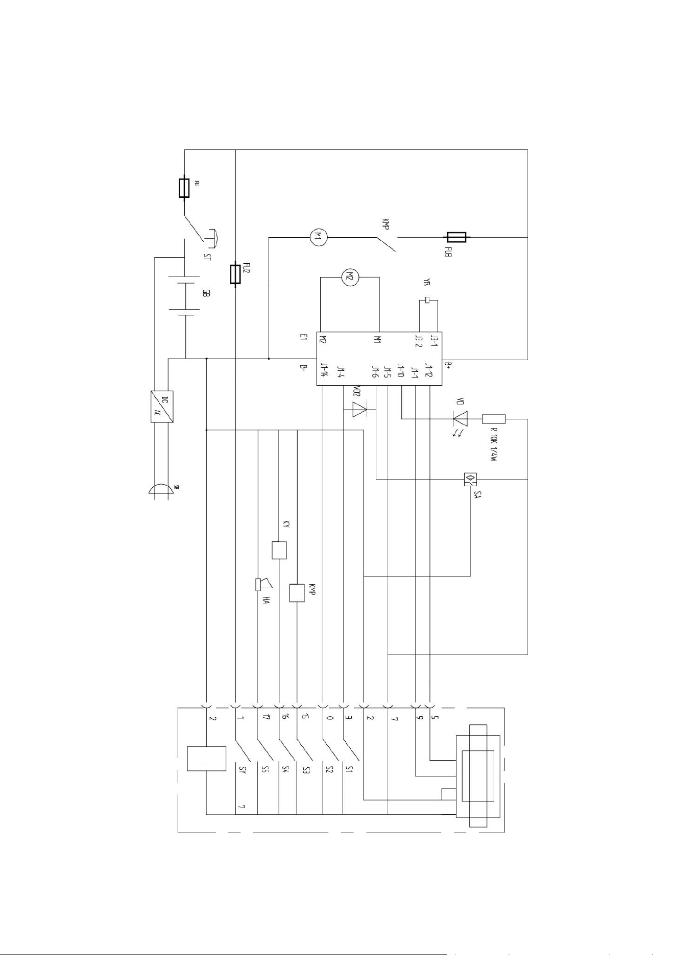
6. Electrical schematic Diagram .....................................................................10
7. hydraulic schematic diagram .....................................................................11
8. operation rules.........................................................................................12
8.1 Starting, running and stopping............................................................... 12
8.2 Use of emergency power off safety switch..............................................12
8.3 Use of horn and reversing horn ..............................................................12
8.4 Battery Capacity Display .........................................................................13
8.5 Handling and Stacking Operations ...........................................................13
9. Maintenance and Maintenance Instructions .............................................14
9.1 Safety regulations for repair and maintenance ........................................14
9.2 Routine Maintenance ..............................................................................15
9.3 Professional Maintenance Manual ..........................................................15
9.4 Battery maintenance, charging and maintenance ....................................19

10. Safety Precautions.................................................................................. 22
10.1 General Rule .........................................................................................22
10.2 Transportation and Storage................................................................... 22
10.3 Check before use ..................................................................................23
10.4 Safe Operations ....................................................................................23
11. Troubleshooting.......................................................................................26
11.1 Fault Diagnosis .....................................................................................26
11.2 Preparatory work before repair........................................................... 26
11.3 Check the amount of hydraulic oil ....................................................... 27
11.4 Preparation work after maintenance and before use............................27
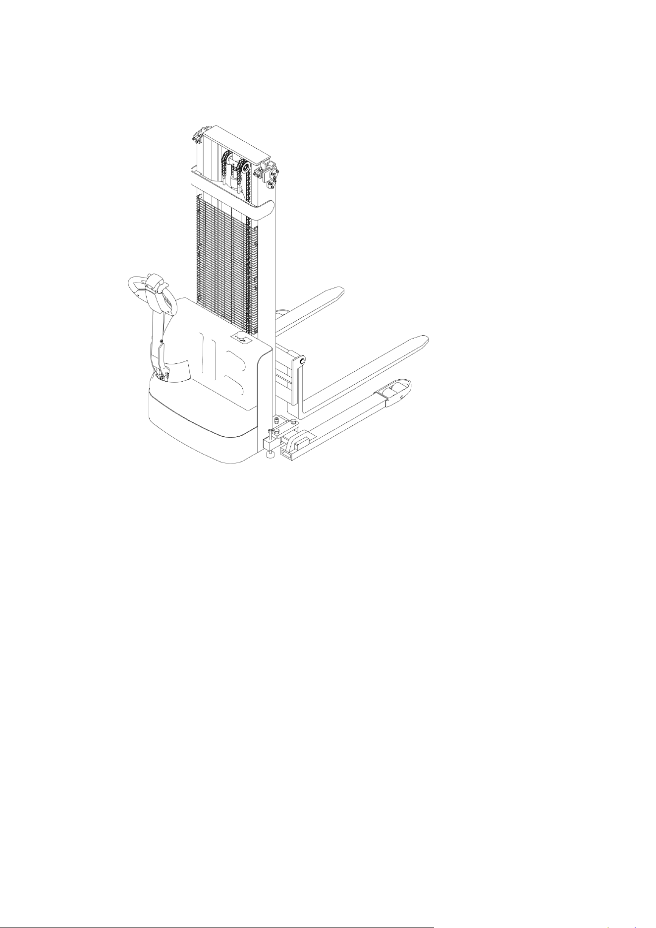
1
1. Product introduction
F26 type battery pallet stacker, this stacker adopts advanced structure such as wide
view lifting system, new DC controller, and equipped with high quality motor, traction
battery and high-power pump station motor. Therefore, it has superior performance,
convenient operation, wide field of vision, flexible steering, reliable braking, good power
performance, less noise, no pollution, beautiful appearance and so on.
The truck is suitable for stacking and handling goods on hard and flat ground.
Use environment:
A. The altitude does not exceed 1200 meters;
B. Indoor at room temperature of +5°C to +40°C;
C. When the ambient temperature is +40℃, the relative humidity shall not exceed
50%. When the ambient temperature is relatively low, the relative humidity shall be
relatively high;
D. Hard, flat ground.
E. Do not use the vehicle in inflammable, explosive, acid, alkali and other corrosive
environment.

2
2. Correct use
Only use this battery pallet stacker in accordance with this instruction manual.
The forklift truck described in this manual is a self-propelled battery pallet stacker with
operating handle button to control the lift of the forklift truck.
Improper use may result in personal injury or machine damage. The
operator/operator company shall ensure proper use and that the forklift is operated only
by trained and authorized personnel.
The forklift should be used on a firm, flat, intact surface and suitable surface. The
vehicle is designed to be indoors at +5°C to +40°C
Use under light load without crossing permanent obstacles or potholes. It is forbidden
to operate on the ramp. The cargo must be placed approximately at the center of the load
of the forklift.
Lifting or carrying personnel is strictly prohibited. If carried, the cargo must be lowered
to lift point.
Do not use this truck on tailgate or loading ramp.
Rated loads are marked on capacity labels and nameplates, and operators must pay
attention to these warning labels and safety instructions.
Operating lighting must reach a minimum of 50 lux.
Any modification or alteration that may affect the rated load, stability or safe operation
of the vehicle shall be subject to prior written approval of the vehicle's original
manufacturer or its authorized manufacturer or its successors. This includes the effects of
changes such as increased braking, steering, visibility and removable accessories.
Capacity nameplates, labels, identification marks, operation and maintenance
manuals are subject to modification or change approved by the manufacturer or its
successors.
Failure to follow these instructions will result in loss of warranty for vehicle damage.
3
3. Model introduction
3.1 Model Overview
This manual is a collection of F26 light 1.2 ton electric stacker (hereinafter referred to
as "stacker").
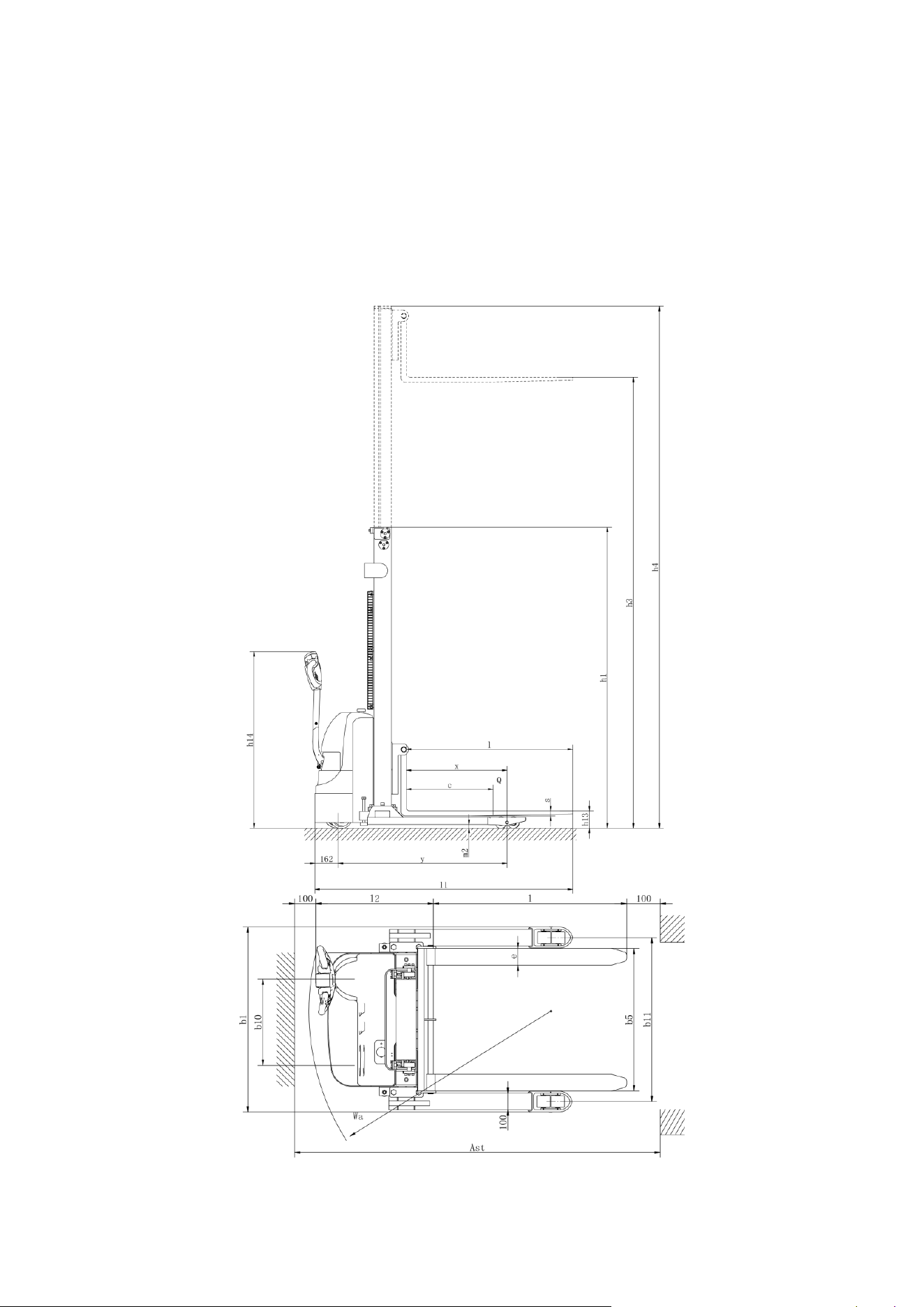
3.2 Schematic diagram and parameters of the vehicle

4
Model
F26-98S
F26-118S
F26-138S
Drive
Battery
Mode of operation
Pedestrian
Rated load capacity
Q (lbs)
2640
Load center distance
c (in)
23.6
Front suspension
x (in)
27.5
Wheel base
y (in)
46
Service weight (including battery)
Lbs
1390
1420
1450
Tire type
Polyurethane(PU)
Driving wheel size
Φ×w(in)
Φ8.3×2.8
Bearing wheel size
Φ×w(in)
Φ3.2×2.8
Balance wheel size
Φ×w(in)
Φ5.9×2.3
Wheel base, driving end
b
10
(in)
18.3
Wheel base, bearing end
b
11
(in)
40.3-56.1
Minimum gantry height
h1 (in)
72
81.9
91.7
Lift height
h3 (in)
98.4
118.1
136.2
Maximum gantry height
h4 (in)
120
139.7
159.4
Height of handle in drive position min/max
h
14
(in)
34.3/47.2
Lowered fork height
h
13
(in)
2.6
Overall length
l
1
(in)
70.2
Body length
l2 (in)
25
Adjustable legs
b
1
/ b
2
(in)
45.2-61
Fork size
s/e/l (in)
1.4/3.9/45.3
Overall fork width
b5 (in)
8.3-33.5
Ground clearance at wheelbase center
m
2
(in)
1

5
Channel width: 1000x1200 pallet (1200
cross)
Ast (in)
87
Channel width: 800x1200 pallet (1200
placed along the fork)
Ast (in)
85.8
Turning radius
Wa (in)
52.8
Walking speed, laden/unladen
(mph)
2.5/2.6
Lifting speed, laden/unladen
(mm/s)
92/136
Lowering speed, laden/unladen
(mm/s)
112/98
Maximum gradeability, laden/unladen
(%)
6/8
Brake type
electromagnetic brake
Drive motor power
(kW)
0.75
Lifting motor power
(kW)
2.2
Battery voltage / capacity
(V/Ah)
24/60 Li-ion
Battery weight (± 5%)
(lbs)
2×60
Driver control type
Dc speed control
Noise level
(dB(A))
≤70
Steering type
Mechanical steering
6
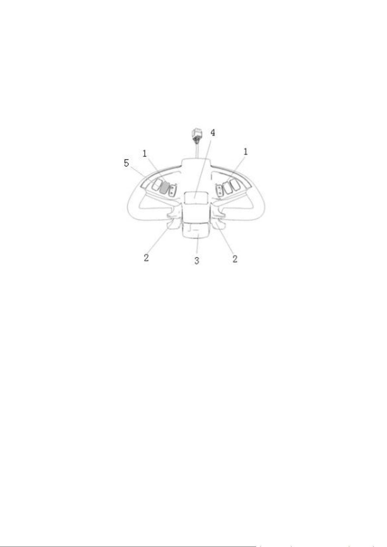
4. Schematic diagram of control mechanism
Stacker takes battery as power source, uses electrical and hydraulic control to realize
walking, forklift and other actions. The basic structure is shown below. Schematic diagram
of operating mechanism:
1. Lift down button 2. Run switch 3. Belly switch 4. Horn button 5. Electric meter

7
5. working principle
5.1 Walking System
The stacker's movement is powered by the battery and achieved by controlling the
DC motor on the driving wheel. The DC motor converts the high speed and low torque into
low speed and high torque through the gear reduction box, and finally the drive wheel
performs the action. The speed of walking is realized by frequency conversion control of
motor speed, which is controlled by the accelerator.
The gearbox is supplied with sufficient gearbox oil at the time of shipment. Under
normal conditions, change the gearbox oil every 1000 hours of use.
In the process of use, if you hear abnormal sound from the gear box, you should stop
and check immediately to determine whether the bearing is damaged or the gear has
problems. Only after replacement and repair can you continue to use it.
5.2 Steering System
The steering of the stacker is realized by the operating handle through the handle rod
and driving motor.
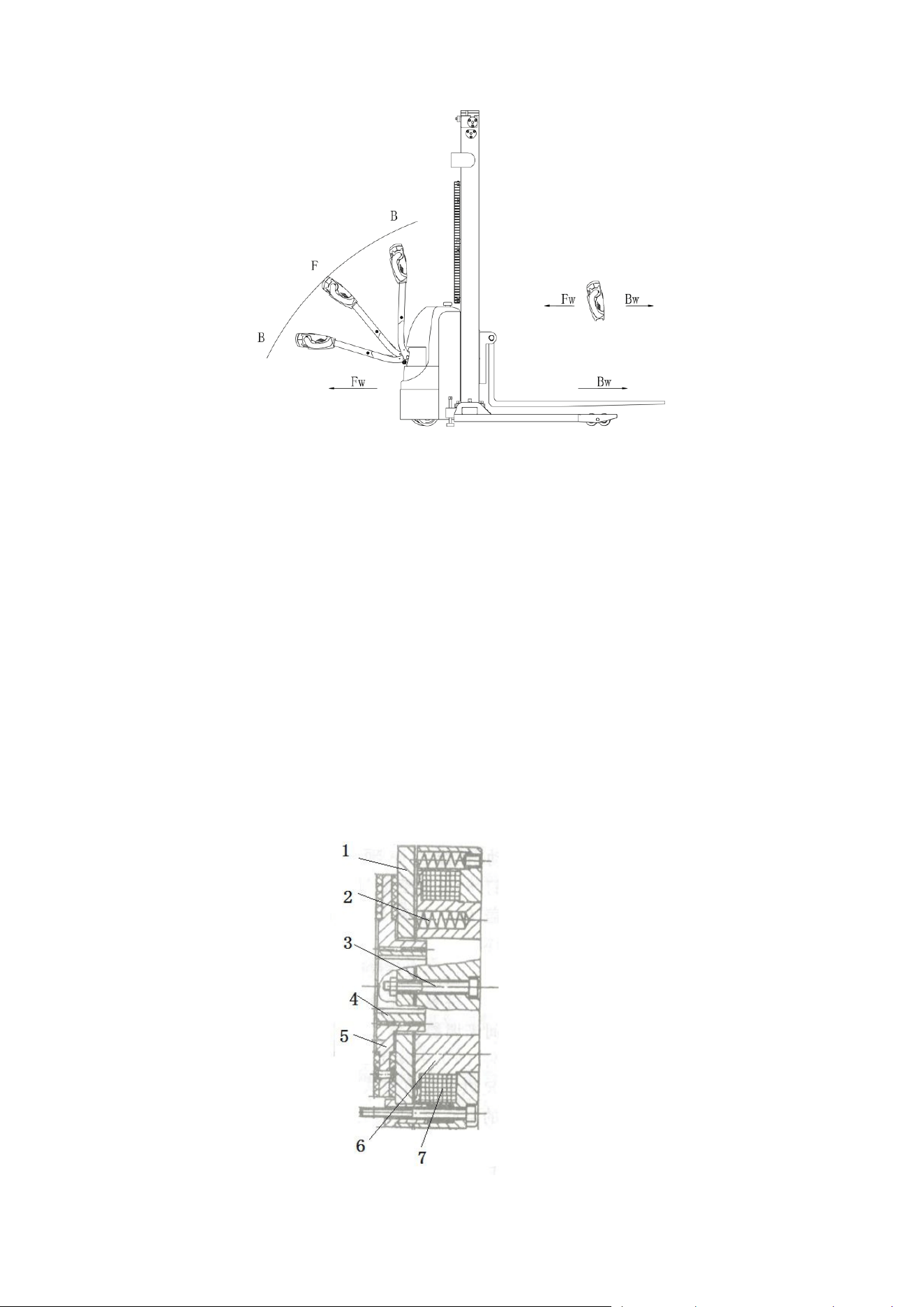
5.3 Braking structure and braking schematic diagram
Braking performance depends on road conditions and vehicle load conditions.
5.3.1 The braking function can be activated in the following ways:
L By turning the drive switch (2) to the '0' position or releasing the switch, the vehicle
will brake until it stops.
L By driving switch (2) from one drive direction directly to the opposite direction, the
vehicle regenerative braking until it begins to enter the opposite direction.
L The handle moves up and down to the braking area (' B ') and the vehicle brakes.If
the handle is released, the handle will automatically move up to the upper braking area ('
B ') and the vehicle will brake until it stops.
L Belly switch (3) prevents the operator from being squeezed and when the vehicle is
moving in the direction of (' Fw ') meets an obstacle, the body touches the belly switch
vehicle to slow down or start moving towards (' Bw ') for a certain distance and then stop.If
the handle is in the operating area and the vehicle is not moving, consider that this button
is still in effect.
8
5.3.2 Brake working principle:
The brake is composed of magnetic yoke assembly 6, excitation coil 7, spring 2,
brake disc 5, armature 1, gear sleeve 4, mounting screw 3, etc.The brake is mounted on
the end cover of the motor and the mounting screws are adjusted to the specified air gap
value.The gear sleeve is fixed on the shaft, and its outer teeth are matched with the inner
teeth of the brake disc to transfer torque when working, and the brake disc can move
axially on the gear sleeve.
When the brake's excitation coil 7 is energized, the coil generates a magnetic field
that pulls the armature 1 toward the magnetic yoke assembly 6, and the armature 1
disengages (releases) the brake disc 5.Then the motor drive shaft with brake disc 5
normally start and run.When coil 7 is powered off, magnetic flux disappears, armature 1 is
released, spring 2 presses on armature 1, compacts the friction plate on the brake disc,
generates friction and achieves braking purpose.
Braking schematic

9
5.4 Operating System
The main working mechanism of the stacker is the fork, which carries pallets or goods
and carries them for short distance transportation. The expansion of the cylinder is
controlled by the operating handle, and the pressure oil is provided by the pump station.
A slow drop valve is installed in the loop of the lifting cylinder to slow down the speed
of the fork frame when it falls to achieve the effect of safe drop.
5.5 Electrical System
The stacker electrical system includes walking and operation control. The stacker
uses a direct current electric control assembly.
The instrument has the function of power display prompt, working time display and
under-voltage protection. When the battery power is too low, the electric meter will cut off
the starting control line of the oil pump motor, and the stacker can only walk but cannot lift
the fork, and it will prompt charging immediately.
The oil pump motor is a DC motor with 5-minute working system, so it is not suitable
for continuous operation for a long time. That is, the lifting action should be time interval,
not continuous, otherwise it will make the motor heat, or even burn.
Special note: When the stacker has been in use for a long time, the starter of the oil
pump motor may be faulty, which can be manifested as failure of suction or failure of
disconnect after suction. The latter shows that without pulling the control handle, the oil
pump motor keeps rotating. At this time, it should be stopped immediately, cut off the
power supply (unplug the battery plug-in), so that the oil pump motor stops rotating, and
replace the starter in time.
5.6 Hydraulic System
The oil pump motor drives the gear pump to provide hydraulic power, and the lifting
cylinder is responsible for the lifting of the fork. The control of the lifting oil path is
controlled by the button on the operating handle, and the lifting action is controlled by the
single acting oil path on the valve block.The pressure of the hydraulic system of this model
can only be adjusted on the valve block, which has been debugged before leaving the
factory. After leaving the factory, non-after-sales staff of our company or professional
maintenance personnel are strictly prohibited to adjust themselves, in order to avoid
safety accidents.
10
6. electrical schematic diagram

11
7. hydraulic schematic diagram

12
8. operating rules
Familiarize yourself with the functions of each switch/button on the instrument panel
before operating the forklift.
8.1 Starting, running and stopping
Insert the key into the key switch, turn it to the right, gently remove the emergency
power off safety switch, and open the control circuit.
Lift the fork about 10CM above the ground.
Slowly turn on the drive switch until the required speed is reached.
During operation, abnormal fault occurs on the stacker and the power supply needs
to be cut off quickly. Please press the red emergency power-off switch.
When turning, the stacker should slow down and, if possible, avoid turning sharply.
The full load climbing slope of the stacker is 6%, so it is necessary to know the slope
when climbing, and the stacker must press the driving switch as far as possible when
climbing, so as to obtain the maximum climbing force.
When the stacker stops running, place the fork in the lowest position, press the safety
switch and pull out the key.
8.2 Use of emergency power off safety switch
If the vehicle is out of control in driving or produces smoke and burnt smell in use,
please press the emergency break switch on the forklift dashboard and the total power
supply will be cut off.It can be opened after finding out the cause and removing the
fault.The opening method is: gently pull up the red button, the button pops up, and the
opening is finished.
The button of the emergency power off switch is plastic. Do not exert too much force
when pressing down or pulling up to avoid damaging the switch.
8.3 Use of horn and reversing horn
For driving safety, the vehicle is equipped with a loudspeaker.When driving, in order
to remind others, press the horn button in the middle of the operation handle, the horn will
ring to remind pedestrians.

13
8.4 Battery capacity display
The instrument panel has the capacity display function for forklift battery power, and
can also use the power time statistics (cumulative hours).
8.5 Handling and Stacking operations
(1) How to carry the goods
Will be stacking car slowly to the front of the need to carry items, insert the pallet fork
and move forward slowly, when the goods completely inserted into the goods after parking,
control handle upgrade button, the heavy lifting to a certain height, back slowly, don't
touch the adjacent goods, when the weight zone is put out the goods, and then walk
handling.
(2) How to place the goods
When moving the goods close to the goods placing area, slow down. When it is
confirmed that the stacker is in a straight line with the goods placing area, then move the
stacker slowly forward to the goods placing area and stop.Press the down button slowly.
Once the heavy load is dragged, lower the fork to the hollow position. When pulling the
fork out of the heavy load, make sure that the backward position is accessible before
going back.Wait until the fork is completely away from the weight before a round of lifting
operation.

14
9. Maintenance and maintenance instructions
Without permission, it is not allowed to modify the parts of the vehicle, especially the
safety devices, and the speed of the vehicle is never allowed to change.All spare parts
supplied by original manufacturer are subjected to strict quality inspection.To ensure the
safety and reliability of the vehicle, please use the original accessories.Replacement parts,
including all oils, must be collected and disposed in accordance with local environmental
and health laws and regulations.
9.1 Safety regulations for repair and maintenance
Maintenance personnel: The repair and maintenance of the vehicle must be carried
out by the manufacturer's trained personnel.The after-sales service organization of the
manufacturer has specially appointed technical personnel outside. After the repair and
maintenance is completed, the after-sales service personnel shall sign on the
maintenance record.
Lifting of vehicle: When a vehicle is to be raised for maintenance, the lifting device
must be safe and reliable and tied to the position of the lifting point.When the vehicle is
lifted, appropriate measures must be taken to prevent the vehicle from slipping or tipping
(wedge, block).
Cleaning operation: Do not use flammable liquids when cleaning the vehicle. Before
starting cleaning, take safety measures to prevent the generation of electric sparks (e.g.
caused by short circuit).Disconnect the battery connector when operating the vehicle
battery.Use only weak suction or compressed air, non-conductive and antistatic brush and
other tools to clean electrical or electronic components.
If the vehicle is to be cleaned with water or high pressure cleaners, all electrical and
electronic components must be carefully covered in advance
Cover well, because moisture can cause functional errors.Steam nozzles shall not be
used for cleaning.
Operation of the electrical system: The operation of the electrical system of the
vehicle shall only be performed by trained personnel in this field. All measures to prevent
electric shock must be in place before any operation of the electrical system.Disconnect
the battery connector when operating the battery.
Welding operation: To prevent damage to electrical or electronic components, these
electrical components must be removed from the vehicle prior to any welding operation.
Installation: After repairing or replacing hydraulic components, electrical and
electronic components, ensure that they are installed in the original position of the vehicle.
Wheels: The quality of wheels has a great influence on the stability and driving
performance of vehicles. The change must be approved by the manufacturer. When

15
replacing wheels, you must ensure that the vehicle remains in the same level condition as
it left the factory (wheels must be replaced in pairs, e.g. left and right together).
Lift chains and rollers: chains and rollers will wear out quickly if not well lubricated. It
must be periodically lubricated in accordance with the requirements of the maintenance
table below, and the lubrication period should be shortened in harsh working conditions
(such as dust and high temperature).
Hydraulic tubing: The tubing must be replaced every 6 years, and the tubing for these
hydraulic systems must also be replaced when the hydraulic components are replaced.
9.2 Routine Maintenance
9.2.1 Check each pole, cable, and protection cover of the battery.
9.2.2 Checking whether the battery box is securely fixed.
9.2.3 Check whether the vehicle has oil seepage.
9.2.4 Check the condition of fork, oil pipe and horn.
9.2.5 Check the braking condition.
9.2.6 Check the wear of driving wheels and load wheels.
9.3 Professional maintenance Manual
Comprehensive and professional maintenance is a very important work for the safe
operation of vehicles. Failure to maintain the vehicle at regular intervals will result in
vehicle failure and a potential threat to personnel and equipment.
The maintenance period shown in this manual refers to the single shift operation
under normal working conditions. If the device is used in an environment with heavy dust,
high temperature change, or multiple shifts, the maintenance period must be shortened.
Perform the following operations according to the maintenance list and observe the
maintenance period. The maintenance period is described as follows:
W = Every 50 hours, but at least once a week.
A = 250 hours per day, but at least once every 3 months.
B = Every 500 hours, but at least once every 6 months.
C = Every 2000 hours, but at least once every 12 months.

16
During the test phase of the vehicle (after 50 to 100 hours or 2 months of initial
operation)
There are several additional operations to complete:
- Check whether nuts on wheels are loose and tighten them if necessary.
Check hydraulic components for leakage and tighten if necessary.
- Replace the hydraulic filter

17
Maintenance interval
W
A
B
C
braking
1.1
Check the air gap of the electromagnetic brake
●
Electric
System
2.1
Check operating switches to display the functions of
devices and components
●
2.2
Check alarm system and safety devices
●
2.3
Check whether the cable is damaged and whether
the wiring terminal is firm
●
2.4
Check the function of microswitch Settings
●
2.5
Check the controller and EPS controller
●
2.6
Cable and motor fixation
●
energy
supply
3.1
By looking at the battery
●
3.2
Visually inspect the battery charging plug
●
3.3
Check that battery cables are securely connected
and grease the electrodes if necessary
●
traveling
system
4.1
Check the gearbox for abnormal sound
●
4.2
Check driving mechanism, grease and check the
reset function of operating handle
●
4.3
Check drive wheel and load wheel for wear and
damage
●
4.4
Check wheel bearing and fastening condition
●
massive
5.1
Check the frame for damage
●
maintenance List

18
structure
5.2
Check signage for completeness
●
5.3
Check the fixing condition of lifting door frame
●
The
hydraulic
motor
6.1
Check the function of hydraulic system
●
6.2
Check the hose
●
6.3
Check hoses, piping and joints for tightness, sealing
and damage
●
6.4
Inspect cylinder block and piston for damage,
sealing and fixation
●
6.5
Check load chain Settings and re-tensioning if
necessary
●
6.6
Visually inspect the door stand roller and inspect the
roller surface for wear
●
6.7
Inspect forks and loading parts for wear and loss
●
6.8
Check oil level in fuel tank
●

19
9.4 Battery maintenance, charging and maintenance
Before any operation of the battery, ensure that the vehicle is parked and placed in a
safe position.
9.4.1 Maintenance Personnel
Battery charging, maintenance and replacement must be performed by qualified
professionals.Read the manual, supply preparation and charging requirements carefully
before preparing for operation.
9.4.2 Fire protection measures
Do not smoke or open fire when operating batteries.When storing and charging
batteries, keep a distance of at least 2 meters away from flammable objects. The place for
storing batteries must be well ventilated and equipped with fire protection facilities.
9.4.3 Battery Maintenance
1) The nuts on each unit battery shall be kept dry and clean, and each wiring end and
cable end shall be tightened and coated with clean grease with brushes to prevent
corrosion.Exposed terminals and terminals of the battery must be covered with a non-slip
insulation cover.
2) The cables of each two cell batteries should be in good contact.Check for loose
nuts on each pole and tighten them if they do occur.
3) Keep the battery surface clean and dry.
4) Over-charge and over-discharge of batteries should be avoided, and fast charge
and under-charge should also be prohibited.Otherwise, the battery life may be affected.
5) Conductive objects are forbidden to be placed on the battery (including metal tools),
otherwise it may cause battery short circuit or even explosion.
6) Do not splash any harmful liquid or solid substances on the surface of the
battery.When a densitometer or temperature meter is used, the surface should be clean
and free of any impurities.
7) The discharged battery should be charged in time, delay time may damage the
battery, can not delay 24 hours.In very cold weather, the battery placed outdoors may not
be charged, so it should be moved indoors to charge.
8) If the battery is not used for a long time, it should be charged once every month,
and should be full every time.

20
9) In case of failure of individual battery units, the cause of failure and the faulty unit
should be quickly found out and repaired, and replaced if it cannot be repaired.
10) When charging, there should be sufficient ventilation equipment. Smoking and
open fire are strictly prohibited on site to avoid the risk of hydrogen explosion.
11) The weight and size of the battery have a considerable impact on the stability of
the vehicle, so only with the manufacturer's consent is allowed to change the battery
model.
12) It is strictly forbidden to discharge high current, such as driving and lifting at the
same time.
9.4.4 Disposal of used batteries
The discarded batteries must be recovered and stored in the specified environmental
protection area or the specified waste disposal area in accordance with the local laws and
regulations, and the work must be carried out by qualified professional companies.
9.4.5 Battery specifications
Battery terminals that are not insulated must be protected with an insulating
cover.When connecting the battery and the socket, the vehicle must be cut off and the
switch is in the closed position.When replacing or assembling a battery, ensure that the
battery is securely fixed in the battery box.
9.4.6 Storage, Transportation, and Installation of Batteries
The vehicle must be stationary on level ground.To avoid short circuit, the exposed
terminals and terminals of the battery must be covered with insulation covers.When the
battery is pulled out, the connectors and cables of the removed battery must be properly
placed. They must not obstruct the access of the battery.
9.4.7 Battery level Display
Battery power display meter: the battery discharge situation in the battery display
meter with an increase of 10% per 10 display bar to express.
As the battery wears off, the shiny bar drops from the top.
The color of the LED indicates the following different states:
name
LED color
parameter values
parameter values
green
70-100%

21
orange
30-60%
Red flash
0-20%
The battery discharge reached 70% and the red light flashed to warn of "battery
storage".
The battery discharge reaches 80%, and the double lights flash to give an alarm of
"battery exhaustion". The battery must be charged.
9.4.8 charging
Please read the user's manual carefully before charging.
When charging the battery, make sure that no metal objects are placed on the battery,
and check all cable and plug connections for obvious defects before starting the charging
operation. All safety instructions such as battery replenishment regulations and battery
preparation must be strictly followed.
In the process of charging, the battery and battery charging room should be well
ventilated to ensure the safety of charging.
Make sure the charger is disconnected before connecting or disconnecting it.
To ensure safe operation, the vehicle must be fitted with a protective cover before
use.
People should stay away from batteries as far as possible to avoid danger.

22
10. Safety precautions
10.1 General Rules
10.1.1 Operators must have forklift operation qualification (approved by relevant
departments) before driving forklift.
10.1.2 The operator must read all the contents of the user manual before using the
forklift and can drive the forklift only after fully understanding the operation method.
10.1.3 Forklift shall not carry passengers.
10.1.4 Operators should pay special attention to the operating environment, including
other people nearby and fixed objects.
10.1.5 Do not modify, add or remove forklift parts without the approval of the
manufacturer, so as not to affect the performance of the forklift.
10.2 Transportation and storage
10.2.1 When using containers or vehicles:
The front and rear wheels are fixed with wedges to prevent sliding during
transportation;
When using the lasso, pay attention to not placed on the fragile structure of the
stacker;
When using a stacker, keep the center of gravity of the stacker between the two forks.
During transportation, the trailer shall be removed and the stacker shall be fixed with
special lashing belt according to the picture below.

23
10.2.2 When the forklift is not working, it should be parked in a dry and ventilated
garage to prevent sun and rain. In addition, attention should be paid to:
Close the electric lock, and make the safety switch power, unplug the power plug;
Pull the parking handle and pad the front and rear wheels.
If it is used for a long time, the battery should be replenished every 15 days.
10.3 Check before use
10.3.1 If the new car is damaged during transportation, please do not put it into use,
and contact the supplier in time to deal with it properly.
10.3.2 When the new car leaves the factory, lubricating oil has been added to the
running parts and hydraulic oil has been added to the fuel tank.
10.3.3 Batteries Delivered with a Forklift Truck. The battery has been charged before
leaving the factory. If the factory time is long, the battery may be low when using. Pay
attention to the display of the meter before use. When the meter shows the last two
warning bars, charge it immediately.
10.4 Safe Operations
10.4.1 Driver requirements: The vehicle must be operated by a person who has been
trained in vehicle operation, who can demonstrate the operation of moving and handling
cargo to the user and clearly instruct the user how to operate the vehicle.
10.4.2 Driver's rights, obligations and responsibilities: The driver must be clear about
his rights and obligations and has been trained in the operation of the vehicle; At the same
time, familiar with the contents of the operation manual. If the vehicle is
pedestrian-controlled, the driver must also wear safety boots when operating it.
10.4.3 Prohibited Use by Unauthorized Persons: The driver is responsible for the
vehicle during work and must prevent unauthorized persons from driving or operating the
vehicle. Use of vehicles to transport or lift personnel is strictly prohibited.
10.4.4 Faults and Defects: Faults or defects of the vehicle must be immediately
notified to the management. If the vehicle cannot be operated safely (e.g. wheel wear or
brake failure), it must be taken out of use until they are fully repaired.
10.4.5 Safety Operations and Environment Protection: Check and maintain the
operations according to the intervals listed in the maintenance list.
It is not allowed to change the parts on the vehicle, especially the safety devices,
without permission, and the operation speed of the vehicle is never allowed to change.

24
All original spare parts have been verified by the quality assurance department. To
ensure safe and reliable operation of the vehicle, only spare parts from the manufacturer
must be used. Replacement parts such as oil and fuel must be disposed of in accordance
with the appropriate environmental regulations.
10.4.6 Hazardous area: A hazardous area is generally defined as an area where a
vehicle or its load-lifting device (such as a fork or accessory) is a hazard to persons during
operation or lifting action, or where transport loads are being carried out. Usually this
range extends to the area where loads or vehicle accessories land.
Unauthorized personnel must ask him to leave the danger area. As long as there is a
possibility of some kind of injury to the personnel, the driver must give warning, if the
driver has not left the danger area, the driver must immediately stop the vehicle.
10.4.7 High-risk Environment: When working in high-risk environment, special design
must be used for protection.
This car is not specifically designed for high-risk environments.
10.4.8 Safety devices and Warning Signs: Adequate attention must be paid to safety
devices, warning signs and warning precautions introduced in the operation manual.
10.4.9 Driving in public places: The vehicle is prohibited to drive in public places
except special areas.
10.4.10 Distance between Vehicles: Keep in mind that traffic ahead may suddenly
stop at any time, so keep a proper distance.
10.4.11 Headroom height: It is forbidden to use the vehicle when the headroom
height is lower than the cargo load or the door frame.
10.4.13 Driving passage and Working Area: The vehicle must drive on the specially
designated passage, non-relevant personnel must leave the working area, and the goods
loaded should be stacked in the designated place.
10.4.14 Operation management: Speed must be appropriate to local conditions.
Vehicles must move slowly when passing curves, narrow passages, swing doors and in
inaccessible areas. The driver must be able to visually detect sufficient braking distance
between the vehicle and the vehicle in front, and he must be in control of his vehicle at all
times. Sudden stop (unless urgent need), quick reverse turn, chase each other in the lane
is not allowed, it is strictly prohibited to lean out to operate the vehicle.
10.4.15 Visibility: Drivers must look in the direction of travel to ensure that the road
ahead is clearly visible. A second person must walk in front of the vehicle to give

25
corresponding guidance and warning when the vehicle is moving backward and the cargo
is obstructing the view.
10.4.16 Through ramps: Only known ramps are allowed, which should be clean,
non-slip and permitted by the vehicle's technical specifications. The weight loaded on the
fork must face uphill. Turning in place, going sideways or parking on the ramp is not
allowed. You must drive slowly through ramps and be prepared to brake at any time.
10.4.17 Load on the ground: Please check whether the weight of the body and load
or the pressure of the wheels on the ground exceeds the capacity of the ground when the
vehicle is working.
10.4.18 Vehicle Changes: Any changes or alterations that may affect the rated load,
stability or safe operation of the vehicle shall be subject to prior written approval from the
vehicle manufacturer or its successors. Nameplates, labels, identification marks,
operation and maintenance manuals are subject to changes or alterations approved by
the vehicle manufacturer.

26
11. Troubleshooting
11.1 Fault Diagnosis
fault
cause
solution
Vehicles
cannot move
The battery connector is
not connected
Check the battery connector and
connect it if necessary
The electric lock switch is
in "OFF" position
The electric lock switch is placed
in the "0" position
The emergency stop
switch is not on
Turn on the emergency stop
switch
Battery running out
Check the charging status of the
battery and recharge it if necessary
The forklift is charging
Interrupt charging process
Fuse damage
Check fuse
Cargo
cannot be lifted
The vehicle is not running
Follow the procedure listed in the
"Vehicle cannot Move" fault
There's too little hydraulic
fluid
Check hydraulic oil
Fuse damage
Check fuse
Load overweight
Note rated load
The lift microswitch is in
bad contact or damaged
Check fuse
Cargo
cannot be
lowered
Dirty oil clogs the control
valve
Check the hydraulic oil and clean
the control valve and replace the
hydraulic oil if necessary
The descent solenoid
valve is not open or damaged
Check the drop solenoid or
replace it
can't stop
when you go up
The lifting micro switch is
damaged
Cut off the power supply and
replace the lifting micro switch
Moving in
Contact between micro
Check the microswitch and

27
one direction
switch and connecting cable is
not good
connecting cable in the control
handle
Traffic
moves slowly
The battery power is low or
the corresponding cable is in
poor contact
Check the battery indicator and
corresponding cables
The vehicle
started
suddenly
Controller damage
Replacing a Controller
Control forward and
backward handle is not reset
To restore or replace
If the fault cannot be rectified by any of the above procedures, please inform the
manufacturer's after-sales service organization for specially trained maintenance
personnel to rectify the fault.
11.2 Preparatory work before repair
In order to prevent accidents that may occur during repair and maintenance
operations, the following preparations must be completed:
-- Park vehicles safely.
Press the emergency stop switch to remove the battery connector.
11.3 Check the amount of hydraulic oil
- Prepare vehicles to be repaired and maintained.
-- Open the cover of the electrical box.
- Check the amount of hydraulic oil in the tank.
When checking the oil level of hydraulic fluid, the fork and frame must be minimized.
11.4 Preparation work after maintenance and before use
Use the vehicle only after the following operations have been completed.
- Clean the vehicle.
- Check whether the brake function is normal.
- Check whether the emergency stop switch works properly.
- Check whether the horn works properly.
Several electromagnetic brake tests are carried out immediately after the test run.